WO2013088541A1 - Heat pump device, and air conditioner, heat pump/hot-water supply machine, refrigerator, and freezer equipped with same - Google Patents
Heat pump device, and air conditioner, heat pump/hot-water supply machine, refrigerator, and freezer equipped with same Download PDFInfo
- Publication number
- WO2013088541A1 WO2013088541A1 PCT/JP2011/078973 JP2011078973W WO2013088541A1 WO 2013088541 A1 WO2013088541 A1 WO 2013088541A1 JP 2011078973 W JP2011078973 W JP 2011078973W WO 2013088541 A1 WO2013088541 A1 WO 2013088541A1
- Authority
- WO
- WIPO (PCT)
- Prior art keywords
- energization
- heat pump
- frequency
- command
- compressor
- Prior art date
Links
Images


Classifications
-
- F—MECHANICAL ENGINEERING; LIGHTING; HEATING; WEAPONS; BLASTING
- F25—REFRIGERATION OR COOLING; COMBINED HEATING AND REFRIGERATION SYSTEMS; HEAT PUMP SYSTEMS; MANUFACTURE OR STORAGE OF ICE; LIQUEFACTION SOLIDIFICATION OF GASES
- F25B—REFRIGERATION MACHINES, PLANTS OR SYSTEMS; COMBINED HEATING AND REFRIGERATION SYSTEMS; HEAT PUMP SYSTEMS
- F25B30/00—Heat pumps
- F25B30/02—Heat pumps of the compression type
-
- F—MECHANICAL ENGINEERING; LIGHTING; HEATING; WEAPONS; BLASTING
- F25—REFRIGERATION OR COOLING; COMBINED HEATING AND REFRIGERATION SYSTEMS; HEAT PUMP SYSTEMS; MANUFACTURE OR STORAGE OF ICE; LIQUEFACTION SOLIDIFICATION OF GASES
- F25B—REFRIGERATION MACHINES, PLANTS OR SYSTEMS; COMBINED HEATING AND REFRIGERATION SYSTEMS; HEAT PUMP SYSTEMS
- F25B31/00—Compressor arrangements
- F25B31/02—Compressor arrangements of motor-compressor units
-
- F—MECHANICAL ENGINEERING; LIGHTING; HEATING; WEAPONS; BLASTING
- F25—REFRIGERATION OR COOLING; COMBINED HEATING AND REFRIGERATION SYSTEMS; HEAT PUMP SYSTEMS; MANUFACTURE OR STORAGE OF ICE; LIQUEFACTION SOLIDIFICATION OF GASES
- F25B—REFRIGERATION MACHINES, PLANTS OR SYSTEMS; COMBINED HEATING AND REFRIGERATION SYSTEMS; HEAT PUMP SYSTEMS
- F25B49/00—Arrangement or mounting of control or safety devices
- F25B49/02—Arrangement or mounting of control or safety devices for compression type machines, plants or systems
- F25B49/025—Motor control arrangements
-
- F—MECHANICAL ENGINEERING; LIGHTING; HEATING; WEAPONS; BLASTING
- F25—REFRIGERATION OR COOLING; COMBINED HEATING AND REFRIGERATION SYSTEMS; HEAT PUMP SYSTEMS; MANUFACTURE OR STORAGE OF ICE; LIQUEFACTION SOLIDIFICATION OF GASES
- F25B—REFRIGERATION MACHINES, PLANTS OR SYSTEMS; COMBINED HEATING AND REFRIGERATION SYSTEMS; HEAT PUMP SYSTEMS
- F25B2400/00—General features or devices for refrigeration machines, plants or systems, combined heating and refrigeration systems or heat-pump systems, i.e. not limited to a particular subgroup of F25B
- F25B2400/01—Heaters
-
- F—MECHANICAL ENGINEERING; LIGHTING; HEATING; WEAPONS; BLASTING
- F25—REFRIGERATION OR COOLING; COMBINED HEATING AND REFRIGERATION SYSTEMS; HEAT PUMP SYSTEMS; MANUFACTURE OR STORAGE OF ICE; LIQUEFACTION SOLIDIFICATION OF GASES
- F25B—REFRIGERATION MACHINES, PLANTS OR SYSTEMS; COMBINED HEATING AND REFRIGERATION SYSTEMS; HEAT PUMP SYSTEMS
- F25B2500/00—Problems to be solved
- F25B2500/19—Calculation of parameters
-
- F—MECHANICAL ENGINEERING; LIGHTING; HEATING; WEAPONS; BLASTING
- F25—REFRIGERATION OR COOLING; COMBINED HEATING AND REFRIGERATION SYSTEMS; HEAT PUMP SYSTEMS; MANUFACTURE OR STORAGE OF ICE; LIQUEFACTION SOLIDIFICATION OF GASES
- F25B—REFRIGERATION MACHINES, PLANTS OR SYSTEMS; COMBINED HEATING AND REFRIGERATION SYSTEMS; HEAT PUMP SYSTEMS
- F25B2500/00—Problems to be solved
- F25B2500/27—Problems to be solved characterised by the stop of the refrigeration cycle
-
- F—MECHANICAL ENGINEERING; LIGHTING; HEATING; WEAPONS; BLASTING
- F25—REFRIGERATION OR COOLING; COMBINED HEATING AND REFRIGERATION SYSTEMS; HEAT PUMP SYSTEMS; MANUFACTURE OR STORAGE OF ICE; LIQUEFACTION SOLIDIFICATION OF GASES
- F25B—REFRIGERATION MACHINES, PLANTS OR SYSTEMS; COMBINED HEATING AND REFRIGERATION SYSTEMS; HEAT PUMP SYSTEMS
- F25B2500/00—Problems to be solved
- F25B2500/28—Means for preventing liquid refrigerant entering into the compressor
-
- F—MECHANICAL ENGINEERING; LIGHTING; HEATING; WEAPONS; BLASTING
- F25—REFRIGERATION OR COOLING; COMBINED HEATING AND REFRIGERATION SYSTEMS; HEAT PUMP SYSTEMS; MANUFACTURE OR STORAGE OF ICE; LIQUEFACTION SOLIDIFICATION OF GASES
- F25B—REFRIGERATION MACHINES, PLANTS OR SYSTEMS; COMBINED HEATING AND REFRIGERATION SYSTEMS; HEAT PUMP SYSTEMS
- F25B2600/00—Control issues
- F25B2600/02—Compressor control
- F25B2600/021—Inverters therefor
-
- Y—GENERAL TAGGING OF NEW TECHNOLOGICAL DEVELOPMENTS; GENERAL TAGGING OF CROSS-SECTIONAL TECHNOLOGIES SPANNING OVER SEVERAL SECTIONS OF THE IPC; TECHNICAL SUBJECTS COVERED BY FORMER USPC CROSS-REFERENCE ART COLLECTIONS [XRACs] AND DIGESTS
- Y02—TECHNOLOGIES OR APPLICATIONS FOR MITIGATION OR ADAPTATION AGAINST CLIMATE CHANGE
- Y02B—CLIMATE CHANGE MITIGATION TECHNOLOGIES RELATED TO BUILDINGS, e.g. HOUSING, HOUSE APPLIANCES OR RELATED END-USER APPLICATIONS
- Y02B30/00—Energy efficient heating, ventilation or air conditioning [HVAC]
- Y02B30/70—Efficient control or regulation technologies, e.g. for control of refrigerant flow, motor or heating
Definitions
- the present invention relates to a heat pump device and an air conditioner, a heat pump water heater, a refrigerator, and a refrigerator equipped with the heat pump device.
- Patent Document 2 a technique for preheating the motor without rotating the rotor by using a copper loss generated in the motor winding by passing a direct current through the motor winding according to the outside air temperature is disclosed.
- Patent Document 2 a technique for preheating the motor without rotating the rotor by using a copper loss generated in the motor winding by passing a direct current through the motor winding according to the outside air temperature is disclosed.
- the present invention has been made in view of the above, and efficiently heats the compressor according to the required amount of heating, reliably prevents the refrigerant from staying in the compressor, and has standby power. It is an object of the present invention to provide a heat pump device that can reduce the amount of air and an air conditioner, a heat pump water heater, a refrigerator, and a refrigerator equipped with the heat pump device.
- a heat pump device includes a compressor having a compression mechanism for compressing a refrigerant and a motor for driving the compression mechanism, a heat exchanger, and the motor.
- a heat pump device comprising: an inverter that applies a desired voltage; and an inverter control unit that generates a drive signal for driving the inverter, wherein the inverter control unit is configured to wait for operation of the compressor while the compressor When it is determined whether the compressor needs to be heated based on the refrigerant stagnation amount, and when it is determined that the compressor needs to be heated, Accordingly, either one of a DC energization for supplying a DC voltage to the motor and a high-frequency energization for supplying a high frequency voltage having a higher frequency than that during normal operation to the motor is selected. And restraining power supply controller that outputs the constraint energization command for carrying out the constraining power of the serial motor, characterized in that it comprises
- the present invention it is possible to efficiently heat the compressor according to the required heating amount, reliably prevent the refrigerant from staying in the compressor, and reduce standby power. There is an effect.
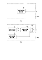
- FIG. 1 is a diagram illustrating a configuration example of the heat pump device according to the first embodiment.
- FIG. 2 is a diagram illustrating a configuration example of an inverter in the heat pump device according to the first embodiment.
- FIG. 3 is a diagram illustrating a configuration example of an inverter control unit in the heat pump apparatus according to the first embodiment.
- FIG. 4 is a diagram illustrating a configuration example of a restraint energization control unit in the heat pump device according to the first embodiment.
- FIG. 5 is a diagram for explaining the operation of the heating determination unit in the heat pump device according to the first embodiment.
- FIG. 6 is a diagram illustrating another configuration example of the refrigerant stagnation amount output unit in the heat pump device according to the first embodiment.
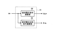
- FIG. 7 is a diagram illustrating a configuration example of a DC energization command generation unit in the heat pump device according to the first embodiment.
- FIG. 8 is a diagram illustrating a configuration example of a high-frequency energization command generation unit in the heat pump device according to the first embodiment.
- FIG. 9 is a diagram illustrating eight switching patterns in the heat pump apparatus according to the first embodiment.
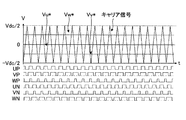
- FIG. 10 is a diagram illustrating each signal waveform when direct current energization is selected in the heat pump apparatus according to the first embodiment.
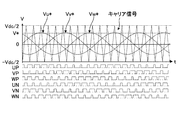
- FIG. 11 is a diagram illustrating signal waveforms when high-frequency energization is selected in the heat pump device according to the first embodiment.
- FIG. 12 is a flowchart of the refrigerant heating operation process in the heat pump device according to the first embodiment.
- FIG. 13 is a diagram illustrating a configuration example of a high-frequency energization command generation unit in the heat pump apparatus according to the second embodiment.
- FIG. 14 is a diagram illustrating signal waveforms at the time of high-frequency energization in the heat pump device according to the second embodiment.
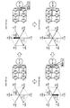
- FIG. 15 is a diagram illustrating ON / OFF states of the switching elements in the inverter corresponding to the voltage vectors.
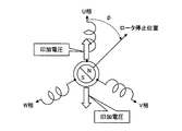
- FIG. 16 is a diagram illustrating an example of a rotor stop position of the IPM motor at the time of high-frequency energization.
- FIG. 17 is a diagram illustrating the relationship between the rotor position and each phase current.
- FIG. 18 is a diagram illustrating an applied voltage when the reference phase ⁇ f is changed.
- FIG. 19 is a diagram illustrating a current waveform of each phase when the reference phase ⁇ f is 0 °, 30 °, and 60 °.
- FIG. 20 is a diagram illustrating a configuration example of a refrigeration cycle according to the fourth embodiment.
- FIG. 21 is a Mollier diagram showing the state transition of the refrigerant in the refrigeration cycle shown in FIG.
- FIG. 1 is a diagram illustrating a configuration example of the heat pump device according to the first embodiment.
- the heat pump device 100 according to the first embodiment includes a compressor 1, a four-way valve 2, a heat exchanger 3, an expansion mechanism 4, and a heat exchanger 5 that are sequentially connected via a refrigerant pipe 6.
- a refrigeration cycle 50 is formed.
- a basic configuration for forming the refrigeration cycle 50 is shown, and some components are omitted.
- a compression mechanism 7 for compressing the refrigerant and a motor 8 for operating the compression mechanism 7 are provided inside the compressor 1.
- the motor 8 is a three-phase motor having three-phase windings of U phase, V phase, and W phase.
- An inverter 9 is electrically connected to the motor 8.
- the inverter 9 is connected to a DC voltage source 11, and uses the DC voltage (bus voltage) Vdc supplied from the DC voltage source 11 as a power source, and the voltages Vu, Vv, Vw is applied respectively.
- an inverter control unit 10 is electrically connected to the inverter 9.
- the inverter control unit 10 outputs a drive signal for driving the inverter 9 to the inverter 9.
- the inverter control unit 10 has two operation modes, a normal operation mode and a heating operation mode.
- the inverter control unit 10 In the normal operation mode, the inverter control unit 10 generates and outputs a PWM (Pulse Width Modulation) signal (drive signal) for rotationally driving the motor 8. Further, in the heating operation mode, unlike the normal operation mode, the inverter control unit 10 heats the motor 8 by energizing the motor 8 so that the motor 8 is not rotationally driven during operation standby, and stays in the compressor 1. This is an operation mode in which the liquid refrigerant is warmed and vaporized and discharged. In this heating operation mode, a direct current or a high-frequency current that cannot be followed by the motor 8 is passed through the motor 8 to heat the liquid refrigerant staying inside the compressor 1 using the heat generated in the motor 8.
- PWM Pulse Width Modulation
- heating with energization so as not to rotationally drive the motor 8 is hereinafter referred to as “restraint energization”.
- direct current energization flowing a direct current to the motor 8 to perform restraint energization
- high frequency energization flowing a high frequency current to the motor 8 to perform restraint energization
- the inverter control unit 10 includes a restraint energization control unit 12 and a drive signal generation unit 13 as components that realize the heating operation mode.
- the restraint energization control unit 12 includes a heating determination unit 14, a DC energization command generation unit 15, and a high frequency energization command generation unit 16.
- a part of the constituent elements for realizing the normal operation mode is omitted.
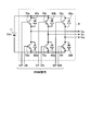
- FIG. 2 is a diagram illustrating a configuration example of the inverter 9 in the heat pump apparatus according to the first embodiment.
- the inverter 9 includes switching elements 70a to 70f that are bridge-connected, and freewheeling diodes 80a to 80f that are connected in parallel to the switching elements 70a to 70f, respectively.
- This inverter 9 is connected to a DC voltage source 11 and uses a bus voltage Vdc as a power source, and switching corresponding to each by PWM signals (UP, VP, WP, UN, VN, WN) sent from the inverter control unit 10.
- PWM signals UP, VP, WP, UN, VN, WN
- Element is driven (UP corresponds to switching element 70a, VP corresponds to switching element 70b, WP corresponds to switching element 70c, UN corresponds to switching element 70d, VN corresponds to switching element 70e, and WN corresponds to switching element 70f).
- the three-phase voltages Vu, Vv, and Vw to be applied to the V-phase and W-phase windings are generated.
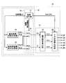
- FIG. 3 is a diagram of a configuration example of the inverter control unit according to the first embodiment.
- the inverter control unit 10 includes the restraint energization control unit 12 and the drive signal generation unit 13 that include the heating determination unit 14, the DC energization command generation unit 15, and the high-frequency energization command generation unit 16.
- the heating determination unit 14 includes a heating command unit 17 and an energization switching unit 18.
- the drive signal generation unit 13 includes a voltage command calculation unit 19 and a PWM signal generation unit 20.
- the DC energization command generation unit 15 generates a DC energization command including the DC voltage command Vdc * and the DC voltage phase command ⁇ dc based on the heating amount H * output from the heating command unit 17, and the high frequency energization command generation unit 16. Generates a high-frequency energization command including a high-frequency voltage command Vac * and a high-frequency voltage phase command ⁇ ac based on the heating amount H * output from the heating command unit 17.
- the heating command unit 17 estimates the stagnation amount of the liquid refrigerant staying in the compressor 1, outputs the necessity of heating to the drive signal generation unit 13, and obtains the heating amount H * necessary for driving out the liquid refrigerant.
- the DC energization command generation unit 15 and the high frequency energization command generation unit 16 the DC energization command including the DC voltage command Vdc * and the DC voltage phase command ⁇ dc, which are the outputs of the DC energization command generation unit 15, and the high frequency energization command generation
- the energization switching unit 18 selects either the DC voltage command Vdc * and the DC voltage phase command ⁇ dc or the high-frequency voltage command Vac * and the high-frequency voltage phase command ⁇ ac, that is, either the DC energization command or the high-frequency energization command.
- the restraint energization command including the command V * and the voltage phase command ⁇ is output to the drive signal generation unit 13.
- the voltage command calculation unit 19 generates three-phase (U-phase, V-phase, W-phase) voltage commands Vu *, Vv *, Vw * based on the voltage command V * and the voltage phase command ⁇ .
- the PWM signal generation unit 20 generates PWM signals (UP, VP, WP, UN, VN, WN) for driving the inverter 9 based on the three-phase voltage commands Vu *, Vv *, Vw * and the bus voltage Vdc. Generate.
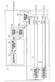
- FIG. 4 is a diagram illustrating a configuration example of a restraint energization control unit in the heat pump device according to the first embodiment.
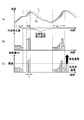
- FIG. 5 is a diagram for explaining the operation of the heating determination unit in the heat pump device according to the first embodiment.
- FIG. 5A shows the relationship between the ambient temperature around the compressor 1 (for example, the outside air temperature) Tc and the temperature of the compressor 1 (compressor temperature) To and time
- FIG. 5B shows the unit.
- the refrigerant stagnation amount per time is shown
- FIG. 5C shows the heating amount H * per unit time.
- FIG. 6 is a diagram illustrating another configuration example of the heating determination unit in the heat pump device according to the first embodiment.
- the restraint energization control unit 12 includes the heating determination unit 14, the DC energization command generation unit 15, and the high frequency energization command generation unit 16, and the heating determination unit 14 includes the heating command unit 17 and the energization switching unit 18.
- the heating command unit 17 includes a refrigerant stagnation amount output unit 40, a heating necessity determination unit 25, a heating amount calculation unit 26, and an energization switching determination unit 27.
- the refrigerant stagnation amount output unit 40 includes a temperature detection unit 21 and a refrigerant stagnation amount estimation unit 22.
- the energization switching unit 18 and the energization switching determination unit 27 constitute an energization switching control unit 33.
- the temperature detector 21 detects the ambient temperature (for example, the outside air temperature) Tc around the compressor 1 and the temperature (compressor temperature) To of the compressor 1, and the refrigerant stagnation amount estimation unit 22 Based on the compressor temperature To, the stagnation amount of the liquid refrigerant staying in the compressor 1 is estimated.
- the refrigerant circulating in the refrigeration cycle 50 condenses and accumulates at the lowest temperature among the constituent parts forming the refrigeration cycle 50. Since the compressor 1 has the largest heat capacity among the components forming the refrigeration cycle 50, the compressor temperature To rises with a delay with respect to the rise in the ambient temperature Tc, as shown in FIG. The temperature will be the lowest. For this reason, the liquid refrigerant stays inside the compressor 1.
- the refrigerant stagnation amount estimation unit 22 for example, based on the relationship between the ambient temperature Tc and the compressor temperature To obtained in advance through experiments or the like, as shown in FIG. Estimate the amount of refrigerant stagnation per t.
- the heat capacity of the compressor 1 is known in advance, only the ambient temperature Tc is detected, and by estimating how much the compressor temperature To changes with respect to the change in the ambient temperature Tc.
- the refrigerant stagnation amount per unit time t can be estimated. In this case, the number of sensors for detecting the compressor temperature To can be reduced, and the cost can be reduced.
- the temperature of the heat exchanger 3 or the like having a smaller heat capacity than that of the compressor 1 among the components forming the refrigeration cycle 50 may be similarly detected per unit time t. It goes without saying that it is possible to estimate the amount of refrigerant stagnation.
- the refrigerant stagnation amount output unit 40a is replaced with the temperature detection unit 21 and the refrigerant stagnation amount estimation unit 22 described in FIG.
- a refrigerant stagnation amount detection unit 23 for detecting the amount is provided.
- the refrigerant stagnation amount is detected more directly, it is possible to grasp the more accurate refrigerant stagnation amount.
- coolant stagnation amount inside the compressor 1 the distance between the upper part of the compressor 1 and the liquid level of a refrigerant
- coolant stagnation amount output part 40b provided with the temperature detection part 21, the refrigerant
- the heating necessity determination unit 25 determines whether or not the compressor 1 needs to be heated based on the refrigerant stagnation amount that is the output of the refrigerant stagnation amount output unit 40 (or 40a or 40b). If the compressor 1 needs to be heated, that is, if the liquid refrigerant stays inside the compressor 1 or if it is estimated that the liquid refrigerant stays inside the compressor 1, heating is performed.
- the necessity determination unit 25 outputs an ON signal to the PWM signal generation unit 20 and instructs the heating amount calculation unit 26 to start calculation of the heating amount H * necessary for expelling the liquid refrigerant staying inside the compressor 1.
- the heating necessity determination unit 25 outputs an OFF signal to the PWM signal generation unit 20.
- the heating amount calculation unit 26 When the heating amount calculation unit 26 is instructed by the heating necessity determination unit 25 to start calculating the heating amount H *, the heating amount calculation unit 26 sets the refrigerant stagnation amount, which is the output of the refrigerant stagnation amount output unit 40 (or 40a or 40b). Accordingly, the heating amount H * necessary to drive out the liquid refrigerant staying in the compressor 1 is calculated and output to the DC energization command generation unit 15, the high frequency energization command generation unit 16, and the energization switching determination unit 27.
- This heating amount H * varies depending on the type and size of the compressor 1, and when the compressor 1 is large or the material or shape is difficult to transmit heat, the heating amount H * may be set high.
- the energization switching determination unit 27 has a threshold value for determining whether to perform direct current energization or high frequency energization in advance, and the heating amount H * is greater than or less than the threshold.
- the energization switching unit 18 is controlled based on whether or not When the heating amount H * is equal to or greater than the threshold value, the energization switching determination unit 27 selects the DC voltage command Vdc * and the DC voltage phase command ⁇ dc output from the DC energization command generation unit 15 by the energization switching unit 18 (hereinafter referred to as “the heating amount H *”).
- the high-frequency voltage command Vac * and the high-frequency voltage phase command ⁇ ac output from the high-frequency energization command generation unit 16 by the switching unit 18 are selected (hereinafter referred to as “select high-frequency energization”) to be used as the voltage command V * and the voltage phase command ⁇ . Control to output.
- FIG. 7 is a diagram illustrating a configuration example of a DC energization command generation unit in the heat pump device according to the first embodiment.
- the DC energization command generation unit 15 includes a DC voltage command calculation unit 28 and a DC voltage phase command calculation unit 29.
- the DC voltage command calculator 28 stores in advance the relationship between the heating amount H * and the DC voltage command Vdc * as table data, and the DC voltage command calculator 28 determines the DC voltage according to the heating amount H * input from the heating amount calculator 26.
- Command Vdc * is calculated and output.
- the heating amount H * is input.
- various information such as the ambient temperature (for example, the outside air temperature) Tc and the compressor temperature To around the compressor 1 and information on the structure of the compressor 1 can be used. It goes without saying that the reliability of the DC voltage command Vdc * can be improved by using the data.
- the DC voltage phase command calculation unit 29 obtains a DC voltage phase command ⁇ dc for energizing the motor 8.
- FIG. 8 is a diagram illustrating a configuration example of a high-frequency energization command generation unit in the heat pump device according to the first embodiment.
- the high frequency energization command generation unit 16 includes a high frequency voltage command calculation unit 30 and a high frequency voltage phase command calculation unit 31.
- the high-frequency voltage command calculation unit 30 stores in advance the relationship between the heating amount H * and the high-frequency voltage command Vac * as table data, and according to the heating amount H * input from the heating amount calculation unit 26, the high-frequency voltage command calculation unit 30 Command Vac * is calculated and output.
- the heating amount H * is input, but the ambient temperature (for example, the outside air temperature) Tc, the compressor temperature To, and the compressor around the compressor 1 are the same as the DC voltage command calculation unit 28. It goes without saying that the reliability of the high-frequency voltage command Vac can be improved by using various data such as information relating to the structure of 1.
- the high-frequency voltage phase command calculation unit 31 obtains a high-frequency voltage phase command ⁇ ac for energizing the motor 8.
- the high frequency voltage phase command ⁇ ac is continuously changed in the range of 0 ° to 360 °.
- the frequency of the high frequency voltage can be increased by shortening the period in which the high frequency voltage phase command ⁇ ac changes in the range of 0 ° to 360 °.
- the iron loss can be increased to increase the amount of heat generation, and furthermore, the impedance due to the inductance of the motor 8 can be increased. It is possible to suppress the loss of the inverter 9 and highly efficient heating of the liquid refrigerant staying inside the motor 8 is possible, which is suitable for heating the refrigerant for a long time during operation standby. For this reason, it is possible to save energy by reducing standby power and contribute to the prevention of global warming.
- the liquid refrigerant when the heating amount H * is large, the liquid refrigerant is discharged in a short time by increasing the heating amount by performing direct current energization, and when the heating amount H * is small.
- the power consumption is reduced by conducting high-frequency energization.
- each voltage command value Vu *, Vv *, Vw * is defined as a cosine wave (sine wave) whose phase is different by 2 ⁇ / 3 as shown in the following equations (1) to (3).
- Vu * V * ⁇ cos ⁇ (1)
- Vv * V * ⁇ cos ( ⁇ (2/3) ⁇ ) (2)
- Vw * V * ⁇ cos ( ⁇ + (2/3) ⁇ ) (3)
- the voltage command calculation unit 19 calculates each voltage command value Vu *, Vv *, Vw * using the above equations (1) to (3) to generate a PWM signal.
- the PWM signal generation unit 20 compares each voltage command value Vu *, Vv *, Vw * with a carrier signal (reference signal) having an amplitude value of ⁇ (Vdc / 2) at a predetermined frequency, and the magnitude relationship between them.
- the PWM signals UP, VP, WP, UN, VN, and WN are generated based on the above.
- each voltage command Vu *, Vv *, Vw * is obtained by a simple trigonometric function.
- two-phase modulation or third harmonic superposition modulation is used.
- the voltage commands Vu *, Vv *, and Vw * may be obtained using other methods such as space vector modulation.
- UP is a voltage for turning on the switching element 70a
- UN is a voltage for turning off the switching element 70d.
- VP and VN are determined by comparing the voltage command value Vv * and the carrier signal
- WP and WN are determined by comparing the voltage command value Vw * and the carrier signal.
- FIG. 9 is a diagram illustrating eight switching patterns in the heat pump apparatus according to the first embodiment.
- the voltage vectors generated in each switching pattern are denoted by symbols V0 to V7.
- the voltage direction of each voltage vector is represented by ⁇ U, ⁇ V, ⁇ W (0 when no voltage is generated).
- + U is a voltage that generates a current in the U-phase direction that flows into the motor 8 via the U-phase and flows out of the motor 8 via the V-phase and the W-phase
- ⁇ U is the V-phase.
- a voltage that generates a current in the ⁇ U-phase direction that flows into the motor 8 via the W-phase and flows out of the motor 8 via the U-phase The same interpretation is applied to ⁇ V and ⁇ W.
- a desired voltage can be output to the inverter 9 by combining the switching patterns shown in FIG.
- the operation is generally performed in a range of several tens Hz to several kHz.
- direct current energization in the heating operation mode can be performed by setting the voltage phase command ⁇ to a fixed value
- high frequency energization in the heating operation mode can be performed by changing the voltage phase command ⁇ at a higher speed than in the normal operation mode. It can be performed.
- FIG. 10 is a diagram illustrating signal waveforms when direct current energization is selected in the heat pump apparatus according to the first embodiment.
- FIG. PWM signals UP, VP, WP, UN, VN, WN are obtained, and the voltage vectors V0 (0 voltage), V2 (+ V voltage), V6 (-W voltage), and V7 (0 voltage) in FIG. 9 are output.
- a direct current can be passed through the motor 8.
- FIG. 11 is a diagram illustrating signal waveforms when high-frequency energization is selected in the heat pump apparatus according to the first embodiment.
- the voltage phase command ⁇ is set to 0 ° to 360 °. Therefore, as shown in FIG. 11, Vu *, Vv *, and Vw * are sine (cosine) waves with a phase difference of 120 °.
- the PWM signals UP, VP, WP, UN, VN, WN shown in FIG. 11 are obtained, the voltage vector changes with time, and a high-frequency current can flow through the motor 8. Become.
- FIG. 12 is a flowchart of the refrigerant heating operation process in the heat pump device according to the first embodiment. As shown in FIG. 12, the refrigerant heating operation process in the heat pump device according to the first embodiment is divided into four steps: a heating determination step, an energization switching step, a voltage command value calculation step, and a PWM signal generation step.
- the heating necessity determination unit 25 determines whether or not the compressor 1 needs to be heated (step ST101). In the present embodiment, as described above, the heating necessity determination unit 25 determines whether or not the compressor 1 needs to be heated based on the refrigerant stagnation amount that is the output of the refrigerant stagnation amount output unit 40.
- the heating necessity determination unit 25 When heating to the compressor 1 is unnecessary, that is, when it is estimated that the liquid refrigerant does not stay in the compressor 1 or that the liquid refrigerant does not stay inside the compressor 1 (step) ST101; No), the heating necessity determination unit 25 outputs an OFF signal to the PWM signal generation unit 20 and repeats this heating necessity determination step until the compressor 1 needs to be heated.
- the heating necessity determination unit 25 When heating to the compressor 1 is necessary, that is, when it is estimated that the liquid refrigerant stays inside the compressor 1 or when the liquid refrigerant stays inside the compressor 1 (step) ST101; Yes), the heating necessity determination unit 25 outputs an ON signal to the PWM signal generation unit 20, and at the same time, the heating amount H required to expel the liquid refrigerant staying in the compressor 1 to the heating amount calculation unit 26. Instructs to start * calculation.
- the heating amount calculation unit 26 calculates the heating amount H * according to the refrigerant stagnation amount, It outputs to the high frequency energization command generation part 16 and the energization switching judgment part 27 (step ST102).
- the DC energization command generator 15 generates a DC voltage command Vdc * and a DC voltage phase command ⁇ dc in accordance with the heating amount H *, and the high-frequency energization command generator 16 in response to the heating amount H *.
- a high frequency voltage command Vac * and a high frequency voltage phase command ⁇ ac are generated (step ST103).
- the energization switching determination unit 27 determines whether the heating amount H * is greater than or less than the threshold (step ST104).
- the energization switching determination unit 27 selects DC energization when the heating amount H * is equal to or greater than the threshold (step ST104; Yes), and the DC voltage command Vdc * and the DC voltage phase output from the DC energization command generation unit 15 are selected.
- the energization switching unit 18 is controlled so that the command ⁇ dc is output.
- high-frequency energization is selected (step ST104; No), and is output from the high-frequency energization command generation unit 16.
- the energization switching unit 18 is controlled so that the high-frequency voltage command Vac * and the high-frequency voltage phase command ⁇ ac are output.
- step ST104 When DC energization is selected (step ST104; Yes), the voltage command calculation unit 19 determines each voltage command value Vu *, Vv based on the DC voltage command Vdc * and the DC voltage phase command ⁇ dc that are DC energization commands. * And Vw * are calculated and output to the PWM signal generator 20 (step ST105a).
- step ST104 when high-frequency energization is selected (step ST104; No), the voltage command calculation unit 19 determines each voltage command value Vu * based on the high-frequency voltage command Vac * and the high-frequency voltage phase command ⁇ ac that are high-frequency energization commands. , Vv *, Vw * are calculated and output to the PWM signal generator 20 (step ST105b).
- the PWM signal generator 20 generates each PWM signal UP, VP, WP, UN, VN, WN based on each voltage command value Vu *, Vv *, Vw *, and supplies it to each switching element 70a to 70f of the inverter 9. Output (step ST106), return to step ST101, and repeat the processing of step ST101 to step ST106 until the operation in the normal operation mode is started.
- the heat pump device of the first embodiment during the standby state of the compressor, when the liquid refrigerant stays inside the compressor, or when the liquid refrigerant stays inside the compressor.
- the amount of heat required to vaporize and discharge the liquid refrigerant that has accumulated inside the compressor is determined based on the detected or estimated amount of refrigerant stagnation. If it is equal to or higher than the threshold value, restraint energization by DC voltage application, that is, DC energization is performed. If it is less than the threshold value, restraint energization by high frequency voltage application, that is, high frequency energization is performed.
- the frequency of the voltage output from the inverter be equal to or higher than the operation frequency during the compression operation.
- a high-frequency voltage of 1 kHz or more that is the operating frequency at the time of the compression operation is applied to the motor when high-frequency energization is performed while the compressor is on standby. do it.
- a high frequency voltage of 14 kHz or higher is applied to the motor, the vibration sound of the motor iron core approaches the audible frequency upper limit, which is effective in reducing noise.
- a high-frequency voltage of about 20 kHz outside the audible frequency is set, noise can be further reduced.
- switching in the inverter is performed to ensure reliability. It is desirable to apply a high-frequency voltage below the maximum rated frequency of the element.
- the motor of the compressor is an IPM (Interior Permanent Magnet) structure embedded magnet type motor
- IPM Interior Permanent Magnet
- the surface of the rotor where the high-frequency magnetic flux interlinks becomes a heat generating portion when high-frequency current is applied Therefore, rapid heating of the compression mechanism can be realized by increasing the refrigerant contact surface, and more efficient refrigerant heating can be achieved.
- the example in which the direct current energization and the high frequency energization are switched according to the heating amount necessary for vaporizing and discharging the liquid refrigerant staying inside the compressor has been described. It is also possible to configure the inverter control unit so that a direct current and a high-frequency current flow simultaneously. In that case, a large amount of heat generation, which is a merit of direct current conduction described above, and a low loss, which is a merit of high-frequency conduction. Combined restraint energization is possible.
- Embodiment 2 the example in which the voltage phase command ⁇ is continuously changed in the range of 0 ° to 360 ° in high-frequency energization has been described, but in the present embodiment, the voltage phase is inverted in synchronization with the carrier frequency. Thus, an example in which high-frequency energization equal to the carrier frequency is performed will be described.
- FIG. 13 is a diagram illustrating a configuration example of a high-frequency energization command generation unit in the heat pump apparatus according to the second embodiment.
- FIG. 14 is a figure which shows each signal waveform at the time of the high frequency electricity supply in the heat pump apparatus concerning Embodiment 2.
- FIG. 14 since the whole structure of the heat pump apparatus concerning Embodiment 2 is the same as the whole structure of the heat pump apparatus concerning Embodiment 1, description is abbreviate
- the high-frequency energization command generation unit 16a in the second embodiment is a high frequency that inverts the output of the high-frequency voltage phase command calculation unit 31 in synchronization with the carrier signal.
- a phase switching unit 32 is provided.
- the upper limit of the carrier frequency which is the frequency of the carrier signal, is determined by the switching speed of the switching element of the inverter. For this reason, it is difficult to output a high-frequency voltage equal to or higher than the carrier frequency that is a carrier wave.
- the upper limit of the switching speed is about 20 kHz.
- the frequency of the high frequency voltage is about 1/10 or more of the carrier frequency
- the waveform output accuracy of the high frequency voltage is deteriorated and there is a possibility of adverse effects such as superposition of DC components.
- the frequency of the high frequency voltage is 1/10 or less of the carrier frequency, for example, when the carrier frequency is 20 kHz, the frequency of the high frequency voltage is 2 kHz or less and falls within the audible frequency band. Noise caused by electromagnetic noise of the motor becomes a problem.
- the voltage phase (hereinafter referred to as “reference phase”) output from the high-frequency voltage phase command calculation unit 31 is a fixed value, and as shown in FIG.
- the output from the high-frequency voltage phase command calculation unit 31 is inverted by 180 ° in the period up to the top, that is, in one cycle (1 / fc) of the carrier frequency fc.
- Synchronized high-accuracy PWM signals UP, VP, WP, UN, VN, and WN are generated.
- FIG. 15 is a diagram showing the ON / OFF state of each switching element in the inverter corresponding to each voltage vector.
- the switching element surrounded by a broken line is ON, and the others are OFF.
- the rotation direction of thick arrows indicating the change order of voltage vectors corresponds to the example shown in FIG.
- each PWM signal UP, VP, WP, UN, VN, WN makes one rotation of the four circuit states in FIG. 15 in one carrier cycle.
- a current having one carrier period as one period is supplied to the motor 8.
- V4 vector and the V3 vector are alternately output, and + Iu and -Iu flow alternately in the winding of the motor 8, so that the forward and reverse torques are instantaneously switched. For this reason, forward and reverse torques are canceled out, and it is possible to apply a voltage that suppresses vibration of the rotor.
- the reference phase output from the high-frequency voltage phase command calculation unit is a fixed value, and is inverted in synchronization with the frequency of the carrier signal, so that it is equal to the carrier frequency. Since high-frequency energization is performed, a high-accuracy high-frequency voltage synchronized with the frequency of the carrier signal can be applied to the winding of the motor, and noise due to electromagnetic noise of the motor can be suppressed.
- the V4 vector and the V3 vector are alternately output via the V0 vector and the V7 vector, and the direction of the U-phase current is instantaneously switched. Since the forward and reverse torques are instantaneously switched and the forward and reverse torques are canceled out, the vibration of the rotor can be suppressed.
- Embodiment 3 FIG.
- the example in which the voltage phase (reference phase) output from the high-frequency voltage phase command calculation unit is a fixed value has been described.
- the present embodiment an example in which the reference phase is changed over time is described. To do.
- the whole structure of the heat pump apparatus concerning Embodiment 3 the structure of an inverter control part, and the structure of a restraint electricity supply control part are the same as the whole structure of the heat pump apparatus concerning Embodiment 1, it demonstrates here. Omitted.
- the configuration of the high-frequency energization command generation unit in the heat pump device according to the third embodiment is the same as the configuration of the high-frequency energization command generation unit in the heat pump device according to the second embodiment, and thus description thereof is omitted here.
- FIG. 16 is a diagram illustrating an example of the rotor stop position of the IPM motor when high-frequency current is applied.
- the motor 8 is an IPM motor (Interior Permanent Magnet Motor)
- the rotor stop position of the motor 8 is an angle at which the direction of the N pole of the rotor is deviated from the U-phase direction. It is represented by the size of ⁇ .
- FIG. 17 is a diagram showing the relationship between the rotor position and each phase current.
- the winding inductance value at the time of high-frequency energization depends on the rotor position. Therefore, the winding impedance represented by the product of the electrical angular frequency ⁇ and the winding inductance value varies depending on the rotor position. Therefore, even when the same voltage is applied during DC energization during operation standby, the current flowing through the winding of the motor 8 varies depending on the rotor stop position, and the amount of heating changes. As a result, depending on the rotor stop position, a large amount of electric power may be consumed in order to obtain a necessary heating amount.
- FIG. 18 is a diagram showing an applied voltage when the reference phase ⁇ f is changed.
- the high-frequency voltage phase command ⁇ ac which is the output of the high-frequency energization command generation unit 16a, is switched between 0 ° and 180 °.
- ⁇ ac is switched between 45 ° and 225 °.
- ⁇ ac is switched between 90 ° and 270 °.
- the high-frequency voltage phase command ⁇ ac that is inverted in synchronization with the carrier signal also changes by 45 °. Regardless of the stop position, the voltage can be uniformly applied to the rotor, and the liquid refrigerant staying in the compressor 1 can be efficiently heated.
- FIG. 19 is a diagram showing each phase current waveform when the reference phase ⁇ f is 0 °, 30 °, and 60 °.
- each phase current waveform has a trapezoidal shape and becomes a current with less harmonic components.
- each phase current waveform has a trapezoidal shape and is a current with less harmonic components.
- each phase current waveform is distorted and harmonics as shown in FIG.
- the current has a lot of wave components.
- the distortion of each phase current waveform may cause factors such as motor noise and motor shaft vibration.
- each phase current waveform has a trapezoidal shape and a current with less harmonic components.
- the reference phase ⁇ f when the reference phase ⁇ f is switched other than n times of 60 °, the high-frequency voltage phase command ⁇ ac does not become a multiple of 60 °, so that another voltage vector is 2 between the V0 vector and the V7 vector. Each phase current waveform is distorted, resulting in a current with many harmonic components. Therefore, it is desirable to change the reference phase ⁇ f in multiples of 60 °, such as 0 °, 60 °, 120 °,.
- the energization phase of the high-frequency AC voltage is changed when the high-frequency energization is performed by changing the reference phase output from the high-frequency voltage phase command calculation unit every predetermined time. Is changed every predetermined time, so that the influence of the inductance characteristics due to the rotor stop position can be eliminated, and the liquid refrigerant staying inside the compressor can be heated efficiently and uniformly regardless of the rotor stop position. Can do.
- the reference phase is changed at a multiple of 60 ° every predetermined time, harmonic components of each phase current waveform can be suppressed, and motor noise and motor shaft vibration can be prevented.
- Embodiment 4 FIG. In this embodiment, an air conditioner, a heat pump water heater, a refrigerator, and a refrigerator to which the heat pump device described in Embodiments 1 to 3 can be applied will be described.
- FIG. 20 is a diagram illustrating a configuration example of a refrigeration cycle according to the fourth embodiment.
- FIG. 21 is a Mollier diagram showing refrigerant state transition in the refrigeration cycle shown in FIG.
- the horizontal axis represents specific enthalpy and the vertical axis represents refrigerant pressure.
- the refrigeration cycle 50a includes a compressor 51, a heat exchanger 52, an expansion mechanism 53, a receiver 54, an internal heat exchanger 55, an expansion mechanism 56, and a heat exchanger 57. Are connected to each other in order to form a main refrigerant circuit 58 through which the refrigerant circulates.
- a four-way valve 59 is provided on the discharge side of the compressor 51 so that the refrigerant circulation direction can be switched.
- a fan 60 is provided in the vicinity of the heat exchanger 57.
- a compressor 51 that compresses the refrigerant and a motor 8 that operates the compressor 7 are provided inside the compressor 51.
- the refrigeration cycle 50a includes an injection circuit 62 that connects between the receiver 54 and the internal heat exchanger 55 to the injection pipe of the compressor 51 by piping.
- An expansion mechanism 61 and an internal heat exchanger 55 are sequentially connected to the injection circuit 62.
- a water circuit 63 through which water circulates is connected to the heat exchanger 52.
- the water circuit 63 is connected to a device that uses water such as a water heater (not shown), a radiator (not shown), a radiator (not shown) such as floor heating.
- the heating operation includes not only a heating operation in an air conditioner but also a hot water supply operation in which heat is applied to water to produce hot water in a heat pump water heater.
- the gas-phase refrigerant (point A in FIG. 21) that has become high temperature and high pressure in the compressor 51 is discharged from the compressor 51, and is liquefied by heat exchange in a heat exchanger 52 that is a condenser and a radiator. (Point B in FIG. 21).
- the water circulated through the water circuit 63 is warmed by the heat radiated from the refrigerant, and is used for the heating operation in the air conditioner and the hot water supply operation in the heat pump water heater.
- the liquid-phase refrigerant liquefied by the heat exchanger 52 is decompressed by the expansion mechanism 53 and becomes a gas-liquid two-phase state (point C in FIG. 21).
- the refrigerant in the gas-liquid two-phase state by the expansion mechanism 53 is heat-exchanged with the refrigerant sucked into the compressor 51 by the receiver 54, cooled, and liquefied (point D in FIG. 21).
- the liquid phase refrigerant liquefied by the receiver 54 branches and flows into the main refrigerant circuit 58 and the injection circuit 62.
- the liquid phase refrigerant flowing through the main refrigerant circuit 58 is heat-exchanged by the internal heat exchanger 55 with the refrigerant flowing through the injection circuit 62 that has been decompressed by the expansion mechanism 61 and is in a gas-liquid two-phase state, and further cooled (FIG. 21). E point).
- the liquid-phase refrigerant cooled by the internal heat exchanger 55 is decompressed by the expansion mechanism 56 and becomes a gas-liquid two-phase state (point F in FIG. 21).
- the refrigerant that has been in the gas-liquid two-phase state by the expansion mechanism 56 is heat-exchanged with the outside air by the heat exchanger 57 serving as an evaporator and heated (point G in FIG. 21). Then, the refrigerant heated by the heat exchanger 57 is further heated by the receiver 54 (point H in FIG. 21) and sucked into the compressor 51.
- the refrigerant flowing through the injection circuit 62 is decompressed by the expansion mechanism 61 (point I in FIG. 21), and is heat-exchanged by the internal heat exchanger 55 (point J in FIG. 21).
- the gas-liquid two-phase refrigerant (injection refrigerant) heat-exchanged by the internal heat exchanger 55 flows into the compressor 51 from the injection pipe of the compressor 51 in the gas-liquid two-phase state.
- the refrigerant (point H in FIG. 21) sucked from the main refrigerant circuit 58 is compressed and heated to an intermediate pressure (point K in FIG. 21).
- the injection refrigerant (point J in FIG. 21) joins the refrigerant compressed to the intermediate pressure and heated (point K in FIG. 21), and the temperature decreases (point L in FIG. 21).
- the refrigerant whose temperature has decreased (point L in FIG. 21) is further compressed and heated to become high temperature and pressure and discharged (point A in FIG. 21).
- the opening of the expansion mechanism 61 is fully closed. That is, when the injection operation is performed, the opening degree of the expansion mechanism 61 is larger than the predetermined opening degree. However, when the injection operation is not performed, the opening degree of the expansion mechanism 61 is more than the predetermined opening degree. Make it smaller. Thereby, the refrigerant does not flow into the injection pipe of the compressor 51.
- the opening degree of the expansion mechanism 61 is controlled by electronic control by a control unit (not shown) such as a microcomputer.
- the cooling operation includes not only the cooling operation in the air conditioner but also the production of cold water by taking heat from water in the refrigerator and the freezing operation in the refrigerator.
- the gas-phase refrigerant (point A in FIG. 21) that has become high-temperature and high-pressure in the compressor 51 is discharged from the compressor 51, and is heat-exchanged and liquefied by a heat exchanger 57 that is a condenser and a radiator. B point).
- the liquid-phase refrigerant liquefied by the heat exchanger 57 is decompressed by the expansion mechanism 56 and becomes a gas-liquid two-phase state (point C in FIG. 21).
- the refrigerant in the gas-liquid two-phase state by the expansion mechanism 56 is heat-exchanged by the internal heat exchanger 55, cooled and liquefied (point D in FIG. 21).
- the refrigerant that has become a gas-liquid two-phase state by the expansion mechanism 56 and the liquid-phase refrigerant that has been liquefied by the internal heat exchanger 55 have been decompressed by the expansion mechanism 61, and have become a gas-liquid two-phase state.
- Heat exchange is performed with the refrigerant (point I in FIG. 21).
- the liquid-phase refrigerant (point D in FIG. 21) heat-exchanged by the internal heat exchanger 55 branches and flows to the main refrigerant circuit 58 and the injection circuit 62.
- the liquid-phase refrigerant flowing through the main refrigerant circuit 58 is heat-exchanged with the refrigerant sucked into the compressor 51 by the receiver 54 and further cooled (point E in FIG. 21).
- the liquid-phase refrigerant cooled by the receiver 54 is decompressed by the expansion mechanism 53 and becomes a gas-liquid two-phase state (point F in FIG. 21).
- the refrigerant in the gas-liquid two-phase state by the expansion mechanism 53 is heat-exchanged and heated by the heat exchanger 52 serving as an evaporator (point G in FIG. 21).
- the water circulating in the water circuit 63 is cooled and used for the cooling operation in the air conditioner and the refrigeration operation in the refrigerator.
- the refrigerant heated by the heat exchanger 52 is further heated by the receiver 54 (H point in FIG. 21) and sucked into the compressor 51.
- the refrigerant flowing through the injection circuit 62 is decompressed by the expansion mechanism 61 (point I in FIG. 21), and is heat-exchanged by the internal heat exchanger 55 (point J in FIG. 21).
- the gas-liquid two-phase refrigerant (injection refrigerant) heat-exchanged by the internal heat exchanger 55 flows into the compressor 51 from the injection pipe of the compressor 51 in the gas-liquid two-phase state.
- the opening of the expansion mechanism 61 is fully closed so that the refrigerant does not flow into the injection pipe of the compressor 51, as in the heating operation.
- the heat exchanger 52 has been described as a heat exchanger such as a plate heat exchanger that exchanges heat between the refrigerant and the water circulating in the water circuit 63.
- the heat exchanger 52 is not limited to this and may exchange heat between the refrigerant and the air.
- the water circuit 63 may be a circuit in which other fluid circulates instead of a circuit in which water circulates.
- the embodiment As described above, according to the air conditioner, the heat pump water heater, the refrigerator, and the refrigerator of the fourth embodiment, by applying the heat pump device described in the first to third embodiments, the embodiment The effects described in 1 to 3 can be obtained, energy can be saved by reducing standby power, and contribution to global warming prevention.
- the switching element constituting the inverter in the above-described embodiment and the freewheeling diode connected in parallel to the switching element, it is generally mainstream to use a Si-based semiconductor made of silicon (Si: silicon).
- a wide band gap (WBG) semiconductor made of silicon carbide (SiC), gallium nitride (GaN), or diamond may be used.
- a switching element or a diode element formed of such a WBG semiconductor has a high withstand voltage and a high allowable current density. Therefore, the switching element and the diode element can be reduced in size, and by using these reduced switching element and diode element, the semiconductor module incorporating these elements can be reduced in size.
- the switching element and the diode element formed of such a WBG semiconductor have high heat resistance.
- the heat sink fins of the heat sink can be miniaturized and the water cooling part can be air cooled, so that the semiconductor module can be further miniaturized.
- switching elements and diode elements formed of such WBG semiconductors have low power loss. For this reason, it is possible to increase the efficiency of the switching element and the diode element, and to increase the efficiency of the semiconductor module.
- both the switching element and the diode element are preferably formed of a WBG semiconductor, any one of the elements may be formed of a WBG semiconductor, and the effects in the above-described embodiments can be obtained. .
- the same effect can be obtained by using a super junction structure MOSFET (Metal-Oxide-Semiconductor Field-Effect Transistor) known as a highly efficient switching element in addition to the WBG semiconductor.
- MOSFET Metal-Oxide-Semiconductor Field-Effect Transistor
- the compressor with the scroll mechanism it is difficult for the compressor with the scroll mechanism to perform high-pressure relief of the compression chamber. Therefore, compared with other types of compressors, there is a high possibility that excessive compression will be applied to the compression mechanism when liquid compression is performed.
- the compressor in the heat pump device according to the above-described embodiment, the compressor can be efficiently heated, and the retention of the liquid refrigerant in the compressor can be suppressed. Therefore, since liquid compression can be prevented, it is effective also when using the compressor of a scroll mechanism.
- the voltage command V * may be adjusted in advance so as not to exceed 50 W, or the feedback control may be performed so that the flowing current and voltage are detected and become 50 W or less.
- the inverter control unit can be constituted by a discrete system of CPU (Central Processing Unit), DSP (Digital Signal Processor), and microcomputer (microcomputer), and other electric circuit elements such as analog circuits and digital circuits. It may be configured.
- CPU Central Processing Unit
- DSP Digital Signal Processor
- microcomputer microcomputer
Abstract
Description
図1は、実施の形態1にかかるヒートポンプ装置の一構成例を示す図である。図1に示すように、実施の形態1にかかるヒートポンプ装置100は、圧縮機1、四方弁2、熱交換器3、膨張機構4、および熱交換器5が冷媒配管6を介して順次接続され、冷凍サイクル50が形成される。なお、図1に示す例では、冷凍サイクル50を形成する基本的な構成を示しており、一部構成要素を省略した図としている。
FIG. 1 is a diagram illustrating a configuration example of the heat pump device according to the first embodiment. As shown in FIG. 1, the
Vv*=V*×cos(θ-(2/3)π) … (2)
Vw*=V*×cos(θ+(2/3)π) … (3) Vu * = V * × cos θ (1)
Vv * = V * × cos (θ− (2/3) π) (2)
Vw * = V * × cos (θ + (2/3) π) (3)
実施の形態1では、高周波通電において電圧位相指令θを0°~360°の範囲で連続的に変化させる例について説明したが、本実施の形態では、キャリア周波数に同期して電圧位相を反転させることにより、キャリア周波数に等しい高周波通電を実施する例について説明する。
In the first embodiment, the example in which the voltage phase command θ is continuously changed in the range of 0 ° to 360 ° in high-frequency energization has been described, but in the present embodiment, the voltage phase is inverted in synchronization with the carrier frequency. Thus, an example in which high-frequency energization equal to the carrier frequency is performed will be described.
実施の形態2では、高周波電圧位相指令演算部から出力させる電圧位相(基準位相)を固定値とする例について説明したが、本実施の形態では、基準位相を時間の経過と共に変化させる例について説明する。なお、実施の形態3にかかるヒートポンプ装置の全体構成、インバータ制御部の構成、および拘束通電制御部の構成は、実施の形態1にかかるヒートポンプ装置の全体構成と同一であるので、ここでは説明を省略する。また、実施の形態3にかかるヒートポンプ装置における高周波通電指令生成部の構成は、実施の形態2にかかるヒートポンプ装置における高周波通電指令生成部の構成と同一であるので、ここでは説明を省略する。
In the second embodiment, the example in which the voltage phase (reference phase) output from the high-frequency voltage phase command calculation unit is a fixed value has been described. However, in the present embodiment, an example in which the reference phase is changed over time is described. To do. In addition, since the whole structure of the heat pump
本実施の形態では、実施の形態1~3に記載したヒートポンプ装置を適用可能な空気調和機、ヒートポンプ給湯機、冷蔵庫、および冷凍機について説明する。
In this embodiment, an air conditioner, a heat pump water heater, a refrigerator, and a refrigerator to which the heat pump device described in
2 四方弁
3 熱交換器
4 膨張機構
5 熱交換器
6 冷媒配管
7 圧縮機構
8 モータ
9 インバータ
10 インバータ制御部
11 直流電圧源
12 拘束通電制御部
13 駆動信号生成部
14 加熱判定部
15 直流通電指令生成部
16,16a 高周波通電指令生成部
17 加熱指令部
18 通電切替部
19 電圧指令算出部
20 PWM信号生成部
21 温度検出部
22 冷媒寝込量推定部
23 冷媒寝込量検出部
24 冷媒寝込判定切替部
25 加熱要否判定部
26 加熱量演算部
27 通電切替判断部
28 直流電圧指令演算部
29 直流電圧位相指令演算部
30 高周波電圧指令演算部
31 高周波電圧位相指令演算部
32 高周波位相切替部
33 通電切替制御部
40,40a,40b 冷媒寝込量出力部
50,50a 冷凍サイクル
51 圧縮機
52,57 熱交換器
53,56,61 膨張機構
54 レシーバ
55 内部熱交換器
58 主冷媒回路
59 四方弁
60 ファン
62 インジェクション回路
63 水回路
70a~70f スイッチング素子
80a~80f 還流ダイオード
100 ヒートポンプ装置 DESCRIPTION OF
Claims (16)
- 冷媒を圧縮する圧縮機構と前記圧縮機構を駆動するモータとを有する圧縮機と、熱交換器と、前記モータに所望の電圧を印加するインバータと、前記インバータを駆動する駆動信号を生成するインバータ制御部と、を備えるヒートポンプ装置であって、
前記インバータ制御部は、
前記圧縮機の運転待機中において、前記圧縮機への冷媒寝込量に基づいて、当該圧縮機への加熱が必要であるか否かを判定すると共に、当該圧縮機への加熱が必要であると判定した場合に、前記冷媒寝込量に応じて、前記モータに直流電圧を供給する直流通電と前記モータに通常運転時よりも高い周波数の高周波電圧を供給する高周波通電とのうち、いずれか一方を選択して、前記モータの拘束通電を実施するための拘束通電指令を出力する拘束通電制御部と、
前記拘束通電指令に基づき前記駆動信号を生成する駆動信号生成部と、
を備えることを特徴とするヒートポンプ装置。 A compressor having a compression mechanism for compressing refrigerant and a motor for driving the compression mechanism, a heat exchanger, an inverter for applying a desired voltage to the motor, and an inverter control for generating a drive signal for driving the inverter A heat pump device comprising:
The inverter control unit
While waiting for operation of the compressor, it is determined whether or not the compressor needs to be heated based on the refrigerant stagnation amount in the compressor, and the compressor needs to be heated. If it is determined that, depending on the refrigerant stagnation amount, either DC energization for supplying a DC voltage to the motor or high-frequency energization for supplying a high-frequency voltage of a higher frequency to the motor than during normal operation. A constraint energization control unit that selects one and outputs a constraint energization command for performing the energization of the motor;
A drive signal generator that generates the drive signal based on the restraint energization command;
A heat pump device comprising: - 前記拘束通電制御部は、
前記冷媒寝込量を推定あるいは検出して出力する冷媒寝込量出力部と
前記冷媒寝込量に応じた加熱量を演算する加熱量演算部と、
前記加熱量に基づいて、前記直流通電を実施するための直流電圧指令および直流電圧位相指令を含む直流通電指令を生成する直流通電指令生成部と、
前記加熱量に基づいて、前記高周波通電を実施するための高周波電圧指令および高周波電圧位相指令を含む高周波通電指令を生成する高周波通電指令生成部と、
前記加熱量に基づいて、前記直流通電指令と前記高周波通電指令とを切り替え、前記拘束通電指令として出力する通電切替判断部と、
を備えることを特徴とする請求項1に記載のヒートポンプ装置。 The restraint energization control unit
A refrigerant stagnation amount output unit that estimates or detects the refrigerant stagnation amount and outputs; and a heating amount calculation unit that calculates a heating amount according to the refrigerant stagnation amount;
A DC energization command generating unit that generates a DC energization command including a DC voltage command and a DC voltage phase command for performing the DC energization based on the heating amount;
A high-frequency energization command generating unit that generates a high-frequency energization command including a high-frequency voltage command and a high-frequency voltage phase command for performing the high-frequency energization based on the heating amount;
An energization switching determination unit that switches between the DC energization command and the high-frequency energization command based on the heating amount and outputs the restraint energization command,
The heat pump device according to claim 1, comprising: - 前記通電切替判断部は、あらかじめ定められた閾値と前記加熱量とを比較して、前記加熱量が前記閾値以上である場合に、前記通電切替判断部が前記直流通電指令を前記拘束通電指令として出力するように制御し、前記加熱量が前記閾値未満である場合に、前記通電切替判断部が前記高周波通電指令を前記拘束通電指令として出力するように制御することを特徴とする請求項2に記載のヒートポンプ装置。 The energization switching determination unit compares a predetermined threshold value with the heating amount, and when the heating amount is equal to or greater than the threshold value, the energization switching determination unit sets the DC energization command as the restraint energization command. 3. The control according to claim 2, wherein when the heating amount is less than the threshold, the energization switching determination unit controls the high-frequency energization command to be output as the restraint energization command. The heat pump apparatus as described.
- 前記高周波通電指令生成部は、前記高周波電圧位相指令を前記インバータのキャリア信号に同期させて反転させることを特徴とする請求項3に記載のヒートポンプ装置。 The heat pump device according to claim 3, wherein the high-frequency energization command generation unit inverts the high-frequency voltage phase command in synchronization with a carrier signal of the inverter.
- 前記高周波通電指令生成部は、所定時間毎に、前記高周波電圧位相指令を反転させる基準位相を変化させることを特徴とする請求項4に記載のヒートポンプ装置。 The heat pump device according to claim 4, wherein the high-frequency energization command generation unit changes a reference phase for inverting the high-frequency voltage phase command every predetermined time.
- 前記高周波通電指令生成部は、前記基準位相を前記所定時間毎に60°の倍数で変化させることを特徴とする請求項5に記載のヒートポンプ装置。 The heat pump device according to claim 5, wherein the high-frequency energization command generation unit changes the reference phase by a multiple of 60 ° for each predetermined time.
- 前記冷媒寝込量出力部は、当該ヒートポンプ装置を構成するいずれかの部品あるいは構成要素の温度および雰囲気温度のうちの少なくとも1つを検出して前記冷媒寝込量を推定することを特徴とする請求項3に記載のヒートポンプ装置。 The refrigerant stagnation amount output unit detects at least one of a temperature and an atmospheric temperature of any component or component constituting the heat pump device and estimates the refrigerant stagnation amount. The heat pump apparatus according to claim 3.
- 前記冷媒寝込量出力部は、前記圧縮機の内部に滞留した液冷媒の液量あるいは液面を検知して前記冷媒寝込量を検出することを特徴とする請求項3に記載のヒートポンプ装置。 4. The heat pump device according to claim 3, wherein the refrigerant stagnation amount output unit detects the refrigerant stagnation amount by detecting a liquid amount or a liquid level of the liquid refrigerant staying in the compressor. .
- 前記加熱量演算部は、前記圧縮機の特性に合わせて前記加熱量を演算することを特徴とする請求項3に記載のヒートポンプ装置。 4. The heat pump device according to claim 3, wherein the heating amount calculation unit calculates the heating amount in accordance with characteristics of the compressor.
- 前記インバータを構成するスイッチング素子の少なくとも1つは、ワイドバンドギャップ半導体によって形成されたことを特徴とする請求項1に記載のヒートポンプ装置。 The heat pump device according to claim 1, wherein at least one of the switching elements constituting the inverter is formed of a wide band gap semiconductor.
- 前記インバータを構成するダイオードは、ワイドバンドギャップ半導体によって形成されたことを特徴とする請求項1に記載のヒートポンプ装置。 The heat pump device according to claim 1, wherein the diode constituting the inverter is formed of a wide band gap semiconductor.
- 前記ワイドバンドギャップ半導体は、炭化珪素、窒化ガリウム系材料又はダイヤモンドであることを特徴とする請求項10または11に記載のヒートポンプ装置。 The heat pump apparatus according to claim 10 or 11, wherein the wide band gap semiconductor is silicon carbide, a gallium nitride-based material, or diamond.
- 請求項1~12のいずれか一項に記載のヒートポンプ装置を備えたことを特徴とする空気調和機。 An air conditioner comprising the heat pump device according to any one of claims 1 to 12.
- 請求項1~12のいずれか一項に記載のヒートポンプ装置を備えたことを特徴とするヒートポンプ給湯機。 A heat pump water heater comprising the heat pump device according to any one of claims 1 to 12.
- 請求項1~12のいずれか一項に記載のヒートポンプ装置を備えたことを特徴とする冷蔵庫。 A refrigerator comprising the heat pump device according to any one of claims 1 to 12.
- 請求項1~12のいずれか一項に記載のヒートポンプ装置を備えたことを特徴とする冷凍機。 A refrigerator having the heat pump device according to any one of claims 1 to 12.
Priority Applications (6)
| Application Number | Priority Date | Filing Date | Title |
|---|---|---|---|
| AU2011383457A AU2011383457B2 (en) | 2011-12-14 | 2011-12-14 | Heat pump device, and air conditioner, heat pump/hot-water supply machine, refrigerator, and freezer equipped with same |
| US14/364,353 US10208991B2 (en) | 2011-12-14 | 2011-12-14 | Heat pump device, and air conditioner, heat pump water heater, refrigerator and freezing machine including heat pump device |
| JP2013549013A JP5937619B2 (en) | 2011-12-14 | 2011-12-14 | HEAT PUMP DEVICE AND AIR CONDITIONER, HEAT PUMP HOT WATER, REFRIGERATOR, AND REFRIGERATOR HAVING THE SAME |
| CN201180075457.3A CN103988030B (en) | 2011-12-14 | 2011-12-14 | Heat pump assembly, the air conditioner with heat pump assembly, Teat pump boiler, refrigerator and refrigeration machine |
| PCT/JP2011/078973 WO2013088541A1 (en) | 2011-12-14 | 2011-12-14 | Heat pump device, and air conditioner, heat pump/hot-water supply machine, refrigerator, and freezer equipped with same |
| EP11877449.6A EP2803921B1 (en) | 2011-12-14 | 2011-12-14 | Heat pump device, and air conditioner, heat pump/hot-water supply machine, refrigerator, and freezer equipped with same |
Applications Claiming Priority (1)
| Application Number | Priority Date | Filing Date | Title |
|---|---|---|---|
| PCT/JP2011/078973 WO2013088541A1 (en) | 2011-12-14 | 2011-12-14 | Heat pump device, and air conditioner, heat pump/hot-water supply machine, refrigerator, and freezer equipped with same |
Publications (1)
| Publication Number | Publication Date |
|---|---|
| WO2013088541A1 true WO2013088541A1 (en) | 2013-06-20 |
Family
ID=48612027
Family Applications (1)
| Application Number | Title | Priority Date | Filing Date |
|---|---|---|---|
| PCT/JP2011/078973 WO2013088541A1 (en) | 2011-12-14 | 2011-12-14 | Heat pump device, and air conditioner, heat pump/hot-water supply machine, refrigerator, and freezer equipped with same |
Country Status (6)
| Country | Link |
|---|---|
| US (1) | US10208991B2 (en) |
| EP (1) | EP2803921B1 (en) |
| JP (1) | JP5937619B2 (en) |
| CN (1) | CN103988030B (en) |
| AU (1) | AU2011383457B2 (en) |
| WO (1) | WO2013088541A1 (en) |
Cited By (3)
| Publication number | Priority date | Publication date | Assignee | Title |
|---|---|---|---|---|
| JP2015127621A (en) * | 2013-12-27 | 2015-07-09 | 三菱電機株式会社 | Air conditioner and control method of air conditioner |
| WO2020008620A1 (en) * | 2018-07-06 | 2020-01-09 | 三菱電機株式会社 | Refrigeration cycle device and air-conditioning device |
| JPWO2021048895A1 (en) * | 2019-09-09 | 2021-03-18 |
Families Citing this family (16)
| Publication number | Priority date | Publication date | Assignee | Title |
|---|---|---|---|---|
| EP2657626B1 (en) * | 2010-12-21 | 2020-11-25 | Mitsubishi Electric Corporation | Heat pump device, heat pump system, and method for controlling three-phase inverter |
| JP5370560B2 (en) * | 2011-09-30 | 2013-12-18 | ダイキン工業株式会社 | Refrigerant cycle system |
| US9733008B2 (en) * | 2013-03-13 | 2017-08-15 | Whirlpool Corporation | Air flow design for controlling temperature in a refrigerator compartment |
| JP5910611B2 (en) * | 2013-10-31 | 2016-04-27 | 株式会社安川電機 | Motor control device and motor control method |
| JP5924327B2 (en) * | 2013-10-31 | 2016-05-25 | 株式会社安川電機 | Motor control device and motor control method |
| EP3032194A1 (en) * | 2014-12-12 | 2016-06-15 | Danfoss A/S | A method for controlling a supply of refrigerant to an evaporator including calculating a reference temperature |
| CN106016606B (en) * | 2016-05-25 | 2019-05-14 | 珠海格力电器股份有限公司 | The control method and device of compressor of air conditioner heat tape |
| EP3523874A1 (en) | 2016-10-05 | 2019-08-14 | Johnson Controls Technology Company | Variable speed drive for a hvac&r system |
| KR102473040B1 (en) * | 2018-01-10 | 2022-12-01 | 엘지전자 주식회사 | Refrigerator |
| WO2019139389A1 (en) | 2018-01-10 | 2019-07-18 | 엘지전자 주식회사 | Refrigerator |
| CN110953698B (en) * | 2018-09-26 | 2021-06-08 | 上海海立电器有限公司 | Frequency carrier frequency control method of variable frequency air conditioner and variable frequency air conditioner |
| US20220052627A1 (en) * | 2018-12-26 | 2022-02-17 | Samsung Electronics Co., Ltd. | Inverter and refrigerator including inverter |
| US20220209701A1 (en) * | 2019-05-28 | 2022-06-30 | Mitsubishi Electric Corporation | Heat pump apparatus, air conditioner, and refrigerator |
| JP7112037B2 (en) * | 2019-06-24 | 2022-08-03 | 三菱電機株式会社 | Air conditioners and air conditioning systems |
| CN112696795B (en) * | 2020-12-28 | 2024-01-23 | 青岛海信日立空调系统有限公司 | Air conditioner and control method |
| CN114413424B (en) * | 2022-01-27 | 2023-07-14 | 佛山市顺德区美的电子科技有限公司 | Preheating control method and device for compressor and control system thereof |
Citations (9)
| Publication number | Priority date | Publication date | Assignee | Title |
|---|---|---|---|---|
| JPS6191445A (en) | 1984-10-12 | 1986-05-09 | Matsushita Electric Ind Co Ltd | Compressor drive device of air conditioner |
| JPH0534024A (en) * | 1991-08-01 | 1993-02-09 | Matsushita Seiko Co Ltd | Preheater of compressor in air conditioner |
| JPH05288411A (en) * | 1992-04-07 | 1993-11-02 | Daikin Ind Ltd | Preheating control device for compressor |
| JP2007166766A (en) | 2005-12-13 | 2007-06-28 | Mitsubishi Electric Corp | Drive control device of compressor for air conditioner |
| JP2010210103A (en) * | 2009-03-06 | 2010-09-24 | Mitsubishi Electric Corp | Heat exchanger for heat pump and heat pump device using the same |
| JP2011024377A (en) * | 2009-07-17 | 2011-02-03 | Toshiba Carrier Corp | Compressor driving device and refrigerating cycle device |
| JP2011038689A (en) * | 2009-08-10 | 2011-02-24 | Mitsubishi Electric Corp | Air conditioner |
| JP2011078296A (en) * | 2009-09-04 | 2011-04-14 | Mitsubishi Electric Corp | Power conversion circuit |
| WO2011074145A1 (en) * | 2009-12-17 | 2011-06-23 | 三菱電機株式会社 | Air conditioner |
Family Cites Families (67)
| Publication number | Priority date | Publication date | Assignee | Title |
|---|---|---|---|---|
| US3589139A (en) * | 1969-11-07 | 1971-06-29 | Electronic Assistance Corp | Refrigerated shipping container |
| US4006603A (en) * | 1975-06-13 | 1977-02-08 | Vapor Corporation | Air conditioning system for a railway vehicle |
| US4151725A (en) * | 1977-05-09 | 1979-05-01 | Borg-Warner Corporation | Control system for regulating large capacity rotating machinery |
| US4563624A (en) * | 1982-02-11 | 1986-01-07 | Copeland Corporation | Variable speed refrigeration compressor |
| JPS6068341U (en) | 1983-10-19 | 1985-05-15 | 株式会社東芝 | Heat pump air conditioner |
| JPS6237093A (en) * | 1985-08-07 | 1987-02-18 | Hitachi Ltd | Control method of number of revolution of air conditioner |
| US4893479A (en) * | 1987-03-20 | 1990-01-16 | Ranco Electronics Division | Compressor drive system |
| GB2219449B (en) * | 1988-05-31 | 1992-12-09 | Toshiba Kk | Air conditioning system having voltage drop countermeasure battery |
| JP3360934B2 (en) | 1994-06-07 | 2003-01-07 | 株式会社日立製作所 | Energizing phase angle control device for brushless motor |
| JPH0835713A (en) * | 1994-07-26 | 1996-02-06 | Fujitsu General Ltd | Method and apparatus for controlling air conditioner |
| JPH08226714A (en) | 1995-02-23 | 1996-09-03 | Matsushita Electric Ind Co Ltd | Air conditioning equipment |
| JPH09236332A (en) * | 1996-02-29 | 1997-09-09 | Sanyo Electric Co Ltd | Heat pump apparatus for air conditioning |
| JPH1114124A (en) * | 1997-06-20 | 1999-01-22 | Sharp Corp | Air conditioner |
| JPH11159467A (en) | 1997-11-28 | 1999-06-15 | Zexel:Kk | Energizing controlling method in motor preheating device and motor preheating device |
| JP2000130825A (en) * | 1998-10-26 | 2000-05-12 | Toshiba Kyaria Kk | Outdoor machine drive control unit of air conditioner |
| JP2001027455A (en) * | 1999-05-13 | 2001-01-30 | Denso Corp | Heat pump air conditioner |
| JP2002101683A (en) | 2000-09-26 | 2002-04-05 | Nidec Shibaura Corp | Phase angle control method of brushless dc motor |
| JP4782941B2 (en) * | 2001-05-16 | 2011-09-28 | サンデン株式会社 | Air conditioner for vehicles |
| US6622505B2 (en) * | 2001-06-08 | 2003-09-23 | Thermo King Corporation | Alternator/invertor refrigeration unit |
| JP3713549B2 (en) | 2001-12-11 | 2005-11-09 | 日本電産シバウラ株式会社 | Brushless DC motor |
| US6735968B2 (en) * | 2002-03-29 | 2004-05-18 | Hitachi, Ltd. | Refrigerating apparatus and an inverter device used therein |
| JP4023249B2 (en) * | 2002-07-25 | 2007-12-19 | ダイキン工業株式会社 | Compressor internal state estimation device and air conditioner |
| JP4028779B2 (en) * | 2002-08-19 | 2007-12-26 | 株式会社東芝 | Compressor refrigerant leak detection device |
| JP4428017B2 (en) * | 2002-12-09 | 2010-03-10 | パナソニック株式会社 | Inverter device |
| JP2004271167A (en) * | 2003-02-19 | 2004-09-30 | Matsushita Electric Ind Co Ltd | Air-conditioning system |
| JP2004249897A (en) * | 2003-02-21 | 2004-09-09 | Denso Corp | Air conditioner for vehicle |
| TWI342663B (en) | 2004-02-25 | 2011-05-21 | Rohm Co Ltd | Phase adjustment circuit, motor driving control circuit, and motor apparatus |
| JP4671331B2 (en) | 2004-02-25 | 2011-04-13 | ローム株式会社 | Phase adjustment circuit, motor drive control circuit, and motor device |
| WO2007049506A1 (en) * | 2005-10-26 | 2007-05-03 | Matsushita Electric Industrial Co., Ltd. | Heat pump application apparatus employing expansion device |
| KR101482101B1 (en) * | 2006-11-29 | 2015-01-14 | 엘지전자 주식회사 | Multi-air conditioner |
| EP2119914B1 (en) * | 2007-01-09 | 2018-05-30 | Daikin Industries, Ltd. | Inverter compressor operation method and compressor drive device |
| US7876561B2 (en) * | 2007-01-22 | 2011-01-25 | Johnson Controls Technology Company | Cooling systems for variable speed drives and inductors |
| KR20080075396A (en) * | 2007-02-12 | 2008-08-18 | 삼성전자주식회사 | Brushless direct current electrical motor, compressor and air conditioner having the same |
| JP2008209036A (en) * | 2007-02-23 | 2008-09-11 | Daikin Ind Ltd | Refrigeration device |
| JP5468215B2 (en) * | 2008-06-09 | 2014-04-09 | ダイキン工業株式会社 | Air conditioner and method of manufacturing air conditioner |
| JP4985723B2 (en) * | 2009-07-27 | 2012-07-25 | 三菱電機株式会社 | Air conditioner |
| US8698433B2 (en) * | 2009-08-10 | 2014-04-15 | Emerson Climate Technologies, Inc. | Controller and method for minimizing phase advance current |
| JP2011102674A (en) * | 2009-11-11 | 2011-05-26 | Mitsubishi Electric Corp | Air conditioning machine |
| JP2011214779A (en) * | 2010-03-31 | 2011-10-27 | Daikin Industries Ltd | Refrigerating device |
| AU2010360053B2 (en) | 2010-08-30 | 2014-08-28 | Mitsubishi Electric Corporation | Heat pump device, heat pump system and three-phase inverter control method |
| US9543887B2 (en) * | 2010-10-15 | 2017-01-10 | Mitsubishi Electric Corporation | Heat pump device, heat pump system, and method for controlling three-phase inverter |
| EP2657626B1 (en) * | 2010-12-21 | 2020-11-25 | Mitsubishi Electric Corporation | Heat pump device, heat pump system, and method for controlling three-phase inverter |
| US20140020411A1 (en) * | 2011-01-26 | 2014-01-23 | Carrier Corporation | Flexible Use of an Inverter in a Refrigeration Unit |
| CN103688116B (en) * | 2011-06-17 | 2016-05-04 | 三菱电机株式会社 | Heat pump assembly, air conditioner and refrigeration machine |
| WO2013101701A1 (en) * | 2011-12-28 | 2013-07-04 | Carrier Corporation | Discharge pressure calculation from torque in an hvac system |
| KR101904870B1 (en) * | 2012-01-30 | 2018-10-08 | 엘지전자 주식회사 | Apparatus and method for controlling compressor, and refrigerator having the same |
| WO2013157074A1 (en) * | 2012-04-16 | 2013-10-24 | 三菱電機株式会社 | Heat pump device, air conditioner, and cooling machine |
| JP5929450B2 (en) * | 2012-04-16 | 2016-06-08 | 三菱電機株式会社 | Refrigeration cycle equipment |
| US9634593B2 (en) * | 2012-04-26 | 2017-04-25 | Emerson Climate Technologies, Inc. | System and method for permanent magnet motor control |
| CN104220822B (en) * | 2012-04-30 | 2016-08-24 | 江森自控科技公司 | Control system |
| JP5901765B2 (en) * | 2012-06-29 | 2016-04-13 | 三菱電機株式会社 | Heat pump device, air conditioner and refrigerator |
| JP5960173B2 (en) * | 2013-01-28 | 2016-08-02 | ダイキン工業株式会社 | Air conditioner |
| WO2014168267A1 (en) * | 2013-04-11 | 2014-10-16 | 엘지전자 주식회사 | Motor driving apparatus and refrigerator including same |
| JP5796620B2 (en) * | 2013-06-19 | 2015-10-21 | ダイキン工業株式会社 | Container refrigeration equipment |
| JP6296930B2 (en) * | 2013-09-17 | 2018-03-20 | 株式会社東芝 | Motor control device and air conditioner |
| JP6072657B2 (en) * | 2013-09-18 | 2017-02-01 | ヤンマー株式会社 | Engine driven heat pump |
| WO2015056341A1 (en) * | 2013-10-18 | 2015-04-23 | 三菱電機株式会社 | Dc power source device, motor drive device, air conditioner, and refrigerator |
| JP6129070B2 (en) * | 2013-12-27 | 2017-05-17 | ヤンマー株式会社 | Engine driven heat pump |
| JP6072673B2 (en) * | 2013-12-27 | 2017-02-01 | ヤンマー株式会社 | Engine driven heat pump |
| KR102308028B1 (en) * | 2014-06-09 | 2021-09-30 | 엘지전자 주식회사 | Motor driving device and air conditioner including the same |
| KR102314037B1 (en) * | 2014-06-09 | 2021-10-15 | 엘지전자 주식회사 | Mootor driver and air conditioner including the same |
| DE102014217005A1 (en) * | 2014-08-26 | 2016-03-03 | BSH Hausgeräte GmbH | Method for braking a compressor and compressors of a refrigerating appliance, air conditioner or a heat pump and refrigeration device, air conditioner or heat pump with it |
| DE102014217006A1 (en) * | 2014-08-26 | 2016-03-03 | BSH Hausgeräte GmbH | Method for stopping a compressor and compressor of a refrigeration device |
| US9476626B2 (en) * | 2014-08-29 | 2016-10-25 | Emerson Climate Technologies, Inc. | Variable speed compressor control with lost rotor mitigation |
| KR101776240B1 (en) * | 2015-08-31 | 2017-09-07 | 엘지전자 주식회사 | Motor driving apparatus and home appliance including the same |
| US20170211829A1 (en) * | 2016-01-25 | 2017-07-27 | Sharp Kabushiki Kaisha | Optimised heat pump system |
| KR101759906B1 (en) * | 2016-03-14 | 2017-07-31 | 엘지전자 주식회사 | Power converting apparatus and air conditioner including the same |
-
2011
- 2011-12-14 WO PCT/JP2011/078973 patent/WO2013088541A1/en active Application Filing
- 2011-12-14 JP JP2013549013A patent/JP5937619B2/en active Active
- 2011-12-14 AU AU2011383457A patent/AU2011383457B2/en active Active
- 2011-12-14 US US14/364,353 patent/US10208991B2/en active Active
- 2011-12-14 CN CN201180075457.3A patent/CN103988030B/en active Active
- 2011-12-14 EP EP11877449.6A patent/EP2803921B1/en active Active
Patent Citations (9)
| Publication number | Priority date | Publication date | Assignee | Title |
|---|---|---|---|---|
| JPS6191445A (en) | 1984-10-12 | 1986-05-09 | Matsushita Electric Ind Co Ltd | Compressor drive device of air conditioner |
| JPH0534024A (en) * | 1991-08-01 | 1993-02-09 | Matsushita Seiko Co Ltd | Preheater of compressor in air conditioner |
| JPH05288411A (en) * | 1992-04-07 | 1993-11-02 | Daikin Ind Ltd | Preheating control device for compressor |
| JP2007166766A (en) | 2005-12-13 | 2007-06-28 | Mitsubishi Electric Corp | Drive control device of compressor for air conditioner |
| JP2010210103A (en) * | 2009-03-06 | 2010-09-24 | Mitsubishi Electric Corp | Heat exchanger for heat pump and heat pump device using the same |
| JP2011024377A (en) * | 2009-07-17 | 2011-02-03 | Toshiba Carrier Corp | Compressor driving device and refrigerating cycle device |
| JP2011038689A (en) * | 2009-08-10 | 2011-02-24 | Mitsubishi Electric Corp | Air conditioner |
| JP2011078296A (en) * | 2009-09-04 | 2011-04-14 | Mitsubishi Electric Corp | Power conversion circuit |
| WO2011074145A1 (en) * | 2009-12-17 | 2011-06-23 | 三菱電機株式会社 | Air conditioner |
Cited By (7)
| Publication number | Priority date | Publication date | Assignee | Title |
|---|---|---|---|---|
| JP2015127621A (en) * | 2013-12-27 | 2015-07-09 | 三菱電機株式会社 | Air conditioner and control method of air conditioner |
| RU2598867C2 (en) * | 2013-12-27 | 2016-09-27 | Мицубиси Электрик Корпорейшн | Air conditioning unit and method of controlling air conditioner |
| US9696045B2 (en) | 2013-12-27 | 2017-07-04 | Mitsubishi Electric Corporation | Air conditioner and control method of air conditioner |
| WO2020008620A1 (en) * | 2018-07-06 | 2020-01-09 | 三菱電機株式会社 | Refrigeration cycle device and air-conditioning device |
| JPWO2021048895A1 (en) * | 2019-09-09 | 2021-03-18 | ||
| WO2021048895A1 (en) * | 2019-09-09 | 2021-03-18 | 三菱電機株式会社 | Compressor drive device, and air conditioning device |
| JP7258162B2 (en) | 2019-09-09 | 2023-04-14 | 三菱電機株式会社 | Compressor drive and air conditioner |
Also Published As
| Publication number | Publication date |
|---|---|
| EP2803921B1 (en) | 2020-04-22 |
| CN103988030A (en) | 2014-08-13 |
| EP2803921A1 (en) | 2014-11-19 |
| EP2803921A4 (en) | 2015-10-07 |
| US10208991B2 (en) | 2019-02-19 |
| US20140338379A1 (en) | 2014-11-20 |
| AU2011383457A1 (en) | 2014-07-24 |
| AU2011383457B2 (en) | 2016-01-14 |
| CN103988030B (en) | 2017-07-11 |
| JP5937619B2 (en) | 2016-06-22 |
| JPWO2013088541A1 (en) | 2015-04-27 |
Similar Documents
| Publication | Publication Date | Title |
|---|---|---|
| JP5937619B2 (en) | HEAT PUMP DEVICE AND AIR CONDITIONER, HEAT PUMP HOT WATER, REFRIGERATOR, AND REFRIGERATOR HAVING THE SAME | |
| JP5901765B2 (en) | Heat pump device, air conditioner and refrigerator | |
| JP5490249B2 (en) | HEAT PUMP DEVICE, HEAT PUMP SYSTEM, AND INVERTER CONTROL METHOD | |
| JP5693617B2 (en) | Heat pump device, heat pump system, and control method for three-phase inverter | |
| JP5693714B2 (en) | HEAT PUMP DEVICE, HEAT PUMP SYSTEM, AND INVERTER CONTROL METHOD | |
| JP5968531B2 (en) | HEAT PUMP DEVICE AND AIR CONDITIONER, HEAT PUMP HOT WATER, REFRIGERATOR, AND REFRIGERATOR HAVING THE SAME | |
| JP5460876B2 (en) | Heat pump device, heat pump system, and control method for three-phase inverter | |
| JP5490260B2 (en) | HEAT PUMP DEVICE, HEAT PUMP SYSTEM, AND INVERTER CONTROL METHOD | |
| JP5795085B2 (en) | Heat pump device, air conditioner and refrigerator | |
| JP5805317B2 (en) | Heat pump device, air conditioner and refrigerator | |
| JP6619329B2 (en) | Heat pump device and heat pump system | |
| JP6444463B2 (en) | Heat pump equipment | |
| JP7175389B2 (en) | Heat pump equipment, heat pump systems, air conditioners and refrigerators | |
| WO2023062682A1 (en) | Heat pump device |
Legal Events
| Date | Code | Title | Description |
|---|---|---|---|
| 121 | Ep: the epo has been informed by wipo that ep was designated in this application |
Ref document number: 11877449 Country of ref document: EP Kind code of ref document: A1 |
|
| ENP | Entry into the national phase |
Ref document number: 2013549013 Country of ref document: JP Kind code of ref document: A |
|
| WWE | Wipo information: entry into national phase |
Ref document number: 14364353 Country of ref document: US |
|
| NENP | Non-entry into the national phase |
Ref country code: DE |
|
| WWE | Wipo information: entry into national phase |
Ref document number: 2011877449 Country of ref document: EP |
|
| ENP | Entry into the national phase |
Ref document number: 2011383457 Country of ref document: AU Date of ref document: 20111214 Kind code of ref document: A |