WO2013084820A1 - 電子機器 - Google Patents
電子機器 Download PDFInfo
- Publication number
- WO2013084820A1 WO2013084820A1 PCT/JP2012/081102 JP2012081102W WO2013084820A1 WO 2013084820 A1 WO2013084820 A1 WO 2013084820A1 JP 2012081102 W JP2012081102 W JP 2012081102W WO 2013084820 A1 WO2013084820 A1 WO 2013084820A1
- Authority
- WO
- WIPO (PCT)
- Prior art keywords
- back electrode
- electrode
- housing
- detection unit
- information terminal
- Prior art date
- Legal status (The legal status is an assumption and is not a legal conclusion. Google has not performed a legal analysis and makes no representation as to the accuracy of the status listed.)
- Ceased
Links
Images






Classifications
-
- G—PHYSICS
- G06—COMPUTING OR CALCULATING; COUNTING
- G06F—ELECTRIC DIGITAL DATA PROCESSING
- G06F3/00—Input arrangements for transferring data to be processed into a form capable of being handled by the computer; Output arrangements for transferring data from processing unit to output unit, e.g. interface arrangements
- G06F3/01—Input arrangements or combined input and output arrangements for interaction between user and computer
- G06F3/048—Interaction techniques based on graphical user interfaces [GUI]
- G06F3/0487—Interaction techniques based on graphical user interfaces [GUI] using specific features provided by the input device, e.g. functions controlled by the rotation of a mouse with dual sensing arrangements, or of the nature of the input device, e.g. tap gestures based on pressure sensed by a digitiser
- G06F3/0488—Interaction techniques based on graphical user interfaces [GUI] using specific features provided by the input device, e.g. functions controlled by the rotation of a mouse with dual sensing arrangements, or of the nature of the input device, e.g. tap gestures based on pressure sensed by a digitiser using a touch-screen or digitiser, e.g. input of commands through traced gestures
-
- G—PHYSICS
- G06—COMPUTING OR CALCULATING; COUNTING
- G06F—ELECTRIC DIGITAL DATA PROCESSING
- G06F3/00—Input arrangements for transferring data to be processed into a form capable of being handled by the computer; Output arrangements for transferring data from processing unit to output unit, e.g. interface arrangements
- G06F3/01—Input arrangements or combined input and output arrangements for interaction between user and computer
- G06F3/03—Arrangements for converting the position or the displacement of a member into a coded form
- G06F3/033—Pointing devices displaced or positioned by the user, e.g. mice, trackballs, pens or joysticks; Accessories therefor
- G06F3/0354—Pointing devices displaced or positioned by the user, e.g. mice, trackballs, pens or joysticks; Accessories therefor with detection of two-dimensional [2D] relative movements between the device, or an operating part thereof, and a plane or surface, e.g. 2D mice, trackballs, pens or pucks
- G06F3/03547—Touch pads, in which fingers can move on a surface
-
- G—PHYSICS
- G06—COMPUTING OR CALCULATING; COUNTING
- G06F—ELECTRIC DIGITAL DATA PROCESSING
- G06F3/00—Input arrangements for transferring data to be processed into a form capable of being handled by the computer; Output arrangements for transferring data from processing unit to output unit, e.g. interface arrangements
- G06F3/01—Input arrangements or combined input and output arrangements for interaction between user and computer
- G06F3/03—Arrangements for converting the position or the displacement of a member into a coded form
- G06F3/041—Digitisers, e.g. for touch screens or touch pads, characterised by the transducing means
- G06F3/044—Digitisers, e.g. for touch screens or touch pads, characterised by the transducing means by capacitive means
- G06F3/0443—Digitisers, e.g. for touch screens or touch pads, characterised by the transducing means by capacitive means using a single layer of sensing electrodes
-
- H—ELECTRICITY
- H04—ELECTRIC COMMUNICATION TECHNIQUE
- H04M—TELEPHONIC COMMUNICATION
- H04M1/00—Substation equipment, e.g. for use by subscribers
- H04M1/72—Mobile telephones; Cordless telephones, i.e. devices for establishing wireless links to base stations without route selection
- H04M1/724—User interfaces specially adapted for cordless or mobile telephones
-
- H—ELECTRICITY
- H04—ELECTRIC COMMUNICATION TECHNIQUE
- H04M—TELEPHONIC COMMUNICATION
- H04M1/00—Substation equipment, e.g. for use by subscribers
- H04M1/02—Constructional features of telephone sets
- H04M1/0202—Portable telephone sets, e.g. cordless phones, mobile phones or bar type handsets
- H04M1/0279—Improving the user comfort or ergonomics
- H04M1/0281—Improving the user comfort or ergonomics for providing single handed use or left/right hand conversion
-
- H—ELECTRICITY
- H04—ELECTRIC COMMUNICATION TECHNIQUE
- H04M—TELEPHONIC COMMUNICATION
- H04M2250/00—Details of telephonic subscriber devices
- H04M2250/22—Details of telephonic subscriber devices including a touch pad, a touch sensor or a touch detector
Definitions
- the present invention relates to an electronic device.
- This application claims priority based on Japanese Patent Application No. 2011-266144 filed on Dec. 5, 2011, the contents of which are incorporated herein by reference.
- Patent Document 1 is known as an electronic device such as a mobile phone or a portable information terminal.
- a display unit is provided on one surface of a casing provided in a plate shape, and the area around the display unit and the casing of the one surface are included.
- a configuration in which an operation unit is provided on a side portion or the like is known.
- An aspect of the present invention provides an electronic device with further improved operability.
- a housing having a first surface and a second surface provided on the back surface of the first surface, a display unit provided on the first surface of the housing, and the housing
- the detection unit that is provided on the second surface of the body, detects the presence or absence of contact on the second surface and the contact position, and holds the housing based on contact between the detection unit and a user's hand.
- An electronic apparatus includes a control device that determines whether a user's hand is left or right.
- FIG. 1 is a perspective view showing a configuration of a portable information terminal EQP according to the present embodiment.
- the portable information terminal EQP includes a housing FL, a display unit DP, an operation unit SD, and a control device CONT.
- the housing FL is formed in, for example, a rectangular plate shape, and holds the display unit DP and the operation unit SD.
- the display unit DP is provided on the plate surface of the housing FL.
- the surface of the housing FL on which the display unit DP is provided is hereinafter referred to as a display surface Fe.
- the display unit DP has a display panel PN having, for example, a liquid crystal device or an organic EL device. In the display area where the display panel PN is provided, for example, a touch panel TP is provided.
- the operation unit SD is provided on four side surfaces Fa to Fd corresponding to the four sides surrounding the display surface Fe in the housing FL.
- the operation part SD includes a side part detection part SD1 provided on the side face Fa, a side part detection part SD2 provided on the side face Fb, a side part detection part SD3 provided on the side face Fc, and a side part detection provided on the side face Fd.
- Part SD4 The operation unit SD detects the presence / absence of an external contact (for example, a user) and the contact position in the side detection units SD1 to SD4.
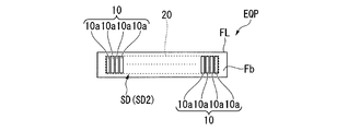
- FIG. 2 is a diagram showing a partial configuration of the operation unit SD.
- FIG. 2 shows the configuration of the side detection unit SD2 provided on the side surface Fb as a representative, but the same description can be made for the other side detection units SD1, SD3, and SD4.
- a detection region 20 is provided almost at the center of the side surface Fb.
- the detection region 20 is a rectangular region formed in the longitudinal direction in a direction that coincides with the longitudinal direction of the side surface Fb.
- the side part detection part SD2 has the electrode 10 provided in the detection area 20.
- the electrode 10 has a plurality of surface-side electrodes 10 a arranged in the longitudinal direction of the detection region 20.
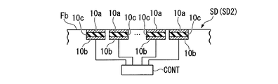
- FIG. 3 is a cross-sectional view showing the configuration of the side detection part SD2.
- the configuration of the side detection unit SD ⁇ b> 2 provided on the side surface Fb is shown as a representative. Is possible.
- each surface-side electrode 10a is disposed so as to be flush with other portions of the side surface Fb. Moreover, each surface side electrode 10a is arrange
- the capacitance between the surface-side electrode 10a and the internal-side electrode 10b arranged in the contacted part of the electrode 10 changes. Yes. Further, when the contact state of the user's finger or the like that has been in contact with a part of the detection region 20 is released, the capacitance between the surface side electrode 10a and the internal side electrode 10b returns to the original state. ing.
- the side detection unit SD2 is configured such that the capacitance of the contact portion of the electrode 10 changes locally. Such a change in capacitance is transmitted to the control device CONT.
- the control device CONT can calculate the presence / absence of contact from outside and the contact position by detecting the change in capacitance. For example, when the user moves the contact portion along the detection region 20, the position at which the capacitance changes moves with the movement of the contact portion.
- the control device CONT can also detect the movement (movement direction, movement distance, and movement speed) of the position where the capacitance changes.
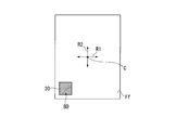
- FIG. 4 is a diagram when the portable information terminal EQP is viewed from the back surface Ff side.
- a back surface detection unit BD is provided on the back surface Ff of the portable information terminal EQP.
- the back surface detection unit BD has a back electrode 30 exposed on the surface of the back surface Ff.
- the back electrode 30 is disposed in the lower left corner of the back surface Ff in the drawing.
- the back electrode 30 is formed in a rectangle (for example, a square) when viewed from the back side.
- FIG. 4 shows a central portion (reference position) C of the back surface Ff.
- the back electrode 30 is disposed only on one side (left side) in the left-right direction (first direction) R1 in the drawing with the central portion C set on the back surface Ff as a reference, and is disposed on the other side (right side). It has no configuration. As described above, the back electrode 30 is formed in an asymmetric shape between the left side and the right side in the first direction R1 with respect to the central portion C.
- the back electrode 30 is disposed only on one side (lower side) of the vertical direction (second direction) R2 in the drawing with the central portion C set on the back surface Ff as a reference, and on the other side (upper side). The configuration is not arranged.
- the back electrode 30 is formed in a shape that is asymmetric between the lower side and the upper side of the second direction R2 with respect to the central portion C.
- FIG. 5 is a diagram illustrating a cross-sectional configuration of the back surface detection unit BD.
- the back surface detection unit BD includes an insulating layer 31 and an internal electrode 32 on the lower layer side of the back electrode 30.
- the back surface detection unit BD has a capacitance electrode that detects a capacitance formed between the back electrode 30 and the internal electrode 32. Each capacitance electrode is connected to the control device CONT.
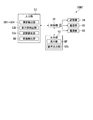
- FIG. 6 is a block diagram showing the configuration of the control device CONT.
- the control device CONT includes a control unit 51, an input unit 52, an output unit 53, a storage unit 54, a communication unit 55, and a power supply unit 56.
- the control unit 51 performs general arithmetic processing of the portable information terminal EQP.
- the input unit 52 is a part that inputs to the portable information terminal EQP.
- the back surface detection unit BD, the side part detection units SD1 to SD4, the display unit detection unit 52b, and as the input unit 52 for example, a sensor such as a posture detection unit 52c is provided.
- a voice input unit such as a microphone may be provided as the input unit 52, for example.
- the display part detection part 52b detects the presence or absence and the contact position of the touch in the touch panel TP.
- the posture detection unit 52c is a sensor that detects the posture of the portable information terminal EQP.
- a triaxial acceleration sensor, a gyro sensor, or a geomagnetic sensor is provided as the posture detection unit 52c.
- the output unit 53 outputs images and sounds. Examples of the output unit 53 include the display unit DP that displays an image, and an audio output unit 53b that outputs audio such as a speaker (not shown).
- the storage unit 54 stores the calculation results by the control unit 51, input information to be input to the input unit 52, output information to be output by the output unit 53 (eg, image data, audio data), information to be communicated via the communication unit 55, and the like.
- the communication unit 55 is configured to be able to communicate information with the outside by at least one of a wired method and a wireless method.
- the power supply unit 56 is provided with a power supply for supplying power to the portable information terminal EQP. Examples of the power supply unit 56 include a battery and a battery.
- the capacitance between the contacted portion of the back electrode 30 and the internal electrode 32 changes. Further, when the contact state of the user's hand or the like that has been in contact with the back electrode 30 is released, the capacitance between the back electrode 30 and the internal electrode 32 returns to the original state. The larger the contact area with the back electrode 30, the greater the amount of change in capacitance.
- FIGS. 7 and 8 are diagrams showing a contact area between the palm of the user and the back surface Ff of the portable information terminal EQP when the user holds the portable information terminal EQP by hand.
- 7 shows a case where the user holds portable information terminal EQP with the right hand
- FIG. 8 shows a case where the user holds portable information terminal EQP with the left hand.
- the contact area 41 tends to be wider on the right side in the first direction R1 than on the left side.
- the palm of the user's right hand contacts a part of the back electrode 30 disposed on the left side in the first direction R1.
- the left side of the first direction R1 tends to have a wider contact area 42 than the right side.
- the palm of the left hand of the user contacts almost the entire surface of the back electrode 30 disposed on the left side in the first direction R1.
- the capacitance changes according to the size of the contact area between the back electrode 30 and the user's hand. For this reason, for example, in the case shown in FIG. 7 (when the hand contacts a part of the back electrode 30), as compared with the case shown in FIG. 8 (when the hand contacts all of the back electrode 30), The amount of change in capacity is small.
- Such a change in capacitance is transmitted to the control device CONT.
- the control device CONT determines whether the user's hand holding the portable information terminal EQP is left or right by detecting the amount of change in capacitance.
- the method of holding the portable information terminal EQP differs depending on the user. For example, contrary to the above example, when holding the portable information terminal EQP with the right hand, as shown in FIG. 8, when touching almost the entire surface of the back electrode 30 and holding the portable information terminal EQP with the left hand As shown in FIG. 7, the case where it contacts a part of back electrode 30 etc. can be assumed. For this reason, you may enable it to set which hand hold
- the portable information terminal EQP includes the back electrode 30 that is provided on the back surface Ff of the housing FL and detects the presence / absence of contact and the contact position on the back surface Ff. Therefore, the presence / absence of contact between the user's hand and the back electrode 30 and the contact position when the user holds the portable information terminal EQP can be detected. Since the size of the contact portion can be detected by this detection, it is possible to determine whether the user is holding the portable information terminal EQP with the left or right hand based on the result.
- the technical scope of the present invention is not limited to the above-described embodiment, and appropriate modifications can be made without departing from the spirit of the present invention.
- the structure which detects a capacitance changing by contact as a structure of the back surface detection part BD
- a configuration for example, a resistive film type touch sensor
- a configuration of the back surface detection unit BD in addition to a configuration in which an electrode is provided, a configuration in which no electrode is provided, such as a surface acoustic wave method or an infrared method, may be used.
- the configuration in which the touch panel TP is provided on the surface of the display unit DP has been described as an example.
- the configuration is not limited thereto, and a configuration in which the touch panel TP is not provided may be used. Absent.
- the operation is performed using the side detection units SD1 to SD4 provided in the operation unit SD. With this configuration, since high operability can be obtained without providing the touch panel TP, the cost of the portable information terminal can be reduced.
- the back electrode 30 of the back surface detection unit BD is formed in a rectangular shape, and one configuration is arranged at the corner of the back surface Ff.
- the present invention is not limited to this. Other shapes may be used for the shape, arrangement, and number of the back electrodes 30.
- FIGS. 9 to 16 are diagrams (rear views) showing the configuration of the rear surface Ff of the portable information terminal EQP.
- the back electrode 30a is formed in a triangle when viewed from the back side.
- the back electrode 30a is formed in a strip shape from the left end to the right end in the figure so as to straddle the central portion in the first direction R1.
- the back electrode 30a is formed so as to become gradually thinner from the left side to the right side in the drawing in the first direction R1.
- the back electrode 30a is configured to spread to the left side in the first direction R1 with the central portion C as a reference. For this reason, the back electrode 30a is formed in an asymmetric shape between the left side and the right side in the first direction R1 with respect to the central portion C. Further, the back electrode 30a is disposed only on the lower side of the second direction R2 with respect to the central portion C, and is not disposed on the upper side. Thus, the back electrode 30a is formed in a shape that is asymmetric between the lower side and the upper side of the second direction R2 with respect to the central portion C.
- the configuration in which the back electrode 30 is disposed on the lower side of the second direction R2 in the drawing is taken as an example.
- the configuration is not limited to this, for example, as shown by a broken line portion 30b in the drawing.
- the configuration may be arranged on the upper side in the drawing in the second direction R2.
- the first direction R1 can be configured to gradually narrow from the right side to the left side in the drawing.
- the back surface detection unit BD has a back electrode 30a and a back electrode 30b.
- the back electrode 30a and the back electrode 30b are each formed in a triangle when viewed from the back side.
- the back electrode 30a and the back electrode 30b are formed in a band shape from the left end to the right end in the figure so as to straddle the central portion in the first direction R1.
- the back electrode 30a is formed so as to become gradually narrower from the left side to the right side in the drawing in the first direction R1. Further, the back electrode 30b is formed so as to gradually become thinner from the right side to the left side in the drawing in the first direction R1.
- the back electrode 30a and the back electrode 30b are arranged side by side in the second direction R2 so that the oblique sides of each other face each other in parallel.
- the back surface detection unit BD has a configuration in which the back electrode 30a extends to the left side of the first direction R1 with respect to the central part C, and the back electrode 30b has a configuration in the first direction R1 with respect to the central part C. It has a configuration that spreads to the right. For this reason, the back electrode 30a and the back electrode 30b are formed in an asymmetric shape between the left side and the right side in the first direction R1 with respect to the central portion C. Further, the back electrode 30a and the back electrode 30b are arranged only on the lower side of the second direction R2 with respect to the central portion C, and are not arranged on the upper side. As described above, the back electrode 30a and the back electrode 30b are formed in an asymmetric shape between the lower side and the upper side of the second direction R2 with respect to the central portion C.
- the configuration in which the back electrode 30 is arranged on the lower side in the second direction R ⁇ b> 2 is taken as an example.
- the configuration is not limited to this, and the second electrode is similar to the case illustrated in FIG. 9.
- the configuration may be arranged on the upper side in the drawing in the direction R2.
- the back surface detection unit BD has a back electrode 30a and a back electrode 30b.
- the back electrode 30a and the back electrode 30b are each formed in a triangle when viewed from the back side.
- the back electrode 30a is formed in a strip shape from the left end to the right end in the figure so as to straddle the central portion in the first direction R1.
- the back electrode 30a is disposed along the lower side in the figure of the back surface Ff formed in a rectangular shape.
- the back electrode 30a is formed so as to become gradually thinner from the left side to the right side in the drawing in the first direction R1.
- the back electrode 30b is formed in a strip shape from the lower end to the upper end in the figure so as to straddle the central portion in the second direction R2.
- the back electrode 30b is disposed along the left side of the back surface Ff in the drawing.
- the back electrode 30b is formed so as to become gradually narrower from the lower side to the upper side in the drawing in the second direction R2.
- the back electrode 30a and the back electrode 30b are disposed close to each other at the lower left corner of the back Ff.
- the back electrode 30a and the back electrode 30b may be configured to be connected at the lower left corner in the figure, or may be configured to be separated. Note that the detection sensitivity is improved when the back electrode 30a and the back electrode 30b are separated.
- the back surface detection unit BD has a configuration in which the back electrode 30a extends to the left side in the first direction R1 with the center portion C as a reference.
- the back electrode 30b is disposed only on the left side in the figure with respect to the central portion C, and is not disposed on the right side. For this reason, the back electrode 30a and the back electrode 30b are formed in an asymmetric shape between the left side and the right side in the first direction R1 with respect to the central portion C.
- the back electrode 30a is disposed only on the lower side in the figure with respect to the central portion C, and is not disposed on the upper side. Further, the back electrode 30b is configured to expand downward in the second direction R2 with the center portion C as a reference. As described above, the back electrode 30a and the back electrode 30b are formed in an asymmetric shape between the lower side and the upper side of the second direction R2 with respect to the central portion C.
- the back surface detection unit BD includes a back electrode 30a.
- the back electrode 30a is formed in a triangle when viewed from the back side.
- the back electrode 30a is formed in a strip shape so as to straddle the central portion C from the lower left side to the upper right side of the back surface Ff.
- the back electrode 30a is formed so that the back electrode 30a gradually becomes thinner from the lower left side to the upper right side in the figure.
- the back surface detection unit BD has a configuration in which the back electrode 30a extends from the lower left side to the upper right side of the back surface Ff with the center C as a reference. Further, the back electrode 30a is disposed only on the lower left side and the upper right side of the back surface Ff with respect to the central portion C, and is not disposed on the lower right side and the upper left side of the back surface Ff. For this reason, the back electrode 30a is formed in an asymmetric shape between the left side and the right side in the first direction R1 with respect to the central portion C. The back electrode 30a is formed in an asymmetric shape between the lower side and the upper side of the second direction R2 with respect to the central portion C.
- the back electrode 30b and the back electrode 30c are added to the configuration shown in FIG.
- the back electrode 30b and the back electrode 30c are formed in a triangle shape when viewed from the back side, and are formed in a strip shape so as to straddle the central portion in the second direction R2 from the upper side to the lower side in the figure.
- the back electrode 30b and the back electrode 30c are formed so as to become gradually thinner from the upper side to the lower side in the drawing.
- the back electrode 30a, the back electrode 30b, and the back electrode 30c are formed in an asymmetric shape with respect to the left side and the right side in the first direction R1 with respect to the central portion C.
- the back electrode 30a, the back electrode 30b, and the back electrode 30c are formed in a shape that is asymmetric between the lower side and the upper side of the second direction R2 with respect to the central portion C.
- the back surface detection unit BD includes a back electrode 30a and a back electrode 30b. Both the back electrode 30a and the back electrode 30b are formed in a rectangle (square) when viewed from the back side.
- the back electrode 30a is provided at the same position as the back electrode 30 in the above embodiment.
- the back electrode 30b is provided at the upper right corner of the back surface Ff.
- the back electrode 30a and the back electrode 30b are formed in an asymmetric shape between the left side and the right side in the first direction R1 with respect to the central portion C. Further, the back electrode 30a and the back electrode 30b are formed in an asymmetric shape between the lower side and the upper side of the second direction R2 with respect to the central portion C.
- the back surface detection unit BD includes a back electrode 30a, a back electrode 30b, and a back electrode 30c.
- the back electrode 30a, the back electrode 30b, and the back electrode 30c are each formed in a rectangle (square) when viewed from the back side.
- the dimensions of the back electrode 30a, the back electrode 30b, and the back electrode 30c at least one of the dimensions may be different.
- the back electrode 30a is provided at the same position as the back electrode 30 in the above embodiment (lower left corner of the back surface Ff).
- the back electrode 30b is provided at the upper left corner of the back surface Ff.
- the back electrode 30c is provided at the lower right corner of the back surface Ff.
- the back electrode 30d may be arranged at the upper right corner (position indicated by a broken line in the drawing) of the back surface Ff.
- the back electrode 30a, the back electrode 30b, and the back electrode 30c are formed in an asymmetric shape with respect to the left side and the right side in the first direction R1 with respect to the central portion C.
- the back electrode 30a, the back electrode 30b, and the back electrode 30c are formed in a shape that is asymmetric between the lower side and the upper side of the second direction R2 with respect to the center portion C.
- the back surface detection unit BD has a back electrode 30a, a back electrode 30b, and a back electrode 30c.
- the back electrode 30a is formed in a rectangle (square) when viewed from the back side.
- the back electrode 30b and the back electrode 30c are formed in a triangle when viewed from the back side.
- the back electrode 30c is formed in a strip shape so as to straddle the central portion in the second direction R2 from the upper side to the lower side in the drawing.
- the back electrode 30c is disposed along the left side of the back surface Ff, and is formed so as to become gradually thinner from the upper side to the lower side in the drawing.
- the back electrode 30b is disposed along the lower side of the back surface Ff, and is formed in a strip shape so as to straddle the central portion in the first direction R1 from the right side to the left side in the drawing.
- the back electrode 30b is formed so as to become gradually thinner from the right side to the left side in the drawing.
- the back electrode 30b and the back electrode 30a may be connected or separated.
- the back electrode 30c and the back electrode 30a may be connected or separated.
- the back electrode 30a, the back electrode 30b, and the back electrode 30c are formed in an asymmetric shape with respect to the left side and the right side in the first direction R1 with respect to the central portion C.
- the back electrode 30a, the back electrode 30b, and the back electrode 30c are formed in a shape that is asymmetric between the lower side and the upper side of the second direction R2 with respect to the center portion C.
- EQP mobile information terminal FL ... housing DP ... display unit CONT ... control device PN ... display panel Fe ... display surface Ff ... rear surface BD ... rear surface detection unit C ... central portion R1 ... first direction R2 ... second direction 20 ... detection Area 30 ... Back electrode 30a-30d ... Back electrode 31 ... Insulating layer 32 ... Internal electrode 41 ... Contact area 42 ... Contact area
Landscapes
- Engineering & Computer Science (AREA)
- General Engineering & Computer Science (AREA)
- Theoretical Computer Science (AREA)
- Human Computer Interaction (AREA)
- Physics & Mathematics (AREA)
- General Physics & Mathematics (AREA)
- Computer Networks & Wireless Communication (AREA)
- Signal Processing (AREA)
- User Interface Of Digital Computer (AREA)
Abstract
電子機器は、第一面及び前記第一面の背面に設けられた第二面を有する筐体と、前記筐体のうち前記第一面に設けられた表示部と、前記筐体のうち前記第二面に設けられ、前記第二面における接触の有無及び接触位置を検出する検出部と、前記検出部とユーザーの手との接触に基づいて、前記筐体を保持する前記ユーザーの手が左右のいずれであるかを判別する制御装置と、を備える。
Description
本発明は、電子機器に関する。
本願は、2011年12月5日に出願された日本国特願2011-266144号に基づき優先権を主張し、その内容をここに援用する。
本願は、2011年12月5日に出願された日本国特願2011-266144号に基づき優先権を主張し、その内容をここに援用する。
携帯電話や携帯情報端末などの電子機器として、例えば特許文献1が知られている。特許文献1に示すような電子機器においては、例えば板状に設けられた筐体の一の面に表示部が設けられており、この一の面のうち表示部の周囲の領域や筐体の側部などに操作部が設けられた構成が知られている。
しかしながら、従来の電子機器においては、ユーザーの操作性に改善の余地がある。本発明の態様は、操作性を一層向上させた電子機器を提供する。
本発明の態様に従えば、第一面及び前記第一面の背面に設けられた第二面を有する筐体と、前記筐体のうち前記第一面に設けられた表示部と、前記筐体のうち前記第二面に設けられ、前記第二面における接触の有無及び接触位置を検出する検出部と、前記検出部とユーザーの手との接触に基づいて、前記筐体を保持する前記ユーザーの手が左右のいずれであるかを判別する制御装置と、を備える電子機器が提供される。
本発明の態様によれば、操作性を一層向上させた電子機器を提供することができる。
以下、図面を参照して、本発明の実施形態を説明する。
図1は、本実施形態に係る携帯情報端末EQPの構成を示す斜視図である。
図1に示すように、携帯情報端末EQPは、筐体FL、表示部DP、操作部SD及び制御装置CONTを有している。
図1は、本実施形態に係る携帯情報端末EQPの構成を示す斜視図である。
図1に示すように、携帯情報端末EQPは、筐体FL、表示部DP、操作部SD及び制御装置CONTを有している。
筐体FLは、例えば矩形の板状に形成されており、表示部DP及び操作部SDを保持する。
表示部DPは、筐体FLのうち板面に設けられている。筐体FLのうちこの表示部DPが設けられる面を、以下、表示面Feと表記する。表示部DPは、例えば液晶装置や有機EL装置などを有する表示パネルPNを有している。表示パネルPNが設けられる表示領域には、例えばタッチパネルTPが設けられている。
表示部DPは、筐体FLのうち板面に設けられている。筐体FLのうちこの表示部DPが設けられる面を、以下、表示面Feと表記する。表示部DPは、例えば液晶装置や有機EL装置などを有する表示パネルPNを有している。表示パネルPNが設けられる表示領域には、例えばタッチパネルTPが設けられている。
操作部SDは、筐体FLのうち表示面Feを囲む4辺に相当する4つの側面Fa~Fdに設けられている。操作部SDは、側面Faに設けられた側部検出部SD1、側面Fbに設けられた側部検出部SD2、側面Fcに設けられた側部検出部SD3及び側面Fdに設けられた側部検出部SD4を有している。操作部SDは、側部検出部SD1~SD4において外部からの(例えばユーザーの)接触の有無及び接触位置を検出する。
図2は、操作部SDの一部の構成を示す図である。図2には、側面Fbに設けられた側部検出部SD2の構成を代表させて示しているが、他の側部検出部SD1、SD3及びSD4についても同様の説明が可能である。
図2に示すように、側面Fbのほぼ中央部には、検出領域20が設けられている。検出領域20は、側面Fbの長手方向に一致する方向に長手に形成された矩形の領域である。
側部検出部SD2は、検出領域20に設けられた電極10を有している。電極10は、検出領域20の長手方向に並べられた複数の表面側電極10aを有している。
図3は、側部検出部SD2の構成を示す断面図である。図3には、図2と同様に、側面Fbに設けられた側部検出部SD2の構成を代表させて示しているが、他の側部検出部SD1、SD3及びSD4についても同様の説明が可能である。
図3に示すように、各表面側電極10aは、側面Fbの他の部分と面一状態となるように配置されている。また、各表面側電極10aは、それぞれ内部側電極10bと対向するように配置されている。表面側電極10aと内部側電極10bとの間には、それぞれ誘電体10cが配置されている。このように、電極10は、表面側電極10aと内部側電極10bとの間で形成される容量電極を有している。各容量電極は、それぞれ制御装置CONTに接続されている。
例えばユーザーの指などが検出領域20の一部分に接触すると、電極10のうち接触された部分に配置される表面側電極10aと内部側電極10bとの間の静電容量が変化するようになっている。また、検出領域20の一部分に接触していたユーザーの指などの接触状態が解除されると、表面側電極10aと内部側電極10bとの間の静電容量が元の状態に戻るようになっている。
このように、側部検出部SD2では、電極10における接触部分の静電容量が局所的に変化するように構成されている。このような静電容量の変化は、制御装置CONTに送信されるようになっている。制御装置CONTでは、この静電容量の変化を検出することにより、外部からの接触の有無及び接触位置を算出可能となっている。なお、例えばユーザーが検出領域20に沿って接触部分を移動させる場合、静電容量の変化する位置が接触部分の移動に伴って移動する。制御装置CONTでは、この静電容量の変化する位置の移動(移動方向、移動距離及び移動速度)についても検出可能となっている。
図4は、携帯情報端末EQPを背面Ff側から見たときの図である。
図4に示すように、携帯情報端末EQPの背面Ffには、背面検出部BDが設けられている。背面検出部BDは、背面Ffの表面に露出する背面電極30を有している。背面電極30は、背面Ffのうち図中左下の角部に配置されている。背面電極30は、背面側から見て矩形(例えば正方形)に形成されている。
図4に示すように、携帯情報端末EQPの背面Ffには、背面検出部BDが設けられている。背面検出部BDは、背面Ffの表面に露出する背面電極30を有している。背面電極30は、背面Ffのうち図中左下の角部に配置されている。背面電極30は、背面側から見て矩形(例えば正方形)に形成されている。
図4には、背面Ffの中央部(基準位置)Cが示されている。背面電極30は、背面Ffに設定される中央部Cを基準として図中左右方向(第一方向)R1の一方側(左側)にのみ配置されており、他方側(右側)には配置されていない構成となっている。このように、背面電極30は、中央部Cを基準として第一方向R1の左側と右側とで非対称となる形状に形成されている。
また、背面電極30は、背面Ffに設定される中央部Cを基準として図中上下方向(第二方向)R2の一方側(下側)にのみ配置されており、他方側(上側)には配置されていない構成となっている。このように、背面電極30は、中央部Cを基準として第二方向R2の下側と上側とで非対称となる形状に形成されている。
図5は、背面検出部BDの断面構成を示す図である。
図5に示すように、背面検出部BDは、背面電極30の下層側に、絶縁層31及び内部電極32を有している。背面検出部BDは、背面電極30と内部電極32との間で形成される容量を検出する容量電極を有している。各容量電極は、それぞれ制御装置CONTに接続されている。
図5に示すように、背面検出部BDは、背面電極30の下層側に、絶縁層31及び内部電極32を有している。背面検出部BDは、背面電極30と内部電極32との間で形成される容量を検出する容量電極を有している。各容量電極は、それぞれ制御装置CONTに接続されている。
図6は、制御装置CONTの構成を示すブロック図である。
図6に示すように、制御装置CONTは、制御部51、入力部52、出力部53、記憶部54、通信部55及び電源部56を有している。
図6に示すように、制御装置CONTは、制御部51、入力部52、出力部53、記憶部54、通信部55及び電源部56を有している。
制御部51は、携帯情報端末EQPの統括的な演算処理を行う。
入力部52は、携帯情報端末EQPに対して入力を行う部分である。入力部52としては、上記の背面検出部BDや側部検出部SD1~SD4、表示部検出部52b、また、入力部52として、例えば姿勢検出部52cなどのセンサが設けられている。この他、入力部52として、例えばマイクなどの不図示の音声入力部が設けられていても構わない。
入力部52は、携帯情報端末EQPに対して入力を行う部分である。入力部52としては、上記の背面検出部BDや側部検出部SD1~SD4、表示部検出部52b、また、入力部52として、例えば姿勢検出部52cなどのセンサが設けられている。この他、入力部52として、例えばマイクなどの不図示の音声入力部が設けられていても構わない。
表示部検出部52bは、タッチパネルTPにおける接触の有無及び接触位置を検出する。姿勢検出部52cは、携帯情報端末EQPの姿勢を検出するセンサである。姿勢検出部52cとしては、例えば3軸加速度センサやジャイロセンサ、地磁気センサなどが設けられている。
出力部53は、画像や音声などを出力する。出力部53としては、例えば画像を表示する上記の表示部DPや、スピーカー(不図示)のような音声を出力する音声出力部53bなどが挙げられる。記憶部54は、制御部51による演算結果や入力部52に入力させる入力情報、出力部53によって出力させる出力情報(例、画像データ、音声データ)、通信部55を介して通信する情報などを記憶する。
通信部55は、外部との間で有線方式及び無線方式のうち少なくとも一方の方式によって情報の通信が可能となるように構成されている。
電源部56は、携帯情報端末EQPに電力を供給するための電源が配置されている。電源部56としては、例えば電池やバッテリー等が挙げられる。
電源部56は、携帯情報端末EQPに電力を供給するための電源が配置されている。電源部56としては、例えば電池やバッテリー等が挙げられる。
例えばユーザーの手などが背面電極30に接触すると、背面電極30のうち接触された部分と内部電極32との間の静電容量が変化する。また、背面電極30に接触していたユーザーの手などの接触状態が解除されると、背面電極30と内部電極32との間の静電容量が元の状態に戻るようになっている。背面電極30に対する接触面積が大きいほど、静電容量の変化量は大きくなる。
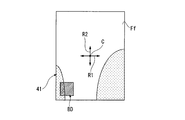
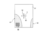
図7及び図8は、ユーザーが携帯情報端末EQPを手で保持した場合において、ユーザーの手のひらと携帯情報端末EQPの背面Ffとの接触領域を示す図である。なお、図7はユーザーが右手で携帯情報端末EQPを保持した場合を示しており、図8はユーザーが左手で携帯情報端末EQPを保持した場合を示している。
図7に示すように、ユーザーが右手で携帯情報端末EQPを保持する場合、例えば第一方向R1の右側の方が、左側に比べて接触領域41が広くなる傾向にある。この場合、ユーザーの右手の手のひらは、第一方向R1の左側に配置されている背面電極30の一部に接触する。
一方、図8に示すように、ユーザーが左手で携帯情報端末EQPを保持する場合、例えば第一方向R1の左側の方が、右側に比べて接触領域42が広くなる傾向にある。この場合、ユーザーの左手の手のひらは、第一方向R1の左側に配置されている背面電極30のほぼ全面に接触する。
背面検出部BDでは、背面電極30とユーザーの手との接触領域の大きさに応じて静電容量が変化する。このため、例えば図7に示す場合(手が背面電極30の一部に接触する場合)には、図8に示す場合(手が背面電極30の全部に接触する場合)に比べて、静電容量の変化量は小さくなる。
このような静電容量の変化は、制御装置CONTに送信される。制御装置CONTでは、この静電容量の変化量を検出することにより、携帯情報端末EQPを保持するユーザーの手が左右のいずれであるかを判別する。なお、ユーザーによって携帯情報端末EQPの保持の仕方が異なる場合がある。例えば、上記の例とは逆に、右手で携帯情報端末EQPを保持する場合には、図8に示すように背面電極30のほぼ全面に接触し、左手で携帯情報端末EQPを保持する場合には、図7に示すように背面電極30の一部に接触する場合などが想定されうる。このため、背面検出部BDの検出結果に対して、携帯情報端末EQPを保持する手がいずれであるかを設定できるようにしても構わない。
以上のように、本実施形態に係る携帯情報端末EQPは、筐体FLの背面Ffに設けられ、背面Ffにおける接触の有無及び接触位置を検出する背面電極30を備える。そのため、ユーザーが携帯情報端末EQPを保持する際におけるユーザーの手と背面電極30との接触の有無及び接触位置を検出することができる。この検出により、接触部分の大きさを検出することができるので、この結果をもとにユーザーが携帯情報端末EQPを左右のいずれの手で保持しているかを判別することが可能となる。
本発明の技術範囲は上記実施形態に限定されるものではなく、本発明の趣旨を逸脱しない範囲で適宜変更を加えることができる。
上記実施形態においては、背面検出部BDの構成として、接触によって静電容量が変化するのを検出する構成を例に挙げて説明したが、これに限られることは無い。例えば、接触によって電圧が変化するのを検出する構成(例えば、抵抗膜方式のタッチセンサ等)としても構わない。また、背面検出部BDの構成として、電極を設ける構成の他、例えば表面弾性波方式や赤外線方式など、電極を設けない構成であっても構わない。
上記実施形態においては、背面検出部BDの構成として、接触によって静電容量が変化するのを検出する構成を例に挙げて説明したが、これに限られることは無い。例えば、接触によって電圧が変化するのを検出する構成(例えば、抵抗膜方式のタッチセンサ等)としても構わない。また、背面検出部BDの構成として、電極を設ける構成の他、例えば表面弾性波方式や赤外線方式など、電極を設けない構成であっても構わない。
また、上記実施形態においては、表示部DPの表面にタッチパネルTPが設けられた構成を例に挙げて説明したが、これに限られることは無く、タッチパネルTPが設けられない構成であっても構わない。この場合、操作部SDに設けられる側部検出部SD1~SD4を用いて操作する構成となる。この構成により、タッチパネルTPを設けなくても高い操作性を得ることができるため、携帯情報端末の低コスト化を図ることができる。
また、上記実施形態において、背面検出部BDの背面電極30が矩形に形成され、背面Ffの角部に1つ配置された構成を例に挙げて説明したが、これに限られることは無く、背面電極30の形状や配置、個数については、他の形態であっても構わない。
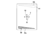
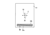
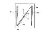
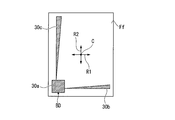
図9~図16は、携帯情報端末EQPの背面Ffの構成を示す図(背面図)である。
図9に示す構成において、背面電極30aは、背面側から見て三角形に形成されている。この背面電極30aは、第一方向R1の中央部を跨ぐように図中左側端部から右側端部にかけて帯状に形成されている。また、背面電極30aは、第一方向R1の図中左側から右側へ向けて徐々に細くなるように形成されている。
図9に示す構成において、背面電極30aは、背面側から見て三角形に形成されている。この背面電極30aは、第一方向R1の中央部を跨ぐように図中左側端部から右側端部にかけて帯状に形成されている。また、背面電極30aは、第一方向R1の図中左側から右側へ向けて徐々に細くなるように形成されている。
このように背面電極30aは、中央部Cを基準として第一方向R1の左側に広がった構成となっている。このため、背面電極30aは、中央部Cを基準として第一方向R1の左側と右側とで非対称となる形状に形成されている。また、背面電極30aは、中央部Cを基準として第二方向R2の下側にのみ配置されており、上側には配置されていない構成となっている。このように、背面電極30aは、中央部Cを基準として第二方向R2の下側と上側とで非対称となる形状に形成されている。
なお、図9では、背面電極30が第二方向R2の図中下側に配置された構成を例に挙げているが、これに限られることは無く、例えば図中破線部30bに示すように、第二方向R2の図中上側に配置された構成であっても構わない。この場合、例えば、第一方向R1について、図中右側から左側へ向けて徐々に細くなるように形成された構成とすることができる。
また、図10に示す構成において、背面検出部BDは、背面電極30a及び背面電極30bを有している。背面電極30a及び背面電極30bは、背面側から見てそれぞれ三角形に形成されている。これら背面電極30a及び背面電極30bは、第一方向R1の中央部を跨ぐように図中左側端部から右側端部にかけて帯状に形成されている。
一方、背面電極30aは、第一方向R1の図中左側から右側へ向けて徐々に細くなるように形成されている。また、背面電極30bは、第一方向R1の図中右側から左側へ向けて徐々に細くなるように形成されている。背面電極30a及び背面電極30bは、互いの斜辺同士が平行に対向するように第二方向R2に並んで配置されている。
このように、背面検出部BDは、背面電極30aが中央部Cを基準として第一方向R1の左側に広がった構成となっており、背面電極30bが中央部Cを基準として第一方向R1の右側に広がった構成となっている。このため、背面電極30a及び背面電極30bは、中央部Cを基準として第一方向R1の左側と右側とで非対称となる形状に形成されている。また、背面電極30a及び背面電極30bは、中央部Cを基準として第二方向R2の下側にのみ配置されており、上側には配置されていない構成となっている。このように、背面電極30a及び背面電極30bは、中央部Cを基準として第二方向R2の下側と上側とで非対称となる形状に形成されている。
なお、図10では、背面電極30が第二方向R2の図中下側に配置された構成を例に挙げているが、これに限られることは無く、図9に示す場合と同様、第二方向R2の図中上側に配置された構成であっても構わない。
また、図11に示す構成において、背面検出部BDは、背面電極30a及び背面電極30bを有している。背面電極30a及び背面電極30bは、背面側から見てそれぞれ三角形に形成されている。
背面電極30aは、第一方向R1の中央部を跨ぐように図中左側端部から右側端部にかけて帯状に形成されている。背面電極30aは、矩形に形成された背面Ffのうち図中下側の辺に沿って配置されている。背面電極30aは、第一方向R1の図中左側から右側へ向けて徐々に細くなるように形成されている。
背面電極30bは、第二方向R2の中央部を跨ぐように図中下側端部から上側端部にかけて帯状に形成されている。背面電極30bは、背面Ffのうち図中左側の辺に沿って配置されている。背面電極30bは、第二方向R2の図中下側から上側へ向けて徐々に細くなるように形成されている。
背面電極30a及び背面電極30bは、背面Ffのうち図中左下の角部において近接して配置されている。背面電極30a及び背面電極30bは、この図中左下の角部において接続されている構成であっても構わないし、分離されている構成であっても構わない。なお、背面電極30aと背面電極30bとの間は、分離されている場合の方が、検出感度が向上する。
このように、背面検出部BDは、背面電極30aが中央部Cを基準として第一方向R1の左側に広がった構成となっている。背面電極30bは、中央部Cを基準として図中左側にのみ配置されており、右側には配置されていない。このため、背面電極30a及び背面電極30bは、中央部Cを基準として第一方向R1の左側と右側とで非対称となる形状に形成されている。
また、背面電極30aは、中央部Cを基準として図中下側にのみ配置されており、上側には配置されていない。また、背面電極30bが中央部Cを基準として第二方向R2の下側に広がった構成となっている。このように、背面電極30a及び背面電極30bは、中央部Cを基準として第二方向R2の下側と上側とで非対称となる形状に形成されている。
また、図12に示す構成において、背面検出部BDは、背面電極30aを有している。
背面電極30aは、背面側から見て三角形に形成されている。背面電極30aは、背面Ffの左下側から右上側にかけて中央部Cを跨ぐように帯状に形成されている。背面電極30aは、背面電極30aは、図中左下側から右上側へ向けて徐々に細くなるように形成されている。
背面電極30aは、背面側から見て三角形に形成されている。背面電極30aは、背面Ffの左下側から右上側にかけて中央部Cを跨ぐように帯状に形成されている。背面電極30aは、背面電極30aは、図中左下側から右上側へ向けて徐々に細くなるように形成されている。
このように、背面検出部BDは、背面電極30aが中央部Cを基準として背面Ffの左下側から右上側に広がった構成となっている。また、背面電極30aは、中央部Cを基準として背面Ffの左下側及び右上側にのみ配置されており、背面Ffの右下側及び左上側には配置されていない。このため、背面電極30aは、中央部Cを基準として第一方向R1の左側と右側とで非対称となる形状に形成されている。また、背面電極30aは、中央部Cを基準として第二方向R2の下側と上側とで非対称となる形状に形成されている。
また、図13に示す構成においては、図12に示す構成に対して、背面電極30b及び背面電極30cを加えた構成となっている。背面電極30b及び背面電極30cは、背面側から見て三角形に形成されており、図中上側から下側へかけて第二方向R2の中央部を跨ぐように帯状に形成されている。背面電極30b及び背面電極30cは、図中上側から下側にかけて徐々に細くなるように形成されている。
この場合においても、背面電極30a、背面電極30b及び背面電極30cは、中央部Cを基準として第一方向R1の左側と右側とで非対称となる形状に形成されている。また、背面電極30a、背面電極30b及び背面電極30cは、中央部Cを基準として第二方向R2の下側と上側とで非対称となる形状に形成されている。
また、図14に示す構成において、背面検出部BDは、背面電極30a及び背面電極30bを有している。背面電極30a及び背面電極30bは、背面側から見て共に矩形(正方形)に形成されている。背面電極30aは、上記実施形態における背面電極30と同一の位置に設けられている。背面電極30bは、背面Ffの右上の角部に設けられている。
この場合においても、背面電極30a及び背面電極30bは、中央部Cを基準として第一方向R1の左側と右側とで非対称となる形状に形成されている。また、背面電極30a及び背面電極30bは、中央部Cを基準として第二方向R2の下側と上側とで非対称となる形状に形成されている。
また、図15に示す構成において、背面検出部BDは、背面電極30a、背面電極30b及び背面電極30cを有している。背面電極30a、背面電極30b及び背面電極30cは、背面側から見てそれぞれ矩形(正方形)に形成されている。背面電極30a、背面電極30b及び背面電極30cの寸法については、少なくとも1つが異なる寸法であっても構わない。
背面電極30aは、上記実施形態における背面電極30と同一の位置(背面Ffの左下の角部)に設けられている。背面電極30bは、背面Ffの左上の角部に設けられている。背面電極30cは、背面Ffの右下の角部に設けられている。なお、背面電極30a~30cのうちいずれか1つの代わりに、背面電極30dが背面Ffの右上の角部(図中破線で示す位置)に配置された構成であっても構わない。
この場合においても、背面電極30a、背面電極30b及び背面電極30c(背面電極30d)は、中央部Cを基準として第一方向R1の左側と右側とで非対称となる形状に形成されている。また、背面電極30a、背面電極30b及び背面電極30c(背面電極30d)は、中央部Cを基準として第二方向R2の下側と上側とで非対称となる形状に形成されている。
また、図16に示す構成において、背面検出部BDは、背面電極30a、背面電極30b及び背面電極30cを有している。背面電極30aは、背面側から見て矩形(正方形)に形成されている。背面電極30b及び背面電極30cは、背面側から見て三角形に形成されている。
背面電極30cは、図中上側から下側へかけて第二方向R2の中央部を跨ぐように帯状に形成されている。背面電極30cは、背面Ffの左側の辺に沿って配置されており、図中上側から下側にかけて徐々に細くなるように形成されている。背面電極30bは、背面Ffの下側の辺に沿って配置されており、図中右側から左側へかけて第一方向R1の中央部を跨ぐように帯状に形成されている。背面電極30bは、図中右側から左側にかけて徐々に細くなるように形成されている。背面電極30bと背面電極30aとの間は、接続されていても構わないし、分離されていても構わない。同様に、背面電極30cと背面電極30aとの間は、接続されていても構わないし、分離されていても構わない。
この場合においても、背面電極30a、背面電極30b及び背面電極30c(背面電極30d)は、中央部Cを基準として第一方向R1の左側と右側とで非対称となる形状に形成されている。また、背面電極30a、背面電極30b及び背面電極30c(背面電極30d)は、中央部Cを基準として第二方向R2の下側と上側とで非対称となる形状に形成されている。
EQP…携帯情報端末 FL…筐体 DP…表示部 CONT…制御装置 PN…表示パネル Fe…表示面 Ff…背面 BD…背面検出部 C…中央部 R1…第一方向 R2…第二方向 20…検出領域 30…背面電極 30a~30d…背面電極 31…絶縁層 32…内部電極 41…接触領域 42…接触領域
Claims (9)
- 第一面及び前記第一面の背面に設けられた第二面を有する筐体と、
前記筐体のうち前記第一面に設けられた表示部と、
前記筐体のうち前記第二面に設けられ、前記第二面における接触の有無及び接触位置を検出する検出部と、
前記検出部とユーザーの手との接触に基づいて、前記筐体を保持する前記ユーザーの手が左右のいずれであるかを判別する制御装置と、
を備える電子機器。 - 前記制御装置は、前記検出部と前記ユーザーの手との接触領域の大きさに基づいて、前記筐体を保持する前記ユーザーの手が左右のいずれであるかを判別する
請求項1に記載の電子機器。 - 前記検出部は、接触による静電容量の変化を検出する電極である
請求項1又は請求項2に記載の電子機器。 - 前記検出部は、前記第二面に設定される基準位置を基準として所定方向の一方側と他方側とで非対称となる形状に形成されている
請求項1から請求項3のうちいずれか一項に記載の電子機器。 - 前記検出部は、前記所定方向の一方側及び他方側のうち少なくとも一方に配置されている
請求項4に記載の電子機器。 - 前記検出部は、前記所定方向の一方側から他方側へ向けて帯状に形成されている
請求項4又は請求項5に記載の電子機器。 - 前記検出部は、前記所定方向の一方側から他方側へ向けて徐々に細くなるように形成されている
請求項6に記載の電子機器。 - 前記筐体は、一方向に長手となるように形成され、
前記所定方向は、前記一方向に交差する第一方向に設定される
請求項1から請求項7のうちいずれか一項に記載の電子機器。 - 前記筐体は、一方向に長手となるように形成され、
前記所定方向は、前記一方向に平行な第二方向に設定される
請求項1から請求項8のうちいずれか一項に記載の電子機器。
Applications Claiming Priority (2)
| Application Number | Priority Date | Filing Date | Title |
|---|---|---|---|
| JP2011266144 | 2011-12-05 | ||
| JP2011-266144 | 2011-12-05 |
Publications (1)
| Publication Number | Publication Date |
|---|---|
| WO2013084820A1 true WO2013084820A1 (ja) | 2013-06-13 |
Family
ID=48574187
Family Applications (1)
| Application Number | Title | Priority Date | Filing Date |
|---|---|---|---|
| PCT/JP2012/081102 Ceased WO2013084820A1 (ja) | 2011-12-05 | 2012-11-30 | 電子機器 |
Country Status (2)
| Country | Link |
|---|---|
| JP (1) | JPWO2013084820A1 (ja) |
| WO (1) | WO2013084820A1 (ja) |
Cited By (1)
| Publication number | Priority date | Publication date | Assignee | Title |
|---|---|---|---|---|
| CN104679358A (zh) * | 2013-11-27 | 2015-06-03 | 华为终端有限公司 | 一种终端 |
Citations (2)
| Publication number | Priority date | Publication date | Assignee | Title |
|---|---|---|---|---|
| WO2010071188A1 (ja) * | 2008-12-16 | 2010-06-24 | 日本電気株式会社 | 携帯端末装置及びキー配置制御方法 |
| JP2010154090A (ja) * | 2008-12-24 | 2010-07-08 | Toshiba Corp | 携帯端末 |
-
2012
- 2012-11-30 JP JP2013548213A patent/JPWO2013084820A1/ja active Pending
- 2012-11-30 WO PCT/JP2012/081102 patent/WO2013084820A1/ja not_active Ceased
Patent Citations (2)
| Publication number | Priority date | Publication date | Assignee | Title |
|---|---|---|---|---|
| WO2010071188A1 (ja) * | 2008-12-16 | 2010-06-24 | 日本電気株式会社 | 携帯端末装置及びキー配置制御方法 |
| JP2010154090A (ja) * | 2008-12-24 | 2010-07-08 | Toshiba Corp | 携帯端末 |
Cited By (4)
| Publication number | Priority date | Publication date | Assignee | Title |
|---|---|---|---|---|
| CN104679358A (zh) * | 2013-11-27 | 2015-06-03 | 华为终端有限公司 | 一种终端 |
| JP2016538648A (ja) * | 2013-11-27 | 2016-12-08 | ▲華▼▲為▼▲終▼端有限公司 | 端末 |
| US10055051B2 (en) | 2013-11-27 | 2018-08-21 | Huawei Device (Dongguan) Co., Ltd. | Terminal configured to determine a holding gesture for the terminal |
| CN104679358B (zh) * | 2013-11-27 | 2019-02-26 | 华为终端(东莞)有限公司 | 一种终端 |
Also Published As
| Publication number | Publication date |
|---|---|
| JPWO2013084820A1 (ja) | 2015-04-27 |
Similar Documents
| Publication | Publication Date | Title |
|---|---|---|
| JP6903726B2 (ja) | 力センサ付き入力デバイス | |
| JP5738797B2 (ja) | 携帯端末装置、プログラムおよび音出力制御方法 | |
| KR102255793B1 (ko) | 디스플레이 영역의 크기 변경이 가능한 플렉시블 디스플레이를 포함하는 전자 장치 및 그 제어 방법 | |
| JP5666289B2 (ja) | 電子機器 | |
| CN106445097A (zh) | 带有剪切力感测的电子设备 | |
| CN207835508U (zh) | 被配备为与移动装置通信的移动装置配件 | |
| WO2017090449A1 (ja) | 触感呈示装置及び触感呈示方法 | |
| JP2015179381A (ja) | 入力装置、表示装置及び端末装置 | |
| JP2011082724A (ja) | 携帯端末 | |
| KR20190095005A (ko) | 터치입력장치의 블랙화면모드에서 압력으로 인한 지문 센싱 방법 및 터치입력장치 | |
| WO2013190780A1 (ja) | 触感呈示装置 | |
| JP2012203622A (ja) | 入力装置 | |
| US8779315B2 (en) | Cover glass pressure button | |
| US20170177152A1 (en) | Portable apparatus | |
| JPWO2013084820A1 (ja) | 電子機器 | |
| JP2015011352A (ja) | 表示画面を備えた端末装置を用いた周囲雑音による注意散漫の低減 | |
| JP2012128668A (ja) | 電子機器 | |
| CN109791457B (zh) | 传感装置和电子设备 | |
| WO2015098061A1 (ja) | 電子機器 | |
| WO2012096313A1 (ja) | 電子機器 | |
| JP2013243502A (ja) | 電子機器 | |
| JP2013232722A (ja) | 電子機器および撮像モジュール | |
| KR102341553B1 (ko) | 터치입력장치의 블랙화면모드에서 압력으로 인한 지문 센싱 방법 및 터치입력장치 | |
| JP6367547B2 (ja) | 電子機器 | |
| JP2012221474A (ja) | 電子機器 |
Legal Events
| Date | Code | Title | Description |
|---|---|---|---|
| 121 | Ep: the epo has been informed by wipo that ep was designated in this application |
Ref document number: 12855785 Country of ref document: EP Kind code of ref document: A1 |
|
| ENP | Entry into the national phase |
Ref document number: 2013548213 Country of ref document: JP Kind code of ref document: A |
|
| NENP | Non-entry into the national phase |
Ref country code: DE |
|
| 122 | Ep: pct application non-entry in european phase |
Ref document number: 12855785 Country of ref document: EP Kind code of ref document: A1 |