WO2013084615A1 - アンテナ装置 - Google Patents
アンテナ装置 Download PDFInfo
- Publication number
- WO2013084615A1 WO2013084615A1 PCT/JP2012/077645 JP2012077645W WO2013084615A1 WO 2013084615 A1 WO2013084615 A1 WO 2013084615A1 JP 2012077645 W JP2012077645 W JP 2012077645W WO 2013084615 A1 WO2013084615 A1 WO 2013084615A1
- Authority
- WO
- WIPO (PCT)
- Prior art keywords
- antenna
- antenna element
- human body
- contact pad
- wavelength
- Prior art date
- Legal status (The legal status is an assumption and is not a legal conclusion. Google has not performed a legal analysis and makes no representation as to the accuracy of the status listed.)
- Ceased
Links
Images



Classifications
-
- H—ELECTRICITY
- H01—ELECTRIC ELEMENTS
- H01Q—ANTENNAS, i.e. RADIO AERIALS
- H01Q1/00—Details of, or arrangements associated with, antennas
- H01Q1/12—Supports; Mounting means
- H01Q1/22—Supports; Mounting means by structural association with other equipment or articles
- H01Q1/24—Supports; Mounting means by structural association with other equipment or articles with receiving set
- H01Q1/241—Supports; Mounting means by structural association with other equipment or articles with receiving set used in mobile communications, e.g. GSM
- H01Q1/242—Supports; Mounting means by structural association with other equipment or articles with receiving set used in mobile communications, e.g. GSM specially adapted for hand-held use
- H01Q1/243—Supports; Mounting means by structural association with other equipment or articles with receiving set used in mobile communications, e.g. GSM specially adapted for hand-held use with built-in antennas
-
- H—ELECTRICITY
- H01—ELECTRIC ELEMENTS
- H01Q—ANTENNAS, i.e. RADIO AERIALS
- H01Q1/00—Details of, or arrangements associated with, antennas
- H01Q1/44—Details of, or arrangements associated with, antennas using equipment having another main function to serve additionally as an antenna, e.g. means for giving an antenna an aesthetic aspect
-
- H—ELECTRICITY
- H01—ELECTRIC ELEMENTS
- H01Q—ANTENNAS, i.e. RADIO AERIALS
- H01Q21/00—Antenna arrays or systems
- H01Q21/28—Combinations of substantially independent non-interacting antenna units or systems
Definitions
- the present invention relates to an antenna device, and more particularly to an antenna device that uses a human body as an antenna.
- Patent Document 1 discloses a dielectric housing, a conductor plate installed inside the dielectric housing and operating as a radiating element, a conductor piece provided along a side surface of the dielectric housing, An antenna device for a wireless terminal including a high frequency power source that applies a high frequency voltage between a conductor plate and the conductor piece is described.
- the user grips the side surface of the dielectric casing with his / her hand.
- the conductor piece affixed to the side surface of the dielectric housing and the user's hand that is, the human body
- the antenna device for a wireless terminal is Operates as an antenna. That is, when the conductor piece comes into contact with the human body, a monopole antenna is formed in which the human body operates as a ground conductor and the conductive plate as a radiating element, and radio waves are radiated from the current on the conductive plate.
- Patent Document 2 describes a portable wireless communication device 2 as shown in FIG.
- the portable wireless communication device 2 includes an antenna 4, a conductive terminal 5 that contacts the human body 3, a power supply unit 6 a that supplies power to the antenna 4, a power supply unit 6 b that supplies power to the conductive terminal 5, a switching unit 7, and a transceiver 8. ing.
- the transceiver 8 is connected to either the antenna 4 or the conductive terminal 5 by the switching means 7 to supply power.
- the portable wireless communication device 2 includes both an antenna 4 and a conductive terminal 5 that constitutes a human body antenna. By switching so that the transceiver 8 is connected to either one according to the reception state, the human body antenna is changed. Even when it cannot be used, wireless communication by the antenna 4 can be performed.
- Japanese Patent Publication Japanese Patent Laid-Open No. 2005-175920 (published June 30, 2005)” Japanese Patent Publication “Japanese Patent Laid-Open No. 10-271060 (published Oct. 9, 1998)”
- the present invention has been made in view of the above-described problems, and provides a technique for suitably receiving a radio signal even when the human body antenna is not used, with a simple configuration in an antenna device that can use the human body antenna.
- the main purpose is to do.
- an antenna device receives a radio signal through the human body when the antenna element receives the radio signal and is electrically connected or capacitively coupled to the human body.
- a radio signal in an antenna device that can use a human body antenna, can be suitably received even when the human body antenna is not used, with a simple configuration.
- BRIEF DESCRIPTION OF THE DRAWINGS It is a sectional side view which shows schematic structure of the antenna apparatus which concerns on one Embodiment (1st Embodiment) of this invention, (a) shows the state where the finger
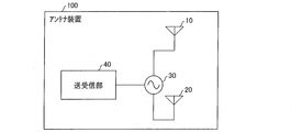
- FIG. 1 is a functional block diagram showing a schematic configuration of an antenna device 100 according to one embodiment (first embodiment) of the present invention.
- 2 is a side sectional view showing a schematic configuration of the antenna device 100.
- FIG. 2A shows a state where the finger 1 is not touching a predetermined position on the antenna device 100, and FIG. The state where the finger 1 is touching the predetermined position is shown.
- the antenna device 100 stores an antenna element 10, a contact pad (human antenna element) 20, a power feeding unit 30, a transmission / reception unit (wireless means) 40, and these members.
- a housing 60 is provided.
- the antenna element 10 may be an antenna element for transmitting and receiving wireless communication, and the structure is not particularly limited.
- the antenna element 10 has an electrical length D corresponding to the used frequency band.
- the antenna element 10 may be provided with a matching circuit for matching the impedance of the antenna element 10 between the antenna element 10 and the power feeding unit 30.
- the contact pad 20 is a conductive piece that is electrically connected or capacitively coupled to the human body and receives a radio signal via the human body.
- the contact pad 20 is arranged on the outer edge of the housing 60, and the finger 1 and the contact pad 20 are configured to be capacitively coupled.
- the invention is not limited to this, and the contact pad 20 may be exposed on the surface of the housing 60 and the finger 1 and the contact pad 20 may be electrically connected.
- the contact pad 20 may be in contact with or close to the contact pad 20 as long as it is a part of the human body, and is not limited to the finger 1.
- the contact pad 20 has an electrical length L.
- the human body is floating with respect to the ground (GND) of the antenna device 100 while a current flows with a certain amount of loss. Due to such characteristics of the human body, the human body antenna can be suitably used to receive a radio signal.
- the human body antenna has an advantageous effect of having characteristics in a wide frequency band.
- the antenna device 100 can form such a human body antenna when the finger 1 comes close to the contact pad 20.
- the antenna element 10 and the contact pad 20 can be configured to be used in the same communication system.
- the transmission / reception unit 40 is a circuit board including a wireless circuit that simultaneously supplies power to both the antenna element 10 and the contact pad 20 to realize wireless communication.
- the transmission / reception unit 40 is connected to the power supply unit 30, and both the antenna element 10 and the contact pad 20 are supplied with power from the power supply unit 30.
- the transmitting / receiving unit 40 when the finger 1 is not touching a predetermined position on the antenna device 100 (position close to the contact pad 20 and capacitively coupled), the transmitting / receiving unit 40 In addition, a radio signal can be received using a signal from the antenna element 10.
- the transmitting / receiving unit 40 mainly uses the signal of the human body antenna including the contact pad 20. A radio signal can be received.
- the predetermined position is not limited to one point, and can be within a certain range.
- a position corresponding to the plate surface can be set as the predetermined position.
- the antenna device 100 supplies power to both the antenna element 10 and the contact pad 20 simultaneously.
- the antenna element 10 and the contact pad 20 can be used in the same communication system, when the human body (for example, the finger 1) is in contact with or close to the antenna device 100, the human body antenna can be used successfully. it can. Further, even when the human body is not in contact with or close to the antenna device 100, a radio signal can be suitably received via the antenna element 10. And according to this embodiment, the switching mechanism and control like the technique of patent document 2 are unnecessary, and suitable reception of a radio signal is realizable with a simple structure.
- the antenna 10 and the contact pad 20 are used in the same communication system. Therefore, two antenna signals, that is, a signal transmitted / received by the antenna element 10 and a signal transmitted / received by the contact pad 20 are input / output to / from the transmitting / receiving unit 40. Therefore, in one aspect, the transmission / reception unit 40 can also perform diversity reception and / or transmission based on the two antenna signals. In another aspect, the transmission / reception unit 40 can also receive and / or transmit MIMO (Multi (Input Multi Output) or the like based on the two antenna signals.
- MIMO Multi (Input Multi Output)
- the contact pad 20 in the state shown in FIG. 2A (a state where the human body antenna is not used), the contact pad 20 is supplied with power from the power supply unit 30 even though it is not particularly used. At this time, the contact pad 20 and the antenna element 10 may interfere with each other, and the characteristics of the antenna element 10 may deteriorate. Therefore, it is preferable that unnecessary mutual interference between the contact pad 20 and the antenna element 10 is suppressed in the state shown in FIG.
- the electrical length L of the contact pad 20 is shorter than the electrical length D of the antenna element 10.
- the electrical length D of the antenna element 10 refers to the electrical length from the power feeding unit 30 to the tip of the antenna element 10
- the electrical length L of the contact pad 20 refers to the electrical length from the power feeding unit 30 to the tip of the contact pad 20. Point to the length.
- the antenna element 10 is configured as a 1 / 4 ⁇ antenna (for example, a monopole antenna) (when the wavelength of the used frequency band of the antenna element 10 is ⁇ , the electrical length D is 1 / 4 ⁇ or approximately 1 / 4 ⁇ (specifically, 1 / 8 ⁇ or more and 3 / 8 ⁇ or less), generally 1 / 8 ⁇ or approximately 1 / 8 ⁇ (specifically 1 / 16 ⁇ ) with respect to such an antenna element 10.
- An antenna having an electrical length of 3 / 16 ⁇ or less has almost no effect.
- the contact pad 20 and the antenna element 10 are reduced. Unnecessary mutual interference between the two can be more suitably reduced.
- substantially 1 ⁇ 4 wavelength and “substantially 1 ⁇ 4 ⁇ ” refer to a range from 1/8 to 3/8 of one wavelength, and in particular, a case where the wavelength is exactly 1 ⁇ 4. preferable.
- approximately 1/8 wavelength and “approximately 1 / 8 ⁇ ” refer to a range of 1/16 to 3/16 of one wavelength, and it is particularly preferable that the wavelength is exactly 1/8.
- the electrical length of the human body antenna including the contact pad 20 is longer than the electrical length L of the contact pad 20. Therefore, it is preferable to make the electrical length L of the contact pad 20 shorter than the electrical length corresponding to the used frequency band (the electrical length D of the antenna element 10). Thereby, the operation
- the contact pad 20 by configuring the contact pad 20 to be short, the mounting area in the antenna device 100 can be reduced, and the antenna device 100 can be made compact.
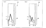
- the shape, arrangement, and the like of the antenna element 10 and the contact pad 20 are not particularly limited, but in one embodiment, the antenna element 10 and the contact pad 20 are configured to be capacitively coupled as shown in FIG. It is preferable.
- the tip of the antenna element 10 and the tip of the contact pad 20 may be capacitively coupled at the position indicated by C in the figure.
- the antenna element 10 is couple
- the antenna element 10 has an adverse effect on the human body antenna because the antenna element 10 and the contact pad 20 appear to be equivalent to one element having a shorter electrical length. Can be suitably suppressed.
- a part of the antenna element 10 and a part of the contact pad 20 may be capacitively coupled.
- the antenna element 10 is coupled to the contact pad 20, and the antenna element 10 can be used as a part of the human body antenna.
- the antenna element 10 and the contact pad 20 appear to be equivalent to the presence of one element having a shorter electrical length. It can suppress suitably that 10 has a bad influence on a human body antenna.
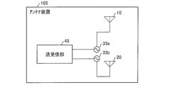
- FIG. 4 is a functional block diagram showing a schematic configuration of the antenna device 103 according to one embodiment (second embodiment) of the present invention.
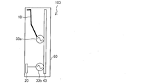
- FIG. 5 is a side sectional view showing a schematic configuration of the antenna device 103.
- the same member number is attached
- the antenna device 103 includes an antenna element 10, a contact pad (human body antenna element) 20, a power feeding unit 33 a, a power feeding unit 33 b, a transmission / reception unit (wireless means) 43, and a housing 60.
- the transmission / reception unit 43 supplies power to the antenna element 10 and the contact pad 20 from different power supply units (33a and 33b). This is different from the first embodiment.
- the antenna element 10 and the contact pad 20 may be supplied with power from different power supply units. Even in such a configuration, the antenna device 103 supplies power to both the antenna element 10 and the contact pad 20 at the same time, so that the human body (for example, the finger 1) is in contact with or close to the antenna device 103. In some cases, the human body antenna can be used successfully, and even when the human body is not in contact with or close to the antenna device 103, the radio signal can be suitably received via the antenna element 10.
- the power feeding unit 33a and the power feeding unit 33b may be arranged at positions separated from each other.
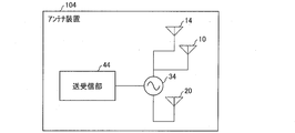
- FIG. 6 is a functional block diagram showing a schematic configuration of the antenna device 104 according to one embodiment (third embodiment) of the present invention.
- FIG. 7 is a side sectional view showing a schematic configuration of the antenna device 104.
- the same member number is attached
- the antenna device 104 includes an antenna element 10, an antenna element 14, a contact pad 20, a power feeding unit 34, a transmission / reception unit (wireless means) 44, and a housing 60.
- the transmission / reception unit 44 supplies power to the plurality of antenna elements (10 and 14) and the contact pad 20 from the power supply unit 34. This is different from the first embodiment.
- the antenna element 14 can be a member substantially similar to the antenna element 10 of the first embodiment.
- the antenna device 104 includes a plurality of antenna elements, and can assign different frequency bands to the respective antenna elements.
- the human body antenna can cope with a wide frequency band.
- the antenna apparatus 104 can cope with a plurality of frequency bands (multiband) successfully.
- the antenna device 104 supplies power to the antenna element 10, the antenna element 14, and the contact pad 20 at the same time, so that the human body (for example, the finger 1) is in contact with or close to the antenna device 104.
- the human body antenna can be used successfully, and a radio signal can be suitably received via the antenna element 10 and the antenna element 14 even when the human body is not in contact with or close to the antenna device 104.
- the electrical length L of the contact pad 20 is shorter than the electrical length of the antenna element, as in the first embodiment.
- the electrical length of the antenna element 10 is D1 and the electrical length of the antenna element 14 is D2, the electrical length L is shorter than the electrical length D1 and is longer than the electrical length D2. Short is preferred.
- the antenna element 10 and the antenna element 14 are configured as 1 / 4 ⁇ antennas (for example, monopole antennas) (the wavelength of the used frequency band of the antenna element 10 is ⁇ 1, and the used frequency of the antenna element 14 is When the wavelength of the band is ⁇ 2, the electrical length D1 is 1 / 4 ⁇ 1 or approximately 1 / 4 ⁇ 1 (specifically, 1 / 8 ⁇ 1 to 3 / 8 ⁇ 1), and the electrical length D2 is 1 / 4 ⁇ 2 or approximately 1 / 4 ⁇ 2.
- the electrical length L is 1/8 wavelength or approximately 1/8 wavelength (specifically, 1/16 wavelength or more and 3/16 wavelength or less) or less (1 / 8 ⁇ 1 or approximately 1 / 8 ⁇ 1 (specifically) of the used frequency band.
- the electrical length of the human body antenna including the contact pad 20 is longer than the electrical length L of the contact pad 20.
- the electrical length L of the contact pad 20 be shorter than the electrical length corresponding to the frequency band used (the electrical length D1 of the antenna element 10 and the electrical length D2 of the antenna element 14).
- the contact pad 20 by configuring the contact pad 20 to be short, the mounting area in the antenna device 104 can be reduced.
- the antenna device 104 may include three or more antenna elements. Even if it is a case where it comprises in this way, there can exist the same effect.
- antenna device When the antenna device (antenna devices 100 to 104) according to one embodiment of the present invention is electrically connected or capacitively coupled to an antenna element (antenna elements 10 to 12 and 14) that receives radio signals and a human body, A human body antenna element (contact pad 20) for receiving a radio signal via the human body, and wireless means (transmission / reception units 40, 43, 44) for simultaneously feeding the antenna element and the human body antenna element. Yes.
- the antenna device feeds power to both the antenna element and the human body antenna element. Therefore, when the human body is in contact with or close to the human body, the human body antenna can be used successfully. Further, even when the human body is not in contact with or in close proximity, a radio signal can be suitably received via the antenna element.
- the switching mechanism and control as in the technique of Patent Document 2 are not required, and the invention can be realized with a simple configuration.
- a radio signal can be suitably received even when the human body antenna is not used, with a simple configuration.
- the electrical length of the human body antenna element is greater than the electrical length of the antenna element (antenna elements 10 to 12, 14). Is preferably short.
- the electrical length of the human body antenna becomes longer than the electrical length of the human body antenna element. Therefore, the electrical length of the human body antenna element itself is preferably shorter than the electrical length of the antenna element corresponding to the used frequency band. Thereby, when a human body contacts or approaches, the operation of the human body antenna in the used frequency band can be improved.
- the human body antenna element by configuring the human body antenna element to be short, the mounting area can be reduced, and a more compact antenna device can be provided.
- the electrical length of the antenna element is 1 ⁇ 4 wavelength of the frequency band used by the antenna element or about 1 / 4 wavelength (specifically, 1/8 wavelength or more and 3/8 wavelength or less), and the electrical length of the human body antenna element (contact pad 20) is 1/8 wavelength of the use frequency band of the antenna element or substantially It is preferable that the wavelength is 1/8 wavelength (specifically, 1/16 wavelength or more and 3/16 wavelength or less).
- an antenna having an electrical length of 1 ⁇ 4 wavelength or approximately 1 ⁇ 4 wavelength (specifically, 8 wavelength or more and ⁇ wavelength or less) of the used frequency band 8 wavelength or 1 /
- An antenna having an electrical length of a wavelength (specifically, 1/16 wavelength or more and 3/16 wavelength or less) has little effect. Therefore, according to said structure, the mutual interference between a human body antenna element and an antenna element when a human body is not contacting or adjoining can be reduced more. Therefore, it is possible to more suitably suppress the elements from adversely affecting each other due to feeding power to both the antenna element and the human body antenna element.
- the antenna element (antenna elements 11 and 12) and the human body antenna element (contact pad 20) are capacitively coupled. May be.
- the antenna element when the human body is in contact with or close to the human body antenna element, the antenna element is connected to the human body via the human body antenna element, so that the antenna element can also be used as a part of the human body antenna. . Accordingly, the antenna element can be effectively used not only when the human body does not contact or approach the human body antenna element but also when the human body contacts or approaches the human body antenna element.
- the human body antenna element and the antenna element appear to be one, so that the antenna element can be prevented from adversely affecting the human body antenna.
- An antenna device (antenna device 101) according to one embodiment of the present invention has a capacitive coupling between the tip of the antenna element (antenna element 11) and the tip of the human body antenna element (contact pad 20). It may be.
- the entire antenna element can be used as a part of the human body antenna. Also, when the human body is in contact with or close to the human body antenna element, the human body antenna element and the antenna element appear to be equivalent to one element having a shorter electrical length. It is possible to more appropriately suppress adverse effects.
- the antenna device (antenna device 104) according to one embodiment of the present invention may include a plurality of the antenna elements.
- the human body antenna can support a wide frequency band.
- the antenna device since the antenna device includes a plurality of antenna elements, it can cope with a plurality of frequency bands (multiband). Therefore, according to the above configuration, the antenna device can cope with a plurality of frequency bands successfully.
- the present invention can be suitably used in the field of manufacturing wireless communication devices.
Landscapes
- Engineering & Computer Science (AREA)
- Computer Networks & Wireless Communication (AREA)
- Support Of Aerials (AREA)
- Details Of Aerials (AREA)
Abstract
アンテナ装置(100)は、アンテナ素子(10)と、接触パッド(20)と、アンテナ素子(10)および接触パッド(20)を同時に給電する送受信部(40)と、を備えている。
Description
本発明は、アンテナ装置に関するものであり、特に、人体をアンテナとして利用するアンテナ装置に関するものである。
近年、人体を介して無線信号を送受信する技術(以降、「人体アンテナ」とも称する)を利用したアンテナ装置が開発されている。
例えば、特許文献1には、誘電体筐体と、前記誘電体筐体内部に設置され放射素子として動作する導体板と、前記誘電体筐体の側面に沿って設けられた導体片と、前記導体板と前記導体片との間に高周波電圧を印加する高周波電源とを備えた無線端末用アンテナ装置が記載されている。
上記構成の無線端末用アンテナ装置を使用するときに、使用者は、誘電体筐体の側面を手で把持することとなる。使用者の手によって誘電体筐体が把持された際に、誘電体筐体の側面に貼付された導体片と使用者の手(すなわち人体)とが接触することで、無線端末用アンテナ装置は、アンテナとして動作する。つまり、導体片と人体とが接触することにより、人体が地導体、導体板が放射素子として動作するモノポールアンテナが形成され、導体板上の電流から電波が放射される。
但し、特許文献1に記載の無線端末用アンテナ装置では、使用者が誘電体筐体の側面を手で把持していないときは、上記モノポールアンテナは形成されず、アンテナ装置は無線通信を首尾よく行うことができない。
これに対し、特許文献2に、図8に示すような携帯用無線通信装置2が記載されている。携帯用無線通信装置2は、アンテナ4、人体3に接触する導電性端子5、アンテナ4に給電する給電部6a、導電性端子5に給電する給電部6b、切り替え手段7および送受信機8を備えている。送受信機8は、切り替え手段7によって、アンテナ4または導電性端子5の何れかに接続し、給電するようになっている。
携帯用無線通信装置2は、アンテナ4と、人体アンテナを構成する導電性端子5との両方を備え、受信状態に応じて何れかに送受信機8が接続するように切り替えることにより、人体アンテナを利用できないときでも、アンテナ4による無線通信を行うことができる。
しかし、特許文献2に記載の携帯用無線通信装置2では、送受信機8の給電先を切り替える機構および制御が必要となり、装置の構成が複雑となる。人体アンテナを利用したアンテナ装置において、人体が接触または近接していないときでも無線信号を好適に受信することを簡易な構成で実現することができれば非常に有用である。
本発明は、上記の課題に鑑みてなされたものであり、人体アンテナを利用可能なアンテナ装置において、簡易な構成によって、人体アンテナを利用しないときでも無線信号を好適に受信するための技術を提供することを主たる目的とする。
本発明に係るアンテナ装置は、上記課題を解決するために、無線信号を受信するアンテナ素子と、人体と電気的に接続または容量性結合したときに、該人体を介して無線信号を受信するための人体アンテナ素子と、該アンテナ素子および該人体アンテナ素子を同時に給電する無線手段と、を備えていることを特徴としている。
本発明によれば、人体アンテナを利用可能なアンテナ装置において、簡易な構成によって、人体アンテナを利用しないときでも無線信号を好適に受信することができる。
〔第1実施形態〕
図1は、本発明の一実施形態(第1実施形態)に係るアンテナ装置100の概略構成を示す機能ブロック図である。また、図2は、アンテナ装置100の概略構成を示す側方断面図であり、(a)はアンテナ装置100上の所定位置に指1が触れていない状態を示し、(b)はアンテナ装置100上の所定位置に指1が触れている状態を示す。
図1は、本発明の一実施形態(第1実施形態)に係るアンテナ装置100の概略構成を示す機能ブロック図である。また、図2は、アンテナ装置100の概略構成を示す側方断面図であり、(a)はアンテナ装置100上の所定位置に指1が触れていない状態を示し、(b)はアンテナ装置100上の所定位置に指1が触れている状態を示す。
図1および図2に示すように、アンテナ装置100は、アンテナ素子10、接触パッド(人体アンテナ素子)20、給電部30、送受信部(無線手段)40、および、これらの部材を格納するための筐体60を備えている。
アンテナ素子10は、無線通信を送受信するためのアンテナ素子であればよく、特に構造は限定されない。本実施形態において、アンテナ素子10は、使用周波数帯に応じた電気長Dを有している。なお、アンテナ素子10は、給電部30との間に、アンテナ素子10のインピーダンスを整合させるための整合回路を備えていてもよい。
接触パッド20は、人体と電気的に接続または容量性結合し、当該人体を介して無線信号を受信する導電片である。本実施形態では、図2の(b)に示すように、接触パッド20が筐体60の外縁に配置され、指1と接触パッド20とが容量性結合するように構成されているが、本発明はこれに限定されず、接触パッド20が筐体60の表面に露出し、指1と接触パッド20とが電気的に接続するように構成されていてもよい。また、接触パッド20に接触または近接するのは、人体の一部であればよく、指1に限定されない。本実施形態において、接触パッド20は、電気長Lを有している。
なお、人体は、ある程度の損失を伴って電流が流れるとともに、アンテナ装置100のGND(アース)に対して浮遊している。人体のこのような特性により、人体アンテナは、無線信号を受信するために好適に用いることができる。人体アンテナは、特に、幅広い周波数帯域に特性を有しているという有利な効果を有している。アンテナ装置100は、接触パッド20に指1が近接したときに、このような人体アンテナを構成することができる。
なお、典型的には、アンテナ素子10と接触パッド20とが同一の通信システムで使用されるように構成することができる。
送受信部40は、アンテナ素子10および接触パッド20の両方に同時に給電して無線通信を実現する無線回路を備えた回路基板である。送受信部40は給電部30に接続しており、アンテナ素子10および接触パッド20は何れも、給電部30から給電されている。
ここで、図2の(a)に示すように、指1がアンテナ装置100上の所定位置(接触パッド20に近接し、容量性結合する位置)に触れていないとき、送受信部40は、主に、アンテナ素子10からの信号を利用して無線信号を受信することができる。
一方、図2の(b)に示すように、指1が上記所定位置に触れているとき、送受信部40は、主に、接触パッド20を含んで構成される人体アンテナの信号を利用して無線信号を受信することができる。
なお、筐体60上には、上記所定位置をユーザが容易に把握し得るように、印刷または装飾を施しておくことが好ましい。また、上記所定位置は、一点に限定されるものではなく、一定の範囲内とすることができる。例えば、接触パッド20を板状に形成した場合に、当該板面に対応する位置を上記所定位置とすることができる。
このように、本実施形態によれば、アンテナ装置100は、アンテナ素子10と接触パッド20との両方に同時に給電するようになっている。ここで、アンテナ素子10と接触パッド20とは同一の通信システムで利用され得るため、人体(例えば、指1)がアンテナ装置100に接触または近接したときは、人体アンテナを首尾よく利用することができる。また、人体がアンテナ装置100に接触または近接していないときでもアンテナ素子10を介して無線信号を好適に受信することができる。そして、本実施形態によれば、特許文献2の技術のような切り替え機構および制御が必要なく、簡易な構成で無線信号の好適な受信を実現することができる。
また、本実施形態に係るアンテナ装置100では、アンテナ10および接触パッド20が同一の通信システムにおいて利用される。そのため、送受信部40には、2つアンテナ信号、すなわち、アンテナ素子10で送受信した信号、および接触パッド20で送受信した信号が入出力される。そのため、一つの局面において、送受信部40は、上記2つのアンテナ信号に基づいて、ダイバーシチ受信および/または送信を行うことも可能である。また、他の局面において、送受信部40は、上記2つのアンテナ信号に基づいて、MIMO(Multi Input Multi Output)等の受信および/または送信を行うことも可能である。
なお、本実施形態では、図2の(a)に示す状態(人体アンテナを利用しない状態)において、接触パッド20は特に利用されないにもかかわらず、給電部30から給電されている。このとき、接触パッド20とアンテナ素子10とが相互干渉して、アンテナ素子10の特性が劣化するおそれがある。それゆえ、図2の(a)に示す状態において、接触パッド20とアンテナ素子10との間の不要な相互干渉を抑制するようになっていることが好ましい。
そのため、アンテナ素子10の電気長Dよりも、接触パッド20の電気長Lの方が短いことが好ましい。なお、アンテナ素子10の電気長Dとは、給電部30からアンテナ素子10の先端までの電気長を指し、接触パッド20の電気長Lとは、給電部30から接触パッド20の先端までの電気長を指す。
これにより、接触パッド20とアンテナ素子10との間の不要な相互干渉を低減することができる。特に、アンテナ素子10を1/4λ系のアンテナ(例えば、モノポールアンテナ)として構成している場合(アンテナ素子10の使用周波数帯の波長をλとしたとき、電気長Dが1/4λまたは略1/4λ(具体的には1/8λ以上3/8λ以下)である場合)、一般に、このようなアンテナ素子10に対して、1/8λまたは略1/8λ(具体的には1/16λ以上3/16λ以下)以下の電気長のアンテナは影響を殆ど及ぼさない。それゆえ、電気長Lを使用周波数帯の1/8波長または略1/8波長(具体的には1/16波長以上3/16波長以下)以下とすることにより、接触パッド20とアンテナ素子10との間の不要な相互干渉をより好適に低減することができる。
なお、本明細書において「略1/4波長」「略1/4λ」とは、一波長の1/8以上3/8以下の範囲を指し、一波長の丁度1/4となる場合が特に好ましい。また、「略1/8波長」「略1/8λ」とは、一波長の1/16以上3/16以下の範囲を指し、一波長の丁度1/8となる場合が特に好ましい。
また、接触パッド20を含んで構成される人体アンテナの電気的な長さは、接触パッド20の電気長Lよりも長くなる。そのため、使用周波数帯に対応する電気長(アンテナ素子10の電気長D)よりも、接触パッド20の電気長Lを短くしておくことが好ましい。これにより、使用周波数帯域における人体アンテナの動作を良好にすることができる。
また、接触パッド20を短く構成することにより、アンテナ装置100内における実装面積を低減することができ、アンテナ装置100をコンパクト化することができる。
また、アンテナ素子10および接触パッド20の形状、配置等は特に限定されないが、一実施形態において、図3に示すように、アンテナ素子10と接触パッド20とが、容量性結合するように構成されていることが好ましい。
例えば、図3の(a)に示すように、アンテナ素子10の先端部と、接触パッド20の先端部とが、図中Cに示す位置において容量性結合していてもよい。これにより、接触パッド20にアンテナ素子10が結合され、アンテナ素子10の全体を人体アンテナの一部として利用することができる。また、このとき、送受信部40から見ると、アンテナ素子10および接触パッド20のうち電気長が短い方の素子が一つ存在しているのと同等に見えるため、アンテナ素子10が人体アンテナに悪影響を及ぼすことを好適に抑制することができる。
また、図3の(b)に示すように、アンテナ素子10の一部と接触パッド20の一部とが、容量性結合していてもよい。この構成においても、接触パッド20にアンテナ素子10が結合され、アンテナ素子10を人体アンテナの一部として利用することができる。また、図3(a)と同様に、送受信部40から見ると、アンテナ素子10および接触パッド20のうち電気長が短い方の素子が一つ存在しているのと同等に見えるため、アンテナ素子10が人体アンテナに悪影響を及ぼすことを好適に抑制することができる。
〔第2実施形態〕
図4は、本発明の一実施形態(第2実施形態)に係るアンテナ装置103の概略構成を示す機能ブロック図である。また、図5は、アンテナ装置103の概略構成を示す側方断面図である。なお、第1実施形態と同様の部材には同一の部材番号を付し、説明を省略する。
図4は、本発明の一実施形態(第2実施形態)に係るアンテナ装置103の概略構成を示す機能ブロック図である。また、図5は、アンテナ装置103の概略構成を示す側方断面図である。なお、第1実施形態と同様の部材には同一の部材番号を付し、説明を省略する。
図4および図5に示すように、アンテナ装置103は、アンテナ素子10、接触パッド(人体アンテナ素子)20、給電部33a、給電部33b、送受信部(無線手段)43および筐体60を備えている。そして、本実施形態において、送受信部43は、アンテナ素子10および接触パッド20に対して、それぞれ異なる給電部(33aおよび33b)から給電している。この点において、第1実施形態と異なっている。
このように、本発明では、アンテナ素子10および接触パッド20に対して、異なる給電部から給電するようになっていてもよい。このような形態においても、アンテナ装置103が、アンテナ素子10と接触パッド20との両方に同時に給電するようになっていることにより、人体(例えば、指1)がアンテナ装置103に接触または近接したときは、人体アンテナを首尾よく利用することができ、人体がアンテナ装置103に接触または近接していないときでもアンテナ素子10を介して無線信号を好適に受信することができる。
また、図5に示すように、給電部33aと給電部33bとは離れた位置に配置されていてもよい。
〔第3実施形態〕
図6は、本発明の一実施形態(第3実施形態)に係るアンテナ装置104の概略構成を示す機能ブロック図である。また、図7は、アンテナ装置104の概略構成を示す側方断面図である。なお、第1実施形態と同様の部材には同一の部材番号を付し、説明を省略する。
図6は、本発明の一実施形態(第3実施形態)に係るアンテナ装置104の概略構成を示す機能ブロック図である。また、図7は、アンテナ装置104の概略構成を示す側方断面図である。なお、第1実施形態と同様の部材には同一の部材番号を付し、説明を省略する。
図6および図7に示すように、アンテナ装置104は、アンテナ素子10、アンテナ素子14、接触パッド20、給電部34、送受信部(無線手段)44および筐体60を備えている。そして、本実施形態において、送受信部44は、複数のアンテナ素子(10および14)および接触パッド20に対して、給電部34から給電している。この点において、第1実施形態と異なっている。なお、アンテナ素子14は、実施形態1のアンテナ素子10とほぼ同様の部材とすることができる。
このように、アンテナ装置104は、アンテナ素子を複数備えており、それぞれのアンテナ素子に対して異なる周波数帯域を割り当てることができる。また、一般に、人体アンテナは、幅広い周波数帯域に対応可能である。これにより、アンテナ装置104は、複数の周波数帯域(マルチバンド)に首尾よく対応することができる。
このような形態においても、アンテナ装置104が、アンテナ素子10、アンテナ素子14および接触パッド20に同時に給電するようになっていることにより、人体(例えば、指1)がアンテナ装置104に接触または近接したときは、人体アンテナを首尾よく利用することができ、人体がアンテナ装置104に接触または近接していないときでもアンテナ素子10およびアンテナ素子14を介して無線信号を好適に受信することができる。
なお、本実施形態において、第1実施形態と同様に、接触パッド20の電気長Lを、アンテナ素子の電気長よりも短くすることが好ましい。
すなわち、図7に示すように、アンテナ素子10の電気長をD1とし、アンテナ素子14の電気長をD2としたとき、電気長Lは、電気長D1よりも短く、かつ、電気長D2よりも短いことが好ましい。これにより、アンテナ素子10およびアンテナ素子14を1/4λ系のアンテナ(例えば、モノポールアンテナ)として構成している場合(アンテナ素子10の使用周波数帯の波長をλ1とし、アンテナ素子14の使用周波数帯の波長をλ2としたとき、電気長D1が1/4λ1または略1/4λ1(具体的には1/8λ1以上3/8λ1以下)であり、電気長D2が1/4λ2または略1/4λ2(具体的には1/8λ2以上3/8λ2以下)である場合)、一般に、このようなアンテナ素子10およびアンテナ素子14に対して、それぞれの使用周波数帯の1/8波長または略1/8波長(具体的には1/16波長以上3/16波長以下)以下の電気長のアンテナは影響を殆ど及ぼさない。それゆえ、電気長Lを使用周波数帯の1/8波長または略1/8波長(具体的には1/16波長以上3/16波長以下)以下(1/8λ1または略1/8λ1(具体的には1/16λ1以上3/16λ1以下)以下、かつ、1/8λ2または略1/8λ2(具体的には1/16λ2以上3/16λ2以下)以下)とすることにより、接触パッド20とアンテナ素子10およびアンテナ素子14との間の不要な相互干渉をより好適に低減することができる。
また、第1実施形態と同様に、接触パッド20を含んで構成される人体アンテナの電気的な長さは、接触パッド20の電気長Lよりも長くなる。そのため、使用周波数帯に対応する電気長(アンテナ素子10の電気長D1およびアンテナ素子14の電気長D2)よりも、接触パッド20の電気長Lを短くしておくことが好ましい。これにより、使用周波数帯域における人体アンテナの動作を良好にすることができる。
また、接触パッド20を短く構成することにより、アンテナ装置104内における実装面積を低減することができる。
なお、アンテナ装置104は、3本以上のアンテナ素子を備えていてもよい。このように構成した場合であっても、同様の効果を奏することができる。
(まとめ)
本発明の一態様に係るアンテナ装置(アンテナ装置100~104)は、無線信号を受信するアンテナ素子(アンテナ素子10~12、14)と、人体と電気的に接続または容量性結合したときに、該人体を介して無線信号を受信するための人体アンテナ素子(接触パッド20)と、該アンテナ素子および該人体アンテナ素子を同時に給電する無線手段(送受信部40、43、44)と、を備えている。
本発明の一態様に係るアンテナ装置(アンテナ装置100~104)は、無線信号を受信するアンテナ素子(アンテナ素子10~12、14)と、人体と電気的に接続または容量性結合したときに、該人体を介して無線信号を受信するための人体アンテナ素子(接触パッド20)と、該アンテナ素子および該人体アンテナ素子を同時に給電する無線手段(送受信部40、43、44)と、を備えている。
上記の構成によれば、アンテナ装置は、アンテナ素子と人体アンテナ素子との両方に給電するようになっている。そのため、人体が接触または近接したときは、人体アンテナを首尾よく利用することができる。また、人体が接触または近接していないときでもアンテナ素子を介して無線信号を好適に受信することができる。その上、特許文献2の技術のような切り替え機構および制御が必要なく、簡易な構成で発明を実現することができる。
以上のように、上記の構成によれば、人体アンテナを利用可能なアンテナ装置において、簡易な構成によって、人体アンテナを利用しないときでも無線信号を好適に受信することができる。
本発明の一態様に係るアンテナ装置(アンテナ装置100~104)では、上記アンテナ素子(アンテナ素子10~12、14)の電気長よりも、上記人体アンテナ素子(接触パッド20)の電気長の方が短いことが好ましい。
上記の構成によれば、人体が接触または近接していないときにおける、人体アンテナ素子とアンテナ素子との間の相互干渉を低減することができる。これにより、アンテナ素子と人体アンテナ素子との両方に給電することに起因して素子同士が互いに悪影響を及ぼすことを好適に抑制することができる。
また、人体アンテナ素子に人体が接触または近接すると、人体アンテナの電気的な長さは、人体アンテナ素子の電気長よりも長くなる。そのため、人体アンテナ素子そのものの電気長は、使用周波数帯に対応するアンテナ素子の電気長よりも短くしておくことが好ましい。これにより、人体が接触または近接したときに使用周波数帯域における人体アンテナの動作を良好にすることができる。
また、人体アンテナ素子を短く構成することにより、実装面積を低減することができ、よりコンパクトなアンテナ装置を提供することが可能となる。
本発明の一態様に係るアンテナ装置(アンテナ装置100~104)では、上記アンテナ素子(アンテナ素子10~12、14)の電気長が、当該アンテナ素子の使用周波数帯の1/4波長または略1/4波長(具体的には1/8波長以上3/8波長以下)であり、上記人体アンテナ素子(接触パッド20)の電気長が、上記アンテナ素子の使用周波数帯の1/8波長または略1/8波長(具体的には1/16波長以上3/16波長以下)以下であることが好ましい。
一般に、使用周波数帯の1/4波長または略1/4波長(具体的には1/8波長以上3/8波長以下)の電気長のアンテナに対して、1/8波長または略1/8波長(具体的には1/16波長以上3/16波長以下)以下の電気長のアンテナは影響を殆ど及ぼさない。したがって、上記の構成によれば、人体が接触または近接していないときにおける、人体アンテナ素子とアンテナ素子との間の相互干渉をより低減することができる。よって、アンテナ素子と人体アンテナ素子との両方に給電することに起因して素子同士が互いに悪影響を及ぼすことをより好適に抑制することができる。
本発明の一態様に係るアンテナ装置(アンテナ装置101、102)は、上記アンテナ素子(アンテナ素子11、12)と上記人体アンテナ素子(接触パッド20)とが、容量性結合しているものであってもよい。
上記の構成によれば、人体アンテナ素子に人体が接触または近接したときに、アンテナ素子が人体アンテナ素子を介して人体に接続されるため、アンテナ素子も人体アンテナの一部として利用することができる。これにより、人体アンテナ素子に人体が接触または近接しないときだけではなく、人体アンテナ素子に人体が接触または近接したときにも、アンテナ素子を有効利用することができる。
また、人体アンテナ素子に人体が接触または近接したときに、人体アンテナ素子およびアンテナ素子が一つに見えるため、アンテナ素子が、人体アンテナに悪影響を及ぼすことを抑制することができる。
本発明の一態様に係るアンテナ装置(アンテナ装置101)は、上記アンテナ素子(アンテナ素子11)の先端部と、上記人体アンテナ素子(接触パッド20)の先端部とが容量性結合しているものであってもよい。
上記の構成によれば、人体アンテナ素子に人体が接触または近接したときに、アンテナ素子の全体を人体アンテナの一部として利用することができる。また、人体アンテナ素子に人体が接触または近接したときに、人体アンテナ素子およびアンテナ素子のうち電気長が短い方の素子が一つ存在しているのと同等に見えるため、アンテナ素子が人体アンテナに悪影響を及ぼすことをより好適に抑制することができる。
本発明の一態様に係るアンテナ装置(アンテナ装置104)は、上記アンテナ素子を複数備えているものであってもよい。
一般に、人体アンテナは幅広い周波数帯域に対応可能である。また、アンテナ装置が複数のアンテナ素子を備えることにより、複数の周波数帯域(マルチバンド)に対応することができる。従って、上記の構成によれば、アンテナ装置は複数の周波数帯域に首尾よく対応することができる。
なお、本発明は上述した実施形態に限定されるものではなく、請求項に示した範囲で種々の変更が可能であり、それぞれ開示された技術的手段を適宜組み合わせて得られる実施形態についても本発明の技術的範囲に含まれる。
本発明は、無線通信機器の製造分野において好適に利用可能である。
1 指
10、11、12、14 アンテナ素子
20 接触パッド(人体アンテナ素子)
30、33a、33b、34 給電部
40、43、44 送受信部(無線手段)
60 筐体
100、101、102、103、104 アンテナ装置
10、11、12、14 アンテナ素子
20 接触パッド(人体アンテナ素子)
30、33a、33b、34 給電部
40、43、44 送受信部(無線手段)
60 筐体
100、101、102、103、104 アンテナ装置
Claims (6)
- 無線信号を受信するアンテナ素子と、
人体と電気的に接続または容量性結合したときに、該人体を介して無線信号を受信するための人体アンテナ素子と、
該アンテナ素子および該人体アンテナ素子を同時に給電する無線手段と、を備えていることを特徴とするアンテナ装置。 - 上記アンテナ素子の電気長よりも、上記人体アンテナ素子の電気長の方が短いことを特徴とする請求項1に記載のアンテナ装置。
- 上記アンテナ素子の電気長が、当該アンテナ素子の使用周波数帯の1/8波長以上3/8波長以下であり、
上記人体アンテナ素子の電気長が、上記アンテナ素子の使用周波数帯の3/16波長以下であることを特徴とする請求項1または2に記載のアンテナ装置。 - 上記アンテナ素子と上記人体アンテナ素子とが、容量性結合していることを特徴とする請求項1~3の何れか1項に記載のアンテナ装置。
- 上記アンテナ素子の先端部と、上記人体アンテナ素子の先端部とが容量性結合していることを特徴とする請求項4に記載のアンテナ装置。
- 上記アンテナ素子を複数備えていることを特徴とする請求項1~5の何れか1項に記載のアンテナ装置。
Applications Claiming Priority (2)
| Application Number | Priority Date | Filing Date | Title |
|---|---|---|---|
| JP2011-267310 | 2011-12-06 | ||
| JP2011267310A JP2013121017A (ja) | 2011-12-06 | 2011-12-06 | アンテナ装置 |
Publications (1)
| Publication Number | Publication Date |
|---|---|
| WO2013084615A1 true WO2013084615A1 (ja) | 2013-06-13 |
Family
ID=48573998
Family Applications (1)
| Application Number | Title | Priority Date | Filing Date |
|---|---|---|---|
| PCT/JP2012/077645 Ceased WO2013084615A1 (ja) | 2011-12-06 | 2012-10-25 | アンテナ装置 |
Country Status (2)
| Country | Link |
|---|---|
| JP (1) | JP2013121017A (ja) |
| WO (1) | WO2013084615A1 (ja) |
Citations (2)
| Publication number | Priority date | Publication date | Assignee | Title |
|---|---|---|---|---|
| JPH10271060A (ja) * | 1997-03-24 | 1998-10-09 | Brother Ind Ltd | 携帯用無線通信装置 |
| JP2011211354A (ja) * | 2010-03-29 | 2011-10-20 | Kyocera Corp | 携帯通信端末 |
Family Cites Families (2)
| Publication number | Priority date | Publication date | Assignee | Title |
|---|---|---|---|---|
| JP3836004B2 (ja) * | 2000-09-11 | 2006-10-18 | 株式会社日本自動車部品総合研究所 | 携帯型無線機用アンテナ |
| KR100785764B1 (ko) * | 2005-05-11 | 2007-12-18 | 한국전자통신연구원 | 인체 안테나를 이용한 지상파 dmb 수신 장치 및 그 방법 |
-
2011
- 2011-12-06 JP JP2011267310A patent/JP2013121017A/ja active Pending
-
2012
- 2012-10-25 WO PCT/JP2012/077645 patent/WO2013084615A1/ja not_active Ceased
Patent Citations (2)
| Publication number | Priority date | Publication date | Assignee | Title |
|---|---|---|---|---|
| JPH10271060A (ja) * | 1997-03-24 | 1998-10-09 | Brother Ind Ltd | 携帯用無線通信装置 |
| JP2011211354A (ja) * | 2010-03-29 | 2011-10-20 | Kyocera Corp | 携帯通信端末 |
Also Published As
| Publication number | Publication date |
|---|---|
| JP2013121017A (ja) | 2013-06-17 |
Similar Documents
| Publication | Publication Date | Title |
|---|---|---|
| KR101689844B1 (ko) | 듀얼 피드 안테나 | |
| TWI483461B (zh) | 配置以用於低頻應用之天線 | |
| US7642966B2 (en) | Carrier and device | |
| JP6465109B2 (ja) | マルチアンテナ及びそれを備える無線装置 | |
| JP4297012B2 (ja) | アンテナ | |
| TW201238139A (en) | Handheld device | |
| US8648763B2 (en) | Ground radiator using capacitor | |
| JP5327322B2 (ja) | アンテナモジュール | |
| CN104037502B (zh) | 调频天线 | |
| JP2013507837A (ja) | 電子装置に設けられたアンテナ間に高度な分離を実現するアンテナシステム | |
| TW201210122A (en) | High isolation multiple port antenna array handheld mobile communication devices | |
| TW201249000A (en) | Antenna with multiple resonating conditions | |
| JP5061124B2 (ja) | アンテナ装置及び通信装置 | |
| WO2006062060A1 (ja) | 無線機用アンテナ装置及びそれを備えた携帯無線機 | |
| JP3828050B2 (ja) | アンテナアレー及び無線装置 | |
| CN101563811B (zh) | 天线布置 | |
| JP2004363848A (ja) | アンテナ実装基板及びそれを備えたpcカード | |
| JPWO2005069439A1 (ja) | マルチバンドアンテナ及び携帯型の通信機器 | |
| CN114079164A (zh) | 一种天线和电子设备 | |
| JP5422587B2 (ja) | アンテナ装置 | |
| CN108270068A (zh) | 具有全金属后壳的终端 | |
| WO2013084615A1 (ja) | アンテナ装置 | |
| JP2020065245A (ja) | スマートフォンケース | |
| CN102810736A (zh) | 天线及无线通讯装置 | |
| TWI583058B (zh) | 天線結構及具有該天線結構的無線通訊裝置 |
Legal Events
| Date | Code | Title | Description |
|---|---|---|---|
| 121 | Ep: the epo has been informed by wipo that ep was designated in this application |
Ref document number: 12855875 Country of ref document: EP Kind code of ref document: A1 |
|
| DPE1 | Request for preliminary examination filed after expiration of 19th month from priority date (pct application filed from 20040101) | ||
| NENP | Non-entry into the national phase |
Ref country code: DE |
|
| 122 | Ep: pct application non-entry in european phase |
Ref document number: 12855875 Country of ref document: EP Kind code of ref document: A1 |