WO2013077148A1 - 通信システムおよび通信装置 - Google Patents
通信システムおよび通信装置 Download PDFInfo
- Publication number
- WO2013077148A1 WO2013077148A1 PCT/JP2012/078004 JP2012078004W WO2013077148A1 WO 2013077148 A1 WO2013077148 A1 WO 2013077148A1 JP 2012078004 W JP2012078004 W JP 2012078004W WO 2013077148 A1 WO2013077148 A1 WO 2013077148A1
- Authority
- WO
- WIPO (PCT)
- Prior art keywords
- communication
- time
- time synchronization
- transmission
- processing
- Prior art date
- Legal status (The legal status is an assumption and is not a legal conclusion. Google has not performed a legal analysis and makes no representation as to the accuracy of the status listed.)
- Ceased
Links
Images


Classifications
-
- H—ELECTRICITY
- H04—ELECTRIC COMMUNICATION TECHNIQUE
- H04J—MULTIPLEX COMMUNICATION
- H04J3/00—Time-division multiplex systems
- H04J3/02—Details
- H04J3/06—Synchronising arrangements
- H04J3/0602—Systems characterised by the synchronising information used
- H04J3/0605—Special codes used as synchronising signal
-
- H—ELECTRICITY
- H04—ELECTRIC COMMUNICATION TECHNIQUE
- H04W—WIRELESS COMMUNICATION NETWORKS
- H04W28/00—Network traffic management; Network resource management
- H04W28/16—Central resource management; Negotiation of resources or communication parameters, e.g. negotiating bandwidth or QoS [Quality of Service]
- H04W28/18—Negotiating wireless communication parameters
-
- H—ELECTRICITY
- H04—ELECTRIC COMMUNICATION TECHNIQUE
- H04W—WIRELESS COMMUNICATION NETWORKS
- H04W56/00—Synchronisation arrangements
- H04W56/001—Synchronization between nodes
- H04W56/002—Mutual synchronization
Definitions
- the present invention relates to communication technology.
- Patent Document 1 describes a communication system that employs both wired communication and wireless communication.
- the communication devices constituting the system have both a wired communication function and a wired communication function.
- the communication device transmits a communication packet to which the same sequence number is assigned by both wired and wireless.
- the same circuit may be used even if the communication method is different, it is possible to share the same circuit.
- Such a configuration is referred to as a shared type. According to the shared type, the cost can be reduced by sharing the circuit.
- the shared circuit cannot be used simultaneously by multiple communication methods. For this reason, a method of using a shared circuit in a time division manner, in other words, a method of selecting a communication method in which the use of the shared circuit is permitted in a time division manner can be considered.
- a plurality of communication systems can be expressed as being multiplexed in time (or time division multiplexed).
- the present invention aims to provide various technologies useful for time division multiplexing of communication systems.
- time division multiplexing of the communication method can be adopted not only for the common type but also for the individual type. For this reason, this invention is not limited to any one of a shared type and an individual type.
- a communication system including a plurality of communication devices, each of the plurality of communication devices including a transmission / reception unit configured in accordance with a plurality of communication methods, and the plurality of communication devices.
- a communication processing unit that selects one of the communication methods according to a predetermined selection rule for each time slot based on the time in the apparatus, and performs communication via the transmission / reception unit according to the selected communication method,
- a plurality of communication devices include at least one first communication device that performs time synchronization master processing for including the time in the device itself as a time stamp in a time synchronization request signal and transmitting the time synchronization request signal; Receiving a time synchronization request signal and performing time synchronization slave processing for calibrating the time in the device of the device based on the time stamp in the time synchronization request signal; And a communication device, a communication system is provided.
- the time synchronization request signal includes a synchronization control portion and a signal body portion subsequent to the synchronization control portion
- the time in the apparatus at the transmission start timing of the signal body part is adopted as the time stamp
- the time in the apparatus at the reception start timing of the signal body part is A communication system is provided that calibrates with the received time stamp.
- the at least one first communication device is a plurality of first communication devices, and the time synchronization is performed.
- the master process includes a process of setting an authority level in the time synchronization request signal, and the time synchronization slave process is performed when the authority level of the received time synchronization request signal is equal to the time synchronization request signal received so far.
- a communication system is provided that is executed on condition that it is equal to or higher than the highest value of the authority level.
- a communication system according to any one of the first to third aspects, wherein the predetermined selection rule is a value within the apparatus when a communication method is selected.
- a communication system is provided that is a rule involving time of day.
- the at least one first communication device performs the time synchronization master process.
- a communication system is provided that includes at least one communication device capable of executing the time synchronization slave processing.
- the at least one second communication device performs the time synchronization slave processing.
- a communication system is provided that includes at least one communication device that can also execute the time synchronization master processing.
- a transmission / reception unit configured in accordance with a plurality of communication schemes, and a predetermined selection rule for each time slot based on the time in the apparatus, one of the plurality of communication schemes.
- a communication processing unit that performs communication via the transmission / reception unit according to the selected communication method, and the communication processing unit includes the time in the device itself as a time stamp in the time synchronization request signal.
- a communication device is provided that performs time synchronization master processing for transmitting the time synchronization request signal.
- the communication processing unit receives the time synchronization request signal and based on the time stamp in the time synchronization request signal.
- a communication device that further performs time synchronization slave processing for calibrating the in-device time of the device itself.
- a transmission / reception unit configured in conformity with a plurality of communication schemes and a predetermined selection rule for each time slot based on the time in the apparatus, one of the plurality of communication schemes.
- a communication processing unit that performs communication via the transmission / reception unit according to the selected communication method, the communication processing unit receiving the time synchronization request signal and the time stamp in the time synchronization request signal
- a communication device is provided that performs time-synchronized slave processing for calibrating the in-device time of the device.
- the first aspect it is possible to synchronize the time slot switching in each communication device among a plurality of communication devices. For this reason, it is possible to improve the reduction in communication efficiency caused by the time slot shifting between the plurality of communication devices.
- the time in the apparatus is acquired at the same position in the time synchronization request signal in the time synchronization master process and the time synchronization slave process. For this reason, synchronization accuracy can be increased.
- the transmission start timing of the signal body portion (in other words, the transition timing from the synchronization control portion to the signal body portion) exists at the initial transmission of the time synchronization request signal. For this reason, there is a time margin from the timing to the end of transmission of the time synchronization request signal. Therefore, the process of including the time stamp in the time synchronization request signal can be performed with sufficient time.
- time synchronization can be maintained even when one of them is disconnected from the system, for example.
- a system that can easily manage time synchronization can be provided.
- the in-device time can be synchronized over a wide range of the communication system. This point contributes to expansion of the installation range of the communication device, in other words, expansion of the communication system area.
- 1 is a configuration diagram illustrating a communication system according to a first embodiment. It is a block diagram which illustrates a communication apparatus about a 1st embodiment. It is a sequence diagram explaining the 1st example of communication operation about a 1st embodiment. It is a sequence diagram explaining the 2nd example of communication operation about a 1st embodiment. It is a sequence diagram explaining the 3rd example of communication operation about a 1st embodiment. It is a sequence diagram which illustrates an apparatus time synchronous process about 1st Embodiment. It is a figure which illustrates the selection rule (alternate selection rule) of a communication system about 1st Embodiment.
- FIG. 1 is a configuration diagram illustrating a communication system according to a first embodiment.
- 1 is a configuration diagram illustrating a communication system according to a first embodiment.
- It is a figure which illustrates the selection rule (random selection rule) of a communication system about 2nd Embodiment. It is a figure explaining the subject of the alternate selection rule in the state which the time in apparatus does not synchronize about 2nd Embodiment.
- It is a figure which illustrates communication by a random selection rule about 2nd Embodiment.
- FIG. 10 is a sequence diagram illustrating a communication operation according to the fifth embodiment.
- FIG. 1 illustrates a schematic configuration of a communication system 1 according to the first embodiment.
- the communication system 1 includes three communication devices 10.
- the number of communication devices 10 is not limited to this example.
- the three communication devices 10 may be distinguished by being referred to as communication devices 11, 12, and 13.
- Each communication device 10 has both a wireless communication function and a wired communication function.
- power line communication (PLC) using the power line 5 as a transmission line is illustrated as wired communication, but is not limited to this example.
- radio communication and radio may be referred to as RF.
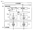
- FIG. 2 illustrates a block diagram of the communication device 10.
- the communication device 10 includes a transmission / reception unit 30, a communication processing unit 50, and an upper processing unit 70.
- various names may be abbreviated.
- the transmission / reception unit 30 is configured in conformity with the RF method and the PLC method, and includes an RF transmission / reception circuit 31 and a PLC transmission / reception circuit 32.
- the RF transmission / reception circuit 31 is responsible for transmission / reception of radio signals. For example, the RF transmission / reception circuit 31 converts a baseband signal (in other words, data included in the signal) input from the communication processing unit 50 into a radio signal and transmits it from the antenna. In addition, the RF transceiver circuit 31 converts a radio signal received via the antenna into a baseband signal that can be input to the communication processing unit 50 (in other words, according to the input signal format of the communication processing unit 50). The obtained baseband signal is input to the communication processing unit 50.
- a baseband signal in other words, data included in the signal
- the RF transceiver circuit 31 converts a radio signal received via the antenna into a baseband signal that can be input to the communication processing unit 50 (in other words, according to the input signal format of the communication processing unit 50).
- the obtained baseband signal is input to the communication processing unit 50.
- the PLC transmission / reception circuit 32 is responsible for transmission / reception of PLC signals. For example, the PLC transmission / reception circuit 32 superimposes the baseband signal input from the communication processing unit 50 on the voltage of the power line 5 as a PLC signal. The PLC transmission / reception circuit 32 extracts a PLC signal superimposed on the voltage of the power line 5 and converts it into a baseband signal that can be input to the communication processing unit 50. The obtained baseband signal is input to the communication processing unit 50.
- the communication processing unit 50 performs processing for mediating communication data between the upper processing unit 70 and the transmission / reception unit 30 and also performs various processing related to communication.
- the communication processing unit 50 provides a physical (PHY) layer function and a media access control (MAC) layer (or data link layer) function in an OSI (Open System Interconnection) reference model.
- PHY physical
- MAC media access control
- OSI Open System Interconnection
- the communication processing unit 50 includes a baseband processing unit (hereinafter also referred to as RF baseband processing unit) 51 for the RF transmission / reception circuit 31 and a baseband processing unit (hereinafter referred to as PLC) for the PLC transmission / reception circuit 32.
- Baseband processing means) 52 media access control processing means (hereinafter also referred to as MAC processing means) 53, selection means 54, and clock 55.
- the MAC processing means 53 provides a MAC layer function and performs so-called MAC processing.
- the MAC processing includes transmission processing and reception processing.
- a MAC header or further information is added to a PDU (Protocol Data Unit) (hereinafter also referred to as a packet) input from the upper processing unit 70 to add a MAC layer PDU (hereinafter referred to as a frame or a MAC frame).
- PDU Protocol Data Unit
- a MAC layer PDU hereinafter referred to as a frame or a MAC frame.
- the generated MAC frame is delivered to one of the baseband processing means 51 and 52.
- the reception process includes a process of interpreting the MAC frame restored by the baseband processing means 51 and 52 and a process according to the interpretation. For example, it is determined whether or not the received MAC frame is addressed to the own apparatus. Then, for the MAC frame addressed to the own device, a packet for delivery to the upper processing unit 70 is generated by removing the MAC header or the like. For example, when the received MAC frame includes a response (ACK) request, an ACK frame is generated and transmitted. In addition, a MAC frame addressed to another device may be discarded, but if it is transmitted, a signal can be relayed.
- ACK response
- the MAC processing may include other processing (hereinafter also referred to as MAC-related processing) in addition to processing of the MAC frame itself (hereinafter also referred to as MAC frame processing) like the transmission processing and reception processing described above.
- MAC-related processing include control processing (for example, control related to settings in the MAC processing unit 53 or the communication processing unit 50) according to control information included in the received MAC frame.
- the selection means 54 selectively links one of the RF baseband processing means 51 and the PLC baseband processing means 52 (in other words, exclusively) and functionally with the MAC processing means 53. That is, one of the baseband processing units 51 and 52 is validated with respect to the MAC processing unit 53. As a result, the MAC processing unit 53 transfers the MAC frame to the selected (in other words, validated) baseband processing unit 51 or 52.
- the selection of the baseband processing means 51 and 52 is performed according to a selection rule given in advance.
- the communication processing unit 50 selects the RF method and the PLC method in a time-sharing manner, and performs communication via the transmission / reception unit 30 using the selected communication method.
- the transmission frame is delivered from the MAC processing unit 53 to the effective baseband processing unit 51 or 52 via the selection unit 54. That is, the selection unit 54 delivers the transmission frame to the effective baseband processing unit 51 or 52.
- the selection means 54 instructs the MAC processing means 53 to the baseband processing means 51 or 52 to which the transmission frame is delivered.
- the transmission frame is delivered from the MAC processing unit 53 to the baseband processing unit 51 or 52 without passing through the selection unit 54.
- the received frame is delivered from the baseband processing means 51 or 52 to the MAC processing means 53 via the selection means 54.
- the RF baseband processing means 51 is provided for the RF transmission / reception circuit 31, and the PLC baseband processing means 52 is provided for the PLC transmission / reception circuit 32. Both of the baseband processing means 51 and 52 provide a physical layer function and perform so-called baseband processing.
- the baseband processing includes processing related to the baseband signal itself (hereinafter also referred to as baseband signal processing) and processing using the baseband signal (hereinafter also referred to as baseband related processing).
- Baseband signal processing includes transmission processing and reception processing.
- the transmission processing is performed by, for example, adding a PHY header, modulating data for wireless communication, adding synchronization control information (in this example, preamble and SFD), and the like.
- the PHY frame is input to the RF transceiver circuit 31 as a baseband signal that can be input to the RF transceiver circuit 31 (in other words, according to the input signal format of the RF transceiver circuit 31).
- the reception process includes, for example, a process of generating a MAC frame from a baseband signal input from the RF transmission / reception circuit 31 by detecting synchronization control information, demodulating data for wireless communication, deleting a PHY header, and the like.
- the baseband related processing for example, various types of processing (so-called carrier sense or the like) using the transmission / reception circuits 31 and 32 can be cited.
- the baseband processing by the PLC baseband processing means 52 is basically the same as that by the RF baseband processing means 51, but is appropriately modified according to the difference between the PLC method and the RF method.
- the processing means 51 to 54 can be realized by software, for example. Specifically, a processor (not shown) executes a program (stored in a storage means (not shown)) in which processing procedures for realizing various functions of the processing means 51 to 54 are described.
- the processor functions as the processing means 51-54.
- the processor may be a general-purpose CPU (Central Processing Unit) or a specialized DSP (Digital Signal Processor).
- the processing means 51 to 54 may be realized by a plurality of processors. Note that some or all of the various functions of the processing means 51 to 54 can be realized by hardware.
- the clock 55 counts a value at a predetermined period (that is, a predetermined frequency), and provides the count value as a time Tdev used in the apparatus (hereinafter referred to as an apparatus time) Tdev.
- a predetermined period that is, a predetermined frequency
- an oscillation period of a crystal oscillator can be adopted as the predetermined period, that is, the minimum time unit of the apparatus time Tdev, but other time lengths may be adopted.
- the in-device time Tdev is supplied to the processing means 51 to 54 in the example of FIG.
- the in-device time Tdev may be expressed by the count value itself, or may be expressed by converting the count value into information in, for example, general hours, minutes, and seconds.
- the clock 55 can be constituted by, for example, a so-called clock circuit, a real time clock (RTC) or the like. Further, for example, the clock 55 may be realized by a counter that counts the operation clock signal of the processor that functions as the processing means 51 to 54. The clock 55 may be externally attached to the processor package for the processing means 51 to 54 or may be incorporated in the package.
- RTC real time clock
- the upper processing unit 70 provides a higher layer function than the MAC layer (or data link layer) in the OSI reference model. For example, the upper processing unit 70 performs generation of a transmission packet, interpretation of a received packet, processing according to the interpretation, and the like.
- the host processing unit 70 is realized by software by a processor (general-purpose CPU is illustrated, not shown) that controls the entire processing in the communication device 10.
- the transmission / reception circuits 31 and 32 may have a configuration independent from each other (that is, an individual type), or a configuration in which a part of the circuit is shared (that is, a common type). Further, in the RF transmission / reception circuit 31, the transmission circuit and the reception circuit may be configured as either an individual type or a common type. The same applies to the PLC transmission / reception circuit 32.
- the communication processing unit 50 performs the shared circuit validation processing (selection of a circuit to be a user of the shared circuit, switching control of circuit connection, etc.) for any of the shared types is illustrated. More specifically, the selection unit 54 controls the transmission / reception unit 30 directly or indirectly (that is, via the baseband processing units 51 and 52).
- the baseband processing means 51 and 52 may be configured independently of each other, or may be configured to share a part of the processing means (in other words, functions). Further, in the RF baseband processing means 51, the transmission processing means and the reception processing means may be configured as either an individual type or a shared type. The same applies to the PLC baseband processing means 52.
- the selection unit 54 performs the sharing unit validation processing (selection of a processing unit serving as a user of the sharing unit, processing flow switching control, etc.) for any of the shared types is illustrated.
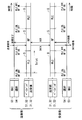
- ⁇ Communication operation> 3 to 5 illustrate communication operations performed by the communication device 10. 3 to 5, for the sake of simplicity, the MAC processing means 53 and the selection means 54 are shown together, and the baseband processing means 51 and 52 and the transmission / reception circuits 31 and 32 are shown together. ing.
- the communication device 10 performs synchronous communication using the time slot S.
- the selection means 54 defines the time slot S by dividing the in-device time Tdev (see FIG. 2) every predetermined time Tslot, and each time slot S includes an RF method and a PLC method. Assign one of these. That is, during the time slot S to which the RF system is assigned (hereinafter also referred to as RF time slot S), the RF baseband processing means 51 and the RF transceiver circuit 31 are validated, and the PLC baseband processing means 52 and the PLC transmission / reception circuit 32 are not used. During the time slot S to which the PLC system is assigned (hereinafter also referred to as the PLC time slot S), the situation is reversed.
- the RF method and the PLC method are assigned alternately. That is, the selection unit 54 selects a communication method according to a selection rule indicating that the RF method and the PLC method are alternately selected (and therefore in a predetermined order).
- the MAC processing unit 53 receives a packet including the transmission data DATA from the upper processing unit 70 (see FIG. 2), The frame is processed, and the MAC frame is delivered to the selection unit 54.
- the selection unit 54 inputs the MAC frame to the RF baseband processing unit 51 that is valid when the MAC frame is received.
- the selection unit 54 determines that the transmission of the MAC frame cannot be completed during the RF time slot S when the MAC frame is received, the output of the MAC frame is suspended until the start of the next PLC time slot S. You may comprise.
- the RF baseband processing means 51 that has received the MAC frame processes the MAC frame into a baseband signal and outputs the baseband signal to the RF transceiver circuit 31. As a result, a corresponding RF signal is output from the RF transceiver circuit 31.
- the RF transmission / reception circuit 31 receives the RF signal.
- the received signal is restored to a MAC frame by the RF transmission / reception circuit 31 and the RF baseband processing means 51.
- the restored MAC frame is delivered to the MAC processing unit 53 via the selection unit 54.
- the MAC processing means 53 processes the MAC frame into a packet and delivers it to the upper processing unit 70.
- the MAC processing means 53 interprets that the received MAC frame includes an ACK request, and thereby generates an ACK frame.
- the ACK frame is delivered to the selection means 54 and transmitted by the same processing as that on the transmission side. A series of processing is completed when the MAC processing means 53 on the side requesting ACK receives the ACK frame.
- ACK can be omitted even in unicast.
- RF communication is illustrated, but in the PLC time slot S, PLC communication is performed by the PLC baseband processing means 52 and the PLC transmission / reception circuit 32.
- the communication device 10 on the transmission side repeats the transmission process due to non-reception of ACK.
- Non-acknowledgment of ACK may occur, for example, because ACK has not reached the receiving side, or the transmission signal itself has not reached the receiving side.
- these signal non-arrivals are caused by, for example, a decrease in communication status, a mismatch in communication methods, and the like.
- the MAC processing unit 53 determines that the ACK has not been received even after the ACK waiting time (shorter than the time Tslot of the time slot S) has passed based on the in-device time Tdev, the MAC processing unit 53 The MAC frame is output again.
- the selection unit 54 may be configured to re-output the target MAC frame according to an instruction from the MAC processing unit 53.
- the selection unit 54 determines whether the received signal is an ACK frame (can be determined from information indicating the frame type in the received frame), so that the selection unit 54 itself instructs the MAC processing unit 53 You may perform a resending process without it.
- the upper limit number of retransmissions, the interval, etc. are set in advance, and are stored in, for example, a storage means that can be accessed by the MAC processing means 53 or the selection means 54.
- each communication device 10 can acquire the setting value by transmitting a setting value related to retransmission to the other communication device 10 serving as a slave by the communication device 10 functioning as a master regarding the setting of the maximum number of retransmissions. is there.
- the retransmission process may be performed over a plurality of time slots S. In this case, retransmission is performed by both RF and PLC. Conversely, the retransmission process may be stopped when the time slot S is switched.
- the same transmission data DATA is given the same sequence number (used to distinguish frames) and is transmitted by both RF and PLC.
- reception is successful in both RF and PLC as in the example of FIG. 5, a frame having a received sequence number (that is, a frame received later) is discarded.
- the discarding of received frames having the same sequence number is not limited to the example of FIG.
- the communication device 10 has a relay function, there is a possibility that a frame having the same sequence number is received twice or more. In such a case, the received frame may be discarded.
- the communication device 10 performs synchronous communication using the time slot S as described above.
- the period of the RF time slot S is shifted between the transmission side and the reception side, the communicable time is shortened, and as a result, communication efficiency is lowered.
- the period of the RF time slot S is the same (in other words, synchronized) on the transmission side and the reception side. The same applies to the PLC time slot S.
- the communication system 1 performs in-device time synchronization processing for matching the in-device time Tdev used for generating the time slot S between the communication devices 10 (in other words, synchronizing).
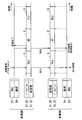
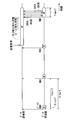
- FIG. 6 exemplifies the device time synchronization processing.
- the apparatus time synchronization processing 100 is divided into a time synchronization master process 101 and a time synchronization slave process 102, and these processes 101 and 102 are performed by different communication apparatuses 10.
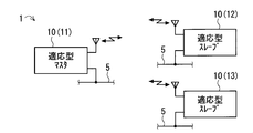
- the communication device 11 (see FIG. 1) performs the time synchronization master processing 101 and the communication devices 12 and 13 (see FIG. 1) perform the time synchronization slave processing 102 is illustrated.
- the communication device 11 is referred to as a first communication device 11 or time synchronization master device 11 related to time synchronization
- the communication devices 12 and 13 are referred to as second communication devices 12 and 13 or time synchronization slave device 12 related to time synchronization. 13 may also be referred to.
- the communication processing unit 50 starts the time synchronization master process 101 when a synchronization request for the device time Tdev is generated.
- a case where the time synchronization request is generated by the selection unit 54 is illustrated.
- the MAC processing unit 53 or the upper processing unit 70 may generate the time synchronization request. That is, the communication processing unit 50 acquires a time synchronization request by internal generation or external input.
- the time synchronization request may be generated periodically or at random time intervals.
- the MAC processing unit 53 When the selection unit 54 inputs the time synchronization request to the MAC processing unit 53, the MAC processing unit 53 generates a MAC frame for the time synchronization request.
- the MAC frame includes information indicating that it is a time synchronization request frame (that is, information on the frame type), information indicating that it is a broadcast (that is, information indicating that the destination is all the time synchronization slave devices 12 and 13), etc. Is included. For example, the set value of the unit time Tslot of the time slot S may be included.
- the MAC frame for time synchronization request is transformed into a PHY frame by the RF baseband processing means 51 effective at that time.
- the PHY frame is output as a baseband signal from the RF baseband processing means 51, and the baseband signal is converted into a radio signal and output from the RF transmission / reception circuit 31.
- the baseband signal for requesting time synchronization is also referred to as a time synchronization request signal.
- the time synchronization request signal 120 (more specifically, its bit string) includes a synchronization control portion 121 and a signal body portion subsequent to the synchronization control portion 121 in the same manner as a general PHY baseband signal. 122.
- the synchronization control portion 121 is information that the receiving side uses for detection of the time synchronization request signal 120, synchronization with the signal 120, and the like.
- the synchronization control portion 121 includes a preamble 123 and an SFD (Start Frame Delimiter) 124 that follows the preamble 123.
- SFD Start Frame Delimiter
- a bit string having a predetermined pattern is assigned to the preamble 123 in advance, and the same applies to the SFD 124.
- the signal body portion 122 basically includes a PHY header 125 and a PHY payload 126 that follows the PHY header 125.
- the PHY payload 126 illustrated in FIG. 6 from the PHY header 125 side, the MAC frame (here, the MAC frame for time synchronization request) 127, the time stamp 128, and the error detection code (here, CRC (Cyclic Redundancy Check)). 129) are lined up.
- CRC Cyclic Redundancy Check
- time synchronization request signal 120 elements 123, 124, 125, 128, and 129 other than the MAC frame 127 are added by the RF baseband processing means 51.
- the in-device time Tdev at the transmission start timing of the signal body portion 122 (in other words, the transmission end timing of the synchronization information portion 121) is set.
- the RF baseband processing means 51 detects the timing of switching from the bit string of the SFD 124 to the bit string of the PHY header 125 during the output of the time synchronization request signal 120, and the device internal time Tdev at the detection timing. Is obtained from the clock 55. Then, the RF baseband processing unit 51 adds the acquired in-device time Tdev as a time stamp 128 to the back of the MAC frame 127. Thereafter, the RF baseband processing means 51 calculates a CRC for the bit string from the beginning of the preamble 123 to the end of the time stamp 128, and adds the obtained CRC to the back of the time stamp 128.
- a time synchronization request signal 120 including the device time Tdev of the time synchronization master device 11 as the time stamp 128 is generated, and the time synchronization request signal 120 is transmitted to the time synchronization slave devices 12 and 13. Sent.
- the RF baseband processing means 51 specifies the position of the PHY header 125 and the like in the received bit string by using the bit pattern of the synchronization control portion 121 in general reception processing. For this reason, by using such a function, it is possible to detect the timing of switching from the SFD 124 to the PHY header 125 even in the time synchronization master processing 101.
- time synchronization slave processing 102 When receiving the time synchronization request signal 120, the time synchronization slave devices 12 and 13 perform time synchronization slave processing 102. Note that the time synchronization request signal 120 may be received directly from the time synchronization master device 11 or may be received via relay by another time synchronization slave device.
- the RF baseband processing means 51 detects the reception start timing of the signal body portion 122 (in other words, the reception end timing of the synchronization information portion 121) during reception of the time synchronization request signal 120, and The device internal time Tdev at the detection timing is acquired from the clock 55. Further, the RF baseband processing means 51 extracts the MAC frame 127 and the time stamp 128 from the time synchronization request signal 120. Then, the RF baseband processing means 51 delivers the in-device time Tdev acquired from the clock 55, the MAC frame 127, and the time stamp 128 to the MAC processing means 53.
- the MAC processing means 53 interprets that the received MAC frame is for a time synchronization request, the MAC processing means 53 is recorded in the internal device time Tdev acquired at the reception start timing of the signal body portion 122 and the received time stamp 128.
- the in-device time Tdev of the own device is calibrated according to the difference from the current time.
- the MAC processing unit 53 calibrates the current time of the clock 55 according to the difference.
- the time when the selection unit 54 holds the difference and calibrates the device time Tdev provided from the clock 55 with the difference is handled as the device time Tdev used for generating the time slot S or the like. Also good.
- the time synchronization slave devices 12 and 13 cannot determine whether or not the received signal is the time synchronization request signal 120 when the reception start timing of the signal main body portion 122 is detected.
- the in-device time Tdev may be acquired at the reception start timing of the signal body portion 122 for all received signals.
- the bit string indicating the frame type in the MAC frame 127 is acquired, it is possible to determine whether or not the received signal is the time synchronization request signal 120. That is, if it is determined that the signal is the time synchronization request signal 120, it is determined that the received signal includes the time stamp 128. Therefore, the time stamp 128 is extracted only when it is determined that the time synchronization request signal 120 is received.
- the MAC processing unit 53 performs calibration of the device time Tdev is illustrated above, it is possible to cause the selection unit 54 to calibrate the device time Tdev.
- the acquisition timing of the in-device time Tdev can be different between the time synchronization master process 101 and the time synchronization slave process 102.
- the acquisition timing of the device time Tdev in the time synchronization master processing 101 can be set to the transmission start timing of the preamble 123.
- the acquisition timing of the device time Tdev in the time synchronization slave processing 102 can be set to the end timing of the time synchronization request signal 120.
- the synchronization accuracy can be improved.
- the transmission start timing of the signal main body portion 122 (in other words, the transition timing from the synchronization control portion 121 to the signal main body portion 122) exists at the initial transmission of the time synchronization request signal 120. For this reason, there is a time margin from the timing to the end of transmission of the time synchronization request signal 120. Therefore, the process of including the time stamp 128 in the time synchronization request signal 120 can be performed with sufficient time.
- time synchronization slave devices 12 and 13 it may be difficult to accurately detect the start timing of the preamble 123 and the SFD 124.
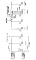
- FIG. 7 illustrates a selection rule 140 for selecting a communication method to be assigned to each time slot S.
- the selection rule 140 is a predetermined order selection rule for assigning the RF method and the PLC method to each time slot S in a preset order.
- the example of FIG. 7 is an alternate selection rule that alternately assigns the RF method and the PLC method exemplified in FIGS. 3 to 5, among the predetermined order selection rules.
- the selection preparation value J indicates, for example, to which time slot S the input device time Tdev belongs.
- the order value of the time slot S indicated by the selection preparation value J may not be an absolute value counted from the time of activation.
- the in-device time Tdev as an input key can be converted into the selection preparation value J as a hash value.
- the predetermined order selection rule is not limited to the alternating selection rule.
- the selection rule 140 involves the device time Tdev when selecting the communication method (in other words, it depends). For this reason, it is possible to synchronize the selection of communication methods between the communication devices 10 in which the device time Tdev is synchronized. For this reason, it is possible to improve a decrease in communication efficiency caused by a difference in communication method among the plurality of communication devices 10.
- two communication devices 11 and 12 may be operated as a time synchronization master device, and one communication device 13 may be operated as a time synchronization slave device.
- the time synchronization master device 12 performs internal time synchronization.
- the process 100 can be maintained. In other words, a system that can easily manage time synchronization can be provided.
- the time synchronization slave device 13 receives the time synchronization request signal 120 from the two time synchronization master devices 11 and 12.
- time synchronization slave device 13 executes the time synchronization slave processing 102 every time it receives the time synchronization request signal 120 without distinguishing between the time synchronization master devices 11 and 12.
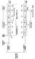
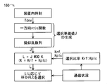
- the time synchronization master devices 11 and 12 set an authority level in the time synchronization request signal 120, and the time synchronization slave device 13 determines whether to execute the time synchronization slave processing 102 based on the authority level. Also good. Such an example will be described with reference to the flowchart of FIG.
- Different authority levels are assigned to the time synchronization master devices 11 and 12 in advance.
- the authority level is stored in a storage unit (not shown) of the communication processing unit 50, for example.
- Each of the time synchronization master devices 11 and 12 includes its own authority level in the MAC frame 127, the PHY header 125, and the like of the time synchronization request signal 120 (see the time synchronization master processing 101 in FIG. 8).
- the time synchronization slave device 13 compares the authority level of the received time synchronization request signal 120 with the highest authority level of the time synchronization request signal 120 received so far (see authority level determination processing 103 in FIG. 8). ).
- the maximum value is stored in, for example, a storage unit (not shown) of the communication processing unit 50 and is updated as appropriate.
- the time synchronization slave device 13 executes the time synchronization slave processing 102 according to the time synchronization request signal 120 received this time, on the condition that the current authority level is equal to or higher than the maximum value. . On the other hand, if the current authority level is lower than the maximum value, the time synchronization slave processing 102 is not executed for the time synchronization request signal 120 received this time.
- the time synchronization slave processing 102 is prevented from being frequently executed in the time synchronization slave device 13 even when the plurality of time synchronization master devices 11 and 12 exist. be able to.
- the frequent execution of the time synchronization slave processing 102 leads to a state where the in-device time Tdev is not stably determined (in other words, an uncertain state)
- such an uncertain state can be avoided.
- the time synchronization slave device 13 may perform a process of clearing (in other words, resetting) the highest authority level held by itself. For example, the time synchronization slave device 13 voluntarily executes the retained maximum value clear process at a predetermined timing. Alternatively, in place of or in addition to the voluntary execution, the retained maximum value clearing process is executed by an instruction transmitted by another communication device (for example, one of the time synchronization master devices 11 and 12) at a predetermined timing. It may be. In any example, the predetermined timing may be periodic or random.
- the in-device time synchronization process 100 can be maintained by the remaining time synchronization master device even when the time synchronization master device 11 having the highest authority level leaves the communication system 1. In other words, a system that can easily manage time synchronization can be provided.
- the communication device 11 executes the time synchronization master processing 101
- the communication device 12 executes the time synchronization slave processing 102
- the communication device 13 performs both the processing 101 and 102. It is also possible to execute.
- a communication device that can execute both processes 101 and 102 may be referred to as a time synchronization master / slave device.
- all of the communication devices 11 to 13 can be configured as time synchronization master / slave devices.
- the existence of a plurality of time synchronization master / slave devices 10 makes it possible to synchronize the in-device time Tdev over a wide range of the communication system 1. Such a point contributes to the expansion of the installation range of the communication device 10, that is, the area of the communication system 1.
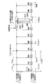
- FIG. 11 illustrates a random selection rule 150 according to the second embodiment regarding selection of a communication method to be assigned to each time slot S.
- the selection rule 150 is applied to the communication apparatus 10 exemplified in the first embodiment instead of or in addition to the predetermined order selection rule 140 (see FIG. 7).
- the selection rule to be used is determined based on, for example, initial settings, predetermined conditions, instructions from other communication devices 10, and the like.
- the example of FIG. 11 is the same as the example of FIG. 7 (predetermined order selection rule 140) except that the selection preparation value J is generated as follows. That is, in the example of FIG. 11, the device internal time Tdev is used as an input key and input to a one-way hash function defined in advance for obtaining the selection preparation value J. Then, a pseudorandom number is generated using the obtained hash value as a seed, and the obtained pseudorandom value is adopted as the selection preparation value J. As a result, the communication method assigned to each time slot S is randomly selected from a plurality of communication methods (here, RF method and PLC method).
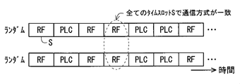
- the alternate selection rule 140 illustrated in FIG. 7 may cause a state where the communication methods do not match between the communication devices 10 as shown in FIG. Communication is not possible in such a state.
- FIG. 13 illustrates the case where the communication partner adopts the alternate selection rule 140, but is not limited to this example.
- the communication partner may adopt the random selection rule 150.
- each communication device 10 can obtain the same pseudo-random value. This is because the device time Tdev is involved in the generation of the pseudo random number. As a result, as illustrated in FIG. 14, the communication methods of the respective time slots S continuously match. For this reason, it is possible to improve a decrease in communication efficiency caused by a difference in communication method between the communication devices 10.
- whether or not to perform the in-device time synchronization processing 100 is arbitrary. However, the effect of the combination of the time synchronization processing 100 and the random selection rule 150 is as described above.
- FIG. 15 illustrates an adaptive selection rule 160 according to the third embodiment regarding selection of a communication method to be assigned to each time slot S.
- the selection rule 160 is the communication exemplified in the first embodiment in place of the selection rules 140 and 150 (see FIGS. 7 and 11) or in addition to at least one of the selection rules 140 and 150. Applies to device 10.
- the selection rule to be used is based on the initial setting, the predetermined condition, an instruction from another communication device 10, and the like. It is determined.
- the adaptive selection rule 160 is a rule for selecting a communication method with a better communication state among a plurality of communication methods (here, RF method and PLC method) with a higher selection ratio.
- the adaptive selection rule 160 illustrated in FIG. 15 applies communication status information to the random selection rule 150 illustrated in FIG. Therefore, according to such an example, the adaptive selection rule 160 generates a pseudorandom value based on the in-device time Tdev and selects the first rule (selecting the communication method associated with the pseudorandom value) ( Corresponding to the random selection rule 150) and a second rule that changes the correspondence between the pseudo-random number value and the communication method according to the communication status.
- a selection ratio index value Krf: Kplc is selected so that a communication system with a better communication status is selected with a higher selection ratio between the RF system and the PLC system. Is changed according to the communication status of RF and PLC, and the correspondence between the remainder L and the communication method is also changed according to the communication status.
- the communication status investigation result is represented by, for example, one of three-level evaluations that RF is better, RF and PLC are comparable, and PLC is better.
- the evaluation that RF is better and the evaluation that PLC is better may be subdivided according to the degree.
- the degree of communication status can be obtained from, for example, the calculation formula ⁇ value representing the RF communication status ⁇ / ⁇ value representing the PLC communication status ⁇ .
- the selection ratio Krf: Kplc is prepared in advance for each evaluation level of the communication status, and the correspondence between the remainder value L and the communication method is also prepared in advance. According to this, the selection ratio Krf: Kplc and the association are selected according to the evaluation level, and a communication method is assigned to each time slot S according to the selected ratio.
- the communication status by evaluating parameters useful for grasping the communication status.
- the parameters include a carrier sense result, an ACK response rate, the number of retransmissions, and the like.
- the communication status of each of RF and PLC is acquired. Then, by comparing the RF communication status and the PLC communication status, it is possible to determine a good communication method, determine an evaluation level, and the like. Note that the investigation of the communication status may be performed periodically or at random time intervals.
- the parameter collection, evaluation, and the like are performed by the selection unit 54 using the adaptive selection rule 160.
- the MAC processing unit 53 performs these processes, and selects the processing result. May be provided.
- the communication status is investigated by the communication processing unit 50.
- a suitable communication method is appropriately selected according to the communication status, so that communication efficiency, reliability, and the like can be improved.
- the adaptive selection rule 160 illustrated in FIG. 15 uses the random selection rule 150, the above-described effect produced by the random selection rule 150 can be obtained.
- selection rules other than the random selection rule 150 may be used.
- a plurality of patterns of predetermined order selection rules may be prepared in advance, and one of them may be used according to the communication status.
- the communication status may be investigated by each communication device 10 in the communication system 1.
- the communication device 11 may investigate the communication status and distribute the survey result to the other communication devices 12 and 13 by broadcasting. In this case, the communication device 11 acquires the communication status by investigating the communication status, whereas the communication devices 12 and 13 acquire the communication status by receiving the check result from the communication device 11.
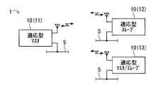
- the communication device 11 is referred to as the first communication device 11 or the adaptive master device 11 relating to the adaptive selection rule, and the communication devices 12 and 13 are referred to as the second communication device 12 or 13 relating to the adaptive selection rule or the adaptive type. It may also be called slave devices 12 and 13 (see FIG. 17).
- the processing load and the device configuration can be reduced.
- the communication state investigation result may be received directly from the adaptive master device 11 or may be received via a relay by another adaptive slave device.
- a plurality of adaptive master devices 10 may exist.
- a communication device 10 that can operate as an adaptive master device and can also operate as an adaptive slave device (hereinafter also referred to as an adaptive master / slave device) may be provided.
- FIG. 18 illustrates a case where the communication device 13 is an adaptive master / slave device.
- whether or not to perform the in-device time synchronization processing 100 (see FIG. 6) according to the first embodiment is arbitrary.
- the adaptive selection rule 160 uses the random selection rule 150, the combination of the in-device time synchronization processing 100 and the adaptive selection rule 160 is useful.
- FIG. 19 relates to a communication apparatus compliant only with the RF system.
- the communication apparatus on the data (DATA) receiving side activates the communication function intermittently with a predetermined intermittent period Titmrf, and transmits the beacon RN0 (in other words, issues it).
- the beacon RN0 is a beacon for notifying that the receiving side device has started a communicable state.
- a beacon for use may be referred to as a receiving beacon or the like.
- the receiving side beacon RN0 is broadcast.
- the receiving side apparatus After transmitting the beacon RN0, the receiving side apparatus waits for a response to the beacon RN0 during a predetermined beacon response waiting time Tircrf.
- the code Tircrf is also used for the beacon response waiting period. The same usage may be adopted for other codes.
- the data reception side device transmits a response RACK to the SREQ to the data transmission side device, thereby establishing a communication link.
- the receiving side apparatus receives DATA from the transmitting side apparatus, and transmits a response DACK to the transmitting side apparatus when the reception ends.
- the data reception side device stops the communication function.
- the data transmission side device activates the communication function and forms a reception waiting state for the beacon RN0. Then, when receiving the beacon RN0 issued by the communication device that is the transmission destination, the transmission side device transmits a transmission request SREQ to the reception side device.
- the transmission side apparatus establishes a communication link by receiving a response RACK to the SREQ. After the communication link is established, transmission of DATA is started, and transmission is completed when DACK is received. After the transmission is completed, the transmission side device stops the communication function. If the beacon RN0 cannot be received during the predetermined maximum beacon waiting time (in other words, the maximum link establishment waiting time), a transmission error (in other words, a timeout) occurs.
- FIG. 20 illustrates a schematic configuration of a communication system 1D according to the fourth embodiment.
- the communication system 1D includes three communication devices 10D.
- the number of communication devices 10D is not limited to this example.
- FIG. 21 illustrates a block diagram of the communication device 10D
- FIG. 22 illustrates a communication operation of the communication device 10D
- the communication device 10D has a configuration in which the communication processing unit 50 is changed to the communication processing unit 50D in the communication device 10 illustrated in FIG.
- the communication processing unit 50D has a configuration in which the MAC processing unit 53 and the selection unit 54 in the communication processing unit 50 illustrated in FIG. 2 are changed to the MAC processing unit 53D and the selection unit 54D, respectively.
- the other configuration of the communication device 10D is basically the same as that of the communication device 10.
- the communication processing unit 50D basically performs the same processing as the communication processing unit 50, but performs processing according to intermittent communication.
- the communication processing unit 50D performs at least one of a beacon transmission process 201 (see FIG. 22) and a beacon response process 202 (see FIG. 22).
- the communication device 10D that performs the beacon transmission process 201 may be referred to as a first communication device related to beacon use
- the communication device 10D that performs the beacon response process 202 may be referred to as a second communication device related to beacon use.
- a first communication device related to beacon use the communication device 10D that performs the beacon response process 202
- a second communication device related to beacon use Good.
- the processes 201 and 202 are switched as appropriate.
- the beacon transmission process 201 is performed, and when a transmission request is issued from the host processing unit 70 (in other words, when a packet to be transmitted is generated), the beacon response process 202 is switched.
- one communication device 10D can operate as a data receiving side and can also operate as a data transmitting side.
- the beacon transmission process 201 is a process for intermittently transmitting the receiving beacon RN0.
- either the RF method or the PLC method is selected according to a predetermined selection rule, and the receiving side beacon RN0 is transmitted by the selected communication method.
- the receiving side beacon RN0 is broadcast.
- an alternate selection rule for alternately selecting the RF method and the PLC method is adopted, and the beacon RN0 is transmitted by the PLC method during the RF method stop period (in other words, the non-selection period) Tnslrf. Is performed once.
- FIG. 22 shows the beacon transmission intermittent period Titmrf, beacon response waiting time Tircrf, and non-selection time Tnslrf with the same time length as in the comparative example of FIG. Yes.
- a case where the PLC beacon RN0 is transmitted at the timing of a half cycle of the RF method intermittent cycle Titmrf is illustrated.
- beacon response waiting time Tircplc for the PLC type beacon RN0 has the same time length as the beacon response waiting time Tircrf for the RF type beacon RN0 is illustrated.
- the set values of various times are not limited to the above examples.
- the PLC system link maintenance time Tlnkplc may have the same time length as the RF system link maintenance time Tlnkrf (see FIG. 19), or the link maintenance time Tlnkrf may vary depending on the communication speed. May have a different length of time. Further, the time lengths of these link maintenance times Tlnkplc and Tlnkrf may be predetermined fixed values or variable values corresponding to the size of the received DATA.
- the receiving beacon RN0 is generated as follows. For example, the end of the non-selection time Tnslrf is notified to the communication processing unit 50D by a timer (not shown) that measures the non-selection time Tnslrf and the like. Then, the MAC processing unit 53D generates a MAC frame for the beacon RN0 (hereinafter also referred to as a beacon frame) based on the notification from the timer. The generated beacon frame is transmitted as an RF beacon RN0 or a PLC beacon RN0 in accordance with the communication method selected by the selection unit 54D.
- the selecting unit 54D selects a communication method used for transmitting the beacon RN0 according to an alternate selection rule for alternately selecting the RF method and the PLC method.
- the beacon response waiting times Tircrf, Tircplc, link maintenance times Tlnkrf, Tlnkplc, etc. are measured by the device time Tdev provided by the clock 55.
- the timer may be used.
- the beacon response process 202 is a process of attempting to receive the receiving beacon RN0 and responding to the beacon RN0.
- the beacon response processing 202 attempts to receive the beacon RN0 by switching between the RF method and the PLC method, and responds to the beacon RN0 by the communication method that has received the beacon RN0 (here, the transmission request SREQ is transmitted). To do).
- the beacon response process 202 is started in response to a transmission request from the upper processing layer 70, for example.
- the switching between the RF system and the PLC system is performed, for example, by the selection unit 54D in accordance with an alternate selection rule used in the beacon transmission process 201.
- the switching between the RF method and the PLC method is performed in a time shorter than the transmission cycle Titm of the beacon RN0.
- the switching of the communication method in the beacon response process 202 is not limited to these examples.
- the communication system switching cycle Titm, the beacon waiting maximum time, and the like are measured by the in-device time Tdev provided by the clock 55.
- the timer may be used.
- beacon response process 202 RACK transmission / reception, DATA transmission / reception, and DACK transmission / reception are performed as in the comparative example of FIG.
- the data transmission side must wait for data transmission until the beacon RN0 is received, in other words, until the communication link is established.
- a waiting state causes a communication delay.
- the delay time can be as long as the RF intermittent cycle Titmrf.
- the beacon RN0 is transmitted by the PLC method even during the non-selection period of the RF method, so that the transmission interval of the beacon RN0 can be shortened.
- the transmission interval of the beacon RN0 is halved compared to the example of FIG.
- the side receiving the beacon RN0 switches between the RF method and the PLC method and waits for the arrival of the beacon RN0, so that it can cope with the beacon RN0 transmitted by any communication method.
- the communication system 1D it is possible to reduce the waiting time for receiving the beacon RN0 (in other words, waiting for establishment of the communication link) compared to the comparative example that does not have the PLC method. Communication delay caused by waiting time can be improved. Thereby, communication efficiency, reliability, and the like can be improved.
- the beacon RN0 may be transmitted twice by the PLC method during the non-selection period Tnslrf of the RF method.
- This example can be realized by selecting a communication method according to a predetermined order selection rule that defines a predetermined order of RF ⁇ PLC ⁇ PLC as one cycle.
- you may perform the beacon transmission by a PLC system 3 times or more.
- the transmission interval Titm of the beacon RN0 can be further shortened, so that the link establishment waiting time and the communication delay caused thereby can be further improved. Further, such an effect can be obtained without increasing the number of types of communication methods.
- the RF transmission / reception circuit 31 is driven by a battery (not shown), and the PLC transmission / reception circuit 32 is driven by the supply power (external supply power) of the power line 5 (see FIG. 20) used for the PLC. Conceivable. According to this example, even if the number of times the beacon RN0 is transmitted increases, it is possible to extend the battery.
- the RF transmission / reception circuit 31 can be driven by a battery (and may be driven by external power supply), for example, in a place where there is no power line or where it is difficult to lay a power line
- the RF An example in which only the transmission / reception circuit 31 is driven by a battery is conceivable.
- the RF transmission / reception circuit 31 can be driven by both the battery and the external supply power, for example, when Hirao uses the supply power of the power line 5 and the supply power of the power line 5 is interrupted due to a power failure or the like.
- An example of switching to a battery is conceivable. According to this example, RF communication can be secured.
- any of a battery, an external power supply, and a combination thereof can be adopted as a power supply mode for the communication processing unit 50D and the like.
- the RF method is the same as in the comparative example. Will only use. Even in such a case, the communication processing unit 50D performs both the RF process and the PLC process as described above.
- the communication processing unit 50D is also equipped with an operation mode for performing only the RF method processing. You may make it switch.
- the beacon RN0 is transmitted at equal intervals in time by the RF method and the PLC method.
- the beacon RN0 can be transmitted at unequal intervals.
- the beacon transmission process 201 intermittently transmits the beacon RN0 by the first communication method and intermittently transmits the beacon RN0 by the second to Nth communication methods during the non-selection period of the first communication method. It is a process to transmit.
- the beacon RN0 is transmitted using at least one of the second to Nth communication methods twice or more. Also good.
- the beacon response process 202 is a process of attempting to receive the beacon RN0 by switching the first to Nth communication methods and responding to the beacon RN0 with the communication method that has received the beacon RN0.
- N 2
- the first communication method is the RF method
- the second communication method is the PLC method.
- the present invention is limited to this example. is not.
- intermittent communication there is a period in which all communication methods are in a non-selected state, and the communication processing unit 50D and the transmission / reception unit 30 may be in a so-called sleep state during such a period. Although it is possible to continue the power supply and maintain the operating state, the power consumption can be reduced by adopting the sleep state.
- the clock 55 may be configured to be in a sleep state together with the MAC processing unit 53D, or the clock 55 may be configured to continue to operate even when the MAC processing unit 53D is in a sleep state. Good.
- the in-device time Tdev is reset every time the sleep state occurs, and is therefore not held.
- the in-device time Tdev can be held. For example, by providing a power source for the clock 55 separately from a power source for the MAC processing unit 53D and the like, it is possible to keep the clock 55 operating.
- the communication method is selected according to a predetermined order selection rule (including an alternate selection rule).
- a random selection rule 150 see FIG. 11
- an adaptive selection rule see FIG. 15
- the beacon RN0 by the first communication method in the above, the RF method is exemplified
- the selection rules 140, 150, and 160 exemplified in the first to third embodiments depend on the in-device time Tdev. For this reason, in the configuration in which the in-device time Tdev is held, the selection rules 140, 150, and 160 can be applied. On the other hand, in a configuration in which the in-device time Tdev is not held, for example, a predetermined set value may be used instead of the in-device time Tdev.
- the beacon transmission process 201 and the beacon response process 202 use the same selection rule.
- processing 201 and 202 may use different selection rules.
- the communication system 1D includes only the communication system 10D that complies with a plurality of communication methods is exemplified.
- the communication system 1D can include a communication device that performs intermittent communication using one communication method.
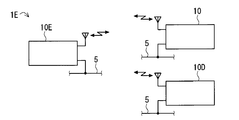
- FIG. 24 illustrates a schematic configuration of a communication system 1E according to the fifth embodiment.
- the communication system 1E includes the communication device 10 according to any of the first to third embodiments and the communication device 10D according to the fourth embodiment, and according to the fifth embodiment.
- a communication device 10E is included. That is, in the communication system 1E, the communication device 10 that performs synchronous communication and the communication device 10D that performs asynchronous communication are mixed, and in view of this, the communication device 10E is configured to support both synchronous communication and asynchronous communication.
- the number of communication apparatuses 10, 10D, and 10E is not limited to the example of FIG.
- FIG. 25 illustrates a block diagram of the communication device 10E.
- the communication device 10E has a configuration in which the communication processing unit 50 is changed to the communication processing unit 50E in the communication device 10 illustrated in FIG.
- the communication processing unit 50E has a configuration in which the MAC processing unit 53 and the selection unit 54 in the communication processing unit 50 illustrated in FIG. 2 are changed to the MAC processing unit 53E and the selection unit 54E, respectively.
- the other configuration of the communication device 10E is basically the same as that of the communication device 10.
- the MAC processing means 53E generally has the function of the MAC processing means 53 (see FIG. 2) and the function of the MAC processing means 53D (see FIG. 21), and appropriately provides various functions.
- both the MAC processing means 53 and 53D are provided, and the MAC processing means 53E can be configured by the cooperation of the both means 53 and 53D.
- the MAC processing means 53E can be configured by the cooperation of the both means 53 and 53D.
- overlapping functions may be omitted from the MAC processing unit 53D.
- the selection means 54E has the function of the selection means 54 (see FIG. 2) and the function of the selection means 54D (see FIG. 21), and provides various functions as appropriate.
- the communication device 10E holds the device time Tdev. Therefore, it is possible to perform the synchronization process 100 (see FIG. 6) of the in-device time Tdev.
- a configuration in which the apparatus time synchronization processing 100 is not performed can be employed. In any case, in FIG. 25, the description about the in-device time synchronization processing (see FIG. 2) is omitted.
- synchronous communication processing 301 and asynchronous communication processing 302 are performed in parallel by synchronous / asynchronous parallel processing 300.
- the synchronous communication time slot S is controlled by the synchronous communication process 301
- the transmission of the asynchronous communication beacon RN0 is controlled by the asynchronous communication process 302.
- the beacon RN0 is intermittently transmitted by the communication method selected in the synchronous communication process 301. Further, according to the example of FIG. 27, the beacon RN0 is transmitted in synchronization with the start timing of the time slot S. In the example of FIG. 27, the transmission period of the beacon RN0 is set to three times the time length of the time slot S, but the present invention is not limited to this example. For example, the beacon RN0 may be transmitted in each time slot S.
- the selection unit 54E functions in the same manner as the selection unit 54, the time slots S to which any communication method is assigned are sequentially generated.
- the alternate selection rule is illustrated in FIG. 27, it is not limited to this example.
- the MAC processing means 53E functions in the same manner as the MAC processing means 53, so that synchronous communication can be performed in each time slot S. Further, when the MAC processing unit 53E generates a beacon frame in the same manner as the MAC processing unit 53D, the beacon RN0 is transmitted by the communication method assigned to the time slot S at that time.
- the MAC processing unit 53E acquires the switching timing of the time slot S from the selection unit 54E, and outputs a beacon frame in accordance with the switching timing, so that the beacon is synchronized with the start timing of the time slot S.
- RN0 can be transmitted.
- the selection unit 54E may adjust the transmission timing of the beacon RN0 by holding the beacon frame input to the baseband processing unit 51 or 52 until the start timing of the next time slot S.
- communication link maintenance times Tlnkrf and Tlnkplc (see FIGS. 19 and 22) for asynchronous communication are set to be equal to or less than the time length of the time slot S. Thereby, asynchronous communication can be completed in each time slot S, and the reliability of asynchronous communication can be ensured. Further, by transmitting the beacon RN0 at the start timing of the time slot S as described above, the communication link maintenance times Tlnkrf and Tlnkplc can be increased.
- the control of the time slot S may be interrupted and the beacon response process 202 (see FIG. 22) may be performed.
- the communication device 10 can communicate with the communication device 10 through the synchronous communication processing 301, and can communicate with the communication device 10D through the asynchronous communication processing 302. That is, according to the communication device 10E, synchronous communication using the time slot S and asynchronous communication using the beacon RN0 can be mixed in a communication system using a plurality of communication methods in a time division manner.
- the communication device 10D that performs the beacon transmission process 201 is referred to as a first communication device related to the use of a beacon
- the communication device 10D that performs the beacon response process 202 is the first communication device related to the use of a beacon. 2 communication device. If this is followed, the communication device 10E is included in the first communication device. In view of further performing the synchronous communication processing 301, the communication device 10E may be referred to as a third communication device related to the use of a beacon.
- the communication system 1E includes only the communication systems 10 and 10D conforming to a plurality of communication methods is illustrated.
- the communication system 1E can also include a communication device that performs intermittent communication using one communication method.
- a security monitoring system can be constructed by employing a camera or a human sensor as the sensor.
- a telemeter system can be constructed
- a control system can be constructed by configuring a controller with a communication function by mounting a control function of an object to be controlled (for example, a lighting device) on the communication device.
Landscapes
- Engineering & Computer Science (AREA)
- Computer Networks & Wireless Communication (AREA)
- Signal Processing (AREA)
- Quality & Reliability (AREA)
- Mobile Radio Communication Systems (AREA)
- Synchronisation In Digital Transmission Systems (AREA)
Priority Applications (1)
| Application Number | Priority Date | Filing Date | Title |
|---|---|---|---|
| US14/360,349 US9716561B2 (en) | 2011-11-24 | 2012-10-30 | Communication system, and communication device |
Applications Claiming Priority (2)
| Application Number | Priority Date | Filing Date | Title |
|---|---|---|---|
| JP2011-256052 | 2011-11-24 | ||
| JP2011256052A JP5840467B2 (ja) | 2011-11-24 | 2011-11-24 | 通信システムおよび通信装置 |
Publications (1)
| Publication Number | Publication Date |
|---|---|
| WO2013077148A1 true WO2013077148A1 (ja) | 2013-05-30 |
Family
ID=48469596
Family Applications (1)
| Application Number | Title | Priority Date | Filing Date |
|---|---|---|---|
| PCT/JP2012/078004 Ceased WO2013077148A1 (ja) | 2011-11-24 | 2012-10-30 | 通信システムおよび通信装置 |
Country Status (3)
| Country | Link |
|---|---|
| US (1) | US9716561B2 (enExample) |
| JP (1) | JP5840467B2 (enExample) |
| WO (1) | WO2013077148A1 (enExample) |
Cited By (2)
| Publication number | Priority date | Publication date | Assignee | Title |
|---|---|---|---|---|
| DE112016006244T5 (de) | 2016-02-24 | 2018-09-27 | Mitsubishi Electric Corporation | Zeitsynchrone slave-vorrichtung und kommunikationssteuerverfahren |
| CN111130681A (zh) * | 2019-12-10 | 2020-05-08 | 中国信息通信研究院 | 一种噪声传递特性确定方法和装置 |
Families Citing this family (3)
| Publication number | Priority date | Publication date | Assignee | Title |
|---|---|---|---|---|
| JP6326907B2 (ja) * | 2014-03-27 | 2018-05-23 | 富士通株式会社 | 伝送システム、伝送装置及びクロック同期方法 |
| TWI587697B (zh) * | 2015-04-29 | 2017-06-11 | 瑞昱半導體股份有限公司 | 多媒體同步系統與方法 |
| CN108631897B (zh) | 2017-03-17 | 2019-10-22 | 杭州海康威视数字技术股份有限公司 | 一种网络校时方法及装置 |
Citations (2)
| Publication number | Priority date | Publication date | Assignee | Title |
|---|---|---|---|---|
| WO2002091683A1 (fr) * | 2001-05-08 | 2002-11-14 | Sony Corporation | Systeme de radiocommunication, station de controle, appareil de communication, procede de controle de communication, procede de radiocommunication, et programme de controle de communication |
| JP2006109433A (ja) * | 2004-10-01 | 2006-04-20 | Mitsubishi Electric Research Laboratories Inc | 無線通信ネットワークにおいて送信機の送信クロックと受信機の受信クロックとを同期させるための方法 |
Family Cites Families (7)
| Publication number | Priority date | Publication date | Assignee | Title |
|---|---|---|---|---|
| US20050085259A1 (en) * | 2003-10-15 | 2005-04-21 | Conner W. S. | Technique to coordinate wireless network over a power line or other wired back channel |
| JP4763334B2 (ja) | 2005-04-28 | 2011-08-31 | ルネサスエレクトロニクス株式会社 | 無線アドホック通信システム及び無線アドホック通信システムにおける通信端末の同期化方法 |
| TWI276334B (en) * | 2005-09-16 | 2007-03-11 | Ind Tech Res Inst | Methods for allocating transmission bandwidths of a network |
| US20070153815A1 (en) * | 2005-12-30 | 2007-07-05 | George Geeyaw She | System and Method For Establishing And Maintaining Simultaneous Operation of Asynchronous and Isochronous Communications |
| KR100954170B1 (ko) * | 2008-02-27 | 2010-04-20 | 부산대학교 산학협력단 | 다중 rf 수신장치 및 이를 이용한 위치 측정 방법 |
| US8102787B2 (en) * | 2008-06-17 | 2012-01-24 | Samsung Electronics Co., Ltd. | MAC layer timestamping approach for emerging wireless sensor platform and communication architecture |
| JP5328250B2 (ja) | 2008-07-22 | 2013-10-30 | 株式会社メガチップス | 通信装置および電子装置 |
-
2011
- 2011-11-24 JP JP2011256052A patent/JP5840467B2/ja not_active Expired - Fee Related
-
2012
- 2012-10-30 WO PCT/JP2012/078004 patent/WO2013077148A1/ja not_active Ceased
- 2012-10-30 US US14/360,349 patent/US9716561B2/en not_active Expired - Fee Related
Patent Citations (2)
| Publication number | Priority date | Publication date | Assignee | Title |
|---|---|---|---|---|
| WO2002091683A1 (fr) * | 2001-05-08 | 2002-11-14 | Sony Corporation | Systeme de radiocommunication, station de controle, appareil de communication, procede de controle de communication, procede de radiocommunication, et programme de controle de communication |
| JP2006109433A (ja) * | 2004-10-01 | 2006-04-20 | Mitsubishi Electric Research Laboratories Inc | 無線通信ネットワークにおいて送信機の送信クロックと受信機の受信クロックとを同期させるための方法 |
Cited By (4)
| Publication number | Priority date | Publication date | Assignee | Title |
|---|---|---|---|---|
| DE112016006244T5 (de) | 2016-02-24 | 2018-09-27 | Mitsubishi Electric Corporation | Zeitsynchrone slave-vorrichtung und kommunikationssteuerverfahren |
| DE112016006244B4 (de) | 2016-02-24 | 2020-01-23 | Mitsubishi Electric Corporation | Zeitsynchrone slave-vorrichtung und kommunikationssteuerverfahren |
| CN111130681A (zh) * | 2019-12-10 | 2020-05-08 | 中国信息通信研究院 | 一种噪声传递特性确定方法和装置 |
| CN111130681B (zh) * | 2019-12-10 | 2021-10-08 | 中国信息通信研究院 | 一种噪声传递特性确定方法和装置 |
Also Published As
| Publication number | Publication date |
|---|---|
| US20140314073A1 (en) | 2014-10-23 |
| US9716561B2 (en) | 2017-07-25 |
| JP2013110670A (ja) | 2013-06-06 |
| JP5840467B2 (ja) | 2016-01-06 |
Similar Documents
| Publication | Publication Date | Title |
|---|---|---|
| WO2013077149A1 (ja) | 通信システムおよび通信装置 | |
| JP5297130B2 (ja) | ワイヤレスセンサネットワークでの混信軽減のためのシステムおよび方法 | |
| EP2915260B1 (en) | Fast frequency-hopping schedule recovery | |
| US8654758B2 (en) | Synchronization within wireless devices | |
| US8660110B2 (en) | Reduced power synchronization of wireless devices | |
| JP5840467B2 (ja) | 通信システムおよび通信装置 | |
| JP2008537871A (ja) | 衝突回避プロトコルを有する無線通信システム | |
| EP2200207A1 (en) | Error correction scheme in a hearing system wireless network | |
| US8908536B2 (en) | Density-based power outage notification transmission scheduling in frequency-hopping networks | |
| JP2012039446A (ja) | 通信システム及び通信装置 | |
| JP2013074527A (ja) | 伝送装置、伝送システム及び通信制御方法 | |
| EP2165471A1 (en) | Synchronizing timeslots in a wireless communication protocol | |
| WO2008127688A1 (en) | Synchronizing timeslots in a wireless communication protocol | |
| CN109314975B (zh) | 无线通信网络中的通信节点的操作方法、关联的通信节点、通信系统和存储系统 | |
| CN113994719B (zh) | 通信系统、通信方法及通信装置 | |
| JP5840468B2 (ja) | 通信システムおよび通信装置 | |
| JP2011101276A (ja) | 無線通信装置 | |
| JP5840469B2 (ja) | 通信システムおよび通信装置 | |
| JP2012114815A (ja) | 位相同期装置および位相同期方法 | |
| EP2568632B1 (en) | Synchronization within wireless devices | |
| JP2025520151A (ja) | 効率的なユニキャストスーパーフレーム通信 | |
| EP2533439A2 (en) | Reduced power synchronisation of wireless device | |
| Ferrari | Enabling dependable communication in cyber-physical systems with a wireless bus | |
| Torfs et al. | WBAN implementation on Magnetic Induction Radio IC for medical remote monitoring | |
| WO2014203449A1 (ja) | 通信システム、通信システムの制御方法、送信装置、及び受信装置 |
Legal Events
| Date | Code | Title | Description |
|---|---|---|---|
| 121 | Ep: the epo has been informed by wipo that ep was designated in this application |
Ref document number: 12852399 Country of ref document: EP Kind code of ref document: A1 |
|
| WWE | Wipo information: entry into national phase |
Ref document number: 14360349 Country of ref document: US |
|
| NENP | Non-entry into the national phase |
Ref country code: DE |
|
| 122 | Ep: pct application non-entry in european phase |
Ref document number: 12852399 Country of ref document: EP Kind code of ref document: A1 |