WO2013076892A1 - 電力用ガス絶縁機器 - Google Patents
電力用ガス絶縁機器 Download PDFInfo
- Publication number
- WO2013076892A1 WO2013076892A1 PCT/JP2012/005650 JP2012005650W WO2013076892A1 WO 2013076892 A1 WO2013076892 A1 WO 2013076892A1 JP 2012005650 W JP2012005650 W JP 2012005650W WO 2013076892 A1 WO2013076892 A1 WO 2013076892A1
- Authority
- WO
- WIPO (PCT)
- Prior art keywords
- gas
- pressure
- arc
- insulating
- flow path
- Prior art date
Links
Images


Classifications
-
- H—ELECTRICITY
- H01—ELECTRIC ELEMENTS
- H01H—ELECTRIC SWITCHES; RELAYS; SELECTORS; EMERGENCY PROTECTIVE DEVICES
- H01H33/00—High-tension or heavy-current switches with arc-extinguishing or arc-preventing means
- H01H33/70—Switches with separate means for directing, obtaining, or increasing flow of arc-extinguishing fluid
- H01H33/88—Switches with separate means for directing, obtaining, or increasing flow of arc-extinguishing fluid the flow of arc-extinguishing fluid being produced or increased by movement of pistons or other pressure-producing parts
- H01H33/90—Switches with separate means for directing, obtaining, or increasing flow of arc-extinguishing fluid the flow of arc-extinguishing fluid being produced or increased by movement of pistons or other pressure-producing parts this movement being effected by or in conjunction with the contact-operating mechanism
- H01H33/91—Switches with separate means for directing, obtaining, or increasing flow of arc-extinguishing fluid the flow of arc-extinguishing fluid being produced or increased by movement of pistons or other pressure-producing parts this movement being effected by or in conjunction with the contact-operating mechanism the arc-extinguishing fluid being air or gas
-
- H—ELECTRICITY
- H05—ELECTRIC TECHNIQUES NOT OTHERWISE PROVIDED FOR
- H05K—PRINTED CIRCUITS; CASINGS OR CONSTRUCTIONAL DETAILS OF ELECTRIC APPARATUS; MANUFACTURE OF ASSEMBLAGES OF ELECTRICAL COMPONENTS
- H05K5/00—Casings, cabinets or drawers for electric apparatus
- H05K5/06—Hermetically-sealed casings
-
- H—ELECTRICITY
- H01—ELECTRIC ELEMENTS
- H01H—ELECTRIC SWITCHES; RELAYS; SELECTORS; EMERGENCY PROTECTIVE DEVICES
- H01H33/00—High-tension or heavy-current switches with arc-extinguishing or arc-preventing means
- H01H33/02—Details
- H01H33/53—Cases; Reservoirs, tanks, piping or valves, for arc-extinguishing fluid; Accessories therefor, e.g. safety arrangements, pressure relief devices
- H01H33/56—Gas reservoirs
-
- H—ELECTRICITY
- H02—GENERATION; CONVERSION OR DISTRIBUTION OF ELECTRIC POWER
- H02B—BOARDS, SUBSTATIONS OR SWITCHING ARRANGEMENTS FOR THE SUPPLY OR DISTRIBUTION OF ELECTRIC POWER
- H02B13/00—Arrangement of switchgear in which switches are enclosed in, or structurally associated with, a casing, e.g. cubicle
- H02B13/02—Arrangement of switchgear in which switches are enclosed in, or structurally associated with, a casing, e.g. cubicle with metal casing
- H02B13/025—Safety arrangements, e.g. in case of excessive pressure or fire due to electrical defect
-
- H—ELECTRICITY
- H01—ELECTRIC ELEMENTS
- H01H—ELECTRIC SWITCHES; RELAYS; SELECTORS; EMERGENCY PROTECTIVE DEVICES
- H01H33/00—High-tension or heavy-current switches with arc-extinguishing or arc-preventing means
- H01H33/02—Details
- H01H33/53—Cases; Reservoirs, tanks, piping or valves, for arc-extinguishing fluid; Accessories therefor, e.g. safety arrangements, pressure relief devices
- H01H33/56—Gas reservoirs
- H01H2033/566—Avoiding the use of SF6
-
- H—ELECTRICITY
- H01—ELECTRIC ELEMENTS
- H01H—ELECTRIC SWITCHES; RELAYS; SELECTORS; EMERGENCY PROTECTIVE DEVICES
- H01H33/00—High-tension or heavy-current switches with arc-extinguishing or arc-preventing means
- H01H33/02—Details
- H01H33/53—Cases; Reservoirs, tanks, piping or valves, for arc-extinguishing fluid; Accessories therefor, e.g. safety arrangements, pressure relief devices
- H01H33/56—Gas reservoirs
- H01H2033/568—Gas reservoirs with overpressure release, e.g. rupture membranes
-
- H—ELECTRICITY
- H02—GENERATION; CONVERSION OR DISTRIBUTION OF ELECTRIC POWER
- H02B—BOARDS, SUBSTATIONS OR SWITCHING ARRANGEMENTS FOR THE SUPPLY OR DISTRIBUTION OF ELECTRIC POWER
- H02B5/00—Non-enclosed substations; Substations with enclosed and non-enclosed equipment
Definitions
- Embodiments of the present invention relate to a power gas insulation device.
- gas-insulated switchgear gas circuit breakers, gas disconnectors, gas-insulated transformers using sulfur hexafluoride gas (hereinafter referred to as SF 6 gas) as a high-voltage insulating medium
- SF 6 gas sulfur hexafluoride gas
- Various devices such as gas-insulated power transmission pipes (hereinafter referred to as power gas-insulating devices) are used.
- SF 6 gas is used not only as a high-voltage insulating medium, but also as a cooling medium that cools the heat generated by energization by convection, and in devices with current switching such as gas circuit breakers and gas disconnectors It is also used as an arc extinguishing medium that extinguishes arc discharge generated during operation.
- SF 6 gas is a very stable and inert gas. It is non-toxic and non-flammable, and at the same time has excellent electrical insulation performance and performance to extinguish discharge (hereinafter referred to as arc extinguishing performance). It greatly contributes to the improvement in performance and compactness of power gas insulation equipment used in power distribution and transformation equipment.
- SF 6 gas can be said to be a very suitable gas in power gas insulation equipment, it is known to have a high global warming action, and in recent years, reduction of its use amount is desired.
- the magnitude of global warming action is generally expressed by a global warming coefficient, that is, a relative value when CO 2 gas is 1, and it is known that the global warming coefficient of SF 6 gas reaches 23,900. .
- SF 6 which is an artificial gas having a very large global warming potential as an insulating gas in a gas insulating device for electric power.
- N 2 gas, CO 2 gas, and a mixed gas containing these as main components N 2 gas and CO 2 gas, gentle to a gas naturally occurring environment, global warming effect is very small and less than 1 23,900 minutes as compared with SF 6 gas, N 2 gas and CO 2 gas Is applied to power gas insulation equipment instead of SF 6 gas, it is possible to greatly suppress the impact on global warming.
- the insulation performance and arc extinguishing performance of N 2 gas and CO 2 gas are inferior to those of SF 6 gas, it is considered to increase the performance by increasing the filling gas pressure or by making various modifications to the structure of the equipment.
- N 2 gas, CO 2 gas, etc. instead of SF 6 gas, we provide environment-friendly power gas insulation equipment that has generally good performance and suppresses the impact on global warming. Is possible.
- an arc in the sealed tank (hereinafter referred to as an internal arc) may occur due to some malfunction.
- an internal arc occurs, an excessive short-circuit current flows, so that the pressure of the gas section in the sealed tank rapidly increases due to the high heat.
- a pressure relief device that performs a pressure relief operation when the pressure in the sealed tank abnormally rises may be provided.
- SF 6 gas which is currently widely used, adversely affects the environment when released into the atmosphere as described above, and at the same time generates toxic decomposition products when dissociated at high temperatures of the arc.
- the pressure is maintained in the gas section where the internal arc is generated, and the closed tank and the insulating spacer are adjusted so as to avoid gas discharge to the outside of the closed tank. It is often designed to have considerable mechanical strength and is also desirable from an environmental standpoint.
- the power gas insulation equipment using N 2 gas, CO 2 gas, etc. is equipped with a pressure relief device designed in the same way as SF 6 gas, and at the time of abnormal pressure (at the time of pressure increase due to internal arc) Even when the insulating gas is released into the atmosphere, as described above, it has been clarified that the safety is not always ensured because the pressure rise characteristics are significantly different when the type of the insulating gas is changed. In addition, it is conceivable to suppress the pressure rise itself by relatively increasing the volume of the sealed tank, but this leads to an increase in the size of the equipment, so in any case there are problems in terms of economy and environmental load. occured.
- the problem to be solved by the embodiments of the present invention is to provide a gas insulating device for electric power that is excellent in environmental performance, safety, and economy.
- the power gas insulation device divides the sealed container into a plurality of gas sections, a high voltage conductor to be charged, a sealed container filled with an insulating gas, and the sealed container.
- An insulating spacer that supports the high-voltage conductor while maintaining insulation between the high-voltage conductor and the sealed container, and a channel port that communicates with the inside and the outside of the sealed container are provided, and the channel port is closed.
- a pressure relief device for releasing the pressure of the sealed container by opening the flow path opening, and a minimum in a cross section perpendicular to the flowing direction of the insulating gas at the flow path opening.
- SD is the cross-sectional area of the flow path
- Pop is the operating pressure at which the pressure relief device starts releasing pressure
- Pop is the average effective value of the arc current that is an estimated value for the arc generated inside the sealed container.
- age The arc firing time is Ta
- the volume of the gas segment that is the target of the arc is VT
- the pressure resistance of the insulating spacer is PD
- Kc Kga ⁇ Ia ⁇ / VT , SD> VT / ⁇ Kgb ⁇ log ((Kc ⁇ Ta ⁇ Pop) / (Kc ⁇ Ta ⁇ PD)) ⁇ is in a range that satisfies the conditional expression, and the pressure relief device has a pressure in the gas section that is the generation target of the arc.
- the hermetic container is sealed and held at a normal time not exceeding the operating pressure, and the hermetic container is released when the pressure in the gas section to which the arc is generated exceeds the operating pressure.
- the power gas insulation apparatus of the embodiment includes a high voltage conductor to be charged, a sealed container filled with an insulating gas, the sealed container divided into a plurality of gas sections, and the high voltage conductor and the An insulating spacer that supports the high-voltage conductor while maintaining insulation between the hermetic container and a flow path port communicating with the inner side and the outer side of the hermetic container are provided, and the hermetic container is closed by closing the flow path port.
- a pressure release device for releasing the airtight container by opening the flow passage opening, and generating an arc at least inside the airtight container among the insulating spacers partitioned into the plurality of gas sections.
- the insulating spacer arranged in the target gas section has a minimum flow path cross-sectional area in a cross section perpendicular to the outflow direction of the insulating gas at the flow path opening, which is weaker than the pressure resistance of the sealed container.
- D is the operating pressure at which the pressure release device starts releasing pressure
- Pop is the average effective value of the arc current estimated for the arc generated inside the sealed container, Ia, and the point of the arc with the estimated value
- the arc time is Ta
- the volume of the gas section that is the target of the arc is VT
- the gas section that is the target of the arc is the target of the arc.
- the pressure resistance of insulating spacers other than the insulating spacer is PD
- the constant that indicates the efficiency with which the arc energy contributes to the pressure increase is ⁇
- the first constant that defines the pressure increase characteristic due to the insulating gas is Kga
- the insulating gas is a second constant which defines the release pressure characteristics and Kgb
- the longitudinal cross-sectional view of the gas insulation apparatus for electric power in 1st Embodiment which concerns on this invention It is an expanded vertical sectional view of the pressure release apparatus in 1st Embodiment, Comprising: The state at the time of normal is shown. It is an expanded vertical sectional view of the pressure release apparatus in 1st Embodiment, Comprising: The state at the time of abnormality is shown.
- FIG. 1 is a longitudinal sectional view showing a first embodiment of a power gas insulation apparatus according to the present invention.
- the power gas insulation device includes, for example, a gas circuit breaker 1, a pressure relief device 2, a high voltage conductor 3, a sealed tank 12, and an insulating spacer 11.
- FIG. 1 shows a state where an arc 14 is generated in the sealed tank 12.
- the gas circuit breaker 1 is a circuit breaker using an insulating gas 15 as a medium.
- the high voltage conductor 3 is a conductor to be charged, and is, for example, a conductor of a main energization unit, a conductor connecting between devices, or the like.
- the sealed tank 12 is filled with an insulating gas 15.
- the sealed tank 12 is a tank formed by, for example, welding a rolled metal plate material.
- the insulation gas 15 that is filled is used to insulate a portion that generates a potential difference between the high-voltage conductor 3 and the sealed tank 12 or between the high-voltage conductor 3.
- the insulating spacer 11 is disposed so as to partition the sealed tank 12 into a plurality of gas sections, and supports the high-voltage conductor 3 while maintaining insulation between the high-voltage conductor 3 and the sealed tank 12.
- the gas section that is the target of the generation of the arc 14 is the target gas section 111, and the gas section adjacent to the target gas section 111 is the adjacent gas section 112.
- An insulating spacer 11 is disposed between the target gas section 111 and the adjacent gas section 112.
- the arc 14 is generated between, for example, the sealed tank 12 and the gas circuit breaker 1.
- the pressure relief device 2 is provided with a flow path port 21 (shown in FIG. 2) communicating with the inside (target gas section 111) and the outside (atmosphere 17) of the closed tank 12, and the closed tank 12 is closed by closing the flow path port 21. 12 is sealed, and the closed tank 12 is released by opening the flow passage port 21.
- the flow path port 21 will be described later in detail.
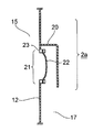
- FIG. 2 and 3 are enlarged longitudinal sectional views of the pressure relief device 2 (2a).
- FIG. 2 is an enlarged longitudinal sectional view of the pressure relief device 2a at a normal time before the abnormality occurs
- FIG. 3 is an enlarged longitudinal sectional view of the pressure relief device 2a at the time of abnormality.
- FIGS. 2 and 3 includes a protective cover 20, a flow path port 21, a rupturable plate 22, and a fastener 23. As shown in FIGS. 2 and 3, the pressure release device 2 a is attached to the sealed tank 12.
- the channel port 21 is formed so as to communicate the inside and the outside (atmosphere 17) of the sealed tank 12.
- the pressure release device 2 (2 a) When the pressure release operation is performed by the pressure release device 2 (2 a), the flow path port 21 becomes a discharge port through which the insulating gas 15 is released to the atmosphere 17.
- the rupturable plate 22 covers the flow path port 21 that connects the inside and the outside of the sealed tank 12 so as to be closed.
- the rupturable plate 22 is fixed and attached to the sealed tank 12 with a fastener 23.
- the rupturable plate 22 has a strength that is weaker than the pressure resistance (allowable pressure) of the insulating spacer 11 disposed in the target gas section 111 of the arc 14 and that bursts when abnormal.
- the normal time refers to the time when the pressure in the target gas section 111 for which the arc 14 is generated does not exceed the operating pressure of the pressure release device 2.
- the abnormal time refers to a time when the pressure in the target gas section 111 exceeds the operating pressure of the pressure release device 2.
- the operating pressure in the pressure relief device 2 a shown in FIG. 2 is a pressure exceeding the pressure resistance of the rupturable plate 22.
- the rupturable plate 22 holds the sealed tank 12 in a sealed state.
- the rupturable plate 22 bursts.
- the insulating gas 15 is discharged from the inside of the sealed tank 12 to the outside (atmosphere 17) through the flow path port 21, and the inside of the sealed tank 12 is released to near atmospheric pressure.
- the rupturable plate 22 of the pressure relief device 2 a is ruptured, and a channel having a minimum channel cross-sectional area SD is formed at the channel port 21.
- the insulating gas 15 passes through this flow path and is ejected in the arrow direction 191 from the inside to the outside of the sealed tank 12.
- the insulating gas 15 ejected in the arrow direction 191 changes the flow direction to the arrow direction 192 which is the open side of the protective cover 20 by the protective cover 20.
- the rupturable plate 22 can be exchanged. When the rupturable plate 22 is ruptured, a new rupturable plate 22 is attached to the fastener 23 and replaced.
- the desired arrow direction 192 is determined by conditions such as the installation environment and maintenance environment of the device, and the pressure release device 2 can change the mounting position and orientation of the protective cover 20 according to those conditions.
- the operating pressure Pop and the minimum flow path cross-sectional area SD of the pressure release device 2 are configured in a range defined by (Equation 1) shown below, while considering economy and safety.
- Equation 1 the pressure of the target gas section 111 of the sealed tank 12 can be suppressed to a pressure resistance PD or lower.
- the minimum channel cross-sectional area of the channel port 21 in the pressure release device 2 is SD
- SD is provided in the range of (Equation 1) shown below.
- Equation 1 the minimum channel cross-sectional area in the cross section is the minimum flow path cross-sectional area SD.
- the operating pressure at which the pressure release device 2 starts releasing pressure is set to Pop (Pa).
- the average effective value of the arc current as the estimated value is Ia (kA)
- the volume of the target gas section 111 is VT (m 3 ).
- the pressure resistance of the insulating spacer 11 is PD (Pa)
- the constant indicating the efficiency with which the arc energy contributes to the internal pressure increase is ⁇
- the first constant defining the pressure increase characteristic by the insulating gas 15 is Kga
- the insulating gas A second constant that defines the pressure release characteristic by 15 is Kgb
- Kc Kga ⁇ Ia ⁇ / VT.
- the minimum flow path cross-sectional area SD and the operating pressure Pop in the pressure release device 2 are determined within a range that satisfies the conditional expression of (Expression 1).
- FIG. 4 is a diagram showing a state of pressure change in the sealed tank 12 when an internal arc is generated.
- the horizontal axis indicates time
- the vertical axis indicates pressure
- the horizontal axis represents time
- the vertical axis represents current
- the current characteristics of the internal arc corresponding to the same time as the upper graph are shown.
- the insulating gas 15 is CO 2 gas, N 2 gas, etc.
- an internal arc (arc 14 shown in FIG. 1) is generated.
- the pressure in the sealed tank 12 increases.
- the pressure characteristic in this case is the waveform A shown in FIG. 4 and the current characteristic of the internal arc is the waveform D.
- a waveform B shown in FIG. 4 is shown for comparison with the waveform A, and an internal arc of the same energy is generated in the same volume sealed tank 12 shown in FIG. 1, and the insulating gas 15 is SF 6 gas. It is an example of pressure characteristics when the pressure release device 2 is not provided.
- waveform C shown in FIG. 4 is also shown for comparison with the waveform A.
- An internal arc of the same energy is generated in the same volume sealed tank 12 shown in FIG. and 2 gas, N 2 gas or the like, which is an example of a pressure profile in the case where not provided with a pressure relief device 2.
- These internal arcs have a common arc duration Ta as indicated by waveform D.
- 4 is the pressure resistance of the insulating spacer
- Pop is the operating pressure of the pressure release device 2
- Ps is the rated pressure of the closed tank 12 (corresponding to the sealing pressure in normal times)
- Pk is the atmospheric pressure.
- the pressure rise characteristic after the occurrence of the internal arc is as shown in the waveform B of FIG.
- the pressure release device 2 when the insulating gas 15 is CO 2 gas, N 2 gas, or the like, the pressure is higher than that of SF 6 gas, as shown by the waveform C in FIG. It is rising. That is, in these gases, the pressure in the closed tank 12 rises more steeply and to a higher pressure (maximum pressure PmaxC) than SF 6 gas. For this reason, in the electric power gas insulation apparatus of the subject mentioned above, there exists a possibility that the maximum pressure in the airtight tank 12 may exceed withstand pressure PD, and the environmental property of the apparatus, such as destroying the airtight tank 12, safety
- the pressure rise characteristic and the pressure release characteristic vary greatly depending on the type of insulating gas, the configuration of the equipment, and the state of the internal arc. Therefore, if the power gas insulation apparatus using SF 6 gas is applied simply when CO 2 gas, N 2 gas or the like is used, the above-described problems occur.
- the range of the operating pressure Pop and the minimum flow path cross-sectional area SD is appropriately determined so as to satisfy the condition of (Expression 1) described above, and an abnormality in the closed tank 12
- the pressure rise at the time can be suppressed so as not to exceed the pressure resistance PD. That is, as shown by the waveform A in FIG. 4, even if the pressure suddenly increases from the rated pressure Ps after the internal arc is generated, the maximum pressure PmaxA does not exceed the pressure resistance PD of the insulating spacer.
- the pressure of the target gas section 111 in the sealed tank 12 rises sharply at the same time as the occurrence of the internal arc, but the operating pressure When the pressure exceeds Pop, the pressure release device 2 operates, and the pressure in the target gas section 111 can be rapidly reduced and suppressed to the maximum pressure PmaxA that does not exceed the pressure resistance PD.
- the rupture disc 22 is ruptured when there is an abnormality in which the pressure of the target gas section 111 exceeds the operating pressure Pop.
- the target gas section 111 of the sealed tank 12 communicates with the atmosphere 17 via the minimum channel cross-sectional area SD at the channel port 21. Therefore, after the pressure release operation of the pressure release device 2a, as shown in the waveform A in FIG. 4, the internal arc in the target gas section 111 continues for the time Ta as shown in the waveform D in FIG. The speed of the pressure increase in the target gas section 111 is alleviated.
- the internal arc disappears, and the pressure of the target gas section 111 decreases to the vicinity of the atmospheric pressure Pk with time.
- the pressure of the target gas section 111 in the sealed tank 12 at the abnormal time in the gas gas insulation device according to the first embodiment becomes the pressure resistance PD. It can be avoided and safety is ensured.
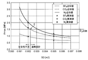
- FIG. 5 shows an example of the relationship between the minimum flow path cross-sectional area SD and the maximum pressure of the target gas section 111 in the pressure release device 2.
- the vertical axis is the maximum pressure Pmax (MPa)
- the horizontal axis is the minimum flow path cross-sectional area SD (m 2 )
- An example of an approximate value obtained by (Expression 2) and an actual measurement value for the relationship between Pmax and SD for each gas type is shown.
- SF 6 gas, CO 2 gas, for each for each fill gas type N 2 gas are shown together with curve obtained, the measured value in (Equation 2).
- the difference depending on the filling gas is defined by two constants of Kga and Kgb.
- Kga and Kgb are 14.2 and 600, respectively.
- CO 2 gas is the main component, they are 7.70 and 400, respectively.
- FIG. 5 it can be seen that the value obtained by (Equation 2) closely approximates the actual measurement value. In other words, the maximum pressure Pmax can be easily grasped by the simple expression shown in (Expression 2) even if the type of the filling gas is different.
- the minimum flow path cross-sectional area SD can be appropriately set within a range in which the maximum pressure Pmax in the sealed tank 12 does not exceed the pressure resistance PD.
- the design gas E is CO 2 gas and the pressure resistance PD is 1.5 (MPa).
- the minimum flow path cross-sectional area SD needs to be approximately 0.0022 (m 2 ) or more, and below that, the design is insufficient in safety.
- the overflow design greatly exceeds 0.0022 (m 2 ) with respect to the minimum flow path cross-sectional area SD, the structural cost for maintaining the hermeticity of the container is increased.
- the value of the minimum channel cross-sectional area SD may be set in consideration.
- the range of the minimum flow path cross-sectional area SD for ensuring safety is defined by (Expression 1), and (Expression 1) applies the condition of PD> Pmax in (Expression 2). Is derived.
- the operating pressure Pop at which the pressure release device 2 starts to be released can be determined based on the minimum flow path cross-sectional area SD.
- the minimum channel cross-sectional area SD can be determined based on the operating pressure Pop, or can be determined by adjusting these two values.
- the pressure release device 2 releases the closed tank 12 when the pressure in the gas section (target gas section 111) that is the target of arc generation exceeds the operating pressure Pop.
- the sealed tank 12 is sealed and held.
- the ejected gas is ejected in a safe direction by the protective cover 20, it is possible to avoid the high temperature / high pressure ejected gas from causing danger to the surroundings. Moreover, the safety
- SF 6 gas is not used as the insulating gas 15 and N 2 gas or CO 2 gas alone or N 2 gas or CO 2 gas is used as a main component in consideration of safety design.
- Gas including 50% or more in pressure ratio
- CO 2 gas recovered by some processing may be used as the insulating gas 15 filled in the sealed tank 12. In this case, it is excellent in environmental protection. By using these gases, it is possible to provide a power gas circuit breaker with excellent environmental performance.
- the pressure release device 2 safely releases the insulating gas 15 to the atmosphere 17 even when the pressure rise is abnormal. be able to.
- the sealed tank 12 is preferably not a tank manufactured by casting, but a tank processed by welding a rolled plate material. As a result, even in the case where an abnormal pressure is generated in the sealed tank 12 due to local heating due to an internal arc or an excessive increase in gas pressure in the sealed tank 12, the risk of the explosion of the entire tank is reduced. , Safety is further improved.
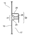
- FIG. 6 and 7 are enlarged longitudinal sectional views of the pressure release device 2b in the second embodiment.
- FIG. 6 is an enlarged longitudinal sectional view of the pressure relief device 2b in a normal state
- FIG. 7 is an enlarged longitudinal sectional view in an abnormal state.
- the second embodiment is different from the first embodiment in the following points.
- the basic configuration of a power gas insulation device (not shown) is the same as that of the first embodiment except for the pressure release device 2a in the first embodiment.
- the pressure relief device 2 b includes a protective cover 20, a flow path port 21, a valve body 24, and a spring 25. As shown in FIGS. 6 and 7, the pressure release device 2 b has a structure in which a spring 25 biases the valve body 24.
- the valve body 24 has a valve structure for closing and opening the flow path port 21 and is movable from the inside or the outside of the sealed tank 12.
- the valve body 24 is formed in a shape that closes the opening of the flow path port 21.
- 6 and 7 show an example of a structure in which the valve body 24 can close and open the flow passage port 21 from the outside of the sealed tank 12, but the valve body 24 flows from the inside of the sealed tank 12.
- close and open the roadway 21 may be sufficient.
- the spring 25 has one end attached to the valve body 24 and the other end fixed to the support member in order to bias the valve body 24.
- the protective cover 20 may be used as a support member, or a support member different from the protective cover 20 may be used.
- valve body 24 that is integrated with the spring 25 normally closes the flow path port 21 to seal the sealed tank 12, and when abnormal, opens the flow path port 21 to open the sealed tank 12. Release pressure.
- valve body when the pressure in the target gas section 111 of the closed tank 12 does not exceed the operating pressure Pop, the valve body is caused by the repulsive force of the spring 25 that urges the valve body 24 to close the flow path port 21. 24 closes the channel opening 21.
- the spring 25 that biases the valve body 24 is displaced toward the side of opening the flow path port 21, and the spring 25
- the valve body 24 opens the flow path port 21 in a state where the repulsive force and the pressure are balanced.
- a gap 211 is formed between the valve body 24 and the flow path port 21 outside the flow path port 21.
- the inner side and the outer side of the sealed tank 12 are communicated with each other through the gap 211, and the insulating gas 15 is released to the atmosphere 17. That is, the closed tank 12 is released by the pressure release device 2b.
- the minimum channel cross-sectional area in the gap 211 at the channel port 21 is SV (m 2 ).
- the minimum channel cross-sectional area SV is defined by an equation in which SD in the above-described (Equation 1) is replaced with SV.
- the minimum channel cross-sectional area SV of the gap 211 is a minimum cross-sectional area in a cross section perpendicular to the flowing direction of the insulating gas 15 at the channel port 21 (the arrow direction shown in FIG. 7).
- the insulating gas 15 is discharged from the inside of the sealed tank 12 to the outside through the gap 211.
- the protective cover 20 is attached to the sealed tank 12 in order to avoid the scattering of the ejected gas in a specific direction outside the flow path port 21.
- This protective cover 20 can change the ejection direction of a part of the ejection gas in the ejection direction.
- the operating pressure Pop can be adjusted in accordance with the elastic coefficient of the spring 25 of the pressure relief device 2b, as compared with the rupture plate 22 of the pressure relief device 2a in the first embodiment.
- the pressure in the closed tank 12 is reduced to the atmospheric pressure after the pressure release operation, but in the case of the second embodiment, the pressure in the closed tank 12 is kept at the initial filling pressure. Be drunk. For this reason, it is easy to ensure electrical insulation even after the pressure release operation.
- the minimum flow path cross-sectional area SV of the gap 211 formed during the pressure release operation is the pressure release in the first embodiment shown in FIG. It is difficult to ensure a larger value than the minimum channel cross-sectional area SD of the device 2a. Therefore, the second embodiment is suitable for applications where the average effective value Ia of the arc current, the arc firing time Ta, the tank volume VT of the gas section where the arc is generated, and the like are relatively small.
- the pressure release device 2b when the pressure in the target gas section 111 of the sealed tank 12 exceeds the operating pressure Pop when the pressure of the insulating gas 15 due to the internal arc is increased, the pressure release device 2b is released. Move to operation. That is, the pressure release device 2b shifts from a state in which the flow path port 21 is closed to an open state. Further, when the pressure of the target gas section 111 in the closed tank 12 exceeds the operating pressure Pop and falls below the pressure value, the valve body 24 changes from the state of opening the flow passage port 21 shown in FIG. 7 to the flow shown in FIG. Transition to a state in which the roadway 21 is closed. That is, the pressure release device 2b can switch between a state in which the flow path port 21 is opened and a state in which the flow path port 21 is closed according to the pressure of the target gas section 111 in the closed tank 12.
- the pressure increase due to an internal arc in the sealed tank 12 is caused.
- the pressure relief operation can be performed safely.
- burdens such as installation space and manufacturing cost can be reduced.
- the valve body and the spring are used for the pressure release device 2b, parts replacement is not necessary after the occurrence of an abnormality, so that maintenance costs and the like can be reduced.
- the power gas insulation device of the second embodiment it is possible to provide a power gas insulation device excellent in environmental performance, safety and economy.
- FIG. 8 is a longitudinal cross-sectional view of a power gas insulation apparatus according to the third embodiment.
- the basic configuration of the power gas insulation apparatus of the third embodiment shown in FIG. 8 is the same as that of the power gas insulation apparatus of the first and second embodiments, but there are differences in the following points.
- the gas section adjacent to the target gas section 111 is the adjacent gas section 112, and the insulating spacer 11a is disposed between the target gas section 111 and the adjacent gas section 112, and the pressure resistance is hermetically sealed.
- the strength is weaker than that of the tank 12 and the strength is such that it bursts when the operating pressure Pop of the pressure release device 2 is exceeded.
- the insulating spacer 11b is disposed between the adjacent gas section 112 and another adjacent gas section.
- the pressure resistance of the insulating spacer 11b is weaker than that of the sealed tank 12, and the strength of the insulating spacer 11b is stronger than the pressure resistance of the insulating spacer 11a. Is done.
- the inside of the closed tank 12 is defined as SD, where the minimum channel cross-sectional area in the cross section perpendicular to the outflow direction of the insulating gas 15 at the channel port 21 is SD, and the operating pressure at which the pressure release device 2 starts releasing pressure is Pop.
- the arc effective time of the arc current as an estimated value is Ta
- the ignition time of the arc as an estimated value is Ta
- the volume of the target gas section 111 is VT
- the adjacent gas adjacent to the target gas section 111 The volume Vn of the section 112, the pressure resistance of the insulating spacers 11b other than the insulating spacer 11a disposed in the target gas section 111 are PD
- the constant is ⁇ indicating the efficiency with which the arc energy contributes to the pressure increase
- the first constant that defines the pressure is Kga
- the second constant that defines the pressure relief characteristic by the insulating gas is Kgb
- Kc Kga ⁇ Ia ⁇ / (VT + Vn).
- SD and Pop in the pressure relief device 2 are SD> (VT + Vn) / ⁇ Kgb ⁇ log ((Kc ⁇ Ta ⁇ Pop) / (Kc ⁇ Ta ⁇ PD)) ⁇ (Formula 3) It is in the range that satisfies the conditional expression.
- the insulating spacer 11a arranged in the target gas section 111 of the closed tank 12 does not rupture at the normal time when the pressure in the target gas section 111 does not exceed the operating pressure Pop, and the pressure in the target gas section 111 does not exceed the operating pressure Pop. It bursts when it exceeds the abnormalities.
- the insulating spacer 11b since the insulating spacer 11b has a pressure resistance weaker than that of the sealed tank 12 and stronger than the pressure resistance of the insulating spacer 11a, it is abnormal unless the pressure value greatly exceeds the operating pressure Pop. Even at times, the insulating spacer 11b does not rupture.
- the insulation spacer 11a when an internal arc is generated and the pressure of the target gas section 111 exceeds the pressure resistance (allowable pressure) of the insulation spacer 11a, the insulation spacer 11a is fall into disrepair.
- the gas segment obtained by adding the target gas segment 111 and the adjacent gas segment 112 after the breakage becomes a new same target gas segment.
- the pressure release device 2 can perform a pressure release operation so that the pressure increase value does not exceed the pressure resistance PD. As a result, high-temperature and high-pressure gas is released to the atmosphere, but the volume (VT + Vn) of the gas section that is the target of effective arc generation of the sealed tank 12 is increased, so that the pressure increase during an abnormality is mitigated. The danger to the surroundings that destroys the sealed tank 12 can be reduced.
- an insulating spacer 11a may be disposed between the adjacent gas section 112 and another adjacent gas section adjacent to the adjacent gas section 112 instead of the insulating spacer 11b.
- the insulating spacer 11a arranged in this section is also damaged, in addition to the volume VT of the target gas section 111 and the volume Vn of the adjacent gas section 112, the total value obtained by adding the volumes of the other adjacent gas sections is This corresponds to the VT such as (Equation 1) described above.
- the volume corresponding to the VT of (Expression 1) can be effectively increased.
- the third embodiment is characterized in that a plurality of adjacent gas sections are provided by disposing the insulating spacer 11a or the insulating spacer 11b for each of a plurality of gas sections.
- the power gas insulation device of the third embodiment it is possible to provide a power gas insulation device excellent in environmental performance, safety and economy.
- the adjacent gas section 112 is not limited to a simple single-phase bus, but may be any device of a gas insulated switchgear such as a disconnect switch.
- the pressure relief device 2 can be omitted when the design is such that the minimum pressure cross-sectional area SD of the pressure relief device in (Equation 1) can be configured to be 0 or less.
- the power gas insulating device cannot include the pressure relief device 2.
- the pressure resistance of the insulating spacer 11a is determined as described in the third embodiment, and the pressure relief device 2 is not provided. Thereby, as described above, the volume of the effective gas section can be ensured when the internal arc is generated.
- SYMBOLS 1 Gas circuit breaker, 2, 2a, 2b ... Pressure release apparatus, 3 ... High voltage conductor, 11, 11a, 11b ... Insulating spacer, 12 ... Sealed tank, 14 ... Arc, 15 ... Insulating gas, 17 ... Air
Landscapes
- Engineering & Computer Science (AREA)
- Power Engineering (AREA)
- Microelectronics & Electronic Packaging (AREA)
- Gas-Insulated Switchgears (AREA)
- Driving Mechanisms And Operating Circuits Of Arc-Extinguishing High-Tension Switches (AREA)
- High-Tension Arc-Extinguishing Switches Without Spraying Means (AREA)
Abstract
Description
図1は本発明に係る電力用ガス絶縁機器の第1の実施形態を示す縦断面図である。
SD>VT/Kgb/log((Kc×Ta-Pop)/(Kc×Ta-PD)) ・・・(式1)
(式1)の条件式を満足する範囲に、放圧装置2における最小流路断面積SDおよび作動圧力Popが定められる。
Pmax=Pop+(Kc×Ta-Pop)×{1-e-(VT/Kgb/SD)} ・・・(式2)
なお、(式2)の式中の各変数、およびその単位については、(式1)で記載したものと同一である。以下に、(式2)の経験式としての妥当性を示す。
図6および図7は第2の実施形態における放圧装置2bの拡大縦断面図である。特に、図6は通常時の放圧装置2bにおける拡大縦断面図、同様に、図7は異常時の拡大縦断面図である。第2の実施形態は、第1の実施形態と以下の点に相違がある。
図8は第3の実施形態における電力用ガス絶縁機器の縦断面図である。図8に示す第3の実施形態の電力用ガス絶縁機器の基本的な構成は、第1および第2の実施形態の電力用ガス絶縁機器と同じであるが、下記の点に相違がある。
SD>(VT+Vn)/{Kgb×log((Kc×Ta-Pop)/(Kc×Ta-PD))} (式3)
の条件式を満足する範囲にある。
第3の実施形態における変形の実施形態として、(式1)における放圧装置の最小流路断面積SDが0以下でも構成可能な設計である場合に、放圧装置2を具備しないことができる。例えば、絶縁ガスを大気へ放出できない制約、規制等がある場合に、電力用ガス絶縁機器が放圧装置2を具備することができない。このような場合には、第3の実施形態における変形の実施形態として、絶縁スペーサ11aの耐圧力を第3の実施形態に述べたように定めて、かつ、放圧装置2を具備しない。これにより、前述したように、内部アーク発生時に、実効的なガス区分の容積を確保することができる。
Claims (8)
- 課電される高電圧導体と、
絶縁ガスが充填される密閉容器と、
前記密閉容器を複数のガス区分に区画するとともに、前記高電圧導体と前記密閉容器との間の絶縁を保持しながら前記高電圧導体を支持する絶縁スペーサと、
前記密閉容器の内側と外側へ連通された流路口が設けられ、当該流路口を閉じることにより前記密閉容器を密封し、当該流路口を開くことにより前記密閉容器を放圧する放圧装置と、
を具備する電力用ガス絶縁機器において、
前記流路口での前記絶縁ガスの流出方向に対して垂直の断面における最小流路断面積をSDとし、前記放圧装置が放圧を開始する作動圧力をPopとして、前記密閉容器の内側で発生するアークについて、推定値としたアーク電流の平均実効値をIa、推定値としたアークの点弧時間をTa、前記アークの発生対象とするガス区分の容積をVT、前記絶縁スペーサの耐圧力をPD、前記アークのエネルギが圧力上昇に寄与する効率を示す定数をα、前記絶縁ガスによる圧力上昇特性を規定する第1の定数をKga、前記絶縁ガスによる放圧特性を規定する第2の定数をKgbとし、Kc=Kga×Iaα/VTとする場合に、
SD>VT/{Kgb×log((Kc×Ta-Pop)/(Kc×Ta-PD))}
の条件式を満足する範囲にあり、
前記放圧装置は、前記アークの発生対象とするガス区分における圧力が前記作動圧力を超えない通常時に前記密閉容器を密封して保持し、前記アークの発生対象とするガス区分における圧力が前記作動圧力を超えた異常時に前記密閉容器を放圧する
ことを特徴とする電力用ガス絶縁機器。 - 前記放圧装置は、前記密閉容器の前記流路口を閉じるように覆う破裂板を有し、
前記破裂板は、前記アークの発生対象とするガス区分に配置される前記絶縁スペーサの耐圧力より弱くされ、かつ、前記異常時に破裂する強度である
ことを特徴とする請求項1に記載の電力用ガス絶縁機器。 - 前記放圧装置は、前記流路口を閉じる弁体と、前記流路口を閉じる側に前記弁体を付勢する弾性体とを有し、
前記通常時に前記弾性体の付勢力により前記弁体が前記流路口を閉鎖しており、前記異常時に前記弾性体が縮んで、前記弁体が前記流路口を開く位置まで移動する
ことを特徴とする請求項1に記載の電力用ガス絶縁機器。 - 前記放圧装置は、前記密閉容器が放圧された場合における前記絶縁ガスの噴出方向を変えるために前記密閉容器の外側に設けられた保護カバーを有する
ことを特徴とする請求項1ないし請求項3のいずれか一項に記載の電力用ガス絶縁機器。 - 前記複数のガス区分に区画する絶縁スペーサの中で、少なくとも、前記密閉容器の内側でアークの発生対象とするガス区分に配置される絶縁スペーサは、前記密閉容器の耐圧力より弱くされ、かつ、前記密閉容器の内側でアークの発生対象とするガス区分に配置される絶縁スペーサにおける前記絶縁ガスの流出方向に対して垂直の断面における最小流路断面積をSDbとし、前記アークの発生対象とするガス区分に配置される絶縁スペーサ以外の絶縁スペーサの耐圧力をPDbとし、前記アークの発生対象とするガス区分と隣接するガス区分の体積をVnとし、Kcb=Kga×Iaα/(VT+Vn)とする場合に、
SDb>(VT+Vn)/{Kgb×log((Kcb×Ta-Pop)/(Kcb×Ta-PDb))}
の条件式を満足する範囲にあり、前記アークの発生対象とするガス区分における圧力が前記作動圧力を超えない通常時には破裂せず、前記アークの発生対象とするガス区分における圧力が前記作動圧力を超えた異常時には破裂する
ことを特徴とする請求項1ないし請求項4のいずれか一項に記載の電力用ガス絶縁機器。 - 課電される高電圧導体と、
絶縁ガスが充填される密閉容器と、
前記密閉容器を複数のガス区分に区画するとともに、前記高電圧導体と前記密閉容器との間の絶縁を保持しながら前記高電圧導体を支持する絶縁スペーサと、
前記密閉容器の内側と外側へ連通された流路口が設けられ、当該流路口を閉じることにより前記密閉容器を密封し、当該流路口を開くことにより前記密閉容器を放圧する放圧装置と、
を具備する電力用ガス絶縁機器において、
前記複数のガス区分に区画する絶縁スペーサの中で、少なくとも、前記密閉容器の内側でアークの発生対象とするガス区分に配置される絶縁スペーサは、前記密閉容器の耐圧力より弱くされ、かつ、前記流路口での前記絶縁ガスの流出方向に対して垂直の断面における最小流路断面積をSDとし、前記放圧装置が放圧を開始する作動圧力をPopとして、前記密閉容器の内側で発生するアークについて、推定値としたアーク電流の平均実効値をIa、推定値としたアークの点弧時間をTa、前記アークの発生対象とするガス区分の容積をVT、前記アークの発生対象とするガス区分と隣接するガス区分の体積Vn、前記アークの発生対象とするガス区分に配置される絶縁スペーサ以外の絶縁スペーサの耐圧力をPD、前記アークのエネルギが圧力上昇に寄与する効率を示す定数をα、前記絶縁ガスによる圧力上昇特性を規定する第1の定数をKga、前記絶縁ガスによる放圧特性を規定する第2の定数をKgbとし、Kc=Kga×Iaα/(VT+Vn)とする場合に、
SD>(VT+Vn)/{Kgb×log((Kc×Ta-Pop)/(Kc×Ta-PD))}
の条件式を満足する範囲にあり、前記アークの発生対象とするガス区分における圧力が前記作動圧力を超えない通常時には破裂せず、前記アークの発生対象とするガス区分における圧力が前記作動圧力を超えた異常時には破裂する
ことを特徴とする電力用ガス絶縁機器。 - 前記絶縁ガスは、N2ガス、CO2ガス、N2ガスを主成分として含む混合ガス、CO2ガスを主成分として含む混合ガスのいずれかである
ことを特徴とする請求項1ないし請求項6のいずれか一項に記載の電力用ガス絶縁機器。 - 前記密閉容器は、圧延された板材を溶接して形成されたタンクである
ことを特徴とする請求項1ないし請求項7のいずれか一項に記載の電力用ガス絶縁機器。
Priority Applications (5)
| Application Number | Priority Date | Filing Date | Title |
|---|---|---|---|
| KR1020127030371A KR101413344B1 (ko) | 2011-11-22 | 2012-09-06 | 전력용 가스 절연 기기 |
| BR112014012260A BR112014012260A2 (pt) | 2011-11-22 | 2012-09-06 | equipamento elétrico com isolamento de gás |
| EP12850866.0A EP2784886B1 (en) | 2011-11-22 | 2012-09-06 | Gas-insulated device for electrical use |
| CN201280001407.5A CN103229374B (zh) | 2011-11-22 | 2012-09-06 | 电力用气体绝缘设备 |
| US14/276,677 US9258917B2 (en) | 2011-11-22 | 2014-05-13 | Gas insulated electrical equipment |
Applications Claiming Priority (2)
| Application Number | Priority Date | Filing Date | Title |
|---|---|---|---|
| JP2011-255049 | 2011-11-22 | ||
| JP2011255049A JP5872260B2 (ja) | 2011-11-22 | 2011-11-22 | 電力用ガス絶縁機器およびその製造方法 |
Related Child Applications (1)
| Application Number | Title | Priority Date | Filing Date |
|---|---|---|---|
| US14/276,677 Continuation-In-Part US9258917B2 (en) | 2011-11-22 | 2014-05-13 | Gas insulated electrical equipment |
Publications (1)
| Publication Number | Publication Date |
|---|---|
| WO2013076892A1 true WO2013076892A1 (ja) | 2013-05-30 |
Family
ID=48469364
Family Applications (1)
| Application Number | Title | Priority Date | Filing Date |
|---|---|---|---|
| PCT/JP2012/005650 WO2013076892A1 (ja) | 2011-11-22 | 2012-09-06 | 電力用ガス絶縁機器 |
Country Status (7)
| Country | Link |
|---|---|
| US (1) | US9258917B2 (ja) |
| EP (1) | EP2784886B1 (ja) |
| JP (1) | JP5872260B2 (ja) |
| KR (1) | KR101413344B1 (ja) |
| CN (1) | CN103229374B (ja) |
| BR (1) | BR112014012260A2 (ja) |
| WO (1) | WO2013076892A1 (ja) |
Cited By (1)
| Publication number | Priority date | Publication date | Assignee | Title |
|---|---|---|---|---|
| US10582647B2 (en) | 2014-02-19 | 2020-03-03 | Tetra Laval Holdings & Finance S.A. | Power supply unit |
Families Citing this family (6)
| Publication number | Priority date | Publication date | Assignee | Title |
|---|---|---|---|---|
| KR200484705Y1 (ko) * | 2013-07-02 | 2017-10-18 | 엘에스산전 주식회사 | 배출 수단을 갖는 가스절연개폐장치 |
| JP2015056380A (ja) * | 2013-09-13 | 2015-03-23 | 株式会社豊田自動織機 | 電流遮断装置及びそれを用いた蓄電装置 |
| JP6457365B2 (ja) * | 2015-09-14 | 2019-01-23 | 株式会社東芝 | 圧力容器 |
| KR200486519Y1 (ko) * | 2016-08-16 | 2018-05-31 | 주식회사 서흥이엔지 | 자동개폐기용 밸브 |
| GB2585026B (en) | 2019-06-25 | 2023-03-29 | Bae Systems Plc | Overpressure protection system for a magazine |
| KR102397195B1 (ko) * | 2020-06-30 | 2022-05-12 | 한국전력공사 | 가스절연 개폐기의 방압 장치 |
Citations (5)
| Publication number | Priority date | Publication date | Assignee | Title |
|---|---|---|---|---|
| JPH027817A (ja) * | 1988-06-15 | 1990-01-11 | Fuji Electric Co Ltd | ガス絶縁開閉装置のガス封入容器 |
| JPH04133606A (ja) * | 1990-09-25 | 1992-05-07 | Fuji Electric Co Ltd | キュービクル形ガス絶縁開閉装置 |
| JPH09275609A (ja) * | 1996-04-01 | 1997-10-21 | Mitsubishi Electric Corp | ガス封入容器の放圧ダクト |
| JP2003142318A (ja) | 2001-11-01 | 2003-05-16 | Hitachi Ltd | ガス絶縁変圧器 |
| JP2007258137A (ja) | 2006-03-27 | 2007-10-04 | Toshiba Corp | ガス絶縁開閉器 |
Family Cites Families (12)
| Publication number | Priority date | Publication date | Assignee | Title |
|---|---|---|---|---|
| FR2121074A5 (ja) * | 1970-12-29 | 1972-08-18 | Fuji Electric Co Ltd | |
| DE2739030C3 (de) * | 1977-08-26 | 1981-08-13 | Siemens AG, 1000 Berlin und 8000 München | Druckentlastungseinrichtung für eine metallgekapselte, gasisolierte Hochspannungsanlage |
| DE3438635A1 (de) * | 1984-09-26 | 1986-04-03 | BBC Aktiengesellschaft Brown, Boveri & Cie., Baden, Aargau | Druckgasschalter |
| FR2661776B1 (fr) * | 1990-05-04 | 1996-05-10 | Merlin Gerin | Declencheur instantane d'un disjoncteur. |
| JP2997027B2 (ja) * | 1990-09-17 | 2000-01-11 | 株式会社日立製作所 | ガス絶縁電気機器 |
| US5761025A (en) * | 1995-02-13 | 1998-06-02 | Iversen; Arthur H. | Low cost power switchgear |
| JP3008175B2 (ja) * | 1996-04-12 | 2000-02-14 | 水道機工株式会社 | 重力式濾過装置 |
| FR2808118B1 (fr) * | 2000-04-19 | 2004-06-18 | Alstom | Interrupteur a auto-soufflage avec une chambre de coupure a deux volumes |
| FR2868197B1 (fr) * | 2004-03-25 | 2006-05-19 | Areva T & D Sa | Dispositif de commande pour l'actionnement coordonne d'au moins deux appareils de commutation dont un est a coupure dans le vide |
| EP1863054B1 (en) * | 2006-05-29 | 2010-01-27 | ABB Technology AG | A puffer circuit breaker with an overpressure valve |
| JP5127569B2 (ja) | 2008-05-29 | 2013-01-23 | 株式会社東芝 | ガス絶縁開閉器 |
| FR2944134B1 (fr) * | 2009-04-03 | 2014-08-29 | Schneider Electric Ind Sas | Enveloppe isolante sous pression d'un appareil de protection electrique |
-
2011
- 2011-11-22 JP JP2011255049A patent/JP5872260B2/ja active Active
-
2012
- 2012-09-06 WO PCT/JP2012/005650 patent/WO2013076892A1/ja active Application Filing
- 2012-09-06 BR BR112014012260A patent/BR112014012260A2/pt not_active Application Discontinuation
- 2012-09-06 EP EP12850866.0A patent/EP2784886B1/en active Active
- 2012-09-06 KR KR1020127030371A patent/KR101413344B1/ko active IP Right Grant
- 2012-09-06 CN CN201280001407.5A patent/CN103229374B/zh active Active
-
2014
- 2014-05-13 US US14/276,677 patent/US9258917B2/en active Active
Patent Citations (5)
| Publication number | Priority date | Publication date | Assignee | Title |
|---|---|---|---|---|
| JPH027817A (ja) * | 1988-06-15 | 1990-01-11 | Fuji Electric Co Ltd | ガス絶縁開閉装置のガス封入容器 |
| JPH04133606A (ja) * | 1990-09-25 | 1992-05-07 | Fuji Electric Co Ltd | キュービクル形ガス絶縁開閉装置 |
| JPH09275609A (ja) * | 1996-04-01 | 1997-10-21 | Mitsubishi Electric Corp | ガス封入容器の放圧ダクト |
| JP2003142318A (ja) | 2001-11-01 | 2003-05-16 | Hitachi Ltd | ガス絶縁変圧器 |
| JP2007258137A (ja) | 2006-03-27 | 2007-10-04 | Toshiba Corp | ガス絶縁開閉器 |
Non-Patent Citations (2)
| Title |
|---|
| "The Load on the Earth's Environment of SF6 and Insulation by SF6 Mixture/Substitute Gases", TECHNICAL REPORT OF THE INSTITUTE OF ELECTRICAL ENGINEERS OF JAPAN, 2001 |
| See also references of EP2784886A4 * |
Cited By (1)
| Publication number | Priority date | Publication date | Assignee | Title |
|---|---|---|---|---|
| US10582647B2 (en) | 2014-02-19 | 2020-03-03 | Tetra Laval Holdings & Finance S.A. | Power supply unit |
Also Published As
| Publication number | Publication date |
|---|---|
| EP2784886A1 (en) | 2014-10-01 |
| BR112014012260A2 (pt) | 2017-06-13 |
| US9258917B2 (en) | 2016-02-09 |
| EP2784886B1 (en) | 2017-05-24 |
| CN103229374A (zh) | 2013-07-31 |
| EP2784886A4 (en) | 2015-08-12 |
| KR20130070603A (ko) | 2013-06-27 |
| JP2013110883A (ja) | 2013-06-06 |
| CN103229374B (zh) | 2015-09-02 |
| KR101413344B1 (ko) | 2014-06-27 |
| US20140247538A1 (en) | 2014-09-04 |
| JP5872260B2 (ja) | 2016-03-01 |
Similar Documents
| Publication | Publication Date | Title |
|---|---|---|
| JP5872260B2 (ja) | 電力用ガス絶縁機器およびその製造方法 | |
| WO2017094449A1 (ja) | ガス絶縁開閉装置 | |
| RU2458425C2 (ru) | Высоковольтный выключатель с функцией разъединителя и способ управления выключателем | |
| CN211046231U (zh) | 一种气体绝缘封闭式开关柜 | |
| US11145476B2 (en) | Electric high-voltage circuit breaker | |
| KR20090059818A (ko) | 가스차단기의 고온 가스 배출장치 | |
| US20200287372A1 (en) | Method and device for permanent disconnection of an electrical circuit with an inductive load by switching two switches | |
| EP3570393B1 (en) | Switchgear | |
| EP3961668B1 (en) | Shut-off switch for gas insulated switchgear | |
| KR101386134B1 (ko) | 열팽창실 압력 조절형 복합 소호 가스차단기 | |
| US9018558B2 (en) | Gas circuit breaker | |
| KR20120131266A (ko) | 가스절연 개폐장치의 방압변 커버 | |
| CN204303602U (zh) | 快速灭弧装置 | |
| WO2020208737A1 (ja) | 放圧装置及びガス絶縁開閉装置 | |
| KR102108817B1 (ko) | 조작용이성과 절연가스 역류방지 기능을 갖춘 gis용 차단기 | |
| CN107968348B (zh) | 气体绝缘开关柜 | |
| CN113488896B (zh) | 一种抽出式开关柜 | |
| EP3531518A1 (en) | Exhaust gas duct for gas-insulated switchgear and gas-insulated switchgear having an exhaust gas duct | |
| CN201898077U (zh) | 一种高压负荷开关壳体下盖 | |
| JP2012033363A (ja) | 碍子型開閉装置 | |
| JP2021125886A (ja) | ガス絶縁開閉装置 | |
| CN207572836U (zh) | 气体绝缘开关柜 | |
| EP3840005A1 (en) | Two way piston interrupter | |
| JP2023113451A (ja) | 発電機用遮断器 | |
| KR20150009761A (ko) | 열팽창실의 이중압축 구조를 구비하는 가스절연개폐장치의 차단기 |
Legal Events
| Date | Code | Title | Description |
|---|---|---|---|
| ENP | Entry into the national phase |
Ref document number: 20127030371 Country of ref document: KR Kind code of ref document: A |
|
| 121 | Ep: the epo has been informed by wipo that ep was designated in this application |
Ref document number: 12850866 Country of ref document: EP Kind code of ref document: A1 |
|
| NENP | Non-entry into the national phase |
Ref country code: DE |
|
| REEP | Request for entry into the european phase |
Ref document number: 2012850866 Country of ref document: EP |
|
| WWE | Wipo information: entry into national phase |
Ref document number: 2012850866 Country of ref document: EP |
|
| REG | Reference to national code |
Ref country code: BR Ref legal event code: B01A Ref document number: 112014012260 Country of ref document: BR |
|
| ENPW | Started to enter national phase and was withdrawn or failed for other reasons |
Ref document number: 112014012260 Country of ref document: BR |
|
| ENPZ | Former announcement of the withdrawal of the entry into the national phase was wrong |
Ref document number: 112014012260 Country of ref document: BR Kind code of ref document: A2 |
|
| ENP | Entry into the national phase |
Ref document number: 112014012260 Country of ref document: BR Kind code of ref document: A2 Effective date: 20140521 |