WO2013076825A1 - Oil pressure control device - Google Patents
Oil pressure control device Download PDFInfo
- Publication number
- WO2013076825A1 WO2013076825A1 PCT/JP2011/076951 JP2011076951W WO2013076825A1 WO 2013076825 A1 WO2013076825 A1 WO 2013076825A1 JP 2011076951 W JP2011076951 W JP 2011076951W WO 2013076825 A1 WO2013076825 A1 WO 2013076825A1
- Authority
- WO
- WIPO (PCT)
- Prior art keywords
- oil
- accumulator
- pressure
- clutch
- hydraulic
- Prior art date
Links
Images


Classifications
-
- F—MECHANICAL ENGINEERING; LIGHTING; HEATING; WEAPONS; BLASTING
- F16—ENGINEERING ELEMENTS AND UNITS; GENERAL MEASURES FOR PRODUCING AND MAINTAINING EFFECTIVE FUNCTIONING OF MACHINES OR INSTALLATIONS; THERMAL INSULATION IN GENERAL
- F16H—GEARING
- F16H61/00—Control functions within control units of change-speed- or reversing-gearings for conveying rotary motion ; Control of exclusively fluid gearing, friction gearing, gearings with endless flexible members or other particular types of gearing
- F16H61/0021—Generation or control of line pressure
-
- F—MECHANICAL ENGINEERING; LIGHTING; HEATING; WEAPONS; BLASTING
- F16—ENGINEERING ELEMENTS AND UNITS; GENERAL MEASURES FOR PRODUCING AND MAINTAINING EFFECTIVE FUNCTIONING OF MACHINES OR INSTALLATIONS; THERMAL INSULATION IN GENERAL
- F16H—GEARING
- F16H61/00—Control functions within control units of change-speed- or reversing-gearings for conveying rotary motion ; Control of exclusively fluid gearing, friction gearing, gearings with endless flexible members or other particular types of gearing
- F16H61/0003—Arrangement or mounting of elements of the control apparatus, e.g. valve assemblies or snapfittings of valves; Arrangements of the control unit on or in the transmission gearbox
-
- B—PERFORMING OPERATIONS; TRANSPORTING
- B60—VEHICLES IN GENERAL
- B60W—CONJOINT CONTROL OF VEHICLE SUB-UNITS OF DIFFERENT TYPE OR DIFFERENT FUNCTION; CONTROL SYSTEMS SPECIALLY ADAPTED FOR HYBRID VEHICLES; ROAD VEHICLE DRIVE CONTROL SYSTEMS FOR PURPOSES NOT RELATED TO THE CONTROL OF A PARTICULAR SUB-UNIT
- B60W10/00—Conjoint control of vehicle sub-units of different type or different function
- B60W10/02—Conjoint control of vehicle sub-units of different type or different function including control of driveline clutches
-
- B—PERFORMING OPERATIONS; TRANSPORTING
- B60—VEHICLES IN GENERAL
- B60W—CONJOINT CONTROL OF VEHICLE SUB-UNITS OF DIFFERENT TYPE OR DIFFERENT FUNCTION; CONTROL SYSTEMS SPECIALLY ADAPTED FOR HYBRID VEHICLES; ROAD VEHICLE DRIVE CONTROL SYSTEMS FOR PURPOSES NOT RELATED TO THE CONTROL OF A PARTICULAR SUB-UNIT
- B60W10/00—Conjoint control of vehicle sub-units of different type or different function
- B60W10/04—Conjoint control of vehicle sub-units of different type or different function including control of propulsion units
- B60W10/06—Conjoint control of vehicle sub-units of different type or different function including control of propulsion units including control of combustion engines
-
- F—MECHANICAL ENGINEERING; LIGHTING; HEATING; WEAPONS; BLASTING
- F16—ENGINEERING ELEMENTS AND UNITS; GENERAL MEASURES FOR PRODUCING AND MAINTAINING EFFECTIVE FUNCTIONING OF MACHINES OR INSTALLATIONS; THERMAL INSULATION IN GENERAL
- F16H—GEARING
- F16H61/00—Control functions within control units of change-speed- or reversing-gearings for conveying rotary motion ; Control of exclusively fluid gearing, friction gearing, gearings with endless flexible members or other particular types of gearing
- F16H61/0021—Generation or control of line pressure
- F16H61/0025—Supply of control fluid; Pumps therefore
-
- F—MECHANICAL ENGINEERING; LIGHTING; HEATING; WEAPONS; BLASTING
- F16—ENGINEERING ELEMENTS AND UNITS; GENERAL MEASURES FOR PRODUCING AND MAINTAINING EFFECTIVE FUNCTIONING OF MACHINES OR INSTALLATIONS; THERMAL INSULATION IN GENERAL
- F16H—GEARING
- F16H61/00—Control functions within control units of change-speed- or reversing-gearings for conveying rotary motion ; Control of exclusively fluid gearing, friction gearing, gearings with endless flexible members or other particular types of gearing
- F16H61/02—Control functions within control units of change-speed- or reversing-gearings for conveying rotary motion ; Control of exclusively fluid gearing, friction gearing, gearings with endless flexible members or other particular types of gearing characterised by the signals used
- F16H61/0262—Control functions within control units of change-speed- or reversing-gearings for conveying rotary motion ; Control of exclusively fluid gearing, friction gearing, gearings with endless flexible members or other particular types of gearing characterised by the signals used the signals being hydraulic
- F16H61/0265—Control functions within control units of change-speed- or reversing-gearings for conveying rotary motion ; Control of exclusively fluid gearing, friction gearing, gearings with endless flexible members or other particular types of gearing characterised by the signals used the signals being hydraulic for gearshift control, e.g. control functions for performing shifting or generation of shift signals
- F16H61/0267—Layout of hydraulic control circuits, e.g. arrangement of valves
-
- F—MECHANICAL ENGINEERING; LIGHTING; HEATING; WEAPONS; BLASTING
- F16—ENGINEERING ELEMENTS AND UNITS; GENERAL MEASURES FOR PRODUCING AND MAINTAINING EFFECTIVE FUNCTIONING OF MACHINES OR INSTALLATIONS; THERMAL INSULATION IN GENERAL
- F16H—GEARING
- F16H61/00—Control functions within control units of change-speed- or reversing-gearings for conveying rotary motion ; Control of exclusively fluid gearing, friction gearing, gearings with endless flexible members or other particular types of gearing
- F16H61/0021—Generation or control of line pressure
- F16H2061/0034—Accumulators for fluid pressure supply; Control thereof
Definitions
- the present invention relates to a hydraulic control device.
- Patent Document 1 discloses a first accumulator for supplying hydraulic pressure to the clutch drive system when the engine is restarted when returning from idling stop control, and a second accumulator for reducing clutch engagement shock.
- a configuration including an accumulator is disclosed.
- the configuration including two accumulators for supplying hydraulic pressure at the time of engine restart and reducing the engagement shock increases the number of parts and makes the configuration complicated.
- the present invention has been made in view of the above, and provides a hydraulic control device capable of realizing both the supply of hydraulic pressure to a clutch at the time of engine restart and the reduction of clutch engagement shock with a simple configuration. For the purpose.
- a hydraulic control apparatus includes a mechanical pump that discharges oil by driving an engine, a hydraulic path that supplies oil discharged by the mechanical pump to a clutch, A clutch pressure control valve for controlling a clutch pressure, which is a hydraulic pressure supplied to the clutch, and a hydraulic pressure to the clutch in response to a shift operation of the vehicle, provided downstream of the clutch pressure control valve in the hydraulic path.
- An accumulator that accumulates oil supplied by the mechanical pump, discharges the accumulated oil, and supplies the accumulated oil to the clutch, and a clutch pressure control valve.
- a first oil path connected to the hydraulic path on the upstream side, and the hydraulic path on the downstream side of the manual valve.
- a connection control means for controlling connection between the accumulator and the hydraulic path so as to communicate the accumulator with one of the first oil path and the second oil path. It is characterized by.
- connection control unit communicates the accumulator with the hydraulic path via the first oil path when the engine is stopped, and via the second oil path when the engine is operating. It is preferable to include a switching valve that switches the accumulator so as to communicate with the hydraulic path, and a pressure accumulation control valve that is disposed between the switching valve and the accumulator and controls pressure accumulation and discharge of the accumulator.
- a single accumulator is connected to the hydraulic path via either the first oil path or the second oil path, and a single accumulator is used to supply hydraulic pressure to the clutch when the engine is restarted.
- accumulation / discharge function accumulation / discharge function
- a function for reducing clutch engagement shock reducing clutch engagement shock
- FIG. 1 is a schematic diagram showing the configuration of a vehicle equipped with a hydraulic control device according to an embodiment of the present invention.
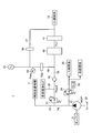
- FIG. 2 is a diagram showing a schematic configuration of the hydraulic control apparatus in FIG.
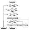
- FIG. 3 is a flowchart showing the accumulator pressure accumulation process performed by the hydraulic control apparatus of the present embodiment.
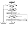
- FIG. 4 is a flowchart showing an accumulator discharge process performed by the hydraulic control apparatus of the present embodiment.
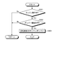
- FIG. 5 is a flowchart showing a process of using the accumulator as a damper, which is performed by the hydraulic control apparatus of the present embodiment.
- FIG. 6 is a diagram illustrating a modification of the hydraulic control device according to the present embodiment.
- the vehicle 2 which mounts the hydraulic control apparatus 1 which concerns on this embodiment is demonstrated.
- the vehicle 2 includes an engine 3 as a power source during traveling, a drive wheel 4, a power transmission device 5, a hydraulic control device 1, and an ECU (Electronic Control Unit: electronic control unit). 7.
- the engine 3 is a driving source (prime mover) for driving the vehicle 2, and generates power that consumes fuel and acts on the driving wheels 4 of the vehicle 2.
- the engine 3 can generate mechanical power (engine torque) on the crankshaft 8 that is an engine output shaft as the fuel burns, and can output this mechanical power from the crankshaft 8 toward the drive wheels 4. .
- the power transmission device 5 transmits power from the engine 3 to the drive wheels 4.
- the power transmission device 5 is provided in a power transmission path from the engine 3 to the drive wheel 4 and is operated by the pressure (hydraulic pressure) of oil as a liquid medium.
- the power transmission device 5 includes a torque converter 9, a forward / reverse switching mechanism 10, a continuously variable transmission mechanism 11, a speed reduction mechanism 12, a differential gear 13, and the like.
- the crankshaft 8 of the engine 3 and the input shaft 14 of the continuously variable transmission mechanism 11 are connected via a torque converter 9, a forward / reverse switching mechanism 10, and the like, and an output shaft 15 of the continuously variable transmission mechanism 11 is connected. It is connected to the drive wheel 4 via the speed reduction mechanism 12, the differential gear 13, the drive shaft 16, and the like.
- the torque converter 9 is disposed between the engine 3 and the forward / reverse switching mechanism 10, and amplifies (or maintains) the power torque transmitted from the engine 3 and transmits it to the forward / reverse switching mechanism 10. It can.
- the torque converter 9 includes a pump impeller 9a and a turbine runner 9b that are rotatably arranged to face each other, and the pump impeller 9a is coupled to the crankshaft 8 through a front cover 9c so as to be integrally rotatable, and the turbine runner 9b is switched forward and backward. It is configured to be connected to the mechanism 10. As the pump impeller 9a and the turbine runner 9b rotate, a viscous fluid such as hydraulic fluid interposed between the pump impeller 9a and the turbine runner 9b circulates and flows. It is possible to amplify and transmit torque while allowing
- the torque converter 9 further includes a lock-up clutch 9d that is provided between the turbine runner 9b and the front cover 9c and is coupled to the turbine runner 9b so as to be integrally rotatable.
- the lock-up clutch 9d is operated by oil pressure supplied from a hydraulic control device 1 described later, and is switched between an engaged state (lock-up ON) and a released state (lock-up OFF) with the front cover 9c.
- the torque converter 9 transmits the torque transmitted from the engine 3 to the forward / reverse switching mechanism 10 as it is.
- the forward / reverse switching mechanism 10 can shift the power (rotational output) from the engine 3 and can switch the rotation direction.
- the forward / reverse switching mechanism 10 includes a planetary gear mechanism 17, a forward / reverse switching clutch (forward clutch) C1 as a friction engagement element, a forward / reverse switching brake (reverse brake) B1, and the like.
- the planetary gear mechanism 17 is a differential mechanism that includes a sun gear, a ring gear, a carrier, and the like as a plurality of rotational elements that can rotate differentially with each other.
- the forward / reverse switching clutch C1 and the forward / reverse switching brake B1 It is an engagement element for switching the operating state of the gear mechanism 17 and can be constituted by, for example, a frictional engagement mechanism such as a multi-plate clutch.
- a hydraulic wet multi-plate clutch is used.
- the forward / reverse switching clutch C1 and the forward / reverse switching brake B1 are operated by the pressure of oil supplied from the hydraulic control device 1 described later, and the operating state is switched.
- the forward / reverse switching clutch C1 is in the engaged state (ON state) and the forward / reverse switching brake B1 is in the released state (OFF state)
- the forward / reverse switching mechanism 10 rotates the power from the engine 3 in the normal rotation (vehicle 2). Is transmitted to the input shaft 14 in the direction in which the input shaft 14 rotates as the vehicle advances.
- the forward / reverse switching mechanism 10 rotates the power from the engine 3 in reverse rotation (when the vehicle 2 moves backward, the input shaft 14 In the direction of rotation).
- the forward / reverse switching mechanism 10 is in a released state for both the forward / reverse switching clutch C1 and the forward / reverse switching brake B1.
- the forward / reverse switching clutch C1 and the forward / reverse switching brake B1 are collectively referred to as “C1 clutch”, and a control system for controlling engagement / release of the C1 clutch is collectively referred to as “C1 control”. Called “system 18”.
- the continuously variable transmission mechanism 11 is a transmission that is provided between the forward / reverse switching mechanism 10 and the drive wheel 4 in the power transmission path from the engine 3 to the drive wheel 4 and that can output the power of the engine 3 by shifting the power. is there.
- the continuously variable transmission mechanism 11 is operated by the pressure of oil supplied from a hydraulic control device 1 described later.
- the continuously variable transmission mechanism 11 is, for example, a known belt-type continuously variable automatic transmission (CVT).
- the continuously variable transmission mechanism 11 includes a primary pulley 20 provided on the engine 3 side, a secondary pulley 21 provided on the drive wheel 4 side, and a belt 22.
- the primary pulley 20 is connected to the input shaft 14.
- the secondary pulley 21 is connected to the output shaft 15.
- the belt 22 is stretched between the primary pulley 20 and the secondary pulley 21.
- the continuously variable transmission mechanism 11 operates the primary pulley side actuator and the secondary pulley side actuator by the pressure of oil supplied from a hydraulic control device 1 described later, and changes the gear ratio steplessly by changing the pulley ratio. Can do. Similarly, the belt clamping pressure can be controlled.
- the reduction mechanism 12 reduces the rotational speed of the power from the continuously variable transmission mechanism 11 and transmits it to the differential gear 13.
- the differential gear 13 transmits the power from the speed reduction mechanism 12 to each drive wheel 4 via each drive shaft 16.
- the differential gear 13 absorbs the difference in rotational speed between the center side of the turning, that is, the inner driving wheel 4 and the outer driving wheel 4 that occurs when the vehicle 2 turns.
- the power transmission device 5 configured as described above drives the power generated by the engine 3 via a torque converter 9, a forward / reverse switching mechanism 10, a continuously variable transmission mechanism 11, a speed reduction mechanism 12, a differential gear 13, and the like. 4 can be transmitted. As a result, the driving force [N] is generated on the contact surface of the driving wheel 4 with the road surface, and the vehicle 2 can travel by this.
- the hydraulic control device 1 uses a hydraulic pressure of oil as a fluid to lock up the clutch 9d of the torque converter 9, the forward / reverse switching clutch C1 and the forward / reverse switching brake B1 of the forward / reverse switching mechanism 10, the primary pulley 20 of the continuously variable transmission mechanism 11, and
- the power transmission device 5 including the secondary pulley 21 and the like is operated.
- the hydraulic control device 1 includes, for example, various hydraulic control circuits that are controlled by the ECU 7.
- the hydraulic control device 1 is configured to include a plurality of oil passages, an oil reservoir, an oil pump, a plurality of electromagnetic valves, and the like, and according to a signal from the ECU 7 described later, Control the flow rate or hydraulic pressure.
- the hydraulic control device 1 also functions as a lubricating oil supply device that lubricates predetermined portions of the power transmission device 5. The details of the configuration of the hydraulic control device 1 will be described later with reference to FIG.
- the ECU 7 controls driving of each part of the vehicle 2.
- the ECU 7 is physically an electronic circuit mainly composed of a known microcomputer including a CPU (Central Processing Unit), a RAM (Random Access Memory), a ROM (Read Only Memory), and an interface.
- the function of the ECU 7 is to load an application program held in the ROM into the RAM and execute it by the CPU, thereby operating various devices in the vehicle 2 under the control of the CPU and reading out data from the RAM or ROM. And writing.
- the ECU 7 controls each part of the power transmission device 5 such as the torque converter 9, the forward / reverse switching mechanism 10, and the continuously variable transmission mechanism 11 by controlling the hydraulic control device 1 described above.
- the ECU 7 is not limited to the above functions, but also includes various other functions used for various controls of the vehicle 2.
- the ECU 7 includes an engine ECU that controls the engine 3, a T / M ECU that controls the power transmission device 5 (hydraulic control device 1), and an idling stop (S & S (start and stop)) control.
- the configuration may include a plurality of ECUs such as S & S ECUs.
- the ECU 7 is connected to various sensors in the vehicle 2 (not shown in FIG. 1) and receives detection signals from the various sensors, and controls the driving of each part of the vehicle 2 based on these detection signals. can do.
- the vehicle 2 according to the present embodiment has a function of stopping the engine 3 and releasing the C1 clutch while the vehicle 2 is stopped or traveling, so-called idling stop control (in this embodiment, “S & S control”). Is also provided).
- the ECU 7 is configured to be able to execute idling stop control when predetermined conditions are satisfied based on various sensor information.
- the hydraulic control device 1 includes a mechanical mechanical pump (mechanical pump) 31 that is driven by driving of the engine 3 as an oil supply source that supplies oil to each part of the power transmission device 5. .
- the mechanical pump 31 sucks, compresses and discharges the oil stored in the drain 32 in the hydraulic control device 1.
- the mechanical pump 31 can supply the discharged oil to the power transmission device 5 via the hydraulic path 33.
- a primary regulator valve 34 is provided in the hydraulic path 33.
- the primary regulator valve 34 regulates the hydraulic pressure generated by the mechanical pump 31.
- the primary regulator valve 34 is supplied with a control pressure by an SLS linear solenoid 35, and the primary regulator valve 34 adjusts the hydraulic pressure in the hydraulic path 33 in accordance with the control pressure. Then, the hydraulic pressure in the hydraulic path 33 regulated by the primary regulator valve 34 is used as the line pressure PL.
- the primary regulator valve 34 for example, a spool valve in which a valve body (spool) slides in the axial direction in the valve body to open / close or switch a flow path can be applied, and a hydraulic path 33 is connected to an input port.
- the SLS linear solenoid 35 is connected to the pilot port for inputting the pilot pressure, the control pressure is inputted, and the excess flow generated by the regulation of the line pressure PL can be discharged from the output port.
- An L / U control system 36 that controls engagement / release of the lock-up clutch 9d of the torque converter 9 is connected to the output port of the primary regulator valve 34, and when an excess flow is generated from the primary regulator valve 34, This surplus flow is configured to be supplied to the L / U control system 36 (or a low-pressure control system that can be controlled at a lower pressure than the continuously variable transmission mechanism 11). Further, the surplus flow from the primary regulator valve 34 is configured to be supplied to each part lubrication at a predetermined location in the power transmission device 5. Although not shown in FIG. 2, an oil passage is formed so that the surplus flow supplied to the L / U control system 36 and each part lubrication is finally returned to the drain 32.
- the mechanical pump 31 is connected to the C1 control system 18 (the forward / reverse switching clutch C1 and the forward / reverse switching brake B1) of the forward / reverse switching mechanism 10 and the continuously variable transmission mechanism 11 via the hydraulic path 33 by the primary regulator valve 34.
- the hydraulic pressure adjusted to the line pressure PL is connected so that supply is possible.
- the LPM No. 1 is placed on the clutch oil path 38 connected to the C1 control system 18.
- Two valves 37 are provided. LPM No. Similar to the primary regulator valve 34, the two valve 37 is a spool valve, for example, and outputs a predetermined hydraulic pressure Plpm2 that is regulated (depressurized) using the line pressure PL introduced into the valve as a source pressure.
- the clutch oil passage 38 is an LPM No.
- a lubricating oil passage 39 for supplying oil of the oil pressure Plpm2 to lubricate each part at a predetermined location in the power transmission device 5 is connected.
- An SLC linear solenoid 40 (clutch pressure control valve) is provided on the clutch oil passage 38 downstream from the branch with the lubricating oil passage 39. Similar to the SLS linear solenoid 35 and the like, the SLC linear solenoid 40 is an electromagnetic valve that generates a control pressure in accordance with a current value determined by a duty signal (duty value) transmitted from the ECU 7. In the present embodiment, the SLC linear solenoid 40 controls the control pressure (clutch pressure) Pc1 supplied to the C1 control system 18 using the hydraulic pressure Plpm2 as a source pressure.
- a manual valve 41 is provided on the downstream side of the SLC linear solenoid 40 in the clutch oil passage 38.
- the manual valve 41 switches the oil passage in conjunction with the shift operation of the driver of the vehicle 2. For example, when the shift position is “D (forward)”, the manual valve 41 connects the oil path to the forward / reverse switching clutch C1 in the C1 control system 18 so that the forward / reverse switching clutch C1 can be controlled. In the case of “R (reverse)”, the manual valve 41 connects the oil passage to the forward / reverse switching brake B1 in the C1 control system 18 so that the forward / reverse switching brake B1 can be controlled.
- the shift position is “N (neutral)”
- the manual valve 41 does not connect the oil path to either the forward / reverse switching clutch C1 or the forward / reverse switching brake B1.
- An accumulator 42 is connected on the clutch oil passage 38.
- the accumulator 42 is configured to store and hold (accumulate) the hydraulic pressure supplied from the mechanical pump 31 when the mechanical pump 31 is driven, and to supply the held hydraulic pressure to the C1 control system 18 as necessary. ing.
- the accumulator 42 can be realized by a known configuration.
- a piston is disposed inside, and an internal space sealed by the piston is filled with gas.
- the piston is pushed in and oil is stored inside.
- the gas is compressed, and the pressure of the compressed gas is balanced with the pressure of the stored oil.
- the piston is pushed out by utilizing the expansion force of gas, so that the accumulated oil is discharged from the inside and supplied to the C1 control system 18.
- the accumulator 42 can change the internal gas volume between the minimum value Va_min and the maximum value Va_max according to the sliding of the piston.
- the gas pressure becomes the maximum value Pa_max.
- the gas pressure is configured to be the minimum value Pa_min.
- the minimum value Pa_min of the gas pressure is applied to the pack pack pressure (the hydraulic oil chamber of the forward / reverse switching clutch C1) so that the clutch plate of the forward / reverse switching clutch C1 comes into contact with (clogs) the friction material. Equivalent to hydraulic pressure that can be filled with hydraulic oil).
- the maximum value Pa_max of the gas pressure is set in advance as a pressure that can maintain the clutch pressure Pc1 at least at Pa_min (packing pressure) when discharging accumulated pressure from the accumulator 42.
- Accumulation and discharge of the accumulator 42 are controlled by an accumulator control valve 43 provided between the accumulator 42 and the clutch oil passage 38.
- the pressure accumulation control valve 43 is closed, the oil is accumulated in the accumulator 42, and when the pressure accumulation control valve 43 is opened, the accumulated oil is discharged.
- the opening / closing operation of the pressure accumulation control valve 43 is controlled by the ECU 7.
- the pressure accumulation control valve 43 is, for example, an electromagnetic poppet valve, and can be opened and closed by adjusting a supply current by the ECU 7.
- the accumulator control valve may be a normally closed valve that is opened when current is supplied and normally closed when current is not supplied, for example.
- the pressure accumulation control valve 43 may use another valve structure such as a spool valve.
- a pressure sensor 45 that detects the pressure (accumulator pressure) Pacc of the oil accumulated in the accumulator 42, and transmits information on the detected accumulator pressure Pacc to the ECU 7. It is configured.
- the accumulator 42 and the pressure accumulation control valve 43 are connected to the hydraulic path 33 (the clutch oil path 38) by two oil paths, ie, a first oil path 46 and a second oil path 47. Yes.
- the position where the first oil passage 46 is connected to the hydraulic passage 33 is on the upstream side of the SLC linear solenoid 40, preferably LPM No. More preferably, it is downstream of the two valves 37, more preferably downstream of the branch of the oil passage 38 for the clutch of the hydraulic passage 33 with the lubricating oil passage 39.
- the position where the second oil passage 47 is connected to the hydraulic passage 33 is downstream of the manual valve 41.
- the end of the first oil passage 46 and the second oil passage 47 opposite to the side connected to the hydraulic passage 33 is connected to the switching valve 48.
- the switching valve 48 is also connected to the accumulator 42 and is configured to select either the first oil passage 46 or the second oil passage 47 so that the accumulator 42 and the hydraulic passage 33 (the clutch oil passage 38) can communicate with each other. Has been.
- the switching valve 48 can switch the oil path to be selected by the line pressure PL generated by driving the engine 3. More specifically, when the mechanical pump 31 is driven when the engine 3 is driven and the line pressure PL is higher than a predetermined value, the accumulator 42 is connected to the hydraulic path 33 (clutch oil path) via the second oil path 47. 38) so as to be able to communicate with each other (in the configuration illustrated in FIG. 2, the switching valve 48 moves to the left by PL). On the other hand, when the engine 3 is stopped, the driving of the mechanical pump 31 is also stopped, and when the line pressure PL decreases below a predetermined value, the accumulator 42 is connected to the hydraulic path 33 (the clutch oil path 38 via the first oil path 46). 2) (in the configuration illustrated in FIG. 2, the switching valve 48 is moved to the right by the spring).
- such a configuration of the switching valve 48, the first oil passage 46, and the second oil passage 47 allows the vehicle 3 to travel normally, that is, the engine 3 is driven and the mechanical pump 31 discharges the oil having the line pressure PL.
- the switching valve 48 is switched to communicate with the second oil passage 47.
- the accumulator 42 is connected to the hydraulic path 33 on the downstream side of the manual valve 41 via the second oil path 47.
- the pressure accumulation process for accumulating oil in the accumulator 42 can be performed by opening the pressure accumulation control valve 43 as appropriate and then closing the valve.
- the vehicle 2 is configured to be able to perform the idling stop control as described above.
- the engine 3 It is possible to execute idling stop traveling that travels in a state in which both the stop and release of the C1 clutch are performed. While the idling stop traveling is being executed, the engine 3 is stopped and the mechanical pump does not output the oil having the line pressure PL. Therefore, in the present embodiment, the switching valve 48 is switched to communicate with the first oil passage 46. At this time, the accumulator 42 is connected to the hydraulic path 33 on the upstream side of the SLC linear solenoid 40 via the first oil path 46.
- the pressure accumulation control valve 43 is maintained with the switching valve 48 communicating with the first oil passage 46 as described above. Is opened at an appropriate timing, so that the discharge process for discharging the oil accumulated in the accumulator 42 can be performed.
- the oil accumulated in the accumulator 42 is discharged to the hydraulic path 33 upstream of the SLC linear solenoid 40 via the first oil path 46.
- the original pressure Plpm2 for generating the clutch pressure Pc1 is increased by the SLC linear solenoid 40, so that the clutch pressure Pc1 can be set as the packed pressure by appropriately controlling the SLC linear solenoid 40.
- a check valve 49 (check valve) is provided upstream of the connection position of the first oil path 46 on the clutch oil path 38 (in the example of FIG. 2, the position downstream of the lubrication oil path 39).
- the oil discharged from the accumulator 42 is prevented from leaking upstream or flowing backward, and the accumulator 42 can efficiently increase the hydraulic pressure Plpm2. Yes.
- the manual valve 41 when a shift operation is performed by the driver while the vehicle is traveling, the manual valve 41 is displaced according to the shift position. Due to the displacement of the manual valve 41, there may be a situation in which the state of communicating / blocking the oil flow in the clutch oil passage 38 is switched. When such a situation occurs, the clutch pressure Pc1 supplied to the C1 control system 18 fluctuates, and a shock is generated when the C1 clutch is engaged (this is also referred to as “DN shock” in this embodiment). There is a possibility that the control of the C1 clutch may malfunction.
- the accumulator 42 is in communication with the hydraulic path 33 on the downstream side of the manual valve 41 via the second oil path 47, and a predetermined condition (details are shown in FIG. 5).
- the pressure accumulation control valve 43 is configured to be opened when the following condition is satisfied with reference to FIG. Thereby, the accumulator 42 can be utilized as a damper function, and the fluctuation of the clutch pressure Pc1 due to the displacement of the manual valve 41 can be absorbed by the accumulator 42, so that the clutch pressure Pc1 can be maintained stably.
- the switching valve 48 and the pressure accumulation control valve 43 connect the accumulator 42 so as to be able to communicate with one of the first oil passage 46 and the second oil passage 47, and connect the accumulator 42 and the hydraulic passage 33 (the clutch oil passage 38). ) Function as “connection control means” for controlling the connection with the device.
- FIG. 3 is a flowchart showing a pressure accumulation process of the accumulator 42 performed by the hydraulic control apparatus 1 of the present embodiment
- FIG. 4 shows a discharge process of the accumulator 42 performed by the hydraulic control apparatus 1 of the present embodiment
- FIG. 5 is a flowchart showing a process of using the accumulator 42 implemented as a damper by the hydraulic control device 1 of the present embodiment.
- Each process shown in FIGS. 3 to 5 is performed by the ECU 7 using the pressure accumulation control valve 43 of the hydraulic control device 1 and various sensor information of the vehicle 2.
- the pressure accumulation process of the accumulator 42 in the hydraulic control apparatus 1 will be described. This process is performed when the idling stop control is not executed, in other words, during normal traveling of the vehicle 2. “During normal travel” means a state in which the engine 3 is driven and the mechanical pump 31 is operating. Further, in the initial state of this process, the pressure accumulation control valve 43 is closed.
- step S101 it is confirmed whether or not the engine 3 is operating. If the engine 3 is operating, the process proceeds to step S102. If the engine 3 is stopped, the process returns to step S101.
- step S101 If it is determined in step S101 that the engine 3 is operating, it is next checked whether or not the accumulator 42 has already accumulated pressure (S102). If the accumulator 42 has no accumulated pressure, the process proceeds to step S103. If the accumulator 42 has accumulated pressure, the process returns to step S101.
- the prohibition condition of the pressure accumulation process is, for example, a state in which control for releasing the forward / reverse switching clutch C1 is performed immediately before shifting to the idling stop traveling, or a return / forward switching clutch that returns from the idling stop traveling.
- the case where the clutch pressure Pc1 is controlled by the SLC linear solenoid 40 such as a state in which the control for engaging C1 is performed, can be included, and the case where the responsiveness is required for the control of the C1 control system 18 can be included. Further, it may include a case where the flow rate of the hydraulic path 33 (valve body) is large, such as a state where the engine speed is low, a state where the oil temperature in the hydraulic control device 1 is high, and a state where the speed is high.
- step S103 when the pressure accumulation is prohibited, the pressure accumulation control valve 43 is closed (closed), and the process returns to step S101.
- the pressure accumulation control valve 43 is opened (opened) (S104).
- the switching valve 48 is switched to communicate with the second oil passage 47, and the accumulator 42 is connected to the second oil passage 47. Then, oil is introduced from the clutch oil passage 38 downstream of the manual valve 41.
- the accumulator pressure Pacc is equal to or higher than a predetermined hydraulic pressure (S105). If it is equal to or higher than the predetermined oil pressure, the pressure accumulation control valve 43 is closed (closed) on the assumption that the accumulator 42 has sufficiently accumulated pressure (S107), and the process ends. On the other hand, if the predetermined hydraulic pressure has not been reached, the pressure accumulation control valve 43 is kept open (S106), and the process directly returns to step S105.
- step S201 it is confirmed whether or not S & S control (idling stop control) is being executed. If the S & S control is being performed, the process proceeds to step S202. If S & S control is not executed, the process returns to step S201.
- the engine return request is a command for returning from idling stop running to engine running, and is detected using, for example, a state where the brake is turned off, the negative pressure of the brake is lowered, or the battery voltage is lowered as a trigger. .
- step S202 If there is no engine return request in step S202, the pressure in the accumulator 42 is maintained with the pressure accumulation control valve 43 closed, and the process returns to step S201.
- step S202 if there is an engine return request in step S202, it is necessary to increase the clutch pressure Pc1 to the pack packing pressure before the engagement control of the forward / reverse switching clutch C1 is performed after the engine 3 is restarted.
- the pressure accumulation control valve 43 is opened (opened) (S203), and accordingly, an engine start request is issued to the starter, and restart control of the engine 3 is started.
- the switching valve 48 is switched to communicate with the first oil passage 46. For this reason, the accumulator 42 discharges oil to the clutch oil passage 38 upstream of the SLC linear solenoid 40 via the first oil passage 46.
- the hydraulic pressure Plpm2 that is the original pressure of the clutch pressure Pc1 controlled by the SLC linear solenoid 40 can be increased, and the clutch pressure Pc1 can be increased to generate a pack packing pressure (approximately about 0.1 MPa).
- the pressure accumulation control valve 43 remains open (opened) (S205), and the process returns to step S204.
- the pressure accumulation control valve 43 is closed to improve the control response of the clutch pressure Pc1 by the SLC linear solenoid 40 (S206), and the oil supplied from the mechanical pump 31 is supplied to the hydraulic path 33. From flowing into the accumulator 42.
- step S301 it is confirmed whether or not the engine 3 is operating. If the engine 3 is operating, the process proceeds to step S302. If the engine 3 is stopped, the process returns to S301.
- step S301 If it is determined in step S301 that the engine is operating, it is confirmed whether or not it is permitted to use the accumulator 42 as a damper function (S302).
- the accumulator 42 is used as a damper function when, for example, the vehicle 2 is parked or stopped, the shift position changes from D (drive) to R (reverse), N (neutral), P (parking). ) And other situations where an operation to change to another gear position can occur.
- the manual valve 41 is displaced in accordance with the shift operation, so that the clutch pressure Pc1 varies.
- damper function permission condition For example, detecting that the vehicle speed has become 0 or that a shift operation has actually been performed may be set. it can. Then, when the damper function permission condition is satisfied, it can be determined that the use of the accumulator 42 as the damper function is permitted.
- step S302 If it is determined in step S302 that the damper function is not permitted, the process returns to step S301.
- step S302 If it is determined in step S302 that the damper function is permitted, the pressure accumulation control valve 43 is opened (S303). At this time, since the engine 3 is operating and the line pressure PL is generated, the switching valve 48 is switched so as to communicate with the second oil passage 47, and the accumulator 42 is connected via the second oil passage 47. Thus, the clutch fluid passage 38 is in communication with the downstream side of the manual valve 41. In this state, when the shift operation is performed, the manual valve 41 is displaced, and the clutch pressure Pc1, which is the hydraulic pressure supplied to the C1 control system 18, varies, the variation is introduced into the accumulator 42 through the second oil passage 47. Therefore, the fluctuation of the clutch pressure Pc1 is suppressed.
- the hydraulic control device 1 of the present embodiment includes a mechanical pump 31 that discharges oil by driving the engine 3, a hydraulic path 33 (clutch oil path 38) that supplies oil discharged by the mechanical pump 31 to the C1 control system 18, An SLC linear solenoid 40 that is provided on the hydraulic path 33 and that controls the clutch pressure Pc1 that is the hydraulic pressure supplied to the C1 control system 18, and is provided downstream of the SLC linear solenoid 40 in the hydraulic path 33 and is used for a shift operation of the vehicle 2. And a manual valve 41 for switching the hydraulic pressure supply to the C1 control system 18 in response.
- the hydraulic control device 1 accumulates the oil supplied by the mechanical pump 31, discharges the accumulated oil, and supplies the accumulated oil to the C1 control system 18, and the hydraulic path 33 (upstream from the SLC linear solenoid 40)
- a first oil passage 46 connected to the clutch oil passage 38), a second oil passage 47 connected to the hydraulic passage 33 on the downstream side of the manual valve 41, and the accumulator 42 through the first oil passage 46 and the second oil passage 46.
- Connection control means (a switching valve 48 and a pressure accumulation control valve 43) for controlling the connection between the accumulator 42 and the hydraulic path 33 is provided so as to communicate with one of the oil paths 47.
- the accumulator 42 can be connected to the hydraulic path 33 (the clutch oil path 38) via either the first oil path 46 or the second oil path 47.
- the accumulator 42 In a state where the accumulator 42 communicates with the second oil passage 47, the accumulator 42 is connected to the hydraulic passage 33 (clutch oil passage 38) on the upstream side of the SLC linear solenoid 40. If oil accumulated in the accumulator 42 is discharged in this state, the original pressure Plpm2 of the clutch pressure Pc1 generated by the SLC linear solenoid 40 can be increased, and the clutch pressure Pc1 can be controlled to the pack pressure. It becomes. In other words, in this state, the accumulator 42 can be effectively used as a pressure accumulation / discharge function for securing the pack packing pressure supplied to the C1 control system 18 when the engine is restarted when returning from the idling stop control. it can.
- the accumulator 42 in a state where the accumulator 42 communicates with the first oil passage 46, the accumulator 42 is connected to the hydraulic passage 33 (clutch oil passage 38) on the downstream side of the manual valve 41. If the accumulator 42 is communicated with the clutch oil passage 38 in this state, the oil can be introduced from the clutch oil passage 38 to the accumulator 42, so that the fluctuation of the clutch pressure Pc 1 due to the movement of the manual valve 41 can be absorbed. That is, in this state, the accumulator 42 can be effectively used as a damper function for reducing a shock (DN shock) when the C1 control system 18 is engaged due to a shift operation.
- DN shock a shock
- the single accumulator 42 is connected to the C1 control system 18 at the time of engine restart. It can be used as both a function for supplying hydraulic pressure (accumulation / discharge function) and a function for reducing engagement shock of the C1 control system 18 (damper function). As a result, it is not necessary to install a plurality of accumulators in order to realize these plurality of functions, and a plurality of functions can be realized with a simple configuration using only a single accumulator.
- connection control means communicates the accumulator 42 with the hydraulic path 33 (clutch oil path 38) via the first oil path 46 when the engine 3 is stopped.
- the accumulator 42 is disposed so as to communicate with the hydraulic path 33 (clutch oil path 38) via the second oil path 47, and is disposed between the switching valve 48 and the accumulator 42.
- a pressure accumulation control valve 43 for controlling discharge.
- the switching valve 48 is switched according to the operating state of the engine 3, and the accumulator 42 is in communication with the second oil passage 47 by the switching valve 48 during normal driving when the engine 3 is operated.
- the accumulator 42 is in communication with the first oil passage 46 by the switching valve 48.
- the switching valve 48 can be switched depending on the presence / absence of the line pressure PL, and electrical control is not required. Therefore, it is not necessary to prepare a control system, and the cost can be reduced.
- the switching valve 48 switches the communication between the first oil passage 46 and the second oil passage 47 using the line pressure PL as the operating pressure.
- the switching valve 48 can be switched according to the driving / stopping of the engine 3.
- a pressure other than the line pressure may be used as the operating pressure.
- the switching valve 48 and the pressure accumulation control valve 43 are used as connection control means for controlling the connection between the accumulator 42 and the hydraulic pressure path 33, but this is replaced with the pressure accumulation control valve 43 a and the damper control valve 50. Can do.
- the pressure accumulation control valve 43 a is provided on the first oil passage 46.
- the pressure accumulation control valve 43a is configured to control the pressure accumulation process and the discharge process of the accumulator 42, similarly to the pressure accumulation control valve 43 of the above embodiment.
- the damper control valve 50 is provided on the second oil passage 47.
- the clutch pressure Pc1 is applied from the second oil passage 47 to the accumulator 42.
- the accumulator 42 can be used as a damper function that suppresses fluctuations in the clutch pressure Pc1.
- the process of step S303 is “damper control valve 50 open”.
- a transmission can be a manual transmission (MT), a stepped automatic transmission (AT), for example. ), Toroidal continuously variable transmission (CVT), multi-mode manual transmission (MMT), sequential manual transmission (SMT), dual clutch transmission (DCT), and the like may be used.
- MT manual transmission
- AT stepped automatic transmission
- CVT Toroidal continuously variable transmission
- MMT multi-mode manual transmission
- SMT sequential manual transmission
- DCT dual clutch transmission
- the C1 clutch (the forward / reverse switching clutch C1 and the forward / reverse switching brake B1) of the forward / reverse switching mechanism 10 is illustrated as the clutch that is hydraulically controlled by the hydraulic control device 1, but this clutch is idling.
- the stop control is in an open state, the rotational torque between the engine and the drive wheel side can be cut off, and if it is in the engaged state and the drive wheel side rotational torque can be transmitted to the engine side, forward / reverse switching A clutch other than the C1 clutch of the mechanism 10 may be used.
- Hydraulic control device 3 Engine 31 Mechanical pump (mechanical pump) 33 Hydraulic path 18 C1 control system (clutch) 40 SLC linear solenoid (clutch pressure control valve) 41 Manual valve 42 Accumulator 43, 43a Accumulation control valve (connection control means) 46 1st oil path 47 2nd oil path 48 Switching valve (connection control means)
Landscapes
- Engineering & Computer Science (AREA)
- General Engineering & Computer Science (AREA)
- Mechanical Engineering (AREA)
- Chemical & Material Sciences (AREA)
- Combustion & Propulsion (AREA)
- Transportation (AREA)
- Control Of Transmission Device (AREA)
Abstract
Description
3 エンジン
31 メカポンプ(機械ポンプ)
33 油圧経路
18 C1制御系(クラッチ)
40 SLCリニアソレノイド(クラッチ圧制御弁)
41 マニュアルバルブ
42 アキュムレータ
43,43a 蓄圧制御弁(接続制御手段)
46 第1油路
47 第2油路
48 切替弁(接続制御手段) 1
33
40 SLC linear solenoid (clutch pressure control valve)
41
46
Claims (2)
- エンジンの駆動によりオイルを吐出する機械ポンプと、
前記機械ポンプにより吐出されたオイルをクラッチに供給する油圧経路と、
前記油圧経路上に設けられ、前記クラッチへ供給する油圧であるクラッチ圧を制御するクラッチ圧制御弁と、
前記油圧経路の前記クラッチ圧制御弁の下流に設けられ、車両のシフト操作に応じて前記クラッチへの油圧供給を切り替えるマニュアルバルブと、
を備える車両の油圧制御装置において、
前記機械ポンプにより供給されるオイルを蓄圧し、蓄圧されたオイルを吐出して前記クラッチに供給するアキュムレータと、
前記クラッチ圧制御弁より上流側にて前記油圧経路と接続される第1油路と、
前記マニュアルバルブより下流側にて前記油圧経路と接続される第2油路と、
前記アキュムレータを前記第1油路及び前記第2油路の一方と連通するよう前記アキュムレータと前記油圧経路との接続を制御する接続制御手段と、
を備えることを特徴とする油圧制御装置。 A mechanical pump that discharges oil by driving the engine;
A hydraulic path for supplying oil discharged by the mechanical pump to the clutch;
A clutch pressure control valve that is provided on the hydraulic path and controls a clutch pressure that is a hydraulic pressure supplied to the clutch;
A manual valve that is provided downstream of the clutch pressure control valve in the hydraulic path and switches the hydraulic pressure supply to the clutch in accordance with a shift operation of the vehicle;
In a vehicle hydraulic control device comprising:
An accumulator that accumulates oil supplied by the mechanical pump, discharges the accumulated oil, and supplies the accumulated oil to the clutch;
A first oil path connected to the hydraulic path upstream from the clutch pressure control valve;
A second oil path connected to the hydraulic path downstream from the manual valve;
Connection control means for controlling connection between the accumulator and the hydraulic path so as to communicate the accumulator with one of the first oil path and the second oil path;
A hydraulic control device comprising: - 前記接続制御手段が、
前記エンジンの停止時には前記第1油路を介して前記アキュムレータを前記油圧経路と連通し、前記エンジンの運転時には前記第2油路を介して前記アキュムレータを前記油圧経路と連通するよう切り替える切替弁と、
前記切替弁と前記アキュムレータとの間に配置され、前記アキュムレータの蓄圧及び吐出を制御する蓄圧制御弁と、
を備えることを特徴とする、請求項1に記載の油圧制御装置。 The connection control means;
A switching valve for switching the accumulator to communicate with the hydraulic path via the first oil passage when the engine is stopped and to switch the accumulator to communicate with the hydraulic path via the second oil passage when the engine is operating; ,
An accumulator control valve disposed between the switching valve and the accumulator, for controlling accumulator pressure and discharge;
The hydraulic control device according to claim 1, comprising:
Priority Applications (5)
| Application Number | Priority Date | Filing Date | Title |
|---|---|---|---|
| CN201180074856.8A CN103946594B (en) | 2011-11-22 | 2011-11-22 | Hydraulic control device |
| US14/358,100 US9266519B2 (en) | 2011-11-22 | 2011-11-22 | Hydraulic control device |
| JP2013545700A JP5786954B2 (en) | 2011-11-22 | 2011-11-22 | Hydraulic control device |
| PCT/JP2011/076951 WO2013076825A1 (en) | 2011-11-22 | 2011-11-22 | Oil pressure control device |
| EP11876123.8A EP2784355B1 (en) | 2011-11-22 | 2011-11-22 | Oil pressure control device |
Applications Claiming Priority (1)
| Application Number | Priority Date | Filing Date | Title |
|---|---|---|---|
| PCT/JP2011/076951 WO2013076825A1 (en) | 2011-11-22 | 2011-11-22 | Oil pressure control device |
Publications (1)
| Publication Number | Publication Date |
|---|---|
| WO2013076825A1 true WO2013076825A1 (en) | 2013-05-30 |
Family
ID=48469304
Family Applications (1)
| Application Number | Title | Priority Date | Filing Date |
|---|---|---|---|
| PCT/JP2011/076951 WO2013076825A1 (en) | 2011-11-22 | 2011-11-22 | Oil pressure control device |
Country Status (5)
| Country | Link |
|---|---|
| US (1) | US9266519B2 (en) |
| EP (1) | EP2784355B1 (en) |
| JP (1) | JP5786954B2 (en) |
| CN (1) | CN103946594B (en) |
| WO (1) | WO2013076825A1 (en) |
Cited By (5)
| Publication number | Priority date | Publication date | Assignee | Title |
|---|---|---|---|---|
| US8986164B2 (en) | 2012-01-11 | 2015-03-24 | Toyota Jidosha Kabushiki Kaisha | Hydraulic pressure control device and vehicle control device |
| JP2015124790A (en) * | 2013-12-25 | 2015-07-06 | ダイハツ工業株式会社 | Hydraulic device of vehicle drive system |
| US9266519B2 (en) | 2011-11-22 | 2016-02-23 | Toyota Jidosha Kabushiki Kaisha | Hydraulic control device |
| US9540013B2 (en) | 2012-10-09 | 2017-01-10 | Toyota Jidosha Kabushiki Kaisha | Hydraulic control system for vehicle |
| US9567963B2 (en) | 2012-04-09 | 2017-02-14 | Toyota Jidosha Kabushiki Kaisha | Vehicle control device |
Families Citing this family (8)
| Publication number | Priority date | Publication date | Assignee | Title |
|---|---|---|---|---|
| US9689494B2 (en) * | 2012-06-14 | 2017-06-27 | Toyota Jidosha Kabushiki Kaisha | Hydraulic control unit |
| US9732847B2 (en) * | 2014-06-16 | 2017-08-15 | Ford Global Technologies, Llc | Transmission and hydraulic control system |
| JP2016084847A (en) * | 2014-10-24 | 2016-05-19 | アイシン精機株式会社 | Fluid control device |
| US10316962B2 (en) * | 2016-01-18 | 2019-06-11 | Ford Global Technologies, Llc | Vehicle transmission with accumulator |
| JP6333298B2 (en) * | 2016-03-03 | 2018-05-30 | 本田技研工業株式会社 | Vehicle hydraulic control device |
| WO2018061992A1 (en) * | 2016-09-30 | 2018-04-05 | アイシン・エィ・ダブリュ株式会社 | Control device |
| JP7115956B2 (en) * | 2018-10-29 | 2022-08-09 | トヨタ自動車株式会社 | Hydraulic control circuit for vehicle drive system |
| JP7380518B2 (en) * | 2020-10-21 | 2023-11-15 | トヨタ自動車株式会社 | Vehicle control device |
Citations (4)
| Publication number | Priority date | Publication date | Assignee | Title |
|---|---|---|---|---|
| JP2002115755A (en) | 2000-10-06 | 2002-04-19 | Toyota Motor Corp | Hydraulic control device of vehicle |
| JP2008215592A (en) * | 2007-03-08 | 2008-09-18 | Toyota Central R&D Labs Inc | Hydraulic control system |
| JP2010151226A (en) | 2008-12-25 | 2010-07-08 | Aisin Aw Co Ltd | Vehicle drive device |
| JP2011231818A (en) * | 2010-04-26 | 2011-11-17 | Jatco Ltd | Hydraulic control device for automatic transmission vehicle |
Family Cites Families (20)
| Publication number | Priority date | Publication date | Assignee | Title |
|---|---|---|---|---|
| US2809536A (en) * | 1955-09-14 | 1957-10-15 | Gen Motors Corp | Accumulator controls for automatic transmissions |
| US3004447A (en) * | 1956-10-16 | 1961-10-17 | Gen Motors Corp | Transmission control device |
| JPS545471B2 (en) | 1973-08-17 | 1979-03-16 | ||
| US3886819A (en) | 1973-11-05 | 1975-06-03 | Gen Motors Corp | Transmission shift control |
| JPS5121062A (en) | 1974-08-13 | 1976-02-19 | Toyota Motor Co Ltd | Jidohensokukino yuatsuseigyosochi |
| JPS584225B2 (en) | 1975-07-24 | 1983-01-25 | トヨタ自動車株式会社 | How to make a difference in your life |
| JPS5922098B2 (en) | 1976-12-09 | 1984-05-24 | 三菱自動車工業株式会社 | Hydraulic automatic transmission gearbox |
| JPS5930944B2 (en) | 1978-09-29 | 1984-07-30 | 日産自動車株式会社 | Shift shock reduction device for automatic transmission |
| JPS5949452B2 (en) | 1978-10-03 | 1984-12-03 | 日産自動車株式会社 | Automatic transmission line pressure control device |
| JPS56138553A (en) * | 1980-03-27 | 1981-10-29 | Toyota Motor Corp | Hydraulic pressure controlling apparatus for automatic transmission for vehicle |
| JP3490277B2 (en) | 1998-01-22 | 2004-01-26 | ジヤトコ株式会社 | Neutral control device for automatic transmission |
| KR20010019805A (en) | 1999-08-31 | 2001-03-15 | 이계안 | Hydraulic control system of continuously variable transmission for vehicle |
| JP2001082596A (en) | 1999-09-13 | 2001-03-27 | Jatco Transtechnology Ltd | Controller for automatic transmission |
| JP2002130449A (en) | 2000-10-27 | 2002-05-09 | Toyota Motor Corp | Vehicular hydraulic control device |
| JP2009019748A (en) * | 2007-07-13 | 2009-01-29 | Toyota Motor Corp | Energy regeneration device |
| WO2010021218A1 (en) | 2008-08-20 | 2010-02-25 | トヨタ自動車株式会社 | Hydraulic control device |
| JP5195449B2 (en) * | 2009-01-19 | 2013-05-08 | アイシン・エィ・ダブリュ株式会社 | Power transmission device and vehicle equipped with the same |
| JP5177123B2 (en) * | 2009-11-24 | 2013-04-03 | アイシン・エィ・ダブリュ株式会社 | Power transmission device |
| WO2013076825A1 (en) | 2011-11-22 | 2013-05-30 | トヨタ自動車株式会社 | Oil pressure control device |
| WO2013105233A1 (en) | 2012-01-11 | 2013-07-18 | トヨタ自動車株式会社 | Oil pressure control device and vehicle control device |
-
2011
- 2011-11-22 WO PCT/JP2011/076951 patent/WO2013076825A1/en active Application Filing
- 2011-11-22 JP JP2013545700A patent/JP5786954B2/en not_active Expired - Fee Related
- 2011-11-22 US US14/358,100 patent/US9266519B2/en not_active Expired - Fee Related
- 2011-11-22 EP EP11876123.8A patent/EP2784355B1/en not_active Not-in-force
- 2011-11-22 CN CN201180074856.8A patent/CN103946594B/en not_active Expired - Fee Related
Patent Citations (4)
| Publication number | Priority date | Publication date | Assignee | Title |
|---|---|---|---|---|
| JP2002115755A (en) | 2000-10-06 | 2002-04-19 | Toyota Motor Corp | Hydraulic control device of vehicle |
| JP2008215592A (en) * | 2007-03-08 | 2008-09-18 | Toyota Central R&D Labs Inc | Hydraulic control system |
| JP2010151226A (en) | 2008-12-25 | 2010-07-08 | Aisin Aw Co Ltd | Vehicle drive device |
| JP2011231818A (en) * | 2010-04-26 | 2011-11-17 | Jatco Ltd | Hydraulic control device for automatic transmission vehicle |
Non-Patent Citations (1)
| Title |
|---|
| See also references of EP2784355A4 |
Cited By (7)
| Publication number | Priority date | Publication date | Assignee | Title |
|---|---|---|---|---|
| US9266519B2 (en) | 2011-11-22 | 2016-02-23 | Toyota Jidosha Kabushiki Kaisha | Hydraulic control device |
| US8986164B2 (en) | 2012-01-11 | 2015-03-24 | Toyota Jidosha Kabushiki Kaisha | Hydraulic pressure control device and vehicle control device |
| JPWO2013105233A1 (en) * | 2012-01-11 | 2015-05-11 | トヨタ自動車株式会社 | Hydraulic control device and vehicle control device |
| EP2803881A4 (en) * | 2012-01-11 | 2016-04-20 | Toyota Motor Co Ltd | Oil pressure control device and vehicle control device |
| US9567963B2 (en) | 2012-04-09 | 2017-02-14 | Toyota Jidosha Kabushiki Kaisha | Vehicle control device |
| US9540013B2 (en) | 2012-10-09 | 2017-01-10 | Toyota Jidosha Kabushiki Kaisha | Hydraulic control system for vehicle |
| JP2015124790A (en) * | 2013-12-25 | 2015-07-06 | ダイハツ工業株式会社 | Hydraulic device of vehicle drive system |
Also Published As
| Publication number | Publication date |
|---|---|
| US20140296032A1 (en) | 2014-10-02 |
| EP2784355A4 (en) | 2016-04-27 |
| JPWO2013076825A1 (en) | 2015-04-27 |
| CN103946594B (en) | 2016-08-17 |
| EP2784355A1 (en) | 2014-10-01 |
| JP5786954B2 (en) | 2015-09-30 |
| US9266519B2 (en) | 2016-02-23 |
| EP2784355B1 (en) | 2017-12-20 |
| CN103946594A (en) | 2014-07-23 |
Similar Documents
| Publication | Publication Date | Title |
|---|---|---|
| JP5786954B2 (en) | Hydraulic control device | |
| JP5716845B2 (en) | Hydraulic control device and vehicle control device | |
| JP5761380B2 (en) | Hydraulic control device and vehicle control device | |
| JP5610080B2 (en) | Vehicle control device | |
| JP6107930B2 (en) | Vehicle hydraulic control device | |
| JP5630372B2 (en) | Hydraulic control device | |
| JP2010151240A (en) | Hydraulic control device | |
| JP5742708B2 (en) | Hydraulic control device and vehicle control device | |
| JP5673446B2 (en) | Vehicle control device | |
| JP2007120720A (en) | Hydraulic control device | |
| JP2007010090A (en) | Hydraulic control device | |
| JP5565526B2 (en) | Hydraulic control device | |
| JP2006153104A (en) | Hydraulic controller | |
| JP7420531B2 (en) | vehicle | |
| JP2007085485A (en) | Hydraulic control device | |
| JP6157724B2 (en) | Hydraulic supply device | |
| JP2014206235A (en) | Hydraulic control device for belt type continuously variable transmission | |
| JP2008518176A (en) | Continuously variable transmission with control device | |
| JP2013108593A (en) | Oil pressure control device |
Legal Events
| Date | Code | Title | Description |
|---|---|---|---|
| 121 | Ep: the epo has been informed by wipo that ep was designated in this application |
Ref document number: 11876123 Country of ref document: EP Kind code of ref document: A1 |
|
| ENP | Entry into the national phase |
Ref document number: 2013545700 Country of ref document: JP Kind code of ref document: A |
|
| WWE | Wipo information: entry into national phase |
Ref document number: 14358100 Country of ref document: US Ref document number: 2011876123 Country of ref document: EP |
|
| NENP | Non-entry into the national phase |
Ref country code: DE |