JP5610080B2 - Vehicle control device - Google Patents
Vehicle control device Download PDFInfo
- Publication number
- JP5610080B2 JP5610080B2 JP2013529821A JP2013529821A JP5610080B2 JP 5610080 B2 JP5610080 B2 JP 5610080B2 JP 2013529821 A JP2013529821 A JP 2013529821A JP 2013529821 A JP2013529821 A JP 2013529821A JP 5610080 B2 JP5610080 B2 JP 5610080B2
- Authority
- JP
- Japan
- Prior art keywords
- pressure
- oil
- clutch
- hydraulic
- valve
- Prior art date
- Legal status (The legal status is an assumption and is not a legal conclusion. Google has not performed a legal analysis and makes no representation as to the accuracy of the status listed.)
- Active
Links
Images


Classifications
-
- F—MECHANICAL ENGINEERING; LIGHTING; HEATING; WEAPONS; BLASTING
- F16—ENGINEERING ELEMENTS AND UNITS; GENERAL MEASURES FOR PRODUCING AND MAINTAINING EFFECTIVE FUNCTIONING OF MACHINES OR INSTALLATIONS; THERMAL INSULATION IN GENERAL
- F16H—GEARING
- F16H61/00—Control functions within control units of change-speed- or reversing-gearings for conveying rotary motion ; Control of exclusively fluid gearing, friction gearing, gearings with endless flexible members or other particular types of gearing
- F16H61/0021—Generation or control of line pressure
- F16H61/0025—Supply of control fluid; Pumps therefore
- F16H61/0031—Supply of control fluid; Pumps therefore using auxiliary pumps, e.g. pump driven by a different power source than the engine
-
- F—MECHANICAL ENGINEERING; LIGHTING; HEATING; WEAPONS; BLASTING
- F16—ENGINEERING ELEMENTS AND UNITS; GENERAL MEASURES FOR PRODUCING AND MAINTAINING EFFECTIVE FUNCTIONING OF MACHINES OR INSTALLATIONS; THERMAL INSULATION IN GENERAL
- F16H—GEARING
- F16H61/00—Control functions within control units of change-speed- or reversing-gearings for conveying rotary motion ; Control of exclusively fluid gearing, friction gearing, gearings with endless flexible members or other particular types of gearing
- F16H61/0021—Generation or control of line pressure
- F16H2061/0034—Accumulators for fluid pressure supply; Control thereof
-
- F—MECHANICAL ENGINEERING; LIGHTING; HEATING; WEAPONS; BLASTING
- F16—ENGINEERING ELEMENTS AND UNITS; GENERAL MEASURES FOR PRODUCING AND MAINTAINING EFFECTIVE FUNCTIONING OF MACHINES OR INSTALLATIONS; THERMAL INSULATION IN GENERAL
- F16H—GEARING
- F16H2312/00—Driving activities
- F16H2312/14—Going to, or coming from standby operation, e.g. for engine start-stop operation at traffic lights
-
- F—MECHANICAL ENGINEERING; LIGHTING; HEATING; WEAPONS; BLASTING
- F16—ENGINEERING ELEMENTS AND UNITS; GENERAL MEASURES FOR PRODUCING AND MAINTAINING EFFECTIVE FUNCTIONING OF MACHINES OR INSTALLATIONS; THERMAL INSULATION IN GENERAL
- F16H—GEARING
- F16H61/00—Control functions within control units of change-speed- or reversing-gearings for conveying rotary motion ; Control of exclusively fluid gearing, friction gearing, gearings with endless flexible members or other particular types of gearing
- F16H61/66—Control functions within control units of change-speed- or reversing-gearings for conveying rotary motion ; Control of exclusively fluid gearing, friction gearing, gearings with endless flexible members or other particular types of gearing specially adapted for continuously variable gearings
- F16H61/662—Control functions within control units of change-speed- or reversing-gearings for conveying rotary motion ; Control of exclusively fluid gearing, friction gearing, gearings with endless flexible members or other particular types of gearing specially adapted for continuously variable gearings with endless flexible members
Description
本発明は、車両制御装置に関する。 The present invention relates to a vehicle control device.
従来、車両の動力源(エンジン)から駆動輪へ動力を伝達するための動力伝達装置の各構成要素を、エンジン動力により作動する機械式のメカポンプを供給源とする油圧によって制御する構成が知られている。 2. Description of the Related Art Conventionally, a configuration is known in which each component of a power transmission device for transmitting power from a vehicle power source (engine) to a drive wheel is controlled by hydraulic pressure using a mechanical mechanical pump operated by engine power as a supply source. ing.
一方、近年、燃料消費量の低減等を目的として、車両運転中にエンジンを停止させる技術、所謂アイドリングストップ機能を備える車両が増えている。このような車両では、アイドリングストップ機能の実行中には、エンジン停止に伴いメカポンプも停止するため、動力伝達装置を制御するためのメカポンプとは別の油圧供給源が必要となる。 On the other hand, in recent years, for the purpose of reducing fuel consumption and the like, an increasing number of vehicles have a technique for stopping the engine during vehicle operation, that is, a so-called idling stop function. In such a vehicle, during execution of the idling stop function, the mechanical pump is also stopped when the engine is stopped. Therefore, a hydraulic pressure supply source different from the mechanical pump for controlling the power transmission device is required.
このため、従来、アイドリングストップ機能を備える車両において、エンジン停止時の油圧供給源として、モータ駆動による電動ポンプや、通常走行時に油圧を蓄圧するアキュムレータを備える構成が提案されている。例えば特許文献1には、車両停止中のアイドリングストップ状態からのエンジン再始動時に、アキュムレータに蓄圧されている作動油を前進用クラッチに供給する構成が開示されている。また、特許文献2には、車両停止中のアイドリングストップ状態において、アキュムレータに蓄圧されている作動油を電動ポンプにより無段変速機構のセカンダリプーリの油圧室に供給する構成が記載されている。
For this reason, conventionally, in a vehicle having an idling stop function, a configuration has been proposed in which a motor-driven electric pump and an accumulator that accumulates hydraulic pressure during normal travel are used as a hydraulic pressure supply source when the engine is stopped. For example,
特許文献1,2等に記載されるような従来の油圧制御装置は、主に車両停止時にアイドリングストップ機能が実行されることを対象としたものである。ここで、上記のアイドリングストップ機能を車両の減速走行時に実行しようとすると、車両停止時に実行した場合と比べて、動力伝達装置の制御のためにより大きな油圧が必要とされる状況が考えられる。具体的には、例えば、動力伝達装置の一要素としてベルト式無段変速機構を含む構成の車両において、車両の惰性走行時にアイドリングストップ機能を実行中に、急制動、悪路走行、路面変化などの外乱が駆動輪側から動力伝達装置に入力された状況が挙げられる。
Conventional hydraulic control devices such as those described in
このような状況では、駆動輪側からの外乱入力によりトルク変動が生じ、ベルト式無段変速機構のベルトに滑りが発生する虞がある。このようなベルト滑り発生を防止できるよう、要求されるベルト挟圧力が大きくなるため、このベルト挟圧力を制御する油圧も高いレベルを必要とされる。特許文献1に記載される油圧制御装置では、そもそもアイドリングストップ中にベルト式無段変速機構へ作動油を供給する要素が含まれておらず、また、特許文献2に記載される油圧制御装置では、このような大きなベルト挟圧力の要求に対応するためには電動ポンプやアキュムレータを大型化する必要があった。
In such a situation, torque fluctuations may occur due to disturbance input from the drive wheel side, and the belt of the belt-type continuously variable transmission mechanism may slip. Since the required belt clamping pressure is increased so as to prevent such belt slippage, the hydraulic pressure for controlling the belt clamping pressure is required to have a high level. The hydraulic control device described in
本発明は、上記に鑑みてなされたものであって、アイドリングストップ機能の実行時に油圧制御に用いる電動ポンプやアキュムレータの大型化を抑制できる車両制御装置を提供することを目的とする。 The present invention has been made in view of the above, and an object of the present invention is to provide a vehicle control device that can suppress an increase in the size of an electric pump or accumulator used for hydraulic control when an idling stop function is executed.
上記課題を解決するために、本発明に係る車両制御装置は、エンジンと、ベルト式無段変速機構及びクラッチを含む動力伝達装置と、前記動力伝達装置を作動させるために供給されるオイルの油圧を制御する油圧制御装置と、を備え、車両走行中に前記エンジンの停止と前記クラッチの解除とを行うアイドリングストップ機能を実行可能な車両制御装置において、前記エンジンの駆動により前記油圧制御装置の油圧経路を介して前記動力伝達装置にオイルを供給する機械ポンプと、前記アイドリングストップ機能の実行中の前記エンジンが停止して前記機械ポンプが停止されたときに、モータ駆動により前記ベルト式無段変速機構にオイルを供給する電動ポンプと、前記機械ポンプにより供給されるオイルを蓄圧し、前記アイドリングストップ機能からの復帰時に、前記蓄圧されたオイルを前記クラッチに供給するアキュムレータと、前記油圧経路のうち前記クラッチに接続される油路上に前記クラッチへ供給する油圧であるクラッチ圧を制御するクラッチ圧制御弁と、前記油圧経路のうち前記クラッチに接続される油路上の前記クラッチ圧制御弁より上流側に、前記機械ポンプから吐出されたオイルの油圧を調圧する調圧弁と、を備え、前記アキュムレータは、前記調圧弁と前記クラッチ圧制御弁との間にて前記油圧経路に接続されることを特徴とする。 In order to solve the above-described problems, a vehicle control device according to the present invention includes an engine, a power transmission device including a belt-type continuously variable transmission mechanism and a clutch, and hydraulic pressure of oil supplied to operate the power transmission device. A hydraulic control device that controls the hydraulic pressure of the hydraulic control device by driving the engine in a vehicle control device capable of executing an idling stop function for stopping the engine and releasing the clutch while the vehicle is running. A mechanical pump that supplies oil to the power transmission device via a path; and the belt-type continuously variable transmission driven by a motor when the engine that is executing the idling stop function is stopped and the mechanical pump is stopped. An electric pump that supplies oil to the mechanism and an oil that is supplied by the mechanical pump are accumulated, and the idling stop is stored. Upon return from the function, and an accumulator for supplying the accumulator is the oil to the clutch, clutch pressure control for controlling the clutch pressure is a hydraulic supply to the clutch oil path connected to the clutch of the hydraulic path A pressure regulating valve for regulating the hydraulic pressure of the oil discharged from the mechanical pump on the upstream side of the clutch pressure control valve on an oil path connected to the clutch in the hydraulic path, and the accumulator includes: The hydraulic path is connected between the pressure regulating valve and the clutch pressure control valve .
また、上記の車両制御装置は、前記油圧経路のうち前記ベルト式無段変速機構のベルト挟圧力を制御するシーブに接続される油路上に、上流側へのオイルの逆流を防止する昇圧用チェック弁を備え、前記電動ポンプは、前記昇圧用チェック弁と前記シーブとの間にて前記油圧経路に接続されることが好ましい。 Further, the vehicle control device described above includes a boost check that prevents backflow of oil upstream on an oil passage connected to a sheave that controls belt clamping pressure of the belt-type continuously variable transmission mechanism in the hydraulic path. Preferably, the electric pump is connected to the hydraulic path between the boost check valve and the sheave.
また、上記の車両制御装置は、前記昇圧用チェック弁の下流側に前記シーブへ供給する油圧であるベルト挟圧を制御するベルト挟圧制御弁を備え、前記電動ポンプは、前記昇圧用チェック弁と前記ベルト挟圧制御弁との間にて前記油圧経路に接続されることが好ましい。 In addition, the vehicle control apparatus includes a belt clamping pressure control valve that controls a belt clamping pressure that is a hydraulic pressure supplied to the sheave on a downstream side of the boosting check valve, and the electric pump includes the boosting check valve. And the belt clamping pressure control valve are preferably connected to the hydraulic path.
また、上記の車両制御装置において、前記アキュムレータは、前記クラッチの係合または解放動作中には前記オイルの蓄圧を中止することが好ましい。 In the vehicle control apparatus described above, it is preferable that the accumulator stops accumulating the oil during the engagement or disengagement operation of the clutch.
また、上記の車両制御装置において、前記電動ポンプから吐出されたオイルの一部を前記油圧経路のうち前記クラッチに接続される油路に供給することが好ましい。 In the vehicle control apparatus, it is preferable that a part of the oil discharged from the electric pump is supplied to an oil path connected to the clutch in the hydraulic path.
同様に、上記課題を解決するために、本発明に係る車両制御装置は、エンジンと、ベルト式無段変速機構及びクラッチを含む動力伝達装置と、前記動力伝達装置を作動させるために供給されるオイルの油圧を制御する油圧制御装置と、を備え、車両走行中に前記エンジンの停止と前記クラッチの解除とを行うアイドリングストップ機能を実行可能な車両制御装置において、前記エンジンの駆動により前記油圧制御装置の油圧経路を介して前記動力伝達装置にオイルを供給する機械ポンプと、前記アイドリングストップ機能の実行中の前記エンジンが停止して前記機械ポンプが停止されたときに、モータ駆動により前記ベルト式無段変速機構にオイルを供給する電動ポンプと、前記機械ポンプにより供給されるオイルを蓄圧し、前記アイドリングストップ機能からの復帰時に、前記蓄圧されたオイルを前記クラッチに供給するアキュムレータと、前記油圧経路のうち前記クラッチに接続される油路上に前記クラッチへ供給する油圧であるクラッチ圧を制御するクラッチ圧制御弁と、前記油圧経路のうち前記クラッチに接続される油路上の前記クラッチ圧制御弁より上流側に、前記機械ポンプから吐出されたオイルの油圧を調圧する調圧弁と、前記調圧弁により調圧された油圧と、前記クラッチ圧制御弁により制御されたクラッチ圧のうちいずれか一方を前記クラッチに供給されるよう切り替える切替弁と、を備え、前記アキュムレータは、前記調圧弁と前記クラッチ圧制御弁との間にて前記油圧経路に接続され、前記電動ポンプから吐出されたオイルの一部によって、前記クラッチ圧制御弁により制御されたクラッチ圧を前記クラッチに供給されるよう、前記切替弁が切り替わることを特徴とする。
Similarly, in order to solve the above problems, a vehicle control device according to the present invention is supplied to operate an engine, a power transmission device including a belt-type continuously variable transmission mechanism and a clutch, and the power transmission device. A hydraulic control device that controls oil pressure of the oil, and capable of executing an idling stop function for stopping the engine and releasing the clutch while the vehicle is running. A mechanical pump that supplies oil to the power transmission device via a hydraulic path of the device, and the belt type by motor drive when the engine that is executing the idling stop function is stopped and the mechanical pump is stopped. An electric pump for supplying oil to the continuously variable transmission mechanism, and accumulating the oil supplied by the mechanical pump; An accumulator that supplies the accumulated oil to the clutch when returning from a stop function, and a clutch pressure that controls a clutch pressure that is a hydraulic pressure supplied to the clutch on an oil path connected to the clutch in the hydraulic path A control valve, a pressure regulating valve for regulating the hydraulic pressure of the oil discharged from the mechanical pump upstream of the clutch pressure control valve on an oil path connected to the clutch in the hydraulic path, and a pressure regulating valve. A switching valve that switches so that either one of the pressurized hydraulic pressure and the clutch pressure controlled by the clutch pressure control valve is supplied to the clutch, and the accumulator includes the pressure regulating valve and the clutch pressure control. connected in between the valve in the hydraulic path, the part of the oil discharged from the electric pump, the clutch pressure As the clutch pressure controlled by the valve is supplied to the clutch, characterized in that the switching valve is switched.
本発明に係る車両制御装置では、電動ポンプは、ベルト式無段変速機構に直接的にオイルを供給するため、電動ポンプからベルト式無段変速機構までの漏れ流量を低減させることが可能となり、電動ポンプの小型化が可能となる。また、アキュムレータからのオイル供給の時期を、アイドリングストップ機能から復帰してエンジンが再始動されるまでの短時間に限定できるため、アキュムレータの小型化が可能である。このように本発明に係る車両制御装置は、アイドリングストップ機能の実行時に油圧制御に用いる電動ポンプやアキュムレータの大型化を抑制できるという効果を奏する。 In the vehicle control device according to the present invention, since the electric pump supplies oil directly to the belt type continuously variable transmission mechanism, it is possible to reduce the leakage flow rate from the electric pump to the belt type continuously variable transmission mechanism. The electric pump can be reduced in size. Further, since the timing of oil supply from the accumulator can be limited to a short time from the return from the idling stop function until the engine is restarted, the accumulator can be reduced in size. As described above, the vehicle control device according to the present invention has an effect of suppressing the increase in size of the electric pump and accumulator used for hydraulic control when the idling stop function is executed.
以下に、本発明に係る車両制御装置の実施形態を図面に基づいて説明する。なお、以下の図面において、同一または相当する部分には同一の参照番号を付し、その説明は繰り返さない。 Hereinafter, embodiments of a vehicle control device according to the present invention will be described with reference to the drawings. In the following drawings, the same or corresponding parts are denoted by the same reference numerals, and the description thereof will not be repeated.
[第1実施形態]
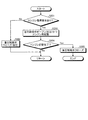
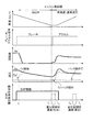
図1〜6を参照して、本発明の第1実施形態について説明する。図1は、本発明の第1実施形態に係る車両制御装置を搭載する車両2の構成を示す概略図であり、図2は、図1中の油圧制御装置1の概略構成を示す図であり、図3は、車速に応じた必要ベルト挟圧(セカンダリ圧)Pdの一例を示す図であり、図4は、本実施形態の車両制御装置により実施されるアキュムレータ44の蓄圧処理を示すフローチャートであり、図5は、本実施形態の車両制御装置により実施されるアキュムレータ44の吐出処理を示すフローチャートであり、図6は、アイドリングストップ走行中及びアイドリングストップ走行からの復帰時の本実施形態の車両制御装置によるセカンダリ圧Pd及びクラッチ圧Pc1の制御の一例を示すタイミングチャートである。[First Embodiment]
A first embodiment of the present invention will be described with reference to FIGS. FIG. 1 is a schematic diagram showing a configuration of a vehicle 2 equipped with a vehicle control device according to a first embodiment of the present invention, and FIG. 2 is a diagram showing a schematic configuration of a
まず、図1を参照して、本実施形態に係る車両制御装置を搭載する車両2の構成について説明する。図1に示すように、この車両2は、走行時における動力源としてのエンジン3と、駆動輪4と、動力伝達装置5と、油圧制御装置1と、ECU(Electronic Control Unit:電子制御ユニット)7とを備える。
First, with reference to FIG. 1, the structure of the vehicle 2 carrying the vehicle control apparatus which concerns on this embodiment is demonstrated. As shown in FIG. 1, the vehicle 2 includes an engine 3 as a power source during driving, a drive wheel 4, a power transmission device 5, a
エンジン3は、車両2を走行させる走行用駆動源(原動機)であり、燃料を消費して車両2の駆動輪4に作用させる動力を発生させる。エンジン3は、燃料の燃焼に伴って機関出力軸であるクランクシャフト8に機械的な動力(エンジントルク)を発生させ、この機械的動力をクランクシャフト8から駆動輪4に向けて出力可能である。 The engine 3 is a driving source (prime mover) that drives the vehicle 2, and generates power that consumes fuel and acts on the driving wheels 4 of the vehicle 2. The engine 3 can generate mechanical power (engine torque) on the crankshaft 8 that is an engine output shaft as the fuel burns, and can output this mechanical power from the crankshaft 8 toward the drive wheels 4. .
動力伝達装置5は、エンジン3から駆動輪4へ動力を伝達するものである。動力伝達装置5は、エンジン3から駆動輪4への動力の伝達経路中に設けられ、液状媒体としてのオイルの圧力(油圧)によって作動する。 The power transmission device 5 transmits power from the engine 3 to the drive wheels 4. The power transmission device 5 is provided in a power transmission path from the engine 3 to the drive wheel 4 and is operated by the pressure (hydraulic pressure) of oil as a liquid medium.
より詳細には、動力伝達装置5は、トルクコンバータ9、前後進切替機構10、無段変速機構11、減速機構12、デファレンシャルギヤ13等を含んで構成される。動力伝達装置5は、エンジン3のクランクシャフト8と無段変速機構11のインプットシャフト14とがトルクコンバータ9、前後進切替機構10等を介して接続され、無段変速機構11のアウトプットシャフト15が減速機構12、デファレンシャルギヤ13、駆動軸16等を介して駆動輪4に接続される。
More specifically, the power transmission device 5 includes a torque converter 9, a forward /
トルクコンバータ9は、エンジン3と前後進切替機構10との間に配置され、エンジン3から伝達された動力のトルクを増幅させて(又は維持して)、前後進切替機構10に伝達することができる。トルクコンバータ9は、回転自在に対向配置されたポンプインペラ9a及びタービンランナ9bを備え、フロントカバー9cを介してポンプインペラ9aをクランクシャフト8と一体回転可能に結合し、タービンランナ9bを前後進切替機構10に連結して構成されている。そして、これらポンプインペラ9a及びタービンランナ9bの回転に伴って、ポンプインペラ9aとタービンランナ9bとの間に介在された作動油などの粘性流体が循環流動することにより、その入出力間の差動を許容しつつトルクを増幅して伝達することが可能である。
The torque converter 9 is disposed between the engine 3 and the forward /
また、トルクコンバータ9は、タービンランナ9bとフロントカバー9cとの間に設けられ、タービンランナ9bと一体回転可能に連結されたロックアップクラッチ9dをさらに備える。このロックアップクラッチ9dは、後述の油圧制御装置1から供給されるオイルの圧力によって作動し、フロントカバー9cとの係合状態(ロックアップON)と解放状態(ロックアップOFF)とに切り替えられる。ロックアップクラッチ9dがフロントカバー9cと係合している状態では、フロントカバー9c(すなわちポンプインペラ9a)とタービンランナ9bが係合され、ポンプインペラ9aとタービンランナ9bとの相対回転が規制され、入出力間の差動が禁止されるので、トルクコンバータ9は、エンジン3から伝達されたトルクをそのまま前後進切替機構10に伝達する。
The torque converter 9 further includes a lock-up clutch 9d that is provided between the
前後進切替機構10は、エンジン3からの動力(回転出力)を変速可能であると共に、その回転方向を切替可能である。前後進切替機構10は、遊星歯車機構17、摩擦係合要素としての前後進切替クラッチ(フォワードクラッチ)C1及び前後進切替ブレーキ(リバースブレーキ)B1等を含んで構成される。遊星歯車機構17は、相互に差動回転可能な複数の回転要素としてサンギヤ、リングギヤ、キャリア等を含んで構成される差動機構であり、前後進切替クラッチC1及び前後進切替ブレーキB1は、遊星歯車機構17の作動状態を切り替えるための係合要素であり、例えば多板クラッチなどの摩擦式の係合機構等によって構成することができ、ここでは油圧式の湿式多板クラッチを用いる。
The forward /
前後進切替機構10は、後述の油圧制御装置1から供給されるオイルの圧力によって前後進切替クラッチC1、前後進切替ブレーキB1が作動し作動状態が切り替えられる。前後進切替機構10は、前後進切替クラッチC1が係合状態(ON状態)、前後進切替ブレーキB1が解放状態(OFF状態)である場合に、エンジン3からの動力を正転回転(車両2が前進する際にインプットシャフト14が回転する方向)でインプットシャフト14に伝達する。前後進切替機構10は、前後進切替クラッチC1が解放状態、前後進切替ブレーキB1が係合状態である場合に、エンジン3からの動力を逆転回転(車両2が後進する際にインプットシャフト14が回転する方向)でインプットシャフト14に伝達する。前後進切替機構10は、ニュートラル時には、前後進切替クラッチC1、前後進切替ブレーキB1共に解放状態とされる。本実施形態では、このような前後進切替クラッチC1及び前後進切替ブレーキB1の係合/解除の制御を行う制御系をまとめて「C1制御系」18と呼ぶ。
In the forward /
無段変速機構11は、エンジン3から駆動輪4への動力の伝達経路における前後進切替機構10と駆動輪4との間に設けられ、エンジン3の動力を変速して出力可能な変速装置である。無段変速機構11は、後述の油圧制御装置1から供給されるオイルの圧力によって作動する。
The continuously
無段変速機構11は、インプットシャフト14に伝達(入力)されるエンジン3からの回転動力(回転出力)を所定の変速比で変速して変速機出力軸であるアウトプットシャフト15に伝達し、このアウトプットシャフト15から駆動輪4に向けて変速された動力を出力する。無段変速機構11は、より詳細には、インプットシャフト(プライマリシャフト)14に連結されたプライマリプーリ20、アウトプットシャフト(セカンダリシャフト)15に連結されたセカンダリプーリ21、プライマリプーリ20とセカンダリプーリ21との間に掛け渡されたベルト22などを含んで構成されるベルト式の無段自動変速機(Continuously Variable Transmission:CVT)である。
The continuously
プライマリプーリ20は、プライマリシャフト14の軸方向に移動可能な可動シーブ20a(プライマリシーブ)と、固定シーブ20bとを同軸に対向配置することにより形成され、同様に、セカンダリプーリ21は、セカンダリシャフト15の軸方向に移動可能な可動シーブ21a(セカンダリシーブ)と、固定シーブ21bとを同軸に対向配置することにより形成される。ベルト22は、これら可動シーブ20a,21aと固定シーブ20b,21bとの間に形成されたV字溝に掛け渡されている。
The
そして、無段変速機構11では、後述の油圧制御装置1からプライマリプーリ20のプライマリシーブ油圧室23、セカンダリプーリ21のセカンダリシーブ油圧室24に供給されるオイルの圧力(プライマリ圧、セカンダリ圧)に応じて、可動シーブ20a,21aが固定シーブ20b,21bとの間にベルト22を挟み込む力(ベルト挟圧力)を、プライマリプーリ20及びセカンダリプーリ21の個々で制御することができる。これにより、プライマリプーリ20及びセカンダリプーリ21のそれぞれにおいて、V字幅を変更してベルト22の回転半径を調節することができ、プライマリプーリ20の入力回転速度に相当する入力回転数(プライマリ回転数)とセカンダリプーリ21の出力回転速度に相当する出力回転数(セカンダリ回転数)との比である変速比を無段階に変更することが可能となっている。また、プライマリプーリ20及びセカンダリプーリ21のベルト挟圧力が調整されることで、これに応じたトルク容量で動力を伝達することが可能となっている。
In the continuously
減速機構12は、無段変速機構11からの動力の回転速度を減速してデファレンシャルギヤ13に伝達する。デファレンシャルギヤ13は、減速機構12からの動力を、各駆動軸16を介して各駆動輪4に伝達する。デファレンシャルギヤ13は、車両2が旋回する際に生じる旋回の中心側、つまり内側の駆動輪4と、外側の駆動輪4との回転速度の差を吸収する。
The
上記のように構成される動力伝達装置5は、エンジン3が発生させた動力をトルクコンバータ9、前後進切替機構10、無段変速機構11、減速機構12、デファレンシャルギヤ13等を介して駆動輪4に伝達することができる。この結果、車両2は、駆動輪4の路面との接地面に駆動力[N]が生じ、これにより走行することができる。
The power transmission device 5 configured as described above drives the power generated by the engine 3 via a torque converter 9, a forward /
油圧制御装置1は、流体としてのオイルの油圧によってトルクコンバータ9のロックアップクラッチ9d、前後進切替機構10の前後進切替クラッチC1及び前後進切替ブレーキB1、無段変速機構11のプライマリシーブ20a及びセカンダリシーブ21a等を含む動力伝達装置5を作動させるものである。油圧制御装置1は、例えば、ECU7により制御される種々の油圧制御回路を含んで構成される。油圧制御装置1は、複数の油路、オイルリザーバ、オイルポンプ、複数の電磁弁などを含んで構成され、後述するECU7からの信号に応じて、動力伝達装置5の各部に供給されるオイルの流量あるいは油圧を制御する。また、この油圧制御装置1は、動力伝達装置5の所定の箇所の潤滑を行う潤滑油供給装置としても機能する。
The
ECU7は、車両2の各部の駆動を制御するものである。ECU7は、物理的には、CPU(Central Processing Unit)、RAM(Random Access Memory)、ROM(Read Only Memory)及びインターフェースを含む周知のマイクロコンピュータを主体とする電子回路である。ECU7の機能は、ROMに保持されるアプリケーションプログラムをRAMにロードしてCPUで実行することによって、CPUの制御のもとで車両2内の各種装置を動作させるとともに、RAMやROMにおけるデータの読み出し及び書き込みを行うことで実現される。本実施形態では、ECU7は、上述の油圧制御装置1を制御することによって、トルクコンバータ9、前後進切替機構10、無段変速機構11など動力伝達装置5の各部の制御を行う。なお、ECU7は、上記の機能に限定されず、車両2の各種制御に用いるその他の各種機能も備えている。
The
また、上記のECU7とは、エンジン3を制御するエンジンECU、動力伝達装置5(油圧制御装置1)を制御するT/M ECU、アイドリングストップ(S&S(スタート&ストップ))制御を実行するためのS&S ECUなどの複数のECUを備える構成であってもよい。
The
次に、図2を参照して本実施形態に係る油圧制御装置1の構成について説明する。
Next, the configuration of the
図2に示すように、油圧制御装置1は、動力伝達装置5の各部にオイルを供給するオイル供給源として、エンジン3(以下「Eng.」とも表記する)の駆動により駆動される機械式のメカポンプ(機械ポンプ)31を備えている。メカポンプ31は、油圧制御装置1内のドレン34に貯留されたオイルをストレーナ35で濾過した後に吸入圧縮して吐出する。メカポンプ31は、吐出したオイルを、油圧経路36を介して動力伝達装置5に供給することができる。
As shown in FIG. 2, the
油圧経路36には、プライマリレギュレータバルブ39が設けられている。プライマリレギュレータバルブ39は、メカポンプ31で発生された油圧を調圧するものである。プライマリレギュレータバルブ39には、SLSリニアソレノイド40により制御圧Pslsが供給され、プライマリレギュレータバルブ39は、この制御圧Pslsに応じて、油圧経路36内の油圧を調整する。そして、プライマリレギュレータバルブ39によって調圧された油圧経路36内の油圧がライン圧PLとして用いられる。
A
プライマリレギュレータバルブ39は、例えば、弁本体内で弁体(スプール)がその軸方向に摺動して流路の開閉もしくは切替を行うスプール弁を適用することができ、入力ポートに油圧経路36が接続され、パイロット圧を入力するパイロットポートにSLSリニアソレノイド40が接続され制御圧Pslsが入力され、出力ポートからライン圧PLの調圧により発生する余剰流を排出するよう構成することができる。
As the
メカポンプ31は、油圧経路36を介して、前後進切替機構10のC1制御系18(前後進切替クラッチC1及び前後進切替ブレーキB1)と、無段変速機構11(プライマリシーブ20aのプライマリシーブ油圧室23及びセカンダリシーブ21aのセカンダリシーブ油圧室24)に対して、プライマリレギュレータバルブ39によってライン圧PLに調圧された油圧を供給可能に接続されている。
The
無段変速機構11(プライマリシーブ20a及びセカンダリシーブ21a)へ接続される油圧経路36は、プライマリシーブ20aのプライマリシーブ油圧室23へ油圧を供給する第1油路36aと、セカンダリシーブ21aのセカンダリシーブ油圧室24へ油圧を供給する第2油路36bとに分岐される。
The
このうち第2油路36b上には、LPM(Line Pressure Modulator)No.1バルブ(ベルト挟圧制御弁)41が設けられている。LPM No.1バルブ41は、ライン圧PLを元圧として調圧された油圧を出力する。LPM No.1バルブ41には、SLSリニアソレノイド40により制御圧Pslsが供給される。
Of these, on the
LPM No.1バルブ41は、例えばスプール弁であり、ECU7によりデューティ制御されるSLSリニアソレノイド40の出力油圧Pslsをパイロット圧として、バルブ内に導入されるライン圧PLを元圧として調圧(減圧)された油圧を出力する。LPM No.1バルブ41から調圧して出力された油圧は、セカンダリ圧Pd(ベルト挟圧)として用いられ、セカンダリシーブ油圧室24に供給される。つまり、LPM No.1バルブ41は、制御圧Pslsに応じてセカンダリ圧Pdを制御する。セカンダリシーブ油圧室24に供給されたセカンダリ圧Pdに応じてセカンダリシーブ21aの推力が変化し、無段変速機構11のベルト挟圧力が増減させられる。
LPM No. The 1
なお、第2油路36b上のLPM No.1バルブ41とセカンダリシーブ油圧室24との間には、セカンダリ圧Pdを検出する圧力センサ43が設けられており、検出したセカンダリ圧Pdの情報をECU7に送信するよう構成されている。
Note that the LPM No. on the
第1油路36a上には、第1変速制御弁47及び第2変速制御弁48が設けられている。第1変速制御弁47は、ECU7によりデューティ制御される第1デューティソレノイド(DS1)49から供給される制御圧Pds1に応じて、プライマリシーブ油圧室23へのオイル供給を調整する。また、第2変速制御弁48は、ECU7によりデューティ制御される第2デューティソレノイド(DS2)50から供給される制御圧Pds2に応じて、プライマリシーブ油圧室23からのオイル排出を調整する。
A first
つまり、第1デューティソレノイド49が作動すると、第1変速制御弁47からオイルがプライマリシーブ油圧室23に導入され、プライマリシーブ20aがプライマリプーリ20の溝幅を狭める方向に移動して、この結果、ベルト22の掛径が増加してアップシフトする。第2デューティソレノイド50が作動すると、第2変速制御弁48によりプライマリシーブ油圧室23からオイルが排出され、プライマリシーブ20aがプライマリプーリ20の溝幅を広げる方向に移動して、この結果ベルト22の掛径が減少してダウンシフトする。このように、第1デューティソレノイド49及び第2デューティソレノイド50を作動させて制御圧Pds1,Pds2を調整することで、プライマリシーブ油圧室23内のオイル量を変化させ、無段変速機構11の変速比を制御することができる。
That is, when the
C1制御系18へ接続される油圧経路36上には、LPM No.2バルブ(調圧弁)54が設けられている。LPM No.2バルブ54は、LPM No.1バルブ41と同様に例えばスプール弁であり、バルブ内に導入されるライン圧PLを元圧として調圧(減圧)された所定の油圧Plpm2を出力する。
On the
油圧経路36は、LPM No.2バルブ54の下流側で第3油路36c、第4油路36d、第5油路36eに分岐されている。第3油路36cは、上述のSLSリニアソレノイド40に接続されている。SLSリニアソレノイド40は、ECU7から送信されたデューティ信号(デューティ値)によって決まる電流値に応じて、制御圧を発生させる電磁バルブであり、本実施形態では、入力された油圧Plpm2から制御圧Pslsを出力し、LPM No.1バルブ41、プライマリレギュレータバルブ39及びセカンダリレギュレータバルブ51へ制御圧Pslsを供給している。
The
第4油路36dは、ソレノイド調整バルブ55に接続されている。ソレノイド調整バルブ55は、LPM No.2バルブ54と同様に例えばスプール弁であり、入力される油圧Plpm2を元圧として調圧された所定の油圧Psmを出力する。
The
第4油路36dのソレノイド調整バルブ55より下流には、さらに第1デューティソレノイド(DS1)49、第2デューティソレノイド(DS2)50、SLリニアソレノイド56、及びDSUリニアソレノイド57に並列接続されている。第1デューティソレノイド(DS1)49、第2デューティソレノイド(DS2)50、SLリニアソレノイド56、及びDSUリニアソレノイド57は、SLSリニアソレノイド40と同様に、ECU7から送信されたデューティ信号(デューティ値)によって決まる電流値に応じて、制御圧を発生させる電磁バルブであり、本実施形態では、ソレノイド調整バルブ55により調圧された油圧Psmから、それぞれ制御圧Pds1,Pds2,Psl,Pdsuを出力する。第1デューティソレノイド49及び第2デューティソレノイド50により生成される制御圧Pds1,Pds2は、無段変速機構11のプライマリシーブ油圧室23のオイル量を制御する第1変速制御弁47及び第2変速制御弁48へ供給される。SLリニアソレノイド56及びDSUリニアソレノイド57により生成される制御圧Psl,Pdsuは、後述する第5油路36e上のシフトバルブ61や、L/U制御系53(トルクコンバータ9のロックアップクラッチ9dの係合/解放を制御する制御系)に供給される。
Further downstream of the
第5油路36eからは、さらに第6油路36fが分岐されており、この第6油路36fは、油圧Plpm2のオイルをオリフィス58を経由して動力伝達装置5内の所定の箇所の各部潤滑などに供給できるよう構成されている。なお、図2には図示しないが各部潤滑に供給されたオイルは、最終的にドレン34に戻されるよう油路が形成されている。
A
第6油路36fより下流側の第5油路36e上には、SLCリニアソレノイド60(クラッチ圧制御弁)が設けられている。SLCリニアソレノイド60は、SLSリニアソレノイド40などと同様に、ECU7から送信されたデューティ信号(デューティ値)によって決まる電流値に応じて、制御圧を発生させる電磁バルブである。本実施形態では、SLCリニアソレノイド60は、油圧Plpm2を元圧として、C1制御系18へ供給する制御圧(クラッチ圧)Pc1を制御する。
An SLC linear solenoid 60 (clutch pressure control valve) is provided on the
また、第5油路36eには、このSLCリニアソレノイド60を迂回する迂回経路36gが形成されており、SLCリニアソレノイド60の下流側にて、第5油路36eと共にシフトバルブ61(切替弁)に接続されている。
Further, a
シフトバルブ61は、C1制御系18に供給する油圧を、SLCリニアソレノイド60により調整されたクラッチ圧Pc1、または、迂回経路36gから入力されるLPM No.2バルブ54により調圧された油圧Plpm2から選択するものである。シフトバルブ61は、SLリニアソレノイド56及びDSUリニアソレノイド57により生成される制御圧Psl,Pdsuに応じて切り替えられる。本実施形態では、シフトバルブ61は、SLリニアソレノイド56から制御圧Pslが入力される場合には、SLCリニアソレノイド60により調整されたクラッチ圧Pc1をC1制御系18に供給するよう切り替わり、一方、DSUリニアソレノイド57から制御圧Pdsuが入力される場合には、迂回経路36gからの油圧Plpm2をC1制御系18に供給するよう切り替わる。
The
第5油路36eのシフトバルブ61の下流側には、さらにマニュアルバルブ62が設けられている。マニュアルバルブ62は、車両2の運転者のシフト操作に連動して油路を切り替えるものである。例えば、シフトポジションが「D(前進)」の場合には、マニュアルバルブ62は、C1制御系18のうち前後進切替クラッチC1へ油路を接続し、前後進切替クラッチC1を制御可能とする。「R(後進)」の場合には、マニュアルバルブ62は、C1制御系18のうち前後進切替ブレーキB1へ油路を接続し、前後進切替ブレーキB1を制御可能とする。シフトポジションが「N(ニュートラル)」の場合には、マニュアルバルブ62は油路を前後進切替クラッチC1及び前後進切替ブレーキB1のどちらへも接続しない。
A
プライマリレギュレータバルブ39の出力ポートには、セカンダリレギュレータバルブ51が接続されている。このセカンダリレギュレータバルブ51も、プライマリレギュレータバルブ39と同様にスプール弁であり、ECU7によりデューティ制御されるSLSリニアソレノイド40の制御圧Pslsに応じて、プライマリレギュレータバルブ39から排出される余剰流の油圧を調圧するものである。
A
プライマリレギュレータバルブ39の出力ポートには、さらにトルクコンバータ9のロックアップクラッチ9dの係合/解放を制御するL/U制御系53が接続されており、プライマリレギュレータバルブ39から余剰流が発生したときには、セカンダリレギュレータバルブ51によって余剰流が調圧され、この調圧された余剰流がL/U制御系53(または無段変速機構11より低圧で制御可能な低圧制御系)に供給されるよう構成されている。
An L /
また、セカンダリレギュレータバルブ51は、出力ポートから余剰流の調圧により発生するさらなる余剰流を、動力伝達装置5内の所定の箇所の各部潤滑などに供給できるよう構成されている。図2には図示しないが、L/U制御系53や各部潤滑などに供給された余剰流は、最終的にドレン34に戻されるよう油路が形成されている。
Further, the
なお、図2に示す例では、単一のSLSリニアソレノイド40が、プライマリレギュレータバルブ39、セカンダリレギュレータバルブ51、LPM No.1バルブ41の制御圧Pslsを生成する構成としたが、各バルブごとにそれぞれ個別のリニアソレノイドを設けて、ECU7により制御圧を個別に制御可能とする構成であってもよい。
In the example shown in FIG. 2, a single SLS
ここで、特に本実施形態の車両2には、燃費向上などのため、車両2の停車中または走行中にエンジン3を停止させる機能、所謂アイドリングストップ機能が備えられおり、特に減速走行時など、車両2の走行中に所定の条件を満たす場合に、エンジン3の停止とクラッチの解除とを併せて行った状態で走行するアイドリングストップ走行を実施可能に構成されている。アイドリングストップ走行中にはエンジン3が停止するため、エンジン駆動により作動するメカポンプ31も停止する。そこで、本実施形態の油圧制御装置1は、このようなアイドリングストップ機能の実行時、すなわちエンジン3の停止時におけるメカポンプ31の代替として、電気で作動するモータ32の駆動により作動する電動ポンプ33を備えている。
Here, in particular, the vehicle 2 of the present embodiment is provided with a function of stopping the engine 3 while the vehicle 2 is stopped or traveling, in order to improve fuel consumption, so-called idling stop function, When predetermined conditions are satisfied while the vehicle 2 is traveling, it is configured to be able to perform idling stop traveling that travels in a state in which the engine 3 is stopped and the clutch is released. Since the engine 3 stops during idling stop travel, the
電動ポンプ33は、メカポンプ31と同様に油圧制御装置1内のドレン34に貯留されたオイルをストレーナ35で濾過した後に吸入圧縮して吐出するオイルポンプである。電動ポンプ33は、図2に示すように、その吐出口に接続される出口流路37を介して、油圧経路36の第2油路36bに連通されている。この出口流路37上には、油圧経路36の第2油路36bから電動ポンプ33へのオイルの逆流を防止するチェック弁38が設けられている。このように、電動ポンプ33は、アイドリングストップ機能の実行中のエンジン3が停止してメカポンプ31が停止されたときに、モータ32駆動により油圧経路36の第2油路36bに油圧Peop1のオイルを供給し、無段変速機構11のベルト滑りを抑制するのに充分なセカンダリ圧(ベルト挟圧)を確保できるよう構成されている。
The
第2油路36b上には、LPM No.1バルブ41より上流側に、チェック弁(昇圧用チェック弁)52が設けられ、電動ポンプ33から吐出されたオイルが上流側(メカポンプ31、C1制御系18の側)へ逆流したり、プライマリシーブ20aへ接続する第1油路36aへ流入するのを防止して、電動ポンプ33によるセカンダリ圧Pdの昇圧を効率よく行うことができるよう構成されている。そして、電動ポンプ33からの出口流路37は、このチェック弁52とセカンダリシーブ油圧室24との間、より好適には、チェック弁52とLPM No.1バルブ41との間にて油圧経路36に接続されている。
On the
なお、電動ポンプ33が吐出可能なオイルの油圧Peop1は、アイドリングストップ走行中のセカンダリ圧Pdが、無段変速機構11のベルト22の滑り発生が回避できる最低限のベルト挟圧力を確保するために要求されるレベルを維持できる程度であればよい。このようなベルト挟圧力は、車両2がアイドリングストップ走行中に急制動、悪路走行、路面変化などの外乱が駆動輪4側から動力伝達装置5に入力され、大きなトルク変動が発生した場合でも、このトルク変動に耐えてベルト滑りを防止できるものである。本実施形態の油圧制御装置1では、消費電力10ワット程度の電動ポンプを用いれば、このようなベルト挟圧力を実現可能な油圧Peop1を出力することができる。
The oil pressure Peop1 that can be discharged by the
また、電動ポンプ33は、ECU7からの制御指令に基づきモータ32の駆動力を調整することにより、吐出量を制御可能に構成されている。例えば、車速に応じて吐出量を変更して油圧Peop1を制御することで、車速に応じた必要ベルト挟圧力を発生させるためのセカンダリ圧(ベルト挟圧)Pdを確保することができる。なお、車速と必要ベルト挟圧(セカンダリ圧Pd)との関係は、例えば図3に示すように、車速の超低速域では必要ベルト挟圧が一定であり、その後車速の増加に応じて必要ベルト挟圧も単調増加し、車速が所定値に到達すると必要ベルト挟圧が再び一定値となるよう設定することができる。
The
さらに、本実施形態では、C1制御系18へ接続される油圧経路36(好ましくは第5油路36e)上に、アキュムレータ44が接続されている。アキュムレータ44は、メカポンプ31の駆動時に、メカポンプ31から供給された油圧を内部に蓄えて保持(蓄圧)しておき、必要に応じてこの保持された油圧をC1制御系18に供給できるよう構成されている。
Furthermore, in this embodiment, the
アキュムレータ44は、既知の構成により実現できるが、例えばガス式のアキュムレータの場合には、内部にピストンが配置され、このピストンにより密閉された内部空間にガスが充填されている。蓄圧時には、ピストンが押し込まれてオイルが内部に蓄えられる。このとき、ガスは圧縮され、この圧縮されたガスの圧力と蓄えられたオイルの圧力とは釣り合っている。また、吐出時には、ガスの膨張力を利用してピストンを押し出すことで、蓄圧されたオイルを内部から吐出して、C1制御系18に供給する。
The
アキュムレータ44は、ピストンの摺動に応じて内部のガスの容積を最小値Va_minから最大値Va_maxの間で変化させることができ、ガス容積が最小値Va_minのとき、ガスの圧力は最大値Pa_maxとなり、ガス容積が最大値Va_maxのとき、ガスの圧力は最小値Pa_minとなるよう構成されている。ここで、ガス圧の最小値Pa_minは、パック詰め圧(前後進切替クラッチC1のクラッチプレートが摩擦材と当接する(詰まる)状態となるようクラッチパック(前後進切替クラッチC1の作動油室)に作動油を充填できる油圧)に相当する。また、ガス圧の最大値Pa_maxは、アキュムレータ44からの蓄圧の吐出時に、クラッチ圧Pc1を少なくともPa_min(パック詰め圧)に維持できるような圧力として予め設定されている。
The
アキュムレータ44の蓄圧及び吐出は、このアキュムレータ44と第5油路36eとの間に設けられる蓄圧制御弁45により制御される。蓄圧制御弁45が閉じることでアキュムレータ44の内部にオイルが蓄圧され、蓄圧制御弁45が開くことで蓄圧されていたオイルが吐出される。蓄圧制御弁45の開閉動作は、ECU7によって制御されている。蓄圧制御弁45は、例えば電磁ポペット弁であり、ECU7により供給電流を調整することで開閉を切り替えられる。なお、蓄圧制御弁45は、スプール弁など他の弁構造を用いてもよい。
Accumulation and discharge of the
アキュムレータ44と蓄圧制御弁45との間には、アキュムレータ44に蓄圧されるオイルの圧力(アキュムレータ圧)Paccを検出する圧力センサ46が設けられ、検出したアキュムレータ圧Paccの情報をECU7に送信するよう構成されている。
Between the
アキュムレータ44及び蓄圧制御弁45が油圧経路36と接続される位置は、SLCリニアソレノイド60より上流側であり、好ましくは、LPM No.2バルブ54より下流側であり、より好ましくは、油圧経路36の第5油路36eのうち第6油路36fとの分岐より下流側である。また、油圧経路36上のアキュムレータ44及び蓄圧制御弁45の接続位置より上流側(図2の例では、第6油路36fより下流の位置)には、チェック弁59が設けられ、アキュムレータ44から吐出されたオイルの上流側への逆流を防止して、アキュムレータ44による油圧Plpm2の昇圧を効率よく行うことができるよう構成されている。
The position where the
なお、本実施形態では、以上に述べた車両1の構成要素のうち、少なくともエンジン3、動力伝達装置5(特に無段変速機構11及びC1制御系18(前後進切替クラッチC1))、及び油圧制御装置1(特にメカポンプ31、電動ポンプ33、アキュムレータ44)が、本実施形態に係る車両制御装置として機能するものである。
In the present embodiment, among the components of the
次に、図4〜6を参照して、本実施形態に係る車両制御装置の動作について説明する。図4,5に示す各処理は、油圧制御装置1の蓄圧制御弁45や、車両2の各種センサ情報などを利用して、ECU7により実施される。
Next, with reference to FIGS. 4-6, operation | movement of the vehicle control apparatus which concerns on this embodiment is demonstrated. Each process shown in FIGS. 4 and 5 is performed by the
まず図4を参照して、本実施形態に係る車両制御装置の油圧制御装置1におけるアキュムレータ44の蓄圧処理について説明する。この処理は、アイドリングストップ機能の非実行時、言い換えると、車両2の通常走行中に実施される。通常走行中とは、エンジン3が駆動しメカポンプ31が作動している状態を意味する。また、この処理の初期状態では、蓄圧制御弁45は閉弁されている。
First, with reference to FIG. 4, the pressure accumulation process of the
まず、アキュムレータ44の蓄圧処理の禁止条件が満たされ、蓄圧禁止中とされているか否かが確認される(S101)。ここで、蓄圧処理の禁止条件とは、例えば、アイドリングストップ走行に移行する直前に、前後進切替クラッチC1を解放する制御が行われている状態や、アイドリングストップ走行から復帰し、前後進切替クラッチC1を係合する制御が行われている状態など、SLCリニアソレノイド60によりクラッチ圧Pc1が制御されており、C1制御系18の制御に即応性が必要な場合を含むことができる。また、エンジン回転数が低い状態、油圧制御装置1内の油温が高い状態、変速速度が大きい状態なども含むことができる。
First, it is confirmed whether or not the accumulation condition prohibition condition of the
ステップS101において、蓄圧禁止中である場合には、蓄圧制御弁45がクローズ(閉弁)されたまま(S102)、ステップS101にリターンされる。一方、ステップS101において蓄圧禁止中ではない場合には、蓄圧制御弁45がオープン(開弁)される(S103)。これによりアキュムレータ44内に第5油路36eからオイルが導入され、蓄圧が行われる。
In step S101, if pressure accumulation is prohibited, the pressure
次に図5を参照して、本実施形態に係る車両制御装置の油圧制御装置1におけるアキュムレータ44の吐出処理について説明する。この処理は、アイドリングストップ機能の実行時に実施される。また、図5の処理の前提として、図4に示した蓄圧処理が実行済みであり、アキュムレータ圧Paccが所定値以上で蓄圧制御弁45がクローズされているものとする。
Next, the discharge process of the
まず、エンジン復帰要求が有ったか否かが確認される(S201)。エンジン復帰要求とは、アイドリングストップ走行からエンジン走行に復帰させる指令であり、例えばブレーキがオフとなったり、ブレーキの負圧が低下したり、バッテリ電圧が低下するなどの状態をトリガとして検知される。 First, it is confirmed whether or not there is an engine return request (S201). The engine return request is a command for returning from idling stop running to engine running, and is detected using, for example, a state where the brake is turned off, the negative pressure of the brake is lowered, or the battery voltage is lowered as a trigger. .
ステップS201においてエンジン復帰要求が無かった場合には、蓄圧制御弁45をクローズしたまま(S202)、アキュムレータ44内のオイルを保圧して、ステップS201にリターンする。
If there is no engine return request in step S201, the pressure in the
一方、ステップS201においてエンジン復帰要求が有った場合には、エンジン3の再始動後に前後進切替クラッチC1の係合制御が実施されるまでに、クラッチ圧Pc1をパック詰め圧まで上げておく必要があるものとして、蓄圧制御弁45をオープンすると共に、スタータにエンジン起動要求を出してエンジン3の再起動制御を開始する(S203)。蓄圧制御弁45がオープンされることで、アキュムレータ44から蓄圧されたオイルが第5油路36eに吐出されて、クラッチ圧Pc1を増大し、パック詰め圧(概ね0.1MPa程度)を発生させることができる。
On the other hand, if there is an engine return request in step S201, it is necessary to increase the clutch pressure Pc1 to the pack packing pressure before the engagement control of the forward / reverse switching clutch C1 is performed after the engine 3 is restarted. As a result, the pressure
続いて、エンジン起動が完了したか否かが確認される(S204)。エンジン起動が完了していない場合には、ステップS201にリターンする。一方、エンジン起動が完了した場合には、SLCリニアソレノイド60によるクラッチ圧Pc1の制御応答性を向上させるべく、蓄圧制御弁45をクローズし(S205)、メカポンプ31から供給されるオイルが油圧経路36からアキュムレータ44に流入されるのを防止する。
Subsequently, it is confirmed whether or not the engine activation has been completed (S204). If the engine startup has not been completed, the process returns to step S201. On the other hand, when the engine start is completed, the pressure
ここで、本実施形態における、アイドリングストップ走行中及びアイドリングストップ走行からの復帰時のセカンダリ圧(ベルト挟圧)Pd及びクラッチ圧Pc1の推移について、図6のタイミングチャートを参照して説明する。図6のタイミングチャートには、車速、ブレーキ・アクセル信号、エンジン回転数Ne、油圧(セカンダリ圧Pd,クラッチ圧Pc1)、電動ポンプ33(EOP)及び蓄圧制御弁45の状態の時間遷移がそれぞれ表されている。
Here, transition of the secondary pressure (belt clamping pressure) Pd and the clutch pressure Pc1 during the idling stop traveling and at the return from the idling stop traveling in the present embodiment will be described with reference to the timing chart of FIG. The timing chart of FIG. 6 shows the time transition of the vehicle speed, brake / accelerator signal, engine speed Ne, oil pressure (secondary pressure Pd, clutch pressure Pc1), electric pump 33 (EOP), and pressure
まず時刻t1より前、すなわちアイドリングストップ走行(減速S&S)が開始される前において、アイドリングストップ走行へ移行する際エンジン3停止に伴うショックを防止するために、移行前に予め前後進切替クラッチC1が解放され(図中「C1解放」と示す)、これによりクラッチ圧Pc1も低減される。また、クラッチ解放とほぼ同時に電動ポンプ33(EOP)が始動する。なお、アイドリングストップ走行の実施判定は、例えばブレーキ信号を利用して行われる。 First, before the time t1, that is, before the idling stop traveling (deceleration S & S) is started, the forward / reverse switching clutch C1 is set in advance before the transition in order to prevent a shock caused by the stop of the engine 3 when transitioning to the idling stop traveling. The clutch pressure Pc1 is also reduced due to the release (indicated as “C1 release” in the figure). Further, the electric pump 33 (EOP) is started almost simultaneously with the release of the clutch. In addition, the execution determination of idling stop traveling is performed using, for example, a brake signal.
次に、時刻t1において、アイドリングストップ走行が開始されると、エンジン3が停止されてエンジン回転数Neが0に推移する。このとき、車両2の運転者によりブレーキ操作が継続して行われているため、車速は連続的に減速されている。電動ポンプ33は、この車速の変化に応じてモータ32により駆動されており、車速に応じた油圧Peop1を調整されたオイルを油圧経路36の第2油路36bに供給する。このため、無段変速機構11のセカンダリシーブ油圧室24に供給されるセカンダリ圧Pd(ベルト挟圧)も、車速の減速に応じて必要ベルト挟圧を確保しつつ連続的に減少されている。
Next, when idling stop traveling is started at time t1, the engine 3 is stopped and the engine speed Ne changes to zero. At this time, since the brake operation is continuously performed by the driver of the vehicle 2, the vehicle speed is continuously decelerated. The
次に、時刻t2において、アイドリングストップ走行が終了され、エンジン3の再起動制御が開始されると、蓄圧制御弁45が通電されて開弁され、アキュムレータ44に蓄圧されていたオイルが油圧経路36の第5油路36eに吐出される。これにより、第5油路36eの油圧Plpm2が増圧し、SLCリニアソレノイド60によってクラッチ圧Pc1をパック詰め圧まで増加させることができる。そして、再発進時に前後進切替クラッチC1を係合させる際の制御応答性を向上させるため、また、前後進切替クラッチC1の係合時のショック発生を防止するために、再発進が実施される時点(t3)までに、前後進切替クラッチC1のパック詰めを完了させておく(図中に「C1パック詰め」と示す)。なお、アイドリングストップ走行の終了判定(エンジン復帰要求)は、例えばブレーキ信号がオフに切り替わるのをトリガとして行われる。
Next, when the idling stop traveling is finished and the restart control of the engine 3 is started at time t2, the pressure
そして、時刻t3において、エンジン再始動制御が完了して再発進・通常走行に移行するときに、蓄圧制御弁45が閉弁される。また、電動ポンプ33も停止される。この後、エンジン3が駆動してメカポンプ31が作動し、セカンダリ圧Pd及びクラッチ圧Pc1がさらに増大される。
Then, at time t3, when the engine restart control is completed and the vehicle proceeds to re-start / normal travel, the pressure
また、通常走行中に、蓄圧処理の禁止条件から外れているとき(図6では時刻t4として示す)に、蓄圧制御弁45が通電されて開弁され、アキュムレータ44へオイルが蓄圧される。蓄圧制御弁45は、例えばアキュムレータ44に蓄圧されるオイルの圧力(アキュムレータ圧)Paccが所定値(例えばPa_max)に達したとき(図6では時刻t5として示す)に閉弁し、アキュムレータ44内のオイルを保圧する。
Further, during normal travel, when the pressure accumulation processing prohibition condition is deviated (shown as time t4 in FIG. 6), the pressure
次に、本実施形態に係る車両制御装置の効果について説明する。 Next, effects of the vehicle control device according to the present embodiment will be described.
本実施形態の車両制御装置は、エンジン3と、ベルト式無段変速機構11及びC1制御系18(前後進切替クラッチC1)を含む動力伝達装置5と、動力伝達装置5を作動させるために供給されるオイルの油圧を制御する油圧制御装置1と、を備えて車両2に搭載され、エンジン3の停止とC1制御系18(前後進切替クラッチC1)の解除とを行うアイドリングストップ機能を、車両停止時だけでなく、減速時などの車両走行中にも実行可能である。
The vehicle control device of the present embodiment is supplied to operate the engine 3, the power transmission device 5 including the belt type continuously
従来、アイドリングストップ機能を車両停止時に実行する場合には、動力伝達装置5のベルト式無段変速機構11が、エンジン再始動時のクランキングの影響を受けない程度のベルト挟圧力を確保できればよかった。具体的には、ベルト挟圧力を制御するセカンダリシーブ21aへ供給されるセカンダリ圧Pdとして0.3MPa程度の油圧が要求されていた。
Conventionally, when the idling stop function is executed when the vehicle is stopped, it is sufficient that the belt-type continuously
これに対し、本実施形態のように車両走行中にもアイドリングストップ機能を実行する場合には、より大きなベルト挟圧力が必要となる状況が考えられる。例えば、アイドリングストップ走行中に急制動、悪路走行、路面変化などの外乱による回転変動が駆動輪4側から動力伝達装置5に入力されると、この外乱入力によってトルク変動が発生し、ベルト式無段変速機構11においてベルト22の滑りが発生する虞があり、動力伝達に悪影響が出る場合がある。このような外乱入力の影響を受けないために確保すべきベルト挟圧力は、上記の車両停止時のものに比べて大きなものとなる。具体的には、セカンダリ圧Pdとして約1.5Mpa程度の油圧、約6(リットル/分)程度のオイル流量が要求され、また、数十ミリ秒での油圧応答性も求められる。
On the other hand, when the idling stop function is executed while the vehicle is running as in the present embodiment, a situation in which a larger belt clamping pressure is required can be considered. For example, when rotational fluctuations due to disturbances such as sudden braking, rough road running, and road surface changes are input to the power transmission device 5 from the driving wheel 4 during idling stop running, torque fluctuations are generated by the disturbance input, and the belt type There is a possibility that the
このようなベルト挟圧力を確保するために、メカポンプ31の代替として電動ポンプ33を利用した場合、すなわち、電動ポンプ33により油圧経路36へオイルを供給する構成とした場合、電動ポンプ33を非常に大きくする必要がある。例えば上記の例のように車両停止時に比べて5倍の油圧を発生させるには電動ポンプは約25倍の容積が必要であるし、車両停止時のアイドリングストップ機能のために消費電力が数十ワットクラスの電動ポンプで済んだのに対し、車両走行時のアイドリングストップ機能のためには消費電力がキロワットクラスの電動ポンプが必要となる。また、必要なベルト挟圧が大きくなると、電動ポンプ33からベルト式無段変速機構11までの油圧経路36内の漏れ流量も大きくなるため、漏れ流量の影響を考慮して電動ポンプをさらに大型化する必要がある。このような電動ポンプの大型化は、コスト増大や搭載性悪化などの問題が懸念される。
In order to secure such belt clamping pressure, when the
また、アイドリングストップ状態からの復帰時には、エンジン再起動の完了までにC1制御系18(前後進切替クラッチC1)を速やかに再始動可能な状態(作動可能な状態、クラッチパックを詰めた状態)にしておき、C1制御系18の制御応答性を確保しておくことが望ましい。
Further, when returning from the idling stop state, the C1 control system 18 (forward / reverse switching clutch C1) is brought into a state in which it can be restarted promptly (operational state, clutch pack packed state) until the engine restart is completed. It is desirable to ensure the control response of the
そこで、本実施形態の車両制御装置は、エンジン3の駆動により油圧制御装置1の油圧経路36を介して動力伝達装置5にオイルを供給するメカポンプ31と、アイドリングストップ機能の実行中のエンジン3が停止してメカポンプ31が停止されたときに、モータ32駆動によりベルト式無段変速機構11にオイルを供給する電動ポンプ33と、メカポンプ31により供給されるオイルを蓄圧し、アイドリングストップ機能からの復帰時に、蓄圧されたオイルをC1制御系18(前後進切替クラッチC1)に供給するアキュムレータ44と、を備えて構成される。
Therefore, the vehicle control device of the present embodiment includes a
上記の構成により、アイドリングストップ機能の実行中には、電動ポンプ33によりベルト式無段変速機構11にオイルが供給されるので、ベルト22の滑り発生を防止可能なベルト挟圧力を確保できるようセカンダリ圧Pdを昇圧して無段変速機構11に供給することができる。
With the above configuration, since the oil is supplied to the belt-type continuously
また、電動ポンプ33は、ベルト式無段変速機構11に直接的にオイルを供給するため、電動ポンプ33からベルト式無段変速機構11までの漏れ流量を低減させることが可能となり、電動ポンプ33の小型化が可能となる。
Further, since the
一方、アイドリングストップ機能から復帰してエンジン3が再始動する際には、アキュムレータ44により蓄圧されたオイルがC1制御系18に供給されるため、アイドリングストップ状態からの復帰時には、エンジン再起動の完了までにC1制御系18(前後進切替クラッチC1)を速やかに再始動可能な状態(作動可能な状態、クラッチパックを詰めた状態)にしておき、C1制御系18の制御応答性を確保することができる。
On the other hand, when the engine 3 is restarted after returning from the idling stop function, the oil accumulated by the
また、アキュムレータ44からのオイル供給の時期を、アイドリングストップ走行終了時からエンジン再起動までの短時間に限定できるため、また、アキュムレータ44の蓄圧はベルト挟圧力より要求油圧の低いC1制御系18の制御に利用されるため、アキュムレータ44の小型化が可能である。
In addition, since the timing of oil supply from the
このように、本実施形態の車両制御装置によれば、アイドリングストップ機能の実行時に油圧制御に用いる電動ポンプ33やアキュムレータ44の大型化を抑制できる。
Thus, according to the vehicle control device of the present embodiment, it is possible to suppress the increase in size of the
また、本実施形態に係る車両制御装置の油圧制御装置1は、油圧経路36のうちベルト式無段変速機構11のセカンダリシーブ21aに接続される第2油路36b上に、上流側へのオイルの逆流を防止するチェック弁52を備え、電動ポンプ33は、チェック弁52とセカンダリシーブ21aとの間にて油圧経路36(第2油路36b)に接続される。
In addition, the
この構成により、電動ポンプ33からオイルを吐出する際には、チェック弁52により油圧経路36の上流側へオイルが逆流するのが防止されるので、ベルト式無段変速機構11のセカンダリシーブ21aに接続される第2油路36b内のみで油圧を増加させることができる。これにより、セカンダリシーブ21aに供給されるセカンダリ圧Pdを効率よく昇圧させ、ベルト挟圧力を増加させることができるので、電動ポンプ33をより一層小型化することが可能となる。
With this configuration, when the oil is discharged from the
また、本実施形態に係る車両制御装置の油圧制御装置1は、チェック弁52の下流側にセカンダリシーブ21aへ供給する油圧であるベルト挟圧(セカンダリ圧Pd)を制御するLPM No.1バルブ41を備え、電動ポンプ33は、チェック弁52とLPM No.1バルブ41との間にて油圧経路36(第2油路36b)に接続される。
In addition, the
この構成により、電動ポンプ33から吐出されたオイルが第2油路36bに供給された後に、LPM No.1バルブ41にてセカンダリ圧Pdに調圧されるので、セカンダリ圧Pdを適宜制御することが可能となる。
With this configuration, after the oil discharged from the
また、本実施形態に係る車両制御装置の油圧制御装置1は、油圧経路36のうちC1制御系18に接続される第5油路36e上にC1制御系18へ供給する油圧であるクラッチ圧Pc1を制御するSLCリニアソレノイド60を備え、アキュムレータ44は、SLCリニアソレノイド60の上流側にて油圧経路36に接続される。
Further, the
この構成により、アキュムレータ44の吐出時には、アキュムレータ44から蓄圧されたオイルが第5油路36eに供給された後にSLCリニアソレノイド60にてクラッチ圧Pc1に調圧されるので、クラッチ圧Pc1を適宜制御可能である。これにより、エンジン再起動時にはクラッチ圧Pc1をパック詰め圧に精度良く制御することが可能となり、C1制御系18(前後進切替クラッチC1)の制御応答性を向上でき、また、エンジン起動時のクラッチ係合によるショックを低減できる。
With this configuration, when the
また、本実施形態に係る車両制御装置の油圧制御装置1は、油圧経路36のうちC1制御系18に接続される第5油路36e上のSLCリニアソレノイド60より上流側に、メカポンプ31から吐出されたオイルの油圧を調圧するLPM No.2バルブ54を備え、アキュムレータ44は、LPM No.2バルブ54とSLCリニアソレノイド60との間にて油圧経路36(第5油路36e)に接続される。
Further, the
この構成により、アキュムレータ44から吐出されるオイルが供給される範囲が第5油路36eの一部分に限定されるので、効率良く増圧を実施することが可能となり、アキュムレータ44をより一層小型化することが可能となる。
With this configuration, the range in which the oil discharged from the
また、本実施形態に係る車両制御装置の油圧制御装置1では、アキュムレータ44は、C1制御系18(前後進切替クラッチC1)の係合または解放動作中にはオイルの蓄圧を中止するよう構成される。この構成により、C1制御系18(前後進切替クラッチC1)の係合または解放動作中という、C1制御系18に高い制御応答性が求められるタイミングでは、アキュムレータ44の蓄圧処理を中止して、アキュムレータ44へ第5油路36e内のオイルが流入するのを防止でき、第5油路36eの油圧が変動するのを防止できる。これによりSLCリニアソレノイド60によるクラッチ圧Pc1の供給を安定させることができ、C1制御系18(前後進切替クラッチC1)の制御応答性を向上できる。
Further, in the
[第2実施形態]
次に、図7を参照して、本発明の第2実施形態について説明する。図7は、本発明の第2実施形態に係る車両制御装置の油圧制御装置1aの概略構成を示す図である。[Second Embodiment]
Next, a second embodiment of the present invention will be described with reference to FIG. FIG. 7 is a diagram showing a schematic configuration of the hydraulic control device 1a of the vehicle control device according to the second embodiment of the present invention.
図7に示すように、本実施形態に係る車両制御装置の油圧制御装置1aは、電動ポンプ33から吐出されたオイルの一部を、油圧経路36のうちC1制御系18に接続される第5油路36eに供給するように、電動ポンプ33の出口流路37と第5油路36eとを連通する第2出口流路63が設けられる点で、第1実施形態の油圧制御装置1と異なるものである。
As shown in FIG. 7, the hydraulic control device 1 a of the vehicle control device according to the present embodiment is configured to connect a part of the oil discharged from the
第2出口流路63は、チェック弁38より上流側で電動ポンプ33の出口流路37から分岐され、オリフィス64を介して第5油路36eに接続されている。第2出口流路63が第5油路36eと接続される位置は、SLCリニアソレノイド60より上流であり、好ましくはLPM No.2バルブ54より下流側、より好ましくは第6油路36fより下流側である。
The
また、本実施形態では、チェック弁59は、第6油路36fとの分岐より上流側かつ第3,4油路36c,36dより下流側の第5油路36e上に配置されている。本実施形態の油圧制御装置1aでは、このチェック弁59の配置によって、電動ポンプ33から供給されるオイルが、第5油路36eのうちチェック弁59とSLCリニアソレノイド60との間の領域と、各部潤滑へ通じる第6油路36fとを増圧する構成となっている。
In the present embodiment, the
C1制御系18は一般的に油圧制御装置1aの油面より高い位置に配置されているためアイドリングストップ走行(減速S&S)中に油圧供給が止まると、C1制御系18内の作動油が重力により落ちてゆき、エア(空気)が流入する状況(オイル落ち)となる場合がある。アイドリングストップ状態からの再発進時に、このオイル落ちによるエアの影響で油圧がすぐに立ち上がらなくなり、C1制御系18の応答性が悪化する虞がある。
Since the
そこで、本実施形態の油圧制御装置1aでは、電動ポンプ33から吐出されたオイルの一部を油圧経路36のうちC1制御系18に接続される第5油路36eに供給する構成をとることにより、アイドリングストップ走行中のオイル落ちを防止することが可能となる。また、電動ポンプ33から吐出されるオイルが第6油路36fを介して各部潤滑に利用できるので、アイドリングストップ走行中のオイル流量が少ない状況でも潤滑確保が可能となる。
Therefore, in the hydraulic control device 1a of the present embodiment, a part of the oil discharged from the
なお、電動ポンプ33からC1制御系18への油圧供給は、オイル落ち防止を目的とした低圧(数十kPaレベル)でよいため、消費流量増加が抑えられ、電動ポンプ33の大型化を抑制できる。
In addition, since the hydraulic pressure supply from the
[第3実施形態]
次に、図8を参照して、本発明の第3実施形態について説明する。図8は、本発明の第3実施形態に係る車両制御装置の油圧制御装置1bの概略構成を示す図である。[Third Embodiment]
Next, a third embodiment of the present invention will be described with reference to FIG. FIG. 8 is a diagram showing a schematic configuration of a
図8に示すように、本実施形態に係る車両制御装置の油圧制御装置1bは、電動ポンプ33から吐出されたオイルの一部を、シフトバルブ61のパイロットポートに連通させる第3出口流路65が設けられる点で、第1実施形態の油圧制御装置1と異なるものである。
As shown in FIG. 8, the
シフトバルブ61は、エンジン3駆動時には、上述のように、SLリニアソレノイド56及びDSUリニアソレノイド57により生成される作動圧Psl,Pdsuにより、C1制御系18へ油圧を供給する油路を、第5油路36eまたは迂回経路36gのいずれか一方に切り替えることができる。第5油路36eがC1制御系18と接続された場合、C1制御系18には、SLCリニアソレノイド60により適宜制御されるクラッチ圧Pc1のオイルが供給される。迂回経路36gがC1制御系18と接続された場合、C1制御系18には、LPM No.2バルブ54により調圧された所定の油圧Plmp2のオイルが供給される。
When the engine 3 is driven, the
本実施形態では、第3出口流路65を介して電動ポンプ33からオイルがシフトバルブ61に供給されたときに、シフトバルブ61は、第5油路36eをC1制御系18と接続するよう切り替わるよう構成されている。
In the present embodiment, when oil is supplied from the
この構成により、アイドリングストップ機能の実行時、電動ポンプ33が作動している期間では、シフトバルブ61が第5油路36eをC1制御系18と接続させており、C1制御系18に供給するオイルのクラッチ圧Pc1をSLCリニアソレノイド60により制御することが可能となる。
With this configuration, during execution of the idling stop function, the
また、通常走行時にSLリニアソレノイド56がフェール(故障)した場合でも、電動ポンプ33を駆動させればシフトバルブ61を切替制御することが可能となるので、フェールセーフ上有利となる。
Even if the SL
さらに、従来は、SLリニアソレノイド56及びDSUリニアソレノイド57をシフトバルブ61の切替制御と、L/U制御系53の制御に併用していたため、両者の独立制御ができなかったが、本実施形態では電動ポンプ33をシフトバルブ61の切替制御に用いるため、C1制御系18とL/U制御系53とを独立に制御することが可能となり、制御自由度が高い。
Furthermore, conventionally, since the SL
以上、本発明について好適な実施形態を示して説明したが、本発明はこれらの実施形態により限定されるものではない。本発明は、以上で説明した実施形態を複数組み合わせることで構成してもよいし、実施形態の各構成要素を、当業者が置換することが可能かつ容易なもの、或いは実質的に同一のものに変更することが可能である。 As mentioned above, although preferred embodiment was shown and demonstrated about this invention, this invention is not limited by these embodiment. The present invention may be configured by combining a plurality of the embodiments described above, and each constituent element of the embodiments can be easily replaced by a person skilled in the art, or substantially the same. It is possible to change to
また、上記実施形態では、油圧制御装置1,1a,1bによって無段変速機構11と共に油圧制御されるクラッチとして、前後進切替機構10のC1制御系18(前後進切替クラッチC1及び前後進切替ブレーキB1)を例示したが、このクラッチは、解放状態としてエンジン3と駆動輪4側との間の回転トルクを遮断し、また、係合状態としてエンジン3と駆動輪4側との間でトルクを伝達できるものであれば、前後進切替機構10以外のクラッチを用いてもよい。
Further, in the above embodiment, the clutch that is hydraulically controlled together with the continuously
また、アキュムレータ44は、無段変速機構11のベルト挟圧力を制御するシーブに対して、内部に蓄圧されたオイルを供給可能に油圧経路36に接続されていればよい。上記実施形態では、セカンダリシーブ21aがベルト挟圧力を制御する構成を例示しているため、アキュムレータ44は、セカンダリシーブ21aへオイルを供給する第2油路36bに接続されているが、プライマリシーブ20aがベルト挟圧力を制御する構成の場合には、プライマリシーブ20aへオイルを供給する第1油路36aにアキュムレータ44を接続することができる。
Further, the
1,1a,1b 油圧制御装置
2 車両
3 エンジン
5 動力伝達装置
11 ベルト式無段変速機構
20a プライマリシーブ
21a セカンダリシーブ
31 メカポンプ(機械ポンプ)
32 モータ
33 電動ポンプ
36 油圧経路
36a 第1油路
36b 第2油路
36e 第5油路
41 LPM No.1バルブ(ベルト挟圧制御弁)
44 アキュムレータ
45 蓄圧制御弁
52 チェック弁(昇圧用チェック弁)
54 LPM No.2バルブ(調圧弁)
60 SLCリニアソレノイド(クラッチ圧制御弁)
61 シフトバルブ(切替弁)1, 1a, 1b Hydraulic control device 2 Vehicle 3 Engine 5
32
44
54 LPM No. 2 valves (pressure regulating valve)
60 SLC linear solenoid (clutch pressure control valve)
61 Shift valve (switching valve)
Claims (6)
ベルト式無段変速機構及びクラッチを含む動力伝達装置と、
前記動力伝達装置を作動させるために供給されるオイルの油圧を制御する油圧制御装置と、を備え、
車両走行中に前記エンジンの停止と前記クラッチの解除とを行うアイドリングストップ機能を実行可能な車両制御装置において、
前記エンジンの駆動により前記油圧制御装置の油圧経路を介して前記動力伝達装置にオイルを供給する機械ポンプと、
前記アイドリングストップ機能の実行中の前記エンジンが停止して前記機械ポンプが停止されたときに、モータ駆動により前記ベルト式無段変速機構にオイルを供給する電動ポンプと、
前記機械ポンプにより供給されるオイルを蓄圧し、前記アイドリングストップ機能からの復帰時に、前記蓄圧されたオイルを前記クラッチに供給するアキュムレータと、
前記油圧経路のうち前記クラッチに接続される油路上に前記クラッチへ供給する油圧であるクラッチ圧を制御するクラッチ圧制御弁と、
前記油圧経路のうち前記クラッチに接続される油路上の前記クラッチ圧制御弁より上流側に、前記機械ポンプから吐出されたオイルの油圧を調圧する調圧弁と、
を備え、
前記アキュムレータは、前記調圧弁と前記クラッチ圧制御弁との間にて前記油圧経路に接続される
ことを特徴とする車両制御装置。 An engine,
A power transmission device including a belt-type continuously variable transmission mechanism and a clutch;
A hydraulic control device that controls the hydraulic pressure of oil supplied to operate the power transmission device,
In a vehicle control device capable of executing an idling stop function for stopping the engine and releasing the clutch while the vehicle is running,
A mechanical pump for supplying oil to the power transmission device via a hydraulic path of the hydraulic control device by driving the engine;
An electric pump that supplies oil to the belt-type continuously variable transmission mechanism by a motor when the engine that is executing the idling stop function is stopped and the mechanical pump is stopped;
An accumulator for accumulating oil supplied by the mechanical pump and supplying the accumulated oil to the clutch when returning from the idling stop function;
A clutch pressure control valve for controlling a clutch pressure which is a hydraulic pressure supplied to the clutch on an oil path connected to the clutch among the hydraulic paths;
A pressure regulating valve that regulates the hydraulic pressure of oil discharged from the mechanical pump upstream of the clutch pressure control valve on an oil path connected to the clutch in the hydraulic path;
Equipped with a,
The vehicle control apparatus according to claim 1, wherein the accumulator is connected to the hydraulic path between the pressure regulating valve and the clutch pressure control valve .
前記電動ポンプは、前記昇圧用チェック弁と前記シーブとの間にて前記油圧経路に接続されることを特徴とする、
請求項1に記載の車両制御装置。 On the oil passage connected to the sheave for controlling the belt clamping pressure of the belt-type continuously variable transmission mechanism in the hydraulic path, the pressure check valve for preventing the backflow of oil upstream is provided.
The electric pump is connected to the hydraulic path between the boosting check valve and the sheave.
The vehicle control device according to claim 1.
前記電動ポンプは、前記昇圧用チェック弁と前記ベルト挟圧制御弁との間にて前記油圧経路に接続されることを特徴とする
請求項2に記載の車両制御装置。 A belt clamping pressure control valve for controlling a belt clamping pressure, which is a hydraulic pressure supplied to the sheave, on the downstream side of the boosting check valve;
The vehicle control device according to claim 2, wherein the electric pump is connected to the hydraulic path between the boost check valve and the belt clamping pressure control valve.
ベルト式無段変速機構及びクラッチを含む動力伝達装置と、
前記動力伝達装置を作動させるために供給されるオイルの油圧を制御する油圧制御装置と、を備え、
車両走行中に前記エンジンの停止と前記クラッチの解除とを行うアイドリングストップ機能を実行可能な車両制御装置において、
前記エンジンの駆動により前記油圧制御装置の油圧経路を介して前記動力伝達装置にオイルを供給する機械ポンプと、
前記アイドリングストップ機能の実行中の前記エンジンが停止して前記機械ポンプが停止されたときに、モータ駆動により前記ベルト式無段変速機構にオイルを供給する電動ポンプと、
前記機械ポンプにより供給されるオイルを蓄圧し、前記アイドリングストップ機能からの復帰時に、前記蓄圧されたオイルを前記クラッチに供給するアキュムレータと、
前記油圧経路のうち前記クラッチに接続される油路上に前記クラッチへ供給する油圧であるクラッチ圧を制御するクラッチ圧制御弁と、
前記油圧経路のうち前記クラッチに接続される油路上の前記クラッチ圧制御弁より上流側に、前記機械ポンプから吐出されたオイルの油圧を調圧する調圧弁と、
前記調圧弁により調圧された油圧と、前記クラッチ圧制御弁により制御されたクラッチ圧のうちいずれか一方を前記クラッチに供給されるよう切り替える切替弁と、
を備え、
前記アキュムレータは、前記調圧弁と前記クラッチ圧制御弁との間にて前記油圧経路に接続され、
前記電動ポンプから吐出されたオイルの一部によって、前記クラッチ圧制御弁により制御されたクラッチ圧を前記クラッチに供給されるよう、前記切替弁が切り替わることを特徴とする車両制御装置。 An engine,
A power transmission device including a belt-type continuously variable transmission mechanism and a clutch;
A hydraulic control device that controls the hydraulic pressure of oil supplied to operate the power transmission device,
In a vehicle control device capable of executing an idling stop function for stopping the engine and releasing the clutch while the vehicle is running,
A mechanical pump for supplying oil to the power transmission device via a hydraulic path of the hydraulic control device by driving the engine;
An electric pump that supplies oil to the belt-type continuously variable transmission mechanism by a motor when the engine that is executing the idling stop function is stopped and the mechanical pump is stopped;
An accumulator for accumulating oil supplied by the mechanical pump and supplying the accumulated oil to the clutch when returning from the idling stop function;
A clutch pressure control valve for controlling a clutch pressure which is a hydraulic pressure supplied to the clutch on an oil path connected to the clutch among the hydraulic paths;
A pressure regulating valve that regulates the hydraulic pressure of oil discharged from the mechanical pump upstream of the clutch pressure control valve on an oil path connected to the clutch in the hydraulic path;
A switching valve that switches so that either the hydraulic pressure regulated by the pressure regulating valve or the clutch pressure controlled by the clutch pressure control valve is supplied to the clutch;
With
The accumulator is connected to the hydraulic path between the pressure regulating valve and the clutch pressure control valve,
The vehicle control device according to claim 1, wherein the switching valve is switched so that the clutch pressure controlled by the clutch pressure control valve is supplied to the clutch by a part of the oil discharged from the electric pump.
Applications Claiming Priority (1)
| Application Number | Priority Date | Filing Date | Title |
|---|---|---|---|
| PCT/JP2011/069088 WO2013027287A1 (en) | 2011-08-24 | 2011-08-24 | Vehicle control apparatus |
Publications (2)
| Publication Number | Publication Date |
|---|---|
| JP5610080B2 true JP5610080B2 (en) | 2014-10-22 |
| JPWO2013027287A1 JPWO2013027287A1 (en) | 2015-03-05 |
Family
ID=47746067
Family Applications (1)
| Application Number | Title | Priority Date | Filing Date |
|---|---|---|---|
| JP2013529821A Active JP5610080B2 (en) | 2011-08-24 | 2011-08-24 | Vehicle control device |
Country Status (2)
| Country | Link |
|---|---|
| JP (1) | JP5610080B2 (en) |
| WO (1) | WO2013027287A1 (en) |
Families Citing this family (7)
| Publication number | Priority date | Publication date | Assignee | Title |
|---|---|---|---|---|
| JP6441565B2 (en) * | 2013-11-26 | 2018-12-19 | トヨタ自動車株式会社 | Continuously variable transmission for vehicle |
| JP6666693B2 (en) * | 2015-11-10 | 2020-03-18 | ジヤトコ株式会社 | Vehicle control device and vehicle control method |
| JP2019108894A (en) * | 2016-03-28 | 2019-07-04 | アイシン・エィ・ダブリュ株式会社 | Hydraulic control device |
| JP6713213B2 (en) * | 2016-07-29 | 2020-06-24 | ダイハツ工業株式会社 | Vehicle control device |
| JP7115956B2 (en) * | 2018-10-29 | 2022-08-09 | トヨタ自動車株式会社 | Hydraulic control circuit for vehicle drive system |
| CN109538554A (en) * | 2018-11-20 | 2019-03-29 | 湖南科技大学 | Automobile, hydraulic system and its control method |
| CN109958764B (en) * | 2019-04-26 | 2024-03-26 | 南京劲力变速器科技有限公司 | Hydraulic control system with start-stop function and automatic gearbox using same |
Citations (5)
| Publication number | Priority date | Publication date | Assignee | Title |
|---|---|---|---|---|
| JP2001193661A (en) * | 1999-06-08 | 2001-07-17 | Denso Corp | Hydraulic oil supplying system and its controlling method |
| JP2005226802A (en) * | 2004-02-16 | 2005-08-25 | Toyota Central Res & Dev Lab Inc | Transmission |
| JP2010151226A (en) * | 2008-12-25 | 2010-07-08 | Aisin Aw Co Ltd | Vehicle drive device |
| JP2010151240A (en) * | 2008-12-25 | 2010-07-08 | Toyota Motor Corp | Hydraulic control device |
| JP2011106655A (en) * | 2009-11-20 | 2011-06-02 | Honda Motor Co Ltd | Control device for continuously variable transmission |
-
2011
- 2011-08-24 WO PCT/JP2011/069088 patent/WO2013027287A1/en active Application Filing
- 2011-08-24 JP JP2013529821A patent/JP5610080B2/en active Active
Patent Citations (5)
| Publication number | Priority date | Publication date | Assignee | Title |
|---|---|---|---|---|
| JP2001193661A (en) * | 1999-06-08 | 2001-07-17 | Denso Corp | Hydraulic oil supplying system and its controlling method |
| JP2005226802A (en) * | 2004-02-16 | 2005-08-25 | Toyota Central Res & Dev Lab Inc | Transmission |
| JP2010151226A (en) * | 2008-12-25 | 2010-07-08 | Aisin Aw Co Ltd | Vehicle drive device |
| JP2010151240A (en) * | 2008-12-25 | 2010-07-08 | Toyota Motor Corp | Hydraulic control device |
| JP2011106655A (en) * | 2009-11-20 | 2011-06-02 | Honda Motor Co Ltd | Control device for continuously variable transmission |
Also Published As
| Publication number | Publication date |
|---|---|
| WO2013027287A1 (en) | 2013-02-28 |
| JPWO2013027287A1 (en) | 2015-03-05 |
Similar Documents
| Publication | Publication Date | Title |
|---|---|---|
| JP5716845B2 (en) | Hydraulic control device and vehicle control device | |
| JP5786954B2 (en) | Hydraulic control device | |
| JP5610080B2 (en) | Vehicle control device | |
| JP5761380B2 (en) | Hydraulic control device and vehicle control device | |
| JP5218303B2 (en) | Power transmission device | |
| JP6107930B2 (en) | Vehicle hydraulic control device | |
| JP4192846B2 (en) | Hydraulic control device | |
| JP5742708B2 (en) | Hydraulic control device and vehicle control device | |
| JP5630372B2 (en) | Hydraulic control device | |
| JP4289407B2 (en) | Hydraulic supply device | |
| JP5673446B2 (en) | Vehicle control device | |
| JP2007010090A (en) | Hydraulic control device | |
| JP5565526B2 (en) | Hydraulic control device | |
| JP5464951B2 (en) | Control device for idle stop car | |
| JP7420531B2 (en) | vehicle | |
| JP2014206235A (en) | Hydraulic control device for belt type continuously variable transmission | |
| JP2008518176A (en) | Continuously variable transmission with control device | |
| JP2013108593A (en) | Oil pressure control device |
Legal Events
| Date | Code | Title | Description |
|---|---|---|---|
| TRDD | Decision of grant or rejection written | ||
| A01 | Written decision to grant a patent or to grant a registration (utility model) |
Free format text: JAPANESE INTERMEDIATE CODE: A01 Effective date: 20140805 |
|
| A61 | First payment of annual fees (during grant procedure) |
Free format text: JAPANESE INTERMEDIATE CODE: A61 Effective date: 20140818 |
|
| R151 | Written notification of patent or utility model registration |
Ref document number: 5610080 Country of ref document: JP Free format text: JAPANESE INTERMEDIATE CODE: R151 |