WO2013073559A1 - 風力発電装置及び方法並びにプログラム - Google Patents
風力発電装置及び方法並びにプログラム Download PDFInfo
- Publication number
- WO2013073559A1 WO2013073559A1 PCT/JP2012/079477 JP2012079477W WO2013073559A1 WO 2013073559 A1 WO2013073559 A1 WO 2013073559A1 JP 2012079477 W JP2012079477 W JP 2012079477W WO 2013073559 A1 WO2013073559 A1 WO 2013073559A1
- Authority
- WO
- WIPO (PCT)
- Prior art keywords
- power
- generator
- brake
- wind turbine
- wind
- Prior art date
- Legal status (The legal status is an assumption and is not a legal conclusion. Google has not performed a legal analysis and makes no representation as to the accuracy of the status listed.)
- Ceased
Links
Images




Classifications
-
- F—MECHANICAL ENGINEERING; LIGHTING; HEATING; WEAPONS; BLASTING
- F03—MACHINES OR ENGINES FOR LIQUIDS; WIND, SPRING, OR WEIGHT MOTORS; PRODUCING MECHANICAL POWER OR A REACTIVE PROPULSIVE THRUST, NOT OTHERWISE PROVIDED FOR
- F03D—WIND MOTORS
- F03D7/00—Controlling wind motors
- F03D7/02—Controlling wind motors the wind motors having rotation axis substantially parallel to the air flow entering the rotor
- F03D7/04—Automatic control; Regulation
-
- F—MECHANICAL ENGINEERING; LIGHTING; HEATING; WEAPONS; BLASTING
- F03—MACHINES OR ENGINES FOR LIQUIDS; WIND, SPRING, OR WEIGHT MOTORS; PRODUCING MECHANICAL POWER OR A REACTIVE PROPULSIVE THRUST, NOT OTHERWISE PROVIDED FOR
- F03D—WIND MOTORS
- F03D7/00—Controlling wind motors
- F03D7/02—Controlling wind motors the wind motors having rotation axis substantially parallel to the air flow entering the rotor
- F03D7/0244—Controlling wind motors the wind motors having rotation axis substantially parallel to the air flow entering the rotor for braking
- F03D7/0248—Controlling wind motors the wind motors having rotation axis substantially parallel to the air flow entering the rotor for braking by mechanical means acting on the power train
-
- H—ELECTRICITY
- H02—GENERATION; CONVERSION OR DISTRIBUTION OF ELECTRIC POWER
- H02P—CONTROL OR REGULATION OF ELECTRIC MOTORS, ELECTRIC GENERATORS OR DYNAMO-ELECTRIC CONVERTERS; CONTROLLING TRANSFORMERS, REACTORS OR CHOKE COILS
- H02P3/00—Arrangements for stopping or slowing electric motors, generators, or dynamo-electric converters
- H02P3/02—Details of stopping control
- H02P3/04—Means for stopping or slowing by a separate brake, e.g. friction brake or eddy-current brake
-
- H—ELECTRICITY
- H02—GENERATION; CONVERSION OR DISTRIBUTION OF ELECTRIC POWER
- H02P—CONTROL OR REGULATION OF ELECTRIC MOTORS, ELECTRIC GENERATORS OR DYNAMO-ELECTRIC CONVERTERS; CONTROLLING TRANSFORMERS, REACTORS OR CHOKE COILS
- H02P9/00—Arrangements for controlling electric generators for the purpose of obtaining a desired output
- H02P9/04—Control effected upon non-electric prime mover and dependent upon electric output value of the generator
-
- H—ELECTRICITY
- H02—GENERATION; CONVERSION OR DISTRIBUTION OF ELECTRIC POWER
- H02P—CONTROL OR REGULATION OF ELECTRIC MOTORS, ELECTRIC GENERATORS OR DYNAMO-ELECTRIC CONVERTERS; CONTROLLING TRANSFORMERS, REACTORS OR CHOKE COILS
- H02P9/00—Arrangements for controlling electric generators for the purpose of obtaining a desired output
- H02P9/06—Control effected upon clutch or other mechanical power transmission means and dependent upon electric output value of the generator
-
- H—ELECTRICITY
- H02—GENERATION; CONVERSION OR DISTRIBUTION OF ELECTRIC POWER
- H02P—CONTROL OR REGULATION OF ELECTRIC MOTORS, ELECTRIC GENERATORS OR DYNAMO-ELECTRIC CONVERTERS; CONTROLLING TRANSFORMERS, REACTORS OR CHOKE COILS
- H02P2101/00—Special adaptation of control arrangements for generators
- H02P2101/15—Special adaptation of control arrangements for generators for wind-driven turbines
-
- Y—GENERAL TAGGING OF NEW TECHNOLOGICAL DEVELOPMENTS; GENERAL TAGGING OF CROSS-SECTIONAL TECHNOLOGIES SPANNING OVER SEVERAL SECTIONS OF THE IPC; TECHNICAL SUBJECTS COVERED BY FORMER USPC CROSS-REFERENCE ART COLLECTIONS [XRACs] AND DIGESTS
- Y02—TECHNOLOGIES OR APPLICATIONS FOR MITIGATION OR ADAPTATION AGAINST CLIMATE CHANGE
- Y02E—REDUCTION OF GREENHOUSE GAS [GHG] EMISSIONS, RELATED TO ENERGY GENERATION, TRANSMISSION OR DISTRIBUTION
- Y02E10/00—Energy generation through renewable energy sources
- Y02E10/70—Wind energy
- Y02E10/72—Wind turbines with rotation axis in wind direction
Definitions
- the present invention relates to a wind turbine generator, method and program.
- An object of the present invention is to provide a power generation device and method, and a program.
- a first aspect of the present invention includes a rotor that is rotated by wind power, a fixed speed induction generator driven by rotation of the rotor, and a brake that brakes the rotation of the rotor, and is connected to an electric power system It is determined that the low voltage event has occurred when the voltage of the power system becomes smaller than a first threshold, and the synchronous speed and the rated output are obtained.
- the control means for controlling the brake for braking the rotation of the rotor rotated by the wind power determines that the low voltage event has occurred when the voltage of the electric power system becomes smaller than the first threshold value.
- the brake is controlled so that the number of rotations of the rotor is equal to the number of rotations of the synchronous generator and the number of rotations of the induction generator from which the rated output can be obtained.
- the rotation speed of the induction generator is controlled using a brake that brakes the rotation of the rotor provided on the shaft of the wind turbine, the consumption of reactive power generated by the increase of the generator rotation speed is reduced. It can be suppressed, and it can contribute to the quick return of the voltage at the connection point between the power system and the wind turbine.
- the pitch angle is on the feather side in the case of controlling the number of revolutions according to the pitch angle of the wind turbine blade, in the present invention, the number of revolutions is not controlled by the pitch angle. Power reduction can be reduced. Furthermore, compared with the case where generator rotation speed is controlled by pitch angle control of a windmill blade, when an electric power system resets, the time concerning voltage return in an interconnection point can be shortened.
- the generator rotational speed controlled by the control means is preferably approximately synchronous.
- the control means of the wind power generator may control the number of rotations of the induction generator by performing on / off control of the brake.
- the generator rotational speed can be easily controlled by the on-off control.
- the control means of the wind turbine generator sets the rotational speed of the induction generator to a target rotational speed set in a range of rotational speeds between the synchronous speed and the rotational speed of the induction generator from which a rated output can be obtained. It is good also as feedback control so that it may correspond. Since the generator rotational speed can be accurately controlled by performing feedback control so that the generator rotational speed matches the target rotational speed, it is effective to suppress reactive power consumption and restore active power as compared to the case of on / off control. Can be
- the wind power generator comprises a power conditioning means between the induction generator and the power system, wherein the power conditioning means is adapted to provide a voltage value of the power system after the occurrence of the low voltage event of the power system. It is also possible to determine that the system has returned to a system when the value of becomes larger than the second threshold, and adjust the power so that the output power value of the wind power generator becomes the power value immediately before the low voltage event occurs.
- the power is adjusted to the power value immediately before the low voltage event.
- the power supplied to the power system will decrease, increase, decrease, and become unstable.
- reactive power may be supplied by the power adjustment means in order to accelerate voltage recovery after a low voltage event.
- the power adjusting unit of the wind turbine generator may be a power storage device capable of storing electricity.
- the power storage device can simplify the power adjustment.
- the power storage device is, for example, a secondary battery such as a lithium ion battery, a lead storage battery, a sodium sulfur battery, a redox flow battery or the like.
- the power storage device of the wind turbine generator may supply power to the control means.
- the power stored in the power storage device can be used as a power source of the control means, and the power can be used effectively.
- a second aspect of the present invention comprises a rotor that is rotated by wind power, a fixed speed induction generator driven by the rotation of the rotor, and a brake that brakes the rotation of the rotor, It is determined that the low voltage event has occurred when the voltage of the power system becomes smaller than a first threshold, and the number of revolutions of the induction generator is set to the synchronous speed and the rated speed. It is the control method of the wind power generator which controls the above-mentioned brake to become the number of rotations between the number of rotations of the above-mentioned induction generator from which output is obtained.
- a third aspect of the present invention comprises a rotor that is rotated by wind power, a fixed-speed induction generator that is driven by rotation of the rotor, and a brake that brakes the rotation of the rotor, Control program for a wind turbine generator, wherein it is determined that a low voltage event has occurred when the voltage of the power system becomes smaller than a first threshold, and the number of rotations of the induction It is a control program of a wind turbine for causing a computer to control the brake to have a rotational speed between the rotational speed of the induction generator from which an output can be obtained.
- the present invention has an effect that it is possible to suppress the fall of active power and the reactive power consumption at the time of recovery of the voltage value of the power system after the occurrence of the low voltage event of the power system.
- FIG. 1 It is a figure showing a schematic structure of a wind power generator concerning a 1st embodiment of the present invention.
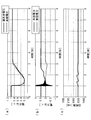
- A Trends of system voltage and interconnection point voltage in the case of rotation speed control according to the first embodiment,
- b Trends of active power and reactive power supplied from a generator,
- c Generator rotation It is the figure which showed an example of the tendency of the number. It is an operation
- A Trends of system voltage and interconnection point voltage in the case of rotation speed control according to the third embodiment of the present invention, (b) Trends of active power and reactive power supplied from a generator, (c) It is a figure showing an example of a tendency of generator number of rotations.
- A Trends of grid voltage and interconnection point voltage in the case of conventional control, (b) Trends of active power and reactive power supplied from a generator, (c) Trends of generator rotational speed is there.
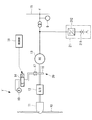
- FIG. 1 is a block diagram showing a schematic configuration of a wind turbine 1 according to the present embodiment.
- the wind turbine generator 10 according to this embodiment includes a wind turbine blade 10, a wind turbine rotor hub (rotor) 11, a gear 12, a generator (induction generator) 13, a solenoid valve 14, a hydraulic pump 19, A voltmeter 9, a control unit (control means) 18, and a brake 20 are provided, and are connected (connected) to a power system 15 at an interconnection point Y.
- a plurality of wind turbine blades 10 are radially attached to the wind turbine rotor hub 11.
- a generator 13 is connected to the main shaft of the wind turbine rotor hub 11 via a gear 12 having a predetermined gear ratio, and is mechanically connected and integrally rotatable.
- the wind turbine blade 10 receives the wind energy, rotates with the wind turbine rotor hub 11, and drives the generator 13 to generate electric power, thereby converting the wind energy into electric energy.
- the generator 13 is a fixed speed type induction generator, and is, for example, a cage type induction generator.
- a voltmeter 9 is provided in the vicinity of an interconnection point Y between the wind turbine 1 and the electric power system 15. The voltmeter 9 measures the voltage at the interconnection point Y and outputs the measurement result to the control unit 18.
- the hydraulic pump 19 is adapted to deliver a working fluid (for example, a hydraulic fluid) in a tank (not shown), and the delivered working fluid is fed to the solenoid valve 14.
- the solenoid valve 14 is controlled by the controller 18 to turn on and off.
- the solenoid valve 14 actuates the brake 20 by the working fluid fed from the hydraulic pump 19 when in the on state, and releases the actuation of the brake 20 when in the off state.
- the brake 20 is connected to the hydraulic pump 19 via a solenoid valve 14.
- the brake 20 includes a brake disc 16 and a brake caliper 17.
- the brake disc 16 is mechanically connected to rotate integrally with the wind turbine rotor hub 11.
- the brake caliper 17 has a brake pad (not shown) on the surface facing the brake disc 16, and the working fluid supplied when the solenoid valve 14 is turned on causes the brake caliper 17 to transmit the brake disc 16 via the brake pad. It pinches and brakes the rotation of the brake disc 16. By braking the rotation of the brake disk 16 in this manner, the rotation of the wind turbine rotor hub 11 is adjusted or the rotation is stopped.
- the control unit 18 determines that the low voltage event has occurred when the voltage of the electric power system 15 becomes smaller than the first threshold, and the rotation speed of the generator 13 can be obtained at the synchronous speed and the rated output.
- the brake 20 is controlled to have a rotational speed between the rotational speed and the rotational speed.
- Low voltage events include, for example, the short voltage drop patterns required by LVRT.
- the generator speed is preferably approximately synchronous.
- the control unit 18 determines whether or not the voltage measurement result obtained from the voltmeter 9 is smaller than the first threshold, and if smaller than the first threshold, it is determined that the low voltage event has occurred. Do. Further, the control unit 18 controls the number of rotations of the generator 13 by controlling the brake 20 on and off. Specifically, the control unit 18 outputs an on / off control signal of the solenoid valve 14 to the solenoid valve 14 and performs on / off control of the brake 20 by switching the on / off state of the solenoid valve 14.
- the control unit 18 functions as, for example, a CPU (central processing unit) that executes various arithmetic processing, an auxiliary storage device such as a ROM (Read Only Memory) that is a read only memory that stores basic programs and the like, and a work area of the CPU.
- the computer system includes a main storage device such as a random access memory (RAM), which is a readable and writable memory, and a storage device for storing programs and various data.
- RAM random access memory
- a control program of the wind turbine generator is stored in the ROM of the control unit 18.
- a series of processing steps for realizing various functions to be described later are realized by the CPU reading an operation program to a RAM or the like and executing information processing / operation processing.
- FIG. 2 is a diagram showing an example of the tendency of the voltage, the electric power, and the rotational speed of the generator when the brake control is performed.
- FIG. 3 is an operation flow showing a process of brake control according to the rotational speed control of the wind turbine 1 according to the present embodiment.
- the synchronous speed of the generator 13 shall be 1500 rpm, and the case where the slip which can obtain a rated output is 2% is mentioned as an example, and is demonstrated.
- the voltage value of the connection point Y between the wind turbine 1 and the power system 15 is acquired (step SA1). It is determined whether or not the voltage value at the interconnection point Y is smaller than a first threshold (for example, 0.6 pu) (step SA2), and if it is not smaller than the first threshold, the process returns to step SA1 and repeats the process.
- a first threshold for example, 0.6 pu
- step SA7 When the generator rotational speed becomes larger than the third threshold (e.g., around 1.4 seconds in FIG. 2), the brake control is turned on, and the controller 18 outputs an on-off control signal to the solenoid valve 14. An on signal is output (step SA7), and the process returns to step SA1 to repeat the process.
- the solenoid valve 14 controls the valve opening degree to the on state based on the acquired on signal, and operates the brake 20 by the working fluid from the hydraulic pump 19.
- the solenoid valve 14 When the solenoid valve 14 is turned on and the brake 20 is driven, the brake caliper 17 holds the brake disc 16 rotating together with the wind turbine rotor hub 11, and the friction force between the brake caliper 17 and the brake disc 16 The rotation of the brake disc 16 is decelerated.
- step SA1 the brake control is performed when the generator rotational speed increases to 1530 rpm, the rotational speed decreases thereafter. Then, the process returns to step SA1 to repeat the process.
- the brake control is performed twice at around 1.4 seconds and around 2.0 seconds, and the generator rotational speed becomes approximately the synchronous speed. Since control is performed as described above, the reactive power consumed by the generator 13 is reduced as compared with the reactive power consumption shown in FIG. 7B, as shown by the dotted line in FIG. 2B.
- step SA4 determines whether the voltage at the interconnection point Y is smaller than the first threshold, but also determines whether it is larger than the second threshold (e.g., 0.8 pu) larger than the first threshold. It is determined (step SA4). If it is not larger than the second threshold value, the process returns to step SA1 and the present process is repeated. If the voltage value at the connection point Y is larger than the second threshold value, the brake control is turned off (step SA5), and the process ends.
- the second threshold e.g. 0.8 pu
- step SA8 even if the voltage at the interconnection point Y is smaller than the first threshold, if the generator rotational speed is smaller than the fourth threshold (step SA8), the brake control is turned off (step SA9). It returns to step SA1. Further, as shown in FIG. 2A, as in the present embodiment, by controlling the generator rotational speed by brake control and suppressing consumption of reactive power, the voltage value of the interconnection point voltage is Accurately follow the voltage value of voltage.
- the control unit 18 for controlling the brake 20 for braking the rotation of the wind turbine rotor hub 11 rotated by the wind power is the power system 15. It is determined that a low voltage event has occurred when the voltage of V becomes smaller than the first threshold, and the number of rotations of the rotor is the number of rotations between the synchronous speed and the number of rotations of the generator 13 at which rated output can be obtained Control the brake 20 in the same manner. As described above, since the rotational speed of the generator 13 is controlled using the brake 20 that brakes the rotation of the wind turbine rotor hub 11 provided on the shaft of the wind power generation device 1, invalidity occurs due to the generator rotational speed rising.
- the pitch angle is on the feather side in the case of controlling the number of revolutions according to the pitch angle of the wind turbine blade 10, in the present invention, the number of revolutions is not controlled by the pitch angle. There is no sinking of active power.
- the active power returns to the rated operation around 5 seconds as shown by the solid line in FIG.
- the active power returns to the rated operation about 0.5 seconds after the power system is restored near the time 2.8 seconds.
- the time required for the voltage recovery can be shortened (about 2 seconds in the above example) as compared to the case where the brake control is not performed.
- the present invention may be applied to a wind turbine generator having a stall control mechanism that does not have a pitch control mechanism.
- the present embodiment differs from the first embodiment in that the control unit of the wind turbine generator according to the first embodiment performs feedback control of the brake, instead of performing on / off control of the brake.
- the control unit of the wind turbine generator according to the first embodiment performs feedback control of the brake, instead of performing on / off control of the brake.
- description is abbreviate
- the control unit performs feedback control (e.g., PID control) so that the rotational speed of the generator matches the target rotational speed set in the range of the rotational speed between the synchronous speed and the rotational speed of the generator from which the rated output can be obtained.
- PID control e.g., PID control
- a servo valve is used instead of the solenoid valve 14 of FIG. 1 as a structure of a wind power generator.
- the generator rotational speed information is fed back to the control unit, and the PID controller provided in the control unit performs proportional control (P control), integral control (I control) and differential control (P control) on the servo valve.
- a control amount servo valve opening command signal
- D control digital control
- the control unit outputs the generated servo valve opening degree command signal to the servo valve, and adjusts the valve opening degree of the servo valve, thereby gradually stepping up the flow rate of the working fluid to be circulated from the hydraulic pump side to the brake side. adjust.
- the generator rotational speed can be accurately controlled by performing feedback control so that the generator rotational speed matches the target rotational speed, the case where reactive power consumption suppression and active power recovery are controlled by on / off control You can do it effectively compared to.
- the third embodiment of the present invention will be described below.
- the schematic configuration of the wind turbine generator according to the third embodiment will be described with reference to FIGS. 4 to 6.
- the present embodiment in addition to the configuration of the wind turbine generator according to the first embodiment, includes a power adjustment unit (power adjustment unit) 21 as shown in FIG. It differs from the second embodiment.
- a power adjustment unit power adjustment unit 21 as shown in FIG. It differs from the second embodiment.
- about wind power generation control device 1 'of this embodiment explanation is omitted about a point which is common in a 1st embodiment and a 2nd embodiment, and a different point is mainly explained.
- the wind turbine generator 1 ′ includes a power adjustment unit 21 between the generator 13 and the power system 15.
- the power adjustment unit 21 determines that the system is restored when the voltage value of the power system 15 becomes larger than the second threshold after the occurrence of the low voltage event of the power system 15, and the output power value of the wind turbine 1 ' But adjust the power to a power value just before the low voltage event occurs.
- the power adjustment unit 21 includes an AC-DC converter 212 and a power storage device 211 that stores power.
- the AC-DC converter 212 is an AC-DC converter that converts AC and DC, and for example, in order to supply the active power determined by the control unit 18 to the power system 15, it is stored in the power storage device 211 The direct current power is converted into alternating current power, and the converted alternating current power is output to the power system 15.
- the power storage device 211 is, for example, a secondary battery such as a lithium ion battery, a lead storage battery, a sodium sulfur battery, or a redox flow battery. Further, the power storage device 21 is not limited to supplying power to the power system 15 side, and may be used as a power supply source for supplying power to the control unit 18.
- the control unit 18 determines whether the active power value at the connection point Y is a value immediately before the occurrence of the low voltage event. For example, after system restoration, the output may decrease due to an event such as a decrease in wind speed, and the active power value may be smaller than the power value immediately before the low voltage event occurs, as indicated by X in FIG. . In such a case, the control unit 18 causes the power adjustment unit 21 to supply power to the power system 15 side, and boosts the active power value to a value immediately before the occurrence of the low voltage event. As a result, as shown in FIG. 6B, the fall of the active power does not occur after the power recovery.
Landscapes
- Engineering & Computer Science (AREA)
- Power Engineering (AREA)
- Life Sciences & Earth Sciences (AREA)
- Sustainable Development (AREA)
- Sustainable Energy (AREA)
- Chemical & Material Sciences (AREA)
- Combustion & Propulsion (AREA)
- Mechanical Engineering (AREA)
- General Engineering & Computer Science (AREA)
- Wind Motors (AREA)
- Control Of Eletrric Generators (AREA)
- Supply And Distribution Of Alternating Current (AREA)
Abstract
電力系統の低電圧事象の発生後の電力系統の復帰時における有効電力の落ち込み及び無効電力消費を抑制する。風力によって回転する風車ロータハブ(11)と、該風車ロータハブ(11)の回転により駆動される固定速方式の誘導発電機(13)と、前記風車ロータハブ(11)の回転を制動させるブレーキ(20)とを備え、電力系統(15)に連系される風力発電装置(1)が、前記電力系統(15)の電圧が第1閾値より小さくなった場合に低電圧事象が発生したと判断し、前記誘導発電機(13)の回転数を、同期速度と定格出力が得られる前記誘導発電機(13)の回転数との間の回転数となるよう前記ブレーキ(20)を制御する制御部(18)を具備する。
Description
本発明は、風力発電装置及び方法並びにプログラムに関するものである。
近年、風力発電設備の電力系統連系要件のガイドラインが整備されており、設置される風力発電装置は、連系要件に適合させる必要がある。また、電力系統の事故発生に伴い、短時間の電力系統の低電圧事象が発生した場合に、風力発電装置を電力系統側から解列させずに、電力系統に及ぼす影響を最小限に抑える運用、即ち、LVRT(Low Voltage Ride Through)に対応する機能が要求されている。
例えば、電力系統側の事故発生に伴って電力系統の電圧が低下する低電圧事象が発生すると、風力発電装置の発電機は、負荷がなくなることにより回転数が上昇するが、所定量以上回転数が上昇すると風力発電装置が故障するので、所定の回転速度に制御し故障を防ぐ技術が検討されている。
下記特許文献1には、電力系統の事故発生時には、風車ブレードのピッチ角を制御して事故に伴う発電機の過回転を防止し、また、電力系統の電圧値が事故前の状態に復帰した場合には、ピッチ角を制御して回転速度を運転可能領域内に制御し、運転再開までの時間を短縮する技術が提案されている。
下記特許文献1には、電力系統の事故発生時には、風車ブレードのピッチ角を制御して事故に伴う発電機の過回転を防止し、また、電力系統の電圧値が事故前の状態に復帰した場合には、ピッチ角を制御して回転速度を運転可能領域内に制御し、運転再開までの時間を短縮する技術が提案されている。
また、例えば、電力系統の電圧が低下した状態から回復すると、そのときのすべりに応じて大きな電流が流れるとともに大きなトルクが発生し、機器への荷重が大きくかかるので、発電機の回転数が同期回転数またはそれ以上となるように風車ブレードのピッチ角を制御して、コンバータ及びインバータの制御が再開されたときに生じる大きなトルク発生、或いは、反負荷トルクの発生を防止する技術が提案されている(下記特許文献2)。
しかしながら、上記特許文献1及び上記特許文献2の方法のようにピッチ角制御による回転数制御を行う場合には、電力系統の電圧値が事故前の状態に復帰した時点で、風車ブレードがフェザー側(風を逃がす側)にあるので、図7(b)実線で示されるように、有効電力値の落ち込みが生じるという問題があった。
また、電力系統の電圧値の復帰時において、過回転に起因して、固定速方式で誘導発電機を搭載している風力発電装置では誘導発電機が消費する無効電力が、図7(b)の点線で示されるように、多くなる。このような場合には、風力発電装置と電力系統との連系点の電圧は、電力系統側から見て結果的に低下することとなり、図7(a)の実線で示されるように、電力系統の電圧値(図7(a)の点線)まで上がりきらない。従来は、こうした無効電力消費を抑制する方法がなく、無効電力の消費を抑制することができないという問題点があった。さらに、風車ブレードのピッチ角制御による回転数の制御は、応答速度が遅いのでLVRTのような瞬時に発生する低電圧事象に対しては、不向きであった。
また、電力系統の電圧値の復帰時において、過回転に起因して、固定速方式で誘導発電機を搭載している風力発電装置では誘導発電機が消費する無効電力が、図7(b)の点線で示されるように、多くなる。このような場合には、風力発電装置と電力系統との連系点の電圧は、電力系統側から見て結果的に低下することとなり、図7(a)の実線で示されるように、電力系統の電圧値(図7(a)の点線)まで上がりきらない。従来は、こうした無効電力消費を抑制する方法がなく、無効電力の消費を抑制することができないという問題点があった。さらに、風車ブレードのピッチ角制御による回転数の制御は、応答速度が遅いのでLVRTのような瞬時に発生する低電圧事象に対しては、不向きであった。
本発明は、このような事情に鑑みてなされたものであって、電力系統の低電圧事象の発生後、電力系統の電圧値の復帰時における有効電力の落ち込み、及び無効電力消費を抑制できる風力発電装置及び方法並びにプログラムを提供することを目的とする。
本発明の第1の態様は、風力によって回転するロータと、前記ロータの回転により駆動される固定速方式の誘導発電機と、前記ロータの回転を制動させるブレーキとを備え、電力系統に連系される風力発電装置であって、前記電力系統の電圧が第1閾値より小さくなった場合に低電圧事象が発生したと判断し、前記誘導発電機の回転数を、同期速度と定格出力が得られる前記誘導発電機の回転数との間の回転数となるよう前記ブレーキを制御する制御手段を具備する風力発電装置である。
このような構成によれば、風力によって回転するロータの回転を制動させるブレーキを制御する制御手段は、電力系統の電圧が第1閾値より小さくなった場合に低電圧事象が発生したと判断して、ロータの回転数を、同期速度と定格出力が得られる誘導発電機の回転数との間の回転数となるようにブレーキを制御する。
このように、誘導発電機の回転数は、風力発電装置の軸に設けられるロータの回転を制動させるブレーキを用いて制御するので、発電機回転数が上昇することにより発生する無効電力の消費を抑制でき、電力系統と風力発電装置との連系点における電圧の速やかな復帰に寄与できる。また、風車ブレードのピッチ角によって回転数制御する場合にはピッチ角をフェザー側にしているが、本発明ではピッチ角による回転数制御をしていないので、電力系統の電圧が復帰した場合における有効電力の落ち込みを低減できる。さらに、発電機回転数を風車ブレードのピッチ角制御によって制御する場合と比較して、電力系統が復帰した場合において、連系点における電圧復帰にかかる時間を短縮することができる。制御手段によって制御される発電機回転数は、好ましくは略同期速度である。
このように、誘導発電機の回転数は、風力発電装置の軸に設けられるロータの回転を制動させるブレーキを用いて制御するので、発電機回転数が上昇することにより発生する無効電力の消費を抑制でき、電力系統と風力発電装置との連系点における電圧の速やかな復帰に寄与できる。また、風車ブレードのピッチ角によって回転数制御する場合にはピッチ角をフェザー側にしているが、本発明ではピッチ角による回転数制御をしていないので、電力系統の電圧が復帰した場合における有効電力の落ち込みを低減できる。さらに、発電機回転数を風車ブレードのピッチ角制御によって制御する場合と比較して、電力系統が復帰した場合において、連系点における電圧復帰にかかる時間を短縮することができる。制御手段によって制御される発電機回転数は、好ましくは略同期速度である。
上記風力発電装置の前記制御手段は、前記ブレーキをオンオフ制御することにより前記誘導発電機の回転数を制御することとしてもよい。
オンオフ制御により簡便に発電機回転数を制御できる。
オンオフ制御により簡便に発電機回転数を制御できる。
上記風力発電装置の前記制御手段は、同期速度と定格出力が得られる前記誘導発電機の回転数との間の回転数の範囲で設定された目標回転数に、前記誘導発電機の回転数が一致するようにフィードバック制御することとしてもよい。
発電機回転数を目標回転数に一致するようにフィードバック制御することにより発電機回転数を精度よく制御できるので、オンオフ制御する場合と比較して、無効電力消費の抑制及び有効電力の復帰を効果的に行える。
発電機回転数を目標回転数に一致するようにフィードバック制御することにより発電機回転数を精度よく制御できるので、オンオフ制御する場合と比較して、無効電力消費の抑制及び有効電力の復帰を効果的に行える。
上記風力発電装置は、前記誘導発電機と前記電力系統との間に電力調整手段を具備し、前記電力調整手段は、前記電力系統の前記低電圧事象が発生した後に、前記電力系統の電圧値が第2閾値より大きくなった場合に系統復帰したと判断し、当該風力発電装置の出力電力値が、前記低電圧事象が発生する直前の電力値となるように電力調整することとしてもよい。
例えば、系統復帰後において風速の低下が生じた場合であっても、低電圧事象直前の電力値となるように電力調整される。或いは、低電圧事象の後、電圧復帰し、その後に風速が弱くなる事態が発生すると、電力系統側に供給される電力は減少増大減少と、不安定な状態となるが、電力調整手段により電力調整されることにより電力系統側に安定した出力が供給される。
また、低電圧事象後の電圧復帰を加速するために、電力調整手段により無効電力を供給することとしてもよい。
また、低電圧事象後の電圧復帰を加速するために、電力調整手段により無効電力を供給することとしてもよい。
上記風力発電装置の前記電力調整手段は、蓄電できる電力貯蔵装置であることとしてもよい。
電力貯蔵装置によって、電力調整を簡便に行うことができる。また、電力貯蔵装置は、例えば、リチウムイオン電池、鉛蓄電池、ナトリウム硫黄電池、レドックスフロー電池等の二次電池である。
電力貯蔵装置によって、電力調整を簡便に行うことができる。また、電力貯蔵装置は、例えば、リチウムイオン電池、鉛蓄電池、ナトリウム硫黄電池、レドックスフロー電池等の二次電池である。
上記風力発電装置の前記電力貯蔵装置は、前記制御手段に電力を供給することとしてもよい。
電力貯蔵装置に蓄電された電力を制御手段の電源として使用でき、電力を有効活用することができる。
電力貯蔵装置に蓄電された電力を制御手段の電源として使用でき、電力を有効活用することができる。
本発明の第2の態様は、風力によって回転するロータと、前記ロータの回転により駆動される固定速方式の誘導発電機と、前記ロータの回転を制動させるブレーキとを備え、電力系統に連系される風力発電装置の制御方法であって、前記電力系統の電圧が第1閾値より小さくなった場合に低電圧事象が発生したと判断し、前記誘導発電機の回転数を、同期速度と定格出力が得られる前記誘導発電機の回転数との間の回転数となるよう前記ブレーキを制御する風力発電装置の制御方法である。
本発明の第3の態様は、風力によって回転するロータと、前記ロータの回転により駆動される固定速方式の誘導発電機と、前記ロータの回転を制動させるブレーキとを備え、電力系統に連系される風力発電装置の制御プログラムであって、前記電力系統の電圧が第1閾値より小さくなった場合に低電圧事象が発生したと判断し、前記誘導発電機の回転数を、同期速度と定格出力が得られる前記誘導発電機の回転数との間の回転数となるよう前記ブレーキを制御することをコンピュータに実行させるための風力発電装置の制御プログラムである。
本発明は、電力系統の低電圧事象の発生後、電力系統の電圧値の復帰時における有効電力の落ち込み、及び無効電力消費を抑制できるという効果を奏する。
第1の実施形態
以下に、本発明に係る風力発電装置及び方法並びにプログラムの一実施形態について、図面を参照して説明する。
以下に、本発明に係る風力発電装置及び方法並びにプログラムの一実施形態について、図面を参照して説明する。
図1は、本実施形態に係る風力発電装置1の概略構成を示したブロック図である。図1に示されるように、本実施形態に係る風力発電装置1は、風車ブレード10、風車ロータハブ(ロータ)11、ギア12、発電機(誘導発電機)13、電磁弁14、油圧ポンプ19、電圧計9、制御部(制御手段)18、及びブレーキ20を備えており、連系点Yにおいて電力系統15と接続(連系)されている。
風車ブレード10は、風車ロータハブ11に複数枚が放射状に取り付けられている。風車ロータハブ11の主軸には、所定の変速比を持ったギア12を介して発電機13が接続されており、機械的に連結され、一体に回転可能となっている。
風車ブレード10は、風車ロータハブ11に複数枚が放射状に取り付けられている。風車ロータハブ11の主軸には、所定の変速比を持ったギア12を介して発電機13が接続されており、機械的に連結され、一体に回転可能となっている。
したがって、風車ブレード10が風力エネルギーを受けて風車ロータハブ11と共に回転し、発電機13を駆動して発電することにより風力エネルギーを電気エネルギーに変換するようになっている。発電機13は、固定速方式の誘導発電機であり、例えば、かご型誘導発電機である。
風力発電装置1と電力系統15との連系点Yの近傍には、電圧計9が設けられている。電圧計9は、連系点Yの電圧を計測し、計測結果を制御部18に出力する。
風力発電装置1と電力系統15との連系点Yの近傍には、電圧計9が設けられている。電圧計9は、連系点Yの電圧を計測し、計測結果を制御部18に出力する。
油圧ポンプ19は、図示しないタンク内の作動流体(例えば、作動油)が送り出されるようになっており、送り出された作動流体は、電磁弁14に送り込まれる。
電磁弁14は、制御部18によってオンオフが制御される。電磁弁14は、オン状態である場合に、油圧ポンプ19から送り込まれた作動流体によりブレーキ20を作動させ、オフ状態である場合に、ブレーキ20の作動を解除する。
電磁弁14は、制御部18によってオンオフが制御される。電磁弁14は、オン状態である場合に、油圧ポンプ19から送り込まれた作動流体によりブレーキ20を作動させ、オフ状態である場合に、ブレーキ20の作動を解除する。
ギア12と発電機13との間には、風車ロータハブ11の回転を制動させるブレーキ20が設けられている。ブレーキ20は、電磁弁14を介して油圧ポンプ19と接続されている。
ブレーキ20は、ブレーキディスク16とブレーキキャリパ17とを備えている。ブレーキディスク16は、風車ロータハブ11と一体に回転するように機械的に連結されている。ブレーキキャリパ17は、ブレーキディスク16と対峙する面に図示しないブレーキパッドを備え、電磁弁14がオン状態となることで供給される作動流体によって、ブレーキキャリパ17がブレーキパッドを介してブレーキディスク16を挟み込み、ブレーキディスク16の回転を制動する。このようにブレーキディスク16の回転を制動することで、風車ロータハブ11の回転を調整させたり、回転を停止させたりする。
ブレーキ20は、ブレーキディスク16とブレーキキャリパ17とを備えている。ブレーキディスク16は、風車ロータハブ11と一体に回転するように機械的に連結されている。ブレーキキャリパ17は、ブレーキディスク16と対峙する面に図示しないブレーキパッドを備え、電磁弁14がオン状態となることで供給される作動流体によって、ブレーキキャリパ17がブレーキパッドを介してブレーキディスク16を挟み込み、ブレーキディスク16の回転を制動する。このようにブレーキディスク16の回転を制動することで、風車ロータハブ11の回転を調整させたり、回転を停止させたりする。
制御部18は、電力系統15の電圧が第1閾値より小さくなった場合に低電圧事象が発生したと判断し、発電機13の回転数を、同期速度と定格出力が得られる発電機13の回転数との間の回転数となるようブレーキ20を制御する。低電圧事象は、例えば、LVRTで要求される短時間の電圧低下パターンを含む。発電機回転数は、好ましくは略同期速度である。具体的には、制御部18は、電圧計9から取得した電圧計測結果が第1閾値より小さいか否かを判定し、第1閾値より小さい場合には、低電圧事象が発生したことと判定する。
また、制御部18は、ブレーキ20をオンオフ制御することにより発電機13の回転数を制御する。具体的には、制御部18は、電磁弁14に対して、電磁弁14のオンオフ制御信号を出力し、電磁弁14のオンオフ状態の切り替えによって、ブレーキ20をオンオフ制御する。
また、制御部18は、ブレーキ20をオンオフ制御することにより発電機13の回転数を制御する。具体的には、制御部18は、電磁弁14に対して、電磁弁14のオンオフ制御信号を出力し、電磁弁14のオンオフ状態の切り替えによって、ブレーキ20をオンオフ制御する。
制御部18は、例えば、各種演算処理を実行するCPU(中央演算装置)、基本プログラム等を記憶する読み出し専用のメモリであるROM(Read Only Memory)等の補助記憶装置、CPUの作業領域として機能する読み書き自在のメモリであるRAM(Random Access Memory)等の主記憶装置、及びプログラムや各種データを記憶する記憶装置を有するコンピュータシステムを備えている。制御部18のROMには、例えば、風力発電装置の制御プログラムが格納されている。後述の各種機能を実現するための一連の処理過程は、CPUが演算プログラムをRAM等に読み出して、情報の加工・演算処理を実行することにより実現される。
図2は、ブレーキ制御をした場合の発電機の電圧、電力、回転数の傾向の一例を示す図である。図3は、本実施形態にかかる風力発電装置1の回転数制御にかかるブレーキ制御の過程を示す動作フローである。以下に、図2及び図3を用いて、本実施形態に係る風力発電装置1の作用について説明する。ここでは、発電機13の同期速度は1500rpmとし、定格出力が得られるすべりが2%である場合を例に挙げて説明する。
制御装置18において、風力発電装置1と電力系統15との連系点Yの電圧値が取得される(ステップSA1)。連系点Yの電圧値が第1閾値(例えば、0.6pu)より小さいか否かが判定され(ステップSA2)、第1閾値より小さくない場合にはステップSA1に戻り、処理を繰り返す。
制御装置18において、風力発電装置1と電力系統15との連系点Yの電圧値が取得される(ステップSA1)。連系点Yの電圧値が第1閾値(例えば、0.6pu)より小さいか否かが判定され(ステップSA2)、第1閾値より小さくない場合にはステップSA1に戻り、処理を繰り返す。
図2の時刻1秒の時点で、電力系統15側に低電圧事象が発生し、連系点Yの電圧値が第1閾値より小さくなった場合には、発電機13の回転数の情報を取得し(ステップSA3)、発電機回転数が第3閾値(例えば、1530rpm(=1500rpm+1500rpm×2%))より大きいか否かが判定される(ステップSA6)。発電機回転数が第3閾値より大きくない場合にはステップSA1に戻り、処理を繰り返す。
発電機回転数が第3閾値より大きくなった場合(例えば、図2の時刻1.4秒付近)には、ブレーキ制御がオン状態となり、制御装置18から電磁弁14に対してオンオフ制御信号のオン信号が出力され(ステップSA7)、ステップSA1に戻り、処理を繰り返す。電磁弁14は、取得したオン信号に基づいて弁開度をオン状態に制御し、油圧ポンプ19からの作動流体によりブレーキ20を作動させる。電磁弁14がオン状態となりブレーキ20が駆動される場合には、風車ロータハブ11と共に回転しているブレーキディスク16をブレーキキャリパ17が挟み込み、ブレーキキャリパ17とブレーキディスク16との間の摩擦力により、ブレーキディスク16の回転が減速される。
そうすると、図2(c)に示されるように、発電機回転数が1530rpmまで上がった時点でブレーキ制御されるので、その後回転数が下がる。そしてステップSA1に戻り処理を繰り返す。本実施形態では、図2(c)に示されるように、時刻1.4秒付近と2.0秒付近とにおいてブレーキ制御が2回行われており、発電機回転数が略同期速度になるように制御されているので、図2(b)の点線で示されるように発電機13が消費する無効電力が、図7(b)で示される無効電力消費量より低減されている。
その後、電力系統の電圧が復帰してくると、図2(a)に示されるように、徐々に系統電圧が上昇し、連系点電圧も上昇する。
また、制御部18は、連系点Yの電圧が第1閾値より小さいか否かを判定するだけでなく、第1閾値より大きい第2閾値(例えば、0.8pu)より大きいか否かが判定される(ステップSA4)。第2閾値より大きくない場合にはステップSA1に戻り、本処理を繰り返す。連系点Yの電圧値が、第2閾値より大きい場合には、ブレーキ制御がオフ状態とされ(ステップSA5)、本処理を終了する。
また、制御部18は、連系点Yの電圧が第1閾値より小さいか否かを判定するだけでなく、第1閾値より大きい第2閾値(例えば、0.8pu)より大きいか否かが判定される(ステップSA4)。第2閾値より大きくない場合にはステップSA1に戻り、本処理を繰り返す。連系点Yの電圧値が、第2閾値より大きい場合には、ブレーキ制御がオフ状態とされ(ステップSA5)、本処理を終了する。
ブレーキ制御がオフ状態とされる場合には、制御部18から電磁弁14に対し、オンオフ制御信号のオフ信号が出力され、電磁弁14の弁開度はオフ状態とされる。これにより、風車ブレード10は、ブレーキ制御されることなく運転し、また、低電圧事象が発生した時に回転数制御のためのピッチ角制御が行われていないので、図2(b)の実線で示されるように、電圧復帰後に有効電力が落ち込まない。
また、連系点Yの電圧が第1閾値より小さい場合であっても、発電機回転数が第4閾値より小さい場合には(ステップSA8)、ブレーキ制御がオフ状態とされ(ステップSA9)、ステップSA1に戻る。
また、図2(a)に示されるように、本実施形態のように、ブレーキ制御によって発電機回転数を制御し、無効電力の消費を抑制することにより、連系点電圧の電圧値が系統電圧の電圧値に精度よく追従する。
また、図2(a)に示されるように、本実施形態のように、ブレーキ制御によって発電機回転数を制御し、無効電力の消費を抑制することにより、連系点電圧の電圧値が系統電圧の電圧値に精度よく追従する。
以上説明してきたように、本実施形態に係る風力発電装置1及びその方法並びにプログラムによれば、風力によって回転する風車ロータハブ11の回転を制動させるブレーキ20を制御する制御部18は、電力系統15の電圧が第1閾値より小さくなった場合に低電圧事象が発生したと判断し、ロータの回転数を、同期速度と定格出力が得られる発電機13の回転数との間の回転数となるようにブレーキ20を制御する。
このように、発電機13の回転数は、風力発電装置1の軸に設けられる風車ロータハブ11の回転を制動させるブレーキ20を用いて制御するので、発電機回転数が上昇することにより発生する無効電力の消費を抑制でき、連系点Yにおける電圧の速やかな復帰に寄与できる。また、風車ブレード10のピッチ角によって回転数制御する場合にはピッチ角をフェザー側にしているが、本発明ではピッチ角による回転数制御をしていないので、電力系統15の電圧が復帰した場合に、有効電力が落ち込まない。
このように、発電機13の回転数は、風力発電装置1の軸に設けられる風車ロータハブ11の回転を制動させるブレーキ20を用いて制御するので、発電機回転数が上昇することにより発生する無効電力の消費を抑制でき、連系点Yにおける電圧の速やかな復帰に寄与できる。また、風車ブレード10のピッチ角によって回転数制御する場合にはピッチ角をフェザー側にしているが、本発明ではピッチ角による回転数制御をしていないので、電力系統15の電圧が復帰した場合に、有効電力が落ち込まない。
さらに、発電機回転数を風車ブレード10のピッチ角制御によって制御する場合には、図7(b)の実線で示されるように有効電力は時刻5秒付近で定格運転に復帰しているが、本発明では図2(b)の実線で示されるように有効電力は、時刻2.8秒付近で電力系統の復帰がされた後、約0.5秒経過後に定格運転に復帰している。このように、ブレーキ制御を行わない場合と比較して、本発明では、電圧復帰にかかる時間を短縮(上記例では、約2秒)できる。
また、本発明は、ピッチ制御機構を持たないストール制御機構を有する風力発電装置に適用してもよい。
第2の実施形態
以下、本発明の第2の実施形態について説明する。本実施形態は、第1の実施形態に係る風力発電装置の制御部が、ブレーキをオンオフ制御していたことに代えて、ブレーキをフィードバック制御する点で第1の実施形態と異なる。本実施形態の風力発電装置について、第1の実施形態と共通する点については説明を省略し、異なる点について主に説明する。
以下、本発明の第2の実施形態について説明する。本実施形態は、第1の実施形態に係る風力発電装置の制御部が、ブレーキをオンオフ制御していたことに代えて、ブレーキをフィードバック制御する点で第1の実施形態と異なる。本実施形態の風力発電装置について、第1の実施形態と共通する点については説明を省略し、異なる点について主に説明する。
制御部は、同期速度と定格出力が得られる発電機の回転数との間の回転数の範囲で設定された目標回転数に、発電機の回転数が一致するようにフィードバック制御(例えば、PID制御、PI制御)する。例えば、風力発電装置の構成として図1の電磁弁14に代えてサーボ弁を用いる。PID制御する場合には、発電機回転数の情報を制御部にフィードバックし、制御部に設けられるPID制御器により、サーボ弁に対する比例制御(P制御)、積分制御(I制御)および微分制御(D制御)に基づく制御量(サーボ弁の開度指令信号)を生成する。制御部は、生成されたサーボ弁の開度指令信号をサーボ弁に出力し、サーボ弁の弁開度を調整することにより、油圧ポンプ側からブレーキ側に流通させる作動流体の流量を段階的に調整する。
このように、発電機回転数を目標回転数に一致するようにフィードバック制御することにより発電機回転数を精度よく制御できるので、無効電力消費の抑制及び有効電力の復帰をオンオフ制御によって制御する場合と比較して、効果的に行える。
このように、発電機回転数を目標回転数に一致するようにフィードバック制御することにより発電機回転数を精度よく制御できるので、無効電力消費の抑制及び有効電力の復帰をオンオフ制御によって制御する場合と比較して、効果的に行える。
第3の実施形態
以下、本発明の第3の実施形態について説明する。本第3の実施形態に係る風力発電装置の概略構成は、図4から図6を用いて説明する。本実施形態は、第1の実施形態に係る風力発電装置の構成に加えて、図4に示されるように、電力調整部(電力調整手段)21を備える点で、第1の実施形態、第2の実施形態と異なる。本実施形態の風力発電御装置1´について、第1の実施形態、第2の実施形態と共通する点については説明を省略し、異なる点について主に説明する。
以下、本発明の第3の実施形態について説明する。本第3の実施形態に係る風力発電装置の概略構成は、図4から図6を用いて説明する。本実施形態は、第1の実施形態に係る風力発電装置の構成に加えて、図4に示されるように、電力調整部(電力調整手段)21を備える点で、第1の実施形態、第2の実施形態と異なる。本実施形態の風力発電御装置1´について、第1の実施形態、第2の実施形態と共通する点については説明を省略し、異なる点について主に説明する。
図4に示されるように、風力発電装置1´は、発電機13と電力系統15との間に電力調整部21を備えている。
電力調整部21は、電力系統15の低電圧事象が発生した後に、電力系統15の電圧値が第2閾値より大きくなった場合に系統復帰したと判断し、風力発電装置1´の出力電力値が、低電圧事象が発生する直前の電力値となるように電力調整する。
電力調整部21は、電力系統15の低電圧事象が発生した後に、電力系統15の電圧値が第2閾値より大きくなった場合に系統復帰したと判断し、風力発電装置1´の出力電力値が、低電圧事象が発生する直前の電力値となるように電力調整する。
具体的には、電力調整部21は、交流直流変換器212と、蓄電する電力貯蔵装置211とを備えている。
交流直流変換器212は、交流と直流を変換する交流直流変換器であって、例えば、制御部18によって決定された有効電力を電力系統15に供給するには、電力貯蔵装置211に蓄電されている直流電力を交流電力に変換し、変換後の交流電力を電力系統15に出力する。
電力貯蔵装置211は、例えば、リチウムイオン電池、鉛蓄電池、ナトリウム硫黄電池、レドックスフロー電池等の二次電池である。また、電力貯蔵装置21は、電力系統15側に電力を供給することに限られず、制御部18に電力を供給する電力供給源として使用されることとしてもよい。
交流直流変換器212は、交流と直流を変換する交流直流変換器であって、例えば、制御部18によって決定された有効電力を電力系統15に供給するには、電力貯蔵装置211に蓄電されている直流電力を交流電力に変換し、変換後の交流電力を電力系統15に出力する。
電力貯蔵装置211は、例えば、リチウムイオン電池、鉛蓄電池、ナトリウム硫黄電池、レドックスフロー電池等の二次電池である。また、電力貯蔵装置21は、電力系統15側に電力を供給することに限られず、制御部18に電力を供給する電力供給源として使用されることとしてもよい。
制御部18は、ブレーキ20の制御をした後、連系点Yにおける有効電力値が低電圧事象が発生する直前の値になっているか否かを判定する。例えば、系統復帰の後、風速低下などの事象により出力が低下し、図5のXで示されるように、有効電力値が、低電圧事象が発生する直前の電力値よりも小さくなることがある。このような場合に、制御部18は、電力調整部21から電力系統15側に電力を供給させ、有効電力値を低電圧事象が発生する直前の値まで嵩上げする。これにより、図6(b)に示されるように、電力復帰の後、有効電力の落ち込みが発生しない。
このように、電力貯蔵装置211に蓄電された電力によって有効電力を補うことにより、風速変化などの事象が生じた場合であっても、安定した有効電力が電力系統15側に供給できる。
また、低電圧事象後の電圧復帰を加速するために、電力貯蔵装置211より無効電力を電力系統15側に供給することもできる。これにより、より電力系統電圧を安定化できる。
このように、電力貯蔵装置211に蓄電された電力によって有効電力を補うことにより、風速変化などの事象が生じた場合であっても、安定した有効電力が電力系統15側に供給できる。
また、低電圧事象後の電圧復帰を加速するために、電力貯蔵装置211より無効電力を電力系統15側に供給することもできる。これにより、より電力系統電圧を安定化できる。
1、1´ 風力発電装置
13 発電機(誘導発電機)
15 電力系統
16 ブレーキディスク
17 ブレーキキャリパ
18 制御部(制御手段)
20 ブレーキ
13 発電機(誘導発電機)
15 電力系統
16 ブレーキディスク
17 ブレーキキャリパ
18 制御部(制御手段)
20 ブレーキ
Claims (8)
- 風力によって回転するロータと、前記ロータの回転により駆動される固定速方式の誘導発電機と、前記ロータの回転を制動させるブレーキとを備え、電力系統に連系される風力発電装置であって、
前記電力系統の電圧が第1閾値より小さくなった場合に低電圧事象が発生したと判断し、前記誘導発電機の回転数を、同期速度と定格出力が得られる前記誘導発電機の回転数との間の回転数となるよう前記ブレーキを制御する制御手段を具備する風力発電装置。 - 前記制御手段は、前記ブレーキをオンオフ制御することにより前記誘導発電機の回転数を制御する請求項1に記載の風力発電装置。
- 前記制御手段は、同期速度と定格出力が得られる前記誘導発電機の回転数との間の回転数の範囲で設定された目標回転数に、前記誘導発電機の回転数が一致するようにフィードバック制御する請求項1に記載の風力発電装置。
- 前記誘導発電機と前記電力系統との間に電力調整手段を具備し、
前記電力調整手段は、前記電力系統の前記低電圧事象が発生した後に、前記電力系統の電圧値が第2閾値より大きくなった場合に系統復帰したと判断し、当該風力発電装置の出力電力値が、前記低電圧事象が発生する直前の電力値となるように電力調整する請求項1から請求項3のいずれかに記載の風力発電装置。 - 前記電力調整手段は、蓄電できる電力貯蔵装置である請求項4に記載の風力発電装置。
- 前記電力貯蔵装置は、前記制御手段に電力を供給する請求項5に記載の風力発電装置。
- 風力によって回転するロータと、前記ロータの回転により駆動される固定速方式の誘導発電機と、前記ロータの回転を制動させるブレーキとを備え、電力系統に連系される風力発電装置の制御方法であって、
前記電力系統の電圧が第1閾値より小さくなった場合に低電圧事象が発生したと判断し、前記誘導発電機の回転数を、同期速度と定格出力が得られる前記誘導発電機の回転数との間の回転数となるよう前記ブレーキを制御する風力発電装置の制御方法。 - 風力によって回転するロータと、前記ロータの回転により駆動される固定速方式の誘導発電機と、前記ロータの回転を制動させるブレーキとを備え、電力系統に連系される風力発電装置の制御プログラムであって、
前記電力系統の電圧が第1閾値より小さくなった場合に低電圧事象が発生したと判断し、前記誘導発電機の回転数を、同期速度と定格出力が得られる前記誘導発電機の回転数との間の回転数となるよう前記ブレーキを制御することをコンピュータに実行させるための風力発電装置の制御プログラム。
Applications Claiming Priority (2)
| Application Number | Priority Date | Filing Date | Title |
|---|---|---|---|
| JP2011-248826 | 2011-11-14 | ||
| JP2011248826A JP2013106437A (ja) | 2011-11-14 | 2011-11-14 | 風力発電装置及び方法並びにプログラム |
Publications (1)
| Publication Number | Publication Date |
|---|---|
| WO2013073559A1 true WO2013073559A1 (ja) | 2013-05-23 |
Family
ID=48429615
Family Applications (1)
| Application Number | Title | Priority Date | Filing Date |
|---|---|---|---|
| PCT/JP2012/079477 Ceased WO2013073559A1 (ja) | 2011-11-14 | 2012-11-14 | 風力発電装置及び方法並びにプログラム |
Country Status (2)
| Country | Link |
|---|---|
| JP (1) | JP2013106437A (ja) |
| WO (1) | WO2013073559A1 (ja) |
Cited By (3)
| Publication number | Priority date | Publication date | Assignee | Title |
|---|---|---|---|---|
| CN110529336A (zh) * | 2019-09-06 | 2019-12-03 | 国电联合动力技术有限公司 | 一种风力发电机组有功功率快速调节的方法和系统 |
| CN113381438A (zh) * | 2020-03-10 | 2021-09-10 | 北京金风科创风电设备有限公司 | 风电机组的降功率控制方法和装置 |
| CN114421834A (zh) * | 2021-12-04 | 2022-04-29 | 中船动力研究院有限公司 | 一种发电机调速方法、系统、装置,及存储介质 |
Families Citing this family (4)
| Publication number | Priority date | Publication date | Assignee | Title |
|---|---|---|---|---|
| KR101422775B1 (ko) | 2013-05-31 | 2014-07-24 | 삼성중공업 주식회사 | 기어 제어형 풍력 발전 시스템 및 그 운영방법 |
| CN105545590B (zh) * | 2015-12-19 | 2018-03-20 | 湘电风能有限公司 | 一种风力发电机组的控制方法 |
| KR102102774B1 (ko) * | 2020-01-23 | 2020-04-22 | 에스씨씨 주식회사 | 발전성능을 향상시킨 타워형 풍력발전기 |
| CN113048017B (zh) * | 2021-04-02 | 2022-04-26 | 国网湖南省电力有限公司 | 基于内模控制的风电机组有功功率控制优化方法及系统 |
Citations (4)
| Publication number | Priority date | Publication date | Assignee | Title |
|---|---|---|---|---|
| JP2003042054A (ja) * | 2001-07-27 | 2003-02-13 | Ishikawajima Harima Heavy Ind Co Ltd | 風力発電装置及びその同期速度切替方法 |
| JP2008301584A (ja) * | 2007-05-30 | 2008-12-11 | Hitachi Ltd | 風力発電システムおよび電力変換器の制御方法 |
| JP2009261076A (ja) * | 2008-04-15 | 2009-11-05 | Hitachi Engineering & Services Co Ltd | 風力発電所 |
| WO2010095248A1 (ja) * | 2009-02-20 | 2010-08-26 | 三菱重工業株式会社 | 風力発電装置及びその制御方法 |
-
2011
- 2011-11-14 JP JP2011248826A patent/JP2013106437A/ja active Pending
-
2012
- 2012-11-14 WO PCT/JP2012/079477 patent/WO2013073559A1/ja not_active Ceased
Patent Citations (4)
| Publication number | Priority date | Publication date | Assignee | Title |
|---|---|---|---|---|
| JP2003042054A (ja) * | 2001-07-27 | 2003-02-13 | Ishikawajima Harima Heavy Ind Co Ltd | 風力発電装置及びその同期速度切替方法 |
| JP2008301584A (ja) * | 2007-05-30 | 2008-12-11 | Hitachi Ltd | 風力発電システムおよび電力変換器の制御方法 |
| JP2009261076A (ja) * | 2008-04-15 | 2009-11-05 | Hitachi Engineering & Services Co Ltd | 風力発電所 |
| WO2010095248A1 (ja) * | 2009-02-20 | 2010-08-26 | 三菱重工業株式会社 | 風力発電装置及びその制御方法 |
Cited By (5)
| Publication number | Priority date | Publication date | Assignee | Title |
|---|---|---|---|---|
| CN110529336A (zh) * | 2019-09-06 | 2019-12-03 | 国电联合动力技术有限公司 | 一种风力发电机组有功功率快速调节的方法和系统 |
| CN113381438A (zh) * | 2020-03-10 | 2021-09-10 | 北京金风科创风电设备有限公司 | 风电机组的降功率控制方法和装置 |
| CN113381438B (zh) * | 2020-03-10 | 2024-01-23 | 北京金风科创风电设备有限公司 | 风电机组的降功率控制方法和装置 |
| CN114421834A (zh) * | 2021-12-04 | 2022-04-29 | 中船动力研究院有限公司 | 一种发电机调速方法、系统、装置,及存储介质 |
| CN114421834B (zh) * | 2021-12-04 | 2024-06-04 | 中船动力研究院有限公司 | 一种发电机调速方法、系统、装置,及存储介质 |
Also Published As
| Publication number | Publication date |
|---|---|
| JP2013106437A (ja) | 2013-05-30 |
Similar Documents
| Publication | Publication Date | Title |
|---|---|---|
| JP5092017B2 (ja) | 風力発電装置及びナセル旋回方法 | |
| WO2013073559A1 (ja) | 風力発電装置及び方法並びにプログラム | |
| CN102472250B (zh) | 提供电网支持的风力涡轮机 | |
| CN101730796B (zh) | 运行具有桨距控制的风力涡轮机的方法、风力涡轮机以及风力涡轮机的集群 | |
| CN101487446B (zh) | 速度受控的倾斜系统 | |
| JP5237454B2 (ja) | 風力発電装置およびその制御方法 | |
| US10100810B2 (en) | Wind turbine yaw control systems | |
| US9745958B2 (en) | Method and system for managing loads on a wind turbine | |
| CN103052793B (zh) | 风车的输出控制装置及输出控制方法 | |
| JP5963424B2 (ja) | 風力タービンの電気装置を制御する方法およびシステム | |
| CN102518555B (zh) | 一种兆瓦级风力机组及其控制方法、控制系统 | |
| JP2005201260A (ja) | 油圧装置を備えた風力発電プラントの制御システム | |
| KR20120025499A (ko) | 풍력 발전 장치, 풍력 발전 장치의 제어 방법, 풍력 발전 시스템 및 풍력 발전 시스템의 제어 방법 | |
| KR101141090B1 (ko) | 풍력 발전 장치의 제어 장치, 윈드팜, 및 풍력 발전 장치의 제어 방법 | |
| JP6248006B2 (ja) | 風力発電システム | |
| EP3877645B1 (en) | Pitch control of wind turbine blades in a standby mode | |
| EP3764503B2 (en) | Power converter control and operation | |
| CN112761875B (zh) | 一种风电机组柔性功率自调节智能控制系统 | |
| EP4090846B1 (en) | Pitch control of wind turbine blades in a standby mode | |
| KR20130074264A (ko) | 풍력 터빈의 극한 풍속 제어 방법 | |
| JP2006257985A (ja) | 風力発電装置の発電機制御方法および発電機制御装置 | |
| KR20130074260A (ko) | 풍력 터빈의 극한 풍속 제어 장치 및 제어 방법 | |
| KR20130000285A (ko) | 풍력 발전 장치 및 그 제어 방법 |
Legal Events
| Date | Code | Title | Description |
|---|---|---|---|
| 121 | Ep: the epo has been informed by wipo that ep was designated in this application |
Ref document number: 12849559 Country of ref document: EP Kind code of ref document: A1 |
|
| DPE1 | Request for preliminary examination filed after expiration of 19th month from priority date (pct application filed from 20040101) | ||
| NENP | Non-entry into the national phase |
Ref country code: DE |
|
| 122 | Ep: pct application non-entry in european phase |
Ref document number: 12849559 Country of ref document: EP Kind code of ref document: A1 |