WO2013073074A1 - Procédé de mesure de substances - Google Patents
Procédé de mesure de substances Download PDFInfo
- Publication number
- WO2013073074A1 WO2013073074A1 PCT/JP2012/004442 JP2012004442W WO2013073074A1 WO 2013073074 A1 WO2013073074 A1 WO 2013073074A1 JP 2012004442 W JP2012004442 W JP 2012004442W WO 2013073074 A1 WO2013073074 A1 WO 2013073074A1
- Authority
- WO
- WIPO (PCT)
- Prior art keywords
- potential
- working electrode
- substance
- measurement
- electrode
- Prior art date
Links
Images


Classifications
-
- C—CHEMISTRY; METALLURGY
- C12—BIOCHEMISTRY; BEER; SPIRITS; WINE; VINEGAR; MICROBIOLOGY; ENZYMOLOGY; MUTATION OR GENETIC ENGINEERING
- C12Q—MEASURING OR TESTING PROCESSES INVOLVING ENZYMES, NUCLEIC ACIDS OR MICROORGANISMS; COMPOSITIONS OR TEST PAPERS THEREFOR; PROCESSES OF PREPARING SUCH COMPOSITIONS; CONDITION-RESPONSIVE CONTROL IN MICROBIOLOGICAL OR ENZYMOLOGICAL PROCESSES
- C12Q1/00—Measuring or testing processes involving enzymes, nucleic acids or microorganisms; Compositions therefor; Processes of preparing such compositions
- C12Q1/001—Enzyme electrodes
- C12Q1/005—Enzyme electrodes involving specific analytes or enzymes
- C12Q1/006—Enzyme electrodes involving specific analytes or enzymes for glucose
-
- G—PHYSICS
- G01—MEASURING; TESTING
- G01N—INVESTIGATING OR ANALYSING MATERIALS BY DETERMINING THEIR CHEMICAL OR PHYSICAL PROPERTIES
- G01N27/00—Investigating or analysing materials by the use of electric, electrochemical, or magnetic means
- G01N27/26—Investigating or analysing materials by the use of electric, electrochemical, or magnetic means by investigating electrochemical variables; by using electrolysis or electrophoresis
- G01N27/28—Electrolytic cell components
- G01N27/30—Electrodes, e.g. test electrodes; Half-cells
- G01N27/327—Biochemical electrodes, e.g. electrical or mechanical details for in vitro measurements
- G01N27/3271—Amperometric enzyme electrodes for analytes in body fluids, e.g. glucose in blood
- G01N27/3273—Devices therefor, e.g. test element readers, circuitry
-
- C—CHEMISTRY; METALLURGY
- C12—BIOCHEMISTRY; BEER; SPIRITS; WINE; VINEGAR; MICROBIOLOGY; ENZYMOLOGY; MUTATION OR GENETIC ENGINEERING
- C12Q—MEASURING OR TESTING PROCESSES INVOLVING ENZYMES, NUCLEIC ACIDS OR MICROORGANISMS; COMPOSITIONS OR TEST PAPERS THEREFOR; PROCESSES OF PREPARING SUCH COMPOSITIONS; CONDITION-RESPONSIVE CONTROL IN MICROBIOLOGICAL OR ENZYMOLOGICAL PROCESSES
- C12Q1/00—Measuring or testing processes involving enzymes, nucleic acids or microorganisms; Compositions therefor; Processes of preparing such compositions
- C12Q1/001—Enzyme electrodes
Definitions
- the present invention relates to a method for measuring a substance for quantifying a measurement target substance contained in a specimen using a biosensor.
- the sample supplied to the cavity Measurement target by measuring the oxidation current obtained by oxidizing the reducing substance produced by the reaction of the contained measurement target substance and the reaction layer by applying a measurement potential based on the counter electrode to the working electrode.
- a method for measuring a substance for quantifying the substance is known.
- the biosensor is formed by laminating an electrode layer obtained by providing an electrode on an insulating substrate made of polyethylene terephthalate, a cover layer, and a spacer layer disposed between the electrode layer and the cover layer. .
- the spacer layer is provided with a slit for forming a cavity to which the specimen is supplied, and the electrode layer and the cover layer are bonded to the electrode layer by laminating the cover layer via the spacer layer.
- a slit portion of the spacer layer forms a cavity to which a specimen such as a blood sample is supplied, and a specimen inlet is formed on the side surface of the biosensor.
- the sample is supplied from the sample introduction port to the cavity. Since the sample is supplied to the cavity by capillary action, the cover layer has an air hole that communicates with the end portion of the formed cavity.
- an electrode system is formed in the electrode layer by providing the electrode layer with a working electrode and a counter electrode, and electrode patterns electrically connected to the working electrode and the counter electrode, respectively.
- the working electrode and the counter electrode are provided on the electrode layer such that a part of the working electrode and the counter electrode are exposed to the cavity formed in the biosensor, and the reaction layer is provided on the portion exposed to the cavity of the working electrode and the counter electrode. Yes. Therefore, when the specimen is supplied from the specimen inlet to the cavity, the specimen comes into contact with each electrode and reaction layer exposed to the cavity, and the reaction layer is dissolved in the specimen.
- the reaction layer provided on the working electrode and the counter electrode contains glucose oxidase that reacts specifically with glucose, for example, and potassium ferricyanide as a mediator (electron acceptor) contained in the specimen.
- the ferricyanide ion produced by the dissolution of potassium ferricyanide in the specimen is reduced to ferrocyanide ion, which is a reductant, by the electrons released when glucose is oxidized to gluconolactone by reacting with glucose oxidase.
- ferricyanide ions are reduced by the electrons released by the oxidation of glucose, and are therefore included in the sample.
- ferrocyanide ions which are reduced forms of ferricyanide ions, are generated in an amount corresponding to the concentration of glucose oxidized by the enzyme reaction.
- the oxidation current obtained by oxidizing the reduced form of the mediator resulting from the enzyme reaction on the working electrode has a magnitude depending on the glucose concentration of the specimen. Therefore, the glucose contained in the specimen can be quantified by measuring this oxidation current.
- the working electrode exposed to the cavity of the biosensor and the impurities such as dust and dirt adhering to the counter electrode are used as a reference with respect to the working electrode.
- the adjustment potential is applied to the working electrode with reference to the counter electrode.
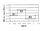
- a measurement potential E2 based on the counter electrode is applied to the working electrode.
- the adjustment potential E1 lower than the measurement potential E2 is applied to the working electrode.
- the adjustment potential E1 to the working electrode prior to the measurement of the oxidation current, impurities adhering to the working electrode and the counter electrode are removed by an electrochemical reaction, so that the counter electrode is used as a reference.
- the current component due to the electrochemical reaction of impurities attached to the working electrode and the counter electrode can be reduced, and the current component included in the response current Since the ratio of the oxidation current can be increased, it is possible to improve the measurement accuracy of the oxidation current to be measured.
- JP-T 2009-533690 paragraphs 0008-0012, abstract, etc.
- the present invention has been made in view of the above problems, and among the current components included in the response current obtained by applying a measurement potential based on the counter electrode to the working electrode, the measurement target substance and the enzyme in the specimen By reducing the effect of current components different from the oxidation current caused by the oxidation of the reducing substance produced by the reaction of, the measurement accuracy when quantifying the measurement target substance contained in the sample can be improved.
- the purpose is to provide technology that can be used.
- a method for measuring a substance of the present invention includes a reaction layer including a cavity to which a specimen is supplied, an electrode system including a working electrode and a counter electrode, and an enzyme that specifically reacts with the measurement target substance. And using the biosensor having a measurement potential based on the counter electrode as a reducing substance generated by the reaction between the measurement target substance and the reaction layer contained in the specimen supplied to the cavity.
- the measurement potential is applied to the working electrode after the sample is supplied to the cavity.
- an adjustment potential higher than the measurement potential with reference to the counter electrode is applied to the working electrode in a pulse form at least once (claim). ).
- the measurement potential is characterized by having a magnitude greater than or equal to an oxidation potential at which the reducing substance is oxidized (claim 2).
- the adjustment potential is characterized by being lower than the decomposition voltage of water (Claim 3).
- the pulse width when the adjustment potential is applied to the working electrode is 30 to 750 milliseconds (claim 4).
- the adjustment potential is applied before 1 second has elapsed since the supply of the specimen to the cavity is detected (Claim 5).
- the measurement potential is applied after 1 second or more has elapsed since the supply of the specimen to the cavity is detected (Claim 6).
- the volume of the cavity is smaller than 0.6 ⁇ l (Claim 7).
- the oxidation current due to the oxidation of the reducing substance produced by the reaction between the measurement target substance and the enzyme in the specimen is measured.
- the adjustment potential that is higher than the measurement potential with respect to the counter electrode is applied to the working electrode in a pulsed manner at least once. Impurities adhering to the working electrode and the counter electrode that react electrochemically when a potential is applied are removed from the working electrode and the counter electrode by reacting electrochemically by applying a regulated potential to the working electrode with reference to the counter electrode. Is done.
- the reducing substance produced by the reaction between the measurement target substance in the sample and the enzyme is oxidized.
- the influence of the current component different from the oxidation current can be reduced, so that the measurement accuracy when quantifying the measurement target substance contained in the specimen can be improved.
- the measurement potential is greater than or equal to the oxidation potential at which the reducing substance due to the enzymatic reaction of the measurement target substance is oxidized.
- the amount of reducing substance contained in the sample does not increase, fluctuations in the concentration of reducing substance in the sample can be suppressed, and the oxidation current due to oxidation of the reducing substance can be stabilized.
- the measurement accuracy when quantifying the target substance can be improved.
- the adjustment potential is lower than the decomposition voltage of water, when the adjustment potential is applied to the working electrode, water is electrolyzed to increase the ion concentration of the specimen. Therefore, it is possible to reduce the current component due to the ionic substance included in the response current measured when the measured potential is applied to the working electrode and the water is electrolyzed. It is possible to prevent the current measurement accuracy from deteriorating.
- the pulse width when the adjustment potential is applied to the working electrode is 30 to 750 milliseconds, the amount of the reducing substance that undergoes an oxidation reaction when the adjustment potential is applied to the working electrode. Therefore, when the measured potential is applied to the working electrode, fluctuations in the oxidation current measured by oxidation of the reducing substance can be suppressed.
- the reducing substance when the specimen is supplied to the cavity, the reducing substance is generated by the reaction between the measurement target substance in the specimen and the enzyme, but the supply of the specimen to the cavity is detected.
- the adjustment potential is applied to the working electrode before 1 second elapses, that is, before the amount of the reducing substance in the sample increases due to the progress of the oxidation-reduction reaction between the substance to be measured and the enzyme. Therefore, the amount of the reducing substance that undergoes oxidation reaction can be suppressed by applying the adjustment potential to the working electrode, and the oxidation-reduction reaction between the substance to be measured and the enzyme further proceeds after the adjustment potential is applied to the working electrode. As a result, the amount of the reducing substance in the specimen increases, so that the adjustment potential is applied, so that when the measured potential is applied to the working electrode, the reducing substance is oxidized and the measured oxidation current fluctuates. Can be suppressed.
- a reducing substance is generated by the reaction between the substance to be measured in the specimen and the enzyme, but after one second or more has passed since the supply of the specimen to the cavity was detected, that is, The measurement potential is applied to the working electrode after the amount of the reducing substance in the sample is sufficiently increased by the progress of the oxidation-reduction reaction between the substance to be measured and the enzyme. Therefore, it is possible to reliably measure the oxidation current caused by applying the measurement potential to the working electrode and oxidizing the reducing substance.
- the volume of the cavity is smaller than 0.6 ⁇ l, and the measurement target substance can be quantified with a small amount of specimen supplied to the cavity.
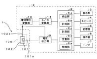
- FIG. 1 is a diagram showing an example of a biosensor system used in the method for measuring a substance of the present invention.
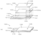
- 2A and 2B are diagrams illustrating an example of a biosensor, in which FIG. 2A is an exploded perspective view and FIG. 2B is a perspective view.
- FIG. 3 is a flowchart showing an example of the measurement process.
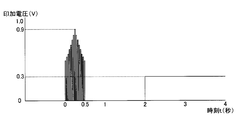
- FIG. 4 is a diagram illustrating an example of a potential applied to the working electrode with reference to the counter electrode.
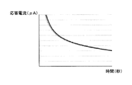
- FIG. 5 is a diagram illustrating an example of a response current obtained by applying a measurement potential to the working electrode.
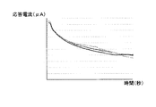
- FIG. 6 is a diagram showing a comparative example of response current obtained by applying a measurement potential to the working electrode.
- FIG. 1 is a diagram showing an example of a biosensor system used in the method for measuring a substance of the present invention.
- FIG. 3 is a flowchart showing an example of the measurement process.
- FIG. 4 is a diagram illustrating an example of a potential applied to the working electrode
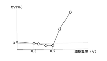
- FIG. 7 is a diagram showing the relationship between the magnitude of the adjustment potential applied to the working electrode and the coefficient of variation of the measured response current.
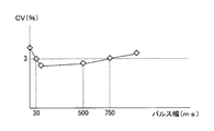
- FIG. 8 is a diagram showing the relationship between the pulse width of the adjustment potential applied to the working electrode and the variation coefficient of the measured response current.
- the biosensor system 1 includes a cavity 103 to which a specimen is supplied, an electrode system including a working electrode 101 and a counter electrode 102, and a reaction layer (illustration) including an enzyme that specifically reacts with a measurement target substance. And a measuring device 2 to which the biosensor 100 is detachably attached. Then, the biosensor system 1 includes a measurement target substance such as glucose contained in a specimen such as blood supplied to the cavity 103 provided on the distal end side of the biosensor 100 attached to the measuring device 2, and the biosensor 100.
- a measurement target substance such as glucose contained in a specimen such as blood supplied to the cavity 103 provided on the distal end side of the biosensor 100 attached to the measuring device 2, and the biosensor 100.
- the measuring instrument 2 is automatically turned on when the attachment of the biosensor 100 is detected.
- a specimen such as blood is supplied to the biosensor 100
- the measuring instrument 2 measures a measurement target substance such as glucose in the specimen.
- the measurement result is displayed on the display unit 3 formed by a display means such as an LCD, and an alarm for signaling the end of the measurement is output from the speaker 4.
- the measurement result is stored in the storage unit 5 formed by a storage medium such as a memory.
- the measuring instrument 2 includes an operation unit 6 formed by operation switches and the like, and various initial settings are executed by operating the operation unit 6 or past measurements stored in the storage unit 5 are performed. Results and the like are displayed on the display unit 3.
- the measuring instrument 2 includes a serial interface 7 (I / F), and can transmit and receive data such as measurement results to and from an external personal computer connected via the I / F 7.
- the storage unit 5 quantifies the measurement target substance contained in the sample based on the past measurement results and the response current measured by applying a predetermined measurement potential to the working electrode 101 of the biosensor 100.
- achieve various functions are stored.
- the measuring instrument 2 includes a voltage output unit 9, a current-voltage conversion unit 10, and an A / D conversion unit 11.
- the voltage output unit 9 has a digital-analog conversion function (D / A conversion function), and applies a constant reference potential to the counter electrode 102 of the biosensor 100 attached to the measuring device 2 based on a control command from the CPU 8. In addition to outputting, a predetermined potential based on the reference potential applied to the counter electrode 102 is output to the working electrode 101.
- the current-voltage conversion unit 10 has a general current-voltage conversion circuit formed by an operational amplifier or a resistance element, and operates by applying a predetermined measurement potential to the working electrode 101 of the biosensor 100 by the voltage output unit 9. The response current flowing between the pole 101 and the counter electrode 102 is converted into a voltage signal so that it can be taken into the CPU 8.
- the A / D converter 11 converts the voltage signal converted by the current-voltage converter 10 into a digital signal. Then, the digital signal converted by the A / D conversion unit 11 is taken into the CPU 8, and a predetermined calculation is performed in the CPU 8, whereby the voltage signal is converted into a current signal.
- the CPU 8 has the following functions by executing various programs stored in the storage unit 5 for quantifying the measurement target substance contained in the specimen.
- the detection unit 8a monitors the value of the current flowing between the working electrode 101 and the counter electrode 102 input to the CPU 8 via the A / D conversion unit 11, so that the specimen between the working electrode 101 and the counter electrode 102 is made of a liquid. The change of the resistance value due to the short circuit is detected by this, and thereby, it is detected that the specimen is supplied to the cavity 103 provided in the biosensor 100.
- the time measuring unit 8b Based on a clock signal output from a clock circuit (not shown), the time measuring unit 8b, for example, an elapsed time after the detection unit 8a detects the supply of the specimen to the cavity 103, and the operation by the voltage output unit 9 are used. Time for applying a predetermined potential to the pole 101 is measured.
- the measuring unit 8 c measures a response current flowing between the working electrode 101 and the counter electrode 102 when a predetermined measurement potential with the counter electrode 102 as a reference is applied to the working electrode 101 by the voltage output unit 9.
- the quantification unit 8d quantifies the measurement target substance based on the response current measured by the measurement unit 8c. Specifically, the relationship between the response current measured when a predetermined measurement voltage based on the counter electrode 102 is applied to the working electrode 101 and the concentration of the measurement target substance contained in the specimen is measured in advance. Thus, a conversion formula for converting the concentration of the measurement target substance from the response current is derived and stored in the storage unit 5 in advance. Then, the measurement target substance is quantified based on the conversion formula stored in the storage unit 5 and the actually measured response current.
- the notification unit 8e performs notification by displaying the quantification result by the quantification unit 8d on the display unit 3 or by outputting an alarm indicating that the measurement is completed from the speaker 4.
- the biosensor 100 is formed of an insulating material such as ceramic, glass, plastic, paper, biodegradable material, polyethylene terephthalate, and the like, and an electrode layer provided with a working electrode 101 and a counter electrode 102.
- 110, the cover layer 130 in which the air hole 105 is formed, and the spacer layer 120 in which the slit 104 for forming the cavity 103 is formed and is sandwiched between the electrode layer 110 and the cover layer 130 are shown in FIG.
- (a) it forms by laminating
- the electrode layer 110 is formed of a substrate made of polyethylene terephthalate.
- the spacer layer 120 is formed of a substrate made of polyethylene terephthalate, and a slit 104 for forming the cavity 103 is formed at substantially the center of the front edge portion of the substrate, as shown in FIG.
- the electrode layer 110 and the electrode layer 110 are laminated and bonded together with their tips aligned.
- the reaction layer is formed by, for example, carboxymethylcellulose or gelatin before the cover layer 130 is laminated on the working electrode 101 and the counter electrode 102 that are partially exposed in the cavity 103 formed by laminating the spacer layer 120 on the electrode layer 110. It is formed by dropping a reagent containing additives such as thickener, enzyme, mediator, amino acid and organic acid. Further, a hydrophilic agent such as a surfactant or phospholipid is applied to the inner wall of the cavity 103 in order to smoothly supply a specimen such as blood to the cavity 103.
- Enzymes include glucose oxidase, lactate oxidase, cholesterol oxidase, alcohol oxidase, sarcosine oxidase, fructosylamine oxidase, pyruvate oxidase, glucose dehydrogenase, lactate dehydrogenase, alcohol dehydrogenase, hydroxybutyrate dehydrogenase, cholesterol esterase, creatininase, creatinase DNA polymerase or the like can be used, and various sensors can be formed by selecting these enzymes according to the substance to be measured.
- glucose oxidase or glucose dehydrogenase can be used to form a glucose sensor that detects glucose in a specimen
- alcohol oxidase or alcohol dehydrogenase can be used to form an alcohol sensor that detects ethanol in a specimen
- lactate oxidase can be used to form a specimen.
- a lactic acid sensor for detecting lactic acid therein can be formed, and a total cholesterol sensor can be formed by using a mixture of cholesterol esterase and cholesterol oxidase.
- potassium ferricyanide As the mediator, potassium ferricyanide, ferrocene, ferrocene derivatives, benzoquinone, quinone derivatives, osmium complexes, ruthenium complexes and the like can be used.
- carboxymethyl cellulose carboxyethyl cellulose, polyethyleneimine DEAE cellulose dimethylaminoethyl dextran carrageenan sodium alginate dextran and the like can be used.
- a surfactant such as Triton X100, Tween 20, sodium bis (2-ethylhexyl) sulfosuccinate, or a phospholipid such as lecithin can be used.
- a buffer such as phosphoric acid may be provided in order to reduce variation in the concentration of ions contained in a specimen such as blood.
- the cover layer 130 is formed of a substrate made of polyethylene terephthalate, and an air hole 105 communicating with the cavity 103 when formed on the spacer layer 120 is formed in the substrate. Then, after the reaction layer is formed on the working electrode 101 and the counter electrode 102 exposed to the cavity 103, a cover layer 130 is laminated on the spacer layer 120 and adhered, thereby supplying a specimen such as blood to the cavity 103. Therefore, the biosensor 100 in which the specimen introduction port 103a communicating with the cavity 103 is formed at the tip is formed. In addition, the slit 104 is formed in the spacer layer 120 so that the capacity of the cavity 103 of the biosensor 103 is smaller than about 0.6 ⁇ l.
- the biosensor system 1 is formed for the purpose of quantifying glucose in blood, and includes glucose dehydrogenase as an enzyme that specifically reacts with glucose as a measurement target substance.
- a reaction layer containing potassium ferricyanide as a mediator that is reduced by electrons generated by the reaction between glucose and glucose dehydrogenase, which is a reducing substance, is provided on the working electrode 101 and the counter electrode 102 exposed to the cavity 103.
- the sample introduction port 103a at the tip when the sample is brought into contact with the sample introduction port 103a at the tip, the sample is sucked toward the air hole 105 by a capillary phenomenon and supplied to the cavity 103. Then, when the reaction layer dissolves in the specimen supplied to the cavity 103, electrons are released by the enzymatic reaction between glucose and glucose dehydrogenase, which are measurement target substances in the specimen, and ferricyanide ions are released by the emitted electrons. By being reduced, ferrocyanide ions, which are reducing substances, are generated.
- the measuring device 2 applies at least one adjustment potential higher than the measurement potential with reference to the counter electrode 102 before applying the measurement potential for measuring the oxidation current.
- impurities such as dust and dust adhering to the working electrode 101 and the counter electrode 102 are removed.
- the measuring device 2 applies a measured potential to the working electrode 101, and then has a measured potential that is greater than or equal to the oxidation potential at which the reducing substance generated by the oxidation-reduction reaction caused by the reaction layer dissolving in the specimen is oxidized.
- the counter electrode 102 By applying the counter electrode 102 to the working electrode 101 of the biosensor 100 as a reference and electrochemically oxidizing the reducing substance, the oxidation current flowing between the working electrode 101 and the counter electrode 102 is measured, thereby measuring the concentration in the specimen. Glucose is quantified.
- the biosensor 100 is formed in a bipolar electrode structure having a working electrode 101 and a counter electrode 102.
- the biosensor 100 is formed in a tripolar electrode structure by further providing a reference electrode. Also good.
- a predetermined measurement potential based on the counter electrode 102 may be applied to the working electrode 101 in a state where the counter electrode 102 is grounded and a reference potential is applied to the reference electrode by the voltage output unit 9.
- the specimen is supplied to the cavity 103 by monitoring a current flowing between the working electrode 101 and the counter electrode 102 by applying a predetermined voltage between the working electrode 101 and the counter electrode 102.
- a sample detection electrode is further provided, and a predetermined voltage is applied between the counter electrode 102 and the sample detection electrode, whereby the counter electrode 102 and the sample detection electrode are interposed.
- the cover layer 130 is formed of a transparent member so that it can be visually recognized that the specimen is supplied to the cavity 103. desirable.
- ⁇ Measurement process> an example of measurement processing executed in the biosensor system 1 will be described.
- a detection circuit not shown
- a blood sample is supplied to the cavity 103 of the biosensor 100 between the working electrode 101 and the counter electrode 102.
- a specimen detection voltage for detecting the detection is applied (step S1).
- the detection unit 8a detects that the specimen is supplied to the cavity 103 (step S2).
- the voltage output unit 9 detects that the supply of the sample to the cavity 103 is detected for 1 second, preferably 0.5 seconds.
- the adjustment potential is applied to the working electrode 101 with the counter electrode 102 as a reference (step S3).
- the voltage output unit 9 causes the working electrode 101 to be measured with the counter electrode 102 as a reference. Is applied (step S4).
- a response current (oxidation current) about 3 to 5 seconds after the supply of the specimen to the cavity 103 is detected is measured by the measuring unit 8c (Step S1). S5). Then, the glucose contained in the sample is quantified based on the measured current value of the response current and the conversion formula stored in the storage unit 5, and the measurement result is notified by the notification unit 8e. Is finished (step S6).
- the measurement potential is set to a magnitude equal to or higher than the oxidation potential at which ferrocyanide ions, which are reducing substances generated as a result of the enzymatic reaction of glucose, are oxidized, and set to about 0.3V. ing.
- the adjustment potential is set to about 0.9 V, which is higher than the measurement potential and lower than the water decomposition voltage (about 1 V).
- FIG. 5 shows a measurement result when the response current is measured three times under the same conditions as those in the “measurement process” described above.
- FIG. 6 shows a measurement result when the response current is measured three times under the same conditions as those in the “measurement process” except that the adjustment potential is not applied to the working electrode 101.
- the reducing substance generated by the reaction between the measurement target substance and the enzyme in the specimen is oxidized.
- an adjustment potential higher than the measurement potential with respect to the counter electrode 102 is applied to the working electrode 101 at least once as a pulse. Therefore, the impurities adhering to the working electrode 101 and the counter electrode 102 that electrochemically react when the measurement potential is applied to the working electrode 101 are applied to the working electrode 101 with reference to the counter electrode 102. It is electrochemically reacted and removed from the working electrode 101 and the counter electrode 102.
- the reducing substance generated by the reaction between the measurement target substance in the sample and the enzyme As a result, it is possible to reduce the influence of current components that are different from the oxidation current due to the oxidation of oxygen, so that the response current can be measured stably and the measurement accuracy when quantifying the measurement target substance contained in the sample is improved. can do.
- the measurement potential is greater than or equal to the oxidation potential at which the reducing substance due to the enzyme reaction of the measurement target substance is oxidized
- the reducing substance contained in the specimen by the reduction reaction by applying the measurement potential to the working electrode 101 When quantifying the measurement target substance, the fluctuation of the concentration of the reducing substance in the sample can be suppressed and the oxidation current due to oxidation of the reducing substance can be stabilized. The measurement accuracy can be improved.
- the adjustment potential is lower than the decomposition voltage of water, it is possible to prevent the ion concentration of the specimen from increasing due to the electrolysis of water when the adjustment potential is applied to the working electrode 101. Therefore, the response current is measured when the measurement potential is applied to the working electrode 101, and the current component due to the ionic substance due to the electrolysis of water contained in the response current can be reduced, and the oxidation current can be reduced. It is possible to prevent the measurement accuracy from deteriorating.
- the pulse width when the adjustment potential is applied to the working electrode 101 is 0.2 seconds, the amount of the reducing substance that undergoes an oxidation reaction when the adjustment potential is applied to the working electrode 101 can be suppressed. Therefore, it is possible to suppress fluctuations in the oxidation current measured when the reducing substance is oxidized when the measurement potential is applied to the working electrode 101.
- the pulse width of the adjustment potential applied to the working electrode 101 in a pulse shape is not limited to 0.2 seconds. Measures the relationship between the pulse width of the adjustment potential applied to the working electrode 101 and the coefficient of variation (CV: Coefficient of variation) of the response current (oxidation current) measured when the measurement potential is applied to the working electrode 101. As a result, the following results were obtained. That is, as shown in FIG. 8, when the pulse width of the adjustment potential is about 30 milliseconds to about 750 milliseconds, the CV of the response current measured when the measurement potential is applied to the working electrode 101 is 3 % Or less.
- the adjustment potential is applied to the working electrode 101 before, that is, before the amount of the reducing substance in the specimen increases due to the progress of the oxidation-reduction reaction between the measurement target substance and the enzyme. Therefore, the amount of the reducing substance that undergoes an oxidation reaction can be suppressed by applying the adjustment potential to the working electrode 101, and after the adjustment potential is applied to the working electrode 101, the oxidation-reduction reaction between the substance to be measured and the enzyme occurs. Since the amount of the reducing substance in the specimen increases as the process proceeds further, the adjustment potential is applied, so that when the measurement potential is applied to the working electrode 101, the reducing substance is oxidized and the measured oxidation current varies. Can be suppressed.
- a reducing substance is generated by the reaction between the measurement target substance in the sample and the enzyme, but after one second or more has elapsed since the supply of the sample to the cavity 103 was detected, that is, the measurement target substance and the enzyme
- the measurement potential is applied to the working electrode 101 after the amount of the reducing substance in the specimen has sufficiently increased due to the progress of the oxidation-reduction reaction. Therefore, it is possible to reliably and stably measure an oxidation current caused by applying a measurement potential to the working electrode 101 and oxidizing the reducing substance.
- the reaction of the above-described biosensor 100 is possible. You may form an ethanol sensor, a lactic acid sensor, etc. by changing the combination of the enzyme and mediator which are contained in a layer.
- the reaction layer does not necessarily include a mediator.
- the oxidation current due to oxidation of reducing substances such as hydrogen peroxide and enzyme reducts generated by the enzymatic reaction of the measurement target substance such as glucose is measured. do it.
- the measurement potential may be applied to the working electrode 101 before 1 second or more has elapsed since the supply of the specimen to the cavity 103 is detected.
- the measurement potential of about 0.3 V may be applied to the working electrode 101 immediately after the adjustment potential of about 0.9 V is applied to the working electrode 101 with the counter electrode 102 as a reference with a pulse width of about 0.2 seconds.
- the adjustment potential may be applied to the working electrode 101 a plurality of times in a pulsed manner after the supply of the sample to the cavity 103 is detected.
- the voltage output unit 9 applies a 0.9 V pulsed adjustment potential to the working electrode 101 a plurality of times with reference to the counter electrode 102 before 1 second, preferably 0.5 seconds, after the supply is detected. May be.
- the adjustment potential does not have to be a constant potential.
- the voltage output unit 9 may apply a pulsed adjustment potential having different potentials with the counter electrode 102 as a reference to the working electrode 101 a plurality of times.
- 9 to 11 are diagrams showing other examples of potentials applied to the working electrode with reference to the counter electrode.
- the adjustment potential is not necessarily applied to the working electrode 101 immediately after the supply of the sample to the cavity 103 is detected.
- the adjustment potential is 1 after the supply of the sample to the cavity 103 is detected. It may be applied to the working electrode 101 over a second.
- pulse-shaped adjustment potentials having different pulse widths and potentials may be applied to the working electrode 101 a plurality of times.
- an adjustment potential equal to or higher than the water decomposition voltage may be applied to the working electrode 101.
- the voltage between the working electrode 101 and the counter electrode 102 is set to 0 V after the adjustment potential based on the counter electrode 102 is applied to the working electrode 101.
- the circuit may be opened after the adjustment potential is applied to the working electrode 101.
- the capacity of the cavity 103 of the biosensor 100 be made smaller.
- the present invention can be applied to a method for measuring substances using various biosensors.
Landscapes
- Chemical & Material Sciences (AREA)
- Life Sciences & Earth Sciences (AREA)
- Health & Medical Sciences (AREA)
- Organic Chemistry (AREA)
- Proteomics, Peptides & Aminoacids (AREA)
- Zoology (AREA)
- Wood Science & Technology (AREA)
- Engineering & Computer Science (AREA)
- Physics & Mathematics (AREA)
- Analytical Chemistry (AREA)
- General Health & Medical Sciences (AREA)
- Biochemistry (AREA)
- Immunology (AREA)
- Molecular Biology (AREA)
- Genetics & Genomics (AREA)
- Biophysics (AREA)
- General Engineering & Computer Science (AREA)
- Biotechnology (AREA)
- Microbiology (AREA)
- Bioinformatics & Cheminformatics (AREA)
- Hematology (AREA)
- Pathology (AREA)
- Chemical Kinetics & Catalysis (AREA)
- Electrochemistry (AREA)
- General Physics & Mathematics (AREA)
- Emergency Medicine (AREA)
- Apparatus Associated With Microorganisms And Enzymes (AREA)
- Investigating Or Analysing Biological Materials (AREA)
- Measuring Or Testing Involving Enzymes Or Micro-Organisms (AREA)
Abstract
La présente invention porte sur une technique qui permet à une précision de mesure d'être améliorée lors de la quantification d'une substance à mesurer, qui est contenue dans un échantillon, en diminuant l'impact de composantes de courant différent du courant d'oxydation résultant de l'oxydation d'une substance réductrice produite par une réaction entre des enzymes et la substance à mesurer dans l'échantillon, parmi les composantes de courant dans un courant de réponse obtenu par application d'un potentiel de mesure basé sur contre-électrode à une électrode de travail. Du fait qu'un potentiel de réglage ayant un potentiel supérieur à un potentiel de mesure est appliqué sous la forme d'une impulsion à l'électrode de travail, parmi les composantes de courant contenues dans le courant de réponse obtenu par application du potentiel de mesure basé sur contre-électrode à l'électrode de travail, l'impact des composantes de courant différent du courant d'oxydation résultant de l'oxydation de la substance réductrice produite par la réaction entre la substance à mesurer et des enzymes dans l'échantillon peut être réduit. Ainsi, le courant de réponse peut être mesuré de façon stable et une précision de mesure peut être améliorée lors de la quantification de la substance à mesurer, qui est contenue de l'échantillon.
Priority Applications (4)
| Application Number | Priority Date | Filing Date | Title |
|---|---|---|---|
| EP12849902.7A EP2781915A1 (fr) | 2011-11-18 | 2012-07-10 | Procédé de mesure de substances |
| IN3415CHN2014 IN2014CN03415A (fr) | 2011-11-18 | 2012-07-10 | |
| CN201280055939.7A CN103946701A (zh) | 2011-11-18 | 2012-07-10 | 物质的测定方法 |
| US14/278,539 US20140246336A1 (en) | 2011-11-18 | 2014-05-15 | Substance determination method |
Applications Claiming Priority (2)
| Application Number | Priority Date | Filing Date | Title |
|---|---|---|---|
| JP2011-252765 | 2011-11-18 | ||
| JP2011252765 | 2011-11-18 |
Related Child Applications (1)
| Application Number | Title | Priority Date | Filing Date |
|---|---|---|---|
| US14/278,539 Continuation US20140246336A1 (en) | 2011-11-18 | 2014-05-15 | Substance determination method |
Publications (1)
| Publication Number | Publication Date |
|---|---|
| WO2013073074A1 true WO2013073074A1 (fr) | 2013-05-23 |
Family
ID=48429179
Family Applications (1)
| Application Number | Title | Priority Date | Filing Date |
|---|---|---|---|
| PCT/JP2012/004442 WO2013073074A1 (fr) | 2011-11-18 | 2012-07-10 | Procédé de mesure de substances |
Country Status (6)
| Country | Link |
|---|---|
| US (1) | US20140246336A1 (fr) |
| EP (1) | EP2781915A1 (fr) |
| JP (1) | JPWO2013073074A1 (fr) |
| CN (1) | CN103946701A (fr) |
| IN (1) | IN2014CN03415A (fr) |
| WO (1) | WO2013073074A1 (fr) |
Cited By (3)
| Publication number | Priority date | Publication date | Assignee | Title |
|---|---|---|---|---|
| JP2016061772A (ja) * | 2014-09-17 | 2016-04-25 | アイセンス,インコーポレーテッド | 生体試料内の分析対象物質の濃度測定方法および測定装置 |
| WO2023145300A1 (fr) * | 2022-01-27 | 2023-08-03 | Phcホールディングス株式会社 | Dispositif de mesure d'échantillon, procédé de mesure d'échantillon et programme de mesure d'échantillon |
| WO2024101215A1 (fr) * | 2022-11-11 | 2024-05-16 | 東洋紡株式会社 | Procédé de mesure de matrice dans un échantillon |
Families Citing this family (3)
| Publication number | Priority date | Publication date | Assignee | Title |
|---|---|---|---|---|
| JP6116080B1 (ja) * | 2016-04-26 | 2017-04-19 | 日本航空電子工業株式会社 | 電気化学測定方法、電気化学測定装置及びトランスデューサ |
| EP4266036A4 (fr) * | 2020-12-21 | 2024-09-11 | Fujidenolo Co Ltd | Dispositif de mesure et procédé de mesure |
| CN113358726A (zh) * | 2021-05-18 | 2021-09-07 | 北京大学第一医院 | 用于电化学方法检测肌酐的电极、试纸及其制备方法 |
Citations (6)
| Publication number | Priority date | Publication date | Assignee | Title |
|---|---|---|---|---|
| JP2000162176A (ja) * | 1998-09-22 | 2000-06-16 | Omron Corp | バイオセンサを用いた測定方法及び測定装置 |
| JP2007033459A (ja) * | 2006-10-03 | 2007-02-08 | Matsushita Electric Ind Co Ltd | バイオセンサ、バイオセンサ用測定装置及び基質の定量方法 |
| JP2009533690A (ja) * | 2006-04-12 | 2009-09-17 | ダイオネックス コーポレイション | パルス式電気化学検出方法 |
| WO2009119118A1 (fr) * | 2008-03-27 | 2009-10-01 | パナソニック株式会社 | Dispositif de mesure d'échantillon, système de mesure d'échantillon et procédé de mesure d'échantillon |
| JP2010504524A (ja) * | 2006-09-22 | 2010-02-12 | バイエル・ヘルスケア・エルエルシー | 改善された安定性およびヘマトクリット性能(performance)を有するバイオセンサー系 |
| JP2011158483A (ja) * | 2004-04-19 | 2011-08-18 | Panasonic Corp | 血液成分の測定方法、それに用いるバイオセンサおよび測定装置 |
Family Cites Families (2)
| Publication number | Priority date | Publication date | Assignee | Title |
|---|---|---|---|---|
| US8778168B2 (en) * | 2007-09-28 | 2014-07-15 | Lifescan, Inc. | Systems and methods of discriminating control solution from a physiological sample |
| WO2011024487A1 (fr) * | 2009-08-31 | 2011-03-03 | パナソニック株式会社 | Capteur et procédé de mesure d'une concentration |
-
2012
- 2012-07-10 EP EP12849902.7A patent/EP2781915A1/fr not_active Withdrawn
- 2012-07-10 CN CN201280055939.7A patent/CN103946701A/zh active Pending
- 2012-07-10 JP JP2013544086A patent/JPWO2013073074A1/ja not_active Withdrawn
- 2012-07-10 WO PCT/JP2012/004442 patent/WO2013073074A1/fr active Application Filing
- 2012-07-10 IN IN3415CHN2014 patent/IN2014CN03415A/en unknown
-
2014
- 2014-05-15 US US14/278,539 patent/US20140246336A1/en not_active Abandoned
Patent Citations (6)
| Publication number | Priority date | Publication date | Assignee | Title |
|---|---|---|---|---|
| JP2000162176A (ja) * | 1998-09-22 | 2000-06-16 | Omron Corp | バイオセンサを用いた測定方法及び測定装置 |
| JP2011158483A (ja) * | 2004-04-19 | 2011-08-18 | Panasonic Corp | 血液成分の測定方法、それに用いるバイオセンサおよび測定装置 |
| JP2009533690A (ja) * | 2006-04-12 | 2009-09-17 | ダイオネックス コーポレイション | パルス式電気化学検出方法 |
| JP2010504524A (ja) * | 2006-09-22 | 2010-02-12 | バイエル・ヘルスケア・エルエルシー | 改善された安定性およびヘマトクリット性能(performance)を有するバイオセンサー系 |
| JP2007033459A (ja) * | 2006-10-03 | 2007-02-08 | Matsushita Electric Ind Co Ltd | バイオセンサ、バイオセンサ用測定装置及び基質の定量方法 |
| WO2009119118A1 (fr) * | 2008-03-27 | 2009-10-01 | パナソニック株式会社 | Dispositif de mesure d'échantillon, système de mesure d'échantillon et procédé de mesure d'échantillon |
Non-Patent Citations (1)
| Title |
|---|
| SHIGERU YAMAUCHI ET AL.: "Hakkinkoku o Mochiita Micro Bio Sensor", KAGAKU KOGYO, vol. 44, no. 10, 1 October 1993 (1993-10-01), pages 796 - 800, XP008174078 * |
Cited By (3)
| Publication number | Priority date | Publication date | Assignee | Title |
|---|---|---|---|---|
| JP2016061772A (ja) * | 2014-09-17 | 2016-04-25 | アイセンス,インコーポレーテッド | 生体試料内の分析対象物質の濃度測定方法および測定装置 |
| WO2023145300A1 (fr) * | 2022-01-27 | 2023-08-03 | Phcホールディングス株式会社 | Dispositif de mesure d'échantillon, procédé de mesure d'échantillon et programme de mesure d'échantillon |
| WO2024101215A1 (fr) * | 2022-11-11 | 2024-05-16 | 東洋紡株式会社 | Procédé de mesure de matrice dans un échantillon |
Also Published As
| Publication number | Publication date |
|---|---|
| US20140246336A1 (en) | 2014-09-04 |
| CN103946701A (zh) | 2014-07-23 |
| JPWO2013073074A1 (ja) | 2015-04-02 |
| EP2781915A1 (fr) | 2014-09-24 |
| IN2014CN03415A (fr) | 2015-10-09 |
Similar Documents
| Publication | Publication Date | Title |
|---|---|---|
| WO2013073074A1 (fr) | Procédé de mesure de substances | |
| EP3343213B1 (fr) | Capteur | |
| JP2018165729A (ja) | 電気化学式バイオセンサを用いた物質の測定方法及び測定装置 | |
| JP5708878B2 (ja) | バイオセンサおよびその製造方法 | |
| JP2005003679A (ja) | 電気化学バイオセンサ | |
| CN105452855A (zh) | 带有相对裸电极的可溶电化学活性涂层的基于电化学的分析测试条 | |
| WO2013073072A1 (fr) | Procédé de mesure de niveaux d'hématocrite, procédé d'analyse quantitative utilisant ledit procédé de mesure et puce de capteur | |
| CN104024857B (zh) | 个人血糖仪和用于感测使用个人血糖仪的异常测量的方法 | |
| JP5001240B2 (ja) | バイオセンサ、その製造方法、その使用方法 | |
| JP5655977B2 (ja) | バイオセンサ | |
| JP6607437B2 (ja) | バイオセンサ | |
| JP5509969B2 (ja) | 測定装置及び測定方法 | |
| WO2011151953A1 (fr) | Procédé de mesure de substance | |
| JP2000180399A (ja) | 基質の定量方法 | |
| WO2013073073A1 (fr) | Biocapteur et procédé de production de biocapteur | |
| JP2014089096A (ja) | バイオセンサ | |
| JP2014089097A (ja) | バイオセンサ | |
| US10613050B2 (en) | Bio sensor and sensing method thereof | |
| JP5429426B2 (ja) | バイオセンサシステム | |
| JP6610025B2 (ja) | バイオセンサ | |
| JP2012122744A (ja) | バイオセンサの製造方法およびこの方法により製造されたバイオセンサ | |
| Takagi et al. | BIOSENSOR | |
| JPWO2014064978A1 (ja) | バイオセンサおよびその製造方法 | |
| JP2013108791A (ja) | バイオセンサの製造方法およびバイオセンサ | |
| JPH08338824A (ja) | バイオセンサ、バイオセンサの製造方法および特定化合物の定量法 |
Legal Events
| Date | Code | Title | Description |
|---|---|---|---|
| 121 | Ep: the epo has been informed by wipo that ep was designated in this application |
Ref document number: 12849902 Country of ref document: EP Kind code of ref document: A1 |
|
| WWE | Wipo information: entry into national phase |
Ref document number: 2012849902 Country of ref document: EP |
|
| ENP | Entry into the national phase |
Ref document number: 2013544086 Country of ref document: JP Kind code of ref document: A |
|
| NENP | Non-entry into the national phase |
Ref country code: DE |