WO2013072980A1 - 撮像装置、制御装置、制御方法、及びプログラム - Google Patents
撮像装置、制御装置、制御方法、及びプログラム Download PDFInfo
- Publication number
- WO2013072980A1 WO2013072980A1 PCT/JP2011/076148 JP2011076148W WO2013072980A1 WO 2013072980 A1 WO2013072980 A1 WO 2013072980A1 JP 2011076148 W JP2011076148 W JP 2011076148W WO 2013072980 A1 WO2013072980 A1 WO 2013072980A1
- Authority
- WO
- WIPO (PCT)
- Prior art keywords
- command
- imaging
- instruction
- coordinate system
- control
- Prior art date
- Legal status (The legal status is an assumption and is not a legal conclusion. Google has not performed a legal analysis and makes no representation as to the accuracy of the status listed.)
- Ceased
Links
Images















Classifications
-
- H—ELECTRICITY
- H04—ELECTRIC COMMUNICATION TECHNIQUE
- H04N—PICTORIAL COMMUNICATION, e.g. TELEVISION
- H04N23/00—Cameras or camera modules comprising electronic image sensors; Control thereof
- H04N23/60—Control of cameras or camera modules
- H04N23/66—Remote control of cameras or camera parts, e.g. by remote control devices
- H04N23/661—Transmitting camera control signals through networks, e.g. control via the Internet
-
- H—ELECTRICITY
- H04—ELECTRIC COMMUNICATION TECHNIQUE
- H04N—PICTORIAL COMMUNICATION, e.g. TELEVISION
- H04N23/00—Cameras or camera modules comprising electronic image sensors; Control thereof
- H04N23/60—Control of cameras or camera modules
- H04N23/695—Control of camera direction for changing a field of view, e.g. pan, tilt or based on tracking of objects
Definitions
- the present invention relates to an imaging apparatus capable of delivering a captured image to a terminal via a network, and more particularly, to an exclusive process of a plurality of interfaces provided to the terminal by the imaging apparatus.
- an imaging device that changes the direction of imaging by operating a pan head.
- An imaging device that changes the direction in which the imaging device captures an image in accordance with an instruction transmitted from a control device connected to the imaging device via a network is known.
- the direction in which the imaging apparatus captures an image differs according to the same command before and after the change.
- the installation state is changed from a state where the imaging device is installed upright to a state where the imaging device is inverted and installed on the ceiling or the like.
- the imaging device operates to direct the imaging direction downward. To do.
- the installation state of the imaging device is changed from upright to inverted, the up and down and the left and right of the imaging direction of the imaging device are reversed with respect to the same command.
- an imaging system that holds a plurality of control programs for changing the imaging direction of the imaging apparatus and switches the control program to be used according to the direction in which the imaging apparatus is installed (for example, Patent Document 1). .
- This imaging system switches a coordinate system for representing an imaging direction in coordinates by switching control programs.
- the imaging apparatus can direct the imaging direction in a certain direction with respect to a specific command regardless of the installation state.
- the control device When the control device receives and displays a captured image captured by the imaging device, a change in the installation state of the imaging device also affects the orientation of the captured image displayed on the control device. Therefore, it is desirable that the orientation of the captured image can be changed. For example, when the installation state of the imaging device is changed from the upright state to the inverted state, the top, bottom, left, and right of the captured image displayed on the control device are reversed. Therefore, by rotating the captured image captured in the inverted state by 180 degrees and displaying the image on the control device, it is possible to display a captured image in which the captured image captured in the upright state coincides vertically and horizontally.
- the interface for changing the orientation of the captured image displayed on the control device and the interface for changing the coordinate system for controlling the imaging direction described above may be defined as separate commands.
- the vertical and horizontal orientations in the captured image to be displayed There are cases where the left and right orientations do not match.
- the direction and the direction of the coordinate system do not match.
- the imaging apparatus has, for example, the following configuration. That is, the imaging means, the holding means for holding the coordinate system used to represent the imaging direction of the imaging means, the first command for rotating the captured image taken by the imaging means by a predetermined angle, and the holding means Receiving means for receiving the second command for rotating the held coordinate system around the origin by the predetermined angle, and specifying information for specifying the imaging direction in the coordinate system; and specifying by the specifying information Change control means for performing control to change the image pickup direction of the image pickup means to the image pickup direction, and the receiving means after receiving one command of the first command or the second command. Control means for holding the execution of the first instruction or the second instruction received by the receiving means until the instruction is received.
- the imaging apparatus has the following configuration, for example. That is, an imaging unit, a holding unit that holds a coordinate system used to represent an area in the imaging range of the imaging unit, and a first command that rotates a captured image cut out from the area on the imaging range by a predetermined angle A second command for rotating the coordinate system held by the holding means around the origin by the predetermined angle, and specifying information for specifying in the coordinate system a region to cut out the captured image from the imaging range; Receiving means, cutting out means for cutting out the captured image of the region in the coordinate system specified by the specifying information, and the receiving means is one of the first instruction and the second instruction. Control means for holding the execution of the first instruction or the second instruction received by the receiving means from when the second instruction is received until the other instruction is received. That.
- control apparatus has the following structures, for example. That is, a control device that controls an imaging apparatus having a holding unit that holds a coordinate system used to represent the imaging direction of the imaging unit, the specifying unit for specifying the imaging direction in the coordinate system, and the specifying unit A first command for rotating a captured image captured by the imaging unit by a predetermined angle in a specified imaging direction, and a second command for rotating the coordinate system held by the holding unit about the origin by the predetermined angle Transmission control means for performing control to transmit the image to the imaging apparatus, and after the transmission control means receives an instruction to transmit one of the first instruction and the second instruction to the imaging apparatus The transmission control means suspends transmission of the command received the instruction to transmit to the imaging device until an instruction to transmit the other command to the imaging device is received.
- control apparatus has the following structures, for example. That is, a control device that controls an imaging apparatus having a holding unit that holds a coordinate system used to represent an area in the imaging range of the imaging unit, the specifying unit for specifying the area in the coordinate system, and the specifying A first command for rotating a captured image of an area on the imaging range corresponding to an area in the coordinate system specified by the means by a predetermined angle and the coordinate system held by the holding means about the origin as the center.
- a transmission control unit that performs control to transmit a second command to rotate the angle to the imaging device; and the transmission control unit sends one command of the first command or the second command to the imaging device. From receiving the instruction to transmit, until the instruction to transmit the other command to the imaging apparatus is received, the transmission control means maintains transmission of the command that has received the instruction to transmit to the imaging apparatus. Characterized in that it.
- the imaging device receives the command for changing the orientation of the captured image displayed on the control device and the command for changing the orientation of the coordinate system used for controlling the imaging direction of the imaging device independently. Even in this case, the imaging direction can be changed to the direction intended by the user.
- control device independently transmits a command for changing the orientation of the captured image to be displayed on the control device and a command for changing the orientation of the coordinate system used to control the imaging direction of the imaging device. Even in this case, the imaging direction can be changed to the direction intended by the user.
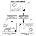
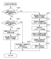
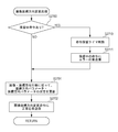
- FIG. 3 is a flowchart for explaining the operation of the imaging apparatus according to the first embodiment.
- FIG. 3 is a flowchart for explaining details of an operation of the imaging apparatus according to the first embodiment.
- FIG. 3 is a flowchart for explaining details of an operation of the imaging apparatus according to the first embodiment.
- FIG. 3 is a flowchart for explaining details of an operation of the imaging apparatus according to the first embodiment.
- FIG. 3 is a flowchart for explaining details of an operation of the imaging apparatus according to the first embodiment.
- FIG. 3 is a flowchart for explaining details of an operation of the imaging apparatus according to the first embodiment.
- FIG. 3 is a flowchart for explaining details of an operation of the imaging apparatus according to the first embodiment.
- FIG. 3 is a flowchart for explaining details of an operation of the imaging apparatus according to the first embodiment.
- the figure for demonstrating the command which the imaging device which concerns on this invention receives.
- the figure for demonstrating the command which the imaging device which concerns on this invention receives.
- the figure for demonstrating the command which the imaging device which concerns on this invention receives.
- FIG. 9 is a flowchart for explaining the operation of the imaging apparatus according to the second embodiment.
- FIG. 9 is a flowchart for explaining details of an operation of the imaging apparatus according to the second embodiment.
- FIG. 9 is a flowchart for explaining details of an operation of the imaging apparatus according to the second embodiment.
- FIG. 9 is a flowchart for explaining details of an operation of the imaging apparatus according to the second embodiment.
- FIG. 9 is a flowchart for explaining details of an operation of the imaging apparatus according to the second embodiment.
- FIG. 9 is a flowchart for explaining the operation of the control device according to the third embodiment.
- FIG. 9 is a flowchart for explaining the operation of the control device according to the third embodiment.
- Example 1 The configuration of the imaging system according to the present embodiment is shown in FIG. 1A.
- the imaging apparatus 1000 is connected to the client 3000 via the network 3020.
- the imaging apparatus 1000 distributes the captured image to the client 3000 via the network 3020.
- the network 3020 includes a plurality of routers, switches, cables, and the like that satisfy a communication standard such as Ethernet (registered trademark), for example.
- a communication standard such as Ethernet (registered trademark)
- any communication standard, scale, and configuration may be used as long as communication between the imaging apparatus 1000 and the client 3000 can be performed.
- the network 3020 may be configured by the Internet, a wired LAN (Local Area Network), a wireless LAN (Wireless LAN), a WAN (Wide Area Network), or the like.
- the client 3000 transmits a command to the imaging apparatus 1000.
- the client 3000 transmits a command for changing the imaging direction or angle of view of the imaging apparatus 1000.
- the client 3000 transmits a command to rotate the coordinate system used to represent the position in the imaging range of the imaging apparatus 1000 around the origin.
- the client 3000 includes a display unit 3010 for displaying a captured image captured by the imaging device 1000, and transmits a command for rotating the captured image displayed on the display unit 3010 in the imaging device 1000.
- the imaging apparatus 1000 changes the imaging direction in response to a command for changing the imaging direction received from the client 3000.
- the imaging apparatus 1000 changes the angle of view in accordance with a command for changing the angle of view received from the client 3000.
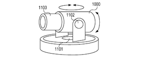
- a drive mechanism for the imaging apparatus 1000 according to the present embodiment to change the imaging direction or the angle of view will be described with reference to FIG. 1B.
- the pan driving mechanism 1101 changes the imaging direction of the imaging apparatus 1000 to the pan direction.
- the tilt drive mechanism 1102 changes the imaging direction of the imaging apparatus 1000 to the tilt direction.
- the zoom mechanism 1103 changes the angle of view of the imaging apparatus 1000.
- FIG. 2A shows an internal configuration of the imaging apparatus 1000 according to the present embodiment.
- the control unit 1001 performs overall control of the imaging apparatus 1000.
- the control unit 1001 is configured by a CPU (Central Processing Unit), for example, and executes a program stored in a memory 1002 described later.
- CPU Central Processing Unit
- the memory 1002 is used as a data storage area such as a program storage area executed by the control unit 1001, a work area during program execution, and a storage area of a captured image generated by the imaging unit 1003 described later.
- the memory 1002 holds a coordinate system used to represent the position in the imaging range of the imaging apparatus 1000.
- the memory 1002 holds an instruction hold queue for holding execution of instructions received by the communication unit 1004 described later.
- the imaging unit 1003 converts an analog signal acquired by photographing a subject into digital data.
- the imaging unit 1003 generates a captured image of the captured image by performing data compression processing using ADCT (Adaptive Discrete Cosine Transform, Adaptive Discrete Cosine Transform) or the like, and outputs the captured image to the memory 1002.
- ADCT Adaptive Discrete Cosine Transform, Adaptive Discrete Cosine Transform
- the imaging unit 1003 outputs the captured image to the memory 1002, and then transmits an image acquisition event to the control unit 1001.
- the communication unit 1004 receives from the client 3000 the imaging range change command shown in FIG. 5A, the image direction change command shown in FIG. 5B, and the coordinate direction change command shown in FIG. Upon receiving the commands shown in FIGS. 5A to 5C, the communication unit 1004 transmits a reception event to the control unit 1001. The communication unit 1004 transmits a response to the commands in FIGS. 5A to 5C to the client. In this embodiment, the communication unit 1004 sends a normal response that is a response for indicating that the received command is normally executed or an error response that is a response for indicating that the received command is not executed. Send to. An example of a normal response is shown in FIG. 5E. An example of an error response is shown in FIG. 5F.
- Time measuring unit 1005 measures the time elapsed since the imaging apparatus 1000 received the image direction change command or the coordinate direction change command.
- the time measuring unit 1005 transmits a time-out event to the control unit 1001 when a predetermined time has elapsed after receiving the image direction change command or the coordinate direction change command from the client 3000.
- the imaging control unit 1006 controls the pan driving mechanism 1101, the tilt driving mechanism 1102, and the zoom mechanism 1103 in accordance with instructions from the control unit 1001. That is, when the communication unit 1004 receives an imaging range change command, which will be described later with reference to FIG. 5A, from the client 3000, a reception event corresponding to the command is transmitted to the control unit 1001. When receiving the reception event, the control unit 1001 issues a control instruction to the imaging control unit 1006 according to the content of the reception event. Upon receiving the control instruction, the imaging control unit 1006 performs control to drive the pan driving mechanism 1101, the tilt driving mechanism 1102, or the zoom mechanism 1103 in accordance with the control instruction.
- the imaging control unit 1006 captures an image at which the imaging unit 1003 captures an image at a position specified by coordinates specified by an imaging range change command to be described later with reference to FIG. 5A and the above-described coordinate system held in the memory 1002. Change control to change direction.
- FIG. 2A is an example of a preferred embodiment of the imaging apparatus according to the present invention and is not limited thereto.
- Various modifications and changes are possible within the scope of the gist of the present invention, such as including a voice input unit.
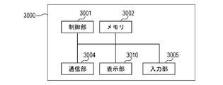
- the client 3000 is configured as a computer device connected to the network 3020.
- a control unit 3001 performs overall control of the client 3000.
- the control unit 3001 is configured by, for example, a CPU (Central Processing Unit), and executes a program stored in a memory 3002 described later.
- CPU Central Processing Unit
- the memory 3002 is used as a program storage area executed by the control unit 3001, a work area during program execution, and a data storage area.
- the communication unit 3004 receives the captured image transmitted from the imaging apparatus 1000. In addition, the communication unit 3004 transmits a command for controlling the imaging apparatus 1000.
- the input unit 3005 accepts input of instructions from the user.
- the input unit 3005 can accept input of various command transmission instructions to the imaging apparatus 1000 as instructions from the user. Details of commands to the imaging apparatus 1000 will be described later with reference to FIGS. 5A to 5C.
- the input unit 3005 notifies the control unit 3001 that a command has been input.
- the control unit 3001 generates a command for the imaging apparatus 1000 in accordance with an instruction input to the input unit 3005, and performs transmission control for transmitting the generated command to the imaging apparatus 1000 via the communication unit 3004.
- the input unit 3005 can accept an input of a user response to an inquiry message or the like to the user generated when the control unit 3001 executes a program stored in the memory 3002.
- Display unit 3010 displays the captured image received by communication unit 3004.
- the display unit 3010 can display an inquiry message to the user generated by the control unit 3001 executing a program stored in the memory 3002.
- each instruction includes a destination address indicating a destination on which the instruction is executed and information on a transmission source address indicating a transmission source of the instruction. Furthermore, each instruction has information about the contents and arguments of the instruction.
- the client 3000 changes the imaging range of the imaging apparatus 1000 by the imaging range change command.
- the arguments of the imaging range change command are pan coordinates, tilt coordinates, and zoom coordinates.
- the client 3000 and the imaging apparatus 1000 normalize the horizontal angle that can be captured by the imaging apparatus 1000 from ⁇ 1.0 to +1.0.
- the pan direction of the image pickup apparatus is represented by setting the values from ⁇ 1.0 to +1.0 as pan coordinates.
- the client 3000 and the imaging apparatus 1000 normalize the vertical angle that can be captured by the imaging apparatus 1000 from ⁇ 1.0 to +1.0.
- the tilt direction of the image pickup apparatus is expressed by using values from ⁇ 1.0 to +1.0 as tilt coordinates.
- the client 3000 and the imaging apparatus 1000 normalize the value for the range from the tele end to the wide end of the zoom from 0.0 to +1.0.
- the zoom value for example, a zoom magnification value or a focal length value can be used.
- the zoom position of the image pickup apparatus is represented using a value from 0.0 to +1.0 as zoom coordinates.
- the client 3000 can specify absolute positions of pan coordinates, tilt coordinates, and zoom coordinates, and can arbitrarily change the imaging range of the imaging apparatus 1000.
- the pan coordinate, tilt coordinate, or zoom coordinate held by the imaging range change command is identification information for identifying the imaging direction in the coordinate system held in the memory 1002.
- pan coordinates, tilt coordinates, and zoom coordinates is not limited to using normalized values as described above.
- the pan coordinate and the tilt coordinate may be specified by a moving angle from a reference position (for example, pan end, tilt end, etc.) in the movable range of the pan driving mechanism 1101 or the tilt driving mechanism 1102.
- zoom coordinates may be designated by values of zoom magnification and focal length.
- the client 3000 rotates the direction of the captured image distributed by the imaging apparatus 1000 by a predetermined angle (180 degrees in this embodiment). For example, the imaging apparatus 1000 can rotate the direction of the captured image with the intersection of diagonal lines of the captured image as the rotation center.
- the argument of the image direction change command is the image direction.
- OFF indicates the positive direction
- ON indicates the reverse direction. The positive direction and the reverse direction of the captured image will be described with reference to FIG.
- a captured image 1070 is a captured image captured by the imaging unit 1003 of the imaging apparatus 1000.
- a captured image 1071 indicates a captured image delivered to the client 3000 when OFF (forward direction) is designated by the image direction change command illustrated in FIG. 5B.
- OFF positive direction
- the imaging apparatus 1000 transmits a captured image 1071 having the same image direction as the captured image 1070 to the client 3000.
- a captured image 1072 indicates a captured image delivered to the client 3000 when ON (reverse direction) is designated by the image direction change command illustrated in FIG. 5B.
- ON inversion direction
- the imaging apparatus 1000 transmits to the client 3000 a captured image 1072 obtained by inverting the captured image 1070 vertically and horizontally.
- the imaging apparatus 1000 rotates the captured image captured by the imaging unit 1003 (in this embodiment, 180 degrees inversion), and the client Send to 3000.
- the client 3000 can rotate the direction of the coordinate system used to represent the position in the imaging range of the imaging apparatus 1000 by a predetermined angle (180 degrees in this embodiment).
- the client 3000 can rotate the direction of the coordinate system by the same angle as the angle by which the captured image can be rotated by the above-described image direction change command by the coordinate direction change command.
- the imaging apparatus 1000 rotates the direction of the coordinate system around the origin of the coordinate system, for example.
- the argument of the coordinate direction change command is the coordinate direction, OFF indicates the positive direction, and ON indicates the reverse direction. The positive direction and the reverse direction of the coordinate direction will be described with reference to FIG.
- the coordinate 1080 indicates the imageable range of the imaging unit 1003 of the imaging apparatus 1000.
- the range of pan coordinate and tilt coordinate is normalized from -1.0 to +1.0.
- An imaging range 1081 indicates the current imaging range of the imaging unit 1003 in the imageable range.
- the pan coordinate, the tilt coordinate, and the zoom coordinate are (0.0, 0.0, 1.0), respectively. ) Is set.
- the coordinates 1082 and the coordinates 1083 are respectively changed to (0.3, -0.2, 1.0) in the pan coordinates, the tilt coordinates, and the zoom coordinates of the imaging range 1081 by the imaging range change command shown in FIG. 5A. Shows the case.
- a coordinate 1082 indicates an imaging range when a positive coordinate direction is selected as an argument of the coordinate direction change command in FIG. 5C.
- the imaging apparatus 1000 holds a coordinate system in the same direction as the coordinate 1080.
- the coordinate 1083 indicates the imaging range 1081 when the reverse coordinate direction is selected as the argument of the coordinate direction change command in FIG. 5C.
- the imaging apparatus 1000 rotates the coordinate system of the coordinate 1080 (inverted 180 degrees in this embodiment).
- the coordinate system indicating the imageable range is rotated (inverted 180 degrees) at the coordinate 1083 with respect to the coordinate 1082. Therefore, in the coordinates 1082 and the coordinates 1083, when the pan coordinates, the tilt coordinates, and the zoom coordinates of the imaging range 1081 are changed to (0.3, ⁇ 0.2, 1.0), the imaging is performed in the imaging range.
- the position of the imaging range 1081 captured by the apparatus 1000 is different.
- the instruction hold queue includes a head pointer 1500, next pointers 1501 to 1503, and hold instructions 1504 to 1506 as elements.
- the instruction hold queue in FIG. 6A holds three instructions.
- the head pointer 1500 points to the first element composed of a next pointer 1501 and a hold instruction 1504.
- the next pointer 1501 of the first element points to the second element composed of the next pointer 1502 and the hold instruction 1505.
- next pointer 1502 points to a third element composed of a next pointer 1503 and a hold instruction 1506.
- a terminator is written in the next pointer 1503 of the third element that is the end, indicating that it is the end of the queue.
- the destination address of the instruction, the source address, and the instructions shown in FIGS. 5A to 5C are stored.
- FIGS. 3 and 4A to 4D show programs for causing the control unit 1001 to execute the procedures shown in FIGS. 3 and 4A to 4D.
- the processor built in the control unit 1001 of the imaging apparatus 1000 is a computer, and executes a program read from the memory 1002 built in the imaging apparatus 1000.
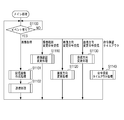
- the control unit 1001 waits for an event (S1100).
- the imaging apparatus 1000 determines that there is an event when an image acquisition, imaging range change command reception, image direction change command reception, coordinate direction change command reception, or command hold time-out event occurs.
- the imaging apparatus 1000 executes the processing from step S1101 to step S1102.
- the image acquisition event is an event that occurs when the imaging apparatus 1000 receives an image acquisition request for acquiring a captured image captured by the imaging apparatus 1000 from the client 3000.
- control unit 1001 of the imaging apparatus 1000 performs distribution image creation processing (S1101). Details of the distribution image creation processing will be described later with reference to FIG. 4A.
- control unit 1001 When the delivery image creation processing is completed, the control unit 1001 performs transmission processing (S1102). In the transmission process, the control unit 1001 transmits the distribution image created in the distribution image creation process in step S1101 to the client 3000 requesting the video distribution from the imaging apparatus 1000 via the communication unit 1004. After performing the transmission process, the control unit 1001 returns to step S1100 to perform the process.
- the control unit 1001 of the imaging apparatus 1000 when receiving the imaging range change command shown in FIG. 5A from the client 3000, the control unit 1001 of the imaging apparatus 1000 performs an imaging range change process to be described later with reference to FIG. 4B (S1110).
- control unit 1001 when the control unit 1001 receives the image direction change command shown in FIG. 5B from the client 3000, the control unit 1001 performs an image direction change process to be described later with reference to FIG. 4C (S1120).
- control unit 1001 when the control unit 1001 receives the coordinate direction change command shown in FIG. 5C from the client 3000, the control unit 1001 performs coordinate direction change processing described later with reference to FIG. 4D (S1130).
- step S1110 When the processing in step S1110, step S1120, step S1130, or step S1140 is completed, the control unit 1001 returns to step S1100 to perform processing.
- the control unit 1001 refers to the memory 1002 and determines an image direction parameter (S1200).
- the image direction parameter is ON (Yes in S1200)
- the control unit 1001 inverts the captured image (rotates 180 degrees) as illustrated in the captured image 1072 in FIG. 7 and stores the captured image stored in the memory 1002 Is overwritten and the distribution image creation processing is terminated (S1201). If the image direction parameter is OFF (No in S1200), the control unit 1001 ends the distribution image creation process without performing the process.
- the control unit 1001 refers to the memory 1002 and acquires the coordinate direction parameter of the coordinate direction change command shown in FIG. 5C (S1300). Further, the control unit 1001 refers to the memory 1002 and acquires arguments (pan coordinates, tilt coordinates, zoom coordinates) of the imaging range change command illustrated in FIG. 5A (S1301).
- the control unit 1001 inputs the acquired coordinate direction parameters, pan coordinates, tilt coordinates, and zoom coordinates to the imaging control unit 1006 (S1302).
- the imaging control unit 1006 operates the imaging direction of the imaging unit 1003 by inverting the coordinate system as in the coordinate 1083 illustrated in FIG.
- the imaging control unit 1006 operates the imaging direction of the imaging unit 1003 without inverting the coordinate system as in the coordinate 1082 illustrated in FIG.
- the control unit 1001 ends the imaging range changing process.
- the control unit 1001 refers to the instruction hold queue stored on the memory 1002 shown in FIG. 6A and determines whether or not the memory 1002 is holding execution of the coordinate direction change instruction (S1400). When the memory 1002 does not hold the coordinate direction change command (No in S1400), the control unit 1001 stores the received argument of the image direction change command in the command hold queue of the memory 1002, and executes the image direction change command. Is suspended (S1401).
- the control unit 1001 uses the time measuring unit 1005 to start the instruction hold timer.
- the instruction hold timer is a timer for holding execution of the instruction for a predetermined time after receiving the instruction.
- the timer value of the instruction hold timer may be preset by the user, and may be about several hundred milliseconds to several seconds.
- the control unit 1001 when the control unit 1001 receives an image direction change command without receiving a coordinate direction change command, the control unit 1001 suspends execution of the image direction change command. That is, the execution of the image direction change command is suspended until the coordinate direction change command is received after the image direction change command is received. Accordingly, when the coordinate direction is not changed (coordinate 1082 in FIG. 8) and only the image direction is changed (captured image 1072 in FIG. 7), the coordinate direction (positive direction / inverted direction) and the captured image are changed. It is possible to prevent the image directions (positive direction / inversion direction) from being inconsistent.
- the control unit 1001 deletes the command hold timer (S1410). Then, the control unit 1001 reads the argument of the coordinate direction change command that is pending processing from the command hold queue, and changes the coordinate direction parameter on the memory 1002 (S1411). Subsequently, the control unit 1001 reads an argument of the received image direction change command and changes the image direction parameter on the memory 1002 (S1412). When the process of step S1412 is completed, the control unit 1001 ends the image direction changing process.
- the control unit 1001 executes the coordinate direction change command and the image direction change command.
- the imaging apparatus 1000 can output the captured image in the image direction after the change (the captured image 1072 in FIG. 7), and can change the imaging range based on the coordinates after the change (the coordinates 1083 in FIG. 8). . Accordingly, it is possible to output the captured image in a state where the image direction (positive direction / reversal direction) and the coordinate direction (positive direction / reversal direction) coincide with each other, and to change the imaging range.
- the imaging apparatus 1000 can execute an image direction change command so that the imaging direction always coincides with the coordinate direction.
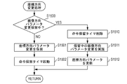
- the control unit 1001 refers to the instruction hold queue on the memory 1002 and determines whether or not the memory 1002 holds execution of the image direction change instruction (S1500). When the memory 1002 does not hold the coordinate direction change command (No in S1500), the control unit 1001 stores the received argument of the coordinate direction change command in the command hold queue, and holds the execution of the coordinate direction command ( S1501). Then, the control unit 1001 uses the time measuring unit 1005 to start an instruction hold timer (S1502).
- the control unit 1001 when the control unit 1001 receives the coordinate direction change command in a state where the image direction change command is not received, the control unit 1001 suspends the execution of the coordinate direction change command. That is, the control unit 1001 suspends the execution of the coordinate direction change command until it receives the image direction change command after receiving the coordinate direction change command. Accordingly, when the image direction is not changed (the captured image 1072 in FIG. 7), only the coordinate direction is changed (the coordinate 1082 in FIG. 8), and the coordinate direction (positive direction / inverted direction) and the captured image are changed. It is possible to prevent the image directions (positive direction / inversion direction) from being inconsistent.
- the control unit 1001 deletes the command hold timer (S1510). Then, the control unit 1001 reads the argument of the image direction parameter change command that is pending processing from the command hold queue, and changes the coordinate direction parameter on the memory 1002 (S1511). Subsequently, the control unit 1001 reads the argument of the received coordinate direction change command, and changes the coordinate direction parameter on the memory 1002 (S1512). Then, the control unit 1001 ends the coordinate direction changing process.
- the control unit 1001 executes the image direction change command and the coordinate direction change command.
- the imaging apparatus 1000 can output the captured image in the image direction after the change (the captured image 1072 in FIG. 7), and can change the imaging range based on the coordinates after the change (the coordinates 1083 in FIG. 8). . Accordingly, it is possible to output the captured image in a state where the image direction (positive direction / reversal direction) and the coordinate direction (positive direction / reversal direction) coincide with each other, and change the imaging range.
- the imaging apparatus 1000 can execute the coordinate direction change command so that the image direction and the coordinate direction always coincide.
- the control unit 1001 refers to the instruction hold queue on the memory 1002 and deletes the instructions held in the queue. Then, the control unit 1001 ends the instruction hold timeout process.
- the control unit 1001 does not execute the received command. Accordingly, only one of the image direction change command and the coordinate direction change command is not executed, and therefore the direction of the coordinate system (positive direction / reversal direction) of the imaging apparatus 1000 and the image direction of the captured image (positive direction / It is possible to prevent the inversion direction) from being inconsistent.
- the imaging apparatus 1000 can execute the coordinate direction change command so that the imaging direction always coincides with the coordinate direction.
- the imaging apparatus 1000 can prevent a state where only one of the image direction and the coordinate direction is changed. As a result, when the user changes the imaging range while viewing the captured image distributed from the imaging apparatus 1000, the direction of the distributed captured image can coincide with the direction of the command for changing the imaging range. . Accordingly, it is possible to change the imaging range in accordance with the user's intention.
- the control unit 1001 executes the pending command. It is good to do. In this way, if the user wants to execute either the image direction change command or the coordinate direction change command, the command is executed after a predetermined time has elapsed since the command was received. Can do. Further, when the user desires to execute both the image direction change command and the coordinate direction change command, the coordinates of the imaging apparatus 1000 from when one command is received until the other command is received. It is possible to prevent a mismatch between the system direction and the image direction of the captured image.
- a normal response or an error response may be transmitted to the requesting client in response to each command shown in FIGS. 5A to 5C described in the first embodiment. That is, when the imaging apparatus 1000 normally processes a command from the client 3000, the imaging device 1000 transmits a normal response to the client 3000 that is the command request source. If the command from the client 3000 is not processed normally, the imaging apparatus 1000 transmits an error response to the client 3000 that is the command request source. This makes it easier for the client to grasp the processing result and processing timing of each command.
- the control unit 1001 When the third instruction having the same content as the instruction held by the receiving unit is received while the execution of the image direction changing instruction or the coordinate direction changing instruction is held in this way, the control unit 1001 The third instruction can be prevented from being executed.
- the communication unit 1004 receives the first command from the first control device until the first command is received until the other command is received from the first control device.
- the command received from the second control device can be prevented from being executed.
- the control unit 1001 Does not execute the pending image direction change command or coordinate direction change command, and can hold the execution of the third command until the other command is received.
- Example 2 In the second embodiment, a case where the present invention is applied to an imaging apparatus having a so-called digital PTZ (Pan Tilt Zoom) function that changes a captured image displayed on a client by changing a region in which the captured image is trimmed will be described.
- digital PTZ Pan Tilt Zoom
- FIG. 1C shows an imaging apparatus 2000 according to the second embodiment.
- the imaging apparatus 2000 according to the present embodiment does not include the pan driving mechanism 1101, the tilt driving mechanism 1102, and the zoom mechanism 1103.
- the imaging apparatus 2000 does not have the imaging control unit 1006 as compared with the imaging apparatus 1000 in the first embodiment.
- the control unit 1001 of the imaging apparatus 2000 generates a captured image obtained by cutting out a part of the captured image captured by the imaging unit 1003 and transmits the captured image to the client 3000 via the communication unit 1004.
- the imaging apparatus 2000 receives an instruction about the cutout position of the captured image from the client 3000 as a trimming parameter.
- the trimming parameter is a parameter for specifying a portion to trim a captured image generated by the imaging unit 1003 and distribute to a client.
- An example of trimming parameters will be described with reference to FIG. 6B.
- the trimming parameters shown in FIG. 6B are composed of two points (x1, y1) and (x2, y2) represented by an X coordinate indicating the horizontal direction of the captured image and a Y coordinate indicating the vertical direction.
- the corner rectangle indicates the range to be trimmed.
- the imaging apparatus 2000 can receive an image coordinate direction change command from the client 3000.
- An example of the image coordinate direction change command is shown in FIG. 5D.
- the client 3000 can change both the direction of the captured image distributed by the imaging apparatus 2000 and the direction of the coordinates of the imageable range. Details about the change of the image direction and the change of the coordinate direction are the same as the contents described with reference to FIGS. 5B and 5C in the embodiment, and the description is omitted.
- the imaging device 2000 when the imaging apparatus 2000 normally processes the command from the client 3000, the imaging device 2000 transmits a normal response to the client 3000 that is the command request source.
- the imaging apparatus 2000 transmits an error response to the client 3000 that is the command request source.
- An example of a normal response is shown in FIG. 5E.
- An example of an error response is shown in FIG. 5F.
- FIGS. 9 and 10A to 10C show a program for causing the control unit 1001 to execute the procedure shown in FIGS. 9 and 10A to 10C.
- the processor built in the control unit 1001 of the imaging apparatus 1000 is a computer, and executes a program read from the memory 1002 built in the imaging apparatus 1000.
- the control unit 1001 waits for an event (S2100).
- the imaging apparatus 2000 receives an event when an image coordinate direction change command reception event occurs in addition to image acquisition, imaging range change command reception, image direction change command reception, coordinate direction change command reception, and command hold timeout. Judge that there is.
- the control unit 1001 of the imaging apparatus 2000 performs distribution image creation processing (S2101).
- the control unit 1001 selects a captured image according to the trimming parameters shown in FIG. 6B when the image direction parameter is OFF (forward direction) (No in step S1200 in FIG. 4A). Trim.
- the image direction parameter is ON (inversion direction) (Yes in S1200)
- the control unit 1001 changes the image direction in accordance with the image direction parameter in step S1201 illustrated in FIG. Trim.
- the control unit 1001 overwrites the captured image stored in the memory 1002 with the trimmed captured image, and ends the distribution image creation process.
- control unit 1001 When the delivery image creation processing is completed, the control unit 1001 performs transmission processing (S2102). In the transmission processing, the control unit 1001 transmits the distribution image trimmed in the distribution image creation processing in step S1101 to the client 3000 requesting video distribution from the imaging apparatus 1000 via the communication unit 1004. After performing the transmission process, the control unit 1001 returns to step S1100 to perform the process.
- the control unit 1001 upon receiving an imaging range change command from the client 3000, the control unit 1001 performs an imaging range change process (S2110).
- the imaging range change command is used to change the range in which an image is cut out of the imaging range.
- the imaging range changing process in the present embodiment will be described with respect to differences from the process described with reference to FIG. 4B in the first embodiment.
- the control unit 1001 according to the present embodiment calculates the trimming parameters in step S1302 in FIG. 4B after performing the processes in steps S1300 and S1301 shown in FIG. 4B. That is, when the acquired coordinate direction parameter is ON (inversion direction), the control unit 1001 determines the trimming range by inverting the coordinate system as indicated by the coordinates 1083 in FIG. On the other hand, when the acquired coordinate direction parameter is OFF (positive direction), the control unit 1001 determines the trimming range without inverting the coordinate system like the coordinate 1082 in FIG.
- the control unit 1001 obtains the position of the trimming range in coordinates in units of pixels.
- the coordinates 2082 and the coordinates 2083 in FIG. 8 are coordinates represented by an X coordinate and a Y coordinate with the lower left vertex as an origin and a pixel as a unit.
- the control unit 1001 has two pixel coordinates (x1, y1) and (x2) on the captured image corresponding to the two vertices forming the diagonal of the determined trimming range. , Y2) are calculated as trimming parameters.
- the control unit 1001 stores the calculated trimming parameter in the memory 1002. Then, the control unit 1001 ends the imaging range changing process.
- control unit 1001 when the control unit 1001 according to the present embodiment receives the image direction change command from the client 3000, the control unit 1001 performs an image direction change process to be described later with reference to FIG. 10A (S2120).
- control unit 1001 when receiving the coordinate direction change command from the client 3000, the control unit 1001 according to the present embodiment performs a coordinate direction change process to be described later with reference to FIG. 10B (S2130).
- the control unit 1001 performs a command hold time-out process to be described later with reference to FIG.
- control unit 1001 when receiving the image coordinate direction change command shown in FIG. 4C from the client 3000, the control unit 1001 according to the present embodiment performs an image coordinate direction change process to be described later with reference to FIG. 10C (S2111). When the process of step S2111 ends, the control unit 1001 returns to step S2100 to perform the process.
- the control unit 1001 refers to the instruction hold queue on the memory 1002 and determines whether the coordinate direction change command requested from the transmission source client (hereinafter, the current transmission source) of the pending image direction change command is held. (S2400). If the coordinate direction change command from the current transmission source is not pending (No in S2400), the control unit 1001 determines whether the image direction change command requested from the current transmission source is pending (S2401). The determination in step S2401 is performed by referring to the instruction hold queue on the memory 1002. If it is pending (in the case of Yes in S2401), the control unit 1001 transmits an error response to the image direction change command currently being received (S2420).
- the control unit 1001 when the control unit 1001 receives the image direction change command again while holding the execution of the image direction change command, it does not execute the image direction change command received later. In this way, the imaging apparatus 1000 according to the present embodiment can prevent the image direction change command from being executed repeatedly.
- control unit 1001 when the control unit 1001 receives the image direction change command again while holding the execution of the image direction change command, the control unit 1001 receives the coordinate direction change command without executing the held image direction change command. Until then, execution of the image direction change command received later can be suspended. Even in this case, it is possible to prevent the image direction change command from being executed repeatedly.
- the control unit 1001 stores the received image direction change command argument in the command hold queue together with the information indicating the transmission source. The execution of the change command is suspended (S2402). Then, the control unit 1001 uses the time measuring unit 1005 to start an instruction hold timer for the current transmission source (S2403).
- the control unit 1001 of this embodiment when the control unit 1001 of this embodiment receives an image direction change command, the control unit 1001 suspends execution of the image direction change command in a state where the coordinate direction change command is not received from the client that transmitted the command. . Therefore, when the coordinate direction is not changed (coordinate 2082 in FIG. 8) and only the image direction is changed (captured image 1072 in FIG. 7), the coordinate direction (positive direction / inverted direction) and the captured image are changed. It is possible to prevent the image directions (positive direction / inversion direction) from being inconsistent.
- the control unit 1001 deletes the command suspension timer for the current transmission source (S2410).
- control unit 1001 reads out the argument of the coordinate direction change command in which the transmission source whose processing is pending is the current transmission source, and changes the coordinate direction parameter on the memory 1002 (S2411).
- control unit 1001 reads the argument of the currently received image direction change command and changes the image direction parameter on the memory 1002 (S2412).
- control unit 1001 transmits, to the current transmission source, the normal response shown in FIG. 5E to the coordinate direction change command that was pending in step S2411 (S2413).
- control unit 1001 transmits a normal response to the image direction change command executed in step S2412 to the current transmission source (S2414).
- control unit 1001 refers to the instruction hold queue and transmits an error response shown in FIG. 5F to each transmission source for all the held instructions (S2415).
- the control unit 1001 executes the coordinate direction change command and the image direction change command.
- the imaging apparatus 1000 can output the captured image in the image direction after the change (the captured image 1072 in FIG. 7), and can change the imaging range based on the coordinates after the change (the coordinates 1083 in FIG. 8). . Accordingly, it is possible to output the captured image in a state where the image direction (positive direction / reversal direction) and the coordinate direction (positive direction / reversal direction) coincide with each other, and change the imaging range.
- the imaging apparatus 1000 can execute an image direction change command so that the imaging direction always coincides with the coordinate direction.
- step S2400 and step S2401 the control unit 1001 determines whether the command is a command issued by the current transmission source. In this way, the execution of one of the previously received commands can be suspended until both the image direction change command and the coordinate direction change command are issued to the imaging apparatus 1000 by the same client. Thereby, it is possible to perform control for each client so that both the instructions are executed so that the image direction and the coordinate direction coincide with each other.
- step S2400 and step S2401 the control unit 1001 may not determine whether the command is a command issued by the current transmission source. In this case, both commands are executed when the pair of commands are issued to the imaging apparatus without distinguishing the clients. Therefore, even when a plurality of clients issue an image direction change command or a coordinate direction change command, the imaging apparatus 1000 can execute both commands so that the image direction matches the coordinate direction.
- the control unit 1001 refers to the instruction hold queue on the memory 1002, and determines whether or not the image direction change command requested from the transmission source of the coordinate direction change command currently being processed is held (S2500). When the image direction change command from the current transmission source is not on hold (No in S2500), the control unit 1001 determines whether the coordinate direction change command requested from the current transmission source is on hold (S2501). The determination in step S2501 is performed by referring to the instruction hold queue on the memory 1002. If it is pending (Yes in S2501), the control unit 1001 transmits an error response to the coordinate direction change command currently being received (S2520).
- the imaging apparatus 1000 can prevent the coordinate direction change command from being executed repeatedly.
- an error response may be transmitted to the previously received instruction, and the newly received instruction may be newly suspended. Even in this case, it is possible to prevent the coordinate direction change command from being executed repeatedly.
- control unit 1001 If the coordinate direction change command from the current transmission source is not pending (Yes in S2501), the control unit 1001 stores the received coordinate direction change command argument together with the current transmission source in the command hold queue, and the image direction change command. Is suspended (S2502).
- the control unit 1001 when the control unit 1001 receives the coordinate direction change command in a state where the image direction change command is not received, the control unit 1001 suspends the execution of the coordinate direction change command. Accordingly, when the image direction is not changed (the captured image 1072 in FIG. 7), only the coordinate direction is changed (the coordinate 2082 in FIG. 8), and the coordinate direction (positive direction / inverted direction) and the captured image are changed. It is possible to prevent the image directions (positive direction / inversion direction) from being inconsistent.
- control unit 1001 uses the time measuring unit 1005 to start an instruction hold timer for the current transmission source (S2503).
- the control unit 1001 uses the time measuring unit 1005 to delete the command pending timer for the current transmission source. (S2510).
- control unit 1001 reads an argument of an image direction change command in which the current transmission source whose processing is pending is a transmission source from the command hold queue, and changes the image direction parameter on the memory 1002 (S2511).
- control unit 1001 reads the argument of the coordinate direction change command currently received and updates the coordinate direction parameter on the memory 1002 (S2512).
- control unit 1001 transmits, to the current transmission source, the normal response shown in FIG. 5E in response to the pending image direction change command executed in step S2411 (S2513).
- control unit 1001 transmits a normal response to the coordinate direction change command executed in step S2512 to the current transmission source (S2514).
- control unit 1001 refers to the instruction hold queue and transmits an error response illustrated in FIG. 5F to each transmission source with respect to all the held instructions (S2515).
- the control unit 1001 executes the image direction change command and the coordinate direction change command.
- the imaging apparatus 1000 can output the captured image in the image direction after the change (the captured image 1072 in FIG. 7), and change the imaging range based on the coordinates after the change (the coordinates 2083 in FIG. 8). . Accordingly, it is possible to output the captured image in a state where the image direction (positive direction / reversal direction) and the coordinate direction (positive direction / reversal direction) coincide with each other, and change the imaging range.
- the imaging apparatus 1000 can execute the coordinate direction change command so that the image direction and the coordinate direction always coincide.
- step S2500 and step S2501 the control unit 1001 determines whether the command is a command issued by the current transmission source. In this way, the execution of one of the previously received commands can be suspended until both the image direction change command and the coordinate direction change command are issued to the imaging apparatus 1000 by the same client. Thereby, it is possible to perform control for each client so that both the instructions are executed so that the image direction and the coordinate direction coincide with each other.
- step S2500 and step S2501 the control unit 1001 may not determine whether the command is a command issued by the current transmission source. In this case, both commands are executed when the pair of commands are issued to the imaging apparatus without distinguishing the clients. Therefore, even when a plurality of clients issue an image direction change command or a coordinate direction change command, the imaging apparatus 1000 can execute both commands so that the image direction matches the coordinate direction.
- the control unit 1001 processes a command for which a pending timeout has occurred and transmits a normal response. Alternatively, the control unit 1001 may transmit an error response without processing a command for which a pending timeout has occurred.
- control unit 1001 processes a command for which a pending timeout has occurred and transmits a normal response.
- the control unit 1001 refers to the time-out event from the time measuring unit 1005, and determines which source is the time-out. Then, the control unit 1001 refers to the instruction hold queue on the memory 1002, acquires the instruction that is the determined transmission source (current transmission source) among the held instructions, and executes the acquired instruction. Subsequently, the control unit 1001 transmits a normal response to the executed command to the current transmission source. Then, the control unit 1001 finishes the instruction hold timeout process. In this way, even when the coordinate direction and the image direction of the captured image do not coincide with each other by executing the command, the command from the client can be executed as instructed after a predetermined time has elapsed. it can.
- control unit 1001 when transmitting an error response without processing a command for which a pending timeout has occurred will be described.
- the control unit 1001 refers to the time-out event from the time measuring unit 1005, and determines which source is the time-out. Next, the control unit 1001 refers to the instruction hold queue on the memory 1002 and deletes the instruction that is the determined transmission source (current transmission source) from the queue among the pending instructions. Subsequently, the control unit 1001 transmits an error response to the deleted command to the current transmission source. Then, the control unit 1001 finishes the instruction hold timeout process. In this way, if the coordinate direction does not match the image direction of the captured image by executing the command, it is possible to prevent the command from not being executed.
- control unit 1001 does not send a normal response to the client until receiving the other command after receiving one command of the image direction change command or the coordinate direction change command from the client. To. By doing in this way, it can be made easy for the user to understand that the instruction is suspended.
- the control unit 1001 refers to the instruction hold queue on the memory 1002 and determines whether there is a pending instruction (S2700). When there is a pending command (Yes in S2700), the control unit 1001 uses the timekeeping unit 1005 to delete all command pending timers that are activated (S2710). Subsequently, the control unit 1001 transmits an error response to all the instructions held in the instruction hold queue to each transmission source (S2711). Then, the control unit 1001 shifts the processing to step S2701 described later.
- step S2701 the control unit 1001 updates both the image direction parameter and the coordinate direction parameter on the memory 1002 in accordance with the image / coordinate direction argument of the received image coordinate direction change command.
- step S2702 the control unit 1001 transmits a normal response to the transmission source of the image coordinate direction change command (S2702).
- control unit 1001 when the control unit 1001 receives the image coordinate direction change command while holding the execution of the image direction change command or the coordinate direction change command, the control unit 1001 executes the image coordinates without executing the held command. Execute a direction change command.
- the imaging apparatus 1000 can output the captured image in the image direction after the change (the captured image 1072 in FIG. 7), and change the imaging range based on the coordinates after the change (the coordinates 2083 in FIG. 8). . Accordingly, it is possible to output the captured image in a state where the image direction (positive direction / reversal direction) and the coordinate direction (positive direction / reversal direction) coincide with each other, and change the imaging range.
- the imaging apparatus 2000 can prevent the state of the image and the direction of the coordinates of the imageable range from changing to one side. In addition, it is possible to appropriately process image direction change commands and coordinate direction change commands received from a plurality of clients, and to return normal / error responses.
- the processing when a plurality of clients 3000 are connected to the imaging apparatus 1000 via the network 3020 has been described. Further, in the present embodiment, the processing in the case of performing a normal response indicating that the command has been executed normally or an error response indicating that the command has not been executed with respect to the command from the client 3000 has been described. Further, in the present embodiment, the processing when the image coordinate direction change command is received from the client 3000 has been described. These processes are not limited to being applied to an imaging apparatus having a so-called digital PTZ function as in the present embodiment, and can also be applied to the imaging apparatus described in the first embodiment.
- Example 3 In the third embodiment, a client application for the client 3000 to transmit an image direction change command illustrated in FIG. 5B or a coordinate direction change command illustrated in FIG. 5C to the imaging apparatus 1000 will be described.
- FIGS. 11A and 11B Processing when the client 3000 transmits a coordinate direction change command or an image direction change command to the imaging apparatus 1000 will be described with reference to the flowcharts shown in FIGS. 11A and 11B.
- the control unit 3001 of the client 3000 includes a processor
- the processing flow of FIGS. 11A and 11B shows a program for causing the control unit 3001 of the client 3000 to execute the procedure shown in FIGS. 11A and 11B.
- the processor built in the control unit 3001 is a computer, and executes a program read from the memory 3002 built in the client 3000.
- the control unit 3001 determines whether transmission of the image direction inversion command is suspended (S3100). If transmission of an image direction inversion command is pending (Yes in S3100), the control unit 3001 transmits an image direction inversion command (S3110). Subsequently, the control unit 3001 transmits a coordinate direction inversion command, and ends the coordinate direction inversion button pressing process (S3111).
- the control unit 3001 causes the display unit 3010 to display a display for inquiring the user whether to reverse the image direction. .
- the control unit 3001 can display a message “Do you want to reverse the image direction?” On the display unit 3010 to allow the user to select Yes or No.
- an instruction to invert the image is received (Yes in S3102), the above-described processing in step S3110 and processing in step S3111 are executed.
- control unit 3001 suspends the transmission of the coordinate direction reversal command and ends the coordinate direction reversal button pressing process (S3103).
- control unit 3001 may cause the display unit 3010 to display a notification to suspend transmission of the coordinate direction reversal command.
- step S3102 By making an inquiry in step S3102, the user can be instructed to make the image direction of the imaging apparatus 1000 coincide with the coordinate direction. Further, in the inquiry in step S3102, the user can select whether or not to perform an image direction change command, so that a command suitable for the user's intention can be issued.
- the control unit 3001 determines whether transmission of the coordinate direction reversal command is suspended (S3200). If it is on hold (Yes in S3200), the control unit 3001 transmits an image direction inversion command (S3210). Subsequently, the control unit 3001 transmits a coordinate direction inversion command, and ends the coordinate direction inversion button pressing process (S3211).
- the control unit 3001 When the transmission of the coordinate direction reversal command is not pending (No in S3200), the control unit 3001 causes the display unit 3010 to display a display for inquiring the user whether to reverse the coordinate direction. . For example, the control unit 3001 can display a message “Do you want to reverse the coordinate direction?” On the display unit 3010 to allow the user to select Yes or No. If an instruction to invert the coordinates is received (Yes in S3202), the process of Step S3210 and the process of Step S3211 are executed.
- control unit 3001 suspends transmission of the image direction reversal command, and ends the image direction reversal button pressing process (S3203).
- the control unit 3001 may cause the display unit 3010 to display a notification that the transmission of the image direction inversion command is suspended.
- step S3202 By making an inquiry in step S3202, the user can be instructed to make the image direction of the imaging apparatus 1000 coincide with the coordinate direction. Further, in the inquiry in step S3202, the user can select whether or not to perform a coordinate direction change command, so that a command suitable for the user's intention can be issued.
- the control unit 3001 receives the instruction to transmit one command of the image direction inversion command or the coordinate direction inversion command to the imaging apparatus 1000 until the instruction to transmit the other command to the imaging apparatus 1000 is received.
- the transmission of the instruction received the instruction to transmit to 1000 is suspended.
- the client 3000 can prevent the direction of the image and the direction of the coordinates of the imageable range from being changed in one state in the imaging apparatus to be controlled. Therefore, when the imaging range is changed while viewing the captured image distributed from the imaging apparatus 1000, the imaging range can be changed in the same direction as the direction of the distributed captured image. Therefore, it is possible to change the imaging range according to the user's intention.
- the embodiment is not necessarily limited to the above, and may be partially changed.
- the commands in FIGS. 5B and 5C from a certain client when one of the commands in FIGS. 5B and 5C from a certain client is held and any command is received from a different client, the commands are also held in the same manner. This is not the case.
- An error response may be transmitted for commands from different clients, and a plurality of commands may not be suspended. In this way, until one of the image direction change command or the coordinate direction change command is received from the first client and the other command is received from the first client, the control unit 1001 receives from the second client. The received command can be prevented from being executed.
- the command from the second client is executed between the time when the first client sends the image direction change command and the time when the coordinate direction change command is issued, and a change unintended by the user of the first client is made. You can prevent it from being done. Therefore, the first client can reliably issue a pair of image direction change commands and coordinate direction change commands to the imaging apparatus. Therefore, the imaging apparatus 1000 can output a captured image in a state where the image direction and the coordinate direction always match, and can change the imaging range.
- the interface for changing the image direction and changing the coordinate direction has been described as specifying either the normal direction or the reverse direction, but this is not restrictive.
- the interface may be designated every 90 degrees or once.
- both the image direction change command and the coordinate direction change command are received, the direction specified by each command is not determined and both commands are processed. This is not the case. Both instructions may be processed only when the direction designation of the previously held instruction matches the instruction designation received later. In this case, if the direction designation of the pending instruction does not match the instruction designation received later, an error response may be transmitted to the latter instruction.
- the present invention can also be realized by executing the following processing. That is, software (program) that realizes the functions of the above-described embodiments is supplied to a system or apparatus via a network or various storage media, and a computer (or CPU, MPU, or the like) of the system or apparatus reads the program. It is a process to be executed.
Landscapes
- Engineering & Computer Science (AREA)
- Multimedia (AREA)
- Signal Processing (AREA)
- Studio Devices (AREA)
- Closed-Circuit Television Systems (AREA)
Abstract
撮像手段と、前記撮像手段の撮像範囲における撮像方向又は領域を表すための座標系を保持する保持手段と、前記撮像手段が撮像した撮像画像又は前記撮像範囲上の領域から切り出した撮像画像を所定の角度回転させる第1の命令と、前記保持手段に保持された前記座標系を原点を中心として前記所定の角度回転させる第2の命令と、前記座標系における前記撮像方向を特定するための特定情報とを受信する受信手段と、前記特定情報により特定される前記撮像方向に前記撮像手段の撮像方向を変更する制御を行う変更制御手段と、前記受信手段が前記第1の命令又は前記第2の命令のうち一方の命令を受信してから他方の命令を受信するまでは前記受信手段が受信した前記第1の命令又は前記第2の命令の実行を保留する制御手段とを有することを特徴とする。
Description
本発明は、撮像画像をネットワークを介して端末に配信可能な撮像装置に関し、特に、撮像装置が端末に提供する複数のインタフェースの排他処理に関する。
従来、雲台を動作させることにより撮像する方向を変更する撮像装置が知られている。また、撮像装置にネットワークを介して接続された制御装置から送信される指示に従って、撮像装置が撮像する方向を変更する撮像装置が知られている。このような撮像装置では、撮像装置の設置状態を変更した場合、変更前と後では同一の命令に応じて撮像装置が撮像する方向が異なる。
例として、撮像装置を正立させて設置した状態から、撮像装置を倒立させて天井等に設置した状態に設置状態を変更する場合について説明する。正立して設置された撮像装置の撮像方向を上方向に向けさせるための命令を、倒立して設置された撮像装置に対して行うと、撮像装置は撮像方向を下方向に向けるように動作する。このようにして、撮像装置の設置状態が正立から倒立に変更された場合、同一の命令に対して撮像装置が撮像する方向の上下及び左右が逆転する。
そこで、撮像装置が撮像する方向を変更させるための制御プログラムを複数保持し、撮像装置が設置される向きに応じて使用する制御プログラムを切り換える撮像システムが知られている(例えば、特許文献1)。この撮像システムは、制御プログラムを切り換えることにより、撮像方向を座標で表すための座標系を切り換える。これにより、設置状態に関わらず撮像装置は特定の命令に対して一定の方向に撮像方向を向けることができる。
撮像装置が撮像した撮像画像を制御装置が受信して表示する場合、撮像装置の設置状態の変更は、制御装置において表示される撮像画像の向きにも影響する。従って、撮像された撮像画像の向きも変更できることが望ましい。例えば、撮像装置の設置状態を正立状態から倒立状態に変更した場合、制御装置に表示される撮像画像の上下左右が逆転する。そこで、撮像装置が倒立状態で撮像した撮像画像を180度回転させて制御装置において表示させることにより、正立状態で撮像した撮像画像と上下左右が一致した撮像画像を表示させることができる。
このように制御装置において表示させる撮像画像の向きを変更するインタフェースと、上述した撮像方向を制御するための座標系を変更するインタフェースとは、それぞれ別々の命令として定義される場合がある。このような撮像装置において、表示させる撮像画像の向きと撮像方向を制御するための座標系の向き双方を変更しようとする場合、表示させる撮像画像における上下及び左右の向きと、座標系における上下及び左右の向きが一致しない状態となる場合がある。例えば、撮像画像の向きを変更するための命令と座標系の向きを変更するための命令のうち、先に受信した一方の命令が処理され、他方の命令が未処理である場合、撮像画像の向きと座標系の向きが不一致となる。
この状態において、ユーザが配信されている撮像画像を見ながら撮像方向の変更の命令を撮像装置に送信すると、ユーザが期待する方向とは異なる方向に雲台が動作してしまうという課題がある。同様の課題は、撮像画像又は座標系の向きを180度回転させる場合に限られず、撮像画像の向き又は座標の向きを任意の角度に回転させる場合に生じる。
上記課題を解決するために、本発明による撮像装置は例えば以下の構成を有する。すなわち、撮像手段と、前記撮像手段の撮像方向を表すために用いる座標系を保持する保持手段と、前記撮像手段が撮像した撮像画像を所定の角度回転させる第1の命令と、前記保持手段に保持された前記座標系を原点を中心として前記所定の角度回転させる第2の命令と、前記座標系における前記撮像方向を特定するための特定情報とを受信する受信手段と、前記特定情報により特定される前記撮像方向に前記撮像手段の撮像方向を変更する制御を行う変更制御手段と、前記受信手段が前記第1の命令又は前記第2の命令のうち一方の命令を受信してから他方の命令を受信するまでは前記受信手段が受信した前記第1の命令又は前記第2の命令の実行を保留する制御手段とを有することを特徴とする。
または、本発明による撮像装置は例えば以下の構成を有する。すなわち、撮像手段と、前記撮像手段の撮像範囲における領域を表すために用いる座標系を保持する保持手段と、前記撮像範囲上の領域から切り出した撮像画像を所定の角度回転させる第1の命令と、前記保持手段に保持された前記座標系を原点を中心として前記所定の角度回転させる第2の命令と、前記撮像範囲から前記撮像画像を切り出す領域を前記座標系において特定するための特定情報とを受信する受信手段と、前記特定情報により特定される前記座標系における領域の前記撮像画像を切り出す切出手段と、前記受信手段が前記第1の命令又は前記第2の命令のうち一方の命令を受信してから他方の命令を受信するまでは前記受信手段が受信した前記第1の命令又は前記第2の命令の実行を保留する制御手段とを有することを特徴とする。
または、本発明による制御装置は例えば以下の構成を有する。すなわち、撮像手段の撮像方向を表すために用いる座標系を保持する保持手段を有する撮像装置を制御する制御装置であって、前記座標系における撮像方向を特定するための特定手段と、前記特定手段が特定した撮像方向において前記撮像手段が撮像した撮像画像を所定の角度回転させる第1の命令及び前記保持手段に保持された前記座標系を原点を中心として前記所定の角度回転させる第2の命令を前記撮像装置に対して送信する制御を行う送信制御手段と、前記送信制御手段が前記第1の命令又は前記第2の命令のうち一方の命令を前記撮像装置に送信する指示を受けてから他方の命令を前記撮像装置に送信する指示を受けるまでは、前記送信制御手段は前記撮像装置に送信する指示を受けた前記命令の送信を保留することを特徴とする。
または、本発明による制御装置は例えば以下の構成を有する。すなわち、撮像手段の撮像範囲における領域を表すために用いる座標系を保持する保持手段を有する撮像装置を制御する制御装置であって、前記座標系における領域を特定するための特定手段と、前記特定手段が特定した前記座標系における領域に応じた前記撮像範囲上の領域の撮像画像を所定の角度回転させる第1の命令及び前記保持手段に保持された前記座標系を原点を中心として前記所定の角度回転させる第2の命令を前記撮像装置に対して送信する制御を行う送信制御手段と、前記送信制御手段が前記第1の命令又は前記第2の命令のうち一方の命令を前記撮像装置に送信する指示を受けてから他方の命令を前記撮像装置に送信する指示を受けるまでは、前記送信制御手段は前記撮像装置に送信する指示を受けた前記命令の送信を保留することを特徴とする。
本発明によれば、制御装置において表示させる撮像画像の向きを変更する命令と、撮像装置の撮像方向を制御するために用いる座標系の向きを変更する命令とを独立して撮像装置が受信する場合でも、ユーザが意図した方向に撮像方向を変更できる。
また本発明によれば、制御装置において表示させる撮像画像の向きを変更する命令と、撮像装置の撮像方向を制御するために用いる座標系の向きを変更する命令とを独立して制御装置が送信する場合でも、ユーザが意図した方向に撮像方向を変更できる。
以下、本発明をその好適な実施形態に基づいて詳細に説明する。なお、以下の実施形態において示す構成は一例に過ぎず、本発明は図示された構成に限定されるものではない。
(実施例1)
本実施例に係る撮像システムの構成を図1Aに示す。本実施例に係る撮像システムでは、撮像装置1000がネットワーク3020を介してクライアント3000に接続される。撮像装置1000は撮像した撮像画像をネットワーク3020を介してクライアント3000に配信する。
本実施例に係る撮像システムの構成を図1Aに示す。本実施例に係る撮像システムでは、撮像装置1000がネットワーク3020を介してクライアント3000に接続される。撮像装置1000は撮像した撮像画像をネットワーク3020を介してクライアント3000に配信する。
ネットワーク3020は、例えばEthernet(登録商標)等の通信規格を満足する複数のルータ、スイッチ、ケーブル等から構成される。本発明においては撮像装置1000、クライアント3000間の通信を行うことができるものであればその通信規格、規模、構成を問わない。例えば、ネットワーク3020はインターネットや有線LAN(Local Area Network)、無線LAN(Wireless LAN)、WAN(Wide Area Network)等により構成されてもよい。
クライアント3000は、撮像装置1000に対して命令を送信する。クライアント3000は、撮像装置1000の撮像方向又は画角を変更するための命令を送信する。また、クライアント3000は、撮像装置1000の撮像範囲における位置を表すために用いる座標系を原点を中心として回転させる命令を送信する。さらにクライアント3000は、撮像装置1000が撮像した撮像画像を表示させるための表示部3010を有し、表示部3010において表示される撮像画像を撮像装置1000において回転させるための命令を送信する。
撮像装置1000は、クライアント3000から受信した撮像方向を変更するための命令に応じて撮像方向を変更する。また、撮像装置1000は、クライアント3000から受信した画角を変更するための命令に応じて画角を変更する。本実施例に係る撮像装置1000が撮像方向又は画角を変更するための駆動機構について図1Bを用いて説明する。パン駆動機構1101は撮像装置1000の撮像方向をパン方向に変更させる。また、チルト駆動機構1102は撮像装置1000の撮像方向をチルト方向に変更する。さらに、ズーム機構1103は撮像装置1000の画角を変更させる。
本実施例に係る撮像装置1000の内部構成を図2Aに示す。図2Aにおいて、制御部1001は、撮像装置1000の全体の制御を行う。制御部1001は、例えばCPU(Central Processing Unit)により構成され、後述のメモリ1002に記憶されたプログラムを実行する。
メモリ1002は、制御部1001が実行するプログラム格納領域、プログラム実行中のワーク領域、後述する撮像部1003が生成する撮像画像の格納領域等、データの格納領域として使用される。またメモリ1002は、撮像装置1000の撮像範囲における位置を表すために用いる座標系を保持する。またメモリ1002は、後述の通信部1004が受信した命令の実行を保留するための命令保留キューを保持する。
撮像部1003は、被写体を撮影して取得したアナログ信号をデジタルデータに変換する。また撮像部1003は、ADCT(Adaptive Discrete Cosine Transform、適応離散コサイン変換)等によりデータの圧縮処理を行って撮像画像の撮像画像を生成し、メモリ1002に出力する。撮像部1003は、撮像画像をメモリ1002に出力した後、制御部1001に画像取得イベントを送信する。
通信部1004は、図5Aに示す撮像範囲変更命令、図5Bに示す画像方向変更命令、及び、図5Cに示す座標方向変更命令をクライアント3000から受信する。通信部1004は図5A~5Cに示す命令を受信すると、制御部1001に対し受信イベントを送信する。また通信部1004は、図5A~5Cの命令に対する応答をクライアントへ送信する。本実施例では、通信部1004は、受信した命令が正常に実行されることを示すための応答である正常応答、又は、受信した命令が実行されないことを示すための応答であるエラー応答をクライアントに送信する。正常応答の例を図5Eに示す。また、エラー応答の例を図5Fに示す。
計時部1005は、撮像装置1000が画像方向変更命令又は座標方向変更命令を受信してから経過した時間の計時を行う。計時部1005は、クライアント3000から画像方向変更命令又は座標方向変更命令を受信してから所定時間が経過した場合は、制御部1001にタイムアウトイベントを送信する。
撮像制御部1006は、制御部1001の指示に従って、パン駆動機構1101、チルト駆動機構1102、及びズーム機構1103を制御する。すなわち、通信部1004がクライアント3000から図5Aを用いて後述する撮像範囲変更命令を受信すると、制御部1001に対し当該命令に応じた受信イベントが送信される。制御部1001は受信イベントを受信すると、当該受信イベントの内容に応じて撮像制御部1006に制御指示を行う。制御指示を受けた撮像制御部1006は、制御指示に応じてパン駆動機構1101、チルト駆動機構1102、又はズーム機構1103を駆動させる制御を行う。撮像制御部1006は、図5Aを用いて後述する撮像範囲変更命令により指定された座標と、メモリ1002に保持されている上述の座標系とによって特定される位置に撮像部1003が撮像を行う撮像方向を変更する変更制御を行う。
以上、撮像装置1000の内部構成について説明したが、図2Aに示す処理ブロックは、本発明における撮像装置の好適な実施形態の一例を説明したものでありこの限りではない。音声入力部を備えるなど、本発明の要旨の範囲内で、種々の変形及び変更が可能である。
次にクライアント3000の内部構成について図2Cを用いて説明する。クライアント3000は、ネットワーク3020に接続されるコンピュータ装置として構成される。制御部3001はクライアント3000の全体の制御を行う。制御部3001は、例えばCPU(Central Processing Unit)により構成され、後述のメモリ3002に記憶されたプログラムを実行する。
メモリ3002は制御部3001が実行するプログラム格納領域、プログラム実行中のワーク領域、データの格納領域として使用される。
通信部3004は、撮像装置1000から送信された撮像画像を受信する。また、通信部3004は、撮像装置1000を制御するための命令を送信する。
入力部3005は、ユーザからの指示の入力を受け付ける。例えば入力部3005は、ユーザからの指示として、撮像装置1000に対する各種の命令の送信指示の入力を受け付けることができる。撮像装置1000に対する命令の詳細については図5A~5Cを用いて後述する。入力部3005は、ユーザから撮像装置1000に対する命令送信指示が入力されると、制御部3001に命令の入力があった旨を通知する。制御部3001は、入力部3005に入力された指示に応じて、撮像装置1000に対する命令を生成し、通信部3004を介して撮像装置1000に生成した命令を送信する送信制御を行う。
また入力部3005は、制御部3001がメモリ3002に記憶されたプログラムを実行することにより生成されるユーザへの問い合わせメッセージ等に対するユーザの応答の入力を受け付けることができる。
表示部3010は、通信部3004が受信した撮像画像を表示する。また、表示部3010は、制御部3001がメモリ3002に記憶されたプログラムを実行することにより生成されるユーザへの問い合わせメッセージ等を表示させることができる。
次に、撮像装置1000がクライアント3000に提供する命令について図5Aから図5Cを用いて説明する。各命令は、図5A~5Cに示すように、命令を実行させる対象の宛先を示す宛先アドレスと、命令の送信元を示す送信元アドレスの情報とを有する。さらに各命令は命令の内容と引数についての情報を有する。
まず、撮像範囲変更命令の例について図5Aを用いて説明する。撮像範囲変更命令により、クライアント3000は撮像装置1000の撮像範囲を変更させる。撮像範囲変更命令の引数は、パン座標、チルト座標、及びズーム座標である。本実施例では、クライアント3000及び撮像装置1000は、撮像装置1000が撮像可能な水平方向の角度を-1.0から+1.0に正規化する。そして、-1.0から+1.0までの値をパン座標として、撮像装置のパン方向を表す。同様に、クライアント3000及び撮像装置1000は、撮像装置1000が撮像可能な垂直方向の角度を-1.0から+1.0に正規化する。そして、-1.0から+1.0までの値をチルト座標として、撮像装置のチルト方向を表す。
さらに本実施例では、クライアント3000及び撮像装置1000は、ズームのテレ端からワイド端までの範囲についての値を0.0から+1.0に正規化する。ズームの値は例えば、ズーム倍率や焦点距離の値を用いることができる。そして、0.0から+1.0までの値をズーム座標として、撮像装置のズーム位置を表す。本命令を用いてクライアント3000は、パン座標、チルト座標、及びズーム座標の絶対位置を指定し、撮像装置1000の撮像範囲を任意に変更することができる。撮像範囲変更命令が保持するパン座標、チルト座標又はズーム座標は、メモリ1002に保持された座標系における撮像方向を特定するための特定情報である。パン座標、チルト座標、及びズーム座標の指定は、上述のように正規化された値を用いる場合に限られない。例えば、パン座標、チルト座標は、パン駆動機構1101あるいはチルト駆動機構1102の可動範囲における基準位置(例えば、パン端、チルト端など)からの移動角度によって指定してもよい。また、ズーム座標として、ズーム倍率や焦点距離の値によって指定してもよい。
次に、画像方向変更命令の例について図5Bを用いて説明する。画像方向変更命令により、クライアント3000は撮像装置1000が配信する撮像画像の方向を所定の角度(本実施例では、180度)、回転させる。撮像装置1000は、例えば、撮像画像の対角線の交点を回転中心として撮像画像の方向を回転させることができる。画像方向変更命令の引数は画像方向であり、本実施例においてOFFは正方向、ONは反転方向を示す。撮像画像の正方向と反転方向について図7を用いて説明する。
図7において、撮像画像1070は撮像装置1000の撮像部1003が撮像した撮像画像である。撮像画像1071は、図5Bに示す画像方向変更命令によりOFF(正方向)が指定された場合にクライアント3000に配信される撮像画像を示している。画像方向変更命令によりOFF(正方向)が指定された場合、撮像装置1000は、撮像画像1070と画像方向が同じ撮像画像1071をクライアント3000に送信する。また撮像画像1072は、図5Bに示す画像方向変更命令によりON(反転方向)が指定された場合にクライアント3000に配信される撮像画像を示している。画像方向変更命令によりON(反転方向)が指定された場合、本実施例において撮像装置1000は、撮像画像1070の上下及び左右を反転させた撮像画像1072をクライアント3000に送信する。
このように、図5Bに示す画像方向変更命令を受信した場合は、撮像装置1000は、撮像部1003が撮像している撮像画像を回転(本実施例の場合、180度反転)させて、クライアント3000に送信する。
続いて、座標方向変更命令の例について図5Cを用いて説明する。座標方向変更命令により、クライアント3000は撮像装置1000の撮像範囲における位置を表すために用いる座標系の方向を所定の角度(本実施例では、180度)、回転させることができる。クライアント3000は座標方向変更命令により、上述の画像方向変更命令によって撮像画像を回転させることができる角度と同じ角度、座標系の方向を回転させることができる。撮像装置1000は、座標方向変更命令を受信した場合、例えば座標系の原点を回転中心として座標系の方向を回転させる。座標方向変更命令の引数は座標方向であり、OFFは正方向、ONは反転方向を示す。図8を用いて座標方向の正方向と反転方向を説明する。
図8において、座標1080は撮像装置1000の撮像部1003の撮像可能範囲を示している。座標1080において、前述の通り、パン座標、チルト座標の範囲が-1.0から+1.0に正規化されている。撮像範囲1081は、撮像可能範囲における現在の撮像部1003の撮像範囲を示しており、座標1080においては、パン座標、チルト座標、及びズーム座標がそれぞれ(0.0,0.0,1.0)に設定されている。
座標1082及び座標1083は、それぞれ、図5Aに示した撮像範囲変更命令により、撮像範囲1081のパン座標、チルト座標、及びズーム座標が(0.3,-0.2,1.0)に変更された場合を示している。
座標1082は図5Cの座標方向変更命令の引数として正方向の座標方向が選択された場合の撮像範囲を示している。座標方向変更命令の引数として正方向の座標方向が選択された場合、撮像装置1000は座標1080と同じ方向の座標系を保持する。
一方、座標1083は図5Cの座標方向変更命令の引数として反転方向の座標方向が選択された場合の撮像範囲1081を示している。座標方向変更命令の引数として反転方向の座標方向が選択された場合、撮像装置1000は座標1080の座標系を回転(本実施例では180度反転)させる。
座標1082に対して座標1083は撮像可能範囲を示す座標系が回転(180度反転)している。従って、座標1082と座標1083とでは、撮像範囲1081のパン座標、チルト座標、及びズーム座標が(0.3,-0.2,1.0)に変更された場合に、撮像可能範囲において撮像装置1000が撮像する撮像範囲1081の位置が異なる。
図5A~5Cに示した各命令が通信部1004において受信されると、各命令はメモリ1002に記憶される命令保留キューに入れられ、命令の実行が一旦保留される。メモリ1002に記憶される命令保留キューの例について図6Aを用いて説明する。命令保留キューは、先頭ポインタ1500と、次ポインタ1501から1503と保留命令1504から1506とを要素として含む。図6Aにおける命令保留キューは3つの命令を保留している。先頭ポインタ1500は、次ポインタ1501、保留命令1504から構成される1つ目の要素を指している。1つ目の要素の次ポインタ1501は、次ポインタ1502、保留命令1505から構成される2つ目の要素を指している。同様に、次ポインタ1502は、次ポインタ1503、保留命令1506から構成される3つ目の要素を指している。そして、終端である3つ目の要素の次ポインタ1503には、ターミネータが書き込まれ、キューの終端であることを示している。各要素の保留命令1504から1506には、命令の宛先アドレス、送信元アドレス、及び、図5A~5Cに示した命令が記憶される。
次に、本実施例にかかる撮像装置1000の動作を図3及び図4A~4Dに示したフローチャートを用いて説明する。撮像装置1000の制御部1001がプロセッサを内蔵する形態では、図3及び図4A~4Dの処理フローは、図3及び図4A~4Dに示される手順を制御部1001に実行させるためのプログラムを示す。撮像装置1000の制御部1001が内蔵するプロセッサはコンピュータであり、撮像装置1000が内蔵するメモリ1002から読み出したプログラムを実行する。
撮像装置1000のメイン処理について図3を用いて説明する。まず、制御部1001はイベント待ちを行う(S1100)。本実施例では、撮像装置1000は画像取得、撮像範囲変更命令受信、画像方向変更命令受信、座標方向変更命令受信、又は、命令保留タイムアウトのイベントが生じた場合にイベント有りと判断する。
撮像装置1000は、画像取得イベントが生じた場合、ステップS1101からステップS1102の処理を実行する。ここで、画像取得イベントとは、撮像装置1000が撮像した撮像画像を取得するための画像取得要求をクライアント3000から撮像装置1000が受信した場合に発生するイベントである。
画像取得イベントが発生すると、撮像装置1000の制御部1001は配信画像作成処理を行う(S1101)。配信画像作成処理の詳細は図4Aを用いて後述する。
配信画像作成処理が完了すると制御部1001は送信処理を行う(S1102)。送信処理において制御部1001は、撮像装置1000からの映像配信を要求しているクライアント3000に対して、ステップS1101の配信画像作成処理にて作成された配信画像を通信部1004を介して送信する。送信処理を行った後、制御部1001は、ステップS1100に戻って処理を行う。
また撮像装置1000の制御部1001は、クライアント3000から図5Aに示した撮像範囲変更命令を受信すると、図4Bを用いて後述する撮像範囲変更処理を行う(S1110)。
また制御部1001は、クライアント3000から図5Bに示した画像方向変更命令を受信すると、図4Cを用いて後述する画像方向変更処理を行う(S1120)。
また制御部1001は、クライアント3000から図5Cに示した座標方向変更命令を受信すると、図4Dを用いて後述する座標方向変更処理を行う(S1130)。
また制御部1001は、受信した命令をメモリ1002に保留してから所定時間経過すると、後述する命令保留タイムアウト処理を行う(S1140)。
ステップS1110、ステップS1120、ステップS1130、または、ステップS1140の処理を終了すると、制御部1001はステップS1100に戻って処理を行う。
次に、ステップS1101の配信画像作成処理について図4Aを用いて説明する。制御部1001はメモリ1002を参照し、画像方向パラメータを判定する(S1200)。画像方向パラメータがONである場合(S1200でYesの場合)、制御部1001は図7の撮像画像1072に示すように撮像画像を反転(180度回転)させ、メモリ1002に記憶されている撮像画像を上書きして配信画像作成処理を終了する(S1201)。画像方向パラメータがOFFであった場合(S1200でNoの場合)は、制御部1001は処理を行わず配信画像作成処理を終了する。
次に、ステップS1110の撮像範囲変更処理について図4Bを用いて説明する。制御部1001は、メモリ1002を参照し、図5Cに示す座標方向変更命令の座標方向パラメータを取得する(S1300)。さらに制御部1001は、メモリ1002を参照し、図5Aに示す撮像範囲変更命令の引数(パン座標、チルト座標、ズーム座標)を取得する(S1301)。
そして制御部1001は、取得した座標方向パラメータ、及び、パン座標、チルト座標、ズーム座標を撮像制御部1006に入力する(S1302)。これにより、座標方向パラメータがON(反転方向)である場合、撮像制御部1006は、図8に示した座標1083のように、座標系を反転させて撮像部1003の撮像方向を操作する。一方、座標方向パラメータがOFF(正方向)である場合、撮像制御部1006は、図8に示した座標1082のように、座標系を反転させないで撮像部1003の撮像方向を操作する。以上のようにして、制御部1001は、撮像範囲変更処理を終了する。
次に、ステップS1120の画像方向変更処理について図4Cを用いて説明する。制御部1001は、図6Aに示すメモリ1002上に記憶されている命令保留キューを参照し、メモリ1002が座標方向変更命令の実行を保留しているかどうか判定する(S1400)。メモリ1002が座標方向変更命令を保留中でない場合(S1400でNoの場合)、制御部1001は、受信した画像方向変更命令の引数をメモリ1002の命令保留キューに記憶させ、画像方向変更命令の実行を保留する(S1401)。
そして制御部1001は、計時部1005を使用し、命令保留タイマを起動する。命令保留タイマとは、命令を受信してから所定時間の間、当該命令の実行を保留するためのタイマである。命令保留タイマのタイマ値は、使用者が予め設定できるものとしてよく、数百ミリ秒~数秒程度としてよい。命令保留タイマを起動すると、制御部1001は画像方向変更処理を終了する。
このように、制御部1001は、座標方向変更命令が受信されていない状態で画像方向変更命令を受信した場合には、当該画像方向変更命令の実行を保留する。すなわち、画像方向変更命令を受信してから座標方向変更命令を受信するまでは画像方向変更命令の実行を保留する。従って、座標方向が変更されない状態(図8の座標1082)で画像方向のみが変更された状態(図7の撮像画像1072)となることにより、座標方向(正方向/反転方向)と撮像画像の画像方向(正方向/反転方向)が不一致となることを防ぐことができる。
一方、メモリ1002が座標方向変更命令を保留中である場合(S1400でYesの場合)、制御部1001は命令保留タイマを削除する(S1410)。そして、制御部1001は、命令保留キューより処理を保留中の座標方向変更命令の引数を読み出し、メモリ1002上の座標方向パラメータを変更する(S1411)。続いて制御部1001は、受信した画像方向変更命令の引数を読み出し、メモリ1002上の画像方向パラメータを変更する(S1412)。ステップS1412の処理を完了すると、制御部1001は画像方向変更処理を終了する。
このように、制御部1001は座標方向変更命令の実行がメモリ1002に保留されている状態で画像方向変更命令を受信した場合に、当該座標方向変更命令及び画像方向変更命令を実行する。これにより、撮像装置1000は変更後の画像方向の撮像画像(図7の撮像画像1072)を出力し、変更後の座標(図8の座標1083)に基づいて撮像範囲の変更を行うことができる。従って、画像方向(正方向/反転方向)と座標方向(正方向/反転方向)が一致した状態で撮像画像を出力し、撮像範囲の変更を行うことができる。
このようにして、撮像装置1000は撮像方向と座標方向が常に一致するようにして、画像方向変更命令を実行させることができる。
次に、ステップS1130の座標方向変更処理について図4Dを用いて説明する。制御部1001は、メモリ1002上の命令保留キューを参照し、メモリ1002が画像方向変更命令の実行を保留しているかどうか判定する(S1500)。メモリ1002が座標方向変更命令を保留中でない場合(S1500でNoの場合)、制御部1001は、受信した座標方向変更命令の引数を命令保留キューに記憶させ、座標方向命令の実行を保留する(S1501)。そして制御部1001は、計時部1005を使用し、命令保留タイマを起動する(S1502)。
このように、制御部1001は、画像方向変更命令が受信されていない状態で座標方向変更命令を受信した場合には、当該座標方向変更命令の実行を保留する。すなわち、制御部1001は座標方向変更命令を受信してから画像方向変更命令を受信するまでは座標方向変更命令の実行を保留する。従って、画像方向が変更されない状態(図7の撮像画像1072)で座標方向のみが変更された状態(図8の座標1082)となってしまい、座標方向(正方向/反転方向)と撮像画像の画像方向(正方向/反転方向)が不一致となることを防ぐことができる。
一方、メモリ1002が座標方向変更命令を保留中であった場合(S1500でYesの場合)は、制御部1001は、命令保留タイマを削除する(S1510)。そして制御部1001は、命令保留キューより処理を保留中の画像方向パラメータ変更命令の引数を読み出し、メモリ1002上の座標方向パラメータを変更する(S1511)。続いて、制御部1001は、受信した座標方向変更命令の引数を読み出し、メモリ1002上の座標方向パラメータを変更する(S1512)。そして制御部1001は、座標方向変更処理を終了する。
このように、制御部1001は画像方向変更命令の実行がメモリ1002に保留されている状態で座標方向変更命令を受信した場合に、当該画像方向変更命令及び座標方向変更命令を実行する。これにより、撮像装置1000は変更後の画像方向の撮像画像(図7の撮像画像1072)を出力し、変更後の座標(図8の座標1083)に基づいて撮像範囲の変更を行うことができる。従って、画像方向(正方向/反転方向)と座標方向(正方向/反転方向)が一致した状態で撮像画像を出力し、撮像範囲の変更を行うことができる。
このようにして、撮像装置1000は画像方向と座標方向が常に一致するようにして、座標方向変更命令を実行させることができる。
次に、ステップS1140の命令保留タイムアウト処理について説明する。制御部1001は、メモリ1002上の命令保留キューを参照し、キューに保留されている命令を削除する。そして制御部1001は命令保留タイムアウト処理を終了する。
このようにして、画像方向変更命令又は座標方向変更命令のいずれか一方を受信してから所定時間経過しても他方の命令を受信しない場合、制御部1001は受信した命令を実行しない。従って、画像方向変更命令又は座標方向変更命令のいずれか一方のみが実行されることがないため、撮像装置1000の座標系の方向(正方向/反転方向)と撮像画像の画像方向(正方向/反転方向)が不一致となることを防ぐことができる。
こうして、撮像装置1000は撮像方向と座標方向が常に一致するようにして、座標方向変更命令を実行させることができる。
本実施例に係る撮像装置1000は、画像方向と座標方向のいずれか一方だけ変更された状態になることを防止することができる。これにより、ユーザが撮像装置1000から配信されている撮像画像を見ながら撮像範囲を変更する場合、配信されている撮像画像の方向と撮像範囲を変更させるための命令の方向を一致させることができる。従って、ユーザの意図に沿った撮像範囲の変更を実現することができる。
また、命令タイムアウト処理において、画像方向変更命令又は座標方向変更命令のいずれか一方を受信してから所定時間経過しても他方の命令を受信しない場合、制御部1001は保留している命令を実行することとしてもよい。このようにすれば、ユーザが画像方向変更命令又は座標方向変更命令のいずれか一方を実行することを望んでいる場合には、命令を受信してから所定時間経過した後に当該命令を実行させることができる。また、ユーザが画像方向変更命令及び座標方向変更命令の両方を実行することを望んでいる場合には、一方の命令を受信してから他方の命令を受信するまでの間、撮像装置1000の座標系の方向と撮像画像の画像方向が不一致となることを防ぐことができる。
また、実施例1において説明した図5A~5Cに示す各命令に対して、正常応答、或いはエラー応答を要求元のクライアントに送信するようにしてもよい。すなわち、撮像装置1000は、クライアント3000からの命令を正常に処理する場合、命令要求元のクライアント3000に正常応答を送信する。また、クライアント3000からの命令を正常に処理しない場合、撮像装置1000は命令要求元のクライアント3000にエラー応答を送信する。このようにすれば、各命令の処理結果や処理タイミングをクライアントがより把握しやすくすることができる。
また、画像方向変更命令、或いは座標方向変更命令のいずれか一方の命令の実行を保留中に、再度同じ命令を受信した場合や、保留中の命令の要求元とは別のクライアントから他方の命令を受信した場合、これらの命令に対してはエラー応答するようにしてもよい。
このようにして、画像方向変更命令又は座標方向変更命令の実行を保留している間に受信手段が保留している命令と同じ内容の第3の命令を受信した場合には、制御部1001は当該第3の命令を実行しないようにすることができる。
また、このようにして、通信部1004が第1の制御装置から画像方向変更命令又は座標方向変更命令のうち一方を受信してから第1の制御装置から他方の命令を受信するまでは、第2の制御装置から受信した命令を実行しないようにすることができる。
あるいは、また、画像方向変更命令、或いは座標方向変更命令のいずれか一方の命令の実行を保留中に、再度同じ命令を受信した場合、保留中の命令に対してエラー応答を行ってこれらの命令を破棄することとしてもよい。そして、再度受信した命令を他方の命令が受信されるまで保留することとしてもよい。
このようにして、画像方向変更命令又は座標方向変更命令の実行を保留している間に通信部1004が保留している命令と同じ内容の第3の命令を受信した場合には、制御部1001は保留中の画像方向変更命令又は座標方向変更命令を実行せず、他方の命令を受信するまでは第3の命令の実行を保留することができる。
また、本実施例では画像方向変更命令と、座標方向変更命令が別々に定義される場合について説明したが、これらの命令に加えて図5Dに示すような画像方向と座標方向の双方を変更する命令が定義されてもよい。
(実施例2)
実施例2では、撮像画像をトリミングする領域を変更することによってクライアントに表示される撮像画像を変更する、いわゆるデジタルPTZ(Pan Tilt Zoom)機能を有する撮像装置に本発明を適用する場合について説明する。
実施例2では、撮像画像をトリミングする領域を変更することによってクライアントに表示される撮像画像を変更する、いわゆるデジタルPTZ(Pan Tilt Zoom)機能を有する撮像装置に本発明を適用する場合について説明する。
実施例2に係る撮像装置2000を図1Cに示す。本実施例にかかる撮像装置2000は、パン駆動機構1101、チルト駆動機構1102、及び、ズーム機構1103を有さない。
次に、撮像装置2000の内部構成について図2Bを用いて説明する。撮像装置2000は実施例1における撮像装置1000と比較して、撮像制御部1006を有さない。撮像装置2000の制御部1001は、撮像部1003が撮像した撮像画像の一部を切り出した撮像画像を生成し、通信部1004を介してクライアント3000に送信する。
実施例2における撮像装置2000は、クライアント3000から撮像画像の切り出し位置についての指示をトリミングパラメータとして受信する。トリミングパラメータは、撮像部1003が生成する撮像画像をトリミングしてクライアントに配信する部分を特定するためのパラメータである。トリミングパラメータの例を、図6Bを用いて説明する。図6Bに示すトリミングパラメータは、撮像画像の水平方向を示すX座標、垂直方向を示すY座標にて表現される2点(x1,y1)、(x2,y2)から成り、この2点を対角とする長方形がトリミングする範囲を示す。
さらに、実施例2における撮像装置2000は、クライアント3000から画像座標方向変更命令を受信することができる。画像座標方向変更命令の例を図5Dに示す。画像座標方向変更命令により、クライアント3000は撮像装置2000の配信する撮像画像の方向、及び撮像可能範囲の座標の方向を併せて変更することができる。画像方向の変更及び座標方向の変更についての詳細は、実施例において図5B及び図5Cを用いて説明した内容と同様であり説明を省略する。
実施例2において撮像装置2000は、クライアント3000からの命令を正常に処理する場合、命令要求元のクライアント3000に正常応答を送信する。また、クライアント3000からの命令を正常に処理しない場合、撮像装置2000は命令要求元のクライアント3000にエラー応答を送信する。正常応答の例を図5Eに示す。また、エラー応答の例を図5Fに示す。
次に、実施例2における撮像装置2000の動作について図9及び図10A~10Cのフローチャートを用いて説明する。撮像装置1000の制御部1001がプロセッサを内蔵する形態では、図9及び図10A~10Cの処理フローは、図9及び図10A~10Cに示される手順を制御部1001に実行させるためのプログラムを示す。撮像装置1000の制御部1001が内蔵するプロセッサはコンピュータであり、撮像装置1000が内蔵するメモリ1002から読み出したプログラムを実行する。
撮像装置2000のメイン処理について図9を用いて説明する。まず、制御部1001はイベント待ちを行う(S2100)。本実施例では、撮像装置2000は画像取得、撮像範囲変更命令受信、画像方向変更命令受信、座標方向変更命令受信、命令保留タイムアウトに加え、画像座標方向変更命令受信のイベントが生じた場合にイベント有りと判断する。
画像取得イベントが発生すると、撮像装置2000の制御部1001は配信画像作成処理を行う(S2101)。本実施例にかかる配信画像作成処理について、実施例1において図4Aを用いて説明した処理と異なる点について説明する。本実施例では制御部1001は配信画像作成処理において、画像方向パラメータがOFF(正方向)である場合(図4AのステップS1200においてNoの場合)、図6Bに示したトリミングパラメータに従い、撮像画像をトリミングする。また制御部1001は画像方向パラメータがON(反転方向)である場合(S1200でYesの場合)、図4Aに示したステップS1201において画像方向パラメータに従い画像方向を変更した後に、トリミングパラメータに従って撮像画像をトリミングする。撮像画像をトリミングすると、制御部1001はトリミングした撮像画像でメモリ1002に記憶されている撮像画像を上書きし、配信画像作成処理を終了する。
配信画像作成処理が終了すると制御部1001は送信処理を行う(S2102)。送信処理において制御部1001は、撮像装置1000からの映像配信を要求しているクライアント3000に対して、ステップS1101の配信画像作成処理にてトリミングされた配信画像を通信部1004を介して送信する。送信処理を行った後、制御部1001は、ステップS1100に戻って処理を行う。
また制御部1001は、クライアント3000から撮像範囲変更命令を受信すると、撮像範囲変更処理を行う(S2110)。本実施例において撮像範囲変更命令は、撮像範囲のうち画像を切り出す範囲を変更させるために用いられる。本実施例における撮像範囲変更処理について、実施例1において図4Bを用いて説明した処理と異なる点について説明する。撮像範囲変更処理において本実施例に係る制御部1001は、図4Bに示したステップS1300及びステップS1301の処理を行った後、図4BのステップS1302においてトリミングパラメータを算出する。すなわち、制御部1001は、取得した座標方向パラメータがON(反転方向)である場合は、座標系を図8の座標1083のように反転させてトリミング範囲を決める。一方、取得した座標方向パラメータがOFF(正方向)である場合は、制御部1001は座標系を図8の座標1082のように反転させないでトリミング範囲を決める。
続いて、本実施例の制御部1001は、ピクセルを単位とする座標におけるトリミング範囲の位置を求める。図8の座標2082および座標2083は、左下の頂点を原点とし、ピクセルを単位とするX座標とY座標によって表される座標である。制御部1001は、図8の座標2082、座標2083に示すように、決定したトリミング範囲の対角を成す2つの頂点に対応する、撮像画像上のピクセル座標2点(x1,y1)と(x2,y2)をトリミングパラメータとして算出する。そして制御部1001は算出したトリミングパラメータをメモリ1002に記憶する。そして制御部1001は、撮像範囲変更処理を終了する。
また本実施例に係る制御部1001は、クライアント3000から画像方向変更命令を受信すると、図10Aを用いて後述する画像方向変更処理を行う(S2120)。
また本実施例に係る制御部1001は、クライアント3000から座標方向変更命令を受信すると、図10Bを用いて後述する座標方向変更処理を行う(S2130)。
また、本実施例に係る制御部1001は、受信した命令をメモリ1002に保留してから所定時間経過すると、図10Cを用いて後述する命令保留タイムアウト処理を行う(S2140)。
また、本実施例に係る制御部1001は、クライアント3000から図4Cに示した画像座標方向変更命令を受信すると、図10Cを用いて後述する画像座標方向変更処理を行う(S2111)。ステップS2111の処理を終了すると、制御部1001はステップS2100に戻って処理を行う。
次に、ステップS2120の画像方向変更処理について図10Aを用いて説明する。まず制御部1001は、メモリ1002上の命令保留キューを参照し、保留中の画像方向変更命令の送信元クライアント(以下、現送信元)から要求された座標方向変更命令を保留しているか判定する(S2400)。現送信元からの座標方向変更命令を保留中でない場合(S2400においてNoの場合)、制御部1001は、現送信元から要求された画像方向変更命令を保留しているかどうか判定する(S2401)。ステップS2401の判定はメモリ1002上の命令保留キューを参照することにより行う。保留中である場合(S2401でYesの場合)は、制御部1001は、現在受信中の画像方向変更命令に対してエラー応答を送信する(S2420)。
このようにして、制御部1001は画像方向変更命令の実行を保留している間に再度画像方向変更命令を受信した場合には、後に受信した画像方向変更命令を実行しないようにする。こうして、本実施例にかかる撮像装置1000は、画像方向変更命令を重複して実行することを防止することができる。
あるいは、制御部1001は画像方向変更命令の実行を保留している間に再度画像方向変更命令を受信した場合には、保留中の画像方向変更命令を実行せず、座標方向変更命令を受信するまではあとで受信した画像方向変更命令の実行を保留することができる。このようにしても、画像方向変更命令を重複して実行することを防止することができる。
現送信元からの画像方向変更命令を保留中でない場合(S2401でNoの場合)、制御部1001は受信した画像方向変更命令の引数を送信元を示す情報と共に命令保留キューに記憶させ、画像方向変更命令の実行を保留する(S2402)。そして制御部1001は、計時部1005を使用し、現送信元用の命令保留タイマを起動する(S2403)。
このように、本実施例の制御部1001は、画像方向変更命令を受信した場合に当該命令を送信したクライアントから座標方向変更命令が受信されていない状態では、画像方向変更命令の実行を保留する。従って、座標方向が変更されない状態(図8の座標2082)で画像方向のみが変更された状態(図7の撮像画像1072)となることにより、座標方向(正方向/反転方向)と撮像画像の画像方向(正方向/反転方向)が不一致となることを防ぐことができる。
一方、現送信元からの座標方向変更命令をメモリ1002に保留中である場合(S2400においてYesの場合)は、制御部1001は現送信元用の命令保留タイマを削除する(S2410)。
そして制御部1001は、処理を保留中の送信元が現送信元である座標方向変更命令の引数を命令保留キューから読み出し、メモリ1002上の座標方向パラメータを変更する(S2411)。
次に制御部1001は、現在受信している画像方向変更命令の引数を読み出し、メモリ1002上の画像方向パラメータを変更する(S2412)。
次に制御部1001は、ステップS2411において実行した保留中であった座標方向変更命令に対する図5Eに示す正常応答を、現送信元に送信する(S2413)。
次に制御部1001は、ステップS2412において実行した画像方向変更命令に対する正常応答を、現送信元に送信する(S2414)。
続いて制御部1001は、命令保留キューを参照し、保留されている全ての命令に対して、図5Fに示すエラー応答を各送信元に送信する(S2415)。
このように、制御部1001は座標方向変更命令の実行がメモリ1002に保留されている状態で画像方向変更命令を受信した場合に、当該座標方向変更命令及び画像方向変更命令を実行する。これにより、撮像装置1000は変更後の画像方向の撮像画像(図7の撮像画像1072)を出力し、変更後の座標(図8の座標1083)に基づいて撮像範囲の変更を行うことができる。従って、画像方向(正方向/反転方向)と座標方向(正方向/反転方向)が一致した状態で撮像画像を出力し、撮像範囲の変更を行うことができる。
このようにして、撮像装置1000は撮像方向と座標方向が常に一致するようにして、画像方向変更命令を実行させることができる。
本実施例では、ステップS2400及びステップS2401において、制御部1001は命令が現送信元によってなされた命令であるか判定する。このようにすることで、撮像装置1000に対して画像方向変更命令及び座標方向変更命令の両方が同一クライアントによりなされるまでは、先に受信した一方の命令の実行を保留することができる。これにより、画像方向と座標方向が一致するようにして両方の命令を実行させる制御をクライアントごとに行うことができる。
または、ステップS2400及びステップS2401において、制御部1001は命令が現送信元によってなされた命令であるかについての判定を行わないようにしてもよい。この場合、クライアントを区別せず、撮像装置に対して当該1対の命令がなされた場合に両方の命令が実行される。従って、複数のクライアントが画像方向変更命令又は座標方向変更命令を行う場合でも、撮像装置1000は画像方向と座標方向が一致するようにして両方の命令を実行させることができる。
次に、ステップS2130の座標方向変更処理について図10Bを用いて説明する。まず制御部1001は、メモリ1002上の命令保留キューを参照し、現在処理中の座標方向変更命令の送信元から要求された画像方向変更命令を保留しているかどうか判定する(S2500)。現送信元からの画像方向変更命令を保留中でない場合(S2500においてNoの場合)、制御部1001は、現送信元から要求された座標方向変更命令を保留しているかどうか判定する(S2501)。ステップS2501の判定はメモリ1002上の命令保留キューを参照することにより行う。保留中である場合(S2501でYesの場合)は、制御部1001は、現在受信中の座標方向変更命令に対してエラー応答を送信する(S2520)。このようにして本実施例にかかる撮像装置1000は、座標方向変更命令を重複して実行することを防止することができる。あるいは先に受信している命令にエラー応答を送信し、後で受信した命令を新たに保留するようにしてもよい。このようにしても、座標方向変更命令を重複して実行することを防止することができる。
現送信元からの座標方向変更命令を保留中でない場合(S2501でYesの場合)、制御部1001は受信した座標方向変更命令の引数を現送信元と共に命令保留キューに記憶させ、画像方向変更命令の実行を保留する(S2502)。
このように、制御部1001は、画像方向変更命令が受信されていない状態で座標方向変更命令を受信した場合には、当該座標方向変更命令の実行を保留する。従って、画像方向が変更されない状態(図7の撮像画像1072)で座標方向のみが変更された状態(図8の座標2082)となってしまい、座標方向(正方向/反転方向)と撮像画像の画像方向(正方向/反転方向)が不一致となることを防ぐことができる。
そして制御部1001は、計時部1005を使用し、現送信元用の命令保留タイマを起動する(S2503)。
一方、現送信元からの画像方向変更命令をメモリ1002に保留中である場合(S2500においてYesの場合)は、制御部1001は計時部1005を使用し、現送信元用の命令保留タイマを削除する(S2510)。
そして制御部1001は、命令保留キューより処理を保留中の現送信元が送信元である画像方向変更命令の引数を読み出し、メモリ1002上の画像方向パラメータを変更する(S2511)。
次に制御部1001は、現在受信している座標方向変更命令の引数を読み出し、メモリ1002上の座標方向パラメータを更新する(S2512)。
次に制御部1001は、ステップS2411において実行した保留中であった画像方向変更命令に対する図5Eに示す正常応答を、現送信元に送信する(S2513)。
次に制御部1001は、ステップS2512において実行した座標方向変更命令に対する正常応答を、現送信元に送信する(S2514)。
続いて制御部1001は、命令保留キューを参照し、保留されている全ての命令に対して、図5Fに示すエラー応答を各送信元に送信する(S2515)。
このように、制御部1001は画像方向変更命令の実行がメモリ1002に保留されている状態で座標方向変更命令を受信した場合に、当該画像方向変更命令及び座標方向変更命令を実行する。これにより、撮像装置1000は変更後の画像方向の撮像画像(図7の撮像画像1072)を出力し、変更後の座標(図8の座標2083)に基づいて撮像範囲の変更を行うことができる。従って、画像方向(正方向/反転方向)と座標方向(正方向/反転方向)が一致した状態で撮像画像を出力し、撮像範囲の変更を行うことができる。
このようにして、撮像装置1000は画像方向と座標方向が常に一致するようにして、座標方向変更命令を実行させることができる。
本実施例では、ステップS2500及びステップS2501において、制御部1001は命令が現送信元によってなされた命令であるか判定する。このようにすることで、撮像装置1000に対して画像方向変更命令及び座標方向変更命令の両方が同一クライアントによりなされるまでは、先に受信した一方の命令の実行を保留することができる。これにより、画像方向と座標方向が一致するようにして両方の命令を実行させる制御をクライアントごとに行うことができる。
または、ステップS2500及びステップS2501において、制御部1001は命令が現送信元によってなされた命令であるかについての判定を行わないようにしてもよい。この場合、クライアントを区別せず、撮像装置に対して当該1対の命令がなされた場合に両方の命令が実行される。従って、複数のクライアントが画像方向変更命令又は座標方向変更命令を行う場合でも、撮像装置1000は画像方向と座標方向が一致するようにして両方の命令を実行させることができる。
次に、図9のフローのステップS2140の命令保留タイムアウト処理について説明する。制御部1001は、保留タイムアウトが発生した命令について処理を行い正常応答を送信する。または制御部1001は、保留タイムアウトが発生した命令については処理を行わず、エラー応答を送信してもよい。
制御部1001が、保留タイムアウトが発生した命令について処理を行い正常応答を送信する場合の動作について説明する。
制御部1001は、計時部1005からのタイムアウトイベントを参照し、どの送信元用のタイムアウトかを判別する。そして制御部1001は、メモリ1002上の命令保留キューを参照して、保留中の命令のうち、判別した送信元(現送信元)である命令を取得し、取得した命令を実行する。続いて制御部1001は、実行した命令に対する正常応答を現送信元に送信する。そして、制御部1001は、命令保留タイムアウト処理を終わる。このようにすれば、命令を実行することにより座標方向と撮像画像の画像方向が不一致となる場合であっても、所定時間経過後には、クライアントからの命令を指示された通りに実行させることができる。
次に制御部1001は、保留タイムアウトが発生した命令については処理を行わず、エラー応答を送信する場合の動作について説明する。
制御部1001は、計時部1005からのタイムアウトイベントを参照し、どの送信元用のタイムアウトかを判別する。次に制御部1001は、メモリ1002上の命令保留キューを参照して、保留中の命令のうち、判別した送信元(現送信元)である命令をキューから削除する。続いて制御部1001は、削除した命令に対するエラー応答を現送信元に送信する。そして、制御部1001は、命令保留タイムアウト処理を終わる。このようにすれば、命令を実行することにより座標方向と撮像画像の画像方向が不一致となる場合には、当該命令を実行しないようにすることを防ぐことができる。
以上のようにして制御部1001は、クライアントから画像方向変更命令又は座標方向変更命令のうち一方の命令を受信してから他方の命令を受信するまでは、正常応答をクライアントに対して行わないようにする。このようにすることで、命令が保留されていることをユーザがわかり易くすることができる。
次に、画像座標方向変更処理について図10Cを用いて説明する。まず制御部1001は、メモリ1002上の命令保留キューを参照して、保留中の命令があるかどうかを判定する(S2700)。保留中の命令があった場合(S2700でYesの場合)は、制御部1001は、計時部1005を使用し、起動中の全ての命令保留タイマを削除する(S2710)。続いて制御部1001は、命令保留キューに保留中の全ての命令に対するエラー応答をそれぞれの送信元に対して送信する(S2711)。そして制御部1001は後述のステップS2701に処理を移す。
保留中の命令が無い場合(S2700でNoの場合)又は、ステップS2711の処理を終えた場合、制御部はステップS2701の処理を行う。ステップS2701において制御部1001は、受信している画像座標方向変更命令の画像・座標方向引数に従って、メモリ1002上の画像方向パラメータ、座標方向パラメータの双方を更新する。次に、制御部1001は、画像座標方向変更命令の送信元へ正常応答を送信する(S2702)。
このようにして制御部1001は画像方向変更命令又は座標方向変更命令の実行を保留している間に画像座標方向変更命令を受信した場合には、保留している命令を実行せずに画像座標方向変更命令を実行する。
これにより、撮像装置1000は変更後の画像方向の撮像画像(図7の撮像画像1072)を出力し、変更後の座標(図8の座標2083)に基づいて撮像範囲の変更を行うことができる。従って、画像方向(正方向/反転方向)と座標方向(正方向/反転方向)が一致した状態で撮像画像を出力し、撮像範囲の変更を行うことができる。
以上の処理により、撮像装置2000は、画像の方向と撮像可能範囲の座標の方向が片方だけ変更された状態になることを防止することができる。また、複数のクライアントから受信する画像方向変更命令、座標方向変更命令を適切に処理し、正常/エラー応答を返送することができる。
本実施例では、ネットワーク3020を介して撮像装置1000に複数のクライアント3000が接続されている場合の処理について説明した。また本実施例では、クライアント3000からの命令に対して命令が正常に実行されたことを示す正常レスポンス又は命令が実行されなかったことを示すエラーレスポンスを行う場合の処理について説明した。さらに、本実施例では、画像座標方向変更命令をクライアント3000から受信した場合の処理について説明した。これらの処理は、本実施例のようにいわゆるデジタルPTZ機能を有する撮像装置に適用する場合に限られず、実施例1において説明した撮像装置にも適用できる。
(実施例3)
実施例3では、撮像装置1000に対して、図5Bに示す画像方向変更命令、又は、図5Cに示す座標方向変更命令をクライアント3000が送信するためのクライアントアプリケーションについて説明する。
実施例3では、撮像装置1000に対して、図5Bに示す画像方向変更命令、又は、図5Cに示す座標方向変更命令をクライアント3000が送信するためのクライアントアプリケーションについて説明する。
クライアント3000が座標方向変更命令、又は、画像方向変更命令を撮像装置1000に対して送信する際の処理について図11A及び図11Bに示したフローチャートを用いて説明する。クライアント3000の制御部3001がプロセッサを内蔵する形態では、図11A及び図11Bの処理フローは、図11A及び図11Bに示される手順をクライアント3000の制御部3001に実行させるためのプログラムを示す。制御部3001が内蔵するプロセッサはコンピュータであり、クライアント3000が内蔵するメモリ3002から読み出したプログラムを実行する。
まず、クライアント3000が座標方向変更命令を撮像装置1000に対して送信する場合について図11Aを用いて説明する。
座標方向変更命令を撮像装置1000に対して送信する指示をユーザがクライアント3000に対して行うと、制御部3001は画像方向反転命令の送信を保留しているか判定する(S3100)。画像方向反転命令の送信を保留中である場合(S3100でYesの場合)、制御部3001は画像方向反転命令を送信する(S3110)。続いて制御部3001は座標方向反転命令を送信し、座標方向反転ボタン押下処理を終了する(S3111)。
制御部3001は、画像方向反転命令の送信を保留中でない場合(S3100でNoの場合)、制御部3001は画像方向を反転させるか否かをユーザに問い合わせるための表示を表示部3010に表示させる。制御部3001は例えば、「画像方向も反転しますか?」というメッセージを表示部3010に表示させ、ユーザにYesかNoを選択させるようにすることができる。画像を反転させる旨の指示を受信した場合(S3102でYesの場合)、上述のステップS3110の処理及びステップS3111の処理を実行する。
一方、画像方向を反転させない旨の指示を受信した場合(S3102でNoの場合)、制御部3001は座標方向反転命令の送信を保留し、座標方向反転ボタン押下処理を終了する(S3103)。この場合、制御部3001は座標方向反転命令の送信を保留する旨の通知を表示部3010に表示させるようにしてもよい。
ステップS3102において問い合わせを行うことにより、ユーザに撮像装置1000の画像方向と座標方向が一致するように命令を行わせることができる。また、ステップS3102の問い合わせにおいて、ユーザが画像方向変更命令も行うか選択させることにより、ユーザの意図にあった命令ができるようにすることができる。
次に、クライアント3000が画像方向変更命令を撮像装置1000に対して送信する場合について図11Bを用いて説明する。
画像方向変更命令を撮像装置1000に対して送信する指示をユーザがクライアント3000に対して行うと、制御部3001は、座標方向反転命令の送信を保留しているかどうかを判定する(S3200)。保留中である場合(S3200でYesの場合)は、制御部3001は画像方向反転命令を送信する(S3210)。続いて制御部3001は座標方向反転命令を送信し、座標方向反転ボタン押下処理を終了する(S3211)。
制御部3001は、座標方向反転命令の送信を保留中でない場合(S3200でNoの場合)、制御部3001は座標方向を反転させるか否かをユーザに問い合わせるための表示を表示部3010に表示させる。制御部3001は例えば、「座標方向も反転しますか?」というメッセージを表示部3010に表示させ、ユーザにYesかNoを選択させるようにすることができる。座標を反転させる旨の指示を受信した場合(S3202でYesの場合)、上述のステップS3210の処理及びステップS3211の処理を実行する。
一方、座標方向を反転させない旨の指示を受信した場合(S3202でNoの場合)、制御部3001は画像方向反転命令の送信を保留し、画像方向反転ボタン押下処理を終了する(S3203)。この場合、制御部3001は画像方向反転命令の送信を保留する旨の通知を表示部3010に表示させるようにしてもよい。
ステップS3202において問い合わせを行うことにより、ユーザに撮像装置1000の画像方向と座標方向が一致するように命令を行わせることができる。また、ステップS3202の問い合わせにおいて、ユーザが座標方向変更命令も行うか選択させることにより、ユーザの意図にあった命令ができるようにすることができる。
こうして、制御部3001は画像方向反転命令又は座標方向反転命令のうち一方の命令を撮像装置1000に送信する指示を受けてから他方の命令を撮像装置1000に送信する指示を受けるまでは、撮像装置1000に送信する指示を受けた命令の送信を保留する。以上の処理により、クライアント3000は制御対象の撮像装置において、画像の方向と撮像可能範囲の座標の方向が片方だけ変更された状態になることを防止することができる。したがって、撮像装置1000から配信されている撮像画像を見ながら撮像範囲を変更する場合、配信されている撮像画像の方向と同じ方向に撮像範囲を変更させることが可能となる。よって、ユーザの意図に沿った撮像範囲の変更を実現することが可能となる。
(その他の実施例)
実施形態は必ずしも上述の限りでなく、部分的に変更されてもよい。実施例1又は実施例2では、あるクライアントからの図5B、図5Cいずれかの命令を保留中に、異なるクライアントからいずれかの命令を受信した場合、それらも同様に保留するようにしているが、この限りではない。異なるクライアントからの命令に対してはエラー応答を送信し、複数の命令を保留しないようにしてもよい。このようにして、第1のクライアントから画像方向変更命令又は座標方向変更命令のうち一方を受信してから第1のクライアントから他方の命令を受信するまでは、制御部1001は第2のクライアントから受信した命令を実行しないようにすることができる。これにより、第1のクライアントが画像方向変更命令を送信してから座標方向変更命令を行うまでの間に、第2のクライアントからの命令が実行され、第1のクライアントのユーザが意図しない変更がなされないようにすることができる。従って、第1のクライアントは撮像装置に対して1対の画像方向変更命令および座標方向変更命令を確実に行うことができる。よって撮像装置1000は、常に画像方向と座標方向が一致した状態で撮像画像を出力し、撮像範囲の変更を行うことができる。
実施形態は必ずしも上述の限りでなく、部分的に変更されてもよい。実施例1又は実施例2では、あるクライアントからの図5B、図5Cいずれかの命令を保留中に、異なるクライアントからいずれかの命令を受信した場合、それらも同様に保留するようにしているが、この限りではない。異なるクライアントからの命令に対してはエラー応答を送信し、複数の命令を保留しないようにしてもよい。このようにして、第1のクライアントから画像方向変更命令又は座標方向変更命令のうち一方を受信してから第1のクライアントから他方の命令を受信するまでは、制御部1001は第2のクライアントから受信した命令を実行しないようにすることができる。これにより、第1のクライアントが画像方向変更命令を送信してから座標方向変更命令を行うまでの間に、第2のクライアントからの命令が実行され、第1のクライアントのユーザが意図しない変更がなされないようにすることができる。従って、第1のクライアントは撮像装置に対して1対の画像方向変更命令および座標方向変更命令を確実に行うことができる。よって撮像装置1000は、常に画像方向と座標方向が一致した状態で撮像画像を出力し、撮像範囲の変更を行うことができる。
また、実施例1から実施例3では画像方向変更、座標方向変更のインタフェースは、正向き/反転向きのいずれかを指定する場合について説明したがこの限りではない。90度毎の指定や、1度毎の指定ができるようなインタフェースであってもよい。
また、実施例1から実施例3では、画像方向変更、座標方向変更の命令の両方を受信したとき、それぞれの命令で指定されている向きの判定を行わず、両命令を処理するようになっているがこの限りではない。先に保留中の命令の向き指定と、後で受信した命令の向き指定が一致したときにのみ両命令を処理するようにしてもよい。この場合、保留中の命令の向き指定が、後で受信した命令の向き指定と一致しない場合は、後者の命令に対してエラー応答を送信するようにしてもよい。
また、本発明は、以下の処理を実行することによっても実現される。即ち、上述した実施形態の機能を実現するソフトウェア(プログラム)を、ネットワーク又は各種記憶媒体を介してシステム或いは装置に供給し、そのシステム或いは装置のコンピュータ(またはCPUやMPU等)がプログラムを読み出して実行する処理である。
本発明は上記実施の形態に制限されるものではなく、本発明の精神及び範囲から離脱することなく、様々な変更及び変形が可能である。従って、本発明の範囲を公にするために以下の請求項を添付する。
1000 撮像装置
1001 制御部
1002 メモリ
1004 通信部
1006 撮像制御部
1001 制御部
1002 メモリ
1004 通信部
1006 撮像制御部
Claims (19)
- 撮像手段と、
前記撮像手段の撮像方向を表すために用いる座標系を保持する保持手段と、
前記撮像手段が撮像した撮像画像を所定の角度回転させる第1の命令と、前記保持手段に保持された前記座標系を原点を中心として前記所定の角度回転させる第2の命令と、前記座標系における前記撮像方向を特定するための特定情報とを受信する受信手段と、
前記特定情報により特定される前記撮像方向に前記撮像手段の撮像方向を変更する制御を行う変更制御手段と、
前記受信手段が前記第1の命令又は前記第2の命令のうち一方の命令を受信してから他方の命令を受信するまでは前記受信手段が受信した前記第1の命令又は前記第2の命令の実行を保留する制御手段とを有することを特徴とする撮像装置。 - 前記受信手段が前記第1の命令又は前記第2の命令のうち一方を受信してから所定時間経過しても他方の命令を受信しない場合には、前記制御手段は前記受信手段が受信した前記第1の命令又は前記第2の命令を実行しないことを特徴とする請求項1に記載の撮像装置。
- 前記受信手段が前記第1の命令又は前記第2の命令のうち一方を受信してから所定時間経過しても他方の命令を受信しない場合には、前記制御手段は前記受信手段が受信した前記第1の命令又は前記第2の命令を実行することを特徴とする請求項1に記載の撮像装置。
- 前記制御手段が前記第1の命令又は前記第2の命令の実行を保留している間に前記受信手段が保留している命令と同じ内容の第3の命令を受信した場合には、前記制御手段は前記第3の命令を実行しないことを特徴とする請求項1に記載の撮像装置。
- 前記制御手段が前記第1の命令又は前記第2の命令の実行を保留している間に前記受信手段が保留している命令と同じ内容の第3の命令を受信した場合には、前記制御手段は保留中の前記第1の命令又は前記第2の命令を実行せず、前記他方の命令を受信するまでは前記第3の命令の実行を保留することを特徴とする請求項1に記載の撮像装置。
- 制御装置から前記第1の命令又は前記第2の命令のうち一方の命令を受信してから他方の命令を受信するまでは、前記受信手段は、受信した前記第1の命令又は前記第2の命令が正常に実行されることを示すための応答を前記制御装置に対して行わないことを特徴とする請求項1に記載の撮像装置。
- 前記受信手段は複数の制御装置から命令を受信し、
前記受信手段が第1の制御装置から前記第1の命令又は前記第2の命令のうち一方を受信してから前記第1の制御装置から他方の命令を受信するまでは、第2の制御装置から受信した命令を実行しないことを特徴とする請求項1に記載の撮像装置。 - 前記制御手段が前記第1の命令又は前記第2の命令の実行を保留している間に前記撮像画像を所定の角度回転させる命令と前記座標系を原点を中心として前記所定の角度回転させる命令とを併せて実行させる第4の命令を受信した場合には、前記制御手段は保留している命令を実行せずに前記第4の命令を実行することを特徴とする請求項1に記載の撮像装置。
- 撮像手段と、
前記撮像手段の撮像範囲における領域を表すために用いる座標系を保持する保持手段と、
前記撮像範囲上の領域から切り出した撮像画像を所定の角度回転させる第1の命令と、前記保持手段に保持された前記座標系を原点を中心として前記所定の角度回転させる第2の命令と、前記撮像範囲から前記撮像画像を切り出す領域を前記座標系において特定するための特定情報とを受信する受信手段と、
前記特定情報により特定される前記座標系における領域の前記撮像画像を切り出す切出手段と、
前記受信手段が前記第1の命令又は前記第2の命令のうち一方の命令を受信してから他方の命令を受信するまでは前記受信手段が受信した前記第1の命令又は前記第2の命令の実行を保留する制御手段とを有することを特徴とする撮像装置。 - 撮像手段の撮像方向を表すために用いる座標系を保持する保持手段を有する撮像装置を制御する制御装置であって、
前記座標系における撮像方向を特定するための特定手段と、
前記特定手段が特定した撮像方向において前記撮像手段が撮像した撮像画像を所定の角度回転させる第1の命令及び前記保持手段に保持された前記座標系を原点を中心として前記所定の角度回転させる第2の命令を前記撮像装置に対して送信する制御を行う送信制御手段と、
前記送信制御手段が前記第1の命令又は前記第2の命令のうち一方の命令を前記撮像装置に送信する指示を受けてから他方の命令を前記撮像装置に送信する指示を受けるまでは、前記送信制御手段は前記撮像装置に送信する指示を受けた前記命令の送信を保留することを特徴とする制御装置。 - 撮像手段の撮像範囲における領域を表すために用いる座標系を保持する保持手段を有する撮像装置を制御する制御装置であって、
前記座標系における領域を特定するための特定手段と、
前記特定手段が特定した前記座標系における領域に応じた前記撮像範囲上の領域の撮像画像を所定の角度回転させる第1の命令及び前記保持手段に保持された前記座標系を原点を中心として前記所定の角度回転させる第2の命令を前記撮像装置に対して送信する制御を行う送信制御手段と、
前記送信制御手段が前記第1の命令又は前記第2の命令のうち一方の命令を前記撮像装置に送信する指示を受けてから他方の命令を前記撮像装置に送信する指示を受けるまでは、前記送信制御手段は前記撮像装置に送信する指示を受けた前記命令の送信を保留することを特徴とする制御装置。 - 保持手段が、撮像手段の撮像方向を表すために用いる座標系を保持する保持ステップと、
受信手段が、前記撮像手段が撮像した撮像画像を所定の角度回転させる第1の命令と、前記保持ステップにおいて保持された前記座標系を原点を中心として前記所定の角度回転させる第2の命令と、前記座標系における前記撮像方向を特定するための特定情報とを受信する受信ステップと、
変更制御手段が、前記特定情報により特定される前記撮像方向に前記撮像手段の撮像方向を変更する制御を行う変更制御ステップと、
制御手段が、前記受信ステップにおいて前記第1の命令又は前記第2の命令のうち一方の命令を受信してから他方の命令を受信するまでは前記受信手段が受信した前記第1の命令又は前記第2の命令の実行を保留する制御ステップとを有することを特徴とする撮像方法。 - 保持手段が、撮像手段の撮像範囲における領域を表すために用いる座標系を保持する保持ステップと、
受信手段が、前記撮像範囲上の領域から切り出した撮像画像を所定の角度回転させる第1の命令と、前記保持ステップにおいて保持された前記座標系を原点を中心として前記所定の角度回転させる第2の命令と、前記撮像範囲から前記撮像画像を切り出す領域を前記座標系において特定するための特定情報とを受信する受信ステップと、
切出手段が、前記特定情報により特定される前記座標系における領域の前記撮像画像を切り出す切出ステップと、
制御手段が、前記受信ステップにおいて前記第1の命令又は前記第2の命令のうち一方の命令を受信してから他方の命令を受信するまでは前記受信手段が受信した前記第1の命令又は前記第2の命令の実行を保留する制御ステップとを有することを特徴とする撮像方法。 - 撮像手段の撮像方向を表すために用いる座標系を保持する保持手段を有する撮像装置の制御方法であって、
特定手段が、前記座標系における撮像方向を特定する特定ステップと、
送信制御手段が、前記特定ステップにおいて特定した撮像方向において前記撮像手段が撮像した撮像画像を所定の角度回転させる第1の命令及び前記保持手段に保持された前記座標系を原点を中心として前記所定の角度回転させる第2の命令を前記撮像装置に対して送信する制御を行う送信制御ステップとを有し、
前記送信制御ステップにおいて、前記第1の命令又は前記第2の命令のうち一方の命令を前記撮像装置に送信する指示を受けてから他方の命令を前記撮像装置に送信する指示を受けるまでは、前記送信制御手段が、前記撮像装置に送信する指示を受けた前記命令の送信を保留する制御を行うことを特徴とする制御方法。 - 撮像手段の撮像範囲における領域を表すために用いる座標系を保持する保持手段を有する撮像装置の制御方法であって、
特定手段が、前記座標系における領域を特定する特定ステップと、
送信制御手段が、前記特定ステップにおいて特定した前記座標系における領域に応じた前記撮像範囲上の領域の撮像画像を所定の角度回転させる第1の命令及び前記保持手段に保持された前記座標系を原点を中心として前記所定の角度回転させる第2の命令を前記撮像装置に対して送信する制御を行う送信制御ステップとを有し、
前記送信制御ステップにおいて、前記第1の命令又は前記第2の命令のうち一方の命令を前記撮像装置に送信する指示を受けてから他方の命令を前記撮像装置に送信する指示を受けるまでは、前記送信制御手段が、前記撮像装置に送信する指示を受けた前記命令の送信を保留する制御を行うことを特徴とする制御方法。 - 撮像手段を有する撮像装置に、
前記撮像手段の撮像方向を表すために用いる座標系を保持する保持手順と、
前記撮像手段が撮像した撮像画像を所定の角度回転させる第1の命令と、前記保持手順において保持された前記座標系を原点を中心として前記所定の角度回転させる第2の命令と、前記座標系における前記撮像方向を特定するための特定情報とを受信する受信手順と、
前記特定情報により特定される前記撮像方向に前記撮像手段の撮像方向を変更する制御を行う変更制手順と、
前記受信手順において前記第1の命令又は前記第2の命令のうち一方の命令を受信してから他方の命令を受信するまでは受信した前記第1の命令又は前記第2の命令の実行を保留する制御手順とを実行させるためのプログラム。 - 撮像手段を有する撮像装置に、
前記撮像手段の撮像範囲における領域を表すために用いる座標系を保持する保持手順と、
前記撮像範囲上の領域から切り出した撮像画像を所定の角度回転させる第1の命令と、前記保持手順において保持された前記座標系を原点を中心として前記所定の角度回転させる第2の命令と、前記撮像範囲から前記撮像画像を切り出す領域を前記座標系において特定するための特定情報とを受信する受信手順と、
前記特定情報により特定される前記座標系における領域の前記撮像画像を切り出す切出手順と、
前記受信手順において前記第1の命令又は前記第2の命令のうち一方の命令を受信してから他方の命令を受信するまでは受信した前記第1の命令又は前記第2の命令の実行を保留する制御手順とを実行させるためのプログラム。 - 撮像手段の撮像方向を表すために用いる座標系を保持する保持手段を有する撮像装置を制御する制御装置に、
前記座標系における撮像方向を特定するための特定手順と、
前記特定手順において特定した撮像方向において前記撮像手段が撮像した撮像画像を所定の角度回転させる第1の命令及び前記保持手段に保持された前記座標系を原点を中心として前記所定の角度回転させる第2の命令を前記撮像装置に対して送信する制御を行う送信制御手順と、
前記送信制御手順において前記撮像装置が前記第1の命令又は前記第2の命令のうち一方の命令を前記撮像装置に送信する指示を受けてから他方の命令を前記撮像装置に送信する指示を受けるまでは、前記撮像装置に送信する指示を受けた前記命令の送信を保留する制御を行う制御手順とを実行させるためのプログラム。 - 撮像手段の撮像範囲における領域を表すために用いる座標系を保持する保持手段を有する撮像装置を制御する制御装置に、
前記座標系における領域を特定する特定手順と、
前記特定手順において特定した前記座標系における領域に応じた前記撮像範囲上の領域の撮像画像を所定の角度回転させる第1の命令及び前記保持手段に保持された前記座標系を原点を中心として前記所定の角度回転させる第2の命令を前記撮像装置に対して送信する制御を行う送信制御手順と、
前記送信制御手順において前記撮像装置が前記第1の命令又は前記第2の命令のうち一方の命令を前記撮像装置に送信する指示を受けてから他方の命令を前記撮像装置に送信する指示を受けるまでは、前記撮像装置に送信する指示を受けた前記命令の送信を保留する制御を行う制御手順とを実行させるためのプログラム。
Priority Applications (3)
| Application Number | Priority Date | Filing Date | Title |
|---|---|---|---|
| PCT/JP2011/076148 WO2013072980A1 (ja) | 2011-11-14 | 2011-11-14 | 撮像装置、制御装置、制御方法、及びプログラム |
| JP2013543998A JP5818910B2 (ja) | 2011-11-14 | 2011-11-14 | 撮像装置、制御装置、制御方法、及びプログラム |
| US13/673,006 US8982224B2 (en) | 2011-11-14 | 2012-11-09 | Image pickup apparatus, control apparatus, and control method for distributing captured images to a terminal via a network |
Applications Claiming Priority (1)
| Application Number | Priority Date | Filing Date | Title |
|---|---|---|---|
| PCT/JP2011/076148 WO2013072980A1 (ja) | 2011-11-14 | 2011-11-14 | 撮像装置、制御装置、制御方法、及びプログラム |
Publications (1)
| Publication Number | Publication Date |
|---|---|
| WO2013072980A1 true WO2013072980A1 (ja) | 2013-05-23 |
Family
ID=48280278
Family Applications (1)
| Application Number | Title | Priority Date | Filing Date |
|---|---|---|---|
| PCT/JP2011/076148 Ceased WO2013072980A1 (ja) | 2011-11-14 | 2011-11-14 | 撮像装置、制御装置、制御方法、及びプログラム |
Country Status (3)
| Country | Link |
|---|---|
| US (1) | US8982224B2 (ja) |
| JP (1) | JP5818910B2 (ja) |
| WO (1) | WO2013072980A1 (ja) |
Cited By (3)
| Publication number | Priority date | Publication date | Assignee | Title |
|---|---|---|---|---|
| WO2015178403A1 (en) * | 2014-05-20 | 2015-11-26 | Canon Kabushiki Kaisha | Image capture apparatus, information processing apparatus, image capture system, control methods for the same, and program |
| WO2015178401A1 (en) * | 2014-05-20 | 2015-11-26 | Canon Kabushiki Kaisha | Image capture apparatus, image capture system, control methods for the same, and program |
| JP7169035B1 (ja) * | 2021-11-24 | 2022-11-10 | LiLz株式会社 | 点検対象画像送信システム、点検対象画像送信方法及びプログラム |
Families Citing this family (5)
| Publication number | Priority date | Publication date | Assignee | Title |
|---|---|---|---|---|
| CN105765567B (zh) * | 2013-11-14 | 2019-02-12 | 英派尔科技开发有限公司 | 基于视觉选择的通信请求的生成 |
| CN104580899B (zh) * | 2014-12-26 | 2018-08-03 | 魅族科技(中国)有限公司 | 物体成像的控制方法及成像装置 |
| US10565765B2 (en) * | 2017-09-26 | 2020-02-18 | Ricoh Company, Ltd. | Information processing apparatus, system of assessing structural object, method of assessing structural object and storage medium |
| US20230069018A1 (en) * | 2020-02-26 | 2023-03-02 | Nec Corporation | Image processing apparatus, imaging apparatus, image processing system, image processing method, and non-transitory computer readable medium |
| JP7468391B2 (ja) * | 2021-02-09 | 2024-04-16 | 株式会社Jvcケンウッド | 撮像装置および撮像処理方法 |
Citations (3)
| Publication number | Priority date | Publication date | Assignee | Title |
|---|---|---|---|---|
| JP2000209575A (ja) * | 1999-01-11 | 2000-07-28 | Star Micronics Co Ltd | 監視カメラ装置 |
| JP2008205796A (ja) * | 2007-02-20 | 2008-09-04 | Canon Inc | 設置型撮像装置 |
| JP2010283529A (ja) * | 2009-06-03 | 2010-12-16 | Canon Inc | 表示制御装置、表示装置の制御方法、プログラム、記憶媒体 |
Family Cites Families (9)
| Publication number | Priority date | Publication date | Assignee | Title |
|---|---|---|---|---|
| WO2006040687A2 (en) * | 2004-07-19 | 2006-04-20 | Grandeye, Ltd. | Automatically expanding the zoom capability of a wide-angle video camera |
| JP2006086714A (ja) * | 2004-09-15 | 2006-03-30 | Elmo Co Ltd | 監視カメラ装置 |
| JP2006352495A (ja) * | 2005-06-16 | 2006-12-28 | Fuji Xerox Co Ltd | 遠隔指示システム |
| JP5030261B2 (ja) * | 2005-11-16 | 2012-09-19 | キヤノン株式会社 | 映像配信装置、ビューワ装置、映像配信装置の制御方法、ビューワ装置の制御方法およびコンピュータプログラム |
| JP4717701B2 (ja) * | 2006-04-24 | 2011-07-06 | キヤノン株式会社 | 撮像システム、撮影方向制御方法、及びプログラム |
| TW200801933A (en) * | 2006-06-22 | 2008-01-01 | Univ Nat Central | Positioning apparatus and method for a remote control camera combined with electronic map |
| JP2008153842A (ja) | 2006-12-15 | 2008-07-03 | Hitachi Kokusai Electric Inc | 監視システム |
| JP5596972B2 (ja) * | 2009-12-28 | 2014-10-01 | キヤノン株式会社 | 撮像装置の制御装置および制御方法 |
| JP5643552B2 (ja) * | 2010-06-28 | 2014-12-17 | キヤノン株式会社 | 撮像装置 |
-
2011
- 2011-11-14 JP JP2013543998A patent/JP5818910B2/ja not_active Expired - Fee Related
- 2011-11-14 WO PCT/JP2011/076148 patent/WO2013072980A1/ja not_active Ceased
-
2012
- 2012-11-09 US US13/673,006 patent/US8982224B2/en not_active Expired - Fee Related
Patent Citations (3)
| Publication number | Priority date | Publication date | Assignee | Title |
|---|---|---|---|---|
| JP2000209575A (ja) * | 1999-01-11 | 2000-07-28 | Star Micronics Co Ltd | 監視カメラ装置 |
| JP2008205796A (ja) * | 2007-02-20 | 2008-09-04 | Canon Inc | 設置型撮像装置 |
| JP2010283529A (ja) * | 2009-06-03 | 2010-12-16 | Canon Inc | 表示制御装置、表示装置の制御方法、プログラム、記憶媒体 |
Cited By (6)
| Publication number | Priority date | Publication date | Assignee | Title |
|---|---|---|---|---|
| WO2015178403A1 (en) * | 2014-05-20 | 2015-11-26 | Canon Kabushiki Kaisha | Image capture apparatus, information processing apparatus, image capture system, control methods for the same, and program |
| WO2015178401A1 (en) * | 2014-05-20 | 2015-11-26 | Canon Kabushiki Kaisha | Image capture apparatus, image capture system, control methods for the same, and program |
| US9936118B2 (en) | 2014-05-20 | 2018-04-03 | Canon Kabushiki Kaisha | Image capture apparatus, information processing apparatus, image capture system, control methods for the same, and program |
| JP7169035B1 (ja) * | 2021-11-24 | 2022-11-10 | LiLz株式会社 | 点検対象画像送信システム、点検対象画像送信方法及びプログラム |
| WO2023095214A1 (ja) * | 2021-11-24 | 2023-06-01 | LiLz株式会社 | 点検対象画像送信システム、点検対象画像送信方法及びプログラム |
| US12615436B2 (en) | 2021-11-24 | 2026-04-28 | Lilz Inc. | Inspection-target-image transmission system, inspection-target-image transmission method, and program |
Also Published As
| Publication number | Publication date |
|---|---|
| US8982224B2 (en) | 2015-03-17 |
| JP5818910B2 (ja) | 2015-11-18 |
| US20130120598A1 (en) | 2013-05-16 |
| JPWO2013072980A1 (ja) | 2015-04-02 |
Similar Documents
| Publication | Publication Date | Title |
|---|---|---|
| JP5818910B2 (ja) | 撮像装置、制御装置、制御方法、及びプログラム | |
| JP5883024B2 (ja) | 制御装置、制御方法、及びプログラム | |
| JP5925059B2 (ja) | 撮像制御装置、撮像制御方法及びプログラム | |
| KR101655056B1 (ko) | 무선 비디오 카메라 | |
| JP7013210B2 (ja) | 撮像装置、撮像方法、表示装置および表示方法 | |
| JP2005333552A (ja) | パノラマ映像配信システム | |
| JP7150456B2 (ja) | 撮像システム、情報処理装置、情報処理装置の制御方法、及び、プログラム | |
| JP2011055170A (ja) | 情報処理装置及びその制御方法 | |
| US9723195B2 (en) | Image capturing apparatus, external device, image capturing system, method for controlling image capturing apparatus, method for controlling external device, method for controlling image capturing system, and program | |
| CN110933297A (zh) | 智能摄影系统的摄影控制方法、装置、存储介质及系统 | |
| JP6104417B2 (ja) | 制御装置、制御方法、及びプログラム | |
| JP6370443B2 (ja) | 制御装置、撮像装置、制御方法、及びプログラム | |
| JP6165376B1 (ja) | 制御装置、撮像装置、制御方法、及びプログラム | |
| JP6239023B2 (ja) | 情報処理装置、情報処理方法及びプログラム | |
| JP2024108217A (ja) | 携帯用の撮像装置、映像処理システム、映像処理方法、及び映像処理プログラム | |
| JP6401480B2 (ja) | 情報処理装置、情報処理方法、及びプログラム |
Legal Events
| Date | Code | Title | Description |
|---|---|---|---|
| 121 | Ep: the epo has been informed by wipo that ep was designated in this application |
Ref document number: 11875965 Country of ref document: EP Kind code of ref document: A1 |
|
| ENP | Entry into the national phase |
Ref document number: 2013543998 Country of ref document: JP Kind code of ref document: A |
|
| NENP | Non-entry into the national phase |
Ref country code: DE |
|
| 122 | Ep: pct application non-entry in european phase |
Ref document number: 11875965 Country of ref document: EP Kind code of ref document: A1 |