WO2013069072A1 - 圧縮機及び圧縮機用密封栓 - Google Patents
圧縮機及び圧縮機用密封栓 Download PDFInfo
- Publication number
- WO2013069072A1 WO2013069072A1 PCT/JP2011/006558 JP2011006558W WO2013069072A1 WO 2013069072 A1 WO2013069072 A1 WO 2013069072A1 JP 2011006558 W JP2011006558 W JP 2011006558W WO 2013069072 A1 WO2013069072 A1 WO 2013069072A1
- Authority
- WO
- WIPO (PCT)
- Prior art keywords
- pipe
- diameter
- sealing plug
- compressor
- small
- Prior art date
- Legal status (The legal status is an assumption and is not a legal conclusion. Google has not performed a legal analysis and makes no representation as to the accuracy of the status listed.)
- Ceased
Links
Images




Classifications
-
- F—MECHANICAL ENGINEERING; LIGHTING; HEATING; WEAPONS; BLASTING
- F04—POSITIVE - DISPLACEMENT MACHINES FOR LIQUIDS; PUMPS FOR LIQUIDS OR ELASTIC FLUIDS
- F04B—POSITIVE-DISPLACEMENT MACHINES FOR LIQUIDS; PUMPS
- F04B39/00—Component parts, details, or accessories, of pumps or pumping systems specially adapted for elastic fluids, not otherwise provided for in, or of interest apart from, groups F04B25/00 - F04B37/00
- F04B39/12—Casings; Cylinders; Cylinder heads; Fluid connections
- F04B39/123—Fluid connections
-
- F—MECHANICAL ENGINEERING; LIGHTING; HEATING; WEAPONS; BLASTING
- F04—POSITIVE - DISPLACEMENT MACHINES FOR LIQUIDS; PUMPS FOR LIQUIDS OR ELASTIC FLUIDS
- F04B—POSITIVE-DISPLACEMENT MACHINES FOR LIQUIDS; PUMPS
- F04B39/00—Component parts, details, or accessories, of pumps or pumping systems specially adapted for elastic fluids, not otherwise provided for in, or of interest apart from, groups F04B25/00 - F04B37/00
- F04B39/14—Provisions for readily assembling or disassembling
Definitions
- the present invention relates to a compressor in which a sealing plug is attached to a tip opening of a pipe connected to a sealed container, and the sealing plug for the compressor.
- a compressor used in a refrigeration cycle apparatus includes an electric element and a compression element in a hermetic container, and various pipes such as a refrigerant discharge pipe and a refrigerant introduction pipe are connected to the hermetic container.
- various pipes such as a refrigerant discharge pipe and a refrigerant introduction pipe are connected to the hermetic container.
- refrigerants such as a carbon dioxide
- a high pressure is applied in a sealed container also at the time of the airtight test in a manufacturing process.
- each pipe connected to the hermetic container is crushed and brazed to perform an airtight test, and is folded after the test to form a tip opening.
- a rubber sealing plug is inserted into the tip opening and sealed (for example, see Patent Document 1).
- FIG. 8 shows the structure of the pipe tip at the time of the airtight test.
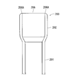
- a pipe 200 connected to a hermetic container (not shown) is composed of a raw pipe part 201 on the side of the hermetic container and a pipe expansion part 202 expanded from the pipe part 201, and a tip side part (tip part) of the pipe expansion part 202.
- 203 is crushed and brazed as described above. In this state, an airtight test is performed by applying high pressure to the sealed container.
- the base portion of the distal end portion 203 of the pipe 200 is formed with a cut portion 204 for later folding. After the airtight test, the distal end portion 203 brazed at the cut portion 204 is folded, as shown in FIG. The leading end opening 206 was formed.
- the conventional sealing plug 207 is made of rubber such as chloroprene rubber, and includes a flange portion 208 as shown in FIG. 10 and an insertion portion 209 protruding from the flange portion 208. Further, a bottomed hole 211 is formed in the center of the flange portion 208 so as to be drilled toward the insertion portion 209. Then, an insertion jig is inserted into the hole 211, and the insertion portion 209 of the sealing plug 207 is inserted into the expanded portion 202 of the pipe 200 from the tip opening 206 of the pipe 200 and is brought into close contact with the inner surface thereof. Thereafter, a screw (not shown) is screwed into the hole 211 so that the insertion portion 209 is pressed against the inner surface of the expanded tube portion 202 to seal the distal end opening 206.
- a screw (not shown) is screwed into the hole 211 so that the insertion portion 209 is pressed against the inner surface of the expanded tube portion 202 to seal the distal
- the edge portion 206A of the tip opening 206 is extremely sharp (sharp edge).
- the outer diameter of the insertion portion 209 of the sealing plug 207 is set to be larger than the inner diameter of the tube expansion portion 202 so as to be in close contact with the inner surface of the tube expansion portion 202. Therefore, when the insertion portion 209 of the sealing plug 207 is inserted into the sealing plug 207 from the distal end opening 206, the outer surface of the insertion portion 209 is scraped and damaged by the sharp edge portion 206A of the distal opening 206. There has been a problem that a bag (rubber bag) enters the sealed container from the pipe 200 and causes the compression element to be locked.
- the present invention has been made to solve the conventional technical problems, and can avoid inconveniences caused by damage to the sealing plug at the opening of the end of the pipe connected to the sealed container.
- a compressor that can be used and a sealing plug for the compressor are provided.
- the compressor according to the first aspect of the present invention is such that a sealing plug is attached to a front end opening of a pipe connected to the hermetic container, and the pipe is connected to the raw tube portion on the hermetic container side.
- the expansion tube is expanded from the raw tube portion and located on the tip opening side, and the sealing plug has a flange portion and an insertion portion that protrudes from the flange portion and is inserted into the pipe.
- the insertion part has a stepped shape composed of a large diameter part on the flange side and a small diameter part on the tip side, and the outer diameter of the small diameter part is smaller than the inner diameter of the expanded pipe part of the pipe and larger than the inner diameter of the raw pipe part. It is said that it is said.
- the small diameter portion of the sealing plug is the raw pipe of the piping before the large diameter portion of the sealing plug reaches the tip opening of the pipe. It reaches the part.
- the small diameter portion and the large diameter portion of the sealing plug in each of the above-mentioned inventions respectively enter into the raw pipe portion and the expanded pipe portion of the pipe so as to be in close contact with the inner surface thereof, and the large size of the sealing plug.
- the dimensional difference between the outer diameter of the diameter part and the inner diameter of the expanded pipe part of the pipe is smaller than the dimensional difference between the outer diameter of the small diameter part of the sealing plug and the inner diameter of the raw pipe part of the pipe.
- a compressor having a bottomed hole formed in an axial center portion of the sealing plug in each of the above inventions, and a screw inserted into the bottomed hole and screwed therein.
- the groove is formed only on the head side of the screw.
- a sealing plug for a compressor according to a fifth aspect of the present invention is connected to a hermetic container of the compressor, and has an elementary pipe part on the side of the hermetic container and an enlarged pipe part that is expanded from the elementary pipe part and located on the distal end opening side.
- the flange has a flange portion and an insertion portion that protrudes from the flange portion and is inserted into the piping.
- the insertion portion is a large-diameter portion on the flange side. It has a step shape composed of a small-diameter portion on the distal end side, and the outer diameter of the small-diameter portion is smaller than the inner diameter of the expanded portion of the pipe and larger than the inner diameter of the raw tube portion.
- the small diameter part reaches the raw pipe part of the pipe before the large diameter part reaches the tip opening of the pipe. It is characterized by.
- the compressor sealing plug according to the fifth or sixth aspect, wherein the small-diameter portion and the large-diameter portion respectively enter the raw pipe portion and the expanded pipe portion of the pipe and adhere to the inner surfaces thereof.
- the dimensional difference between the outer diameter of the large diameter portion and the inner diameter of the expanded pipe portion of the pipe is smaller than the dimensional difference between the outer diameter of the small diameter portion and the inner diameter of the raw pipe portion of the pipe.
- a compressor sealing plug according to any one of the fifth to seventh aspects, wherein the bottomed hole formed in the shaft center portion is inserted into the bottomed hole and screwed. And a screw groove of the screw is formed only on the head side of the screw.
- a sealing stopper has a collar part and the insertion part which protrudes from this collar part and is inserted in piping,
- This insertion part is large on the collar part side. It has a stepped shape consisting of a diameter part and a small diameter part on the tip side, and the outer diameter of this small diameter part is smaller than the inner diameter of the expanded pipe part of the pipe and larger than the inner diameter of the raw pipe part.
- the small diameter portion is the raw pipe of the pipe before the large diameter portion reaches the tip opening of the pipe. So that the sealing plug can be inserted into the raw tube portion first from the small diameter portion on the tip side, and the large diameter portion on the heel portion first reaches the tip opening, Insertability can be improved as compared with the case where the small diameter portion and the large diameter portion simultaneously reach the raw tube portion and the tip opening, respectively.
- the small diameter part and the large diameter part of the sealing plug respectively enter the raw pipe part and the pipe expansion part of the pipe so as to be in close contact with the inner surface thereof.
- the sealing performance of the piping is improved.
- the dimensional difference between the outer diameter of the large diameter portion and the inner diameter of the expanded pipe portion of the pipe is smaller than the dimensional difference between the outer diameter of the small diameter portion and the inner diameter of the raw pipe portion of the pipe.
- the sealing plug includes a bottomed hole formed in the shaft center portion, and a screw inserted into the bottomed hole and screwed therein. Since the thread groove of this screw is formed only on the head side of the screw, the screwing operation for pressing the sealing plug against the inner surface of the pipe is facilitated.
- FIG. 1 shows a longitudinal side view of an internal intermediate pressure type multi-stage (two-stage) compressor 10 including first and second rotary compression elements 32 and 34 as an embodiment to which the present invention is applied.
- reference numeral 10 denotes an internal intermediate pressure type multistage compression compressor (rotary compressor) using, for example, carbon dioxide (CO 2 ) as a refrigerant.
- the compressor 10 includes a cylindrical sealed container 12 made of a steel plate, The electric element 14 disposed and housed above the internal space of the sealed container 12 and the first rotary compression element 32 (first stage) disposed below the electric element 14 and driven by the rotating shaft 16 of the electric element 14. ) And a second rotary compression element 34 (second stage).
- a terminal (wiring is omitted) 20 for supplying electric power to the electric element 14 is attached to the end cap (lid) 12C of the sealed container 12.
- the electric element 14 includes a stator 22 attached in an annular shape along the inner peripheral surface of the upper space of the hermetic container 12, and a rotor 24 inserted and arranged with a slight gap inside the stator 22.
- the rotor 24 is fixed to a rotating shaft 16 that passes through the center and extends in the vertical direction.
- the stator 22 has a laminated body 26 in which donut-shaped electromagnetic steel plates are laminated, and a stator coil 28 wound around the laminated body 26.
- the rotor 24 is also formed by a laminated body 30 of electromagnetic steel sheets, and a permanent magnet is inserted into the laminated body 30.
- the first rotary compression element 32 and the second rotary compression element 34 include a cylinder 38 and a cylinder 40 arranged above and below, and a rotary shaft 16 having a phase difference of 180 degrees in the upper and lower cylinders 38 and 40.
- the upper and lower rollers 46, 48 fitted to the upper and lower eccentric portions 42, 44 and rotated eccentrically, and the upper and lower cylinders 38, 40 in contact with the upper and lower rollers 46, 48 are respectively connected to the low pressure chamber side and the high pressure chamber side.
- the upper and lower vanes 50 (the lower vanes are not shown) and the upper support member that also serves as a bearing for the rotary shaft 16 by closing the upper opening surface of the upper cylinder 38 and the lower opening surface of the lower cylinder 40.
- 54 and a lower support member 56 The upper support member 54 and the lower support member 56 have a discharge silencer chamber, and the openings of the discharge silencer chamber are closed by covers 66 and 68, respectively.
- a spring 76 is accommodated in the above-described guide groove for accommodating the vane 50.
- the spring 76 abuts on the outer end of the vane 50 and constantly urges the vane 50 toward the roller 46.
- a metal plug 137 is provided on the airtight container 12 side of the spring 76 and serves to prevent the spring 76 from coming off.
- the carbon dioxide (CO 2 ) as an example of carbon dioxide gas which is a natural refrigerant in consideration of flammability and toxicity, is used as the refrigerant
- the oil as the lubricating oil is, for example, Existing oils such as mineral oil (mineral oil), alkylbenzene oil, ether oil and ester oil are used.
- a refrigerant introduction pipe (pipe) 92 for introducing refrigerant gas to the upper cylinder 38 is connected to the side surface of the sealed container 12, and one end of the refrigerant introduction pipe 92 communicates with the upper cylinder 38.
- the refrigerant introduction pipe 92 passes through the upper side of the sealed container 12, and the other end communicates with the sealed container 12.
- a refrigerant introduction pipe (pipe) 94 for introducing refrigerant gas to the lower cylinder 40 is connected to the sealed container 12, and one end of the refrigerant introduction pipe 94 is communicated with the lower cylinder 40.
- a refrigerant discharge pipe (pipe) 96 is connected to the sealed container 12, and one end of the refrigerant discharge pipe 96 is communicated with the discharge silencer chamber of the second rotary compression element 34.
- the low-pressure (first-stage suction pressure LP: 4 MPaG) refrigerant gas sucked from the refrigerant introduction pipe 94 to the low-pressure chamber side of the lower cylinder 40 is compressed by the operation of the roller 48 and the vane, and the intermediate pressure (MP1: 8 MPaG).
- MP1 intermediate pressure
- the intermediate-pressure refrigerant gas in the sealed container 12 is sucked into the low-pressure chamber side of the upper cylinder 38 via the refrigerant introduction pipe 92 (second-stage suction pressure MP2).
- the suctioned intermediate-pressure refrigerant gas is compressed in the second stage by the operation of the roller 46 and the vane 50 to become a high-temperature and high-pressure refrigerant gas (second-stage discharge pressure HP: 12 MPaG), and is supported upward from the high-pressure chamber side. It is discharged to the outside via the discharge silencer chamber formed in the member 54 and the refrigerant discharge pipe 96.
- the inside of the sealed container 12 is at a very high pressure such as 8 MPaG. Therefore, an extremely high pressure is applied to the sealed container 12 during an airtight test in the manufacturing process.
- the refrigerant introduction pipes 92 and 94 and the refrigerant discharge pipe 96 (both pipes in the present application) connected to the sealed container 12 are crushed in the same manner as the pipe 200 in FIGS.
- An airtight test is performed in the brazed state. After the test, the tip opening is formed by folding.
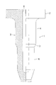
- FIG. 2 shows a vertical side view of the tip of the refrigerant discharge pipe 96 of the compressor 10
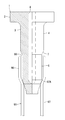
- FIG. 3 shows a partial vertical side view of the sealing plug 1 of the present invention.
- the refrigerant introduction pipe (pipe) 96 includes a raw pipe part 97 having an original pipe diameter and a pipe expansion part 98 in which the distal end side of the raw pipe part 97 is expanded. Is connected to the hermetic container 12, and the expanded pipe portion 98 is located closer to the distal end opening 99 than the raw tube portion 97.
- a portion of the raw pipe portion 97 that is continuous with the pipe expanding portion 98 is a continuous portion 97A that is inclined obliquely outward.
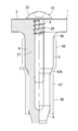
- the sealing plug 1 of the present invention is made of rubber such as chloroprene rubber, and includes a wide flange portion 2 having a circular shape in plan view, and an insertion portion 3 protruding from the flange portion 2.
- the insertion portion 3 includes a cylindrical large-diameter portion 4 positioned on the flange portion 2 side, and a cylindrical small-diameter portion 6 positioned closer to the distal end side than the large-diameter portion 4 and thinner than the large-diameter portion 4. It has a stepped shape, and the tip of the small diameter portion 6 is tapered like a bowl. Moreover, the small diameter part 6 of the part which continues to the large diameter part 4 is made into the continuous part 7 which expanded the diameter diagonally outside.
- a bottomed hole 8 extending to the small diameter portion 6 is formed in the center of the flange portion 2 of the sealing plug 1 so as to insert a jig used for inserting the sealing plug 1 into the refrigerant discharge pipe 96. .
- the outer diameter of the small diameter portion 6 of the sealing plug 1 is set to be smaller than the inner diameter of the expanded portion 98 of the refrigerant discharge pipe 96 and larger than the inner diameter of the base tube portion 97.
- the outer diameter of the large diameter portion 4 is set to be larger than the inner diameter of the expanded portion 98 of the refrigerant discharge pipe 96, but the outer diameter of the large diameter portion 4 and the inner diameter of the expanded portion 98 of the sealing plug 1 are The dimensional difference is set smaller than the dimensional difference between the outer diameter of the small-diameter portion 6 and the inner diameter of the raw tube portion 97, and even if the large-diameter portion 4 hits the tip opening 99, it is not damaged and wrinkles are not generated.
- the dimensions are of the order (indicated by broken lines in FIG. 7).
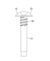
- the screw 13 inserted into the hole 8 after the sealing plug 1 is inserted includes a head portion 23 and a screw portion 27 protruding from the head portion 23 as shown in FIG.
- the groove 29 is formed, in this case, the screw groove 29 is formed only on the head portion 23 side of the screw portion 27, and in the embodiment, the size thereof is set to 1 ⁇ 2 or less of the total length of the screw portion 27. Yes.
- the inner diameter and depth of the hole 8 are common to the sealing plugs 1 corresponding to the refrigerant discharge pipes 96 having different diameters. Thereby, it becomes possible to share the screw 13 with respect to the sealing plugs 1 having different dimensions, and the cost can be reduced.
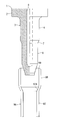
- an insertion jig (not shown) is inserted into the hole 8, and the sealing plug 1 is inserted from the small diameter portion 6 at the distal end of the insertion portion 3 of the sealing plug 1 to the distal end opening 99 of the refrigerant discharge pipe 96 as shown in FIG. Insert it.
- the outer diameter of the small-diameter portion 6 of the sealing plug 1 is smaller than the inner diameter of the expanded portion 98 of the refrigerant discharge tube 96, so that it does not hit against the edge of the tip opening 99 of the refrigerant discharge tube 96 and is not pressed.
- the sealing plug 1 when the sealing plug 1 is further inserted, before the continuous portion 7 and the large diameter portion 4 of the sealing plug 1 reach the tip opening 99 of the refrigerant discharge pipe 96, the small diameter portion 6 as shown in FIG. The tip reaches the continuous portion 97A of the raw tube portion 97 of the refrigerant discharge tube 96 and comes into contact therewith. Thus, the length dimension of the large diameter part 4 and the small diameter part 6 is set. Therefore, at this time, the refrigerant discharge pipe 96 is closed, and thereafter foreign matter is prevented from entering the sealed container 12.
- the continuous portion 7 of the sealing plug 1 eventually hits the continuous portion 97A of the base pipe portion 97 of the refrigerant discharge pipe 96 and can no longer be inserted (FIG. 7). .
- the small diameter portion 6 is formed before the large diameter portion 4 reaches the tip opening 99 of the refrigerant discharge pipe 96.
- the insertion portion 3 of the sealing plug 1 can be inserted into the raw tube portion 97 first from the small-diameter portion 6 on the distal end side, the insertion portion 3 of the sealing plug 1 can be inserted into the large portion on the flange portion 2 side.
- the insertability is better than when the diameter portion 4 reaches the tip opening 99 first, or when the small diameter portion 6 and the large diameter portion 4 simultaneously reach the continuous portion 97A and the tip opening 99, respectively.
- the outer diameters of the small-diameter portion 6 and the large-diameter portion 4 of the sealing plug 1 are set larger than the inner diameters of the raw tube portion 97 and the expanded tube portion 98 of the refrigerant discharge tube 96, respectively.
- the small diameter portion 6 and the large diameter portion 4 are press-fitted into the raw tube portion 97 and the expanded tube portion 98 of the refrigerant discharge tube 96, respectively, and the outer surfaces of the small diameter portion 6 and the large diameter portion 4 are the raw tube portion 97 and the expanded tube portion 98, respectively. Adheres closely to the inner surface. Thereby, the sealing performance of the refrigerant
- the dimensional difference between the outer diameter of the large-diameter portion 4 of the sealing plug 1 and the inner diameter of the expanded portion 98 of the refrigerant discharge pipe 96 is the same as the outer diameter of the small-diameter portion 6 and the inner diameter of the base tube portion 97 of the refrigerant discharge pipe 96. Therefore, the base tube portion 97 of the refrigerant discharge tube 96 can be reliably sealed by the small diameter portion 6.
- the dimensional difference between the outer diameter of the large diameter portion 4 and the inner diameter of the expanded tube portion 98 is smaller than the dimensional difference between the outer diameter of the small diameter portion 6 and the inner diameter of the raw tube portion 97. Resistance is reduced and insertion is further improved.
- the sealing plug 1 is attached to the tip opening 99 of the refrigerant discharge pipe 96.
- the adhesion to the inner surface of the refrigerant discharge pipe 96 is further improved, and the sealing plug 1 includes the large diameter portion 4 and the small diameter portion 6.
- the expanded tube portion 98 and the raw tube portion 97 are pressed against each other. Further, the penetration of moisture from the holes 8 is also avoided.
- the screw groove 29 of the screw 13 is formed only on the head 23 side, the screwing operation of the screw 13 is also facilitated.
- the sealing plug 1 of the compressor 10 of the present invention includes the flange portion 2, the insertion portion 3 that protrudes from the flange portion 2 and is inserted into the refrigerant discharge pipe 96 and the refrigerant introduction pipes 92 and 94.
- the insertion portion 3 has a stepped shape including a large-diameter portion 4 on the flange portion 2 side and a small-diameter portion 6 on the distal end side, and the outer diameter of the small-diameter portion 6 is an expanded pipe such as the refrigerant discharge pipe 96.
- the size is smaller than the inner diameter of the portion 98 and larger than the inner diameter of the raw tube portion 97, when the small-diameter portion 6 of the sealing plug 1 is inserted from the tip opening 99 of the refrigerant discharge tube 96 or the like, It is possible to prevent damage at the edge. As a result, it is possible to avoid the inconvenience that the sealing plug 1 is damaged at the tip opening 99 and the generated wrinkles enter the compressor 10 to deteriorate the quality.
- the small diameter portion 6 is in close contact with the inner surface of the raw tube portion 97, the refrigerant discharge tube 96 and the like can be sealed without any trouble.
- the sealing plug 1 when the sealing plug 1 is inserted into the refrigerant discharge pipe 96 or the like, the small diameter portion 6 reaches the continuous portion 97A of the raw tube portion 97 before the large diameter portion 4 reaches the tip opening 99. Therefore, the sealing plug 1 can be inserted into the raw tube portion 97 first from the small-diameter portion 6 on the distal end side, and the large-diameter portion 4 on the flange portion 2 side reaches the distal end opening 99 first. As compared with the case where the small-diameter portion 6 and the large-diameter portion 4 reach the raw tube portion 97 and the tip opening 99 at the same time, the insertability can be improved.
- the small diameter portion 6 and the large diameter portion 4 of the sealing plug 1 enter the base tube portion 97 and the expanded tube portion 98 of the refrigerant discharge pipe 96 or the like and come into close contact with the inner surfaces thereof, the refrigerant discharge pipe 96 or the like Sealing performance is improved. Further, since the dimensional difference between the outer diameter of the large diameter portion 4 and the inner diameter of the expanded pipe portion 98 is made smaller than the dimensional difference between the outer diameter of the small diameter portion 6 and the inner diameter of the raw tube portion 97, the small diameter portion 6 While securely sealing the tube portion 97, the resistance when the sealing plug 1 is inserted can be reduced, and the insertion property can be further improved.
- the present invention is applied to the compressor 10 that uses carbon dioxide as a refrigerant.
- the present invention is not limited thereto and is effective for various compressors.
Landscapes
- Engineering & Computer Science (AREA)
- Mechanical Engineering (AREA)
- General Engineering & Computer Science (AREA)
- Compressor (AREA)
- Applications Or Details Of Rotary Compressors (AREA)
Abstract
密閉容器に接続された配管の先端開口で密封栓が損傷することによって発生する不都合を未然に回避することができる圧縮機を提供する。圧縮機は、密閉容器に接続された冷媒吐出管96の先端開口99に密封栓1を装着する。冷媒導入管は、密閉容器側の素管部97と、素管部より拡管されて先端開口側に位置する拡管部98とを有し、密封栓は、鍔部2と、鍔部から突出して冷媒吐出管内に挿入される挿入部3とを有し、挿入部は、鍔部側の大径部4と先端側の小径部6とから成る段差形状を呈し、小径部の外径は、拡管部の内径より小さく、素管部の内径より大きい寸法とされている。
Description
本発明は、密閉容器に接続された配管の先端開口に密封栓を装着した圧縮機及び当該圧縮機用密封栓に関するものである。
従来より冷凍サイクル装置で使用される圧縮機は、密閉容器内に電動要素や圧縮要素を備えると共に、密閉容器には冷媒吐出管や冷媒導入管等の各種配管が接続されている。また、二酸化炭素等の冷媒を圧縮する圧縮機では、密閉容器内部が高圧になるため、製造工程における気密試験時にも高い圧力が密閉容器内に加えられる。この場合、密閉容器に接続された各配管は先端を潰し、ロウ付けした状態で気密試験を行い、試験後に折り欠いて先端開口を形成する。そして、この先端開口には、ゴム製の密封栓を挿入して密封していた(例えば、特許文献1参照)。
ここで、図8乃至図10を参照しながら、従来の係る密封栓を用いた構造について説明する。図8は上記気密試験時における配管先端部の構造を示している。図示しない密閉容器に接続された配管200は、密閉容器側の素管部201と、この素管部201より拡管された拡管部202から成り、この拡管部202の先端側の部分(先端部)203が上述のように潰され、ロウ付けされている。この状態で密閉容器内に高圧を加えて気密試験を行う。
また、配管200の先端部203の基部には後に折り欠くための切れ目部204が形成されており、気密試験後にこの切れ目部204にてロウ付けされた先端部203を折り欠き、図9のような先端開口206を形成していた。
一方、従来の密封栓207はクロロプレンゴム等のゴム製であり、図10に示されるような鍔部208と、この鍔部208から突出した挿入部209とを備えていた。更に、鍔部208の中央には挿入部209に向けて穿たれた有底の孔211が形成されている。そして、挿入用の治具をこの孔211に差し込み、密封栓207の挿入部209を配管200の先端開口206から配管200の拡管部202内に挿入してその内面に密着させる。その後、孔211に図示しないネジを螺合させて挿入部209を拡管部202の内面に圧接させることで、先端開口206を密封していた。
しかしながら、上述したように配管200は気密試験後に切れ目部204にて先端部203を折り欠いて取り除くものであるため、先端開口206の縁部206Aは極めて鋭利となる(シャープエッジ)。また、密封栓207の挿入部209の外径は、拡管部202の内面に密着させるために、拡管部202の内径よりも大きく設定されている。そのため、密封栓207を先端開口206より密封栓207の挿入部209を挿入する際、この挿入部209の外面が鋭利な先端開口206の縁部206Aで削られて傷付いてしまい、それによって生じた滓(ゴムの滓)が配管200から密閉容器内部に侵入して、圧縮要素のロック等を引き起こす問題があった。
本発明は、係る従来の技術的課題を解決するために成されたものであり、密閉容器に接続された配管の先端開口で密封栓が損傷することによって発生する不都合を未然に回避することができる圧縮機及び該圧縮機用密封栓を提供するものである。
上記課題を解決するために、請求項1の発明の圧縮機は、密閉容器に接続された配管の先端開口に密封栓を装着したものであって、配管は、密閉容器側の素管部と、この素管部より拡管されて先端開口側に位置する拡管部とを有し、密封栓は、鍔部と、この鍔部から突出して配管内に挿入される挿入部とを有し、この挿入部は、鍔部側の大径部と先端側の小径部とから成る段差形状を呈し、この小径部の外径は、配管の拡管部の内径より小さく、素管部の内径より大きい寸法とされていることを特徴とする。
請求項2の発明の圧縮機は、上記発明において密封栓を配管内に挿入したとき、密封栓の大径部が配管の先端開口に到達する以前に、密封栓の小径部が配管の素管部に到達することを特徴とする。
請求項3の発明の圧縮機は、上記各発明において密封栓の小径部と大径部は、配管の素管部と拡管部内にそれぞれ進入してそれらの内面に密着すると共に、密封栓の大径部の外径と配管の拡管部の内径との寸法差は、密封栓の小径部の外径と配管の素管部の内径との寸法差よりも小さいことを特徴とする。
請求項4の発明の圧縮機は、上記各発明において密封栓の軸心部に形成された有底孔と、この有底孔内に挿入されて螺合するネジとを備え、このネジのネジ溝は、当該ネジの頭部側のみに形成されていることを特徴とする。
請求項5の発明の圧縮機用密封栓は、圧縮機の密閉容器に接続され、この密閉容器側の素管部とこの素管部より拡管されて先端開口側に位置する拡管部とを有した配管の先端開口に装着されるものであって、鍔部と、この鍔部から突出して配管内に挿入される挿入部とを有し、この挿入部は、鍔部側の大径部と先端側の小径部とから成る段差形状を呈し、この小径部の外径は、配管の拡管部の内径より小さく、素管部の内径より大きい寸法とされていることを特徴とする。
請求項6の発明の圧縮機用密封栓は、上記発明において配管内に挿入されたとき、大径部が配管の先端開口に到達する以前に、小径部が配管の素管部に到達することを特徴とする。
請求項7の発明の圧縮機用密封栓は、請求項5又は請求項6の発明において小径部と大径部は、配管の素管部と拡管部内にそれぞれ進入してそれらの内面に密着すると共に、大径部の外径と配管の拡管部の内径との寸法差は、小径部の外径と配管の素管部の内径との寸法差よりも小さいことを特徴とする。
請求項8の発明の圧縮機用密封栓は、請求項5乃至請求項7のうちの何れかの発明において軸心部に形成された有底孔と、この有底孔内に挿入されて螺合するネジとを備え、このネジのネジ溝は、当該ネジの頭部側のみに形成されていることを特徴とする。
請求項1及び請求項5の発明によれば、密封栓が、鍔部と、この鍔部から突出して配管内に挿入される挿入部とを有し、この挿入部は、鍔部側の大径部と先端側の小径部とから成る段差形状を呈し、この小径部の外径は、配管の拡管部の内径より小さく、素管部の内径より大きい寸法とされているので、密封栓の小径部が配管の先端開口から挿入される際に、先端開口の縁部にて傷付くことを防ぐことができる。これにより、配管の先端開口にて密封栓が傷付き、発生した滓が圧縮機内部に侵入して品質が劣化する不都合を未然に回避することが可能となる。一方で、小径部は素管部の内面に密着することになるので、配管の密封も支障無く行うことができるものである。
また、請求項2及び請求項6の発明によれば、上記発明において密封栓が配管内に挿入されたとき、大径部が配管の先端開口に到達する以前に、小径部が配管の素管部に到達するようにしたので、密封栓を先端側の小径部から先に素管部内に挿入していくことができ、鍔部側の大径部が先に先端開口に到達する場合や、小径部と大径部がそれぞれ同時に素管部と先端開口に到達する場合に比して、挿入性を改善することができるようになる。
更に、請求項3及び請求項7の発明によれば、上記各発明において密封栓の小径部と大径部が、配管の素管部と拡管部内にそれぞれ進入してそれらの内面に密着するようにしたので、配管の密封性能が向上する。また、大径部の外径と配管の拡管部の内径との寸法差が、小径部の外径と配管の素管部の内径との寸法差よりも小さくなるようにしたので、小径部にて配管の素管部を確実に密封しながら、大径部の外径と拡管部の内径との寸法差は小径部の外径と素管部の内径との寸法差よりも小さくすることにより、密封栓挿入時の抵抗を低減し、挿入性を一層改善することができるようになる。
更にまた、請求項4及び請求項8の発明によれば、上記各発明において密封栓が、軸心部に形成された有底孔と、この有底孔内に挿入されて螺合するネジとを備え、このネジのネジ溝を、当該ネジの頭部側のみに形成したので、密封栓を配管内面に圧接させるためのネジの螺合作業も容易となるものである。
次に、図面に基づき本発明の実施形態を詳述する。図1は本発明を適用した実施例として、第1及び第2の回転圧縮要素32、34を備えた内部中間圧型多段(2段)圧縮式の圧縮機10の縦断側面図を示している。
各図において、10は例えば二酸化炭素(CO2)を冷媒として使用する内部中間圧型多段圧縮式の圧縮機(ロータリコンプレッサ)で、この圧縮機10は鋼板からなる円筒状の密閉容器12と、この密閉容器12の内部空間の上側に配置収納された電動要素14及びこの電動要素14の下側に配置され、電動要素14の回転軸16により駆動される第1の回転圧縮要素32(1段目)及び第2の回転圧縮要素34(2段目)からなる回転圧縮機構部18にて構成されている。
密閉容器12のエンドキャップ(蓋体)12Cには電動要素14に電力を供給するためのターミナル(配線を省略)20が取り付けられている。電動要素14は、密閉容器12の上部空間の内周面に沿って環状に取り付けられたステータ22と、このステータ22の内側に若干の間隙を設けて挿入配置されたロータ24とからなる。このロータ24は中心を通り鉛直方向に延びる回転軸16に固定されている。
ステータ22は、ドーナッツ状の電磁鋼板を積層した積層体26と、この積層体26に巻装されたステータコイル28を有している。また、ロータ24もステータ22と同様に電磁鋼板の積層体30で形成され、この積層体30内に永久磁石を挿入して構成されている。
前記第1の回転圧縮要素32と第2の回転圧縮要素34は、上下に配置されたシリンダ38、シリンダ40と、この上下シリンダ38、40内を180度の位相差を有して回転軸16に設けた上下偏心部42、44に嵌合されて偏心回転する上下ローラ46、48と、この上下ローラ46、48に当接して上下シリンダ38、40内をそれぞれ低圧室側と高圧室側に区画する上下ベーン50(下側のベーンは図示せず)と、上シリンダ38の上側の開口面及び下シリンダ40の下側の開口面を閉塞して回転軸16の軸受けを兼用する上部支持部材54及び下部支持部材56にて構成される。上部支持部材54および下部支持部材56は、吐出消音室を有しており、これら吐出消音室の開口部はそれぞれカバー66、68にて閉塞される。
また、上シリンダ38内には前述したベーン50を収納する案内溝内にスプリング76が収納され、このスプリング76はベーン50の外側端部に当接し、常時ベーン50をローラ46側に付勢する。そして、このスプリング76の密閉容器12側には金属製のプラグ137が設けられ、スプリング76の抜け止めの役目を果たす。
そして、この場合冷媒としては地球環境にやさしく、可燃性および毒性等を考慮して自然冷媒である炭酸ガスの一例としての前記二酸化炭素(CO2)を使用し、潤滑油としてのオイルは、例えば鉱物油(ミネラルオイル)、アルキルベンゼン油、エーテル油、エステル油等既存のオイルが使用される。
密閉容器12の側面には、上シリンダ38に冷媒ガスを導入するための冷媒導入管(配管)92の一端が接続され、この冷媒導入管92の一端は上シリンダ38に連通される。この冷媒導入管92は密閉容器12の上側を通過し、他端は密閉容器12内に連通する。
また、密閉容器12には下シリンダ40に冷媒ガスを導入するための冷媒導入管(配管)94の一端が接続され、この冷媒導入管94の一端は下シリンダ40に連通される。また、密閉容器12には冷媒吐出管(配管)96が接続され、この冷媒吐出管96の一端は第2の回転圧縮要素34の前記吐出消音室に連通される。
そして、ターミナル20および図示されない配線を介して電動要素14のステータコイル28に通電されると、電動要素14が起動してロータ24が回転する。この回転により回転軸16と一体に設けた上下偏心部42、44に嵌合された上下ローラ46、48が上下シリンダ38、40内を偏心回転する。
これにより、冷媒導入管94から下シリンダ40の低圧室側に吸入された低圧(一段目吸入圧LP:4MPaG)の冷媒ガスは、ローラ48とベーンの動作により圧縮されて中間圧(MP1:8MPaG)となり下シリンダ40の高圧室側より下部支持部材56に形成された吐出消音室から図示しない連通路を経て中間吐出管121から密閉容器12内に吐出される。これによって、密閉容器12内は中間圧(MP1)となる。
そして、密閉容器12内の中間圧の冷媒ガスは、冷媒導入管92を経由して上シリンダ38の低圧室側に吸入される(2段目吸入圧MP2)。吸入された中間圧の冷媒ガスは、ローラ46とベーン50の動作により2段目の圧縮が行なわれて高温高圧の冷媒ガスとなり(2段目吐出圧HP:12MPaG)、高圧室側から上部支持部材54に形成された吐出消音室、冷媒吐出管96を経由して外部に吐出されることになる。
ここで、上述の如く圧縮機10が運転されると、密閉容器12内は8MPaG等の極めて高い圧力となる。そのため、製造工程における気密試験時には極めて高い圧力が密閉容器12内に加えられる。この場合、密閉容器12に接続された冷媒導入管92、94、及び、冷媒吐出管96(何れも本願における配管)は、図8及び図9の配管200の場合と同様に先端が潰され、ロウ付けした状態で気密試験が行われる。そして、試験後に折り欠いて先端開口が形成される。
この先端開口には保管時や輸送時における異物の侵入を防止するために、密封栓1が取り付けられて密封される。以下、上記冷媒吐出管96を例にとって密封栓1の構造と取付手順について説明する。図2は圧縮機10の前記冷媒吐出管96の先端部の縦断側面図を示しており、図3は本発明の密封栓1の一部縦断側面図を示している。
冷媒導入管(配管)96は、図2に示されるように元々の配管径である素管部97と、この素管部97の先端側を拡管した拡管部98とから成り、素管部97が密閉容器12に接続され、この素管部97より先端開口99側に拡管部98が位置している。また、この拡管部98に連続する部分の素管部97は外側に斜めに傾斜した連続部97Aとされている。
一方、本発明の密封栓1は、クロロプレンゴム等のゴム製であり、平面視円形を呈する幅広の鍔部2と、この鍔部2から突出する挿入部3とから成る。この挿入部3は、鍔部2側に位置して円柱状の大径部4と、この大径部4より先端側に位置して大径部4より細い円柱状の小径部6とから成る段差形状を呈しており、この小径部6の先端は鏃状に先細りとされている。また、大径部4に連続する部分の小径部6は外側に斜めに拡径した連続部7とされている。更に、この密封栓1の鍔部2の中心には、密封栓1を冷媒吐出管96に挿入するために用いる治具を差し込むために小径部6まで至る有底の孔8が穿たれている。
この場合、密封栓1の小径部6の外径は、冷媒吐出管96の拡管部98の内径より小さく、素管部97の内径より大きい寸法に設定されている。また、大径部4の外径は、冷媒吐出管96の拡管部98の内径より大きい寸法に設定されているが、この密封栓1の大径部4の外径と拡管部98の内径との寸法差は、小径部6の外径と素管部97の内径との寸法差よりも小さく設定され、且つ、大径部4が先端開口99に当たっても傷付いて滓が発生することがない程度の寸法とされている(図7に破線で示す)。
また、密封栓1を挿入した後に孔8に差し込まれるネジ13は、図6に示すように頭部23とこの頭部23から突出するネジ部27とから成り、このネジ部27の外周にネジ溝29が形成されているが、この場合、ネジ溝29はネジ部27の頭部23側にのみ形成されており、実施例ではその寸法はネジ部27の全長の1/2以下とされている。この場合、孔8の内径及び深さは、異なる径の冷媒吐出管96に対応する密封栓1のそれぞれで共通とされている。これにより、異なる寸法の密封栓1に対してネジ13を共用することができるようになり、コストの削減を図ることが可能となる。
以上の構成で、図示しない挿入用の治具を孔8に差し込み、図4に示すように密封栓1の挿入部3先端の小径部6から冷媒吐出管96の先端開口99に密封栓1を挿入していく。このとき、密封栓1の小径部6の外径は、冷媒吐出管96の拡管部98の内径よりも小さいので、冷媒吐出管96の先端開口99の縁部に当たり、押し付けられることがない。そして、更に密封栓1を挿入していくと、密封栓1の連続部7及び大径部4が冷媒吐出管96の先端開口99に到達する以前に、図5に示すように小径部6の先端が冷媒吐出管96の素管部97の連続部97Aに到達し、当接する。そのように大径部4と小径部6の長さ寸法を設定しておく。従って、この時点で冷媒吐出管96は塞がれ、以後密閉容器12内への異物の侵入は阻止される。
そして、更に密封栓1を冷媒吐出管96内に挿入していくと、やがて密封栓1の連続部7が冷媒吐出管96の素管部97の連続部97Aに当たってそれ以上差し込めなくなる(図7)。このように、密封栓1の挿入部3を冷媒吐出管96内に挿入していくときに、大径部4が冷媒吐出管96の先端開口99に到達する以前に、小径部6が素管部97に到達するようにしたので、密封栓1の挿入部3を先端側の小径部6から先に素管部97内に挿入していくことができるようになり、鍔部2側の大径部4が先に先端開口99に到達する場合や、小径部6と大径部4がそれぞれ同時に連続部97Aと先端開口99に到達する場合に比べて、挿入性が良好となる。また、このとき、密封栓1の小径部6及び大径部4の外径は、それぞれ冷媒吐出管96の素管部97及び拡管部98の内径よりも大きく設定されているので、密封栓1の小径部6及び大径部4は、それぞれ冷媒吐出管96の素管部97及び拡管部98内に圧入され、小径部6及び大径部4の外面は、素管部97及び拡管部98の内面に密着する。これにより、従来の密封栓よりも冷媒吐出管96の密封性が向上する。
このとき、密封栓1の大径部4の外径と冷媒吐出管96の拡管部98の内径との寸法差は、小径部6の外径と冷媒吐出管96の素管部97の内径との寸法差よりも小さく設定されているので、小径部6にて冷媒吐出管96の素管部97を確実に密封することができる。一方、大径部4の外径と拡管部98の内径との寸法差が小径部6の外径と素管部97の内径との寸法差よりも小さいので、密封栓1を挿入する時の抵抗が低減され、挿入性が一層改善される。
その後、治具を抜いて代わりにネジ13を孔8に差し込み、螺合させる。このようにして密封栓1は冷媒吐出管96の先端開口99に装着される。また、ネジ13が螺合することで密封栓1の挿入部3全体が拡幅されるので、冷媒吐出管96内面への密着性は更に向上し、密封栓1は大径部4と小径部6の全体で拡管部98と素管部97に圧接する。また、孔8からの水分の浸透も回避される。このとき、ネジ13のネジ溝29は、頭部23側のみに形成されているので、ネジ13の螺合作業も容易となる。
以上詳述したように、本発明の圧縮機10の密封栓1は鍔部2と、この鍔部2から突出して冷媒吐出管96や冷媒導入管92、94内に挿入される挿入部3とを有し、この挿入部3は、鍔部2側の大径部4と先端側の小径部6とから成る段差形状を呈し、この小径部6の外径は、冷媒吐出管96等の拡管部98の内径より小さく、素管部97の内径より大きい寸法とされているので、密封栓1の小径部6が冷媒吐出管96等の先端開口99から挿入される際に、先端開口99の縁部にて傷付くことを防ぐことができる。これにより、先端開口99にて密封栓1が傷付き、発生した滓が圧縮機10内部に侵入して品質が劣化する不都合を未然に回避することが可能となる。一方で、小径部6は素管部97の内面に密着することになるので、冷媒吐出管96等の密封も支障無く行うことができるものである。
また、密封栓1が冷媒吐出管96等の内部に挿入されたとき、大径部4が先端開口99に到達する以前に、小径部6が素管部97の連続部97Aに到達するようにしたので、密封栓1を先端側の小径部6から先に素管部97内に挿入していくことができ、鍔部2側の大径部4が先に先端開口99に到達する場合や、小径部6と大径部4がそれぞれ同時に素管部97と先端開口99に到達する場合に比して、挿入性を改善することができるようになる。
更に、密封栓1の小径部6と大径部4は、冷媒吐出管96等の素管部97と拡管部98内にそれぞれ進入してそれらの内面に密着するので、冷媒吐出管96等の密封性能が向上する。また、大径部4の外径と拡管部98の内径との寸法差が、小径部6の外径と素管部97の内径との寸法差よりも小さくなるようにしたので、小径部6にて素管部97を確実に密封しながら、密封栓1挿入時の抵抗を低減し、挿入性を一層改善することができるようになる。
更にまた、密封栓1の孔8内に挿入されて螺合するネジ13のネジ溝29を、当該ネジ13の頭部23側のみに形成したので、密封栓1を冷媒吐出管96内面に圧接させるためのネジ13の螺合作業も容易となる。
尚、実施例では冷媒として二酸化炭素を使用する圧縮機10に本発明を適用したが、それに限らず、種々の圧縮機に有効であることは云うまでもない。
1 密封栓
2 鍔部
3 挿入部
4 大径部
6 小径部
8 孔
10 圧縮機
12 密閉容器
13 ネジ
92、94 冷媒導入管
96 冷媒吐出管
2 鍔部
3 挿入部
4 大径部
6 小径部
8 孔
10 圧縮機
12 密閉容器
13 ネジ
92、94 冷媒導入管
96 冷媒吐出管
Claims (8)
- 密閉容器に接続された配管の先端開口に密封栓を装着した圧縮機において、
前記配管は、前記密閉容器側の素管部と、該素管部より拡管されて前記先端開口側に位置する拡管部とを有し、
前記密封栓は、鍔部と、該鍔部から突出して前記配管内に挿入される挿入部とを有し、該挿入部は、前記鍔部側の大径部と先端側の小径部とから成る段差形状を呈し、該小径部の外径は、前記配管の拡管部の内径より小さく、素管部の内径より大きい寸法とされていることを特徴とする圧縮機。 - 前記密封栓を前記配管内に挿入したとき、前記密封栓の大径部が前記配管の先端開口に到達する以前に、前記密封栓の小径部が前記配管の素管部に到達することを特徴とする請求項1に記載の圧縮機。
- 前記密封栓の小径部と大径部は、前記配管の素管部と拡管部内にそれぞれ進入してそれらの内面に密着すると共に、前記密封栓の大径部の外径と前記配管の拡管部の内径との寸法差は、前記密封栓の小径部の外径と前記配管の素管部の内径との寸法差よりも小さいことを特徴とする請求項1又は請求項2に記載の圧縮機。
- 前記密封栓の軸心部に形成された有底孔と、該有底孔内に挿入されて螺合するネジとを備え、
該ネジのネジ溝は、当該ネジの頭部側のみに形成されていることを特徴とする請求項1乃至請求項3のうちの何れかに記載の圧縮機。 - 圧縮機の密閉容器に接続され、該密閉容器側の素管部と該素管部より拡管されて先端開口側に位置する拡管部とを有した配管の前記先端開口に装着される密封栓において、
鍔部と、該鍔部から突出して前記配管内に挿入される挿入部とを有し、該挿入部は、前記鍔部側の大径部と先端側の小径部とから成る段差形状を呈し、該小径部の外径は、前記配管の拡管部の内径より小さく、素管部の内径より大きい寸法とされていることを特徴とする圧縮機用密封栓。 - 前記配管内に挿入されたとき、前記大径部が前記配管の先端開口に到達する以前に、前記小径部が前記配管の素管部に到達することを特徴とする請求項5に記載の圧縮機用密封栓。
- 前記小径部と大径部は、前記配管の素管部と拡管部内にそれぞれ進入してそれらの内面に密着すると共に、前記大径部の外径と前記配管の拡管部の内径との寸法差は、前記小径部の外径と前記配管の素管部の内径との寸法差よりも小さいことを特徴とする請求項5又は請求項6に記載の圧縮機用密封栓。
- 軸心部に形成された有底孔と、該有底孔内に挿入されて螺合するネジとを備え、
該ネジのネジ溝は、当該ネジの頭部側のみに形成されていることを特徴とする請求項5乃至請求項7のうちの何れかに記載の圧縮機用密封栓。
Priority Applications (1)
| Application Number | Priority Date | Filing Date | Title |
|---|---|---|---|
| CN201180074681.0A CN103917782B (zh) | 2011-11-11 | 2011-11-25 | 压缩机及压缩机用密封栓 |
Applications Claiming Priority (2)
| Application Number | Priority Date | Filing Date | Title |
|---|---|---|---|
| JP2011247277A JP5935036B2 (ja) | 2011-11-11 | 2011-11-11 | 圧縮機及び圧縮機用密封栓 |
| JP2011-247277 | 2011-11-11 |
Publications (1)
| Publication Number | Publication Date |
|---|---|
| WO2013069072A1 true WO2013069072A1 (ja) | 2013-05-16 |
Family
ID=48288661
Family Applications (1)
| Application Number | Title | Priority Date | Filing Date |
|---|---|---|---|
| PCT/JP2011/006558 Ceased WO2013069072A1 (ja) | 2011-11-11 | 2011-11-25 | 圧縮機及び圧縮機用密封栓 |
Country Status (3)
| Country | Link |
|---|---|
| JP (1) | JP5935036B2 (ja) |
| CN (1) | CN103917782B (ja) |
| WO (1) | WO2013069072A1 (ja) |
Families Citing this family (3)
| Publication number | Priority date | Publication date | Assignee | Title |
|---|---|---|---|---|
| EP2998769A4 (en) | 2013-05-16 | 2016-12-21 | Nippon Kayaku Kk | INFRARED SHIELDING FOIL, METHOD FOR THE PRODUCTION THEREOF AND APPLICATION THEREOF |
| CN105673446B (zh) * | 2016-03-18 | 2018-01-23 | 安徽美芝制冷设备有限公司 | 压缩机以及压缩机用柔性密封塞 |
| CN112153877A (zh) * | 2020-10-21 | 2020-12-29 | 珠海格力电器股份有限公司 | 降温装置及空调系统 |
Citations (2)
| Publication number | Priority date | Publication date | Assignee | Title |
|---|---|---|---|---|
| JPH09151874A (ja) * | 1995-11-29 | 1997-06-10 | Sanyo Electric Co Ltd | 冷媒圧縮機 |
| JP3063200U (ja) * | 1999-04-20 | 1999-10-19 | 船井電機株式会社 | 圧縮機 |
Family Cites Families (3)
| Publication number | Priority date | Publication date | Assignee | Title |
|---|---|---|---|---|
| US4502511A (en) * | 1983-01-03 | 1985-03-05 | Westinghouse Electric Corp. | Tube plug |
| FR2599791B1 (fr) * | 1986-06-04 | 1988-10-28 | Framatome Sa | Procede de fixation resistante et etanche d'un element cylindrique creux a l'interieur d'un tube et element cylindrique pour la mise en oeuvre de ce procede |
| JPH0363200U (ja) * | 1989-10-24 | 1991-06-20 |
-
2011
- 2011-11-11 JP JP2011247277A patent/JP5935036B2/ja active Active
- 2011-11-25 CN CN201180074681.0A patent/CN103917782B/zh active Active
- 2011-11-25 WO PCT/JP2011/006558 patent/WO2013069072A1/ja not_active Ceased
Patent Citations (2)
| Publication number | Priority date | Publication date | Assignee | Title |
|---|---|---|---|---|
| JPH09151874A (ja) * | 1995-11-29 | 1997-06-10 | Sanyo Electric Co Ltd | 冷媒圧縮機 |
| JP3063200U (ja) * | 1999-04-20 | 1999-10-19 | 船井電機株式会社 | 圧縮機 |
Also Published As
| Publication number | Publication date |
|---|---|
| CN103917782A (zh) | 2014-07-09 |
| JP2013104324A (ja) | 2013-05-30 |
| CN103917782B (zh) | 2016-01-06 |
| JP5935036B2 (ja) | 2016-06-15 |
Similar Documents
| Publication | Publication Date | Title |
|---|---|---|
| CN100376799C (zh) | 压缩机 | |
| AU2013201311A1 (en) | Rotary compressor | |
| JP5935036B2 (ja) | 圧縮機及び圧縮機用密封栓 | |
| JP4583211B2 (ja) | 密閉形圧縮機及びこれを用いた冷凍サイクル装置 | |
| KR20070049969A (ko) | 로터리 압축기 | |
| JP2003254276A (ja) | ロータリコンプレッサ | |
| EP3141754B1 (en) | Rotary compressor and method for manufacturing the same | |
| JP2003176796A (ja) | 回転式圧縮機 | |
| KR20070073314A (ko) | 로터리 압축기 | |
| JP5660151B2 (ja) | スクロール圧縮機 | |
| JP2008163874A (ja) | ロータリー圧縮機 | |
| JP2014145261A (ja) | 吐出マフラー構造およびロータリー圧縮機 | |
| JP2005220752A (ja) | 圧縮機 | |
| JP4695045B2 (ja) | 内部中間圧2段圧縮機 | |
| JP2005054652A (ja) | 密閉型圧縮機 | |
| JP2003254272A (ja) | ロータリコンプレッサ | |
| JP2005105962A (ja) | コンプレッサ | |
| JP2009013870A (ja) | 密閉型圧縮機 | |
| JP2012087665A (ja) | ロータリー圧縮機 | |
| JP2003106276A (ja) | 2段圧縮式ロータリコンプレッサ | |
| JP4371758B2 (ja) | 圧縮機 | |
| JP2005248754A (ja) | 圧縮機 | |
| JP2006274836A (ja) | 上カップマフラーの取付け方法 | |
| JP2007170409A (ja) | ロータリコンプレッサ | |
| JP4401365B2 (ja) | ロータリコンプレッサ |
Legal Events
| Date | Code | Title | Description |
|---|---|---|---|
| 121 | Ep: the epo has been informed by wipo that ep was designated in this application |
Ref document number: 11875465 Country of ref document: EP Kind code of ref document: A1 |
|
| NENP | Non-entry into the national phase |
Ref country code: DE |
|
| 122 | Ep: pct application non-entry in european phase |
Ref document number: 11875465 Country of ref document: EP Kind code of ref document: A1 |