WO2013061930A1 - 情報記録媒体、情報記録再生装置、情報記録再生方法、情報記録再生プログラム、およびコンピュータ読み取り可能な記録媒体 - Google Patents
情報記録媒体、情報記録再生装置、情報記録再生方法、情報記録再生プログラム、およびコンピュータ読み取り可能な記録媒体 Download PDFInfo
- Publication number
- WO2013061930A1 WO2013061930A1 PCT/JP2012/077249 JP2012077249W WO2013061930A1 WO 2013061930 A1 WO2013061930 A1 WO 2013061930A1 JP 2012077249 W JP2012077249 W JP 2012077249W WO 2013061930 A1 WO2013061930 A1 WO 2013061930A1
- Authority
- WO
- WIPO (PCT)
- Prior art keywords
- information
- recording area
- address information
- recording
- unit
- Prior art date
- Legal status (The legal status is an assumption and is not a legal conclusion. Google has not performed a legal analysis and makes no representation as to the accuracy of the status listed.)
- Ceased
Links
Images




Classifications
-
- G—PHYSICS
- G11—INFORMATION STORAGE
- G11B—INFORMATION STORAGE BASED ON RELATIVE MOVEMENT BETWEEN RECORD CARRIER AND TRANSDUCER
- G11B20/00—Signal processing not specific to the method of recording or reproducing; Circuits therefor
- G11B20/10—Digital recording or reproducing
- G11B20/12—Formatting, e.g. arrangement of data block or words on the record carriers
- G11B20/1217—Formatting, e.g. arrangement of data block or words on the record carriers on discs
-
- G—PHYSICS
- G11—INFORMATION STORAGE
- G11B—INFORMATION STORAGE BASED ON RELATIVE MOVEMENT BETWEEN RECORD CARRIER AND TRANSDUCER
- G11B20/00—Signal processing not specific to the method of recording or reproducing; Circuits therefor
- G11B20/10—Digital recording or reproducing
- G11B20/12—Formatting, e.g. arrangement of data block or words on the record carriers
- G11B2020/1264—Formatting, e.g. arrangement of data block or words on the record carriers wherein the formatting concerns a specific kind of data
- G11B2020/1265—Control data, system data or management information, i.e. data used to access or process user data
- G11B2020/1267—Address data
-
- G—PHYSICS
- G11—INFORMATION STORAGE
- G11B—INFORMATION STORAGE BASED ON RELATIVE MOVEMENT BETWEEN RECORD CARRIER AND TRANSDUCER
- G11B2220/00—Record carriers by type
- G11B2220/20—Disc-shaped record carriers
- G11B2220/25—Disc-shaped record carriers characterised in that the disc is based on a specific recording technology
- G11B2220/2537—Optical discs
Definitions
- the present invention records an address arrangement of an information recording medium, an information recording / reproducing apparatus that records or reproduces information on the information recording medium, an information recording / reproducing method, an information recording / reproducing program, and the information recording / reproducing program
- the present invention relates to a computer-readable recording medium.
- optical disc can be recorded or reproduced in a non-contact manner, can realize an inexpensive large-capacity file, and can be read only (ROM: Read only memory), write-once type (R; Recordable or Since there are various types of media (optical discs) of Write (once) and rewritable type (RE; Re-writable), they are widely applied from industrial use to consumer use.
- ROM Read only memory
- R Recordable or Since there are various types of media (optical discs) of Write (once) and rewritable type (RE; Re-writable), they are widely applied from industrial use to consumer use.
- RE Re-writable
- the thickness of a disk substrate serving as a light transmission layer is about 1.2 mm
- the oscillation wavelength of laser light is about 780 nm
- the numerical aperture of an objective lens is 0.45
- 650 MB Mega- Byte
- a DVD Digital Versatile Disc
- the thickness of a disk substrate serving as a light transmission layer is about 0.6 mm
- the oscillation wavelength of a laser beam is about 650 nm
- the NA is 0.6, which is 4.7 GB (Giga-Byte).
- a DVD is used as a disk having a thickness of 1.2 mm by bonding two disk substrates having a thickness of about 0.6 mm.
- a high-density BD Blu-ray Disc
- NA is set to 0.85, and a large capacity of 23 GB or more is realized.
- address information indicating a physical position in the optical disk is assigned to the optical disk (arranged or recorded).
- the address information is allocated so that the position of each unit recording area (sector) in the optical disc can be determined, and continuous address information is added from the viewpoint of ease of search.
- address information is assigned based on a predetermined rule regarding the arrangement of address information (hereinafter simply referred to as “address rule”).
- the address information is set to monotonically increase from the inner circumference side to the outer circumference side of the disc over the entire information recording area, thereby simplifying the movement of the optical head. Yes.
- the present invention has been made in view of the above-described conventional problems, and an object thereof is to provide an information recording medium, an information recording / reproducing apparatus, and the like that can reduce the amount of information necessary for allocation of address information. .
- an information recording medium includes a plurality of unit recording areas, and is assigned a serial number that is monotonically increased from a predetermined lower limit value along the reproduction direction.
- the total number of unit recording areas to which the absolute address information is assigned is smaller than the total number of the plurality of unit recording areas.
- an information recording / reproducing apparatus includes a plurality of unit recording areas, and is assigned so as to monotonously increase from a predetermined lower limit value along a reproducing direction.
- An information recording / reproducing apparatus that records or reproduces information on an information recording medium in which the total number of unit recording areas to which absolute address information that is a serial number is assigned is smaller than the total number of the plurality of unit recording areas, Address acquisition means for acquiring address information from the first unit recording area of the plurality of unit recording areas, and address determination for determining whether the address information acquired by the address acquisition means is the absolute address information And the first unit recording area when the address determination means determines that the address information is not the absolute address information.
- Relative position specifying means for specifying a relative position of the first unit recording area with respect to an absolute position of the second unit recording area to which the absolute address information acquired before the address information is acquired is assigned;
- the address determination means determines that the address information is not the absolute address information
- the first unit recording area is determined based on the absolute position of the second unit recording area and the relative position of the first unit recording area.
- an absolute position specifying means for specifying the absolute position of the unit recording area on the own medium.
- an information recording / reproducing method includes a plurality of unit recording areas, and is assigned so as to monotonously increase from a predetermined lower limit value along the reproducing direction.
- An address acquisition step for acquiring address information from the first unit recording area of the plurality of unit recording areas, and an address determination for determining whether or not the address information acquired in the address acquisition step is the absolute address information And when the address determination step determines that the address information is not the absolute address information.
- Relative position specification for specifying the relative position of the first unit recording area with respect to the absolute position of the second unit recording area to which the absolute address information acquired before the address information is acquired from the recording area And when the address determining step determines that the address information is not the absolute address information, the absolute position of the second unit recording area and the relative position of the first unit recording area And an absolute position specifying step for specifying the absolute position of one unit recording area on the own medium.
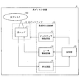
- FIG. 1 is a block diagram illustrating a configuration of an optical disc device according to an embodiment of the present invention. It is a block diagram which shows the detail of a structure of a control part regarding the said optical disk apparatus. It is a flowchart which shows the operation
- FIGS. 1 to 5 An embodiment of the present invention will be described with reference to FIGS. 1 to 5 as follows. Descriptions of configurations other than those described in the following specific embodiments may be omitted as necessary, but are the same as those configurations when described in other embodiments. For convenience of explanation, members having the same functions as those shown in each embodiment are given the same reference numerals, and the explanation thereof is omitted as appropriate.
- FIG. 1 is a schematic diagram showing the structure of the optical disc 100. Further, part (a) of FIG. 1 is a schematic diagram showing a state when the optical disc 100 is viewed from the reproduction light incident side. On the other hand, part (b) of FIG. 1 is a schematic diagram showing a part of the cross-sectional structure of the optical disc 100.
- the optical disc 100 includes one information recording layer L0.
- the optical disc 100 of the present embodiment is a single-layer information recording medium having only one information recording layer L0.
- the optical disc 100 may be a multilayer information recording medium including two or more information recording layers. good.
- an information recording area 103 (FIG. 1 (FIG. 1)) extends in an annular shape from the center (inner periphery side) of the optical disc 100 shown in part (a) of FIG.
- the information recording area 103 is roughly divided into two areas: a management information area 101 and a user area 102.
- the information recording area refers to the direction of the medium surface in which a single film or a multilayer film made of a reflective film or a recording film provided to function as an information recording layer in the information recording layer L0 (reproduction) In-plane direction of the light incident surface).
- Management information area 101 In the management information area (management information recording area) 101, the number of information recording layers, the layer number of each information recording layer, the type of each information recording layer, and the reproduction light emitted from the optical head 11 shown in FIG. Recording power, playback conditions such as the servo system of the optical pickup 12, recording conditions such as the recording power of recording light emitted from the optical head 11 and the irradiation timing of the recording light, and recording on the own medium Various management information related to recording and reproduction of the optical disc 100 such as file management information for managing information in units of files is included.
- the management information area 101 may be an area that does not require tracking control, an area that can be accessed only by focus control, or an area that requires tracking control. Further, a test write area for performing test writing recording (test write) and a defect management area for recording information for defect management of the optical disc 100 may be included.
- the management information area 101 may be composed of only sectors (first recording area, second unit recording area, unit recording area) S (n) to which absolute address information described later is assigned.
- absolute address information is a serial number assigned so as to monotonously increase from a predetermined lower limit value along the reproduction direction. For example, it is a unique number that does not overlap each other and has a predetermined lower limit value (0 ), Etc., a serial number that monotonously increases by one.
- “Absolute address information” may be rephrased as “serial number information”.
- the management information area 101 can be easily accessed according to the same address rule as before and management information can be acquired, so that compatibility with conventional devices can be easily maintained.
- the user area 102 is an area prepared mainly for recording user data, and records various information such as user information such as various software or various contents and accompanying information provided for use of the software or contents. Is done.
- the information recording area 103 is composed of a plurality of concentric ring-shaped tracks T (l) arranged in parallel from the inner circumference side to the outer circumference side of the optical disc 100 shown in the portion (a) of FIG. It is an integer greater than or equal to 0).
- the track T (l) shown in part (a) of FIG. 1 shows only a part of the concentric ring-shaped track T (l). Note that the recording capacities in each track T (l) may or may not coincide with each other on the inner peripheral side and the outer peripheral side.
- the track T (l) is composed of a plurality of sectors (unit recording areas) S (N) (where N is an integer of 0 or more).
- the sector S (N) includes the above-described user information and accompanying information in addition to the address information (absolute address information, relative address information, or auxiliary address information described later), and follows a predetermined order and rule. Stored.
- the sector S (N) includes at least one address recording area in which address information can be recorded. Further, the same address information may be distributed and recorded in a plurality of address recording areas in the sector S (N). Thereby, even when a defect such as a scratch occurs on the optical disc 100, it is possible to prevent the address information from being lost.
- the address information may be recorded directly in the pits, for example, as in a normal ROM type disc (playback-only disc), or on an R type disc (recordable disc) or RE type disc (rewritable disc). As described above, recording may be performed in any form, such as recording by wobbling the track T (l). Further, the address information may be included in the recording mark recorded as in the R type disc and the RE type disc.
- the plurality of sectors S (N) are roughly divided into at least one sector S (n) indicated by a hatched box in FIG. 1A and at least one sector (first) indicated by a plain (white) box. 2 recording areas, first unit recording area, unit recording area) S (m).
- n and m are integers of 0 or more, and N> n and m.
- absolute address information which is a serial number assigned so as to monotonously increase from a predetermined lower limit value along the reproduction direction, is assigned to the sector S (n).
- the sector S (m) includes an address recording area to which address information can be assigned.
- absolute address information is not assigned to this address recording area, or relative address information or Auxiliary address information (however, the absolute address information is set so that the information amount is smaller than when all the sectors S (N) are assigned by serial numbers) is assigned.
- a predetermined lower limit value and a predetermined upper limit value are determined, and a serial number that monotonously increases from the lower limit value toward the upper limit value by one.
- an arbitrary number between the lower limit value and the upper limit value is used as a boundary value, and a number that is greater than or equal to the lower limit value and less than the boundary value is used for allocation of absolute address information. It may be used for allocation of relative address information or auxiliary address information. Conversely, numbers that are greater than or equal to the boundary value and less than or equal to the upper limit value are used for allocation of absolute address information, and numbers that are greater than or equal to the lower limit value and less than the boundary value are used for allocation of relative address information or auxiliary address information. Also good.
- the number of sectors S (m) is increased (the boundary value is shifted to the lower limit value), so that the absolute optical disk 100 can be used as a whole.
- the number of address information (amount of information) can be reduced. For this reason, the amount of information necessary for allocation of address information can be reduced.
- the address information can be allocated to the large-capacity optical disc 100 over the entire information recording area 103 without being insufficient. 100 usable capacities can be increased.
- the conventional address rule can be used easily, so that it is compatible with the conventional equipment.
- the secondary effect is that it is easy to maintain.
- relative address information may be assigned to sector S (m).
- the “relative address information” indicates the relative position of the sector S (m) with respect to the absolute position of the nearest sector S (n) reproduced before reproducing the sector S (m) in the own medium. It is information. In other words, information indicating the relative positional relationship between the absolute position of the closest sector S (n) reproduced before reproduction of the sector S (m) in the own medium and the absolute position of the sector S (m). That is.
- relative address information assigned to a plurality of consecutive sectors S (m)
- the absolute position of the sector S (m) to which the absolute address information is not assigned can be specified using the relative address information assigned to the sector S (m).
- auxiliary address information may be assigned to sector S (m).
- the “auxiliary address information” is an arbitrary number selected from numbers greater than the boundary value and equal to or less than the upper limit value, and before the reproduction of the relative address information and the sector S (m). Any number that has no correlation with the nearest sector S (n) to be reproduced. For example, it is possible to exemplify a constant number regardless of an increase in the sector number, a number that increases monotonously as the sector number increases, and a number that decreases monotonously from a certain number.
- the address information may be recorded directly by pits as in a normal ROM type disc, or may be recorded by wobbling the track T (l) as in an R type disc or an RE type disc. It can be recorded on the optical disc 100 in various other formats. Also, address information may be included in the recording marks recorded on the R-type disc and RE-type disc.
- the number of sectors (total number) is 7 (sector numbers 0 to 6) will be described here.
- the number of sectors is not limited to 7, and an arbitrary number of sectors can be set as necessary.
- the above address information is displayed as information recorded in the sector S (N). Actually, as described above, user information and accompanying information are also included.
- Sectors S (N) are sequentially arranged on a track T (l) (see FIG. 1A) of the optical disc 100 in accordance with a predetermined reproduction order.
- (Recording / reproducing apparatus) 1 rotates the optical disc 100 to acquire address information according to a predetermined reproduction order.
- address information is acquired in order from sector numbers 0 to 6.
- the absolute address information A0 to A6 is serial number information (absolute address information) assigned so as to increase monotonously from a predetermined lower limit value along the reproduction direction, and the auxiliary address information R1 to R2 is auxiliary information that is not the serial number information.
- Address information for example, relative address information.
- Absolute address information A0 to A6 and auxiliary address information R1 to R2 are physical address information different from each other. In other words, absolute address information and auxiliary address information do not have the same number.
- part (a) of FIG. 2 shows an example of address information assigned to a conventional optical disc.
- Absolute address information A0 to A6 is used as address information, and the total number of used address information (hereinafter referred to as the total number of addresses) is 7 and the total number of sectors (hereinafter referred to as the total number of sectors) 7.
- part (b) in FIG. 2 to the part (e) in FIG. 2 show specific examples of address information allocated to the optical disc 100 of the present embodiment.
- auxiliary address information R1 is used in the sector S (N) of two different sector numbers 1 (hereinafter simply referred to as “sector 1”) and the sector 4, and the auxiliary address information R2 is also used in the two different sectors 2 and 5 Used in. That is, the auxiliary address information R 1 (or R 2) arranged at a plurality of locations is address information that is duplicated (same) in the optical disc 100. Note that the auxiliary address information R1 and R2 may be different address information, or may be overlapping (identical) address information.
- part (c) of FIG. 2 shows still another example of address information assigned to the optical disc 100 of the present embodiment.
- absolute address information A0 to A3 and auxiliary address information R1 are used as address information, and the number of addresses used is 5 which is less than the total number of sectors 7.
- the auxiliary address information R 1 is used in three different sectors 3, 4, and 5, and is duplicated (identical) address information in the optical disc 100.
- part (d) of FIG. 2 shows yet another example of address information assigned to the optical disc 100 of the present embodiment.
- absolute address information A0 to A2 and auxiliary address information R1 are used as address information, and the number of addresses used is four, which is smaller than the total number of sectors 7.
- R 1 is used in four different sectors 1, 2, 4, and 5, and is duplicated (identical) address information in the optical disc 100.
- part (e) of FIG. 2 shows still another example of address information assigned to the optical disc 100 of the present embodiment.
- the address information uses absolute address information A0 to A3 and auxiliary address information R1, and the number of addresses used is 5 which is less than the total number of sectors 7.
- the auxiliary address information R ⁇ b> 1 is used in three different sectors 1, 3, and 5, and is an overlapping (identical) address in the optical disc 100.
- the number of addresses used matches the total number of sectors, whereas in the optical disc 100 of the present embodiment, (b) in FIG. ) Portion to the number of addresses used as shown in FIG. 2E is smaller than the total number of sectors.
- the optical disc 100 in the present embodiment is an optical disc on which information is recorded or reproduced by laser light irradiation.
- address information is arranged in each sector S (N), and the address information includes absolute address information and auxiliary address information (or relative address information).
- the absolute address information is a unique value that does not overlap each other, and is a serial number assigned so as to increase monotonously from a predetermined lower limit value along the reproduction direction. Therefore, each sector S ( The playback order of N) can be specified.
- the auxiliary address information may be address information in which at least two overlap (identical).
- the absolute position of the sector S (m) may not be specified only by the auxiliary address information. is there. In such a case, for example, the total number of sectors S (N) existing between sector S (n) and sector S (m) may be counted (calculated). Alternatively, it may be specified how many sectors S (N) the sector S (m) is counted from the sector S (n).
- the absolute position of the sector S (m) can be specified using the above calculation result (specific result) and the absolute position of the sector S (n).
- the number of addresses to be used can be reduced, and the usable capacity of the optical disc can be increased.
- FIG. 2 (b) to FIG. 2 (e) are all sectors S (n) to which absolute address information is assigned and sectors to which auxiliary address information (including relative address information) is assigned.
- a group (recording area group) including at least one S (m) is formed.
- At least one sector S (n) and at least one sector S (n) are reproduced, before the sector S (n + 1) different from the sector S (n) is reproduced.
- the position of an arbitrary sector S (N) in the optical disc 100 can be quickly recognized at any radial position.
- part (b) of FIG. 2 is composed of a total of three sectors, sector 0 assigned with absolute address information A0 and sectors 1 and 2 assigned with auxiliary address information R1 and R2, respectively. Group is included.
- a recording area group consisting of a total of three sectors, sector 3 having absolute address information A1, sector 4 and sector 5 having auxiliary address information R1 and R2, respectively, is repeatedly included according to the playback order. .
- the optical disc 100 By configuring the optical disc 100 to include such a recording area group as a repetition, the absolute address information and the auxiliary address information are arranged at a certain ratio and frequency, and the absolute address information appears evenly in the optical disc 100. The position on the optical disc 100 can be quickly recognized at any radial position.
- the absolute position of the sector S (n) can be specified by simple calculation from the absolute address information.
- the information recording area 103 of the optical disc 100 is composed of the management information area 101 and the user area 102 as shown in FIG.
- the management information area 101 stores management information related to the recognition of the optical disc 100, so as to avoid troubles such as damage to the optical disc 100 due to the optical disc apparatus 1 misrecognizing the optical disc 100. In addition, it is preferable that the management information area 101 can be surely recognized in any optical disc apparatus 1.
- the management information area 101 is arranged according to the conventional address rule as shown in part (a) of FIG. 2, and only the user area 102 is shown in part (b) in FIG. 2 to part (e) in FIG. It is preferable to apply the address rule of this embodiment as shown in FIG.
- the position of the sector S (m) to which the auxiliary address information is assigned cannot be specified, the sector to which the absolute address information is assigned. Since the position of the management information area 101 composed only of S (n) can be recognized, the management information of the optical disc 100 can be reliably recognized.
- FIG. 3 is a block diagram showing a schematic configuration of the optical disc apparatus 1 according to an embodiment of the present invention.
- the optical disc apparatus 1 mainly includes a recording / reproducing circuit group 10, an optical head 11, an optical pickup 12, and a control unit 20.
- the recording / reproducing circuit group 10 mainly includes a pickup driving circuit 13, a laser driving circuit 14, and a reproducing circuit 15.
- the optical disc apparatus 1 is an apparatus for recording or reproducing information with respect to the optical disc 100 such as a DVD or a BD including the optical disc 100.
- control unit 20 moves the optical pickup 12 through the pickup drive circuit 13 to the track T (l) shown in the portion (a) of FIG. 1 of the rotating optical disc 100. It is like that.
- the optical pickup 12 is provided with an optical head 11.
- the control unit 20 moves the optical pickup 12 to a desired recording part (sector S (N)) of the optical disc 100 via the pickup drive circuit 13.
- the control unit 20 sets a recording condition or a reproducing condition via the laser driving circuit 14, and irradiates the optical disk 100 with a recording or reproducing laser beam (light) from the optical head 11.
- a laser beam modulated according to the recording information is irradiated from the optical head 11 to the optical disc 100, and marks and spaces corresponding to the recording information are recorded on the optical disc 100.
- the optical disc apparatus 1 can record information in a desired sector S (N) of the optical disc 100.
- the optical disc apparatus 1 can reproduce the information recorded in the desired sector S (N) of the optical disc 100.
- the control unit 20 includes an address control unit 22 and a recording / reproducing circuit group control unit 21.
- Control unit 20 The control unit 20 performs various controls such as writing information to the optical disc 100, reading information recorded on the optical disc 100, and executing the instruction upon receiving an instruction input by the user.
- the address control unit 22 includes an address acquisition unit (address acquisition unit) 221, an address determination unit (address determination unit) 222, an absolute position specification unit (absolute position specification unit) 223, and a relative position specification unit (relative position specification unit). 224 is operated, and control for specifying address information of each sector S (N) recorded mainly on the optical disc 100 is performed. Further, the address control unit 22 drives the recording / reproducing circuit group 10 via the recording / reproducing circuit group control unit 21 to perform tracking control, focus control, and the like of the optical head 11 to start from each sector S (N) of the optical disc 100. Address information is acquired, and control related to address information such as specifying the absolute position of each sector S (N) is performed. Note that the address control unit 22 specifies the absolute position of each sector S (N) and transfers the specification result to the recording / reproducing circuit group control unit 21.
- the address acquisition unit 221 acquires (reads) the address information of the sector S (N) that is currently reproduced, stores it in the temporary information holding unit 225, and receives the notification that the address information has been acquired by the address determination unit 222. hand over. Further, the address information acquired from the sector S (N) may be the absolute address information described above, or may be auxiliary address information (for example, relative address information).
- the address determination unit 222 When receiving the notification that the address information has been acquired from the address acquisition unit 221, the address determination unit 222 reads the address information stored in the temporary information holding unit 225 by the address acquisition unit 221. The address determination unit 222 determines whether the read address information is absolute address information or auxiliary address information.
- the boundary value of the physical address described above is recorded in advance in a memory (not shown) provided in the address determination unit 222, and if the address information acquired from the sector S (N) is a number less than the boundary value. The absolute address information is determined. If the number is equal to or greater than the boundary value, the auxiliary address information is determined.
- the read address information is absolute address information
- the absolute address information is transferred to the absolute position specifying unit 223.
- the read address information is auxiliary address information
- the auxiliary address information is transferred to the relative position specifying unit 224.
- the relative position specifying unit 224 uses the auxiliary address information (here, relative address information) of the sector S (m) received from the address determining unit 222 to specify the relative position of the sector S (m). Thereafter, the relative position specifying unit 224 passes information on the relative position specifying result to the absolute position specifying unit 223.
- auxiliary address information here, relative address information
- the relative position specifying unit 224 uses the relative address information to calculate the absolute position of the nearest sector S (n) reproduced before reproducing the sector S (m) to which the relative address information is assigned.
- the relative position of the sector S (m) may be specified.
- the relative position of the sector S (m) to which the relative address information is assigned can be reliably specified. . Therefore, if the absolute position of the nearest sector S (n) reproduced before the sector S (m) is identified, the relative position of the sector S (m) can be reliably identified.
- the relative position specifying unit 224 calculates the total number of sectors S (N) existing between the sector S (n) and the sector S (m), and calculates the calculated total number of sectors S (N).
- the relative position of the sector S (m) with respect to the absolute position of the sector S (n) may be used.
- the relative position of the sector S (m) can be specified with a simple configuration. At this time, for example, relative address information does not have to be assigned to the sector S (m), so that the amount of information necessary for assigning address information is further increased compared to the case where relative address information is assigned to the sector S (m). Can be reduced.
- the absolute position specifying unit 223 is based on the absolute address information acquired from the address determination unit 222 and the optical disc 100 of the sector S (n). The absolute position (absolute position) in the inside is specified. Also, when the sector S (N) being reproduced is the sector S (m), information on the relative position specifying result sent from the relative position specifying unit 224 and the absolute address acquired immediately before it (nearest) From the information, the absolute position in the optical disc 100 of the sector S (m) currently being reproduced is specified. The absolute position specified by the absolute position specifying unit 223 is stored in the temporary information holding unit 225.
- the temporary information holding unit 225 temporarily holds the address information acquired by the address acquisition unit 221 and information on the result of specifying the absolute position of each sector S (N).
- the recording / reproducing circuit group control unit 21 performs control of recording or reproducing information on the optical disc 100 based on the absolute position specifying result of each sector S (N) received from the address control unit 22.
- the sector address is an address that corresponds to each sector on a one-to-one basis, and is a number that does not overlap within the optical disc 100. Normally, this is a serial number assigned so that the value increases monotonously by 1 for successive sectors S (N). In this embodiment, it is also a serial number unique to each sector S (N). .
- numerical values related to address information will be described in decimal notation.
- step S101 the address acquisition unit 221 acquires address information from the sector S (N) (reproduction sector) currently being reproduced on the optical disc 100 (address acquisition step). ).
- the address information is formed by direct pits as in the ROM type disk, the track T (l) is wobbled as in the R type disk or the RE type disk, or recorded on the track T (l). It is included as a mark.
- the address acquisition unit 221 can read out necessary address information by the reflected light of the reproduction laser beam from the optical head 11 shown in FIG.
- the acquired address information is held in the temporary information holding unit 225.
- the temporary information holding unit 225 holds a plurality of pieces of address information acquired so far in association with the acquisition order (acquisition time). If the address information of the reproduction sector is acquired from the optical disc 100, the process proceeds to S102.
- the address determination unit 222 first determines whether the address information of the reproduction sector acquired in S101 and held in the temporary information holding unit 225 is absolute address information (address determination step). If YES, the process proceeds to S103, and if NO, the process proceeds to S104.
- the absolute position specifying unit 223 obtains (identifies) and outputs the sector address of the reproduction sector from the absolute address information of the reproduction sector (absolute position identification step). Since the absolute address information and the sector address are unique numbers that do not overlap in the optical disc 100, they always correspond one-to-one.
- the association between the absolute address information and the sector address may be held in advance in a memory (not shown) provided in the absolute position specifying unit 223 as a correspondence table (LUT: Look Up Table).
- the absolute position specifying unit 223 may calculate the sector address from the absolute address information by a predetermined calculation formula. For example, in the example of part (b) of FIG.
- the relative position specifying unit 224 specifies the relative position of the reproduction sector (relative position specifying step).
- the relative position is, for example, information indicating how many sectors the reproduction sector S (m) is located from the sector S (n) to which the latest absolute address information is assigned.
- the relative position specifying unit 224 is specified from the address information of the reproduction sector acquired in S101 and held in the temporary information holding unit 225. What is necessary is just to output a relative position. For example, in the example of the part (b) in FIG.
- the absolute position specifying unit 223 obtains the sector address of the reproduction sector S (N) from the most recently acquired absolute address information held in the temporary information holding unit 225 and the relative position information of the reproduction sector. Output (absolute position specifying step).
- S104 as a method for the relative position specifying unit 224 to acquire the relative position of the reproduction sector S (N), the sector S reproduced in order from the sector S (n) to which the absolute address information acquired most recently is assigned. It is good also as a structure which counts the number of (m). With this configuration, it is not always necessary to record the relative positional relationship with the sector S (n) as relative address information. That is, all the auxiliary address information in the optical disc 100 can be set to the same value. If a specific numerical value that is not used in the absolute address information is set as the same value, the address determination unit 222 compares the address information acquired by the address acquisition unit 221 with the specific numerical value. It is possible to determine whether the address information is absolute address information or auxiliary address information with a very simple configuration.
- an absolute address that can indicate the absolute position in the optical disc but has a limited number of assignments is assigned to only a part of the sectors (first recording area), and the absolute address
- the sector (second recording area) to which is not assigned uses the relative positional relationship with the sector having the immediately preceding absolute address (the relative address is assigned to the sector or the number of scanned sectors is counted). Specify the absolute position.
- the absolute address can be made the same as the conventional address rule, so that it is easy to maintain compatibility with the conventional device, and the number of absolute addresses used at the same time can be reduced. Also, addresses can be allocated over the entire information area without running out of addresses.
- the optical disk (information recording medium) of the present invention is a serial number assigned so as to monotonously increase from a predetermined lower limit along the reproduction direction in an optical disk on which information is recorded or reproduced by laser light irradiation. You may comprise from the 1st recording area where the absolute address is arrange
- a relative address indicating a relative position with respect to the absolute position of the first recording area arranged immediately before may be arranged in the second recording area.
- optical disc of the present invention may include a repetition of a recording area group composed of the N first recording areas and the M second recording areas.
- the management information recording area for recording the management information of the optical disc may be composed of only the first recording area.
- the information recording / reproducing apparatus of the present invention is provided with a first recording area in which an absolute address, which is a serial number assigned so as to monotonously increase from a predetermined lower limit value along the reproduction direction, and an absolute address are arranged.
- Address determining means for specifying may be provided.
- a relative address indicating a relative position to the absolute position of the first recording area disposed immediately before is disposed in the second recording area of the optical disc.
- the relative position acquisition means may acquire the relative address of the second recording area and output it as the relative position.
- the relative position acquisition unit counts the number of recording areas that the laser beam has passed from the first recording area to the second recording area, and calculates the relative position. May be output as
- the information recording / reproducing method of the present invention includes a first recording area in which an absolute address, which is a serial number assigned so as to monotonously increase from a predetermined lower limit value along the reproducing direction, and an absolute address are arranged.
- An information recording / reproducing method for recording / reproducing information on / from an optical disc composed of a second recording area an address obtaining step for obtaining an absolute address of the first recording area, A relative position acquisition step of acquiring a relative position of the second recording area with respect to an absolute position of the first recording area, and by adding the relative position to the absolute address, the position of the second recording area is determined.
- an address determination step for specifying is performed by adding the relative position to the absolute address.
- the computer program of the present invention is a computer program encoded in a computer readable medium, and the information recording / reproducing apparatus includes the readable medium and is executed by a computer. It can also be realized as a computer program that realizes the functions of the respective means in the playback apparatus.
- An information recording medium includes a plurality of unit recording areas, to which absolute address information that is a serial number assigned so as to monotonously increase from a predetermined lower limit value along a reproduction direction is assigned.
- the total number of unit recording areas is smaller than the total number of the plurality of unit recording areas.
- the number of absolute address information (information amount) used as the entire information recording medium can be reduced. For this reason, the amount of information necessary for allocation of address information can be reduced.
- “Absolute address information” is a serial number assigned so as to increase monotonously from a predetermined lower limit value along the reproduction direction.
- the “absolute address information” is a unique number that does not overlap with each other and has a unique lower limit value (0) to 1 A serial number that increases monotonically.
- “Absolute address information” may be rephrased as “serial number information”.
- At least one unit recording area of the plurality of unit recording areas is a first recording area to which the absolute address information is assigned, and the first recording area
- the at least one unit recording area other than may be a second recording area to which the absolute address information is not assigned.
- the information recording medium of the present invention includes a unit recording area (first recording area) to which absolute address information, which is a unique value that does not overlap each other, and a unit recording area to which absolute address information is not assigned (first recording area).
- the second recording area to which absolute address information is not assigned.
- address information can be allocated to a large-capacity information recording medium without any shortage across the entire information recording area.
- the usable capacity of the recording medium can be increased.
- the conventional address rule can be easily used, so that compatibility with conventional equipment is maintained. There is a secondary effect that it becomes easy.
- an information recording medium includes at least one first recording area, and after the reproduction of the at least one first recording area, the first recording area There are a plurality of recording area groups in which a plurality of unit recording areas including at least one of the second recording areas, which are reproduced before another first recording area is reproduced, are arranged according to a predetermined reproduction order. Each of the recording area groups may be repeatedly arranged along the reproduction direction of the plurality of unit recording areas.
- the first recording area is the information. It appears evenly along the playback direction in the recording medium.
- the position of an arbitrary sector (unit recording area) in the optical disk can be quickly recognized at any radial position.
- the information recording medium includes the first recording that is closest to the second recording area and is reproduced before the second recording area is reproduced.
- Relative address information indicating the relative position of the second recording area with respect to the absolute position of the area on the own medium may be assigned.
- the absolute position of the second recording area to which the absolute address information is not assigned can be specified using the relative address information assigned to the second recording area.
- “Relative address information” is information indicating the relative position of the second recording area with respect to the absolute position of the closest first recording area to be reproduced before reproducing the second recording area in the medium. In other words, it is information indicating the relative positional relationship between the absolute position of the closest first recording area to be reproduced before reproducing the second recording area on the own medium and the absolute position of the second recording area. is there.
- the information recording medium has management information for managing information recorded on the own medium in addition to the above configuration.
- the management information recording area to be recorded may be composed of only the first recording area.
- the management information recording area can be easily accessed according to the same address rule as before and management information can be acquired, so that compatibility with conventional devices can be easily maintained.
- the information recording / reproducing apparatus includes a plurality of unit recording areas, and is assigned with absolute address information assigned so as to increase monotonously from a predetermined lower limit value along the reproduction direction.
- An information recording / reproducing apparatus that records or reproduces information on an information recording medium in which the total number of unit recording areas is smaller than the total number of the plurality of unit recording areas.
- Address acquisition means for acquiring address information from one unit recording area
- address determination means for determining whether the address information acquired by the address acquisition means is the absolute address information, and the address by the address determination means If it is determined that the information is not the absolute address information, before the address information is acquired from the first unit recording area
- the relative position specifying means for specifying the relative position of the first unit recording area with respect to the absolute position of the second unit recording area to which the obtained absolute address information is assigned; If it is determined that the address information is not the absolute address information, the absolute position of the first unit recording area in the own medium is determined from the absolute position of the second unit recording area and the relative position of the first unit recording area.
- an absolute position specifying means for specifying.
- the information recording / reproducing method includes a plurality of unit recording areas, and absolute address information assigned so as to monotonously increase from a predetermined lower limit value along the reproduction direction is assigned.
- the relative position specifying step for specifying the relative position of the first unit recording area with respect to the absolute position of the second unit recording area to which the absolute address information acquired before being assigned is assigned, and the address determining step When it is determined that the address information is not the absolute address information, the absolute position of the second unit recording area and the relative position of the first unit recording area are determined in the own medium of the first unit recording area. And an absolute position specifying step for specifying the absolute position.
- the absolute position of the second unit recording area and the second unit recording area of the first unit recording area From the relative position to the absolute position, the absolute position of the first unit recording area can be specified.
- the first unit recording area includes a relative address indicating a relative position of the first unit recording area with respect to an absolute position of the second unit recording area.
- Information is allocated, and the relative position specifying means may specify the relative position of the first unit recording area with respect to the absolute position of the second unit recording area using the relative address information.
- the relative position of the first unit recording area (the first unit recording area relative to the absolute position of the second unit recording area). Relative position). Therefore, if the absolute position of the second unit recording area is specified, the absolute position of the first unit recording area can be reliably specified.
- the relative position specifying unit calculates the total number of unit recording areas existing between the second unit recording area and the first unit recording area. Then, the relative position of the first unit recording area to the absolute position of the second unit recording area may be specified using the calculated total number of the unit recording areas.
- the relative position of the first unit recording area can be specified with a simple configuration. At this time, for example, since relative address information does not have to be assigned to the first unit recording area, the amount of information necessary for assignment of address information is compared with the case where relative address information is assigned to the first unit recording area. Can be further reduced.
- common auxiliary address information for example, a common numerical value
- the first unit recording area to which the common auxiliary address information is assigned is assigned. As the number increases, the amount of information necessary for allocation of address information can be reduced.
- Each means, each function, each process, and each step and each process in the information recording / reproducing apparatus and information recording / reproducing method may be realized by a computer.
- the information recording / reproducing apparatus and the information recording / reproducing method are realized by the computer by causing the computer to realize the functions described above or causing the computer to execute the processes, steps, or steps.
- An information recording / reproducing program and a computer-readable recording medium on which the information recording / reproducing program is recorded fall within the scope of the present invention.
- each block of the optical disc apparatus 1, especially each block of the control unit 20, may be realized by hardware by a logic circuit formed on an integrated circuit (IC chip), or a CPU (Central Processing Unit). You may implement
- IC chip integrated circuit
- CPU Central Processing Unit
- the optical disc apparatus 1 includes a CPU that executes instructions of programs that realize the functions, a ROM (Read Only Memory) that stores the programs, a RAM (Random Access Memory) that expands the programs, the programs, and various types.
- a storage device such as a memory for storing data is provided.
- An object of the present invention is to provide a recording medium in which a program code (execution format program, intermediate code program, source program) of a control program of the optical disc apparatus 1 which is software that realizes the above-described functions is recorded so as to be readable by a computer. This can also be achieved by supplying the optical disc apparatus 1 and reading and executing the program code recorded on the recording medium by the computer (or CPU or MPU).
- Examples of the recording medium include tapes such as a magnetic tape and a cassette tape, a magnetic disk such as a floppy (registered trademark) disk / hard disk, a CD-ROM (Compact Disc-ROM) / MO (Magneto Optical) disc / MD ( Discs including optical discs such as Mini Disc) / DVD / CD-R, cards such as IC cards (including memory cards) / optical cards, semiconductor memories such as mask ROM / EPROM / EEPROM (registered trademark) / flash ROM Or logic circuits such as PLD (Programmable logic device) or FPGA (Field Programmable Gate array).
- tapes such as a magnetic tape and a cassette tape
- a magnetic disk such as a floppy (registered trademark) disk / hard disk
- the optical disc apparatus 1 may be configured to be connectable to a communication network, and the program code may be supplied via the communication network.
- the communication network is not particularly limited as long as it can transmit the program code.
- the Internet intranet, extranet, LAN (Local Area Network), ISDN (Integrated Services Digital Network), VAN (Value Added Network), CATV (Community Antenna TV) communication network, virtual private network (Virtual Private Network), telephone A line network, a mobile communication network, a satellite communication network, etc. can be used.
- the transmission medium constituting the communication network may be any medium that can transmit the program code, and is not limited to a specific configuration or type.
- wired lines such as IEEE 1394, USB, power line carrier, cable TV line, telephone line, and ADSL (Asymmetric Digital Subscriber Line) line
- infrared rays such as IrDA and remote control
- Bluetooth registered trademark
- IEEE 802.11 wireless High Data Rate (NFC), Near Field Communication (NFC), Digital Living Network Alliance (DLNA), mobile phone network, satellite line, and digital terrestrial network.
- NFC High Data Rate
- NFC Near Field Communication
- DLNA Digital Living Network Alliance
- mobile phone network satellite line
- satellite line and digital terrestrial network.
- the present invention can be applied to various recording media.
- the recording medium can be widely applied to various recording media such as the above-described tapes, disks including magnetic disks and optical disks, cards, semiconductor memories, and logic circuits.
- it is suitable for a large-capacity optical disk and an information recording / reproducing apparatus for recording or reproducing information on the optical disk.
- Optical disk device (information recording / reproducing device) DESCRIPTION OF SYMBOLS 10 Recording / reproducing circuit group 11 Optical head 12 Optical pick-up 13 Pick-up drive circuit 14 Laser drive circuit 15 Reproducing circuit 20 Control part 21 Recording / reproducing circuit group control part 22 Address control part 100 Optical disk (information recording medium) 101 Management information area (management information recording area) 102 User area 103 Information recording area 221 Address acquisition unit (address acquisition means) 222 Address determination unit (address determination means) 223 Absolute position specifying part (absolute position specifying means) 224 Relative position specifying unit (relative position specifying means) 225 Temporary information holding unit A0 to A6 Absolute address information L0 Information recording layer R1, R2 Auxiliary address information (relative address information) S (N) sector (unit recording area) S (n) sector (first recording area, second unit recording area, unit recording area) S (m) sector (second recording area, first unit recording area, unit recording area) T (
Landscapes
- Engineering & Computer Science (AREA)
- Signal Processing (AREA)
- Signal Processing For Digital Recording And Reproducing (AREA)
- Indexing, Searching, Synchronizing, And The Amount Of Synchronization Travel Of Record Carriers (AREA)
- Optical Recording Or Reproduction (AREA)
Abstract
光ディスク(100)は、複数のセクタS(N)を含んでおり、絶対アドレス情報が割り当てられているセクタS(n)の総数が、複数のセクタS(N)の総数よりも少ない。
Description
本発明は、情報記録媒体のアドレス配置、および該情報記録媒体に対して情報の記録または再生を行う情報記録再生装置、情報記録再生方法、情報記録再生プログラム、および該情報記録再生プログラムを記録したコンピュータ読み取り可能な記録媒体などに関する。
従来から情報記録の技術分野においては、光ディスクに関する研究が積極的に行われている。この光ディスクは、非接触で記録または再生が行えること、安価な大容量ファイルの実現が可能であること、用途に応じて、再生専用型(ROM;Read only memory)、追記型(R;Recordable または Write once)および書換可能型(RE;Re-writable)の多種のメディア(光ディスク)が存在していることから産業用から民生用まで幅広く応用されている。
上記各種の光ディスクの大容量化は、ディスク上のトラックに書き込まれる情報の情報量を小さくするとともに、記録または再生に用いる光源としてのレーザ光の短波長化を実現し、高開口数(NA;Numerical Aperture)の対物レンズを採用することにより、焦点面での集光スポットサイズを小さくすることによって達成されてきた。
例えば、CD(Compact Disc)では、光透過層となるディスク基板の厚さが約1.2mm、レーザ光の発振波長が約780nm、対物レンズの開口数が0.45であり、650MB(Mega-Byte)の記録容量であった。
一方、DVD(Digital Versatile Disc)では、光透過層となるディスク基板の厚さが約0.6mm、レーザ光の発振波長が約650nm、NAが0.6であり、4.7GB(Giga-Byte)の容量となっている。DVDは、例えば、厚さ約0.6mmのディスク基板を2枚貼り合わせて1.2mmの厚さのディスクとして用いられている。
さらに、高密度のBD(Blu-ray Disc)では、光学記録層上に設けられる光透過層の保護層の厚さを0.1mmに薄くした光ディスクを用いて、レーザ光の発振波長を約405nm、NAを0.85とすることで23GB以上の大容量化を実現している。
ところで、光ディスクには、光ディスク内の物理的な位置を示すアドレス情報が割り当てられている(配置または記録されている)。
アドレス情報は、光ディスク内での各単位記録領域(セクタ)の位置が判別できるように割り当てられており、探索のしやすさの観点から、連続するアドレス情報が付加されている。また、予め定められたアドレス情報の配置に関する規則(以下、単に「アドレス規則」という)に基づいてアドレス情報が割り当てられている。
例えば、特許文献1に開示された光ディスクでは、アドレス情報が情報記録領域の全域にわたってディスクの内周側から外周側に向かうに従って単調増加するように設定することにより、光学ヘッドの移動を簡便にしている。
しかしながら、上記の従来技術のように、光ディスクの情報記録領域の全域にわたってアドレス情報を配置する方法では、光ディスクの大容量化が更に進んだ場合、従来のアドレス規則におけるアドレス情報の下限値~上限値の範囲では全ての情報記録領域に対して、互いに重複しない固有のアドレス情報が割り当てられなくなってしまう可能性があるという問題点がある。
本発明は、上記従来の問題点に鑑みなされたものであって、アドレス情報の割り当てに必要な情報量を削減することができる情報記録媒体および情報記録再生装置などを提供することを目的とする。
上記の課題を解決するために、本発明の一態様に係る情報記録媒体は、複数の単位記録領域を含んでおり、再生方向に沿って所定の下限値から単調に増加するように割り当てられる通し番号である絶対アドレス情報が割り当てられている単位記録領域の総数が、上記複数の単位記録領域の総数よりも少ないことを特徴とする。
上記の課題を解決するために、本発明の一態様に係る情報記録再生装置は、複数の単位記録領域を含んでおり、再生方向に沿って所定の下限値から単調に増加するように割り当てられる通し番号である絶対アドレス情報が割り当てられている単位記録領域の総数が、上記複数の単位記録領域の総数よりも少ない情報記録媒体に対して情報の記録または再生を行う情報記録再生装置であって、上記複数の単位記録領域のうちの第1の単位記録領域からアドレス情報を取得するアドレス取得手段と、上記アドレス取得手段が取得したアドレス情報が上記絶対アドレス情報であるか否かを判定するアドレス判定手段と、上記アドレス判定手段によって上記アドレス情報が上記絶対アドレス情報でないと判定された場合に、上記第1の単位記録領域から上記アドレス情報が取得される前に取得された絶対アドレス情報が割り当てられている第2の単位記録領域の絶対位置に対する、上記第1の単位記録領域の相対位置を特定する相対位置特定手段と、上記アドレス判定手段によって上記アドレス情報が上記絶対アドレス情報でないと判定された場合に、上記第2の単位記録領域の絶対位置と、上記第1の単位記録領域の相対位置とから上記第1の単位記録領域の自媒体における絶対位置を特定する絶対位置特定手段と、を備えていることを特徴とする。
上記の課題を解決するために、本発明の一態様に係る情報記録再生方法は、複数の単位記録領域を含んでおり、再生方向に沿って所定の下限値から単調に増加するように割り当てられる通し番号である絶対アドレス情報が割り当てられている単位記録領域の総数が、上記複数の単位記録領域の総数よりも少ない情報記録媒体に対して情報の記録または再生を行う情報記録再生方法であって、上記複数の単位記録領域のうちの第1の単位記録領域からアドレス情報を取得するアドレス取得ステップと、上記アドレス取得ステップで取得したアドレス情報が上記絶対アドレス情報であるか否かを判定するアドレス判定ステップと、上記アドレス判定ステップで上記アドレス情報が上記絶対アドレス情報でないと判定された場合に、上記第1の単位記録領域から上記アドレス情報が取得される前に取得された絶対アドレス情報が割り当てられている第2の単位記録領域の絶対位置に対する、上記第1の単位記録領域の相対位置を特定する相対位置特定ステップと、上記アドレス判定ステップで上記アドレス情報が上記絶対アドレス情報でないと判定された場合に、上記第2の単位記録領域の絶対位置と、上記第1の単位記録領域の相対位置とから上記第1の単位記録領域の自媒体における絶対位置を特定する絶対位置特定ステップと、を含んでいることを特徴とする。
本発明の一態様によれば、アドレス情報の割り当てに必要な情報量を削減することができるという効果を奏する。
本発明の他の目的、特徴、および優れた点は、以下に示す記載によって十分分かるであろう。また、本発明の利点は、添付図面を参照した次の説明で明白になるであろう。
本発明の一実施形態について図1~図5に基づいて説明すれば、次の通りである。以下の特定の実施形態で説明する構成以外の構成については、必要に応じて説明を省略する場合があるが、他の実施形態で説明されている場合は、その構成と同じである。また、説明の便宜上、各実施形態に示した部材と同一の機能を有する部材については、同一の符号を付し、適宜その説明を省略する。
〔1.光ディスクの構成〕
まず、図1に基づいて、本発明の一実施形態である光ディスク(情報記録媒体)100の構造について説明する。図1は、光ディスク100の構造を示す模式図である。また、図1の(a)部分は、光ディスク100を、再生光入射側から見たときの様子を示す模式図である。一方、図1の(b)部分は、光ディスク100における断面構造の一部を示す模式図である。
まず、図1に基づいて、本発明の一実施形態である光ディスク(情報記録媒体)100の構造について説明する。図1は、光ディスク100の構造を示す模式図である。また、図1の(a)部分は、光ディスク100を、再生光入射側から見たときの様子を示す模式図である。一方、図1の(b)部分は、光ディスク100における断面構造の一部を示す模式図である。
(情報記録層L0)
同図に示すように、光ディスク100は、1層の情報記録層L0を含んでいる。本実施形態の光ディスク100は、情報記録層L0が1層のみである単層の情報記録媒体であるが、光ディスク100は、2層以上の情報記録層を含む多層の情報記録媒体であっても良い。
同図に示すように、光ディスク100は、1層の情報記録層L0を含んでいる。本実施形態の光ディスク100は、情報記録層L0が1層のみである単層の情報記録媒体であるが、光ディスク100は、2層以上の情報記録層を含む多層の情報記録媒体であっても良い。
(情報記録領域103)
情報記録層L0には、図1の(a)部分に示す光ディスク100の中心(内周側)から外周側に向けて円環形状を為して延在する情報記録領域103(図1の(b)部分も併せて参照)が形成されており、この情報記録領域103は、大きく分けて管理情報領域101およびユーザ領域102の2つの領域に分けられる。
情報記録層L0には、図1の(a)部分に示す光ディスク100の中心(内周側)から外周側に向けて円環形状を為して延在する情報記録領域103(図1の(b)部分も併せて参照)が形成されており、この情報記録領域103は、大きく分けて管理情報領域101およびユーザ領域102の2つの領域に分けられる。
ここで、情報記録領域とは、情報記録層L0において、情報記録層として機能するために設けられる反射膜や記録膜などからなる単膜、または、多層膜が設けられている媒体面方向(再生光の入射面の面内方向)の範囲を指す。
(管理情報領域101)
管理情報領域(管理情報記録領域)101には、情報記録層の層数、各情報記録層の層番号、各情報記録層の種類、図3に示す光ヘッド11から出射される再生用の光の再生パワー、光ピックアップ12のサーボ方式などの再生条件、光ヘッド11から出射される記録用の光の記録パワーや記録用の光の照射タイミングなどの記録条件、および、自媒体に記録される情報をファイル単位で管理するためのファイル管理情報など、光ディスク100の記録や再生に関わる各種の管理情報が含まれている。
管理情報領域(管理情報記録領域)101には、情報記録層の層数、各情報記録層の層番号、各情報記録層の種類、図3に示す光ヘッド11から出射される再生用の光の再生パワー、光ピックアップ12のサーボ方式などの再生条件、光ヘッド11から出射される記録用の光の記録パワーや記録用の光の照射タイミングなどの記録条件、および、自媒体に記録される情報をファイル単位で管理するためのファイル管理情報など、光ディスク100の記録や再生に関わる各種の管理情報が含まれている。
管理情報領域101は、トラッキング制御が不要な領域、または、フォーカス制御のみでアクセス可能な領域であってもよいし、トラッキング制御が必要な領域であってもよい。また、試し書き記録(テストライト)を行うためのテストライト領域や、光ディスク100の欠陥管理のための情報を記録する欠陥管理領域が含まれていてもよい。
また、管理情報領域101は、後述する絶対アドレス情報が割り当てられたセクタ(第1記録領域、第2の単位記録領域、単位記録領域)S(n)のみから構成されていても良い。ここで、「絶対アドレス情報」とは、再生方向に沿って所定の下限値から単調に増加するように割り当てられる通し番号であり、例えば、互いに重複しない固有の番号であって所定の下限値(0)から1ずつ単調に増加する通し番号などである。なお、「絶対アドレス情報」を「通し番号情報」と言い換えても良い。
これにより、管理情報領域101には互いに重複しない固有の値である絶対アドレス情報のみが割り当てられる(配置される)。このため、管理情報領域101に関しては従来と同じアドレス規則に従ってアクセスして管理情報を取得することが容易となるため、従来機器との互換性を保つことが容易となる。
(ユーザ領域102)
ユーザ領域102は、主にユーザデータを記録するために用意されている領域であり、各種ソフトウェアまたは各種コンテンツといったユーザ情報や上記ソフトウェアまたはコンテンツの利用に供される付随情報など、様々な情報が記録される。
ユーザ領域102は、主にユーザデータを記録するために用意されている領域であり、各種ソフトウェアまたは各種コンテンツといったユーザ情報や上記ソフトウェアまたはコンテンツの利用に供される付随情報など、様々な情報が記録される。
情報記録領域103は、図1の(a)部分に示す光ディスク100の内周側から外周側に向けて並列する同心円環形状の複数のトラックT(l)から構成される(但し、lは、0以上の整数である)。図1の(a)部分に示すトラックT(l)は、同心円環形状のトラックT(l)の一部のみを示している。なお、各トラックT(l)における記録容量は、内周側と外周側とで一致させても良いし、一致させなくても良い。
このトラックT(l)は、複数のセクタ(単位記録領域)S(N)から構成されている(但し、Nは、0以上の整数である)。
セクタS(N)には、アドレス情報(後述する絶対アドレス情報、相対アドレス情報、もしくは、補助アドレス情報)の他、上述したユーザ情報および付随情報などが含まれており、所定の順序や規則に従って格納される。セクタS(N)には、アドレス情報の記録が可能な少なくとも1つのアドレス記録領域が含まれている。また、同一のアドレス情報を、セクタS(N)内で、複数箇所のアドレス記録領域に分散して記録しても良い。これにより、光ディスク100に対して傷などの欠陥が生じた場合でも、アドレス情報の消失を防止することができる。
また、アドレス情報は、例えば、通常のROM型ディスク(再生専用ディスク)のように直接ピットで記録しても良いし、R型ディスク(追記型ディスク)やRE型ディスク(書換可能型ディスク)のように、トラックT(l)をウォブリングさせて記録するなど、どのような形態で記録しても良い。また、R型ディスクとRE型ディスクのように記録される記録マークにアドレス情報を含めても良い。
複数のセクタS(N)は、大きく分けて、図1の(a)部分に斜線の箱で示す少なくとも1つのセクタS(n)と、無地(白地)の箱で示す少なくとも1つのセクタ(第2記録領域、第1の単位記録領域、単位記録領域)S(m)とを含む。但し、n、mは、0以上の整数であり、N>n、mである。また、SUM(N)でセクタS(N)の総数を表すとき、SUM(N)=SUM(n)+SUM(m)の関係を満たす。
また、セクタS(n)には、再生方向に沿って所定の下限値から単調に増加するように割り当てられる通し番号である絶対アドレス情報が割り当てられる。
一方、セクタS(m)は、アドレス情報が割り当て可能なアドレス記録領域を含んでいるが、本実施形態では、このアドレス記録領域に絶対アドレス情報を割り当てないか、または、後述する相対アドレス情報もしくは補助アドレス情報(但し、絶対アドレス情報を通し番号ですべてのセクタS(N)に割り当てた場合よりも情報量が小さくなるように設定する)を割り当てる。
ここで、通常のアドレス規則で定められている物理アドレスでは、所定の下限値と所定の上限値が定められており、下限値から上限値に向けて1ずつ単調に増加する通し番号とされる。
そこで、例えば、下限値と上限値との間の任意の番号を境界値とし、下限値以上、境界値未満の番号を絶対アドレス情報の割り当てに使用し、境界値以上、上限値以下の番号を相対アドレス情報または補助アドレス情報の割り当てに使用しても良い。また、これとは逆に、境界値以上、上限値以下の番号を絶対アドレス情報の割り当てに使用し、下限値以上、境界値未満の番号を相対アドレス情報または補助アドレス情報の割り当てに使用しても良い。
これにより、特定のセクタS(N)に割り当てられている情報が、絶対アドレス情報および相対アドレス情報(または補助アドレス情報)のいずれであるかを簡単に判別することができる。
これにより、仮にアドレス情報に割り当て可能な全情報量を固定した状態でも、セクタS(m)の数を増加させる(境界値を下限値側にシフトさせる)ことで、光ディスク100全体として使用する絶対アドレス情報の数(情報量)を減少させることができる。このため、アドレス情報の割り当てに必要な情報量を削減することができる。
以上より、アドレス情報の割り当てに必要な情報量を削減することができる。
また、使用する絶対アドレス情報の数を削減することが可能であるため、大容量の光ディスク100に対しても情報記録領域103の全域に渡ってアドレス情報を不足することなく割り当てることができ、光ディスク100の使用可能な容量を増やすことができる。
なお、セクタS(n)に割り当てる絶対アドレス情報については、複数のセクタS(n)の再生順に絶対アドレス情報を割り当てていけば、従来のアドレス規則を簡単に利用できるので従来機器との互換性を保つことが容易となるという副次的な効果を奏する。
また、セクタS(m)に、相対アドレス情報を割り当てても良い。ここで、「相対アドレス情報」とは、セクタS(m)の再生前に再生される最近接のセクタS(n)の自媒体における絶対位置に対する、上記セクタS(m)の相対位置を示す情報のことである。言い換えれば、セクタS(m)の再生前に再生される最近接のセクタS(n)の自媒体における絶対位置と、上記セクタS(m)の絶対位置との相対的な位置関係を示す情報のことである。
なお、複数の連続するセクタS(m)に割り当てる「相対アドレス情報」の例としては、物理アドレスの境界値から開始し、セクタ番号の増加に伴って単調に増加する番号や、物理アドレスの上限値から開始し、セクタ番号の増加に伴って単調に減少する番号などを挙示することができる。
上記構成によれば、絶対アドレス情報が割り当てられていないセクタS(m)の絶対位置を、そのセクタS(m)に割り当てられた相対アドレス情報を用いて特定することができる。
また、セクタS(m)に、補助アドレス情報を割り当てても良い。ここで、「補助アドレス情報」とは、上記の境界値よりも大きく、上限値以下の番号から選択される任意の番号であり、上記の相対アドレス情報や、当該セクタS(m)の再生前に再生される最近接のセクタS(n)と相関関係を持たない任意の番号などである。例えば、セクタ番号の増加に関わらず常に一定の番号や、セクタ番号の増加に伴って、単調に増加し、ある番号から単調に減少する番号などを例示することができる。
また、上記のアドレス情報は、通常のROM型ディスクのように直接ピットで記録しても良いし、R型ディスクやRE型ディスクのように、トラックT(l)をウォブリングさせて記録しても良く、その他の様々な形式で光ディスク100に記録することができる。また、R型ディスクとRE型ディスクでは記録される記録マークにアドレス情報を含めてもよい。
ここで、図2の(a)部分~図2の(e)部分に基づいて、光ディスク100の情報記録領域103におけるアドレス情報の割り当て方の具体例について説明する。
なお、ここでは、簡単のため、セクタ数(総数)が7(セクタ番号0~6)の場合について説明する。しかしながら、セクタ数は7に限られず、必要に応じて任意の数のセクタ数を設定することが可能である。また、本明細書では、説明の便宜上、セクタS(N)に記録される情報としては上記のアドレス情報のみを表示している。実際には、上記に説明した通り、ユーザ情報や付随情報なども含まれている。
セクタS(N)(セクタ番号0~6)は、光ディスク100のトラックT(l)(図1(a)参照)上に所定の再生順序に従って順番に配置されており、後述する光ディスク装置(情報記録再生装置)1は、光ディスク100を回転させて所定の再生順序に従ってアドレス情報を取得する。ここでは、セクタ番号0から6まで、順番にアドレス情報を取得することとする。
また、絶対アドレス情報A0~A6は再生方向に沿って所定の下限値から単調に増加するように割り当てられる通し番号情報(絶対アドレス情報)であり、補助アドレス情報R1~R2は上記通し番号情報でない補助的なアドレス情報(例えば、相対アドレス情報)である。
絶対アドレス情報A0~A6および補助アドレス情報R1~R2はそれぞれ互いに異なる物理アドレス情報である。言い換えれば、絶対アドレス情報と、補助アドレス情報とが同一の番号となることはない。
まず、図2の(a)部分は、従来の光ディスクに割り当てられているアドレス情報の一例を示すものである。アドレス情報として絶対アドレス情報A0~A6を使用しており、使用しているアドレス情報の総数(以下、アドレス総数という)は7とセクタの総数(以下、セクタ総数という)7と一致している。
一方、図2の(b)部分~図2の(e)部分は、本実施形態の光ディスク100に割り当てるアドレス情報の具体例を示す。
図2の(b)部分では、アドレス情報として絶対アドレス情報A0~A2と補助アドレス情報R1~R2を使用しており、使用しているアドレス総数は5とセクタ総数7よりも少ない。補助アドレス情報R1は2つの異なるセクタ番号1のセクタS(N)(以下、単に「セクタ1」という)とセクタ4とで使用されており、補助アドレス情報R2も2つの異なるセクタ2とセクタ5で使用されている。すなわち、複数箇所に配置された補助アドレス情報R1(またはR2)は、光ディスク100内で重複する(同一の)アドレス情報となっている。なお、補助アドレス情報R1とR2とは互いに異なるアドレス情報であっても良いし、重複する(同一の)アドレス情報であっても良い。
また、図2の(c)部分は、本実施形態の光ディスク100に割り当てるアドレス情報の更に別の一例を示すものである。
図2の(c)部分では、アドレス情報として絶対アドレス情報A0~A3と補助アドレス情報R1を使用しており、使用しているアドレス数は5とセクタ総数7よりも少ない。補助アドレス情報R1は3つの異なるセクタ3、セクタ4、セクタ5で使用されており、光ディスク100内で重複する(同一の)アドレス情報となっている。
また、図2の(d)部分は、本実施形態の光ディスク100に割り当てるアドレス情報の更に別の一例を示すものである。
図2の(d)部分では、アドレス情報として絶対アドレス情報A0~A2と補助アドレス情報R1を使用しており、使用しているアドレス数は4とセクタ総数7よりも少ない。R1は4つの異なるセクタ1、セクタ2、セクタ4、セクタ5で使用されており、光ディスク100内で重複する(同一の)アドレス情報となっている。
また、図2の(e)部分は、本実施形態の光ディスク100に割り当てるアドレス情報の更に別の一例を示すものである。
図2の(e)部分では、アドレス情報は絶対アドレス情報A0~A3と補助アドレス情報R1を使用しており、使用しているアドレス数は5とセクタ総数7よりも少ない。補助アドレス情報R1は3つの異なるセクタ1、セクタ3、セクタ5で使用されており、光ディスク100内で重複する(同一の)アドレスとなっている。
つまり、従来の光ディスクにおいては図2の(a)部分で示されるように使用しているアドレス数がセクタ総数と一致しているのに対し、本実施形態の光ディスク100においては図2の(b)部分~図2の(e)で示されるように使用しているアドレス数はセクタ総数よりも少なくなっている。
以上のように、本実施形態における光ディスク100はレーザ光の照射によって情報の記録または再生が行われる光ディスクである。また、各セクタS(N)にアドレス情報が配置されており、アドレス情報は、絶対アドレス情報と補助アドレス情報(または相対アドレス情報)を含んでいる。絶対アドレス情報は、全て互いに重複しない固有の値であり、再生方向に沿って所定の下限値から単調に増加するように割り当てられる通し番号であるため、再生方向に沿って配置された各セクタS(N)の再生順序を特定することができる。
一方、補助アドレス情報は、少なくとも2つが重複する(同一の)アドレス情報であっても良い。このとき、光ディスク100内で同じ補助アドレス情報を持つセクタS(m)が少なくとも2つ以上存在するため、補助アドレス情報だけでは、そのセクタS(m)の絶対位置を特定することができない場合がある。このような場合、例えば、セクタS(n)からセクタS(m)までの間に存在するセクタS(N)の総数をカウント(算出)すれば良い。または、セクタS(m)がセクタS(n)から数えて何番目のセクタS(N)にあたるかを特定しても良い。
これにより、上記の算出結果(特定結果)と、セクタS(n)の絶対位置を用いて、セクタS(m)の絶対位置を特定することができる。
以上により、本実施形態の光ディスク100では、使用するアドレス数を減らすことができ、光ディスクの使用可能な容量を増やすことができる。
なお、図2の(b)部分~図2の(e)部分はいずれも、絶対アドレス情報が割り当てられたセクタS(n)と、補助アドレス情報(相対アドレス情報を含む)が割り当てられたセクタS(m)がそれぞれ少なくとも1つずつ含まれるグループ(記録領域グループ)を構成している。
具体的には、少なくとも1つのセクタS(n)と、当該少なくとも1つのセクタS(n)の再生後、当該セクタS(n)とは別のセクタS(n+1)が再生される前に再生される、少なくとも1つのセクタS(m)と、を含む複数のセクタS(N)が所定の再生順序にしたがって配置された記録領域グループが複数存在し、当該記録領域グループのそれぞれが、上記複数のセクタS(N)の再生方向に沿って繰り返し配置されている。
上記構成によれば、少なくとも1つのセクタS(n)と少なくとも1つのセクタS(m)とが再生順に繰り返し配置される(すなわち、規則的に配置される)ことになるので、セクタS(n)が光ディスク100内で再生方向に沿って均等に出現することになる。
よって、例えば、光ディスク100を例にとると、どの半径位置においても、光ディスク100内の任意のセクタS(N)の位置を迅速に認識することができる。
より具体的には、図2の(b)部分では絶対アドレス情報A0を割り当てられたセクタ0と、補助アドレス情報R1、R2がそれぞれ割り当てられたセクタ1、セクタ2の、合計3セクタから構成されるグループが含まれている。同様に絶対アドレス情報A1を持つセクタ3と、補助アドレス情報R1、R2をそれぞれ持つセクタ4、セクタ5の、同じく合計3セクタから構成される記録領域グループが再生する順序に従って、繰り返し含まれている。このような記録領域グループを繰り返しとして含むよう光ディスク100を構成することで、絶対アドレス情報と補助アドレス情報がそれぞれ一定の割合と頻度で配置され、光ディスク100内で絶対アドレス情報が均等に出現するため、どの半径位置においても、迅速に光ディスク100上の位置を認識することができる。更に、後述するように、絶対アドレス情報が割り当てられたセクタS(n)の場合、絶対アドレス情報から簡単な計算によってセクタS(n)の絶対位置を特定することができる。
なお、前述したとおり、光ディスク100の情報記録領域103は、図1のように管理情報領域101とユーザ領域102で構成されている。
このうち、管理情報領域101は、光ディスク100の認識に関わる管理情報が記録されており、光ディスク装置1が光ディスク100を誤認識することに起因して光ディスク100にダメージを与えるなどのトラブルを避けるため、管理情報領域101についてはどの光ディスク装置1においても確実に認識できることが好ましい。
そこで、管理情報領域101については、図2の(a)部分に示されるような従来のアドレス規則に従って配置し、ユーザ領域102についてのみ、図2の(b)部分~図2の(e)部分に示されるような本実施形態のアドレス規則を適用することが好ましい。これにより、本実施形態のアドレス規則に対応していない、すなわち補助アドレス情報が割り当てられたセクタS(m)の位置を特定することができない光ディスク装置1においても、絶対アドレス情報が割り当てられたセクタS(n)のみから構成される管理情報領域101についてはその位置を認識することができるため、光ディスク100の管理情報を確実に認識することができる。
〔2.光ディスク装置の構成〕
図3に基づいて、本発明の一実施形態である光ディスク装置(情報記録再生装置)1の構成について説明する。図3は、本発明の一実施形態である光ディスク装置1の概要構成を示すブロック図である。
図3に基づいて、本発明の一実施形態である光ディスク装置(情報記録再生装置)1の構成について説明する。図3は、本発明の一実施形態である光ディスク装置1の概要構成を示すブロック図である。
図3に示すように、光ディスク装置1は、主として記録再生回路群10、光ヘッド11、光ピックアップ12および制御部20を備えている。
また、記録再生回路群10は、主としてピックアップ駆動回路13、レーザ駆動回路14および再生回路15を備えている。
また、光ディスク装置1は、光ディスク100を含むDVDやBDなどの光ディスク100に対して情報の記録または再生を行う装置である。
図3に示すように、光ディスク装置1では、回転する光ディスク100の図1の(a)部分に示すトラックT(l)へ、制御部20がピックアップ駆動回路13を介して光ピックアップ12を移動させるようになっている。
光ピックアップ12には、光ヘッド11が設けられている。また、光ディスク装置1は、制御部20がピックアップ駆動回路13を介して光ピックアップ12を光ディスク100の所望の記録部位(セクタS(N))へ移動させる。そして、制御部20がレーザ駆動回路14を介して記録条件または再生条件を設定し、光ヘッド11から記録用または再生用のレーザビーム(光)を光ディスク100に照射するようになっている。
記録時には、記録情報に応じて変調されたレーザビームが光ヘッド11から光ディスク100に照射され、光ディスク100上に記録情報に対応するマークおよびスペースが記録される。これにより、光ディスク装置1は、光ディスク100の所望のセクタS(N)に情報を記録することができる。
再生時には、光ヘッド11が検出した反射光が再生回路15にて再生信号に変換され、制御部20に入力される。これにより、光ディスク装置1は、光ディスク100の所望のセクタS(N)に記録された情報を再生することができる。
次に、図4に基づいて、光ディスク装置1の主要部である制御部20の構成について説明する。制御部20は、アドレス制御部22および記録再生回路群制御部21を備えている。
(制御部20)
制御部20は、光ディスク100に対する情報の書込み、光ディスク100に記録された情報の読み出し、ユーザによる指示の入力を受けて当該指示を実行するなどの様々な制御を行う。
制御部20は、光ディスク100に対する情報の書込み、光ディスク100に記録された情報の読み出し、ユーザによる指示の入力を受けて当該指示を実行するなどの様々な制御を行う。
(アドレス制御部22)
アドレス制御部22は、アドレス取得部(アドレス取得手段)221、アドレス判定部(アドレス判定手段)222、絶対位置特定部(絶対位置特定手段)223、および、相対位置特定部(相対位置特定手段)224、を動作させて、主として光ディスク100に記録されている各セクタS(N)のアドレス情報を特定する制御を行うものである。さらに、アドレス制御部22は、記録再生回路群制御部21を介して記録再生回路群10を駆動し、光ヘッド11のトラッキング制御やフォーカス制御などを行って光ディスク100の各セクタS(N)からアドレス情報を取得し、各セクタS(N)の絶対位置を特定するなどのアドレス情報に関する制御を行う。なお、アドレス制御部22は、各セクタS(N)の絶対位置を特定し、その特定結果を記録再生回路群制御部21に受け渡す。
アドレス制御部22は、アドレス取得部(アドレス取得手段)221、アドレス判定部(アドレス判定手段)222、絶対位置特定部(絶対位置特定手段)223、および、相対位置特定部(相対位置特定手段)224、を動作させて、主として光ディスク100に記録されている各セクタS(N)のアドレス情報を特定する制御を行うものである。さらに、アドレス制御部22は、記録再生回路群制御部21を介して記録再生回路群10を駆動し、光ヘッド11のトラッキング制御やフォーカス制御などを行って光ディスク100の各セクタS(N)からアドレス情報を取得し、各セクタS(N)の絶対位置を特定するなどのアドレス情報に関する制御を行う。なお、アドレス制御部22は、各セクタS(N)の絶対位置を特定し、その特定結果を記録再生回路群制御部21に受け渡す。
アドレス取得部221は、現在再生しているセクタS(N)のアドレス情報を取得(読み出す)し、一時情報保持部225へ記憶し、アドレス情報を取得した旨の通知をアドレス判定部222に受け渡す。また、セクタS(N)から取得されるアドレス情報は、上述した絶対アドレス情報である場合と、補助アドレス情報(例えば、相対アドレス情報)である場合がある。
アドレス判定部222は、アドレス取得部221からアドレス情報を取得した旨の通知を受け取ると、アドレス取得部221が一時情報保持部225に記憶したアドレス情報を読み出す。アドレス判定部222は、読み出したアドレス情報が、絶対アドレス情報および補助アドレス情報のいずれであるかを判定する。
なお、アドレス判定部222に設けられた図示しないメモリには、上述した物理アドレスの境界値が予め記録されており、セクタS(N)から取得したアドレス情報が、境界値未満の番号であれば、絶対アドレス情報と判定し、境界値以上の番号であれば、補助アドレス情報であると判定する。
また、読み出したアドレス情報が、絶対アドレス情報であれば、絶対アドレス情報を絶対位置特定部223に受け渡し、補助アドレス情報であれば、補助アドレス情報を相対位置特定部224に受け渡す。
相対位置特定部224は、アドレス判定部222から受け取ったセクタS(m)の補助アドレス情報(ここでは、相対アドレス情報)を用いて、セクタS(m)の相対位置を特定する。その後、相対位置特定部224は、相対位置の特定結果に関する情報を、絶対位置特定部223に受け渡す。
また、相対位置特定部224は相対アドレス情報を用いて、その相対アドレス情報が割り当てられているセクタS(m)の再生前に再生される最近接のセクタS(n)の絶対位置に対する、上記セクタS(m)の相対位置を特定しても良い。
このように、相対アドレス情報が割り当てられているセクタS(m)から相対アドレス情報を受け取ることにより、確実に相対アドレス情報が割り当てられているセクタS(m)の相対位置を特定することができる。よって、セクタS(m)の再生前に再生される最近接のセクタS(n)の絶対位置が特定されていれば、セクタS(m)の相対位置を確実に特定することができる。
また、相対位置特定部224は、上記セクタS(n)から上記セクタS(m)までの間に存在するセクタS(N)の総数を算出し、算出されたセクタS(N)の総数を用いて、上記セクタS(n)の絶対位置に対する上記セクタS(m)の相対位置を特定しても良い。
上記構成によれば、簡易な構成でセクタS(m)の相対位置を特定することができる。このとき、例えば、セクタS(m)に相対アドレス情報を割り当てなくても良いので、セクタS(m)に相対アドレス情報を割り当てる場合と比較して、アドレス情報の割り当てに必要な情報量をさらに削減することができる。
絶対位置特定部223は、現在再生しているセクタS(N)がセクタS(n)である場合、アドレス判定部222から取得した絶対アドレス情報に基づいて、上記セクタS(n)の光ディスク100内における絶対的な位置(絶対位置)を特定する。また、現在再生しているセクタS(N)がセクタS(m)である場合、相対位置特定部224から送られた相対位置の特定結果に関する情報と、その直前(直近)に取得した絶対アドレス情報とから、現在再生しているセクタS(m)の光ディスク100内における絶対位置を特定する。絶対位置特定部223で特定された絶対位置は、一時情報保持部225に保存される。
一時情報保持部225は、アドレス取得部221が取得したアドレス情報や、各セクタS(N)の絶対位置の特定結果に関する情報などを一時的に保持する。
(記録再生回路群制御部21)
記録再生回路群制御部21は、アドレス制御部22から受け取った各セクタS(N)の絶対位置の特定結果に基づいて、光ディスク100に対する情報の記録または再生の制御などを行う。
記録再生回路群制御部21は、アドレス制御部22から受け取った各セクタS(N)の絶対位置の特定結果に基づいて、光ディスク100に対する情報の記録または再生の制御などを行う。
〔3.情報記録再生装置の動作〕
次に、図5で示すフローチャートに基づいて、本実施形態の光ディスク装置1において、光ディスク100からアドレス情報を再生(取得)し、現在再生中のセクタS(N)のセクタアドレス(絶対位置)を特定する動作のフローについて説明する。なお、セクタアドレスとは、個々のセクタと一対一に対応するアドレスであり、光ディスク100内で重複することがない番号である。通常は連続するセクタS(N)に対して値が1ずつ単調に増加するように付与される通し番号であり、本実施形態においてもそのような各セクタS(N)固有の通し番号であるとする。なお、以下、簡単のため、アドレス情報に関する数値は、10進数表記で説明する。
次に、図5で示すフローチャートに基づいて、本実施形態の光ディスク装置1において、光ディスク100からアドレス情報を再生(取得)し、現在再生中のセクタS(N)のセクタアドレス(絶対位置)を特定する動作のフローについて説明する。なお、セクタアドレスとは、個々のセクタと一対一に対応するアドレスであり、光ディスク100内で重複することがない番号である。通常は連続するセクタS(N)に対して値が1ずつ単調に増加するように付与される通し番号であり、本実施形態においてもそのような各セクタS(N)固有の通し番号であるとする。なお、以下、簡単のため、アドレス情報に関する数値は、10進数表記で説明する。
図5に示すように、ステップS101(以降、ステップは省略)では、アドレス取得部221が、光ディスク100の現在再生中のセクタS(N)(再生セクタ)からアドレス情報を取得する(アドレス取得ステップ)。上記のように、アドレス情報は、ROM型ディスクのように直接ピットで形成したり、R型ディスクやRE型ディスクのようにトラックT(l)をウォブリングさせたり、トラックT(l)上に記録マークとして含めたりしている。これにより、アドレス取得部221は、図3に示す光ヘッド11からの再生用のレーザビームの反射光により、必要なアドレス情報を読み出すことが可能となっている。取得したアドレス情報は、一時情報保持部225に保持される。一時情報保持部225は、これまで取得した複数のアドレス情報を取得順序(取得時刻)と対応付けて保持しておく。光ディスク100より再生セクタのアドレス情報を取得したらS102へ進む。
S102では、アドレス判定部222が、まず、S101で取得し一時情報保持部225に保持した再生セクタのアドレス情報が絶対アドレス情報か否かを判定する(アドレス判定ステップ)。YESの場合はS103へ、NOの場合はS104へ進む。
S103では、絶対位置特定部223が再生セクタの絶対アドレス情報から再生セクタのセクタアドレスを求めて(特定して)出力する(絶対位置特定ステップ)。絶対アドレス情報もセクタアドレスも光ディスク100内では重複しない固有の番号であるため、必ず一対一に対応する。絶対アドレス情報とセクタアドレスの対応付けは、対応表(LUT:Look Up Table)として絶対位置特定部223に設けられた図示しないメモリに予め保持していてもよい。また、絶対位置特定部223が、所定の計算式によって絶対アドレス情報からセクタアドレスを算出するようにしてもよい。例えば、図2の(b)部分の例の場合、上記で説明した通り、絶対アドレス情報が割り当てられているセクタS(0)1つと、補助アドレス情報(ここでは、相対アドレス情報であるものとする)が割り当てられているセクタS(1)、S(2)2つの、合計3セクタから構成される記録領域グループの繰り返しとなっているので、絶対アドレス情報A0=0、絶対アドレス情報A1=1、・・・と絶対アドレス情報が割り当てられていれば、絶対アドレス情報に3を掛けるといった簡単な計算式でセクタS(n)(n=0、3、6・・・)のセクタアドレスを求めることができる。
S104では、相対位置特定部224が再生セクタの相対位置を特定する(相対位置特定ステップ)。相対位置とは、例えば、直近の絶対アドレス情報が割り当てられているセクタS(n)から数えて、再生セクタS(m)が何セクタ離れた位置にあるかを示す情報などである。この相対位置の情報をそのまま相対アドレス情報として割り当てられている光ディスク100を再生する場合、相対位置特定部224は、S101で取得し一時情報保持部225に保持した再生セクタのアドレス情報から特定される相対位置を出力すればよい。例えば、図2の(b)部分の例の場合、補助アドレス情報R1とR2をR1=境界値、R2=境界値+1、と割り当ててあれば、セクタ番号1の相対位置として1、セクタ番号2の相対位置として2をそれぞれ出力する。なお、再生セクタS(N)が絶対アドレス情報を持つセクタS(n)である場合、その相対位置は0と考えればよい。
S105では、絶対位置特定部223が、一時情報保持部225に保持された直近に取得された絶対アドレス情報と、再生セクタの相対位置の情報から、再生セクタS(N)のセクタアドレスを求めて出力する(絶対位置特定ステップ)。図2の(b)部分の例の場合(A0=0、A1=1、R1=境界値+1、R2=境界値+2とする)、各セクタアドレスは、セクタ番号0:3*A0=0、セクタ番号1:3*A0+R1-境界値=1、セクタ番号2:3*A0+R2-境界値=2、セクタ番号3:3*A1=3、セクタ番号4:3*A1+R1-境界値=4、というふうに求められる。
なお、S104において、相対位置特定部224が再生セクタS(N)の相対位置を取得する方法として、直近に取得した絶対アドレス情報が割り当てられているセクタS(n)から、順に再生したセクタS(m)の数をカウントしていく構成としてもよい。この構成であれば、必ずしもセクタS(n)との相対的な位置関係を相対アドレス情報として記録しておく必要はない。すなわち、光ディスク100内の補助アドレス情報を全て同一の値とすることもできる。この同一の値として、絶対アドレス情報に用いられていない特定の数値を設定しておけば、アドレス取得部221で取得したアドレス情報を、アドレス判定部222において、その特定の数値と比較することによって、そのアドレス情報が絶対アドレス情報であるか補助アドレス情報であるかを極めて簡単な構成で判断することが可能となる。
〔本発明の別の表現〕
なお、本発明は、以下のように表現することもできる。
なお、本発明は、以下のように表現することもできる。
すなわち、本発明の光ディスク(情報記録媒体)では、光ディスク内での絶対位置を示せるが割り当て可能な数が限られている絶対アドレスを一部のセクタ(第1記録領域)のみに割り当て、絶対アドレスが割り当てられないセクタ(第2記録領域)は、直前の絶対アドレスを持つセクタとの相対的な位置関係(セクタに相対アドレスを割り当てるか、スキャンしたセクタ数をカウントして特定する)を用いて絶対位置を特定する。
これにより、絶対アドレスについては従来のアドレス規則と同一にできるので従来機器との互換性を保つことが容易となり、同時に使用する絶対アドレスの数を減らせるので、更なる大容量の光ディスクに対しても情報領域の全域に渡ってアドレスを不足することなく割り当てることができる。
また、本発明の光ディスク(情報記録媒体)は、レーザ光の照射によって情報の記録または再生が行われる光ディスクにおいて、再生方向に沿って所定の下限値から単調に増加するように割り当てられる通し番号である絶対アドレスが配置されている第1記録領域と、絶対アドレスが配置されていない第2記録領域とから構成されていても良い。
また、本発明の光ディスクは、上記第2記録領域には、直前に配置されている上記第1記録領域の絶対位置に対する相対位置を示す相対アドレスが配置されていても良い。
また、本発明の光ディスクは、N個の上記第1記録領域と、M個の上記第2記録領域とから構成される記録領域グループの繰り返しを含んでいても良い。
また、本発明の光ディスクは、上記光ディスクの管理情報を記録する管理情報記録領域は、上記第1記録領域のみから構成されていても良い。
また、本発明の情報記録再生装置は、再生方向に沿って所定の下限値から単調に増加するように割り当てられる通し番号である絶対アドレスが配置されている第1記録領域と、絶対アドレスが配置されていない第2記録領域とから構成される光ディスクに対して情報の記録再生を行う情報記録再生装置であって、上記第1記録領域の絶対アドレスを取得するアドレス取得手段と、直前に配置されている上記第1記録領域の絶対位置に対する上記第2記録領域の相対位置を取得する相対位置取得手段と、上記絶対アドレスに対し、上記相対位置を加算することによって、上記第2記録領域の位置を特定するアドレス判定手段とを備えていても良い。
また、本発明の情報記録再生装置は、上記光ディスクの上記第2記録領域には、直前に配置されている上記第1記録領域の絶対位置に対する相対位置を示す相対アドレスが配置されており、上記相対位置取得手段は、上記第2記録領域の相対アドレスを取得して、上記相対位置として出力しても良い。
また、本発明の情報記録再生装置は、上記相対位置取得手段は、上記レーザ光が上記第1記録領域から上記第2記録領域に至るまでに通過した記録領域数をカウントして、上記相対位置として出力しても良い。
また、本発明の情報記録再生方法は、再生方向に沿って所定の下限値から単調に増加するように割り当てられる通し番号である絶対アドレスが配置されている第1記録領域と、絶対アドレスが配置されていない第2記録領域とから構成される光ディスクに対して情報の記録再生を行う情報記録再生方法であって、上記第1記録領域の絶対アドレスを取得するアドレス取得ステップと、直前に配置されている上記第1記録領域の絶対位置に対する上記第2記録領域の相対位置を取得する相対位置取得ステップと、上記絶対アドレスに対し、上記相対位置を加算することによって、上記第2記録領域の位置を特定するアドレス判定ステップと、を備えていても良い。
また、本発明のコンピュータプログラムは、コンピュータ読取可能媒体内に符号化されたコンピュータプログラムであって、上記情報記録再生装置が、上記読取可能媒体を備え、コンピュータによって実行されるときに、上記情報記録再生装置における上記各手段の機能を実現するコンピュータプログラムとして実現することもできる。
〔まとめ〕
本発明の一態様に係る情報記録媒体は、複数の単位記録領域を含んでおり、再生方向に沿って所定の下限値から単調に増加するように割り当てられる通し番号である絶対アドレス情報が割り当てられている単位記録領域の総数が、上記複数の単位記録領域の総数よりも少ない構成である。
本発明の一態様に係る情報記録媒体は、複数の単位記録領域を含んでおり、再生方向に沿って所定の下限値から単調に増加するように割り当てられる通し番号である絶対アドレス情報が割り当てられている単位記録領域の総数が、上記複数の単位記録領域の総数よりも少ない構成である。
上記構成によれば、絶対アドレス情報が割り当てられている単位記録領域の総数を少なくすることで、情報記録媒体全体として使用する絶対アドレス情報の数(情報量)を減少させることができる。このため、アドレス情報の割り当てに必要な情報量を削減することができる。
「絶対アドレス情報」とは、再生方向に沿って所定の下限値から単調に増加するように割り当てられる通し番号であり、例えば、互いに重複しない固有の番号であって所定の下限値(0)から1ずつ単調に増加する通し番号などである。なお、「絶対アドレス情報」を「通し番号情報」と言い換えても良い。
以上より、アドレス情報の割り当てに必要な情報量を削減することができる。
本発明の一態様に係る情報記録媒体は、上記複数の単位記録領域のうち、少なくとも1つの単位記録領域が、上記絶対アドレス情報が割り当てられている第1記録領域であり、当該第1記録領域以外の少なくとも1つの単位記録領域が、上記絶対アドレス情報が割り当てられていない第2記録領域であっても良い。
上記構成によれば、本発明の情報記録媒体は、互いに重複しない固有の値である絶対アドレス情報が割り当てられる単位記録領域(第1記録領域)と、絶対アドレス情報が割り当てられない単位記録領域(第2記録領域)の両方を含んでいる。
これにより、仮にアドレス情報に割り当て可能な全情報量を固定した状態でも、第2記録領域の数を増加させることで、光ディスク全体として使用する絶対アドレス情報の数(情報量)を減少させることができる。このため、アドレス情報の割り当てに必要な情報量を削減することができる。
以上より、アドレス情報の割り当てに必要な情報量を削減することができる。
また、使用する絶対アドレス情報の数を削減することが可能であるため、大容量の情報記録媒体に対しても情報記録領域の全域に渡ってアドレス情報を不足することなく割り当てることができ、情報記録媒体の使用可能な容量を増やすことができる。
なお、第1記録領域に割り当てる絶対アドレス情報については、複数の第1記録領域の再生順に絶対アドレス情報を割り当てていけば、従来のアドレス規則を簡単に利用できるので従来機器との互換性を保つことが容易となるという副次的な効果を奏する。
また、本発明の一態様に係る情報記録媒体は、上記の構成に加えて、少なくとも1つの上記第1記録領域と、当該少なくとも1つの上記第1記録領域の再生後、当該第1記録領域とは別の第1記録領域が再生される前に再生される、少なくとも1つの上記第2記録領域と、を含む複数の単位記録領域が所定の再生順序にしたがって配置された記録領域グループが複数存在し、当該記録領域グループのそれぞれが、上記複数の単位記録領域の再生方向に沿って繰り返し配置されていても良い。
上記構成によれば、少なくとも1つの第1記録領域と少なくとも1つの第2記録領域とが再生順に繰り返し配置される(すなわち、規則的に配置される)ことになるので、第1記録領域が情報記録媒体内で再生方向に沿って均等に出現することになる。
よって、例えば、光ディスクを例にとると、どの半径位置においても、光ディスク内の任意のセクタ(単位記録領域)の位置を迅速に認識することができる。
また、本発明本発明の一態様に係る情報記録媒体は、上記の構成に加えて、上記第2記録領域には、当該第2記録領域の再生前に再生される最近接の上記第1記録領域の自媒体における絶対位置に対する上記第2記録領域の相対位置を示す相対アドレス情報が割り当てられていても良い。
上記構成によれば、絶対アドレス情報が割り当てられていない第2記録領域の絶対位置を、その第2記録領域に割り当てられた相対アドレス情報を用いて特定することができる。
「相対アドレス情報」とは、第2記録領域の再生前に再生される最近接の第1記録領域の自媒体における絶対位置に対する、上記第2記録領域の相対位置を示す情報のことである。言い換えれば、第2記録領域の再生前に再生される最近接の第1記録領域の自媒体における絶対位置と、上記第2記録領域の絶対位置との相対的な位置関係を示す情報のことである。
ここで、上述したように光ディスクの大容量化が更に進んだ場合、全ての情報記録領域に対して固有のアドレス情報が割り当てられなくなってしまう可能性がある。また、このような問題点を解決すべく、仮にアドレス規則を変更した場合、従来のアドレス規則と異なるので、従来機器との互換性を取ることが困難となってしまうという副次的な課題がある。
そこで、このような副次的な課題を解決するために、本発明の一態様に係る情報記録媒体は、上記の構成に加えて、自媒体に記録される情報を管理するための管理情報が記録される管理情報記録領域が、上記第1記録領域のみから構成されていても良い。
上記構成によれば、管理情報記録領域には絶対アドレス情報が割り当てられている第1記録領域のみが配置される。よって、管理情報記録領域に関しては従来と同じアドレス規則に従ってアクセスして管理情報を取得することが容易となるため、従来機器との互換性を保つことが容易となる。
また、本発明の一態様に係る情報記録再生装置は、複数の単位記録領域を含んでおり、再生方向に沿って所定の下限値から単調に増加するように割り当てられる絶対アドレス情報が割り当てられている単位記録領域の総数が、上記複数の単位記録領域の総数よりも少ない情報記録媒体に対して情報の記録または再生を行う情報記録再生装置であって、上記複数の単位記録領域のうちの第1の単位記録領域からアドレス情報を取得するアドレス取得手段と、上記アドレス取得手段が取得したアドレス情報が上記絶対アドレス情報であるか否かを判定するアドレス判定手段と、上記アドレス判定手段によって上記アドレス情報が上記絶対アドレス情報でないと判定された場合に、上記第1の単位記録領域から上記アドレス情報が取得される前に取得された絶対アドレス情報が割り当てられている第2の単位記録領域の絶対位置に対する、上記第1の単位記録領域の相対位置を特定する相対位置特定手段と、上記アドレス判定手段によって上記アドレス情報が上記絶対アドレス情報でないと判定された場合に、上記第2の単位記録領域の絶対位置と、上記第1の単位記録領域の相対位置とから上記第1の単位記録領域の自媒体における絶対位置を特定する絶対位置特定手段と、を備えていても良い。
また、本発明の一態様に係る情報記録再生方法は、複数の単位記録領域を含んでおり、再生方向に沿って所定の下限値から単調に増加するように割り当てられる絶対アドレス情報が割り当てられている単位記録領域の総数が、上記複数の単位記録領域の総数よりも少ない情報記録媒体に対して情報の記録または再生を行う情報記録再生方法であって、上記複数の単位記録領域のうちの第1の単位記録領域からアドレス情報を取得するアドレス取得ステップと、上記アドレス取得ステップで取得したアドレス情報が上記絶対アドレス情報であるか否かを判定するアドレス判定ステップと、上記アドレス判定ステップで上記アドレス情報が上記絶対アドレス情報でないと判定された場合に、上記第1の単位記録領域から上記アドレス情報が取得される前に取得された絶対アドレス情報が割り当てられている第2の単位記録領域の絶対位置に対する、上記第1の単位記録領域の相対位置を特定する相対位置特定ステップと、上記アドレス判定ステップで上記アドレス情報が上記絶対アドレス情報でないと判定された場合に、上記第2の単位記録領域の絶対位置と、上記第1の単位記録領域の相対位置とから上記第1の単位記録領域の自媒体における絶対位置を特定する絶対位置特定ステップと、を含んでいても良い。
上記構成または方法によれば、第1の単位記録領域に絶対アドレス情報が割り当てられていない場合でも、第2の単位記録領域の絶対位置と、第1の単位記録領域の第2の単位記録領域の絶対位置に対する相対位置とから、第1の単位記録領域の絶対位置を特定することができる。
また、本発明の一態様に係る情報記録再生装置は、上記第1の単位記録領域には、上記第2の単位記録領域の絶対位置に対する上記第1の単位記録領域の相対位置を示す相対アドレス情報が割り当てられており、上記相対位置特定手段は、上記相対アドレス情報を用いて、上記第2の単位記録領域の絶対位置に対する上記第1の単位記録領域の相対位置を特定しても良い。
上記構成によれば、第1の単位記録領域から相対アドレス情報を受け取ることにより、確実に第1の単位記録領域の相対位置(第2の単位記録領域の絶対位置に対する第1の単位記録領域の相対位置)を取得することができる。よって、第2の単位記録領域の絶対位置が特定されていれば、第1の単位記録領域の絶対位置を確実に特定することができる。
また、本発明の一態様に係る情報記録再生装置は、上記相対位置特定手段は、上記第2の単位記録領域から上記第1の単位記録領域までの間に存在する単位記録領域の総数を算出し、算出された当該単位記録領域の総数を用いて、上記第2の単位記録領域の絶対位置に対する上記第1の単位記録領域の相対位置を特定しても良い。
上記構成によれば、簡易な構成で第1の単位記録領域の相対位置を特定することができる。このとき、例えば、第1の単位記録領域に相対アドレス情報を割り当てなくても良いので、第1の単位記録領域に相対アドレス情報を割り当てる場合と比較して、アドレス情報の割り当てに必要な情報量をさらに削減することができる。
例えば、複数の第1の単位記録領域に、共通の補助的なアドレス情報(例えば、共通の数値)を割り当てた場合、共通の補助的なアドレス情報が割り当てられている第1の単位記録領域の数が増加すればする程、アドレス情報の割り当てに必要な情報量を削減することができる。
なお、上記情報記録再生装置および情報記録再生方法における各手段、各機能、各処理、ならびに、各ステップおよび各工程のそれぞれは、コンピュータによって実現してもよく、この場合には、コンピュータを各手段として動作させ、コンピュータに上記各機能を実現させ、もしくはコンピュータに上記各処理、上記各ステップまたは上記各工程を実行させることにより上記情報記録再生装置および情報記録再生方法を、コンピュータにて実現させる上記情報記録再生プログラムおよびそれを記録したコンピュータ読み取り可能な記録媒体も、本発明の範疇に入る。
最後に、光ディスク装置1の各ブロック、特に制御部20の各ブロックは、集積回路(ICチップ)上に形成された論理回路によってハードウェア的に実現してもよいし、CPU(Central Processing Unit)を用いてソフトウェア的に実現してもよい。
後者の場合、光ディスク装置1は、各機能を実現するプログラムの命令を実行するCPU、上記プログラムを格納したROM(Read Only Memory)、上記プログラムを展開するRAM(Random Access Memory)、上記プログラムおよび各種データを格納するメモリ等の記憶装置(記録媒体)などを備えている。そして、本発明の目的は、上述した機能を実現するソフトウェアである光ディスク装置1の制御プログラムのプログラムコード(実行形式プログラム、中間コードプログラム、ソースプログラム)をコンピュータで読み取り可能に記録した記録媒体を、光ディスク装置1に供給し、そのコンピュータ(またはCPUやMPU)が記録媒体に記録されているプログラムコードを読み出し実行することによっても、達成可能である。
上記記録媒体としては、例えば、磁気テープやカセットテープ等のテープ類、フロッピー(登録商標)ディスク/ハードディスク等の磁気ディスクやCD-ROM(Compact Disc-ROM)/MO(Magneto Optical)ディスク/MD(Mini Disc)/DVD/CD-R等の光ディスクを含むディスク類、ICカード(メモリカードを含む)/光カード等のカード類、マスクROM/EPROM/EEPROM(登録商標)/フラッシュROM等の半導体メモリ類、あるいはPLD(Programmable logic device)やFPGA(Field Programmable Gate Array)等の論理回路類などを用いることができる。
また、光ディスク装置1を通信ネットワークと接続可能に構成し、上記プログラムコードを通信ネットワークを介して供給してもよい。この通信ネットワークは、プログラムコードを伝送可能であればよく、特に限定されない。例えば、インターネット、イントラネット、エキストラネット、LAN(Local Area Network)、ISDN(Integrated Services Digital Network)、VAN(Value Added Network)、CATV(Community Antenna TV)通信網、仮想専用網(Virtual Private Network)、電話回線網、移動体通信網、衛星通信網等が利用可能である。また、この通信ネットワークを構成する伝送媒体も、プログラムコードを伝送可能な媒体であればよく、特定の構成または種類のものに限定されない。例えば、IEEE1394、USB、電力線搬送、ケーブルTV回線、電話線、ADSL(Asymmetric Digital Subscriber Line)回線等の有線でも、IrDAやリモコンのような赤外線、Bluetooth(登録商標)、IEEE802.11無線、HDR(High Data Rate)、NFC(Near Field Communication)、DLNA(Digital Living Network Alliance)、携帯電話網、衛星回線、地上波デジタル網等の無線でも利用可能
である。
である。
〔付記事項〕
なお、本発明は、上述した実施形態に限定されるものではなく、請求項に示した範囲で種々の変更が可能であり、異なる実施形態にそれぞれ開示された技術的手段を適宜組合せて得られる実施形態についても本発明の技術的範囲に含まれる。さらに、各実施形態にそれぞれ開示された技術的手段を組み合わせることにより、新しい技術的特徴を形成することができる。
なお、本発明は、上述した実施形態に限定されるものではなく、請求項に示した範囲で種々の変更が可能であり、異なる実施形態にそれぞれ開示された技術的手段を適宜組合せて得られる実施形態についても本発明の技術的範囲に含まれる。さらに、各実施形態にそれぞれ開示された技術的手段を組み合わせることにより、新しい技術的特徴を形成することができる。
本発明は、各種の記録媒体に適用することができる。上記記録媒体としては、例えば、上述したテープ類、磁気ディスクおよび光ディスクを含むディスク類、カード類、半導体メモリ類、ならびに、論理回路類などの各種の記録媒体に広く適用することができる。特に、大容量の光ディスクや、該光ディスクに対して情報の記録または再生を行う情報記録再生装置などに好適である。
1 光ディスク装置(情報記録再生装置)
10 記録再生回路群
11 光ヘッド
12 光ピックアップ
13 ピックアップ駆動回路
14 レーザ駆動回路
15 再生回路
20 制御部
21 記録再生回路群制御部
22 アドレス制御部
100 光ディスク(情報記録媒体)
101 管理情報領域(管理情報記録領域)
102 ユーザ領域
103 情報記録領域
221 アドレス取得部(アドレス取得手段)
222 アドレス判定部(アドレス判定手段)
223 絶対位置特定部(絶対位置特定手段)
224 相対位置特定部(相対位置特定手段)
225 一時情報保持部
A0~A6 絶対アドレス情報
L0 情報記録層
R1,R2 補助アドレス情報(相対アドレス情報)
S(N) セクタ(単位記録領域)
S(n) セクタ(第1記録領域、第2の単位記録領域、単位記録領域)
S(m) セクタ(第2記録領域、第1の単位記録領域、単位記録領域)
T(l) トラック
10 記録再生回路群
11 光ヘッド
12 光ピックアップ
13 ピックアップ駆動回路
14 レーザ駆動回路
15 再生回路
20 制御部
21 記録再生回路群制御部
22 アドレス制御部
100 光ディスク(情報記録媒体)
101 管理情報領域(管理情報記録領域)
102 ユーザ領域
103 情報記録領域
221 アドレス取得部(アドレス取得手段)
222 アドレス判定部(アドレス判定手段)
223 絶対位置特定部(絶対位置特定手段)
224 相対位置特定部(相対位置特定手段)
225 一時情報保持部
A0~A6 絶対アドレス情報
L0 情報記録層
R1,R2 補助アドレス情報(相対アドレス情報)
S(N) セクタ(単位記録領域)
S(n) セクタ(第1記録領域、第2の単位記録領域、単位記録領域)
S(m) セクタ(第2記録領域、第1の単位記録領域、単位記録領域)
T(l) トラック
Claims (11)
- 複数の単位記録領域を含んでおり、
再生方向に沿って所定の下限値から単調に増加するように割り当てられる通し番号である絶対アドレス情報が割り当てられている単位記録領域の総数が、上記複数の単位記録領域の総数よりも少ないことを特徴とする情報記録媒体。 - 上記複数の単位記録領域のうち、
少なくとも1つの単位記録領域が、上記絶対アドレス情報が割り当てられている第1記録領域であり、
当該第1記録領域以外の少なくとも1つの単位記録領域が、上記絶対アドレス情報が割り当てられていない第2記録領域であることを特徴とする請求項1に記載の情報記録媒体。 - 少なくとも1つの上記第1記録領域と、
当該少なくとも1つの上記第1記録領域の再生後、当該第1記録領域とは別の第1記録領域が再生される前に再生される、少なくとも1つの上記第2記録領域と、を含む複数の単位記録領域が所定の再生順序にしたがって配置された記録領域グループが複数存在し、当該記録領域グループのそれぞれが、上記複数の単位記録領域の再生方向に沿って繰り返し配置されていることを特徴とする請求項2に記載の情報記録媒体。 - 上記第2記録領域には、当該第2記録領域の再生前に再生される最近接の上記第1記録領域の自媒体における絶対位置に対する上記第2記録領域の相対位置を示す相対アドレス情報が割り当てられていることを特徴とする請求項2または3に記載の情報記録媒体。
- 自媒体に記録される情報を管理するための管理情報が記録される管理情報記録領域が、上記第1記録領域のみから構成されていることを特徴とする請求項2から4までのいずれか1項に記載の情報記録媒体。
- 複数の単位記録領域を含んでおり、再生方向に沿って所定の下限値から単調に増加するように割り当てられる通し番号である絶対アドレス情報が割り当てられている単位記録領域の総数が、上記複数の単位記録領域の総数よりも少ない情報記録媒体に対して情報の記録または再生を行う情報記録再生装置であって、
上記複数の単位記録領域のうちの第1の単位記録領域からアドレス情報を取得するアドレス取得手段と、
上記アドレス取得手段が取得したアドレス情報が上記絶対アドレス情報であるか否かを判定するアドレス判定手段と、
上記アドレス判定手段によって上記アドレス情報が上記絶対アドレス情報でないと判定された場合に、上記第1の単位記録領域から上記アドレス情報が取得される前に取得された絶対アドレス情報が割り当てられている第2の単位記録領域の絶対位置に対する、上記第1の単位記録領域の相対位置を特定する相対位置特定手段と、
上記アドレス判定手段によって上記アドレス情報が上記絶対アドレス情報でないと判定された場合に、上記第2の単位記録領域の絶対位置と、上記第1の単位記録領域の相対位置とから上記第1の単位記録領域の自媒体における絶対位置を特定する絶対位置特定手段と、を備えていることを特徴とする情報記録再生装置。 - 上記第1の単位記録領域には、上記第2の単位記録領域の絶対位置に対する上記第1の単位記録領域の相対位置を示す相対アドレス情報が割り当てられており、
上記相対位置特定手段は、
上記相対アドレス情報を用いて、上記第2の単位記録領域の絶対位置に対する上記第1の単位記録領域の相対位置を特定することを特徴とする請求項6に記載の情報記録再生装置。 - 上記相対位置特定手段は、
上記第2の単位記録領域から上記第1の単位記録領域までの間に存在する単位記録領域の総数を算出し、算出された当該単位記録領域の総数を用いて、上記第2の単位記録領域の絶対位置に対する上記第1の単位記録領域の相対位置を特定することを特徴とする請求項6に記載の情報記録再生装置。 - 複数の単位記録領域を含んでおり、再生方向に沿って所定の下限値から単調に増加するように割り当てられる通し番号である絶対アドレス情報が割り当てられている単位記録領域の総数が、上記複数の単位記録領域の総数よりも少ない情報記録媒体に対して情報の記録または再生を行う情報記録再生方法であって、
上記複数の単位記録領域のうちの第1の単位記録領域からアドレス情報を取得するアドレス取得ステップと、
上記アドレス取得ステップで取得したアドレス情報が上記絶対アドレス情報であるか否かを判定するアドレス判定ステップと、
上記アドレス判定ステップで上記アドレス情報が上記絶対アドレス情報でないと判定された場合に、上記第1の単位記録領域から上記アドレス情報が取得される前に取得された絶対アドレス情報が割り当てられている第2の単位記録領域の絶対位置に対する、上記第1の単位記録領域の相対位置を特定する相対位置特定ステップと、
上記アドレス判定ステップで上記アドレス情報が上記絶対アドレス情報でないと判定された場合に、上記第2の単位記録領域の絶対位置と、上記第1の単位記録領域の相対位置とから上記第1の単位記録領域の自媒体における絶対位置を特定する絶対位置特定ステップと、を含んでいることを特徴とする情報記録再生方法。 - 請求項6から8までのいずれか1項に記載の情報記録再生装置における各手段としてコンピュータを動作させるための情報記録再生プログラム。
- 請求項10に記載の情報記録再生プログラムを記録したコンピュータ読み取り可能な記録媒体。
Applications Claiming Priority (2)
| Application Number | Priority Date | Filing Date | Title |
|---|---|---|---|
| JP2011233322A JP2013093072A (ja) | 2011-10-24 | 2011-10-24 | 情報記録媒体、情報記録再生装置、情報記録再生方法、情報記録再生プログラム、およびコンピュータ読み取り可能な記録媒体 |
| JP2011-233322 | 2011-10-24 |
Publications (1)
| Publication Number | Publication Date |
|---|---|
| WO2013061930A1 true WO2013061930A1 (ja) | 2013-05-02 |
Family
ID=48167761
Family Applications (1)
| Application Number | Title | Priority Date | Filing Date |
|---|---|---|---|
| PCT/JP2012/077249 Ceased WO2013061930A1 (ja) | 2011-10-24 | 2012-10-22 | 情報記録媒体、情報記録再生装置、情報記録再生方法、情報記録再生プログラム、およびコンピュータ読み取り可能な記録媒体 |
Country Status (2)
| Country | Link |
|---|---|
| JP (1) | JP2013093072A (ja) |
| WO (1) | WO2013061930A1 (ja) |
Citations (3)
| Publication number | Priority date | Publication date | Assignee | Title |
|---|---|---|---|---|
| JPH09106636A (ja) * | 1995-10-13 | 1997-04-22 | Nec Corp | Cd規格の光ディスク装置 |
| JP2002032922A (ja) * | 2000-05-12 | 2002-01-31 | Sony Corp | 光ディスク及び光ディスク装置 |
| WO2009066453A1 (ja) * | 2007-11-20 | 2009-05-28 | Panasonic Corporation | 光ディスク、光ディスク装置、光ディスク記録再生方法、集積回路 |
Family Cites Families (5)
| Publication number | Priority date | Publication date | Assignee | Title |
|---|---|---|---|---|
| JPH08167148A (ja) * | 1994-12-13 | 1996-06-25 | Matsushita Electric Ind Co Ltd | 光学式記録再生装置および光学式記録再生方法 |
| JP4576744B2 (ja) * | 2001-04-20 | 2010-11-10 | ソニー株式会社 | 記録媒体、及びその製造方法 |
| CN101073110A (zh) * | 2004-12-07 | 2007-11-14 | 皇家飞利浦电子股份有限公司 | 利用头位置寻址盘存储空间 |
| KR101292728B1 (ko) * | 2006-11-17 | 2013-08-01 | 삼성전자주식회사 | 광 기록 매체, 광 기록 매체 성형 장치 및 방법, 기록 재생장치 및 방법 |
| JP5119283B2 (ja) * | 2010-03-05 | 2013-01-16 | 日立コンシューマエレクトロニクス株式会社 | 記録媒体、再生及び記録方法、再生及び記録装置 |
-
2011
- 2011-10-24 JP JP2011233322A patent/JP2013093072A/ja active Pending
-
2012
- 2012-10-22 WO PCT/JP2012/077249 patent/WO2013061930A1/ja not_active Ceased
Patent Citations (3)
| Publication number | Priority date | Publication date | Assignee | Title |
|---|---|---|---|---|
| JPH09106636A (ja) * | 1995-10-13 | 1997-04-22 | Nec Corp | Cd規格の光ディスク装置 |
| JP2002032922A (ja) * | 2000-05-12 | 2002-01-31 | Sony Corp | 光ディスク及び光ディスク装置 |
| WO2009066453A1 (ja) * | 2007-11-20 | 2009-05-28 | Panasonic Corporation | 光ディスク、光ディスク装置、光ディスク記録再生方法、集積回路 |
Also Published As
| Publication number | Publication date |
|---|---|
| JP2013093072A (ja) | 2013-05-16 |
Similar Documents
| Publication | Publication Date | Title |
|---|---|---|
| KR100957462B1 (ko) | 다층 정보 기록 매체, 기록 방법, 및 재생 방법 | |
| US8077561B2 (en) | Recording medium, apparatus for recording/reproducing data on/from the same and method thereof | |
| KR100808084B1 (ko) | 정보 기록 매체, 기록 방법, 정보 기록 장치, 데이터 구조를 기록한 컴퓨터로 판독 가능한 기록 매체, 및 프로그램을 기록한 컴퓨터로 판독 가능한 기록 매체 | |
| JP2003288759A (ja) | 多層情報記録媒体、記録装置および記録方法 | |
| JPWO2008146459A1 (ja) | 光ディスク装置、及び光ディスク | |
| JP2008527602A (ja) | 記録媒体並びに記録媒体の記録方法及び記録装置 | |
| JP2006500713A (ja) | 欠陥領域管理 | |
| RU2459286C2 (ru) | Устройство для получения относящихся к записи параметров, подходящих к характеристикам записи этого устройства | |
| JP2007012248A (ja) | 多層情報記録媒体および情報装置 | |
| JP2008503843A (ja) | 制御情報を秘匿された状態で記憶するシステム | |
| JPWO2007091620A1 (ja) | 情報記録媒体、情報記録装置及び方法、並びにコンピュータプログラム | |
| WO2013061930A1 (ja) | 情報記録媒体、情報記録再生装置、情報記録再生方法、情報記録再生プログラム、およびコンピュータ読み取り可能な記録媒体 | |
| JP2013235647A (ja) | 多層ディスクに情報を記録する方法および記録装置 | |
| US20060181992A1 (en) | Device and method for recording information | |
| CN100412957C (zh) | 多层信息记录介质及信息装置 | |
| CN101872623A (zh) | 信息存储介质以及记录/再现设备和记录/再现方法 | |
| JP2008505431A (ja) | 追記型記録キャリアに情報を記録する装置及び方法 | |
| JP4494487B2 (ja) | 光記録媒体、光記録再生方法および再生方法 | |
| JP4828548B2 (ja) | 情報記録装置及び方法 | |
| JP4494486B2 (ja) | 光記録媒体、光記録再生方法および再生方法 | |
| JP2009211746A (ja) | 光ディスク記録装置 | |
| JP4108731B2 (ja) | 光記録再生装置、再生装置 | |
| JP4494488B2 (ja) | 光記録再生装置、再生装置 | |
| JP4108730B2 (ja) | 光記録媒体、光記録再生方法、再生方法 | |
| JP4108733B2 (ja) | 光再生装置 |
Legal Events
| Date | Code | Title | Description |
|---|---|---|---|
| 121 | Ep: the epo has been informed by wipo that ep was designated in this application |
Ref document number: 12844618 Country of ref document: EP Kind code of ref document: A1 |
|
| NENP | Non-entry into the national phase |
Ref country code: DE |
|
| 122 | Ep: pct application non-entry in european phase |
Ref document number: 12844618 Country of ref document: EP Kind code of ref document: A1 |