WO2013061638A1 - Led照明装置 - Google Patents
Led照明装置 Download PDFInfo
- Publication number
- WO2013061638A1 WO2013061638A1 PCT/JP2012/061177 JP2012061177W WO2013061638A1 WO 2013061638 A1 WO2013061638 A1 WO 2013061638A1 JP 2012061177 W JP2012061177 W JP 2012061177W WO 2013061638 A1 WO2013061638 A1 WO 2013061638A1
- Authority
- WO
- WIPO (PCT)
- Prior art keywords
- circuit
- charging
- capacitor
- led
- light emitting
- Prior art date
- Legal status (The legal status is an assumption and is not a legal conclusion. Google has not performed a legal analysis and makes no representation as to the accuracy of the status listed.)
- Ceased
Links
Images

Classifications
-
- H—ELECTRICITY
- H05—ELECTRIC TECHNIQUES NOT OTHERWISE PROVIDED FOR
- H05B—ELECTRIC HEATING; ELECTRIC LIGHT SOURCES NOT OTHERWISE PROVIDED FOR; CIRCUIT ARRANGEMENTS FOR ELECTRIC LIGHT SOURCES, IN GENERAL
- H05B45/00—Circuit arrangements for operating light-emitting diodes [LED]
- H05B45/30—Driver circuits
- H05B45/37—Converter circuits
Definitions
- the present invention relates to an illuminating device in which a plurality of LEDs (light emitting diodes) are connected in series, and more particularly to an LED illuminating device having a function of continuing lighting for a certain period of time after a main power supply is stopped.
- LEDs light emitting diodes
- Patent Document 1 discloses that when a fluorescent lamp is lit by a commercial power supply voltage, a charging element (capacitor) is charged, and when the commercial power supply voltage supply is stopped, A lighting fixture that discharges a charging element to light an LED is disclosed.
- Patent Document 2 discloses that the charge charged in the capacitor during the lighting period of the LED fluorescent tube is discharged and applied to the light emitting portion of the LED fluorescent tube.
- Patent Document 2 discloses that the charge charged in the capacitor during the lighting period of the LED fluorescent tube is discharged and applied to the light emitting portion of the LED fluorescent tube.
- Patent Document 2 discloses that the charge charged in the capacitor during the lighting period of the LED fluorescent tube is discharged and applied to the light emitting portion of the LED fluorescent tube.
- an LED lamp is disclosed in which the lighting state of the LED fluorescent tube is maintained.
- Patent Document 3 includes a light source in which a plurality of light emitting elements are connected in series, and a capacitor connected in parallel to any one or a plurality of light emitting elements.
- An illumination device is disclosed in which when the power supply is stopped, power is supplied from the capacitor to keep the light source on for a certain period of time.
- the current decreases and the light quantity of the LED decreases.
- the current rapidly decreases as the voltage decreases due to the relationship between the forward voltage and current. For this reason, the brightness of LED will fall extremely by the fall of the voltage by the resistance of a capacitor charging / discharging circuit.
- an LED lighting device that can be miniaturized is provided.
- the LED illumination device is an LED illumination that applies a voltage from a driving power supply unit, drives a light emitting unit having a plurality of LEDs connected in series, and performs illumination by light emission of the LED.
- a device for driving at least one LED to be lit when the power supply means is stopped, and connected between the light emitting means and the capacitor, and when the light emitting means is driven by the power supply means A charging circuit that charges the capacitor; and a discharge circuit that is connected between the light emitting means and the capacitor and that discharges the capacitor when the power supply means is stopped; and a connection position of the charging circuit with respect to the light emitting means For the light emitting means so that the potential of the charging circuit and the front is Discharge circuit is connected.
- the charging circuit and the discharging circuit of the capacitor for auxiliary lighting are individually configured, and the connection position is set so that the potential at the time of charging and the potential at the time of discharging are different.
- the LED can be well lit when the power is stopped such as a power failure or light extinction.
- the charging circuit and the discharging circuit are configured by the current limiting resistor and the diode, a complicated switching circuit is not required. By changing the connection position of the charging circuit and the discharging circuit, the number of LEDs that are turned on during auxiliary lighting can be increased or decreased, and the brightness can be easily adjusted.
- FIG. 2A shows a basic circuit configuration in which the power supply circuit 10 is connected to the light emitting circuit 30 and the auxiliary lighting circuit 40 via the switch 20.
- the power supply circuit 10 is a circuit that supplies a drive current to the light emitting circuit 30 by performing processing such as step-down, rectification, and smoothing on a commercial power supply, and a known circuit can be applied as it is.
- the switch 20 is for turning on / off the supply of drive current to the light emitting circuit 30 by the power supply circuit 10.
- the light emitting circuit 30 has a configuration in which LEDs 30A, 30B,... 30R, 30S, 30T are connected in series. As the LEDs 30A to 30T, white LEDs are common, but this does not preclude the use of other LEDs such as blue. The number of LEDs to be connected may be appropriately increased or decreased as necessary.
- the auxiliary lighting circuit 40 is a circuit for lighting for a certain period of time during a power failure, and includes a charging circuit 50, a discharging circuit 60, and a capacitor 70.
- the charging circuit 50 includes a charging current limiting resistor 52 connected to the cathode side of the LED 30R or the anode side of the LED 30S, and a charging diode 54 connected to the anode side thereof.
- the discharge circuit 60 includes a discharge current limiting resistor 62 connected to the cathode side of the LED 30S or the anode side of the LED 30T, and a discharge diode 64 connected to the cathode side thereof. That is, the discharge circuit 60 is connected to a lower potential position of the light emitting circuit 30 than the charging circuit 50. Both the cathode side of the charging diode 54 and the anode side of the discharging diode 64 are connected to the plus side of the capacitor 70.
- the negative side of the capacitor 70 is connected to the power supply circuit 10 through the ground.
- capacitor 70 Various types of capacitors may be used as the capacitor 70.
- an electric double layer capacitor or a lithium ion capacitor having a capacity of mF to F order is suitable.
- the switch 20 is turned on. Then, as shown in FIG. 1B, a driving current is supplied from the power supply circuit 10 to the LEDs 30A to 30T of the light emitting circuit 30, and a current flows as shown by an arrow F1A. As a result, the LEDs 30A to 30T emit light. At this time, in the auxiliary lighting circuit 40, the charging diode 54 of the charging circuit 50 becomes conductive, the charging current limited by the charging current limiting resistor 52 flows as indicated by the arrow F1B, and the capacitor 70 is charged.
- the auxiliary lighting circuit 40 when the switch 20 is turned off, the auxiliary lighting circuit 40 is activated in the same manner as during a power failure, and the auxiliary lighting LED 30T emits light for a certain period of time. Accordingly, sudden darkness can be prevented even when the light is intentionally turned off. In this way, not only when a power failure occurs but also when the light is turned off is included when the power is stopped.
- at least one of the charging diode 54 and the discharging diode 64 may be an LED.
- the capacitor charging circuit and the discharging circuit are simply configured with only a capacitor, a resistor, and a diode, and the apparatus can be miniaturized and can be easily incorporated in a lighting fixture.
- the charging / discharging current path is different, and the charging circuit is connected to a position where the potential is higher than that of the discharging circuit. Therefore, the charging time of the capacitor should be relatively shortened and the discharging time should be lengthened. Can do.
- the auxiliary lighting circuit 100 in FIG. 2A is an example in which the charging circuit 50 is connected to the cathode side of the LED 30R as compared with FIG. According to this, the charging voltage becomes higher than that in the first embodiment, and the charging time is further shortened.
- the auxiliary lighting circuit 200 in FIG. 2B is an example in which the charging circuit 50 is connected to the anode side of the LED 30A or the cathode side of the LED 30B as compared with FIG. According to this, the charging voltage becomes higher than that in FIG. 2A, and the charging time is further shortened.
- the auxiliary lighting circuit 300 in FIG. 2 (C) is an example in which the discharge circuit 60 is connected to the anode side of the LED 30R or the cathode side of the LED 30S with respect to the example of FIG. 2 (A). According to this, as compared with FIG. 2A, the LEDs 30S and 30T are turned on when the power is stopped, and the brightness at the time of lighting is improved.
- the auxiliary lighting circuit 400 in FIG. 2 (D) is an example in which the discharge circuit 60 is connected to the cathode side of the LED 30R with respect to the example in FIG. 2 (B). According to this, compared with FIG. 2B, the LEDs 30R, 30S, and 30T come on when the power is stopped, and the brightness at the time of lighting is further improved.
- the charging circuit 50L includes a charging current limiting resistor 52 and a charging LED 54L having an anode connected to the charging current limiting resistor 52.
- the discharge circuit 60L is constituted by a discharge current limiting resistor 62 and a discharge LED 64L connected to the cathode side thereof.
- the discharge circuit 60L is connected to the anode side of the LED 30T of the light emitting circuit 30.
- the capacitor 70 when the capacitor 70 is charged, not only the LEDs 30A to 30T of the light emitting circuit 30 but also the charging LED 54L is lit for a certain time.
- the discharging LED 64L is lit for a certain period of time.
- this invention is not limited to the Example mentioned above, A various change can be added in the range which does not deviate from the summary of this invention.
- the following are also included.
- the number and type of LEDs constituting the light emitting circuit 30 may be appropriately selected as necessary.
- the connection position of the charging circuit and the discharging circuit of the auxiliary lighting circuit may be any position as long as the potential at the time of charging the capacitor is higher than that at the time of discharging, and is not limited to the above embodiment.
- (2) By making the emission color of the LED that is lit during auxiliary lighting different from the other LEDs that are lit during normal lighting, the emission color can be different from that during normal lighting. For example, in the example of FIG. 2 (E), if the discharge LED 64L has a color different from that of the other LEDs, the emission color during auxiliary lighting can be made different from that during normal lighting.
- the charging circuit and the discharging circuit for the auxiliary lighting capacitor are individually configured so that the potential at the time of charging is higher than that at the time of discharging, so that the capacitor is charged in a short time. At the same time, it is possible to perform auxiliary lighting by discharging for a long time when the power is stopped such as a power failure or turning off.
- Embodiments of the present invention are applicable to lighting fixtures in general.
- Power supply circuit 20 Switch 30: Light emitting circuit 30A to 30T: LED 40: auxiliary lighting circuit 50, 50L: charging circuit 52: charging current limiting resistor 54: charging diode 54L: charging LED 60, 60L: discharge circuit 62: discharge current limiting resistor 64: discharge diode 64L: discharge LED 70: Capacitors 100, 200, 300, 400, 500: Auxiliary lighting circuit
Landscapes
- Circuit Arrangement For Electric Light Sources In General (AREA)
Abstract
【課題】小型化が可能なLED照明装置を提供する。【解決手段】スイッチ20をONとして通常点灯を行うと、電源回路10から駆動電流が発光回路30のLED30A~30Tに供給され、矢印F1Aで示すように電流が流れて発光する。このとき、補助点灯回路40では、充電回路50の充電用ダイオード54が導通し、充電電流制限抵抗52によって制限された充電電流が矢印F1Bで示すように流れ、コンデンサ70が充電される。停電が生ずると、放電回路60の放電用ダイオード64が導通してコンデンサ70が放電回路60を介して放電し、矢印F1Cのように電流が流れて発光回路30のLED30Tが発光する。
Description
本発明は、複数のLED(発光ダイオード)が直列接続された照明装置に関し、特に、主電源が停止した後も一定時間は点灯を継続する機能を有するLED照明装置に関する。
停電時の安全を確保するため、主電源が停止した際に、一定時間点灯動作を継続する照明装置が商品化されている。最も簡単な方法としては、停電用の電源として2次電池を使用する方法がある。また、特開2006-139988号公報(特許文献1)には、蛍光ランプを商用電源の電圧によって点灯する際に、充電素子(コンデンサ)を充電し、商用電源の電圧供給が停止したときに、充電素子を放電してLEDを点灯する照明器具が開示されている。
ところで、最近は、蛍光ランプの代わりに、省エネルギー等の観点から、複数のLEDを直列接続した照明装置が提供されている。このようなLED照明装置における点灯継続の先行技術としては、下記特許文献2,3に記載されたものがある。これらのうち、特開2011-82045号公報(特許文献2)には、LED式蛍光管の点灯期間中にコンデンサに充電した電荷を放電して、前記LED式蛍光管の発光部に印加することで、LED式蛍光管の点灯状態を保持するようにしたLEDランプが開示されている。特開2009-170341号公報(特許文献3)には、複数の発光素子が直列接続された光源と、いずれか一又は複数の発光素子に並列に接続されたキャパシタとを備えており、外部からの電力供給が停止したときに、前記キャパシタから電力を供給して前記光源の点灯を一定時間持続させるようにした照明装置が開示されている。
しかしながら、上述した先行技術では、次のような課題がある。
(1)上述した2次電池を使用する方法では、その充電回路や保護回路等が必要となり、照明装置として大型化が避けられない。また、充電・放電を繰り返すことで、2次電池が消耗し、いずれは寿命となるため、定期的に電池交換も必要である。
(2)前記特許文献1の先行技術では、充電回路と放電回路を商用電源の有無によって切り替えるため、回路切替用のスイッチや商用電源の検出回路等を設ける必要があり、照明装置が大型化してしまう。
(3)前記特許文献2の先行技術では、複数のLEDが直列接続された発光部の全体を電源停止時も点灯させるため、コンデンサとして容量の大きなものが必要となり、照明装置の大型化が避けられない。
(4)前記特許文献3の先行技術では、コンデンサに充電する電流経路とコンデンサから放電する電流経路が共通しており、充電電流制限抵抗と放電電流制限抵抗が同じとなる。このため、充電時間を短くするために抵抗値を小さくすると、放電電流が大きくなって停電後の点灯時間が短くなり、逆に、停電後の点灯時間を長くするために抵抗値を大きくすると、充電時間が長くなってしまう。また、電流が小さくなってLEDの光量が低下する。LEDは、その順方向の電圧と電流の関係から、電圧が低くなると電流が急激に減少する。このため、コンデンサ充放電回路の抵抗による電圧の低下によって、LEDの明るさが極端に低下してしまう。
(1)上述した2次電池を使用する方法では、その充電回路や保護回路等が必要となり、照明装置として大型化が避けられない。また、充電・放電を繰り返すことで、2次電池が消耗し、いずれは寿命となるため、定期的に電池交換も必要である。
(2)前記特許文献1の先行技術では、充電回路と放電回路を商用電源の有無によって切り替えるため、回路切替用のスイッチや商用電源の検出回路等を設ける必要があり、照明装置が大型化してしまう。
(3)前記特許文献2の先行技術では、複数のLEDが直列接続された発光部の全体を電源停止時も点灯させるため、コンデンサとして容量の大きなものが必要となり、照明装置の大型化が避けられない。
(4)前記特許文献3の先行技術では、コンデンサに充電する電流経路とコンデンサから放電する電流経路が共通しており、充電電流制限抵抗と放電電流制限抵抗が同じとなる。このため、充電時間を短くするために抵抗値を小さくすると、放電電流が大きくなって停電後の点灯時間が短くなり、逆に、停電後の点灯時間を長くするために抵抗値を大きくすると、充電時間が長くなってしまう。また、電流が小さくなってLEDの光量が低下する。LEDは、その順方向の電圧と電流の関係から、電圧が低くなると電流が急激に減少する。このため、コンデンサ充放電回路の抵抗による電圧の低下によって、LEDの明るさが極端に低下してしまう。
本発明の実施形態により、小型化が可能なLED照明装置を提供する。
本発明の1つの態様に係るLED照明装置は、駆動用の電源手段から電圧を印加して、直列に接続された複数のLEDを有する発光手段を駆動し、LEDの発光による照明を行うLED照明装置であって、前記電源手段の停止時に、少なくとも1つのLEDを駆動して点灯するためのコンデンサと,前記発光手段と前記コンデンサとの間に接続され、前記電源手段による前記発光手段の駆動時に前記コンデンサを充電する充電回路と,前記発光手段と前記コンデンサとの間に接続され、前記電源手段の停止時に前記コンデンサを放電する放電回路と,を備え、前記発光手段に対する前記充電回路の接続位置の電位が、前記発光手段に対する前記放電回路の接続位置の電位よりも高くなるように、前記発光手段に対して、前記充電回路及び前記放電回路が接続されている。
本発明の実施形態によれば、補助点灯用のコンデンサの充電回路と放電回路を個別に構成し、充電時の電位と放電時の電位が異なるように、接続位置を設定することとしたので、停電や消灯といった電源停止時に良好にLED点灯を行うことができる。また、充電回路及び放電回路を電流制限抵抗とダイオードとによって構成することで、複雑な切替回路を必要としない。充電回路と放電回路の接続位置を変更することで、補助点灯時に点灯するLEDの数を増減でき、明るさを簡単に調整することができる。
以下、本発明を実施するための形態を、実施例に基づいて詳細に説明する。
最初に、図1を参照しながら本発明の実施例1について説明する。同図(A)には、基本的な回路構成が示されており、電源回路10がスイッチ20を介して発光回路30及び補助点灯回路40に接続された構成となっている。
これらのうち、電源回路10は、例えば、商用電源に対して、降圧,整流,平滑などの処理を行って、発光回路30に駆動電流を供給する回路で、公知のものをそのまま適用できる。スイッチ20は、電源回路10による発光回路30への駆動電流の供給をON・OFFするためのものである。発光回路30は、LED30A,30B,・・・30R,30S,30Tが直列に接続された構成となっている。LED30A~30Tとしては、白色LEDが一般的であるが、他の青などのLEDを使用することを妨げるものではない。接続するLEDの個数は、必要に応じて適宜増減してよい。
補助点灯回路40は、停電時に一定時間点灯を行うための回路で、充電回路50,放電回路60,コンデンサ70によって構成されている。充電回路50は、LED30Rのカソード側ないしLED30Sのアノード側に接続された充電電流制限抵抗52と、これにアノード側が接続された充電用ダイオード54によって構成されている。放電回路60は、LED30Sのカソード側ないしLED30Tのアノード側に接続された放電電流制限抵抗62と、これにカソード側が接続された放電用ダイオード64によって構成されている。すなわち、放電回路60は、充電回路50と比較して、発光回路30の低い電位の位置に接続されている。充電用ダイオード54のカソード側及び放電用ダイオード64のアノード側は、いずれもコンデンサ70のプラス側に接続されている。コンデンサ70のマイナス側はアースを介して電源回路10に接続されている。
コンデンサ70としては、各種のものを用いてよいが、例えば、mF~Fオーダの容量を持つ電気2重層コンデンサやリチウムイオンコンデンサが好適である。
次に、本実施例の動作を説明する。通常の点灯時は、スイッチ20をONとする。すると、図1(B)に示すように、電源回路10から駆動電流が発光回路30のLED30A~30Tに供給され、矢印F1Aで示すように電流が流れる。これにより、LED30A~30Tが発光する。このとき、補助点灯回路40では、充電回路50の充電用ダイオード54が導通し、充電電流制限抵抗52によって制限された充電電流が矢印F1Bで示すように流れ、コンデンサ70が充電される。
この状態で停電が生じたとすると、電源回路10からの発光回路30に対する通電が停止する。すると、充電回路50によるコンデンサ70の充電が停止されるとともに、放電回路60の放電用ダイオード64が導通するようになり、コンデンサ70が放電回路60を介して放電され、矢印F1Cで示すように電流が流れる。これにより、発光回路30のLED30Tが発光する。これにより、一定時間は、LED30Tの発光が継続されることとなる。なお、停電時のみならず、通常の消灯時も、停電時と同様の動作が行われる。すなわち、スイッチ20がOFFになると、停電時と同様に補助点灯回路40が作動して、一定時間補助点灯用のLED30Tが発光する。従って、意図的に消灯する際にも、急に真っ暗になってしまうことを防止することができる。このように、停電時のみならず消灯時も電源停止時に含まれる。
なお、充電用ダイオード54及び放電用ダイオード64のうちの少なくとも一方のダイオードはLEDであってもよい。
なお、充電用ダイオード54及び放電用ダイオード64のうちの少なくとも一方のダイオードはLEDであってもよい。
このように、本実施例によれば、次のような効果がある。
(1)電気2重層コンデンサ又はリチウムイオンコンデンサを補助点灯用のコンデンサとして用いることとしたので、容量を大きくすることができ、長時間にわたってLEDを点灯させることができる。
(2)コンデンサの充電回路と放電回路は、コンデンサと抵抗とダイオードのみで簡便に構成されており、装置の小型化が可能となって、照明器具への内蔵も容易である。
(3)充放電の電流経路が異なっており、充電回路は放電回路よりも電位が高い位置に接続されているので、相対的に、コンデンサの充電時間を短くするとともに、放電時間を長くすることができる。
(4)充電回路と放電回路の接続位置を変更することで、補助点灯時に発光するLEDの数を増減することができ、明るさの調整が容易である。
(5)電源供給系統に対して、補助点灯を行うためのスイッチの追加などの変更を必要としない。
(1)電気2重層コンデンサ又はリチウムイオンコンデンサを補助点灯用のコンデンサとして用いることとしたので、容量を大きくすることができ、長時間にわたってLEDを点灯させることができる。
(2)コンデンサの充電回路と放電回路は、コンデンサと抵抗とダイオードのみで簡便に構成されており、装置の小型化が可能となって、照明器具への内蔵も容易である。
(3)充放電の電流経路が異なっており、充電回路は放電回路よりも電位が高い位置に接続されているので、相対的に、コンデンサの充電時間を短くするとともに、放電時間を長くすることができる。
(4)充電回路と放電回路の接続位置を変更することで、補助点灯時に発光するLEDの数を増減することができ、明るさの調整が容易である。
(5)電源供給系統に対して、補助点灯を行うためのスイッチの追加などの変更を必要としない。
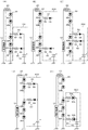
次に、図2を参照しながら、本発明の実施例2について説明する。なお、上述した実施例1に対応する構成要素には同一の符号を用いる。まず、図2(A)の補助点灯回路100は、前記図1に対して、充電回路50をLED30Rのカソード側に接続した例である。これによれば、充電電圧が前記実施例1よりも高くなり、充電時間がより短縮されるようになる。
図2(B)の補助点灯回路200は、前記図1に対して、充電回路50をLED30Aのアノード側ないしLED30Bのカソード側に接続した例である。これによれば、充電電圧が前記図2(A)よりも更に高くなり、充電時間が更に短縮される。
図2(C)の補助点灯回路300は、図2(A)の例に対して、放電回路60をLED30Rのアノード側ないしLED30Sのカソード側に接続した例である。これによれば、図2(A)と比較して、電源停止時にLED30S,30Tが点灯するようになり、点灯時の明るさが向上する。
図2(D)の補助点灯回路400は、図2(B)の例に対して、放電回路60をLED30Rのカソード側に接続した例である。これによれば、図2(B)と比較して、電源停止時にLED30R,LED30S,30Tが点灯するようになり、点灯時の明るさが更に向上する。
図2(E)の補助点灯回路500は、図2(A)の例に対して、充電回路50の充電用ダイオード54と放電回路60の放電用ダイオード64の両方をLEDとした例である。放電用ダイオード64のみをLEDとしてもよい。充電回路50Lは、充電電流制限抵抗52と、これにアノード側が接続された充電用LED54Lによって構成されている。放電回路60Lは、放電電流制限抵抗62と、これにカソード側が接続された放電用LED64Lによって構成されている。また、放電回路60Lは、発光回路30のLED30Tのアノード側に接続されている。本例によれば、コンデンサ70の充電時は、発光回路30のLED30A~30Tのみならず、充電用LED54Lが一定時間点灯する。電源停止時におけるコンデンサ70の放電時は、放電用LED64Lが一定時間点灯する。
なお、本発明は、上述した実施例に限定されるものではなく、本発明の要旨を逸脱しない範囲内において種々変更を加え得ることができる。例えば、以下のものも含まれる。
(1)発光回路30を構成するLEDの個数や種類は、必要に応じて適宜選択してよい。また、補助点灯回路の充電回路及び放電回路の接続位置は、コンデンサ充電時の電位が放電時よりも高ければ、いずれの位置としてもよく、前記実施例に限定されるものではない。
(2)補助点灯時に点灯するLEDの発光色を、通常点灯時に点灯する他のLEDと異なるようにすることで、補助点灯時に通常時と異なる発光色とすることができる。例えば、図2(E)の例において、放電用LED64Lを他のLEDと異なる発色のものとすれば、補助点灯時の発光色を通常点灯時と異なるようにすることができる。
(1)発光回路30を構成するLEDの個数や種類は、必要に応じて適宜選択してよい。また、補助点灯回路の充電回路及び放電回路の接続位置は、コンデンサ充電時の電位が放電時よりも高ければ、いずれの位置としてもよく、前記実施例に限定されるものではない。
(2)補助点灯時に点灯するLEDの発光色を、通常点灯時に点灯する他のLEDと異なるようにすることで、補助点灯時に通常時と異なる発光色とすることができる。例えば、図2(E)の例において、放電用LED64Lを他のLEDと異なる発色のものとすれば、補助点灯時の発光色を通常点灯時と異なるようにすることができる。
本発明の実施形態によれば、補助点灯用のコンデンサの充電回路と放電回路とを個別に構成し、充電時の電位が放電時よりも高くなるようにしたので、コンデンサを短時間で充電するとともに、停電や消灯といった電源停止時は長時間放電して補助点灯を行うことができる。本発明の実施形態は、照明器具一般に適用可能なものである。
10:電源回路
20:スイッチ
30:発光回路
30A~30T:LED
40:補助点灯回路
50,50L:充電回路
52:充電電流制限抵抗
54:充電用ダイオード
54L:充電用LED
60,60L:放電回路
62:放電電流制限抵抗
64:放電用ダイオード
64L:放電用LED
70:コンデンサ
100,200,300,400,500:補助点灯回路
20:スイッチ
30:発光回路
30A~30T:LED
40:補助点灯回路
50,50L:充電回路
52:充電電流制限抵抗
54:充電用ダイオード
54L:充電用LED
60,60L:放電回路
62:放電電流制限抵抗
64:放電用ダイオード
64L:放電用LED
70:コンデンサ
100,200,300,400,500:補助点灯回路
Claims (5)
- 駆動用の電源手段から電圧を印加して、直列に接続された複数のLEDを有する発光手段を駆動し、LEDの発光による照明を行うLED照明装置であって、 前記電源手段の停止時に、少なくとも1つのLEDを駆動して点灯するためのコンデンサと, 前記発光手段と前記コンデンサとの間に接続され、前記電源手段による前記発光手段の駆動時に前記コンデンサを充電する充電回路と, 前記発光手段と前記コンデンサとの間に接続され、前記電源手段の停止時に前記コンデンサを放電する放電回路と,を備え、 前記発光手段に対する前記充電回路の接続位置の電位が、前記発光手段に対する前記放電回路の接続位置の電位よりも高くなるように、前記発光手段に対して、前記充電回路及び前記放電回路が接続されているLED照明装置。
- 前記コンデンサとして、電気2重層コンデンサ又はリチウムイオンコンデンサが使用される、請求項1に記載のLED照明装置。
- 前記充電回路は、充電時に導通するダイオードと該ダイオードに直列に接続された充電電流制限抵抗とを含み、前記放電回路は、放電時に導通するダイオードと該ダイオードに直列に接続された放電電流制限抵抗とを含む、請求項1又は請求項2に記載のLED照明装置。
- 前記充電回路の前記ダイオード及び前記放電回路の前記ダイオードのうちの少なくとも一方のダイオードがLEDである、請求項3に記載のLED照明装置。
- 前記コンデンサが、前記発光手段の前記複数のLED及び前記放電回路の前記LEDのうちの少なくとも1つのLEDを駆動して点灯する、請求項4に記載のLED照明装置。
Priority Applications (2)
| Application Number | Priority Date | Filing Date | Title |
|---|---|---|---|
| CN201280052630.2A CN103891414A (zh) | 2011-10-28 | 2012-04-26 | Led照明装置 |
| TW101138323A TW201330686A (zh) | 2011-10-28 | 2012-10-17 | Led照明裝置 |
Applications Claiming Priority (2)
| Application Number | Priority Date | Filing Date | Title |
|---|---|---|---|
| JP2011237252A JP2013097899A (ja) | 2011-10-28 | 2011-10-28 | Led照明装置 |
| JP2011-237252 | 2011-10-28 |
Publications (1)
| Publication Number | Publication Date |
|---|---|
| WO2013061638A1 true WO2013061638A1 (ja) | 2013-05-02 |
Family
ID=48167484
Family Applications (1)
| Application Number | Title | Priority Date | Filing Date |
|---|---|---|---|
| PCT/JP2012/061177 Ceased WO2013061638A1 (ja) | 2011-10-28 | 2012-04-26 | Led照明装置 |
Country Status (4)
| Country | Link |
|---|---|
| JP (1) | JP2013097899A (ja) |
| CN (1) | CN103891414A (ja) |
| TW (1) | TW201330686A (ja) |
| WO (1) | WO2013061638A1 (ja) |
Cited By (1)
| Publication number | Priority date | Publication date | Assignee | Title |
|---|---|---|---|---|
| WO2015192266A1 (zh) * | 2014-06-17 | 2015-12-23 | 钰瀚科技股份有限公司 | 低闪烁和高功率因素的发光二极管的驱动电路 |
Families Citing this family (1)
| Publication number | Priority date | Publication date | Assignee | Title |
|---|---|---|---|---|
| JP6568481B2 (ja) * | 2016-01-13 | 2019-08-28 | シチズン時計株式会社 | Led電球 |
Citations (4)
| Publication number | Priority date | Publication date | Assignee | Title |
|---|---|---|---|---|
| JPH10164770A (ja) * | 1996-11-26 | 1998-06-19 | Matsushita Electric Works Ltd | 照明装置 |
| JP2009170341A (ja) * | 2008-01-18 | 2009-07-30 | Nitto Kogaku Kk | 照明装置 |
| JP2009205850A (ja) * | 2008-02-26 | 2009-09-10 | Panasonic Electric Works Co Ltd | 照明装置 |
| JP2011082045A (ja) * | 2009-10-08 | 2011-04-21 | Igarashi Bussan Kk | Ledランプ |
Family Cites Families (3)
| Publication number | Priority date | Publication date | Assignee | Title |
|---|---|---|---|---|
| CN201134948Y (zh) * | 2007-02-25 | 2008-10-15 | 谭蜀君 | 具有节能应急照明为一体的节能灯 |
| CN102081880A (zh) * | 2009-11-30 | 2011-06-01 | 英业达股份有限公司 | 显示装置 |
| CN201967222U (zh) * | 2011-04-28 | 2011-09-07 | 李旭亮 | 一种led灯具及led开关控制装置 |
-
2011
- 2011-10-28 JP JP2011237252A patent/JP2013097899A/ja active Pending
-
2012
- 2012-04-26 WO PCT/JP2012/061177 patent/WO2013061638A1/ja not_active Ceased
- 2012-04-26 CN CN201280052630.2A patent/CN103891414A/zh active Pending
- 2012-10-17 TW TW101138323A patent/TW201330686A/zh unknown
Patent Citations (4)
| Publication number | Priority date | Publication date | Assignee | Title |
|---|---|---|---|---|
| JPH10164770A (ja) * | 1996-11-26 | 1998-06-19 | Matsushita Electric Works Ltd | 照明装置 |
| JP2009170341A (ja) * | 2008-01-18 | 2009-07-30 | Nitto Kogaku Kk | 照明装置 |
| JP2009205850A (ja) * | 2008-02-26 | 2009-09-10 | Panasonic Electric Works Co Ltd | 照明装置 |
| JP2011082045A (ja) * | 2009-10-08 | 2011-04-21 | Igarashi Bussan Kk | Ledランプ |
Cited By (1)
| Publication number | Priority date | Publication date | Assignee | Title |
|---|---|---|---|---|
| WO2015192266A1 (zh) * | 2014-06-17 | 2015-12-23 | 钰瀚科技股份有限公司 | 低闪烁和高功率因素的发光二极管的驱动电路 |
Also Published As
| Publication number | Publication date |
|---|---|
| CN103891414A (zh) | 2014-06-25 |
| JP2013097899A (ja) | 2013-05-20 |
| TW201330686A (zh) | 2013-07-16 |
Similar Documents
| Publication | Publication Date | Title |
|---|---|---|
| JP4952292B2 (ja) | Led点灯装置及び照明装置システム | |
| CN201663727U (zh) | 旁路保护电路及使用其的发光二极管驱动装置 | |
| JP2008263203A (ja) | 高効率acled駆動回路 | |
| WO2012128245A1 (ja) | 直管形led照明灯 | |
| CN110139422A (zh) | 限流型电子整流器及运用该限流型电子整流器的灯管 | |
| CN201318576Y (zh) | 一种led日光灯管 | |
| KR101435853B1 (ko) | 발광 다이오드 구동 장치 | |
| JP2010182656A (ja) | 蛍光ランプ形状のledランプ | |
| CN103152901B (zh) | 发光二极管灯具 | |
| JP6353992B1 (ja) | グロー低減が改善されたled光源 | |
| JP5811505B2 (ja) | 照明装置 | |
| WO2013061638A1 (ja) | Led照明装置 | |
| CN102625524B (zh) | 点灯装置以及照明装置 | |
| JP2017174680A (ja) | Ledランプ及びled照明装置 | |
| EP3032696B1 (en) | Emergency lighting unit | |
| US20090001900A1 (en) | Device for Fluorescent Tube Armatures | |
| US10645782B2 (en) | Solid-state lighting with emergency power management | |
| TWI410177B (zh) | 旁路保護電路及使用其的發光二極體驅動裝置 | |
| JP2011090970A (ja) | Led非常用照明装置 | |
| JP2012009348A (ja) | 照明点灯装置及び照明器具 | |
| EP2642825A1 (en) | Lighting circuit and luminaire | |
| US9107255B2 (en) | Light-emitting diode light tube driving circuit | |
| JP5457875B2 (ja) | 点灯装置及びそれを用いた照明器具 | |
| KR20140093456A (ko) | 발광 다이오드 조명 장치 | |
| KR101430732B1 (ko) | 점등 모듈 및 이를 포함하는 점등 장치 |
Legal Events
| Date | Code | Title | Description |
|---|---|---|---|
| 121 | Ep: the epo has been informed by wipo that ep was designated in this application |
Ref document number: 12844427 Country of ref document: EP Kind code of ref document: A1 |
|
| NENP | Non-entry into the national phase |
Ref country code: DE |
|
| 122 | Ep: pct application non-entry in european phase |
Ref document number: 12844427 Country of ref document: EP Kind code of ref document: A1 |