WO2013061629A1 - 線材の軟化装置及び線材の軟化方法 - Google Patents
線材の軟化装置及び線材の軟化方法 Download PDFInfo
- Publication number
- WO2013061629A1 WO2013061629A1 PCT/JP2012/055032 JP2012055032W WO2013061629A1 WO 2013061629 A1 WO2013061629 A1 WO 2013061629A1 JP 2012055032 W JP2012055032 W JP 2012055032W WO 2013061629 A1 WO2013061629 A1 WO 2013061629A1
- Authority
- WO
- WIPO (PCT)
- Prior art keywords
- sheave
- wire
- energization
- cooling liquid
- liquid level
- Prior art date
- Legal status (The legal status is an assumption and is not a legal conclusion. Google has not performed a legal analysis and makes no representation as to the accuracy of the status listed.)
- Ceased
Links
Images




Classifications
-
- C—CHEMISTRY; METALLURGY
- C21—METALLURGY OF IRON
- C21D—MODIFYING THE PHYSICAL STRUCTURE OF FERROUS METALS; GENERAL DEVICES FOR HEAT TREATMENT OF FERROUS OR NON-FERROUS METALS OR ALLOYS; MAKING METAL MALLEABLE, e.g. BY DECARBURISATION OR TEMPERING
- C21D9/00—Heat treatment, e.g. annealing, hardening, quenching or tempering, adapted for particular articles; Furnaces therefor
- C21D9/0062—Heat-treating apparatus with a cooling or quenching zone
-
- C—CHEMISTRY; METALLURGY
- C21—METALLURGY OF IRON
- C21D—MODIFYING THE PHYSICAL STRUCTURE OF FERROUS METALS; GENERAL DEVICES FOR HEAT TREATMENT OF FERROUS OR NON-FERROUS METALS OR ALLOYS; MAKING METAL MALLEABLE, e.g. BY DECARBURISATION OR TEMPERING
- C21D9/00—Heat treatment, e.g. annealing, hardening, quenching or tempering, adapted for particular articles; Furnaces therefor
- C21D9/52—Heat treatment, e.g. annealing, hardening, quenching or tempering, adapted for particular articles; Furnaces therefor for wires; for strips ; for rods of unlimited length
- C21D9/54—Furnaces for treating strips or wire
- C21D9/56—Continuous furnaces for strip or wire
- C21D9/573—Continuous furnaces for strip or wire with cooling
-
- C—CHEMISTRY; METALLURGY
- C21—METALLURGY OF IRON
- C21D—MODIFYING THE PHYSICAL STRUCTURE OF FERROUS METALS; GENERAL DEVICES FOR HEAT TREATMENT OF FERROUS OR NON-FERROUS METALS OR ALLOYS; MAKING METAL MALLEABLE, e.g. BY DECARBURISATION OR TEMPERING
- C21D1/00—General methods or devices for heat treatment, e.g. annealing, hardening, quenching or tempering
- C21D1/34—Methods of heating
- C21D1/40—Direct resistance heating
-
- C—CHEMISTRY; METALLURGY
- C21—METALLURGY OF IRON
- C21D—MODIFYING THE PHYSICAL STRUCTURE OF FERROUS METALS; GENERAL DEVICES FOR HEAT TREATMENT OF FERROUS OR NON-FERROUS METALS OR ALLOYS; MAKING METAL MALLEABLE, e.g. BY DECARBURISATION OR TEMPERING
- C21D9/00—Heat treatment, e.g. annealing, hardening, quenching or tempering, adapted for particular articles; Furnaces therefor
- C21D9/52—Heat treatment, e.g. annealing, hardening, quenching or tempering, adapted for particular articles; Furnaces therefor for wires; for strips ; for rods of unlimited length
- C21D9/525—Heat treatment, e.g. annealing, hardening, quenching or tempering, adapted for particular articles; Furnaces therefor for wires; for strips ; for rods of unlimited length for wire, for rods
-
- C—CHEMISTRY; METALLURGY
- C21—METALLURGY OF IRON
- C21D—MODIFYING THE PHYSICAL STRUCTURE OF FERROUS METALS; GENERAL DEVICES FOR HEAT TREATMENT OF FERROUS OR NON-FERROUS METALS OR ALLOYS; MAKING METAL MALLEABLE, e.g. BY DECARBURISATION OR TEMPERING
- C21D9/00—Heat treatment, e.g. annealing, hardening, quenching or tempering, adapted for particular articles; Furnaces therefor
- C21D9/52—Heat treatment, e.g. annealing, hardening, quenching or tempering, adapted for particular articles; Furnaces therefor for wires; for strips ; for rods of unlimited length
- C21D9/54—Furnaces for treating strips or wire
- C21D9/56—Continuous furnaces for strip or wire
- C21D9/573—Continuous furnaces for strip or wire with cooling
- C21D9/5732—Continuous furnaces for strip or wire with cooling of wires; of rods
-
- C—CHEMISTRY; METALLURGY
- C21—METALLURGY OF IRON
- C21D—MODIFYING THE PHYSICAL STRUCTURE OF FERROUS METALS; GENERAL DEVICES FOR HEAT TREATMENT OF FERROUS OR NON-FERROUS METALS OR ALLOYS; MAKING METAL MALLEABLE, e.g. BY DECARBURISATION OR TEMPERING
- C21D9/00—Heat treatment, e.g. annealing, hardening, quenching or tempering, adapted for particular articles; Furnaces therefor
- C21D9/52—Heat treatment, e.g. annealing, hardening, quenching or tempering, adapted for particular articles; Furnaces therefor for wires; for strips ; for rods of unlimited length
- C21D9/54—Furnaces for treating strips or wire
- C21D9/56—Continuous furnaces for strip or wire
- C21D9/62—Continuous furnaces for strip or wire with direct resistance heating
-
- C—CHEMISTRY; METALLURGY
- C22—METALLURGY; FERROUS OR NON-FERROUS ALLOYS; TREATMENT OF ALLOYS OR NON-FERROUS METALS
- C22F—CHANGING THE PHYSICAL STRUCTURE OF NON-FERROUS METALS AND NON-FERROUS ALLOYS
- C22F1/00—Changing the physical structure of non-ferrous metals or alloys by heat treatment or by hot or cold working
- C22F1/08—Changing the physical structure of non-ferrous metals or alloys by heat treatment or by hot or cold working of copper or alloys based thereon
-
- C—CHEMISTRY; METALLURGY
- C21—METALLURGY OF IRON
- C21D—MODIFYING THE PHYSICAL STRUCTURE OF FERROUS METALS; GENERAL DEVICES FOR HEAT TREATMENT OF FERROUS OR NON-FERROUS METALS OR ALLOYS; MAKING METAL MALLEABLE, e.g. BY DECARBURISATION OR TEMPERING
- C21D1/00—General methods or devices for heat treatment, e.g. annealing, hardening, quenching or tempering
- C21D1/26—Methods of annealing
- C21D1/32—Soft annealing, e.g. spheroidising
Definitions
- This invention relates to a technique for softening a wire used for an electric wire.
- an electric wire obtained by twisting an annealed copper wire is used as a wiring material for telecommunications. Connection between the electric wire and each electric device is performed by inserting a terminal crimped to the end of the electric wire into the connector and interconnecting the connector and the connector on the electric device side.
- the above-mentioned annealed copper wire is manufactured through a step of drawing a wire, a step of heating and softening the drawn wire, and the like.
- a technique for heating and softening a wire there is one disclosed in Patent Document 1.
- Patent Document 1 a wire is cooled by heating in a cooling zone after passing through a heating zone sandwiched between two power supply rolls and energized and heated.
- an object of the present invention is to make it possible to suppress variations in the crimping strength between the electric wire and the terminal.
- a wire softening device is provided outside a coolant storing part for storing a coolant and the coolant storing part, and applies a voltage to the wire while guiding the wire.
- a first energizing sheave for applying and a second energizing sheave for energizing the wire while guiding the wire supplied through the first energizing sheave provided in the coolant reservoir A liquid level position detecting unit that detects a liquid level position of the cooling liquid in the cooling liquid storage unit, and a first energizing sheave and a second energizing sheave based on a detection result of the liquid level position detecting unit.
- a heating path length control unit that controls a heating path length of the wire between the sheave and the sheave;
- a 2nd aspect is a wire softening apparatus which concerns on a 1st aspect, Comprising:
- the said heating path length control part is equipped with the liquid level adjustment part which adjusts the liquid level position of the said cooling liquid in the said cooling liquid storage part. Based on the detection result of the liquid level position detection unit, the adjustment operation by the liquid level adjustment unit is controlled so that the liquid level position of the cooling liquid in the cooling liquid storage unit is maintained within a certain range.
- a 3rd aspect is a wire softening apparatus which concerns on a 1st aspect, Comprising:
- the said heating path length control part adjusts the position of the said 1st electricity supply sheave with respect to the said 2nd electricity supply sheave. And based on the detection result of the liquid level position detection unit, the sheave so as to maintain the distance between the first energization sheave and the liquid level of the cooling liquid in the cooling liquid storage unit within a certain range.
- the position adjusting operation of the first energization sheave by the position adjusting unit is controlled.
- the softening method of the wire which concerns on a 4th aspect WHEREIN: (a) The 1st electricity supply sheave provided outside the cooling fluid storage part WHEREIN: The said 1st provided in the said cooling fluid storage part Supplying the wire while energizing the wire between the first energization sheave and the second energization sheave toward the one energization sheave; and (b) cooling water in the coolant reservoir. And (c) based on the change in the liquid level position of the coolant in the coolant reservoir, between the first energization sheave and the second energization sheave, Controlling the heating path length of the wire.
- the heating path length of the wire between the first energization sheave and the second energization sheave based on the detection result of the liquid level position detection unit Therefore, variation in the heating path length can be suppressed, and variation in the crimping strength between the electric wire and the terminal can be suppressed.
- variation in the heating path length can be suppressed by maintaining the liquid level position of the cooling liquid in the cooling liquid reservoir within a certain range.
- the variation in the heating path length can be suppressed by maintaining the distance between the first energization sheave and the liquid level of the cooling liquid in the cooling liquid reservoir within a certain range. .
- the wire softening method based on the change in the liquid level position of the coolant in the coolant reservoir, between the first energization sheave and the second energization sheave, Since the heating path length of the wire is controlled, variations in the heating path length can be suppressed, and variations in the crimping strength between the electric wire and the terminal can be suppressed.
- FIG. 1 is a schematic diagram showing a softening device 100 for a wire W according to the background art.
- the wire W softening device 100 includes a water tank 110, a first energization sheave 120, and a second energization sheave 122.
- a coolant 112 is stored in the water tank 110.
- the water is supplied to the water tank 110 by an operator or the like so as to be at a predetermined liquid level.
- the first energizing sheave 120 and the second energizing sheave 122 are ring-shaped members on which the wire W can be wound.
- the second energization sheave 122 is provided in the water tank 110, and the first energization sheave 120 is provided outside the water tank 110 and above the second energization sheave 122.
- the wire W that has been subjected to wire drawing or the like is immersed in the coolant 112 in the water tank 110 from the first energizing sheave 120 through the second energizing sheave 122, and then taken off from the water tank 110.
- a heating power source is connected to the first energizing sheave 120 and the second energizing sheave 122, and a voltage for energizing the wire W between the first energizing sheave 120 and the second energizing sheave 122. Is applied.
- a cylindrical member 130 is provided so as to cover the wire W passing between the first energizing sheave 120 and the second energizing sheave 122.
- the lower end portion of the cylindrical member 130 is immersed in the cooling liquid 112.
- the cylinder member 130 is constantly supplied with nitrogen, and the space inside the cylinder member 130 is always filled with nitrogen. This nitrogen plays a role of suppressing oxidation of the wire W during heating.
- the wire W is energized and softened between the first energizing sheave 120 and the second energizing sheave 122. Moreover, the wire W heated in this way is cooled by being immersed in the cooling liquid 112, and then wound or the like. Thereby, the wire W which is an annealed copper wire used as a core wire etc. of an electric wire is manufactured.
- the inventor of the present application has studied to suppress variation in the breaking load in view of the positive correlation between the crimping strength between the electric wire and the terminal and the breaking load of the wire W.
- the breaking load is a load (N) that reaches the breaking when the wire W is pulled in the longitudinal direction
- the breaking elongation is the permanent elongation at the time when the breaking occurs when the wire W is pulled in the longitudinal direction. (Percentage ratio (%) of permanent elongation with respect to original length).
- the softening temperature is theoretically derived from the following equation.
- the amount of power [WH] applied to the wire W between the first energization sheave 120 and the second energization sheave 122 is obtained by the following equation.
- S [m] is the distance between the first energizing sheave 120 and the liquid surface of the coolant 112
- V1 [m / min] is the speed of the wire W
- V [V] is the first energizing sheave 120 and the first energizing sheave 120.
- An applied voltage between the two energization sheaves 122, I [A], is a current flowing through the wire W.
- the inventor of the present application experimented to what extent the variation of the heating condition affects the variation of the breaking load on the premise of the softening device 100.
- the softening device 100 it was examined what may cause variations in heating conditions.
- the speed V1, the applied voltage V [V], and the current I [A] of the wire W are kept constant to some extent.
- the cooling liquid 112 in the water tank 110 decreases due to evaporation of the cooling liquid 112 due to heat, adhesion of the cooling liquid 112 to the wire W, and the like. Since the wire W is considered to be heated between the first energization sheave 120 and the liquid surface of the cooling liquid 112, the fluctuation of the liquid surface position of the cooling liquid 112 is the heating path length S of the wire W, that is, Affects heating time. From the above, the inventor of the present application speculated that the main factor that the heating condition varies in the softening device 100 is the fluctuation of the liquid surface position of the cooling liquid 112.
- the liquid level position of the cooling liquid 112 is used as a factor, and the liquid level position is set to a standard (predetermined standard height position), a middle (a position 2 cm lower than the standard position), and a low (a position 4 cm lower than the standard position). In other words, we decided to examine how the breaking load changes.
- each test result is an average value of the breaking load which performed the test 3 times. This is shown in FIG. 4 when arranged according to the level of each factor.
- the inventor of the present application makes the position of the liquid level within a certain range in the softening device 100 shown in FIG. 1 in order to suppress the variation in the crimping strength between the electric wire and the terminal, that is, the variation in the breaking load. Has been found to be preferable. Furthermore, since the change in the position of the liquid level gives a change to the heating path length S of the wire W, it was found that the heating path length S of the wire W is preferably in a certain range after all.
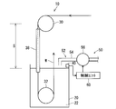
- FIG. 5 is a schematic diagram showing the wire softening device 10.
- the softening device 10 includes a cooling liquid storage unit 20, a first energization sheave 30, a second energization sheave 32, a liquid surface position detection unit 40, and a heating path length control unit 50.
- the coolant reservoir 20 is formed in a container shape that opens upward, and the coolant 22 is stored inside.
- the first energization sheave 30 and the second energization sheave 32 are ring-shaped members around which the wire W can be wound, and the second energization sheave 122 is provided in the coolant reservoir 20, and the first energization sheave 30. Is provided outside the coolant reservoir 20 and vertically above the second energization sheave 122.
- the second energizing sheave 122 is disposed at an upper position sufficiently away from the liquid surface of the cooling liquid 22 in consideration of the distance necessary for heating and softening the wire W.
- a heating power source is connected to the first energizing sheave 30 and the second energizing sheave 32, and the wire W is energized between the first energizing sheave 30 and the second energizing sheave 32.
- the voltage can be applied.
- a cylindrical member 38 is provided so as to cover the wire W passing between the first energizing sheave 30 and the second energizing sheave 32.
- the lower end portion of the cylindrical member 38 is immersed in the coolant 22.
- the cylinder member 38 is constantly supplied with nitrogen, and the space inside the cylinder member 38 is always filled with nitrogen. This nitrogen plays a role of suppressing oxidation of the wire W during heating.
- the wire W is energized and heated between the first energizing sheave 30 and the second energizing sheave 32 and is softened. Moreover, the wire W heated in this way is cooled by being immersed in the cooling liquid 22, and is wound up after that.
- the softening device 10 includes a liquid surface position detection unit 40 and a heating path length control unit 50 in order to suppress variations in the heating path length S of the wire W.
- the liquid level position detection unit 40 is configured to be able to detect the liquid level position of the cooling liquid 22 in the cooling liquid storage unit 20.
- the liquid surface position detection unit 40 may be an optical or ultrasonic sensor that utilizes a reflection phenomenon on the liquid surface, or that conductivity is obtained by immersing the electrode in the liquid. It may be an electrode-type detection unit that is used, or may detect the liquid surface position based on the position of a floater floating on the liquid surface.
- the heating path length control unit 50 controls the heating path length control unit 50 of the wire W between the first energization sheave 30 and the second energization sheave 32 based on the detection result of the liquid surface position detection unit 40. Is configured to do.
- the wire W is energized between the first energization sheave 30 and the second energization sheave 32, the temperature is sufficiently lowered in the portion immersed in the coolant 22. For this reason, it is considered that the wire W is softened by heating between the first energization sheave 30 and the liquid surface of the coolant 22.
- the heating path length S with respect to the wire W is determined by the distance between the first energization sheave 30 and the liquid level of the coolant 22. Therefore, in order to suppress variations in the heating path length S, the liquid level position is set. Adjustment may be made so as to maintain the constant range, or the position of the first energization sheave 30 may be adjusted.
- the heating path length control unit 50 includes a liquid level adjustment unit 52 and a control unit 60.
- the liquid level adjustment unit 52 is configured to be able to adjust the liquid level position of the cooling liquid 22 in the cooling liquid storage unit 20 based on the detection result of the liquid level position detection unit 40.
- the liquid level adjustment unit 52 includes a water supply pipe 54 connected to a coolant supply source (tank or the like) (not shown), and a water supply pump 56 provided in the middle of the water supply pipe 54.
- the water supply port of the water supply pipe 54 is provided at a position where the coolant 22 can be supplied into the coolant reservoir 20.
- the coolant 22 can be supplied into the coolant reservoir 20 by driving the feed pump 56.
- an electromagnetic valve or the like may be used instead of the water supply pump 56.
- the liquid level adjustment unit 52 is configured to be able to adjust the liquid level position of the cooling liquid 22 in the cooling liquid storage unit 20 by supplying the cooling liquid 22 to the cooling liquid storage unit 20. Has been.
- the liquid level adjustment unit 52 may include a drain pipe for draining the coolant 22 in the coolant reservoir 20 and an electromagnetic valve provided in the drain pipe. Thereby, when the coolant 22 is excessively supplied into the coolant reservoir 20, the coolant 22 can be drained. However, during the feeding of the wire W, the cooling liquid 22 is usually only reduced by evaporation or the attachment of the cooling liquid 112 to the wire W. Therefore, there is no such drainage configuration. No problem.
- the configuration may be such that the volume of the coolant reservoir 20 is changed by sinking another object in the coolant reservoir 20.
- control unit 60 Based on the detection result of the liquid level position detection unit 40, the control unit 60 performs an adjustment operation by the liquid level adjustment unit 52 so as to maintain the liquid level position of the cooling liquid in the cooling liquid storage unit 20 within a certain range. Control.
- control unit 60 includes a microprocessor, a main storage unit coupled to the microprocessor, and an auxiliary storage unit.
- the main storage unit is configured by a RAM (Random Access Memory) or the like
- the auxiliary storage unit is configured by a non-temporary storage device such as a flash memory, an EPROM (Erasable Programmable ROM), or a hard disk device.
- the auxiliary storage unit stores a program describing instructions for the microcomputer, and the microprocessor controls the adjustment operation by the liquid level adjustment unit 52 by reading the program and executing each processing step described later. To do.
- FIG. 6 is a flowchart showing processing executed by the control unit 60.
- step S1 the position of the liquid level is acquired through the liquid level position detection unit 40.
- step S2 it is determined whether or not the liquid level position is lower than the first reference position.
- the first reference position is a value preset by an operator or the like and is stored in the auxiliary storage unit of the control unit 60.
- the first reference position is a value set in accordance with an appropriate heat softening condition range (the range of the heating path length S) in order to obtain a target breaking load, and preferably the upper limit of the range of the heating path length S
- the position is set according to the value.
- the heat softening condition range (the range of the heating path length S) itself is determined experimentally and empirically according to the required breaking load and the like. If it is determined as YES in step S2, the process proceeds to step S3. If it is determined as NO, the process proceeds to step S4. If the liquid level position is the same as the first reference position, the process may proceed to either step S3 or S4.
- step S3 the control unit 60 gives an ON command to the water supply pump 56.
- the feed pump 56 starts the operation of sending the coolant 22, the coolant 22 is supplied to the coolant reservoir 20, and the liquid level position of the coolant 22 in the coolant reservoir 20 rises. Then, it returns to step S1.
- step S4 it is determined whether or not the liquid level position is higher than the second reference position.
- the second reference position is also a value set in advance by an operator or the like, and is stored in the auxiliary storage unit of the control unit 60.
- the second reference position is a value set in accordance with an appropriate heat softening condition range (the range of the heating path length S) in order to obtain a target breaking load, and preferably the lower limit of the range of the heating path length S The position is set according to the value.
- the second reference position may be the same as the first reference position.
- step S4 if YES is determined, the process proceeds to step S5. If NO is determined, the process returns to step S1. If the liquid level position is the same as the second reference position, the process may proceed to either step S4 or S5.
- step S5 an off command is given to the water supply pump 56. Thereby, the operation in which the feed water pump 56 sends the coolant 22 is stopped. Then, it returns to step S1.
- the liquid surface position of the coolant 22 in the coolant reservoir 20 is maintained between the first reference position and the second reference position.
- control unit 60 may be realized by hardware. That is, the control unit 60 may be configured to be able to control the operation of the liquid level adjustment unit 52 according to the detection result of the liquid level position detection unit 40.
- a liquid level position detection unit that outputs an on signal (or an off signal) in a normal state and outputs an off signal (or an on signal) when the liquid level position falls below a predetermined value is used.
- the operation of the water supply pump 56 may be controlled based on a signal corresponding to the off signal (or on signal) from the liquid level position detection unit.
- the liquid level position of the coolant 22 in the coolant reservoir 20 is between the first reference position and the second reference position. Kept. Thereby, the distance between the first energizing sheave 30 and the liquid surface of the coolant 22, that is, the heating path length S of the wire W between the first energizing sheave 30 and the second energizing sheave 32 is within a certain range. Maintained.
- variation in the heating path length S with respect to the wire W can be suppressed, and the dispersion
- FIG. 7 is a schematic diagram showing a wire softening device 10B.
- the softening device 10B includes a cooling liquid storage unit 20, a first energization sheave 30, a second energization sheave 32, a liquid surface position detection unit 40, and a heating path length control unit 50B.
- the coolant storing unit 20, the first energizing sheave 30 and the second energizing sheave 32, and the liquid level position detecting unit 40 are the same as those described in the first embodiment.
- the heating path length control unit 50B includes a sheave position adjustment unit 70 that adjusts the position of the first energization sheave 30 with respect to the second energization sheave 32 and a control unit 60B.
- the sheave position adjusting unit 70 is configured by a linear motor or the like whose position can be controlled on a straight line, and is disposed above the first energization sheave 30.
- the second energization sheave 32 can be supported above the first energization sheave 30 so as to be vertically movable and position adjustable.
- the control unit 60B Based on the detection result of the liquid surface position detection unit 40, the control unit 60B maintains the distance between the first energization sheave 30 and the liquid surface of the cooling liquid 22 in the cooling liquid storage unit 20 within a certain range.
- the position adjustment operation of the first energization sheave 30 by the sheave position adjustment unit 70 is controlled.
- control unit 60B is realized by a configuration including a microprocessor, a main storage unit coupled to the microprocessor, and an auxiliary storage unit.
- FIG. 8 is a flowchart showing processing executed by the control unit 60B.
- step S11 the position of the liquid level is acquired through the liquid level position detection unit 40.
- the liquid level position is acquired as a continuous or multistage value.
- a command related to the position of the first energization sheave 30 is output to the sheave position adjustment unit 70 in accordance with the acquired position of the liquid level, whereby the first energization sheave 30 is Move to the position according to the command.
- the position command for the sheave position adjusting unit 70 is a command for setting an appropriate heating softening condition range (a range of the heating path length S) in order to obtain a target breaking load.
- Such a position is obtained, for example, as a difference between the appropriate liquid surface position and an acquired liquid surface position, which are set in advance to obtain an appropriate breaking load.
- the first energization sheave 30 moves to a position corresponding to a preferred heating path length S with respect to the liquid level. Then, it returns to step S11.
- the distance between the liquid level of the coolant 22 and the first energization sheave 30 is maintained within a certain range.
- control unit 60B may be realized by hardware. That is, the control unit 60 ⁇ / b> B may be configured to be able to control the operation of the sheave position adjustment unit 70 according to the detection result of the liquid level position detection unit 40.
- the first energization sheave 30 and the liquid surface position of the cooling liquid 22 are constant by moving the first energization sheave 30 according to the fluctuation of the liquid surface position. Maintained in distance range.
- the heating path length S of the wire W between the first energization sheave 30 and the second energization sheave 32 is maintained within a certain range, and the variation in the heating path length S with respect to the wire W is suppressed as described above.
- the breaking load that is, the variation in the crimping strength between the electric wire and the terminal can be suppressed.
Landscapes
- Chemical & Material Sciences (AREA)
- Engineering & Computer Science (AREA)
- Physics & Mathematics (AREA)
- Thermal Sciences (AREA)
- Crystallography & Structural Chemistry (AREA)
- Mechanical Engineering (AREA)
- Materials Engineering (AREA)
- Metallurgy (AREA)
- Organic Chemistry (AREA)
- Heat Treatment Of Strip Materials And Filament Materials (AREA)
- Control Of Heat Treatment Processes (AREA)
Abstract
Description
まず、技術開発の背景について説明する。図1は背景技術に係る線材Wの軟化装置100を示す概略図である。
また、第1通電用シーブ120と第2通電用シーブ122との間で線材Wに与えられる熱量Q[cal]は次のようになる。
また、周囲温度をT1[℃]、軟化温度をT2[℃]、線材Wの比熱をc[cal/g・℃]、線材Wの重量をm[g]とすると、上記熱量Q[cal]は次のようになる。
従って、式1と式2からQ[cal]を求め、これを式3に代入することで、理論上の軟化温度T2[℃]を求めることができる。
上記知見に鑑み本願発明者が創作した線材Wの軟化装置及び線材Wの軟化方法について説明する。
まず、第1実施形態に係る線材Wの軟化装置10について説明する。図5は線材Wの軟化装置10を示す概略図である。この軟化装置10は、冷却液貯留部20と、第1通電用シーブ30と、第2通電用シーブ32と、液面位置検出部40と、加熱経路長制御部50とを備えている。
次に、第2実施形態に係る線材Wの軟化装置10Bについて説明する。なお、説明にあたって、上記第1実施形態で説明したものと同様構成要素については同一符合を付して説明を省略する。図7は線材Wの軟化装置10Bを示す概略図である。この軟化装置10Bは、冷却液貯留部20と、第1通電用シーブ30と、第2通電用シーブ32と、液面位置検出部40と、加熱経路長制御部50Bとを備えている。
なお、上記各実施形態及び各変形例で説明した各構成は、相互に矛盾しない限り適宜組合わせることができる。
Claims (4)
- 冷却液を貯留する冷却液貯留部と、
前記冷却液貯留部外に設けられ、線材を案内しつつ前記線材に電圧を印加するための第1通電用シーブと、
前記冷却液貯留部内に設けられ、前記第1通電用シーブを経て供給される前記線材を案内しつつ前記線材に通電を行うための第2通電用シーブと、
前記冷却液貯留部における前記冷却液の液面位置を検出する液面位置検出部と、
前記液面位置検出部の検出結果に基づいて、前記第1通電用シーブと前記第2通電用シーブとの間における、前記線材の加熱経路長を制御する加熱経路長制御部と、
を備える線材の軟化装置。 - 請求項1記載の線材の軟化装置であって、
前記加熱経路長制御部は、
前記冷却液貯留部内における前記冷却液の液面位置を調整する液面調整部を備え、
前記液面位置検出部の検出結果に基づいて、前記冷却液貯留部内における前記冷却液の液面位置を一定範囲内に維持するように、前記液面調整部による調整動作が制御される、線材の軟化装置。 - 請求項1記載の線材の軟化装置であって、
前記加熱経路長制御部は、
前記第2通電用シーブに対する前記第1通電用シーブの位置を調整するシーブ位置調整部を備え、
前記液面位置検出部の検出結果に基づいて、前記第1通電用シーブと前記冷却液貯留部内における前記冷却液の液面との距離を一定範囲内に維持するように、前記シーブ位置調整部による前記第1通電用シーブの位置調整動作が制御される、線材の軟化装置。 - (a)冷却液貯留部外に設けられた第1通電用シーブから前記冷却液貯留部内に設けられた前記第1通電用シーブに向けて、前記第1通電用シーブと前記第2通電用シーブとの間で前記線材に通電しつつ前記線材を供給するステップと、
(b)前記冷却液貯留部内の冷却水で前記線材を冷却するステップと、
(c)前記冷却液貯留部における前記冷却液の液面位置の変動に基づいて、前記第1通電用シーブと前記第2通電用シーブとの間における、前記線材の加熱経路長を制御するステップと、
を備える線材の軟化方法。
Priority Applications (3)
| Application Number | Priority Date | Filing Date | Title |
|---|---|---|---|
| CN201280052052.2A CN103890203A (zh) | 2011-10-24 | 2012-02-29 | 线材的软化装置及线材的软化方法 |
| DE112012004425.8T DE112012004425T5 (de) | 2011-10-24 | 2012-02-29 | Draht-Weichglühvorrichtungen und Draht-Weichglühverfahren |
| US14/351,418 US20140246414A1 (en) | 2011-10-24 | 2012-02-29 | Wire softening apparatus and wire softening method |
Applications Claiming Priority (2)
| Application Number | Priority Date | Filing Date | Title |
|---|---|---|---|
| JP2011-232513 | 2011-10-24 | ||
| JP2011232513A JP5817431B2 (ja) | 2011-10-24 | 2011-10-24 | 線材の軟化装置及び線材の軟化方法 |
Publications (1)
| Publication Number | Publication Date |
|---|---|
| WO2013061629A1 true WO2013061629A1 (ja) | 2013-05-02 |
Family
ID=48167476
Family Applications (1)
| Application Number | Title | Priority Date | Filing Date |
|---|---|---|---|
| PCT/JP2012/055032 Ceased WO2013061629A1 (ja) | 2011-10-24 | 2012-02-29 | 線材の軟化装置及び線材の軟化方法 |
Country Status (5)
| Country | Link |
|---|---|
| US (1) | US20140246414A1 (ja) |
| JP (1) | JP5817431B2 (ja) |
| CN (1) | CN103890203A (ja) |
| DE (1) | DE112012004425T5 (ja) |
| WO (1) | WO2013061629A1 (ja) |
Families Citing this family (2)
| Publication number | Priority date | Publication date | Assignee | Title |
|---|---|---|---|---|
| JP7302142B2 (ja) * | 2019-01-17 | 2023-07-04 | 住友電工ウインテック株式会社 | 導体軟化処理装置及び導体軟化処理方法 |
| CN116749498A (zh) * | 2023-08-04 | 2023-09-15 | 山东能特异能源科技有限公司 | 中空玻璃间隔条的折弯方法及其加热装置 |
Citations (3)
| Publication number | Priority date | Publication date | Assignee | Title |
|---|---|---|---|---|
| JPS54108712U (ja) * | 1978-01-18 | 1979-07-31 | ||
| JPS60116727A (ja) * | 1983-11-30 | 1985-06-24 | Showa Electric Wire & Cable Co Ltd | 連続焼鈍装置 |
| JP2000265219A (ja) * | 1999-03-16 | 2000-09-26 | Hitachi Cable Ltd | 線材アニール方法及びその装置 |
Family Cites Families (2)
| Publication number | Priority date | Publication date | Assignee | Title |
|---|---|---|---|---|
| US2176582A (en) * | 1937-11-23 | 1939-10-17 | Cornish Wire Company | Apparatus for annealing moving wire |
| US2176583A (en) * | 1938-07-12 | 1939-10-17 | Cornish Wire Company | Annealing apparatus |
-
2011
- 2011-10-24 JP JP2011232513A patent/JP5817431B2/ja not_active Expired - Fee Related
-
2012
- 2012-02-29 CN CN201280052052.2A patent/CN103890203A/zh active Pending
- 2012-02-29 DE DE112012004425.8T patent/DE112012004425T5/de not_active Withdrawn
- 2012-02-29 WO PCT/JP2012/055032 patent/WO2013061629A1/ja not_active Ceased
- 2012-02-29 US US14/351,418 patent/US20140246414A1/en not_active Abandoned
Patent Citations (3)
| Publication number | Priority date | Publication date | Assignee | Title |
|---|---|---|---|---|
| JPS54108712U (ja) * | 1978-01-18 | 1979-07-31 | ||
| JPS60116727A (ja) * | 1983-11-30 | 1985-06-24 | Showa Electric Wire & Cable Co Ltd | 連続焼鈍装置 |
| JP2000265219A (ja) * | 1999-03-16 | 2000-09-26 | Hitachi Cable Ltd | 線材アニール方法及びその装置 |
Also Published As
| Publication number | Publication date |
|---|---|
| US20140246414A1 (en) | 2014-09-04 |
| CN103890203A (zh) | 2014-06-25 |
| JP5817431B2 (ja) | 2015-11-18 |
| JP2013087360A (ja) | 2013-05-13 |
| DE112012004425T5 (de) | 2014-08-21 |
Similar Documents
| Publication | Publication Date | Title |
|---|---|---|
| JP5817431B2 (ja) | 線材の軟化装置及び線材の軟化方法 | |
| KR200469810Y1 (ko) | 거품을 자동으로 제거할 수 있는 식품 조리 장치 | |
| KR101909735B1 (ko) | 수평 현수제어를 이용한 압출 케이블 냉각 시스템 | |
| US20140271235A1 (en) | Dynamic speed control for pump motor | |
| CN109960209B (zh) | 一种基于力矩极限的电动床智能运行方法及装置 | |
| JP5576342B2 (ja) | ガラスロッドの製造装置および製造方法 | |
| EP2428496B1 (en) | Apparatus for fabricating a glass rod and method of same | |
| JP2015111501A (ja) | 絶縁被覆電線の製造方法及び製造装置 | |
| CN103741170B (zh) | 一种制备稀土金属打弧电解一体炉 | |
| CN109687665A (zh) | 潜油泵电机定子浸漆方法 | |
| KR101330294B1 (ko) | 전기로 투입전압의 제어장치 및 제어방법 | |
| CN204224670U (zh) | 一种铜线感应式连续退火装置 | |
| CN108823373B (zh) | 一种绞合铜导体在线退火装置 | |
| KR101858950B1 (ko) | 유압 비례 밸브와 plc를 이용한 래티스 붐 오프쇼어 크레인의 레벨 포지셔닝 방법 | |
| CN106743894B (zh) | 一种开卷机的张力控制方法 | |
| CN204034980U (zh) | 一种上胶量定量控制装置 | |
| JP2016022467A (ja) | 水素含有液体生成装置及び水素含有液体生成方法 | |
| JP2013189685A (ja) | 線材軟化装置 | |
| CN103899344B (zh) | 一种液压支架顶梁自适应调平方法及装置 | |
| CN210638273U (zh) | 一种客车上水设备地下井电加热器 | |
| NO20190653A1 (en) | An electrode boiler | |
| CN211624323U (zh) | 稳流阀 | |
| CN220723983U (zh) | 一种玻璃纤维丝用浸润装置 | |
| CN211515587U (zh) | 一种电缆拉丝设备 | |
| CN102109458A (zh) | 一种铝合金c环试样升降式间浸应力腐蚀试验装置 |
Legal Events
| Date | Code | Title | Description |
|---|---|---|---|
| 121 | Ep: the epo has been informed by wipo that ep was designated in this application |
Ref document number: 12843323 Country of ref document: EP Kind code of ref document: A1 |
|
| WWE | Wipo information: entry into national phase |
Ref document number: 14351418 Country of ref document: US |
|
| WWE | Wipo information: entry into national phase |
Ref document number: 112012004425 Country of ref document: DE Ref document number: 1120120044258 Country of ref document: DE |
|
| 122 | Ep: pct application non-entry in european phase |
Ref document number: 12843323 Country of ref document: EP Kind code of ref document: A1 |