WO2013054683A1 - 無線通信システム、無線基地局装置、ユーザ端末及び無線通信方法 - Google Patents
無線通信システム、無線基地局装置、ユーザ端末及び無線通信方法 Download PDFInfo
- Publication number
- WO2013054683A1 WO2013054683A1 PCT/JP2012/075395 JP2012075395W WO2013054683A1 WO 2013054683 A1 WO2013054683 A1 WO 2013054683A1 JP 2012075395 W JP2012075395 W JP 2012075395W WO 2013054683 A1 WO2013054683 A1 WO 2013054683A1
- Authority
- WO
- WIPO (PCT)
- Prior art keywords
- base station
- transmission
- user terminal
- radio base
- cell
- Prior art date
Links
Images


Classifications
-
- H—ELECTRICITY
- H04—ELECTRIC COMMUNICATION TECHNIQUE
- H04W—WIRELESS COMMUNICATION NETWORKS
- H04W24/00—Supervisory, monitoring or testing arrangements
- H04W24/08—Testing, supervising or monitoring using real traffic
-
- H—ELECTRICITY
- H04—ELECTRIC COMMUNICATION TECHNIQUE
- H04B—TRANSMISSION
- H04B7/00—Radio transmission systems, i.e. using radiation field
- H04B7/02—Diversity systems; Multi-antenna system, i.e. transmission or reception using multiple antennas
- H04B7/022—Site diversity; Macro-diversity
- H04B7/024—Co-operative use of antennas of several sites, e.g. in co-ordinated multipoint or co-operative multiple-input multiple-output [MIMO] systems
-
- H—ELECTRICITY
- H04—ELECTRIC COMMUNICATION TECHNIQUE
- H04B—TRANSMISSION
- H04B7/00—Radio transmission systems, i.e. using radiation field
- H04B7/02—Diversity systems; Multi-antenna system, i.e. transmission or reception using multiple antennas
- H04B7/04—Diversity systems; Multi-antenna system, i.e. transmission or reception using multiple antennas using two or more spaced independent antennas
- H04B7/06—Diversity systems; Multi-antenna system, i.e. transmission or reception using multiple antennas using two or more spaced independent antennas at the transmitting station
- H04B7/0613—Diversity systems; Multi-antenna system, i.e. transmission or reception using multiple antennas using two or more spaced independent antennas at the transmitting station using simultaneous transmission
- H04B7/0615—Diversity systems; Multi-antenna system, i.e. transmission or reception using multiple antennas using two or more spaced independent antennas at the transmitting station using simultaneous transmission of weighted versions of same signal
- H04B7/0619—Diversity systems; Multi-antenna system, i.e. transmission or reception using multiple antennas using two or more spaced independent antennas at the transmitting station using simultaneous transmission of weighted versions of same signal using feedback from receiving side
- H04B7/0621—Feedback content
- H04B7/0632—Channel quality parameters, e.g. channel quality indicator [CQI]
-
- H—ELECTRICITY
- H04—ELECTRIC COMMUNICATION TECHNIQUE
- H04B—TRANSMISSION
- H04B7/00—Radio transmission systems, i.e. using radiation field
- H04B7/02—Diversity systems; Multi-antenna system, i.e. transmission or reception using multiple antennas
- H04B7/04—Diversity systems; Multi-antenna system, i.e. transmission or reception using multiple antennas using two or more spaced independent antennas
- H04B7/06—Diversity systems; Multi-antenna system, i.e. transmission or reception using multiple antennas using two or more spaced independent antennas at the transmitting station
- H04B7/0613—Diversity systems; Multi-antenna system, i.e. transmission or reception using multiple antennas using two or more spaced independent antennas at the transmitting station using simultaneous transmission
- H04B7/0615—Diversity systems; Multi-antenna system, i.e. transmission or reception using multiple antennas using two or more spaced independent antennas at the transmitting station using simultaneous transmission of weighted versions of same signal
- H04B7/0619—Diversity systems; Multi-antenna system, i.e. transmission or reception using multiple antennas using two or more spaced independent antennas at the transmitting station using simultaneous transmission of weighted versions of same signal using feedback from receiving side
- H04B7/0636—Feedback format
- H04B7/0639—Using selective indices, e.g. of a codebook, e.g. pre-distortion matrix index [PMI] or for beam selection
-
- H—ELECTRICITY
- H04—ELECTRIC COMMUNICATION TECHNIQUE
- H04J—MULTIPLEX COMMUNICATION
- H04J11/00—Orthogonal multiplex systems, e.g. using WALSH codes
- H04J11/0023—Interference mitigation or co-ordination
- H04J11/005—Interference mitigation or co-ordination of intercell interference
- H04J11/0053—Interference mitigation or co-ordination of intercell interference using co-ordinated multipoint transmission/reception
-
- H—ELECTRICITY
- H04—ELECTRIC COMMUNICATION TECHNIQUE
- H04W—WIRELESS COMMUNICATION NETWORKS
- H04W72/00—Local resource management
- H04W72/50—Allocation or scheduling criteria for wireless resources
- H04W72/54—Allocation or scheduling criteria for wireless resources based on quality criteria
Definitions
- the present invention relates to a radio communication system, a radio base station apparatus, a user terminal, and a radio communication method applicable to a cellular system or the like.
- Non-patent Document 1 In the UMTS (Universal Mobile Telecommunications System) network, WSDPA (High Speed Downlink Packet Access) and HSUPA (High Speed Uplink Packet Access) are adopted for the purpose of improving frequency utilization efficiency and data rate.
- the system features based on CDMA (Wideband-Code Division Multiple Access) are being extracted to the maximum.
- LTE Long Term Evolution
- Non-patent Document 1 LTE (Long Term Evolution) has been studied for the purpose of further high data rate and low delay.
- the third generation system can achieve a maximum transmission rate of about 2 Mbps on the downlink using generally a fixed bandwidth of 5 MHz.
- a maximum transmission rate of about 300 Mbps on the downlink and about 75 Mbps on the uplink can be realized using a variable band of 1.4 MHz to 20 MHz.
- LTE-A LTE Advanced
- inter-cell orthogonalization is one promising technique for further improving the system performance over the LTE system.
- orthogonalization within a cell is realized by orthogonal multi-access for both uplink and downlink. That is, in the downlink, orthogonalization is performed between user terminals UE (User Equipment) in the frequency domain.
- UE User Equipment
- W-CDMA Wideband Code Division Multiple Access
- a coordinated multi-point transmission / reception (CoMP) technique is being studied as a technique for realizing inter-cell orthogonalization.
- CoMP coordinated multi-point transmission / reception
- a plurality of cells perform transmission / reception signal processing in cooperation with one or a plurality of user terminals UE.
- simultaneous transmission of multiple cells to which precoding is applied, cooperative scheduling / beamforming, and the like are being studied.
- Application of these CoMP transmission / reception techniques is expected to improve the throughput characteristics of the user terminal UE located particularly at the cell edge.
- Downlink CoMP transmission / reception includes Coordinated Scheduling / Coordinated Beamforming and Joint processing.
- Joint processing Joint transmission that transmits a shared data channel from a plurality of cells to one user terminal UE, and Dynamic Point Selection (hereinafter referred to as “ DPS ”).
- DPS Dynamic Point Selection
- DPS Dynamic Point Selection
- the present invention has been made in view of such points, and a radio communication system and a radio base station capable of effectively estimating Cooperative cells that cause interference at the time of CoMP transmission in a radio base station apparatus and effectively performing CoMP transmission
- An object is to provide an apparatus, a user terminal, and a wireless communication method.
- a radio communication system of the present invention is a radio communication system comprising a plurality of radio base station devices and a user terminal configured to be capable of cooperative multipoint transmission / reception with the plurality of radio base station devices, wherein the user terminal Has a transmitter that transmits information used to estimate a candidate cell that becomes an interference cell in coordinated multipoint transmission, and the radio base station apparatus performs interference in coordinated multipoint transmission based on the information. It has the estimation part which estimates the candidate cell used as a cell, It is characterized by the above-mentioned.
- a radio base station apparatus is a radio base station apparatus in a radio communication system comprising a plurality of radio base station apparatuses and a user terminal configured to be capable of cooperative multipoint transmission / reception with the plurality of radio base station apparatuses.
- the said radio base station apparatus has an estimation part which estimates the candidate cell used as an interference cell in the case of cooperative multipoint transmission based on the information transmitted from the said user terminal, It is characterized by the above-mentioned.
- a user terminal is a user terminal in a radio communication system comprising a plurality of radio base station devices and a user terminal configured to be capable of cooperative multipoint transmission / reception with the plurality of radio base station devices,
- the user terminal includes a transmission unit that transmits information used to estimate a candidate cell that becomes an interference cell in cooperative multipoint transmission.
- a radio communication method of the present invention is a radio communication method of a radio communication system comprising a plurality of radio base station devices and a user terminal configured to be capable of cooperative multipoint transmission / reception with the plurality of radio base station devices.
- a step of transmitting information used for estimation of a candidate cell that becomes an interference cell at the time of cooperative multipoint transmission, and at the time of cooperative multipoint transmission based on the information in the radio base station device And a step of estimating a candidate cell to be an interference cell.
- Downlink CoMP transmission includes Coordinated Scheduling / Coordinated Beamforming and Joint processing.
- Coordinated Scheduling / Coordinated Beamforming is a method of transmitting a shared data channel only from one cell to one user terminal UE, and considers interference from other cells and interference to other cells as shown in FIG. 1A. Then, radio resources are allocated in the frequency / space region.
- Joint processing is a method of transmitting a shared data channel from a plurality of cells simultaneously by applying precoding. As shown in FIG. 1B, a shared data channel is transmitted from a plurality of cells to one user terminal UE. There are Joint transmission for transmission and Dynamic Point Selection (DPS) for instantly selecting one cell and transmitting a shared data channel as shown in FIG. 1C.
- DPS Dynamic Point Selection
- a plurality of remote radio devices (RRE: Remote Radio Equipment) connected to a radio base station device (radio base station device eNB) by an optical fiber or the like. ) (Centralized control based on the RRE configuration) and a configuration of the radio base station device (radio base station device eNB) (autonomous distributed control based on the independent base station configuration) as shown in FIG. 2B.
- RRE Remote Radio Equipment
- FIG. 2A shows a configuration including a plurality of remote radio apparatuses RRE, it may be configured to include only a single remote radio apparatus RRE as shown in FIG.
- the remote radio apparatuses RRE1 and RRE2 are centrally controlled by the radio base station apparatus eNB.
- an optical fiber is used between a radio base station apparatus eNB (concentrated base station) that performs baseband signal processing and control of a plurality of remote radio apparatuses RRE and each cell (that is, each remote radio apparatus RRE). Since connection is performed using a baseband signal, radio resource control between cells can be performed collectively in a centralized base station. That is, the problem of signaling delay and overhead between radio base station apparatuses eNB, which is a problem in the independent base station configuration, is small, and high-speed radio resource control between cells is relatively easy. Therefore, in the RRE configuration, a method using high-speed signal processing between cells such as simultaneous transmission of a plurality of cells can be applied in the downlink.
- radio resource allocation control such as scheduling is performed in each of the plurality of radio base station apparatuses eNB (or RRE).
- the radio resource allocation information such as timing information and scheduling is transmitted to any one of the radio base stations as necessary in the X2 interface between the radio base station apparatus eNB of the cell 1 and the radio base station apparatus eNB of the cell 2. It transmits to apparatus eNB and performs cooperation between cells.
- a cell that transmits a shared data channel is instantaneously selected based on channel quality information (CQI: Channel Quality Indicator) generated by the user terminal UE.
- CQI Channel Quality Indicator
- the reception SINR Signal to Interference and Noise Ratio
- FIG. 3 is a schematic diagram for explaining a cell configuration of the radio communication system.
- the radio base station apparatus eNB in the serving cell notifies the user terminal UE of a measurement candidate cell (RRM measurement set) 110 by a control signal of an RRC (Radio Resource Control) protocol.
- RRM measurement set a measurement candidate cell
- RRC Radio Resource Control
- the user terminal UE is based on CRS (Cell Specific Reference Signal) or CSI-RS (Channel State Information Reference Signal) received from each measurement candidate cell 110, RSRP (Reference Signal Received Power) / RSRQ (Reference Signal Received Quality). Measure. And user terminal UE judges whether CoMP transmission (DPS) should be requested from a measurement result of RSRP / RSRQ. For example, whether or not the RSRP / RSRQ of the neighboring cell exceeds the RSRP / RSRQ of the serving cell or whether the RSRP / RSRQ of the serving cell falls below the threshold It is done by whether or not.
- CRS Cell Specific Reference Signal
- CSI-RS Channel State Information Reference Signal
- the measurement report (measurement report) result is sent to the radio base station apparatus eNB as a higher layer signaling (for example, it reports by RRC signaling) and requests CoMP transmission (DPS).
- the content of the measurement report result transmitted from the user terminal UE to the radio base station apparatus eNB includes RSRP / RSRQ of the serving cell and RERP / RSRQ of the neighboring cells.
- the radio base station apparatus eNB designates a channel quality measurement cell (CoMP measurement set) 111 from the measurement candidate cells 110 based on the measurement report result. Then, the radio base station apparatus eNB sends a connection reconfiguration signal (RRC Connection Reconfiguration) including notification of the channel quality measurement cell (CoMP measurement set) 111 to the user terminal UE to which CoMP transmission (DPS) should be applied. Send.
- RRC Connection Reconfiguration a connection reconfiguration signal including notification of the channel quality measurement cell (CoMP measurement set) 111 to the user terminal UE to which CoMP transmission (DPS) should be applied.
- connection reconfiguration complete (RRC Connection Reconfiguration Complete) for notifying that the notification of the channel quality measurement cell 111 has been received. It transmits with respect to the wireless base station apparatus eNB.
- the user terminal UE determines a shared data channel non-transmission candidate cell that gives strong interference from the channel quality measurement cells 111 notified from the radio base station apparatus eNB, and sets the shared data channel from the cell to be empty.
- the CQI in the case of transmission is fed back to the radio base station apparatus eNB by PUCCH (Physical Uplink Control Channel).
- PUCCH Physical Uplink Control Channel
- the radio base station apparatus eNB determines a CoMP transmission transmission cell (CoMP transmission points) from the channel quality measurement cells based on the CQI fed back from the user terminal UE.
- the user terminal UE determines a shared data channel non-transmission candidate cell that gives strong interference from the channel quality measurement cells 111 notified from the radio base station apparatus eNB.
- the CQI when the shared data channel from the cell is not transmitted is fed back to the radio base station apparatus eNB.
- the radio base station apparatus eNB since the user terminal UE cannot estimate which cell in the channel quality measurement cell 111 is determined as a shared data channel non-transmission candidate cell and feedback CQI, the radio base station apparatus eNB side Therefore, there is a problem that it is not possible to appropriately estimate the cooperative cell that causes interference.
- the present inventors pay attention to this point, and in the case where CoMP transmission (DPS) is applied, by enabling the radio base station apparatus eNB to estimate the shared data channel non-transmission candidate cell, the cooperative cell that causes interference And the present invention has been completed.
- DPS CoMP transmission
- the gist of the present invention is that when CoMP transmission (DPS) is applied, the radio base station apparatus eNB appropriately estimates a cooperative cell that causes interference at the time of CoMP transmission based on information from the user terminal UE. Effective CoMP transmission.
- DPS CoMP transmission
- the information from the user terminal UE used when the radio base station apparatus eNB estimates the shared data channel non-transmission candidate cell is as follows: Cell information (shared data channel non-transmission candidate cell information) and a measurement report result are included.
- Cell information shared data channel non-transmission candidate cell information
- a measurement report result are included.
- the radio base station apparatus eNB performs signaling to the user terminal UE (method 2).
- the shared data channel non-transmission candidate cell when the information from the user terminal UE is shared data channel non-transmission candidate cell information, the shared data channel non-transmission candidate cell from the user terminal UE to the radio base station apparatus eNB by higher layer signaling using the measurement report result Method of signaling information (method 1-1) and method of dynamically signaling shared data channel non-transmission candidate cell information from user terminal UE to radio base station apparatus eNB using feedback of channel quality information (CQI) 1-2).
- Method of signaling information method 1-1
- CQI channel quality information
- the radio base station device eNB estimates the shared data channel non-transmission candidate cell from the measurement report result sent from the user terminal UE, and this sharing Data channel non-transmission candidate cell information is signaled to the user terminal UE. Examples of this signaling include higher layer signaling and dynamic signaling using PDCCH.
- the radio base station apparatus eNB estimates a shared data channel non-transmission candidate cell using the shared data channel non-transmission candidate cell information signaled from the user terminal UE to the radio base station apparatus eNB.
- the shared data channel non-transmission candidate cell information from the user terminal UE is signaled by higher layer signaling using the measurement report result (method 1-1), or dynamically signaled using CQI feedback. (Method 1-2).
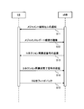
- FIG. 4 is a sequence diagram of CoMP transmission (DPS).
- the radio base station apparatus eNB in the serving cell notifies the user terminal UE of the measurement candidate cell 110 using the RRC protocol control signal (S11).
- User terminal UE measures RSRP / RSRQ based on CRS or CSI-RS received from each measurement candidate cell 110. Then, the user terminal UE determines whether or not to request CoMP transmission (DPS) based on the RSRP / RSRQ measurement result, and estimates a shared data channel non-transmission candidate cell that is expected to give strong interference. To do.
- the shared data channel non-transmission candidate cell is estimated based on, for example, whether the RSRP / RSRQ of the cell exceeds the RSRP / RSRQ of the serving cell, or whether the RSRP / RSRQ of the cell exceeds the threshold. .
- the shared data channel non-transmission candidate cell information together with the measurement report result to the radio base station apparatus eNB Is reported by higher layer signaling (for example, RRC signaling) (S12).
- higher layer signaling for example, RRC signaling
- the radio base station apparatus eNB designates the channel quality measurement cell 111 from the measurement candidate cells 110 based on the measurement report result and the shared data channel non-transmission candidate cell information. At this time, the radio base station apparatus eNB considers the shared data non-transmission candidate cell information from the user terminal UE, for example, specifies the channel quality measurement cell 111 so as not to include the shared data channel non-transmission candidate cell. . Then, the radio base station apparatus eNB transmits a connection reconfiguration signal including the notification of the channel quality measurement cell 111 to the user terminal UE to which CoMP transmission (DPS) should be applied (S13).
- DPS CoMP transmission
- the user terminal UE In response to the connection reconfiguration signal from the radio base station apparatus eNB, the user terminal UE sends a connection reconfiguration completion signal for notifying that the notification of the channel quality measurement cell 111 has been received to the radio base station apparatus eNB. It transmits to (S14).
- the user terminal UE determines a shared data channel non-transmission candidate cell that gives strong interference from the channel quality measurement cells 111 notified from the radio base station apparatus eNB, and sets the shared data channel from the cell to be empty.
- the CQI in the case of transmission is fed back to the radio base station apparatus eNB by PUCCH (S15).
- the radio base station apparatus eNB determines the CoMP transmission transmission cell 112 from the channel quality measurement cells 111 based on the CQI fed back from the user terminal UE.
- the radio base station apparatus eNB uses the information from the user terminal UE. Based on this, it is possible to estimate the shared data channel non-transmission candidate cell that gives strong interference at the stage of specifying the channel quality measurement cell 111. Therefore, it is possible to appropriately estimate the cooperative cell that causes interference during CoMP transmission (DPS) and effectively perform CoMP transmission.
- DPS CoMP transmission
- FIG. 5 is a schematic diagram showing a cell configuration of a channel quality measurement cell in CoMP transmission (DPS).
- cell 1 is a serving cell
- cells 2 and 3 are neighboring cells.
- the radio base station apparatus eNB in the serving cell notifies the user terminal UE of the measurement candidate cell 110 using the RRC protocol control signal (S11).
- User terminal UE measures RSRP / RSRQ based on CRS or CSI-RS received from each measurement candidate cell 110.
- the measurement report result is sent to the radio base station apparatus eNB as a higher layer signaling (for example, , RRC signaling) (S12).
- the radio base station apparatus eNB designates the channel quality measurement cell 111 from among the measurement candidate cells 110 based on the measurement report result. Then, the radio base station apparatus eNB transmits a connection reconfiguration signal including the notification of the channel quality measurement cell 111 to the user terminal UE to which CoMP transmission (DPS) should be applied (S13).
- DPS CoMP transmission
- the user terminal UE In response to the connection reconfiguration signal from the radio base station apparatus eNB, the user terminal UE sends a connection reconfiguration completion signal for notifying that the notification of the channel quality measurement cell 111 has been received to the radio base station apparatus eNB. It transmits to (S14).
- the user terminal UE measures the CQI in the channel quality measurement cell 111 notified from the radio base station apparatus eNB, and determines a shared data channel non-transmission candidate cell that gives strong interference. Then, CQI when the shared data channel non-transmission candidate cell is not transmitted is fed back to the radio base station apparatus eNB using PUCCH (S15), and the shared data channel non-transmission candidate cell information is changed to PUCCH. To the radio base station apparatus eNB.
- the user terminal UE when measuring the CQI of the cell 1 shown in FIG. 5, the user terminal UE measures the following four patterns of CQI: (1) When the shared data channel from the cells 2 and 3 is transmitted (2 When the shared data channel from cell 2 is not transmitted, (3) When the shared data channel from cell 3 is not transmitted, (4) When the shared data channel from cells 2 and 3 is not transmitted . Similarly, the user terminal UE measures four patterns of CQIs for the cells 2 and 3. Then, the user terminal UE determines the CQI with the highest communication quality among all measured CQIs, that is, the CQI when the shared data channel from the shared data channel non-transmission candidate cell that gives strong interference is not transmitted. To do.
- the CQI in (2) is the CQI with the highest communication quality
- it can be determined that the shared data channel non-transmission candidate cell that gives strong interference is the cell 2 when the cell 1 is the serving cell.
- the user terminal UE feeds back the CQI in (2) above (CQI when the cell 1 is used as a serving cell and the shared data channel from the cell 2 is not transmitted) to the radio base station apparatus eNB, and is shared.
- Cell information (for example, bitmap information) indicating the cell 2 which is a data channel non-transmission candidate cell is signaled to the radio base station apparatus eNB.
- the radio base station apparatus eNB transmits a shared data channel from the channel quality measurement cell 111 to the user terminal UE based on the CQI fed back from the user terminal UE and the shared data channel non-transmission candidate cell information. Cell 112 is determined.
- the radio base station apparatus eNB is based on information from the user terminal UE.
- the shared data channel non-transmission candidate cell can be determined with high accuracy. Therefore, it is possible to appropriately estimate the cooperative cell that causes interference during CoMP transmission (DPS) and effectively perform CoMP transmission.
- DPS CoMP transmission
- the radio base station apparatus eNB that is a transmission destination for signaling the shared data channel non-transmission candidate cell from the user terminal UE may be a normal macro base station or a low transmission power base station (for example, Phantom cell). It may be. Further, the low transmission power base station (for example, Phantom cell) notified of the shared data channel non-transmission candidate cell from the user terminal UE notifies the macro base station of the notified shared data channel non-transmission candidate cell. May be.
- Method 2 the radio base station apparatus eNB estimates the shared data channel non-transmission candidate cell from the measurement report result sent from the user terminal UE to the radio base station apparatus eNB, and the shared data channel non-transmission candidate cell information is obtained by the user. Signal to terminal UE.
- a method for determining the CoMP transmission transmission cell 112 in this case will be described with reference to FIGS.
- the radio base station apparatus eNB in the serving cell notifies the user terminal UE of the measurement candidate cell 110 using the RRC protocol control signal (S11).
- User terminal UE measures RSRP / RSRQ based on CRS or CSI-RS received from each measurement candidate cell 110.
- the measurement report result is sent to the radio base station apparatus eNB as a higher layer signaling (for example, , RRC signaling) (S12).
- the radio base station apparatus eNB designates the channel quality measurement cell 111 from the measurement candidate cells 110 based on the measurement report result (RSRP / RSRQ), and estimates the shared data channel non-transmission candidate cell. Then, the radio base station apparatus eNB transmits a connection reconfiguration signal including the notification of the channel quality measurement cell 111 to the user terminal UE to which CoMP transmission (DPS) should be applied (S13), and the shared data channel Signal non-transmission candidate cell information to the user terminal UE.
- DPS CoMP transmission
- a method for estimating a shared data channel non-transmission candidate cell in the radio base station apparatus eNB will be described with reference to FIG. From the measurement report result from the user terminal UE, when the reception level (RSRP / RSRQ) in each cell is cell 1 (serving cell)> cell 2> cell 3, the radio base station apparatus eNB indicates that the cell 2 is shared data. It is estimated that this is a channel non-transmission candidate cell.
- the radio base station apparatus eNB signals the user terminal UE to feed back the CQI when the cell 2 is a shared data channel non-transmission candidate cell.
- the shared data channel non-transmission candidate cell information is signaled semi-statically by higher layer signaling (for example, RRC signaling) or dynamically signaled using PDCCH.
- the user terminal UE In response to the connection reconfiguration signal from the radio base station apparatus eNB, the user terminal UE sends a connection reconfiguration completion signal for notifying that the notification of the channel quality measurement cell 111 has been received to the radio base station apparatus eNB. It transmits to (S14).
- the user terminal UE measures the CQI in the channel quality measurement cell 111 notified from the radio base station apparatus eNB. At this time, the user terminal UE measures CQI when the shared data channel non-transmission candidate cell designated by the radio base station apparatus eNB is not transmitted. Then, the user terminal UE feeds back the measured CQI to the radio base station apparatus eNB using PUCCH (S15).
- the radio base station apparatus eNB determines the CoMP transmission transmission cell 112 that transmits the shared data channel to the user terminal UE from the channel quality measurement cells 111 based on the CQI fed back from the user terminal UE.
- the radio base station apparatus eNB estimates the shared data channel non-transmission candidate cell from the measurement report result sent from the user terminal UE, and signals this shared data channel non-transmission candidate cell information to the user terminal UE Since the overhead of CQI fed back from the user terminal UE can be reduced, the amount of signals can be reduced. In addition, since the radio base station apparatus eNB estimates the shared data channel non-transmission candidate cell from the measurement report result sent from the user terminal UE, it appropriately estimates the cooperative cell that causes interference during CoMP transmission (DPS), CoMP transmission can be effectively performed.
- DPS CoMP transmission
- the normal macro base station may notify the user terminal UE of the shared data channel non-transmission candidate cell.
- the shared data channel non-transmission candidate cell may be notified from the low transmission power base station (for example, Phantom cell) to the user terminal UE.
- the macro base station to the low transmission power base station (for example, Phantom cell) in advance.
- the shared data channel non-transmission candidate cell may be notified.
- FIG. 6 is an explanatory diagram of a system configuration of the wireless communication system according to the present embodiment.
- the radio communication system shown in FIG. 6 is a system that includes, for example, the LTE system or SUPER 3G.
- carrier aggregation in which a plurality of fundamental frequency blocks with the system band of the LTE system as a unit is integrated is used.
- this wireless communication system may be called IMT-Advanced or 4G.
- the radio communication system 1 includes radio base station devices 20A and 20B and a plurality of first and second user terminals 10A and 10B communicating with the radio base station devices 20A and 20B. It is configured.
- the radio base station devices 20 ⁇ / b> A and 20 ⁇ / b> B are connected to the higher station device 30, and the higher station device 30 is connected to the core network 40.
- the radio base station apparatuses 20A and 20B are connected to each other by wired connection or wireless connection.
- the first and second user terminals 10A and 10B can communicate with the radio base station apparatuses 20A and 20B in the cells 1 and 2, respectively.
- the upper station device 30 includes, for example, an access gateway device, a radio network controller (RNC), a mobility management entity (MME), and the like, but is not limited thereto.
- RNC radio network controller
- MME mobility management entity
- the first and second user terminals 10A and 10B include an LTE terminal and an LTE-A terminal.
- the description will proceed as the first and second user terminals 10A and 10B unless otherwise specified.
- the radio base station apparatuses 20A and 20B and the first and second user terminals 10A and 10B which are mobile terminal apparatuses, will be described as wirelessly communicating.
- the first and second user terminals 10A and 10B 10B may be a user device including a fixed terminal device more generally.
- OFDMA Orthogonal Frequency Division Multiple Access
- SC-FDMA Single Carrier-Frequency Division Multiple Access
- OFDMA is a multi-carrier transmission scheme that performs communication by dividing a frequency band into a plurality of narrow frequency bands (subcarriers) and mapping data to each subcarrier.
- SC-FDMA is a single carrier transmission method that reduces interference between terminals by dividing a system band into bands each consisting of one or continuous resource blocks for each terminal, and a plurality of terminals using different bands. .
- the downlink communication channel includes PDSCH (Physical Downlink Shared Channel) as a downlink data channel shared by the first and second user terminals 10A and 10B, and a downlink L1 / L2 control channel (PDCCH, PCFICH, PHICH) Have Transmission data and higher control information are transmitted by the PDSCH.
- PDSCH and PUSCH scheduling information and the like are transmitted by PDCCH (Physical Downlink Control Channel).
- the number of OFDM symbols used for PDCCH is transmitted by PCFICH (Physical Control Format Indicator Channel).
- the HARQ ACK / NACK for PUSCH is transmitted by PHICH (Physical Hybrid-ARQ Indicator Channel).
- the uplink communication channel includes a PUSCH as an uplink data channel shared by the user terminals 10A and 10B and a PUCCH that is an uplink control channel. Transmission data and higher control information are transmitted by this PUSCH. Also, downlink radio quality information (CQI: Channel Quality Indicator), ACK / NACK, etc. are transmitted by PUCCH.
- CQI Channel Quality Indicator
- ACK / NACK etc. are transmitted by PUCCH.
- the overall configuration of the radio base station apparatus will be described with reference to FIG. Note that the radio base station apparatuses 20A and 20B have the same configuration and will be described as the radio base station apparatus 20. Also, the first and second user terminals 10A and 10B have the same configuration and will be described as the user terminal 10.
- the radio base station apparatus 20 includes transmission / reception antennas 201a and 201b, amplifier units 202a and 202b, transmission / reception units 203a and 203b, a baseband signal processing unit 204, a call processing unit 205, and a transmission path interface 206. Yes. Transmission data transmitted from the radio base station apparatus 20 to the user terminal 10 via the downlink is input from the higher station apparatus 30 to the baseband signal processing unit 204 via the transmission path interface 206.
- the downlink data channel signal is transmitted from the RCP layer, such as PDCP layer processing, transmission data division / combination, RLC (Radio Link Control) retransmission control transmission processing, and MAC (Medium Access).
- RCP layer such as PDCP layer processing, transmission data division / combination, RLC (Radio Link Control) retransmission control transmission processing, and MAC (Medium Access).
- Control Retransmission control, for example, HARQ transmission processing, scheduling, transmission format selection, channel coding, inverse fast Fourier transform (IFFT) processing, and precoding processing are performed.
- transmission processing such as channel coding and inverse fast Fourier transform is performed on the signal of the physical downlink control channel that is the downlink control channel.
- the baseband signal processing unit 204 notifies the control information for each user terminal 10 to wirelessly communicate with the radio base station apparatus 20 to the user terminals 10 connected to the same cell through the broadcast channel.
- the information for communication in the cell includes, for example, system bandwidth in uplink or downlink, and root sequence identification information (Root Sequence) for generating a random access preamble signal in PRACH (Physical Random Access Channel). Index) etc. are included.
- the transmission / reception units 203a and 203b convert the baseband signal output from the baseband signal processing unit 204 into a radio frequency band.
- the amplifier units 202a and 202b amplify the frequency-converted radio frequency signal and output it to the transmission / reception antennas 201a and 201b.
- the radio frequency signal received by the transmission / reception antenna 201 is amplified by the amplifier units 202a and 202b, and the frequency conversion is performed by the transmission / reception units 203a and 203b. And converted into a baseband signal and input to the baseband signal processing unit 204.
- the baseband signal processing unit 204 performs FFT processing, IDFT processing, error correction decoding, MAC retransmission control reception processing, RLC layer, PDCP layer reception processing on transmission data included in the baseband signal received in the uplink I do.
- the decoded signal is transferred to the higher station apparatus 30 via the transmission path interface 206.
- the call processing unit 205 performs call processing such as communication channel setting and release, state management of the radio base station apparatus 20, and radio resource management.
- the user terminal 10 includes a transmission / reception antenna 101, an amplifier unit 102, a transmission / reception unit 103, a baseband signal processing unit 104, and an application unit 105.
- a radio frequency signal received by the transmission / reception antenna 101 is amplified by the amplifier unit 102, frequency-converted by the transmission / reception unit 103, and converted into a baseband signal.
- the baseband signal is subjected to FFT processing, error correction decoding, retransmission control reception processing, and the like by the baseband signal processing unit 104.
- downlink transmission data is transferred to the application unit 105.
- the application unit 105 performs processing related to layers higher than the physical layer and the MAC layer. Also, the broadcast information in the downlink data is also transferred to the application unit 105.
- uplink transmission data is input from the application unit 105 to the baseband signal processing unit 104.
- the baseband signal processing unit 104 performs mapping processing, retransmission control (HARQ) transmission processing, channel coding, DFT processing, and IFFT processing.
- the transmission / reception unit 103 converts the baseband signal output from the baseband signal processing unit 104 into a radio frequency band. Thereafter, the amplifier unit 102 amplifies the frequency-converted radio frequency signal and transmits it from the transmission / reception antenna 101.
- HARQ retransmission control
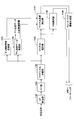
- the radio base station apparatus shown in FIG. 9 has a centralized control type radio base station configuration.
- radio resource allocation control such as scheduling is collectively performed in a certain radio base station apparatus (central radio base station apparatus, cell 1 in FIG. 9), and the subordinate radio base station apparatus (remote radio apparatus, FIG. 9).
- Cell 2 follows the radio resource allocation result of the radio base station apparatus.
- feedback information CQI is used as information necessary for radio resource allocation between a plurality of cells in the user scheduling control unit 921 of the radio base station apparatus.
- each functional block in FIG. 9 mainly relates to the processing contents of the baseband processing unit 204 shown in FIG. Further, the functional block diagram of FIG. 9 is simplified for explaining the present invention, and is assumed to have a configuration normally provided in the baseband processing unit 204.
- the transmission unit on the concentrated radio base station apparatus (cell 1) side includes a downlink control information generation unit 901, a downlink control information encoding / modulation unit 902, a downlink reference signal generation unit 903, a downlink transmission data generation unit 904, An upper control information generation unit 905 and a downlink transmission data encoding / modulation unit 906 are provided.
- the transmission unit on the central radio base station apparatus (cell 1) side includes a mapping unit 907, a precoding multiplication unit 908, a precoding weight generation unit 909, a downlink channel multiplexing unit 910, and an IFFT unit 911 (911a, 911a, 911b), CP adding section 912 (912a, 912b), transmission amplifier 913 (913a, 913b), transmission antenna 914 (914a, 914b), control channel signal demodulation section 920, and user scheduling control section 921 I have.
- the transmission amplifier 913 and the transmission antenna 914 correspond to the amplifier unit 202 and the transmission / reception antenna 201 shown in FIG. 7, respectively.
- the transmission unit on the remote radio apparatus (cell 2) side of the subordinate cell includes a downlink control information generation unit 931, a downlink control information encoding / modulation unit 932, a downlink reference signal generation unit 933, and a downlink transmission data generation unit. 934, and a downlink transmission data encoding / modulating unit 936.
- the transmission unit on the remote radio apparatus (cell 2) side of the subordinate cell includes a mapping unit 937, a precoding multiplication unit 938, a precoding weight generation unit 939, a downlink channel multiplexing unit 940, and IFFT units 941a and 941b.
- CP adding units 942a and 942b transmission amplifiers 943a and 943b, and transmission antennas 944a and 944b.
- the centralized radio base station device and the remote radio device of the subordinate cell are connected by, for example, an optical fiber.
- the downlink control information generation units 901 and 931 generate downlink control information under the control of the user scheduling control unit 921 and output the downlink control information to the downlink control information encoding / modulation units 902 and 932, respectively.
- Downlink control information coding / modulation sections 902 and 932 perform channel coding and data modulation on the downlink control information, and output them to mapping sections 907 and 937, respectively.
- the downlink reference signal generators 903 and 933 generate downlink reference signals (CRS, CSI-RS, DM-RS) and output the downlink reference signals to the mapping units 907 and 937, respectively.
- Downlink transmission data generation sections 904 and 934 generate downlink transmission data, and output the downlink transmission data to downlink transmission data encoding / modulation sections 906 and 936, respectively.
- the higher control information generation section 905 generates higher control information transmitted / received by higher layer signaling (for example, RRC signaling), and outputs the generated higher control information to the downlink transmission data encoding / modulation section 906.
- the higher control information generation unit 905 generates higher control information including notification of measurement candidate cells, channel quality measurement cells, CoMP transmission transmission cells, and the like to the user terminal 10.
- the downlink transmission data encoding / modulation section 906 performs channel encoding and data modulation on the downlink transmission data and higher control information, and outputs the result to the mapping section 907.
- the downlink transmission data encoding / modulation section 936 performs channel encoding and data modulation on the downlink transmission data, and outputs the result to the mapping section 937.
- the mapping units 907 and 937 map the downlink control information, the downlink reference signal, the downlink transmission data, and the upper control information, and output them to the precoding multipliers 908 and 938, respectively.
- the precoding weight generation units 909 and 939 generate precoding weights based on the PMI fed back from the user terminal 10 and output the precoding weights to the precoding multiplication units 908 and 938, respectively.
- each of the precoding weight generation units 909 and 939 includes a codebook, and selects a precoding weight corresponding to PMI from the codebook.
- the PMI used in precoding weight generation sections 909 and 939 is provided from control channel signal demodulation section 920.
- the precoding multipliers 908 and 938 multiply the transmission signal by the precoding weight. That is, the precoding multipliers 908 and 938 perform phase shift and / or amplitude shift for each of the transmission antennas 914a and 914b and the transmission antennas 944a and 944b based on the precoding weights given from the precoding weight generation units 909 and 939. Do. Precoding multiplication sections 908 and 938 output the phase-shifted and / or amplitude-shifted transmission signals to downlink channel multiplexing sections 910 and 940, respectively.
- the downlink channel multiplexers 910 and 940 combine the downlink control information, the downlink reference signal, the higher-level control information, and the downlink transmission data that have been phase-shifted and / or amplitude-shifted, for each of the transmission antennas 914a and 914b and the transmission antennas 944a and 944b.
- a transmission signal is generated.
- Downlink channel multiplexing sections 910 and 940 output this transmission signal to IFFT (Inverse Fast Fourier Transform) sections 911a and 911b and IFFT sections 941a and 941b, respectively.
- IFFT Inverse Fast Fourier Transform
- IFFT sections 911a and 911b and IFFT sections 941a and 941b perform IFFT on the transmission signal and output the transmission signal after IFFT to CP adding sections 912a and 912b and CP adding sections 942a and 942b.
- CP adding sections 912a and 912b and CP adding sections 942a and 942b add CP (Cyclic Prefix) to the transmission signal after IFFT, and transmit the transmission signal after CP addition to transmission amplifiers 913a and 913b and transmission amplifiers 943a and 943b. Output each.
- the transmission amplifiers 913a and 913b and the transmission amplifiers 943a and 943b amplify the transmission signal after CP addition.
- the amplified transmission signals are transmitted to the user terminal 10 on the downlink from the transmission antennas 914a and 914b and the transmission antennas 944a and 944b, respectively.
- the control channel signal demodulator 920 demodulates the control channel signal notified from the user terminal 10 via the PUCCH, outputs the PMI included in the control channel signal to the precoding weight generators 909 and 939, and performs user scheduling control on the CQI.
- uplink transmission data demodulation unit (not shown) demodulates uplink transmission data and outputs CQI included in the uplink transmission data to user scheduling control unit 921.
- the user scheduling control unit 921 is notified of the measurement report result (RSRP / RSRQ) from the upper layer. Further, the user scheduling control unit 921 determines a CoMP transmission transmission cell that transmits a shared data channel to the user terminal 10 and a cooperative cell that stops data transmission when CoMP transmission (DPS) is applied, based on the CQI.
- RSRP / RSRQ measurement report result
- DPS CoMP transmission
- upper control information generation section 905 When Method 1 is applied, first, upper control information generation section 905 generates higher control information including notification of measurement candidate cells to user terminal 10.
- the measurement report result (RSRP / RSRQ) from the user terminal 10 is notified to the user scheduling control unit 921 from the upper layer.
- the shared data channel non-transmission candidate cell information is notified to the user scheduling control unit 921 together with the measurement report result.
- the upper control information generation section 905 Based on the measurement report result, the upper control information generation section 905 generates an upper control signal including notification of the channel quality measurement cell to the user terminal 10.
- the CQI from the user terminal 10 is demodulated by the control channel signal demodulator 920 and notified to the user scheduling controller 921.
- shared data channel non-transmission candidate cell information is notified to user scheduling control section 921 together with CQI.
- the upper control information generation section 905 Based on the CQI fed back from the user terminal 10, the upper control information generation section 905 generates an upper control signal including a notification of the CoMP transmission transmission cell to the user terminal 10.
- the upper control information generation section 905 When Method 2 is applied, first, the upper control information generation section 905 generates higher control information including notification of measurement candidate cells to the user terminal 10.
- the measurement report result (RSRP / RSRQ) from the user terminal 10 is notified to the user scheduling control unit 921 from the upper layer.
- Upper control information generation section 905 estimates a shared data channel non-transmission candidate cell based on the measurement report result.
- the upper control information generation section 905 Based on the measurement report result, the upper control information generation section 905 generates an upper control signal including notification of the channel quality measurement cell to the user terminal 10.
- the CQI from the user terminal 10 is demodulated by the control channel signal demodulator 920 and notified to the user scheduling controller 921.
- the upper control information generation section 905 Based on the CQI fed back from the user terminal 10, the upper control information generation section 905 generates an upper control signal including a notification of the CoMP transmission transmission cell to the user terminal 10.
- the radio base station apparatus shown in FIG. 10 has an autonomous distributed control type radio base station configuration.
- radio resource allocation control such as scheduling is performed in each of a plurality of radio base station apparatuses.
- feedback information CQI is used as information necessary for radio resource allocation or the like in user scheduling control units 921 and 951 in a plurality of radio base station apparatuses.
- each functional block in FIG. 10 mainly relates to the processing contents of the baseband processing unit 204 shown in FIG. Further, the functional block diagram of FIG. 10 is simplified for explaining the present invention, and is assumed to have a configuration normally provided in the baseband processing unit 204.
- the same functional blocks as those in FIG. 9 are denoted by the same reference numerals as those in FIG.
- the transmission unit on the cell 1 side includes a downlink control information generation unit 901, a downlink control information encoding / modulation unit 902, a downlink reference signal generation unit 903, a downlink transmission data generation unit 904, and an upper control information generation unit 905.
- the transmission unit on the cell 2 side also includes a downlink control information generation unit 931, a downlink control information encoding / modulation unit 932, a downlink reference signal generation unit 933, a downlink transmission data generation unit 934, and higher control information generation.
- Unit 935 downlink transmission data encoding / modulation unit 936, mapping unit 937, precoding multiplication unit 938, precoding weight generation unit 939, downlink channel multiplexing unit 940, IFFT units 941a and 941b, and CP Additional units 942a and 942b, transmission amplifiers 943a and 943b, transmission antennas 944a and 944b, a control channel signal demodulation unit 950, a user scheduling control unit 951, and an inter-cell control information transmission / reception unit 952 are provided.
- the functions of the higher control information generating section 935, the control channel signal demodulating section 950, and the user scheduling control section 951 included in the cell 2 side transmission section are the upper control information generating section 905 and control channel included in the cell 1 side transmission section, respectively.
- the functions of the signal demodulator 920 and the user scheduling controller 921 are the same.
- the higher control information generation section 935 generates higher control information that is transmitted and received by higher layer signaling (for example, RRC signaling), and outputs the generated higher control information to the downlink transmission data encoding / modulation section 936.
- the downlink transmission data coding / modulation section 936 performs channel coding and data modulation on the downlink transmission data and higher control information, and outputs the result to the mapping section 937.
- Control channel signal demodulation section 950 also demodulates the control channel signal notified from user terminal 10 via PUCCH, outputs PMI included in the control channel signal to precoding weight generation section 939, and controls CQI for user scheduling. Output to the unit 951.
- the uplink data channel demodulation unit (not shown) demodulates the uplink transmission data, and outputs the CQI included in the uplink transmission data to the user scheduling control unit 951.
- the user scheduling control unit 951 performs scheduling control of downlink control information in the target cell based on the CQI.
- the inter-cell control information transmission / reception units 922 and 952 are connected by an X2 interface, and transmit / receive timing information and scheduling information output from the user scheduling control units 921 and 951 to / from each other. Thereby, the cooperation between cells is attained.
- Each functional block in FIG. 11 mainly relates to the processing contents of the baseband signal processing unit 104 shown in FIG. Further, the functional blocks shown in FIG. 11 are simplified for the purpose of explaining the present invention, and the configuration normally provided in the baseband processing unit is provided.
- the receiving unit of the user terminal includes a CP removing unit 1101, an FFT unit 1102, a downlink channel separating unit 1103, a downlink control information receiving unit 1104, a downlink transmission data receiving unit 1105, a channel estimating unit 1106, and a channel quality measurement.
- the channel quality measurement unit 1107 functions as a channel state information generation unit.
- the transmission signal transmitted from the radio base station apparatus eNB is received by the transmission / reception antenna 101 illustrated in FIG. 8 and output to the CP removal unit 1101.
- CP removing section 1101 removes the CP from the received signal and outputs it to FFT section 1102.
- the FFT unit 1102 performs fast Fourier transform (FFT) on the signal after CP removal, and converts the signal in the time domain into a signal in the frequency domain.
- FFT section 1102 outputs the signal converted to the frequency domain signal to downlink channel separation section 1103.
- the downlink channel separator 1103 separates the downlink channel signal into downlink control information, downlink transmission data, higher control information, and downlink reference signals.
- Downlink channel separator 1103 outputs downlink control information to downlink control information receiver 1104, outputs downlink transmission data and higher control information to downlink transmission data receiver 1105, and outputs a downlink reference signal to channel estimator 1106. .
- the downlink control information receiving unit 1104 demodulates the downlink control information and outputs the demodulated control information to the downlink transmission data receiving unit 1105. Further, the downlink control information receiving section 1104 demodulates a control channel signal (for example, PDCCH) included in the downlink control information. Downlink transmission data receiving section 1105 demodulates downlink transmission data using the control information. Also, downlink transmission data reception section 1105 demodulates higher control information included in downlink transmission data and notifies channel quality measurement section 1107 of it.
- Channel estimation section 1106 estimates the channel state using the downlink reference signal, and outputs the estimated channel state to channel quality measurement section 1107 and PMI selection section 1108.
- the channel quality measurement unit 1107 measures RSRP / RSRQ and CQI from the channel state notified from the channel estimation unit 1106 based on the upper control information notified from the downlink transmission data reception unit 1105.
- the RSRP / RSRQ and CQI measured by the channel quality measurement unit 1107 are output to the feedback information generation unit 1109 as feedback information.
- the PMI selection unit 1108 selects a PMI from the channel state notified from the channel estimation unit 1106 using a code book.
- the PMI selected by the PMI selection unit 1108 is output to the feedback information generation unit 1109 as feedback information.
- the feedback information generation unit 1109 feeds back the RSRP / RSRQ and CQI measured by the channel quality measurement unit 1107 to the radio base station apparatus 20 as feedback information.
- channel quality measurement section 1107 measures RSRP / RSRQ in each cell of the measurement candidate cells notified as a higher control signal from radio base station apparatus 20, and provides feedback information generation section 1109 with it. Output.
- feedback information generation section 1109 estimates a shared data channel non-transmission candidate cell that is expected to give strong interference.
- the feedback information generation unit 1109 feeds back the measurement report result and the shared data channel non-transmission candidate cell information to the radio base station apparatus 20 as feedback information.
- the user terminal 10 measures the CQI in the channel quality measurement cell notified as higher control information from the radio base station apparatus 20 in the channel quality measurement unit 1107, and outputs the measured CQI to the feedback information generation unit 1109. .
- Feedback information generation section 1109 determines the CQI with the highest communication quality, and the CQI is fed back to radio base station apparatus 20 as feedback information.
- the feedback information generation unit 1109 feeds back the measurement report result to the radio base station apparatus 20 as feedback information.
- the user terminal 10 measures the CQI in the channel quality measurement cell notified as higher control information from the radio base station apparatus 20 in the channel quality measurement unit 1107, and the shared data channel non-transmission candidate cell information together with the measured CQI. Is output to the feedback information generation unit 1109.
- Feedback information generation section 1109 determines the CQI with the highest communication quality, and feeds back the CQI and shared data channel non-transmission candidate cell information to radio base station apparatus 20 as feedback information.
- the channel quality measurement unit 1107 measures RSRP / RSRQ in each measurement candidate cell notified from the radio base station apparatus 20 as an upper control signal, and sends it to the feedback information generation unit 1109. Output.
- the feedback information generation unit 1109 feeds back the measurement report result to the radio base station apparatus 20 as feedback information.
- the user terminal 10 measures the CQI in the channel quality measurement cell notified from the radio base station apparatus 20 by the higher control signal in the channel quality measurement unit 1107.
- the CQI is measured with the shared data channel non-transmission candidate cell notified by the higher control signal or the control channel signal being not transmitted, and the measured CQI is output to the feedback information generating section 1109.
- the feedback information generation unit 1109 feeds back the CQI to the radio base station apparatus 20 as feedback information.
- this invention is not limited to description of a specification, A various change can be implemented.
- the feedback information from the user terminal UE is illustrated as an aspect of signaling using CQI.
- the shared data channel non-transmission candidate cell can be specified in the radio base station apparatus eNB, other information May be used.
- the ratio (S 1 / S 2 ) between the signal reception component (S 1 ) from the cell 1 serving as the serving cell and the signal reception component (S 2 ) from the cell 2 serving as the cooperative cell can be used.
- the connection relationships and functions of the components shown in this specification can be changed as appropriate.
- the structures described in this specification can be implemented in appropriate combination.
- the present invention can be implemented with appropriate modifications without departing from the scope of the present invention.
Landscapes
- Engineering & Computer Science (AREA)
- Computer Networks & Wireless Communication (AREA)
- Signal Processing (AREA)
- Physics & Mathematics (AREA)
- Mathematical Physics (AREA)
- Mobile Radio Communication Systems (AREA)
Abstract
無線基地局装置においてCoMP送信時に干渉となる協調セルを適切に推定して、効果的にCoMP送信すること。本発明の無線通信システムは、複数の無線基地局装置と、複数の無線基地局装置と協調マルチポイント送受信可能に構成されたユーザ端末(UE)と、を備え、ユーザ端末(UE)は、協調マルチポイント送信の際に干渉セルとなる候補セルの推定に使用する情報を送信する送信部を有し、無線基地局装置は、当該情報に基づいて協調マルチポイント送信の際に干渉セルとなる候補セルを推定する推定部を有する。
Description
本発明は、セルラーシステム等に適用可能な無線通信システム、無線基地局装置、ユーザ端末及び無線通信方法に関する。
UMTS(Universal Mobile Telecommunications System)ネットワークにおいては、周波数利用効率の向上、データレートの向上を目的として、HSDPA(High Speed Downlink Packet Access)やHSUPA(High Speed Uplink Packet Access)を採用することにより、W-CDMA(Wideband‐Code Division Multiple Access)をベースとしたシステムの特徴を最大限に引き出すことが行われている。このUMTSネットワークについては、更なる高速データレート、低遅延などを目的としてLTE(Long Term Evolution)が検討されている(非特許文献1)。
第3世代のシステムは、概して5MHzの固定帯域を用いて、下り回線で最大2Mbps程度の伝送レートを実現できる。一方、LTEのシステムでは、1.4MHz~20MHzの可変帯域を用いて、下り回線で最大300Mbps及び上り回線で75Mbps程度の伝送レートを実現できる。また、UMTSネットワークにおいては、更なる広帯域化及び高速化を目的として、LTEの後継のシステムも検討されている(例えば、LTEアドバンスト(LTE-A))。
3GPP, TR25.912 (V7.1.0), "Feasibility study for Evolved UTRA and UTRAN", Sept. 2006
ところで、LTEシステムに対してさらにシステム性能を向上させるための有望な技術の1つとして、セル間直交化がある。例えば、LTE-Aシステムでは、上下リンクとも直交マルチアクセスによりセル内の直交化が実現されている。すなわち、下りリンクでは、周波数領域においてユーザ端末UE(User Equipment)間で直交化されている。一方、セル間はW-CDMAと同様、1セル周波数繰り返しによる干渉ランダム化が基本である。
そこで、3GPP(3rd Generation Partnership Project)では、セル間直交化を実現するための技術として、協調マルチポイント送受信(CoMP:Coordinated Multi-Point transmission/reception)技術が検討されている。このCoMP送受信では、1つあるいは複数のユーザ端末UEに対して複数のセルが協調して送受信の信号処理を行う。例えば、下りリンクでは、プリコーディングを適用する複数セル同時送信、協調スケジューリング/ビームフォーミングなどが検討されている。これらのCoMP送受信技術の適用により、特にセル端に位置するユーザ端末UEのスループット特性の改善が期待される。
下りリンクのCoMP送受信には、Coordinated Scheduling/Coordinated Beamformingと、Joint processingとがある。また、Joint processingには、1つのユーザ端末UEに対して複数のセルから共有データチャネルを送信するJoint transmissionと、瞬時に1つのセルを選択し共有データチャネルを送信するDynamic Point Selection(以下、「DPS」という)とがある。CoMP送信(DPS)が適用される場合においては、干渉となる協調セルのデータ送信を停止することから、効率的にCoMP送信(DPS)の制御を行うためには、無線基地局装置でCoMP送信時に干渉となる協調セルを適切に推定することが求められる。
本発明はかかる点に鑑みてなされたものであり、無線基地局装置においてCoMP送信時に干渉となる協調セルを適切に推定して、効果的にCoMP送信することができる無線通信システム、無線基地局装置、ユーザ端末及び無線通信方法を提供することを目的とする。
本発明の無線通信システムは、複数の無線基地局装置と、前記複数の無線基地局装置と協調マルチポイント送受信可能に構成されたユーザ端末と、を備えた無線通信システムであって、前記ユーザ端末は、協調マルチポイント送信の際に干渉セルとなる候補セルの推定に使用する情報を送信する送信部を有し、前記無線基地局装置は、前記情報に基づいて協調マルチポイント送信の際に干渉セルとなる候補セルを推定する推定部を有することを特徴とする。
本発明の無線基地局装置は、複数の無線基地局装置と、前記複数の無線基地局装置と協調マルチポイント送受信可能に構成されたユーザ端末と、を備えた無線通信システムにおける無線基地局装置であって、前記無線基地局装置は、前記ユーザ端末から送信される情報に基づいて協調マルチポイント送信の際に干渉セルとなる候補セルを推定する推定部を有することを特徴とする。
本発明のユーザ端末は、複数の無線基地局装置と、前記複数の無線基地局装置と協調マルチポイント送受信可能に構成されたユーザ端末と、を備えた無線通信システムにおけるユーザ端末であって、前記ユーザ端末は、協調マルチポイント送信の際に干渉セルとなる候補セルの推定に使用する情報を送信する送信部を有することを特徴とする。
本発明の無線通信方法は、複数の無線基地局装置と、前記複数の無線基地局装置と協調マルチポイント送受信可能に構成されたユーザ端末と、を備えた無線通信システムの無線通信方法であって、前記ユーザ端末において、協調マルチポイント送信の際に干渉セルとなる候補セルの推定に使用する情報を送信する工程と、前記無線基地局装置において、前記情報に基づいて協調マルチポイント送信の際に干渉セルとなる候補セルを推定する工程と、を有することを特徴とする。
本発明によれば、無線基地局装置においてCoMP送信時に干渉となる協調セルを適切に推定して、効果的にCoMP送信することができる。
以下、本発明の実施の形態について、添付図面を参照して詳細に説明する。
まず、図1を用いて下りリンクのCoMP送信について説明する。下りリンクのCoMP送信としては、Coordinated Scheduling/Coordinated Beamformingと、Joint processingとがある。Coordinated Scheduling/Coordinated Beamformingは、1つのユーザ端末UEに対して1つのセルからのみ共有データチャネルを送信する方法であり、図1Aに示すように、他セルからの干渉や他セルへの干渉を考慮して周波数/空間領域における無線リソースの割り当てを行う。一方、Joint processingは、プリコーディングを適用して複数のセルから同時に共有データチャネルを送信する方法であり、図1Bに示すように、1つのユーザ端末UEに対して複数のセルから共有データチャネルを送信するJoint transmissionと、図1Cに示すように、瞬時に1つのセルを選択し共有データチャネルを送信するDynamic Point Selection(DPS)とがある。
CoMP送受信を実現する構成としては、例えば、図2Aに示すように、無線基地局装置(無線基地局装置eNB)に対して光ファイバ等で接続された複数の遠隔無線装置(RRE:Remote Radio Equipment)とを含む構成(RRE構成に基づく集中制御)と、図2Bに示すように、無線基地局装置(無線基地局装置eNB)の構成(独立基地局構成に基づく自律分散制御)とがある。なお、図2Aにおいては、複数の遠隔無線装置RREを含む構成を示すが、図1に示すように、単一の遠隔無線装置RREのみを含む構成としてもよい。
図2Aに示す構成(RRE構成)においては、遠隔無線装置RRE1,RRE2を無線基地局装置eNBで集中的に制御する。RRE構成では、複数の遠隔無線装置RREのベースバンド信号処理及び制御を行う無線基地局装置eNB(集中基地局)と各セル(すなわち、各遠隔無線装置RRE)との間が光ファイバを用いたベースバンド信号で接続されるため、セル間の無線リソース制御を集中基地局において一括して行うことができる。すなわち、独立基地局構成で問題となる無線基地局装置eNB間のシグナリングの遅延やオーバヘッドの問題が小さく、セル間の高速な無線リソース制御が比較的容易となる。したがって、RRE構成においては、下りリンクでは、複数セル同時送信のような高速なセル間の信号処理を用いる方法が適用できる。
一方、図2Bに示す構成(独立基地局構成)においては、複数の無線基地局装置eNB(又はRRE)でそれぞれスケジューリングなどの無線リソース割り当て制御を行う。この場合においては、セル1の無線基地局装置eNBとセル2の無線基地局装置eNBとの間のX2インターフェースで必要に応じてタイミング情報やスケジューリングなどの無線リソース割り当て情報をいずれかの無線基地局装置eNBに送信して、セル間の協調を行う。
図1Cに示すCoMP送信(DPS)では、ユーザ端末UEが生成したチャネル品質情報(CQI:Channel Quality Indicator)に基づいて、共有データチャネルを送信するセルが瞬時に選択される。また、選択された送信セルからの信号に対して干渉となる協調セルの無線リソース(resource block)における送信を停止することで、セル境界のユーザ端末UEの受信SINR(Signal to Interference and Noise Ratio)を大きく改善できる。
ここで、CoMP送信(DPS)において、ユーザ端末UEに共有データチャネルを送信するセル(CoMP送信伝達セル)の決定方法について、図3を参照して説明する。図3は、無線通信システムのセル構成を説明するための模式図である。
まず、サービングセルにおける無線基地局装置eNBが、ユーザ端末UEに、メジャメント候補セル(RRM measurement set)110をRRC(Radio Resource Control)プロトコルの制御信号によって通知する。
ユーザ端末UEは、各メジャメント候補セル110から受信したCRS(Cell specific Reference Signal)又はCSI-RS(Channel State Information Reference Signal)に基づいて、RSRP(Reference Signal Received Power)/RSRQ(Reference Signal Received Quality)を測定する。そして、ユーザ端末UEは、RSRP/RSRQの測定結果より、CoMP送信(DPS)を要求すべきか否か判定する。CoMP送信(DPS)を要求すべきか否かの判定は、例えば、周辺セルのRSRP/RSRQが、サービングセルのRSRP/RSRQを上回ったか否か、あるいは、サービングセルのRSRP/RSRQがしきい値を下回ったか否かなどで行う。ユーザ端末UEが、RSRP/RSRQの測定結果より、CoMP送信(DPS)を要求すべきと判定した場合には、無線基地局装置eNBに対してメジャメントレポート(測定報告)結果を、ハイヤレイヤシグナリング(例えば、RRCシグナリング)で報告し、CoMP送信(DPS)を要求する。なお、ユーザ端末UEから無線基地局装置eNBへ送信されるメジャメントレポート結果の内容には、サービングセルのRSRP/RSRQ及び周辺セルのRERP/RSRQが含まれる。
無線基地局装置eNBは、メジャメントレポート結果に基づいて、メジャメント候補セル110の中からチャネル品質測定用セル(CoMP measurement set)111を指定する。そして、無線基地局装置eNBは、チャネル品質測定用セル(CoMP measurement set)111の通知を含むコネクション再構成信号(RRC Connection Reconfiguration)を、CoMP送信(DPS)を適用すべきユーザ端末UEに対して送信する。
ユーザ端末UEは、無線基地局装置eNBからのコネクション再構成信号に対応して、チャネル品質測定用セル111の通知を受信したことを通知するためのコネクション再構成完了信号(RRC Connection Reconfiguration Complete)を無線基地局装置eNBに対して送信する。
その後、ユーザ端末UEは、無線基地局装置eNBから通知されたチャネル品質測定用セル111の中から、強い干渉を与える共有データチャネル無送信候補セルを判定し、当該セルからの共有データチャネルを無送信とした場合のCQIを、PUCCH(Physical Uplink Control Channel)で無線基地局装置eNBへとフィードバックする。
無線基地局装置eNBは、ユーザ端末UEからフィードバックされたCQIに基づいて、チャネル品質測定用セルの中からCoMP送信伝達セル(CoMP transmission points)を決定する。
上述したように、CoMP送信(DPS)では、ユーザ端末UEは、無線基地局装置eNBから通知されたチャネル品質測定用セル111の中から、強い干渉を与える共有データチャネル無送信候補セルを判定し、当該セルからの共有データチャネルを無送信とした場合のCQIを無線基地局装置eNBにフィードバックする。しかしながら、無線基地局装置eNBでは、ユーザ端末UEが、チャネル品質測定用セル111におけるどのセルを共有データチャネル無送信候補セルと判定してCQIをフィードバックしたか推定できないため、無線基地局装置eNB側で干渉となる協調セルを適切に推定できないという問題があった。
本発明者らはこの点に着目し、CoMP送信(DPS)が適用される場合において、無線基地局装置eNBが共有データチャネル無送信候補セルを推定できるようにすることで、干渉となる協調セルを適切に推定可能になることを見出して本発明を完成させた。
すなわち、本発明の骨子は、CoMP送信(DPS)が適用される場合において、無線基地局装置eNBが、ユーザ端末UEからの情報に基づいて、CoMP送信時に干渉となる協調セルを適切に推定して、効果的にCoMP送信することにある。
本発明において、無線基地局装置eNBが共有データチャネル無送信候補セル(CoMP送信の際に干渉セルとなるセル)を推定する際に使用するユーザ端末UEからの情報としては、ユーザ端末UEからのセル情報(共有データチャネル無送信候補セル情報)と、メジャメントレポートの結果とが挙げられる。ユーザ端末UEからの情報が共有データチャネル無送信候補セル情報である場合には、ユーザ端末UEから無線基地局装置eNBにシグナリングし(方法1)、ユーザ端末UEからの情報がメジャメントレポートの結果である場合には、無線基地局装置eNBからユーザ端末UEにシグナリングする(方法2)。
また、ユーザ端末UEからの情報が共有データチャネル無送信候補セル情報である場合には、メジャメントレポート結果を用いてハイヤレイヤシグナリングでユーザ端末UEから無線基地局装置eNBに共有データチャネル無送信候補セル情報をシグナリングする方法(方法1-1)と、チャネル品質情報(CQI)のフィードバックを用いてダイナミックにユーザ端末UEから無線基地局装置eNBに共有データチャネル無送信候補セル情報をシグナリングする方法(方法1-2)とがある。
また、ユーザ端末UEからの情報がメジャメントレポートの結果である場合には、無線基地局装置eNBは、ユーザ端末UEから送られたメジャメントレポート結果から共有データチャネル無送信候補セルを推定し、この共有データチャネル無送信候補セル情報をユーザ端末UEにシグナリングする。このシグナリングとしては、ハイヤレイヤシグナリング、PDCCHを用いたダイナミックなシグナリングが挙げられる。
(方法1)
方法1においては、ユーザ端末UEから無線基地局装置eNBにシグナリングされる共有データチャネル無送信候補セル情報を用いて、無線基地局装置eNBが共有データチャネル無送信候補セルを推定する。この場合、ユーザ端末UEからの共有データチャネル無送信候補セル情報は、メジャメントレポート結果を用いてハイヤレイヤシグナリングでシグナリングされるか(方法1-1)、あるいは、CQIのフィードバックを用いてダイナミックにシグナリングされる(方法1-2)。
方法1においては、ユーザ端末UEから無線基地局装置eNBにシグナリングされる共有データチャネル無送信候補セル情報を用いて、無線基地局装置eNBが共有データチャネル無送信候補セルを推定する。この場合、ユーザ端末UEからの共有データチャネル無送信候補セル情報は、メジャメントレポート結果を用いてハイヤレイヤシグナリングでシグナリングされるか(方法1-1)、あるいは、CQIのフィードバックを用いてダイナミックにシグナリングされる(方法1-2)。
(方法1-1)
ユーザ端末UEが、メジャメントレポート結果を用いてハイヤレイヤシグナリングで共有データチャネル無送信候補セル情報を無線基地局装置eNBにシグナリングする場合のCoMP送信伝達セル112の決定方法について、図3,図4を参照して説明する。図4は、CoMP送信(DPS)のシーケンス図である。
ユーザ端末UEが、メジャメントレポート結果を用いてハイヤレイヤシグナリングで共有データチャネル無送信候補セル情報を無線基地局装置eNBにシグナリングする場合のCoMP送信伝達セル112の決定方法について、図3,図4を参照して説明する。図4は、CoMP送信(DPS)のシーケンス図である。
まず、サービングセルにおける無線基地局装置eNBが、ユーザ端末UEに、メジャメント候補セル110をRRCプロトコルの制御信号によって通知する(S11)。
ユーザ端末UEは、各メジャメント候補セル110から受信したCRS又はCSI-RSに基づいて、RSRP/RSRQを測定する。そして、ユーザ端末UEは、RSRP/RSRQの測定結果に基づいて、CoMP送信(DPS)を要求すべきか否か判定するとともに、強い干渉を与えることが予想される共有データチャネル無送信候補セルを推定する。共有データチャネル無送信候補セルは、例えば、当該セルのRSRP/RSRQがサービングセルのRSRP/RSRQを上回ったか否か、あるいは、当該セルのRSRP/RSRQがしきい値を上回ったか否かなどによって推定する。
ユーザ端末UEが、RSRP/RSRQの測定結果より、CoMP送信(DPS)を要求すべきと判定した場合には、無線基地局装置eNBに対して、メジャメントレポート結果とともに共有データチャネル無送信候補セル情報を、ハイヤレイヤシグナリング(例えば、RRCシグナリング)で報告する(S12)。
無線基地局装置eNBは、メジャメントレポート結果及び共有データチャネル無送信候補セル情報に基づいて、メジャメント候補セル110の中からチャネル品質測定用セル111を指定する。このとき、無線基地局装置eNBは、ユーザ端末UEからの共有データ無送信候補セル情報を考慮して、例えば、共有データチャネル無送信候補セルを含まないようにチャネル品質測定用セル111を指定する。そして、無線基地局装置eNBは、チャネル品質測定用セル111の通知を含むコネクション再構成信号を、CoMP送信(DPS)を適用すべきユーザ端末UEに対して送信する(S13)。
ユーザ端末UEは、無線基地局装置eNBからのコネクション再構成信号に対応して、チャネル品質測定用セル111の通知を受信したことを通知するためのコネクション再構成完了信号を無線基地局装置eNBに対して送信する(S14)。
その後、ユーザ端末UEは、無線基地局装置eNBから通知されたチャネル品質測定用セル111の中から、強い干渉を与える共有データチャネル無送信候補セルを判定し、当該セルからの共有データチャネルを無送信とした場合のCQIを、PUCCHで無線基地局装置eNBへとフィードバックする(S15)。
無線基地局装置eNBは、ユーザ端末UEからフィードバックされたCQIに基づいて、チャネル品質測定用セル111の中からCoMP送信伝達セル112を決定する。
このように、ユーザ端末UEが、メジャメントレポート結果を用いて共有データチャネル無送信候補セル情報を無線基地局装置eNBにシグナリングする場合には、無線基地局装置eNBは、ユーザ端末UEからの情報に基づいて、チャネル品質測定用セル111を指定する段階で、強い干渉を与える共有データチャネル無送信候補セルを推定することができる。したがって、CoMP送信(DPS)時に干渉となる協調セルを適切に推定して、効果的にCoMP送信することが可能となる。
(方法1-2)
一方、ユーザ端末UEが、CQIのフィードバックを用いてダイナミックに共有データチャネル無送信候補セル情報を無線基地局装置eNBにシグナリングする場合のCoMP送信伝達セル112の決定方法について、図3~図5を参照して説明する。図5は、CoMP送信(DPS)におけるチャネル品質測定用セルのセル構成を示す模式図である。図5において、セル1はサービングセルであり、セル2,3は周辺セルである。
一方、ユーザ端末UEが、CQIのフィードバックを用いてダイナミックに共有データチャネル無送信候補セル情報を無線基地局装置eNBにシグナリングする場合のCoMP送信伝達セル112の決定方法について、図3~図5を参照して説明する。図5は、CoMP送信(DPS)におけるチャネル品質測定用セルのセル構成を示す模式図である。図5において、セル1はサービングセルであり、セル2,3は周辺セルである。
まず、サービングセルにおける無線基地局装置eNBが、ユーザ端末UEに、メジャメント候補セル110をRRCプロトコルの制御信号によって通知する(S11)。
ユーザ端末UEは、各メジャメント候補セル110から受信したCRS又はCSI-RSに基づいて、RSRP/RSRQを測定する。そして、ユーザ端末UEが、RSRP/RSRQの測定結果より、CoMP送信(DPS)を要求すべきと判定した場合には、無線基地局装置eNBに対して、メジャメントレポート結果を、ハイヤレイヤシグナリング(例えば、RRCシグナリング)で報告する(S12)。
無線基地局装置eNBは、メジャメントレポート結果に基づいて、メジャメント候補セル110の中からチャネル品質測定用セル111を指定する。そして、無線基地局装置eNBは、チャネル品質測定用セル111の通知を含むコネクション再構成信号を、CoMP送信(DPS)を適用すべきユーザ端末UEに対して送信する(S13)。
ユーザ端末UEは、無線基地局装置eNBからのコネクション再構成信号に対応して、チャネル品質測定用セル111の通知を受信したことを通知するためのコネクション再構成完了信号を無線基地局装置eNBに対して送信する(S14)。
その後、ユーザ端末UEは、無線基地局装置eNBから通知されたチャネル品質測定用セル111におけるCQIを測定し、強い干渉を与える共有データチャネル無送信候補セルを判定する。そして、当該共有データチャネル無送信候補セルを無送信とした場合のCQIを、PUCCHを用いて無線基地局装置eNBへとフィードバックする(S15)とともに、当該共有データチャネル無送信候補セル情報を、PUCCHで無線基地局装置eNBにシグナリングする。
例えば、図5に示すセル1のCQIを測定する場合、ユーザ端末UEは、次の4パターンのCQIを測定する:(1)セル2,3からの共有データチャネルを送信とした場合、(2)セル2からの共有データチャネルを無送信とした場合、(3)セル3からの共有データチャネルを無送信とした場合、(4)セル2,3からの共有データチャネルを無送信とした場合。ユーザ端末UEは、セル2,3についても同様に、それぞれ4パターンのCQIを測定する。そして、ユーザ端末UEは、測定したすべてのCQIの中から、最も通信品質の高いCQI、すなわち強い干渉を与える共有データチャネル無送信候補セルからの共有データチャネルを無送信とした場合のCQIを判定する。例えば、上記(2)におけるCQIが最も通信品質の高いCQIであった場合には、セル1をサービングセルとした場合に、強い干渉を与える共有データチャネル無送信候補セルはセル2であると判定できる。この場合、ユーザ端末UEは、上記(2)におけるCQI(セル1をサービングセルとし、セル2からの共有データチャネルを無送信とした場合のCQI)を無線基地局装置eNBへとフィードバックするとともに、共有データチャネル無送信候補セルであるセル2を示すセル情報(例えば、ビットマップ情報)を無線基地局装置eNBにシグナリングする。
無線基地局装置eNBは、ユーザ端末UEからフィードバックされたCQI及び共有データチャネル無送信候補セル情報に基づいて、チャネル品質測定用セル111の中からユーザ端末UEに共有データチャネルを送信するCoMP送信伝達セル112を決定する。
このように、ユーザ端末UEが、CQIフィードバックを用いて共有データチャネル無送信候補セル情報を無線基地局装置eNBにシグナリングする場合には、無線基地局装置eNBは、ユーザ端末UEからの情報に基づいて、共有データチャネル無送信候補セルを精度高く判定できる。したがって、CoMP送信(DPS)時に干渉となる協調セルを適切に推定して、効果的にCoMP送信することが可能となる。
なお、ユーザ端末UEから共有データチャネル無送信候補セルをシグナリングする送信先である無線基地局装置eNBは、通常のマクロ基地局であってもよいし、低送信電力基地局(例えば、Phantom cell)であってもよい。また、ユーザ端末UEから共有データチャネル無送信候補セルを通知された低送信電力基地局(例えば、Phantom cell)が、通知された共有データチャネル無送信候補セルをマクロ基地局に通知する構成であってもよい。
(方法2)
方法2においては、ユーザ端末UEから無線基地局装置eNBに送られるメジャメントレポート結果から、無線基地局装置eNBが共有データチャネル無送信候補セルを推定し、この共有データチャネル無送信候補セル情報をユーザ端末UEにシグナリングする。この場合のCoMP送信伝達セル112の決定方法について、図3~図5を参照して説明する。
方法2においては、ユーザ端末UEから無線基地局装置eNBに送られるメジャメントレポート結果から、無線基地局装置eNBが共有データチャネル無送信候補セルを推定し、この共有データチャネル無送信候補セル情報をユーザ端末UEにシグナリングする。この場合のCoMP送信伝達セル112の決定方法について、図3~図5を参照して説明する。
まず、サービングセルにおける無線基地局装置eNBが、ユーザ端末UEに、メジャメント候補セル110をRRCプロトコルの制御信号によって通知する(S11)。
ユーザ端末UEは、各メジャメント候補セル110から受信したCRS又はCSI-RSに基づいて、RSRP/RSRQを測定する。そして、ユーザ端末UEが、RSRP/RSRQの測定結果より、CoMP送信(DPS)を要求すべきと判定した場合には、無線基地局装置eNBに対して、メジャメントレポート結果を、ハイヤレイヤシグナリング(例えば、RRCシグナリング)で報告する(S12)。
無線基地局装置eNBは、メジャメントレポート結果(RSRP/RSRQ)に基づいて、メジャメント候補セル110の中からチャネル品質測定用セル111を指定するとともに、共有データチャネル無送信候補セルを推定する。そして、無線基地局装置eNBは、チャネル品質測定用セル111の通知を含むコネクション再構成信号を、CoMP送信(DPS)を適用すべきユーザ端末UEに対して送信する(S13)とともに、共有データチャネル無送信候補セル情報をユーザ端末UEにシグナリングする。
無線基地局装置eNBにおける共有データチャネル無送信候補セルの推定方法について、図5を参照して説明する。ユーザ端末UEからのメジャメントレポート結果より、各セルにおける受信レベル(RSRP/RSRQ)が、セル1(サービングセル)>セル2>セル3であった場合、無線基地局装置eNBは、セル2が共有データチャネル無送信候補セルであると推定する。
その後、無線基地局装置eNBは、ユーザ端末UEに対して、セル2を共有データチャネル無送信候補セルとした場合のCQIをフィードバックするようにシグナリングする。共有データチャネル無送信候補セル情報は、ハイヤレイヤシグナリング(例えば、RRCシグナリング)で準静的にシグナリングされるか、あるいは、PDCCHを用いてダイナミックにシグナリングされる。
ユーザ端末UEは、無線基地局装置eNBからのコネクション再構成信号に対応して、チャネル品質測定用セル111の通知を受信したことを通知するためのコネクション再構成完了信号を無線基地局装置eNBに対して送信する(S14)。
その後、ユーザ端末UEは、無線基地局装置eNBから通知されたチャネル品質測定用セル111におけるCQIを測定する。このとき、ユーザ端末UEは、無線基地局装置eNBから指定された共有データチャネル無送信候補セルを無送信とした場合のCQIを測定する。そして、ユーザ端末UEは、測定したCQIを、PUCCHで無線基地局装置eNBへとフィードバックする(S15)。
無線基地局装置eNBは、ユーザ端末UEからフィードバックされたCQIに基づいて、チャネル品質測定用セル111の中からユーザ端末UEに共有データチャネルを送信するCoMP送信伝達セル112を決定する。
このように、無線基地局装置eNBが、ユーザ端末UEから送られるメジャメントレポート結果から共有データチャネル無送信候補セルを推定して、この共有データチャネル無送信候補セル情報をユーザ端末UEにシグナリングする場合には、ユーザ端末UEからフィードバックされるCQIのオーバヘッドを低減できるため、信号量を減らすことが可能となる。また、無線基地局装置eNBが、ユーザ端末UEから送られるメジャメントレポート結果から共有データチャネル無送信候補セルを推定することから、CoMP送信(DPS)時に干渉となる協調セルを適切に推定して、効果的にCoMP送信することが可能となる。
無線基地局装置eNBが共有データチャネル無送信候補セルをユーザ端末UEにシグナリングする場合には、通常のマクロ基地局からユーザ端末UEに対して共有データチャネル無送信候補セルを通知してもよいし、低送信電力基地局(例えば、Phantom cell)からユーザ端末UEに対して共有データチャネル無送信候補セルを通知してもよい。低送信電力基地局(例えば、Phantom cell)からユーザ端末UEに対して共有データチャネル無送信候補セルを通知する場合には、あらかじめマクロ基地局から低送信電力基地局(例えば、Phantom cell)に対して共有データチャネル無送信候補セルを通知しておく構成であってもよい。
以下、本発明の実施の形態について詳細に説明する。図6は、本実施の形態に係る無線通信システムのシステム構成の説明図である。なお、図6に示す無線通信システムは、例えば、LTEシステムあるいは、SUPER 3Gが包含されるシステムである。この無線通信システムでは、LTEシステムのシステム帯域を一単位とする複数の基本周波数ブロックを一体としたキャリアアグリゲーションが用いられている。また、この無線通信システムは、IMT-Advancedと呼ばれてもよく、4Gと呼ばれてもよい。
図6に示すように、無線通信システム1は、無線基地局装置20A,20Bと、この無線基地局装置20A,20Bと通信する複数の第1、第2のユーザ端末10A,10Bとを含んで構成されている。無線基地局装置20A,20Bは、上位局装置30と接続され、この上位局装置30は、コアネットワーク40と接続される。また、無線基地局装置20A,20Bは、有線接続又は無線接続により相互に接続されている。第1、第2のユーザ端末10A,10Bは、セル1,2において無線基地局装置20A,20Bと通信を行うことができる。なお、上位局装置30には、例えば、アクセスゲートウェイ装置、無線ネットワークコントローラ(RNC)、モビリティマネジメントエンティティ(MME)などが含まれるが、これに限定されない。
第1、第2のユーザ端末10A,10Bは、LTE端末及びLTE-A端末を含むが、以下においては、特段の断りがない限り第1、第2のユーザ端末10A,10Bとして説明を進める。また、説明の便宜上、無線基地局装置20A,20Bと移動端末装置である第1、第2のユーザ端末10A,10Bが無線通信するものとして説明するが、第1、第2のユーザ端末10A,10Bは、より一般的には固定端末装置も含むユーザ装置でよい。
無線通信システム1においては、無線アクセス方式として、下りリンクについてはOFDMA(直交周波数分割多元接続)が、上りリンクについてはSC-FDMA(シングルキャリア-周波数分割多元接続)が適用されるが、無線アクセス方式はこれに限定されない。OFDMAは、周波数帯域を複数の狭い周波数帯域(サブキャリア)に分割し、各サブキャリアにデータをマッピングして通信を行うマルチキャリア伝送方式である。SC-FDMAは、システム帯域を端末毎に1つ又は連続したリソースブロックからなる帯域に分割し、複数の端末が互いに異なる帯域を用いることで、端末間の干渉を低減するシングルキャリア伝送方式である。
ここで、通信チャネルについて説明する。下りリンクの通信チャネルは、第1、第2のユーザ端末10A,10Bで共有される下りデータチャネルとしてのPDSCH(Physical Downlink Shared Channel)と、下りL1/L2制御チャネル(PDCCH、PCFICH、PHICH)とを有する。PDSCHにより、送信データ及び上位制御情報が伝送される。PDCCH(Physical Downlink Control Channel)により、PDSCHおよびPUSCHのスケジューリング情報等が伝送される。PCFICH(Physical Control Format Indicator Channel)により、PDCCHに用いるOFDMシンボル数が伝送される。PHICH(Physical Hybrid-ARQ Indicator Channel)により、PUSCHに対するHARQのACK/NACKが伝送される。
上りリンクの通信チャネルは、各ユーザ端末10A,10Bで共有される上りデータチャネルとしてのPUSCHと、上りリンクの制御チャネルであるPUCCHとを有する。このPUSCHにより、送信データや上位制御情報が伝送される。また、PUCCHにより、下りリンクの無線品質情報(CQI:Channel Quality Indicator)、ACK/NACKなどが伝送される。
図7を参照しながら、本実施の形態に係る無線基地局装置の全体構成について説明する。なお、無線基地局装置20A,20Bは、同様な構成であるため、無線基地局装置20として説明する。また、第1、第2のユーザ端末10A,10Bも、同様な構成であるため、ユーザ端末10として説明する。無線基地局装置20は、送受信アンテナ201a,201bと、アンプ部202a,202bと、送受信部203a,203bと、ベースバンド信号処理部204と、呼処理部205と、伝送路インターフェース206とを備えている。下りリンクにより無線基地局装置20からユーザ端末10に送信される送信データは、上位局装置30から伝送路インターフェース206を介してベースバンド信号処理部204に入力される。
ベースバンド信号処理部204において、下りデータチャネルの信号は、PDCPレイヤの処理、送信データの分割・結合、RLC(Radio Link Control)再送制御の送信処理などのRLCレイヤの送信処理、MAC(Medium Access Control)再送制御、例えば、HARQの送信処理、スケジューリング、伝送フォーマット選択、チャネル符号化、逆高速フーリエ変換(IFFT)処理、プリコーディング処理が行われる。また、下りリンク制御チャネルである物理下りリンク制御チャネルの信号に関しても、チャネル符号化や逆高速フーリエ変換等の送信処理が行われる。
また、ベースバンド信号処理部204は、報知チャネルにより、同一セルに接続するユーザ端末10に対して、各ユーザ端末10が無線基地局装置20と無線通信するための制御情報を通知する。当該セルにおける通信のための情報には、例えば、上りリンク又は下りリンクにおけるシステム帯域幅や、PRACH(Physical Random Access Channel)におけるランダムアクセスプリアンブルの信号を生成するためのルート系列の識別情報(Root Sequence Index)などが含まれる。
送受信部203a,203bは、ベースバンド信号処理部204から出力されたベースバンド信号を無線周波数帯に変換する。アンプ部202a,202bは、周波数変換された無線周波数信号を増幅して送受信アンテナ201a,201bへ出力する。
一方、上りリンクによりユーザ端末10から無線基地局装置20に送信される信号については、送受信アンテナ201で受信された無線周波数信号がアンプ部202a,202bで増幅され、送受信部203a,203bで周波数変換されてベースバンド信号に変換され、ベースバンド信号処理部204に入力される。
ベースバンド信号処理部204は、上りリンクで受信したベースバンド信号に含まれる送信データに対して、FFT処理、IDFT処理、誤り訂正復号、MAC再送制御の受信処理、RLCレイヤ、PDCPレイヤの受信処理を行う。復号された信号は伝送路インターフェース206を介して上位局装置30に転送される。
呼処理部205は、通信チャネルの設定や解放等の呼処理や、無線基地局装置20の状態管理や、無線リソースの管理を行う。
次に、図8を参照しながら、本実施の形態に係るユーザ端末の全体構成について説明する。LTE端末もLTE-A端末もハードウエアの主要部構成は同じであるので、区別せずに説明する。ユーザ端末10は、送受信アンテナ101と、アンプ部102と、送受信部103と、ベースバンド信号処理部104と、アプリケーション部105とを備えている。
下りリンクのデータについては、送受信アンテナ101で受信された無線周波数信号がアンプ部102で増幅され、送受信部103で周波数変換されてベースバンド信号に変換される。このベースバンド信号は、ベースバンド信号処理部104でFFT処理や、誤り訂正復号、再送制御の受信処理等がなされる。この下りリンクのデータの内、下りリンクの送信データは、アプリケーション部105に転送される。アプリケーション部105は、物理レイヤやMACレイヤより上位のレイヤに関する処理等を行う。また、下りリンクのデータの内、報知情報も、アプリケーション部105に転送される。
一方、上りリンクの送信データは、アプリケーション部105からベースバンド信号処理部104に入力される。ベースバンド信号処理部104においては、マッピング処理、再送制御(HARQ)の送信処理や、チャネル符号化、DFT処理、IFFT処理を行う。送受信部103は、ベースバンド信号処理部104から出力されたベースバンド信号を無線周波数帯に変換する。その後、アンプ部102は、周波数変換された無線周波数信号を増幅して送受信アンテナ101より送信する。
図9を参照して、無線基地局装置の機能ブロックについて説明する。図9に示す無線基地局装置は、集中制御型の無線基地局構成を有する。集中制御の場合、ある無線基地局装置(集中無線基地局装置、図9においてセル1)で一括してスケジューリングなどの無線リソース割り当て制御を行い、配下の無線基地局装置(遠隔無線装置、図9においてセル2)は無線基地局装置の無線リソース割り当て結果に従う。この場合、フィードバック情報(CQI)は、無線基地局装置のユーザスケジューリング制御部921において、複数セル間の無線リソース割り当て等に必要な情報として使われる。
なお、図9の各機能ブロックは、主に図7に示すベースバンド処理部204の処理内容に関するものである。また、図9の機能ブロック図は、本発明を説明するために簡略化したものであり、ベースバンド処理部204において通常備える構成を備えるものとする。
集中無線基地局装置(セル1)側の送信部は、下り制御情報生成部901と、下り制御情報符号化・変調部902と、下り参照信号生成部903と、下り送信データ生成部904と、上位制御情報生成部905と、下り送信データ符号化・変調部906とを備えている。また、集中無線基地局装置(セル1)側の送信部は、マッピング部907と、プリコーディング乗算部908と、プリコーディングウェイト生成部909と、下りチャネル多重部910と、IFFT部911(911a,911b)と、CP付加部912(912a,912b)と、送信アンプ913(913a,913b)と、送信アンテナ914(914a,914b)と、制御チャネル信号復調部920と、ユーザスケジューリング制御部921とを備えている。なお、送信アンプ913及び送信アンテナ914は、それぞれ図7に示すアンプ部202及び送受信アンテナ201に対応する。
一方、配下セルの遠隔無線装置(セル2)側の送信部は、下り制御情報生成部931と、下り制御情報符号化・変調部932と、下り参照信号生成部933と、下り送信データ生成部934と、下り送信データ符号化・変調部936とを備えている。また、配下セルの遠隔無線装置(セル2)側の送信部は、マッピング部937と、プリコーディング乗算部938と、プリコーディングウェイト生成部939と、下りチャネル多重部940と、IFFT部941a,941bと、CP付加部942a,942bと、送信アンプ943a,943bと、送信アンテナ944a,944bとを備えている。なお、集中無線基地局装置と配下セルの遠隔無線装置とは、例えば、光ファイバで接続されている。
下り制御情報生成部901,931は、それぞれユーザスケジューリング制御部921の制御により下りリンクの制御情報を生成し、その下り制御情報を下り制御情報符号化・変調部902,932にそれぞれ出力する。下り制御情報符号化・変調部902,932は、下り制御情報に対してチャネル符号化及びデータ変調を行い、マッピング部907,937にそれぞれ出力する。
下り参照信号生成部903,933は、下り参照信号(CRS,CSI-RS,DM-RS)を生成し、その下り参照信号をマッピング部907,937にそれぞれ出力する。下り送信データ生成部904,934は、下りリンクの送信データを生成し、その下り送信データを下り送信データ符号化・変調部906,936にそれぞれ出力する。
上位制御情報生成部905は、ハイヤレイヤシグナリング(例えば、RRCシグナリング)により送受信される上位制御情報を生成し、生成した上位制御情報を下り送信データ符号化・変調部906に出力する。例えば、上位制御情報生成部905は、ユーザ端末10に対するメジャメント候補セル、チャネル品質測定用セル及びCoMP送信伝達セルなどの通知を含む上位制御情報を生成する。
下り送信データ符号化・変調部906は、下り送信データ及び上位制御情報に対してチャネル符号化及びデータ変調を行い、マッピング部907に出力する。下り送信データ符号化・変調部936は、下り送信データに対してチャネル符号化及びデータ変調を行い、マッピング部937に出力する。
マッピング部907,937は、下り制御情報、下り参照信号、下り送信データ及び上位制御情報をマッピングして、プリコーディング乗算部908,938にそれぞれ出力する。
プリコーディングウェイト生成部909,939は、ユーザ端末10からフィードバックされるPMIに基づいてプリコーディングウェイトを生成し、プリコーディング乗算部908,938にそれぞれ出力する。具体的には、プリコーディングウェイト生成部909,939は、それぞれコードブックを備えており、コードブックからPMIに対応するプリコーディングウェイトを選択する。なお、プリコーディングウェイト生成部909,939で利用されるPMIは、制御チャネル信号復調部920から与えられる。
プリコーディング乗算部908,938は、プリコーディングウェイトを送信信号に乗算する。すなわち、プリコーディング乗算部908,938は、プリコーディングウェイト生成部909,939から与えられるプリコーディングウェイトに基づいて、送信アンテナ914a,914b、送信アンテナ944a,944bごとに位相シフト及び/又は振幅シフトを行う。プリコーディング乗算部908,938は、位相シフト及び/又は振幅シフトされた送信信号を下りチャネル多重部910,940にそれぞれ出力する。
下りチャネル多重部910,940は、位相シフト及び/又は振幅シフトされた下り制御情報、下り参照信号、上位制御情報及び下り送信データを合成し、送信アンテナ914a,914b、送信アンテナ944a,944bごとの送信信号を生成する。下りチャネル多重部910,940は、この送信信号をIFFT(Inverse Fast Fourier Transform)部911a,911b、IFFT部941a,941bにそれぞれ出力する。
IFFT部911a,911b、IFFT部941a,941bは、送信信号にIFFTして、IFFT後の送信信号をCP付加部912a,912b、CP付加部942a,942bに出力する。CP付加部912a,912b、CP付加部942a,942bは、IFFT後の送信信号にCP(Cyclic Prefix)を付加して、CP付加後の送信信号を送信アンプ913a,913b、送信アンプ943a,943bにそれぞれ出力する。
送信アンプ913a,913b、送信アンプ943a,943bは、CP付加後の送信信号を増幅する。増幅後の送信信号は、送信アンテナ914a,914b、送信アンテナ944a,944bからそれぞれ下りリンクでユーザ端末10に送出される。
制御チャネル信号復調部920は、ユーザ端末10からPUCCHにより通知される制御チャネル信号を復調して、制御チャネル信号に含まれるPMIをプリコーディングウェイト生成部909,939に出力し、CQIをユーザスケジューリング制御部921に出力する。なお、CQIがPUSCHにより通知される場合には、不図示の上りデータチャネル復調部において上り送信データを復調し、上り送信データに含まれるCQIをユーザスケジューリング制御部921に出力する。
ユーザスケジューリング制御部921には、上位レイヤからメジャメントレポート結果(RSRP/RSRQ)が通知される。また、ユーザスケジューリング制御部921は、CQIに基づいて、CoMP送信(DPS)適用時に、ユーザ端末10に共有データチャネルを送信するCoMP送信伝達セル及びデータ送信を停止する協調セルを決定する。
上記構成のシステムを適用した無線通信システムについて説明する。
方法1が適用される場合には、まず、上位制御情報生成部905において、ユーザ端末10に対するメジャメント候補セルの通知を含む上位制御情報が生成される。ユーザ端末10からのメジャメントレポート結果(RSRP/RSRQ)は、上位レイヤからユーザスケジューリング制御部921に通知される。方法1-1が適用される場合には、メジャメントレポート結果とともに共有データチャネル無送信候補セル情報がユーザスケジューリング制御部921に通知される。
方法1が適用される場合には、まず、上位制御情報生成部905において、ユーザ端末10に対するメジャメント候補セルの通知を含む上位制御情報が生成される。ユーザ端末10からのメジャメントレポート結果(RSRP/RSRQ)は、上位レイヤからユーザスケジューリング制御部921に通知される。方法1-1が適用される場合には、メジャメントレポート結果とともに共有データチャネル無送信候補セル情報がユーザスケジューリング制御部921に通知される。
メジャメントレポート結果に基づいて、上位制御情報生成部905において、ユーザ端末10に対するチャネル品質測定用セルの通知を含む上位制御信号が生成される。ユーザ端末10からのCQIは、制御チャネル信号復調部920で復調されて、ユーザスケジューリング制御部921に通知される。方法1-2が適用される場合には、CQIとともに共有データチャネル無送信候補セル情報がユーザスケジューリング制御部921に通知される。
ユーザ端末10からフィードバックされたCQIに基づいて、上位制御情報生成部905において、ユーザ端末10に対するCoMP送信伝達セルの通知を含む上位制御信号が生成される。
方法2が適用される場合には、まず、上位制御情報生成部905において、ユーザ端末10に対するメジャメント候補セルの通知を含む上位制御情報が生成される。ユーザ端末10からのメジャメントレポート結果(RSRP/RSRQ)は、上位レイヤからユーザスケジューリング制御部921に通知される。上位制御情報生成部905では、メジャメントレポート結果に基づいて、共有データチャネル無送信候補セルが推定される。
メジャメントレポート結果に基づいて、上位制御情報生成部905において、ユーザ端末10に対するチャネル品質測定用セルの通知を含む上位制御信号が生成される。ユーザ端末10からのCQIは、制御チャネル信号復調部920で復調されて、ユーザスケジューリング制御部921に通知される。
ユーザ端末10からフィードバックされたCQIに基づいて、上位制御情報生成部905において、ユーザ端末10に対するCoMP送信伝達セルの通知を含む上位制御信号が生成される。
図10を参照して、図9に示す無線基地局装置とは異なる構成の無線基地局装置の機能ブロックについて説明する。図10に示す無線基地局装置は、自律分散制御型の無線基地局構成を有する。自律分散制御の場合、複数の無線基地局装置で、それぞれスケジューリングなどの無線リソース割り当て制御が行われる。この場合、フィードバック情報(CQI)は、複数の無線基地局装置におけるユーザスケジューリング制御部921,951において、それぞれの無線リソース割り当て等に必要な情報として使われる。
なお、図10の各機能ブロックは、主に図7に示すベースバンド処理部204の処理内容に関するものである。また、図10の機能ブロック図は、本発明を説明するために簡略化したものであり、ベースバンド処理部204において通常備える構成を備えるものとする。また、図10において、図9と同じ機能ブロックについては図9と同じ符号を付してその詳細な説明は省略する。
セル1側の送信部は、下り制御情報生成部901と、下り制御情報符号化・変調部902と、下り参照信号生成部903と、下り送信データ生成部904と、上位制御情報生成部905と下り送信データ符号化・変調部906と、マッピング部907と、プリコーディング乗算部908と、プリコーディングウェイト生成部909と、下りチャネル多重部910と、IFFT部911a,911bと、CP付加部912a,912bと、送信アンプ913a,913bと、送信アンテナ914a,914bと、制御チャネル信号復調部920と、ユーザスケジューリング制御部921と、セル間制御情報送受信部922とを備えている。
セル2側の送信部も、同様に、下り制御情報生成部931と、下り制御情報符号化・変調部932と、下り参照信号生成部933と、下り送信データ生成部934と、上位制御情報生成部935と、下り送信データ符号化・変調部936と、マッピング部937と、プリコーディング乗算部938と、プリコーディングウェイト生成部939と、下りチャネル多重部940と、IFFT部941a,941bと、CP付加部942a,942bと、送信アンプ943a,943bと、送信アンテナ944a,944bと、制御チャネル信号復調部950と、ユーザスケジューリング制御部951と、セル間制御情報送受信部952とを備えている。
セル2側の送信部が有する上位制御情報生成部935、制御チャネル信号復調部950、ユーザスケジューリング制御部951の機能は、それぞれ、セル1側の送信部が有する上位制御情報生成部905、制御チャネル信号復調部920、ユーザスケジューリング制御部921の機能と同様である。
すなわち、上位制御情報生成部935は、ハイヤレイヤシグナリング(例えば、RRCシグナリング)により送受信される上位制御情報を生成し、生成した上位制御情報を下り送信データ符号化・変調部936に出力する。下り送信データ符号化・変調部936は、下り送信データ及び上位制御情報に対してチャネル符号化及びデータ変調を行い、マッピング部937に出力する。
また、制御チャネル信号復調部950は、ユーザ端末10からPUCCHにより通知される制御チャネル信号を復調して、制御チャネル信号に含まれるPMIをプリコーディングウェイト生成部939に出力し、CQIをユーザスケジューリング制御部951に出力する。なお、CQIがPUSCHにより通知される場合には、不図示の上りデータチャネル復調部において上り送信データを復調し、上り送信データに含まれるCQIをユーザスケジューリング制御部951に出力する。ユーザスケジューリング制御部951は、CQIに基づいて対象セルにおける下り制御情報のスケジューリング制御を行う。
セル間制御情報送受信部922,952は、X2インターフェースで接続されており、ユーザスケジューリング制御部921,951から出力されるタイミング情報やスケジューリング情報などを互いに送受信する。これにより、セル間の協調が可能になっている。
図11を参照して、ユーザ端末の機能ブロックについて説明する。なお、図11の各機能ブロックは、主に図8に示すベースバンド信号処理部104の処理内容に関するものである。また、図11に示す機能ブロックは、本発明を説明するために簡略化したものであり、ベースバンド処理部において通常備える構成は備えるものとする。
ユーザ端末の受信部は、CP除去部1101と、FFT部1102と、下りチャネル分離部1103と、下り制御情報受信部1104と、下り送信データ受信部1105と、チャネル推定部1106と、チャネル品質測定部1107と、PMI選択部1108と、フィードバック情報生成部1109とを備えている。チャネル品質測定部1107は、チャネル状態情報生成部として機能する。
無線基地局装置eNBから送出された送信信号は、図8に示す送受信アンテナ101により受信され、CP除去部1101に出力される。CP除去部1101は、受信信号からCPを除去し、FFT部1102に出力する。FFT部1102は、CP除去後の信号を高速フーリエ変換(FFT:Fast Fourier Transform)し、時間領域の信号から周波数領域の信号に変換する。FFT部1102は、周波数領域の信号に変換された信号を下りチャネル分離部1103に出力する。下りチャネル分離部1103は、下りチャネル信号を、下り制御情報、下り送信データ、上位制御情報、下り参照信号に分離する。下りチャネル分離部1103は、下り制御情報を下り制御情報受信部1104に出力し、下り送信データ及び上位制御情報を下り送信データ受信部1105に出力し、下り参照信号をチャネル推定部1106に出力する。
下り制御情報受信部1104は、下り制御情報を復調し、復調した制御情報を下り送信データ受信部1105に出力する。また、下り制御情報受信部1104は、下り制御情報に含まれる制御チャネル信号(例えば、PDCCH)を復調する。下り送信データ受信部1105は、制御情報を用いて下り送信データを復調する。また、下り送信データ受信部1105は、下り送信データに含まれる上位制御情報を復調してチャネル品質測定部1107に通知する。チャネル推定部1106は、下り参照信号を用いてチャネル状態を推定し、推定したチャネル状態をチャネル品質測定部1107及びPMI選択部1108に出力する。
チャネル品質測定部1107は、下り送信データ受信部1105から通知される上位制御情報に基づいて、チャネル推定部1106から通知されるチャネル状態からRSRP/RSRQ及びCQIを測定する。チャネル品質測定部1107で測定されたRSRP/RSRQ及びCQIは、フィードバック情報としてフィードバック情報生成部1109に出力される。
PMI選択部1108は、チャネル推定部1106から通知されたチャネル状態からコードブックを用いてPMIを選択する。PMI選択部1108で選択されたPMIは、フィードバック情報としてフィードバック情報生成部1109に出力される。
フィードバック情報生成部1109は、チャネル品質測定部1107で測定されたRSRP/RSRQ及びCQIをフィードバック情報として、無線基地局装置20へフィードバックする。
上記構成のシステムを適用した無線通信システムについて説明する。
方法1が適用される場合には、チャネル品質測定部1107において、無線基地局装置20から上位制御信号として通知されるメジャメント候補セルの各セルにおけるRSRP/RSRQを測定し、フィードバック情報生成部1109に出力する。
方法1が適用される場合には、チャネル品質測定部1107において、無線基地局装置20から上位制御信号として通知されるメジャメント候補セルの各セルにおけるRSRP/RSRQを測定し、フィードバック情報生成部1109に出力する。
方法1-1が適用される場合には、フィードバック情報生成部1109において、強い干渉を与えることが予想される共有データチャネル無送信候補セルを推定する。フィードバック情報生成部1109は、メジャメントレポート結果と共有データチャネル無送信候補セル情報とをフィードバック情報として、無線基地局装置20へとフィードバックする。そして、ユーザ端末10は、チャネル品質測定部1107において、無線基地局装置20から上位制御情報として通知されるチャネル品質測定用セルにおけるCQIを測定し、測定したCQIをフィードバック情報生成部1109に出力する。フィードバック情報生成部1109において、最も通信品質の高いCQIが判定され、当該CQIがフィードバック情報として、無線基地局装置20へとフィードバックされる。
方法1-2が適用される場合には、フィードバック情報生成部1109は、メジャメントレポート結果をフィードバック情報として、無線基地局装置20へとフィードバックする。そして、ユーザ端末10は、チャネル品質測定部1107において、無線基地局装置20から上位制御情報として通知されるチャネル品質測定用セルにおけるCQIを測定し、測定したCQIとともに共有データチャネル無送信候補セル情報をフィードバック情報生成部1109に出力する。フィードバック情報生成部1109において、最も通信品質の高いCQIが判定され、当該CQI及び共有データチャネル無送信候補セル情報がフィードバック情報として、無線基地局装置20へとフィードバックされる。
方法2が適用される場合には、チャネル品質測定部1107において、無線基地局装置20から上位制御信号として通知されるメジャメント候補セルの各セルにおけるRSRP/RSRQを測定し、フィードバック情報生成部1109に出力する。フィードバック情報生成部1109は、メジャメントレポート結果をフィードバック情報として、無線基地局装置20へとフィードバックする。そして、ユーザ端末10は、チャネル品質測定部1107において、無線基地局装置20から上位制御信号により通知されるチャネル品質測定用セルにおけるCQIを測定する。このとき、上位制御信号又は制御チャネル信号により通知される共有データチャネル無送信候補セルを無送信として、CQIを測定し、測定したCQIをフィードバック情報生成部1109に出力する。フィードバック情報生成部1109は、当該CQIをフィードバック情報として、無線基地局装置20へとフィードバックする。
なお、本発明は明細書の記載に限定されず、種々変更して実施することができる。例えば、本明細書では、ユーザ端末UEからのフィードバック情報を、CQIを用いてシグナリングする態様について例示しているが、無線基地局装置eNBで共有データチャネル無送信候補セルを特定できれば、他の情報を用いてもよい。例えば、サービングセルであるセル1からの信号受信成分(S1)と協調セルであるセル2からの信号受信成分(S2)との比(S1/S2)を用いることができる。また、例えば、本明細書に示す構成要素の接続関係、機能などは適宜変更して実施することが可能である。また、本明細書に示す構成は、適宜組み合わせて実施することが可能である。その他、本発明は、本発明の範囲を逸脱しないで適宜変更して実施することができる。
本出願は、2011年10月14日出願の特願2011-226733に基づく。この内容は、すべてここに含めておく。
Claims (11)
- 複数の無線基地局装置と、前記複数の無線基地局装置と協調マルチポイント送受信可能に構成されたユーザ端末と、を備えた無線通信システムであって、
前記ユーザ端末は、協調マルチポイント送信の際に干渉セルとなる候補セルの推定に使用する情報を送信する送信部を有し、
前記無線基地局装置は、前記情報に基づいて協調マルチポイント送信の際に干渉セルとなる候補セルを推定する推定部を有することを特徴とする無線通信システム。 - 前記情報が、共有データチャネル無送信候補セル情報であることを特徴とする請求項1記載の無線通信システム。
- 前記ユーザ端末は、前記共有データチャネル無送信候補セル情報を、メジャメントレポートを用いてハイヤレイヤシグナリングで前記無線基地局装置に送信することを特徴とする請求項2記載の無線通信システム。
- 前記ユーザ端末は、前記共有データチャネル無送信候補セル情報を、チャネル品質情報のフィードバックを用いてダイナミックに前記無線基地局装置に送信することを特徴とする請求項2記載の無線通信システム。
- 前記情報が、メジャメントレポートの結果であることを特徴とする請求項1記載の無線通信システム。
- 前記無線基地局装置は、前記メジャメントレポートの結果を用いて共有データチャネル無送信候補セルを推定することを特徴とする請求項5記載の無線通信システム。
- 前記無線基地局装置は、前記共有データチャネル無送信候補セルの情報をハイヤレイヤシグナリングで前記ユーザ端末に送信することを特徴とする請求項6記載の無線通信システム。
- 前記無線基地局装置は、前記共有データチャネル無送信候補セルの情報を下り制御チャネルを用いたダイナミックなシグナリングで前記ユーザ端末に送信することを特徴とする請求項6記載の無線通信システム。
- 複数の無線基地局装置と、前記複数の無線基地局装置と協調マルチポイント送受信可能に構成されたユーザ端末と、を備えた無線通信システムにおける無線基地局装置であって、
前記無線基地局装置は、前記ユーザ端末から送信される情報に基づいて協調マルチポイント送信の際に干渉セルとなる候補セルを推定する推定部を有することを特徴とする無線基地局装置。 - 複数の無線基地局装置と、前記複数の無線基地局装置と協調マルチポイント送受信可能に構成されたユーザ端末と、を備えた無線通信システムにおけるユーザ端末であって、
前記ユーザ端末は、協調マルチポイント送信の際に干渉セルとなる候補セルの推定に使用する情報を送信する送信部を有することを特徴とするユーザ端末。 - 複数の無線基地局装置と、前記複数の無線基地局装置と協調マルチポイント送受信可能に構成されたユーザ端末と、を備えた無線通信システムの無線通信方法であって、
前記ユーザ端末において、協調マルチポイント送信の際に干渉セルとなる候補セルの推定に使用する情報を送信する工程と、
前記無線基地局装置において、前記情報に基づいて協調マルチポイント送信の際に干渉セルとなる候補セルを推定する工程と、を有することを特徴とする無線通信方法。
Priority Applications (4)
| Application Number | Priority Date | Filing Date | Title |
|---|---|---|---|
| EP12840698.0A EP2750439A4 (en) | 2011-10-14 | 2012-10-01 | WIRELESS COMMUNICATION SYSTEM, WIRELESS BASISSTATION DEVICE, USER DEVICE AND WIRELESS COMMUNICATION PROCESS |
| US14/346,406 US9369897B2 (en) | 2011-10-14 | 2012-10-01 | Radio communication system, radio base station apparatus, user terminal and radio communication method |
| JP2013538499A JP6096119B2 (ja) | 2011-10-14 | 2012-10-01 | 無線通信システム、無線基地局装置、ユーザ端末及び無線通信方法 |
| CN201280050389.XA CN103875280B (zh) | 2011-10-14 | 2012-10-01 | 无线通信系统、无线基站装置、用户终端以及无线通信方法 |
Applications Claiming Priority (2)
| Application Number | Priority Date | Filing Date | Title |
|---|---|---|---|
| JP2011-226733 | 2011-10-14 | ||
| JP2011226733 | 2011-10-14 |
Publications (1)
| Publication Number | Publication Date |
|---|---|
| WO2013054683A1 true WO2013054683A1 (ja) | 2013-04-18 |
Family
ID=48081740
Family Applications (1)
| Application Number | Title | Priority Date | Filing Date |
|---|---|---|---|
| PCT/JP2012/075395 WO2013054683A1 (ja) | 2011-10-14 | 2012-10-01 | 無線通信システム、無線基地局装置、ユーザ端末及び無線通信方法 |
Country Status (5)
| Country | Link |
|---|---|
| US (1) | US9369897B2 (ja) |
| EP (1) | EP2750439A4 (ja) |
| JP (1) | JP6096119B2 (ja) |
| CN (1) | CN103875280B (ja) |
| WO (1) | WO2013054683A1 (ja) |
Cited By (4)
| Publication number | Priority date | Publication date | Assignee | Title |
|---|---|---|---|---|
| WO2014181441A1 (ja) * | 2013-05-09 | 2014-11-13 | 富士通株式会社 | 通信システム、基地局、移動局、及び受信品質測定方法 |
| WO2015141072A1 (ja) * | 2014-03-20 | 2015-09-24 | 株式会社Nttドコモ | ユーザ装置及び基地局 |
| US20150312803A1 (en) * | 2014-04-28 | 2015-10-29 | Verizon Patent And Licensing Inc. | Centralized channel coding and shaping for a multi-node ran |
| JP2017139819A (ja) * | 2013-05-07 | 2017-08-10 | 日本電気株式会社 | 通信システム |
Families Citing this family (10)
| Publication number | Priority date | Publication date | Assignee | Title |
|---|---|---|---|---|
| JP6101473B2 (ja) * | 2012-11-22 | 2017-03-22 | 株式会社Nttドコモ | 移動局及び無線基地局 |
| EP3100495B1 (en) * | 2014-01-31 | 2018-11-28 | Nokia Technologies Oy | Bler measurements for mbms |
| KR102301826B1 (ko) | 2014-08-27 | 2021-09-14 | 삼성전자 주식회사 | 무선 통신 시스템 및 그 시스템에서 간섭 조정을 위한 자원 관리 방법 |
| JP2016092805A (ja) * | 2014-11-11 | 2016-05-23 | 富士通株式会社 | 基地局およびその協調基地局選択方法 |
| US10530503B2 (en) | 2017-09-11 | 2020-01-07 | Apple Inc. | Apparatus and method for RSRP measurement and allocation of downlink transmission resources |
| US11956762B2 (en) | 2018-09-28 | 2024-04-09 | At&T Intellectual Property I, L.P. | Facilitating improved performance in advanced networks with multiple transmission points |
| US10659112B1 (en) | 2018-11-05 | 2020-05-19 | XCOM Labs, Inc. | User equipment assisted multiple-input multiple-output downlink configuration |
| US10812216B2 (en) | 2018-11-05 | 2020-10-20 | XCOM Labs, Inc. | Cooperative multiple-input multiple-output downlink scheduling |
| US10756860B2 (en) * | 2018-11-05 | 2020-08-25 | XCOM Labs, Inc. | Distributed multiple-input multiple-output downlink configuration |
| WO2022093988A1 (en) * | 2020-10-30 | 2022-05-05 | XCOM Labs, Inc. | Clustering and/or rate selection in multiple-input multiple-output communication systems |
Citations (1)
| Publication number | Priority date | Publication date | Assignee | Title |
|---|---|---|---|---|
| WO2010064835A2 (en) * | 2008-12-02 | 2010-06-10 | Samsung Electronics Co., Ltd. | Cluster-based cooperative communication system and method |
Family Cites Families (8)
| Publication number | Priority date | Publication date | Assignee | Title |
|---|---|---|---|---|
| US8700039B2 (en) * | 2009-02-10 | 2014-04-15 | Lg Electronics Inc. | Method and apparatus for coordinated multiple point transmission and reception |
| CN101873671B (zh) * | 2009-04-23 | 2012-10-03 | 电信科学技术研究院 | 一种确定参与CoMP的小区的方法、系统和装置 |
| KR101618283B1 (ko) * | 2009-05-22 | 2016-05-04 | 삼성전자주식회사 | 통합 다중 포인트 통신을 위한 정보 피드백 방법 |
| WO2012086998A2 (ko) * | 2010-12-20 | 2012-06-28 | 엘지전자 주식회사 | 무선 통신 시스템에서 채널 상태 정보를 보고하는 방법 및 이를 위한 장치 |
| KR101896001B1 (ko) * | 2011-07-12 | 2018-09-06 | 한국전자통신연구원 | 이종 네트워크 환경에서 단말의 이동성 관리 방법 |
| US20130021925A1 (en) * | 2011-07-22 | 2013-01-24 | Sharp Laboratories Of America, Inc. | Coordinated multipoint (comp) transmission method selection and feedback requirements |
| US9246558B2 (en) * | 2011-09-26 | 2016-01-26 | Samsung Electronics Co., Ltd. | CoMP measurement system and method |
| US9209950B2 (en) * | 2011-10-03 | 2015-12-08 | Qualcomm Incorporated | Antenna time offset in multiple-input-multiple-output and coordinated multipoint transmissions |
-
2012
- 2012-10-01 CN CN201280050389.XA patent/CN103875280B/zh not_active Expired - Fee Related
- 2012-10-01 EP EP12840698.0A patent/EP2750439A4/en not_active Withdrawn
- 2012-10-01 US US14/346,406 patent/US9369897B2/en not_active Expired - Fee Related
- 2012-10-01 JP JP2013538499A patent/JP6096119B2/ja not_active Expired - Fee Related
- 2012-10-01 WO PCT/JP2012/075395 patent/WO2013054683A1/ja active Application Filing
Patent Citations (1)
| Publication number | Priority date | Publication date | Assignee | Title |
|---|---|---|---|---|
| WO2010064835A2 (en) * | 2008-12-02 | 2010-06-10 | Samsung Electronics Co., Ltd. | Cluster-based cooperative communication system and method |
Non-Patent Citations (5)
| Title |
|---|
| "Feasibility Study for Evolved UTRA and UTRAN", 3GPP, TR25.912 (V7.1.0, September 2006 (2006-09-01) |
| CMCC: "Views on Scenarios and Schemes of Rel-11 CoMP", 3GPP TSG-RAN WG1#66B R1-113455, 14 October 2011 (2011-10-14), XP050538543 * |
| MINGHAI FENG ET AL.: "Enhanced Dynamic Cell Selection with Muting Scheme for DL CoMP in LTE-A", VEHICULAR TECHNOLOGY CONFERENCE (VTC 2010-SPRING), 2010 IEEE 71ST, 19 May 2010 (2010-05-19), XP031696034 * |
| NTT DOCOMO: "DL CoMP Scheme in Rel-11", 3GPP TSG-RAN WG1#66B R1-113291, 14 October 2011 (2011-10-14), XP050538395 * |
| See also references of EP2750439A4 |
Cited By (12)
| Publication number | Priority date | Publication date | Assignee | Title |
|---|---|---|---|---|
| JP2017139819A (ja) * | 2013-05-07 | 2017-08-10 | 日本電気株式会社 | 通信システム |
| US10681658B2 (en) | 2013-05-07 | 2020-06-09 | Nec Corporation | Communication system |
| US11197256B2 (en) | 2013-05-07 | 2021-12-07 | Nec Corporation | Communication system |
| WO2014181441A1 (ja) * | 2013-05-09 | 2014-11-13 | 富士通株式会社 | 通信システム、基地局、移動局、及び受信品質測定方法 |
| CN105191170A (zh) * | 2013-05-09 | 2015-12-23 | 富士通株式会社 | 通信系统、基站、移动台以及接收质量测定方法 |
| JPWO2014181441A1 (ja) * | 2013-05-09 | 2017-02-23 | 富士通株式会社 | 通信システム、基地局、移動局、及び受信品質測定方法 |
| US9853705B2 (en) | 2013-05-09 | 2017-12-26 | Fujitsu Limited | Communication system, base station, mobile station, and reception quality determination method |
| CN105191170B (zh) * | 2013-05-09 | 2018-11-02 | 富士通株式会社 | 通信系统、基站、移动台以及接收质量测定方法 |
| WO2015141072A1 (ja) * | 2014-03-20 | 2015-09-24 | 株式会社Nttドコモ | ユーザ装置及び基地局 |
| JP2015185956A (ja) * | 2014-03-20 | 2015-10-22 | 株式会社Nttドコモ | ユーザ装置及び基地局 |
| US20150312803A1 (en) * | 2014-04-28 | 2015-10-29 | Verizon Patent And Licensing Inc. | Centralized channel coding and shaping for a multi-node ran |
| US10070327B2 (en) * | 2014-04-28 | 2018-09-04 | Verizon Patent And Licensing Inc. | Centralized channel coding and shaping for a multi-node RAN |
Also Published As
| Publication number | Publication date |
|---|---|
| CN103875280B (zh) | 2018-01-02 |
| EP2750439A1 (en) | 2014-07-02 |
| US20140226519A1 (en) | 2014-08-14 |
| EP2750439A4 (en) | 2015-04-29 |
| JPWO2013054683A1 (ja) | 2015-03-30 |
| CN103875280A (zh) | 2014-06-18 |
| US9369897B2 (en) | 2016-06-14 |
| JP6096119B2 (ja) | 2017-03-15 |
Similar Documents
| Publication | Publication Date | Title |
|---|---|---|
| JP6096119B2 (ja) | 無線通信システム、無線基地局装置、ユーザ端末及び無線通信方法 | |
| JP5743965B2 (ja) | ユーザ端末、無線通信システム、無線通信方法及び無線基地局 | |
| EP2916585B1 (en) | Transmission and reception of reference signals in a wireless communication system comprising a plurality of base stations | |
| JP5526165B2 (ja) | 無線通信システム、基地局装置、ユーザ端末、及びチャネル状態情報測定方法 | |
| WO2013077392A1 (ja) | 無線通信システム、無線基地局装置及び無線通信方法 | |
| WO2012150686A1 (ja) | 無線基地局装置、移動端末装置、無線通信方法及び無線通信システム | |
| WO2013051510A1 (ja) | 無線通信システム、フィードバック方法、ユーザ端末、及び無線基地局装置 | |
| WO2013168561A1 (ja) | 無線通信システム、無線基地局装置、ユーザ端末および通信制御方法 | |
| WO2013147067A1 (ja) | 無線通信方法、無線基地局、ユーザ端末及び無線通信システム | |
| JP5918507B2 (ja) | 無線通信システム、干渉測定方法、無線基地局装置、及びユーザ端末 | |
| US9312984B2 (en) | Radio communication system, radio base station apparatus, user terminal and radio communication method | |
| WO2012153804A1 (ja) | 無線基地局装置、移動端末装置、無線通信方法及び無線通信システム | |
| JP5918505B2 (ja) | 無線通信システム、無線基地局装置、ユーザ端末及び無線通信方法 | |
| JP6084031B2 (ja) | 無線基地局装置、無線通信システム及び無線通信方法 | |
| WO2014045755A1 (ja) | 無線通信システム、ユーザ端末、無線基地局及び無線通信方法 | |
| EP3300273A1 (en) | User terminal, wireless base station, and wireless communication method | |
| JP6027325B2 (ja) | 無線通信システム、ユーザ端末、無線基地局装置及び無線通信方法 |
Legal Events
| Date | Code | Title | Description |
|---|---|---|---|
| 121 | Ep: the epo has been informed by wipo that ep was designated in this application |
Ref document number: 12840698 Country of ref document: EP Kind code of ref document: A1 |
|
| ENP | Entry into the national phase |
Ref document number: 2013538499 Country of ref document: JP Kind code of ref document: A |
|
| WWE | Wipo information: entry into national phase |
Ref document number: 14346406 Country of ref document: US |
|
| NENP | Non-entry into the national phase |
Ref country code: DE |