WO2013051690A1 - 車両のロール角推定方法及び装置 - Google Patents
車両のロール角推定方法及び装置 Download PDFInfo
- Publication number
- WO2013051690A1 WO2013051690A1 PCT/JP2012/075926 JP2012075926W WO2013051690A1 WO 2013051690 A1 WO2013051690 A1 WO 2013051690A1 JP 2012075926 W JP2012075926 W JP 2012075926W WO 2013051690 A1 WO2013051690 A1 WO 2013051690A1
- Authority
- WO
- WIPO (PCT)
- Prior art keywords
- roll
- roll angle
- load
- height adjustment
- calculated
- Prior art date
- Legal status (The legal status is an assumption and is not a legal conclusion. Google has not performed a legal analysis and makes no representation as to the accuracy of the status listed.)
- Ceased
Links
Images










Classifications
-
- B—PERFORMING OPERATIONS; TRANSPORTING
- B60—VEHICLES IN GENERAL
- B60W—CONJOINT CONTROL OF VEHICLE SUB-UNITS OF DIFFERENT TYPE OR DIFFERENT FUNCTION; CONTROL SYSTEMS SPECIALLY ADAPTED FOR HYBRID VEHICLES; ROAD VEHICLE DRIVE CONTROL SYSTEMS FOR PURPOSES NOT RELATED TO THE CONTROL OF A PARTICULAR SUB-UNIT
- B60W40/00—Estimation or calculation of non-directly measurable driving parameters for road vehicle drive control systems not related to the control of a particular sub unit, e.g. by using mathematical models
- B60W40/10—Estimation or calculation of non-directly measurable driving parameters for road vehicle drive control systems not related to the control of a particular sub unit, e.g. by using mathematical models related to vehicle motion
- B60W40/112—Roll movement
-
- B—PERFORMING OPERATIONS; TRANSPORTING
- B60—VEHICLES IN GENERAL
- B60G—VEHICLE SUSPENSION ARRANGEMENTS
- B60G17/00—Resilient suspensions having means for adjusting the spring or vibration-damper characteristics, for regulating the distance between a supporting surface and a sprung part of vehicle or for locking suspension during use to meet varying vehicular or surface conditions, e.g. due to speed or load
- B60G17/015—Resilient suspensions having means for adjusting the spring or vibration-damper characteristics, for regulating the distance between a supporting surface and a sprung part of vehicle or for locking suspension during use to meet varying vehicular or surface conditions, e.g. due to speed or load the regulating means comprising electric or electronic elements
- B60G17/018—Resilient suspensions having means for adjusting the spring or vibration-damper characteristics, for regulating the distance between a supporting surface and a sprung part of vehicle or for locking suspension during use to meet varying vehicular or surface conditions, e.g. due to speed or load the regulating means comprising electric or electronic elements characterised by the use of a specific signal treatment or control method
- B60G17/0182—Resilient suspensions having means for adjusting the spring or vibration-damper characteristics, for regulating the distance between a supporting surface and a sprung part of vehicle or for locking suspension during use to meet varying vehicular or surface conditions, e.g. due to speed or load the regulating means comprising electric or electronic elements characterised by the use of a specific signal treatment or control method involving parameter estimation, e.g. observer, Kalman filter
-
- B—PERFORMING OPERATIONS; TRANSPORTING
- B60—VEHICLES IN GENERAL
- B60G—VEHICLE SUSPENSION ARRANGEMENTS
- B60G2202/00—Indexing codes relating to the type of spring, damper or actuator
- B60G2202/10—Type of spring
- B60G2202/15—Fluid spring
- B60G2202/152—Pneumatic spring
-
- B—PERFORMING OPERATIONS; TRANSPORTING
- B60—VEHICLES IN GENERAL
- B60G—VEHICLE SUSPENSION ARRANGEMENTS
- B60G2300/00—Indexing codes relating to the type of vehicle
- B60G2300/02—Trucks; Load vehicles
- B60G2300/026—Heavy duty trucks
- B60G2300/0262—Multi-axle trucks
-
- B—PERFORMING OPERATIONS; TRANSPORTING
- B60—VEHICLES IN GENERAL
- B60G—VEHICLE SUSPENSION ARRANGEMENTS
- B60G2400/00—Indexing codes relating to detected, measured or calculated conditions or factors
- B60G2400/05—Attitude
- B60G2400/051—Angle
- B60G2400/0511—Roll angle
-
- B—PERFORMING OPERATIONS; TRANSPORTING
- B60—VEHICLES IN GENERAL
- B60G—VEHICLE SUSPENSION ARRANGEMENTS
- B60G2400/00—Indexing codes relating to detected, measured or calculated conditions or factors
- B60G2400/10—Acceleration; Deceleration
- B60G2400/104—Acceleration; Deceleration lateral or transversal with regard to vehicle
-
- B—PERFORMING OPERATIONS; TRANSPORTING
- B60—VEHICLES IN GENERAL
- B60G—VEHICLE SUSPENSION ARRANGEMENTS
- B60G2400/00—Indexing codes relating to detected, measured or calculated conditions or factors
- B60G2400/25—Stroke; Height; Displacement
- B60G2400/252—Stroke; Height; Displacement vertical
-
- B—PERFORMING OPERATIONS; TRANSPORTING
- B60—VEHICLES IN GENERAL
- B60G—VEHICLE SUSPENSION ARRANGEMENTS
- B60G2400/00—Indexing codes relating to detected, measured or calculated conditions or factors
- B60G2400/50—Pressure
- B60G2400/51—Pressure in suspension unit
- B60G2400/512—Pressure in suspension unit in spring
- B60G2400/5122—Fluid spring
- B60G2400/51222—Pneumatic
-
- B—PERFORMING OPERATIONS; TRANSPORTING
- B60—VEHICLES IN GENERAL
- B60G—VEHICLE SUSPENSION ARRANGEMENTS
- B60G2500/00—Indexing codes relating to the regulated action or device
- B60G2500/30—Height or ground clearance
-
- B—PERFORMING OPERATIONS; TRANSPORTING
- B60—VEHICLES IN GENERAL
- B60G—VEHICLE SUSPENSION ARRANGEMENTS
- B60G2600/00—Indexing codes relating to particular elements, systems or processes used on suspension systems or suspension control systems
- B60G2600/07—Inhibiting means
-
- B—PERFORMING OPERATIONS; TRANSPORTING
- B60—VEHICLES IN GENERAL
- B60G—VEHICLE SUSPENSION ARRANGEMENTS
- B60G2600/00—Indexing codes relating to particular elements, systems or processes used on suspension systems or suspension control systems
- B60G2600/70—Computer memory; Data storage, e.g. maps for adaptive control
-
- B—PERFORMING OPERATIONS; TRANSPORTING
- B60—VEHICLES IN GENERAL
- B60G—VEHICLE SUSPENSION ARRANGEMENTS
- B60G2800/00—Indexing codes relating to the type of movement or to the condition of the vehicle and to the end result to be achieved by the control action
- B60G2800/70—Estimating or calculating vehicle parameters or state variables
-
- B—PERFORMING OPERATIONS; TRANSPORTING
- B60—VEHICLES IN GENERAL
- B60W—CONJOINT CONTROL OF VEHICLE SUB-UNITS OF DIFFERENT TYPE OR DIFFERENT FUNCTION; CONTROL SYSTEMS SPECIALLY ADAPTED FOR HYBRID VEHICLES; ROAD VEHICLE DRIVE CONTROL SYSTEMS FOR PURPOSES NOT RELATED TO THE CONTROL OF A PARTICULAR SUB-UNIT
- B60W50/00—Details of control systems for road vehicle drive control not related to the control of a particular sub-unit, e.g. process diagnostic or vehicle driver interfaces
- B60W2050/0001—Details of the control system
- B60W2050/0019—Control system elements or transfer functions
- B60W2050/0028—Mathematical models, e.g. for simulation
- B60W2050/0031—Mathematical model of the vehicle
- B60W2050/0035—Multiple-track, 3D vehicle model, e.g. including roll and pitch conditions
Definitions
- the present invention relates to a vehicle roll angle estimation method and apparatus.
- Japanese Unexamined Patent Application Publication No. 2009-227265 describes a method and apparatus that can estimate a roll angle when vehicle height adjustment is not executed.
- this method and apparatus from each displacement and each internal pressure value measured at any two different time points from a certain time before the start of the vehicle height adjustment of the left and right suspensions to a certain time after the end, The second roll angle and the first and second roll moments due to the left and right suspensions are calculated, and the roll stiffness coefficient specific to the vehicle equipped with the suspension is calculated from the roll angle and the roll moment.
- the displacement characteristic corresponding to the measured internal pressure average value of the left and right suspensions is selected as the common displacement characteristic for the left and right suspensions when the vehicle height adjustment is not performed.
- the roll angle when the vehicle height adjustment is not executed is obtained, and the vehicle height adjustment is performed using the roll angle when the vehicle height adjustment is not executed. Determine the correction roll angle. Then, the detected roll angle is corrected by the determined correction roll angle.
- the present invention has been made in view of the above circumstances, and an object of the present invention is to provide a roll angle estimation method and apparatus capable of suppressing a decrease in correction accuracy of a detected roll angle.
- the vehicle roll angle estimation method determines that the update is prohibited when the acceleration generated in the vehicle is greater than or equal to a predetermined acceleration set in advance. If the acceleration is less than the acceleration, the first step for determining that the update is not prohibited and the vehicle height of the left and right suspensions of the same left-right suspension having the same load-displacement characteristics and load-internal pressure characteristics and subject to vehicle height adjustment First and second measured at each of different first and second time points between at least a part of the vehicle height adjustment between a certain time before the start of adjustment and after a certain time at the end.
- the first and second roll angles and the first and second roll moments by the left and right suspensions are calculated from the displacement of 2 and the first and second internal pressure values, respectively. From the roll angle and the first and second roll moments, a roll stiffness coefficient specific to the vehicle on which the suspension is mounted is calculated, and a plurality of load-displacement characteristics obtained in advance using the internal pressure value that can be indicated by the suspension as a parameter.
- the load-displacement characteristic corresponding to the measured internal pressure average value of the left and right suspensions is selected as the load-displacement characteristic common to the left and right suspensions when the vehicle height adjustment is not performed, and the calculated second roll A second step for obtaining a roll angle when the vehicle height adjustment is not performed based on the angle and the second roll moment, the calculated roll stiffness coefficient, and the selected load-displacement characteristic; The above calculated in the second step from the roll angle when the vehicle height adjustment obtained in the two steps is not performed.
- the vehicle roll angle estimation method determines that the update is prohibited when the acceleration generated in the vehicle is equal to or greater than a predetermined acceleration, and updates when the acceleration is less than the predetermined acceleration.
- the first step for determining that the vehicle is not in a prohibited state the displacement measured at an arbitrary point in time for some of the left and right suspensions that have the same load-displacement characteristics and load-internal pressure characteristics and are subject to automobile height adjustment, and From the internal pressure value, the roll angle and the roll moment due to the left and right suspensions are respectively calculated, and the measured internal pressure average value of the left and right suspensions among a plurality of load-displacement characteristics obtained in advance using the internal pressure value that can be indicated by the suspension as a parameter.
- the load-displacement characteristics corresponding to the load-change characteristics common to the left and right suspensions when the vehicle height adjustment is not performed Selected as the characteristics, the calculated roll angle and roll moment, the selected load-displacement characteristics, and the roll stiffness coefficient stored before the measurement of the displacement and the internal pressure as the values specific to the vehicle equipped with the suspension. Based on the second step for determining the roll angle when the vehicle height adjustment is not performed, and the second step from the roll angle when the vehicle height adjustment is not performed obtained in the second step.
- Tsu includes a flop, the.
- the first step may be executed before or after the second and third steps, and is executed in parallel with the second and third steps. Also good. If the first step is executed before the second and third steps and it is determined that the update is prohibited in the first step, the processes of the second and third steps are executed. It does not have to be.
- the roll angle estimation device for a vehicle determines that the update is prohibited when acceleration generated in the vehicle is equal to or higher than a predetermined acceleration set in advance, and updates when the acceleration is less than the predetermined acceleration. From a certain time before the start of vehicle height adjustment of some left and right suspensions that have the same load-displacement characteristics and load-internal pressure characteristics, and that are subject to vehicle height adjustment, and the determination unit that determines that the state is not prohibited First and second displacements and first and second measured at each of different first and second time points between which at least a portion of the vehicle height adjustment intervenes until after a certain time at the end.
- the first and second roll angles and the first and second roll moments by the left and right suspensions are calculated from the internal pressure value of 2, respectively, and the calculated first and second roll angles and the first and second roll angles are calculated.
- the roll stiffness coefficient specific to the vehicle equipped with the suspension is calculated from the roll moment, and the measured internal pressure average value of the left and right suspensions among a plurality of load-displacement characteristics obtained in advance using the internal pressure value that the suspension can exhibit as a parameter.
- a roll angle determination unit that determines a roll angle when the vehicle height adjustment is not performed, and the vehicle that the roll angle determination unit determines.
- the second roll angle calculated by the roll angle determination unit is subtracted from the roll angle when the height adjustment is not performed.
- the correction roll angle determination unit for determining the correction roll angle by the vehicle height adjustment and the correction roll angle determined by the correction roll angle determination unit when the determination unit determines that it is not in the update prohibited state.
- a storage control unit that does not update the correction roll angle when the determination unit determines that the update is prohibited.
- the vehicle roll angle estimation device determines that the update is prohibited when the acceleration generated in the vehicle is equal to or greater than a predetermined acceleration, and updates when the acceleration is less than the predetermined acceleration.
- Displacement and internal pressure measured at any point in time for some of the left and right suspensions that have the same load-displacement characteristics and load-internal pressure characteristics, and that are subject to vehicle height adjustment, as well as a determination unit that determines that they are not in a prohibited state From the values, the roll angle and the roll moment by the left and right suspensions are respectively calculated, and among the plurality of load-displacement characteristics obtained in advance using the internal pressure value that can be indicated by the suspension as a parameter, the measured internal pressure average value of the left and right suspensions The corresponding load-displacement characteristics are the same for the left and right suspensions when the vehicle height is not adjusted.
- Roll angle determination unit for determining a roll angle when the vehicle height adjustment is not performed, and roll angle determination from the roll angle when the vehicle height adjustment obtained by the roll angle determination unit is not performed.
- a correction roll angle determination unit that obtains a correction roll angle by the vehicle height adjustment by subtracting the roll angle calculated by the unit, and the correction roll angle determination unit when the determination unit determines that the update is not prohibited. Is updated and stored in the storage unit, and when the determination unit determines that the update is prohibited, the correction roll angle is not updated. Comprising a storage control unit.
- the predetermined acceleration is an acceleration that maintains the load state so that the roll angle when the vehicle height adjustment is not executed can be estimated with a desired accuracy during acceleration / deceleration, turning, running on a road with a slope or a cant (crossing gradient), etc.
- the acceleration is detected in positive and negative directions, it is preset and stored as an upper limit threshold value of the absolute value of acceleration).
- the correction roll angle is updated only when the acceleration generated in the vehicle is less than a predetermined acceleration set in advance. Do not perform corner updates. For this reason, it is possible to always correct the detected roll angle using a highly reliable correction roll angle, and it is possible to suppress a decrease in the correction accuracy of the detected roll angle.
- the roll angle estimation method determines that the update is prohibited when the acceleration generated in the vehicle is greater than or equal to a predetermined acceleration set in advance, and determines that the update is prohibited when the acceleration is less than the predetermined acceleration.
- 1st step to determine that it is not, and the same load-displacement characteristics and load-internal pressure characteristics, and finish from a certain time before the start of the vehicle height adjustment of some left and right suspensions subject to vehicle height adjustment First and second displacements and first and second measured at each of any different first and second time points between which at least a portion of the vehicle height adjustment intervenes after a certain time of time.
- the first and second roll angles and the first and second roll moments due to the left and right suspensions are respectively calculated from the internal pressure values of the first and second roll angles, and the first and second roll angles and the first and second roll moments.
- the roll stiffness coefficient calculated in the second step is calculated.
- the roll stiffness calculated in the second step is not updated and stored, and the roll stiffness is determined in the third step.
- the load-displacement characteristic corresponding to the constant internal pressure average value is selected as the load-displacement characteristic common to the left and right suspensions when the vehicle height adjustment is not performed, and the calculated roll angle and roll moment are selected as described above.
- the first step may be executed before or after the second step, or may be executed in parallel with the second step. If the first step is executed before the second step and it is determined that the update is prohibited in the first step, the process of the second step may not be executed.
- the roll angle estimation device determines that the update is prohibited when the acceleration generated in the vehicle is equal to or higher than a predetermined acceleration set in advance.
- a determination unit that determines that it is not, and has the same load-displacement characteristics and load-internal pressure characteristics, and ends from a certain time before the start of automobile height adjustment of some left and right suspensions that are subject to automobile height adjustment.
- First and second displacements measured at each of different first and second time points between which at least a portion of the vehicle height adjustment is interposed, and first and second First and second roll angles and first and second roll moments by the left and right suspensions are calculated from the internal pressure value, respectively, and the first and second roll angles and the first and second low moments are calculated.
- a roll stiffness coefficient calculation unit that calculates a roll stiffness coefficient specific to the vehicle equipped with the suspension from the moment, and a roll stiffness coefficient calculated in the second step when it is determined that the update is not prohibited in the first step. Is updated and stored, and when it is determined that the update is prohibited in the first step, the storage control unit that does not update and stores the roll stiffness coefficient calculated in the second step, and the roll in the third step. From the displacement and internal pressure value of the left and right suspensions measured at an arbitrary time after updating and storing the stiffness coefficient, the roll angle and the roll moment by the left and right suspensions are respectively calculated, and the internal pressure value that the suspension can show is calculated.
- the load-displacement characteristic corresponding to the constant internal pressure average value is selected as the load-displacement characteristic common to the left and right suspensions when the vehicle height adjustment is not performed, and the calculated roll angle and roll moment are selected as described above.
- a roll angle determining unit that obtains a roll angle when the vehicle height adjustment is not performed based on the load-displacement characteristic that has been performed and the latest roll stiffness coefficient stored in the third step.
- the predetermined acceleration is an acceleration that maintains the load state so that the roll stiffness coefficient can be estimated with a desired accuracy in acceleration / deceleration, turning, running on a road with a slope, or canting (when acceleration is detected in positive or negative directions) Is preset and stored as an upper limit threshold value of the absolute value of acceleration).
- the roll stiffness coefficient is updated to the calculated value. Do not update the roll stiffness coefficient to the calculated value. For this reason, it is possible to always correct the detected roll angle using a highly reliable roll rigidity coefficient, and it is possible to suppress a decrease in the correction accuracy of the detected roll angle.
- a vehicle roll angle estimation device 10 includes suspensions (hereinafter, collectively referred to as reference numeral 3) provided near the left rear wheel 2L and the right rear wheel 2R of the vehicle 1, respectively.
- the processing unit 13 that corrects the roll angle ⁇ detected by the angular velocity detection unit 21 and gives the corrected roll angle ⁇ AMD to the rollover risk determination unit 22, and measures the acceleration generated in the vehicle 1 for processing. And an acceleration measuring unit 14 for outputting to the unit 13.
- Displacement Z L and Z R detected by the displacement detector 11L and 11R is also input to the level control system 30, the vehicle height adjustment device 30, for example during cornering, the displacement Z L and Z based on the R suspension 3L And 3R are pressurized (injecting air AP) and the other internal pressure is reduced (air AP is discharged), thereby forcibly changing the load-displacement characteristics of the suspensions 3L and 3R, respectively.
- the left and right vehicle height difference (Z L -Z R ) of 1 is adjusted (corrected).
- the load F and the internal pressure P are values for the suspensions 3L and 3R.
- a processing unit 13 and the level control system 30 are interconnected, the processing unit 13, receives the signal SG S and SG F respectively the start timing and end timing of the vehicle height adjustment from the level control system 30 To do.
- the acceleration measuring unit 14 is fixed to the vehicle 1 and sequentially measures (detects) acceleration generated (acting) on the vehicle 1 every predetermined time, and transmits the measured acceleration to the processing unit 13 as detected acceleration.
- the acceleration to be measured may be acceleration in at least one direction of the vehicle 1 in the front-rear direction, the up-down direction, or the left-right direction, or may be acceleration in a composite direction of these.
- individual thresholds may be set for the accelerations in each direction, and the magnitude of each acceleration and the corresponding threshold value may be determined.
- One threshold value may be set for the total vector amount, and the magnitude of the vector total amount and one threshold value may be determined.
- the acceleration measuring unit 14 may directly detect acceleration like an acceleration sensor, may calculate a time differential value of a speed detected by a speed sensor (for example, a vehicle speed sensor) as an acceleration, The second-order time differential value of the displacement detected by the sensor may be calculated as the acceleration.
- a speed sensor for example, a vehicle speed sensor
- the processing unit 13 and the rollover risk determination unit 22 include a storage unit such as a ROM (Read Only Memory) or a RAM (Random Access Memory) capable of storing a predetermined program and storing acquired and calculated data. And an ECU (Electronic Central CPU Unit) including a CPU (Central Processing Unit) that executes processing according to the program read from the storage unit.
- a storage unit such as a ROM (Read Only Memory) or a RAM (Random Access Memory) capable of storing a predetermined program and storing acquired and calculated data.
- an ECU Electronic Central CPU Unit
- CPU Central Processing Unit
- FIG. 2> Next, an example of the rollover risk determination / control process executed by the rollover risk determination device 20 will be described with reference to FIGS. 2 and 3.
- the rollover risk determination device 20 shown in FIG. 1 determines the rollover risk H of the vehicle 1 based on the roll angle ⁇ and the roll angular velocity ⁇ of the vehicle 1 detected by the roll angle / roll angular velocity detection unit 21 and this rollover risk.
- a rollover risk degree determination unit 22 that calculates the target deceleration G target from the degree H and a brake controller 23 that performs brake control according to the target deceleration G target are configured.
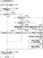
- FIG. 2 shows the mutual operation of the rollover risk degree judging device 20 and the roll angle estimating device 10.
- the roll angle / roll angular velocity detection unit 21 detects the roll angle ⁇ and the roll angular velocity ⁇ of the vehicle 1, gives the roll angular velocity ⁇ to the rollover risk determination unit 22, and processes the roll angle ⁇ .
- step S901 the roll angle / roll angular velocity detection unit 21 detects the roll angle ⁇ and the roll angular velocity ⁇ of the vehicle 1, gives the roll angular velocity ⁇ to the rollover risk determination unit 22, and processes the roll angle ⁇ .
- the processing unit 13 corrects the roll angle ⁇ and provides the corrected roll angle ⁇ AMD to the rollover risk determination unit 22 (step S902).
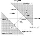
- the rollover risk determination unit 22 uses a two-dimensional map that shows the relationship between the roll angle ⁇ and the roll angular velocity ⁇ as shown in FIG. 3 and is stored in the two-dimensional map.
- Distances L1 and L2 from each of the boundary lines T1 and T2 to the point S specified by the roll angle ⁇ and the roll angular velocity ⁇ are calculated according to the following equations (1) and (2) (step S903).
- the boundary lines T1 and T2 are a stable region R1 indicating that there is no risk of the vehicle 1 rolling over, a left rollover risk region R2L indicating that there is a risk of the vehicle 1 rolling over to the left, and a right side.
- R2R right rollover risk area
- A1 and B1 in the above equation (1) are the ⁇ axis intercept and the ⁇ axis intercept of the boundary line T1
- A2 and B2 in the above equation (2) are the boundary line T2.
- ⁇ -axis intercept and ⁇ -axis intercept are the boundary line T1
- step S904 YES
- the rollover risk determination unit 22 determines that there is no risk of rollover (within the stable region R1) and does not perform any control (step S907).
- step S905 YES
- the rollover risk determination unit 22 determines that there is a risk of left rollover (within the left rollover risk area R2L), and sets the distance L1 to the rollover risk H (Step S908).
- step S906 the rollover risk determination unit 22 determines that there is a risk of right rollover (within the right rollover risk area R2R), and sets the distance L2 to the rollover risk H. (Step S909).
- the distance L1 is adopted as the value of the rollover risk degree H when there is a risk of rollover to the left and the distance L2 when there is a risk of rollover to the right.
- the rollover risk degree determination unit 22 calculates a target deceleration G target necessary for preventing the vehicle 1 from rollover from the rollover risk degree H, and supplies the target deceleration G target to the brake controller 23 (step S910).
- the target deceleration G target is not limited to the one calculated by multiplying the rollover risk degree H by the coefficient K as shown in the figure, but may be any one that changes according to the increase or decrease of the rollover risk degree H.
- the brake controller 23 calculates the brake pressure necessary for each wheel so as to achieve the target deceleration G target and performs brake control (step S912).
- the rollover risk determination unit 22 determines a system error and records an error flag in the rollover risk determination device 20 (step S911).
- the rollover risk determination unit 22 outputs the rollover risk H to the outside, and performs an alarm control according to the rollover risk H instead of the brake controller 23 described above. (Not shown). In this case as well, the above description applies in the same manner.
- the rollover risk level is determined based on the roll angle and the roll angular velocity that continuously change according to the traveling state of the vehicle 1, and brake control, alarm control, and the like according to the rollover risk level can be performed. Thus, it is possible to prevent the vehicle 1 from overturning.
- the rollover risk determination device 20 calculates the distances L1 and L2 using the corrected roll angle ⁇ AMD obtained by the roll angle correction process, even if the vehicle height adjustment is performed, The rollover risk determination device 20 can accurately determine the rollover risk H of the vehicle 1.
- K ⁇ 1 , ⁇ 1 , K ⁇ 12 , and ⁇ 2 in the above equation (3) are respectively known fixed roll stiffness coefficients common to the suspensions 5L and 5R determined by design conditions and the like, and suspensions 5L and 5R.
- equation of balance of roll moments on the suspensions 3L and 3R side can be expressed by the following equation (4).
- M x2 and K ⁇ 2 in the above formula (4) are common to the suspensions 3L and 3R determined by the unknown roll moment generated by the suspensions 3L and 3R, the design conditions, etc. in accordance with the vehicle height adjustment, respectively.
- a known fixed roll stiffness coefficient is used to estimate the roll stiffness of the suspensions 3L and 3R.
- the roll stiffness coefficient K .phi.1 to define the vehicle-specific roll stiffness coefficient K ⁇ 13 by K .phi.2 and frame torsional rigidity coefficient K .phi.12, in the above formula (6) Focusing on the fact that the expressed roll moment M x is constant as long as the loading condition of the load does not change, any two time points at which vehicle height adjustment (at least a part from the adjustment start time to the end time) intervenes.
- the equality relationship shown in the following formula (8) is established between the moment M x2b and the roll angle ⁇ 2b .
- the loads F La and F Ra to the suspensions 3L and 3R are calculated from the internal pressures P La and P Ra at the first time point according to the following equation (10).
- the above expression (10) is a linear approximation expression (k and m are coefficients determined by design conditions) indicating the load-internal pressure characteristics commonly exhibited by the suspensions 3L and 3R themselves. As shown in FIG. P L and P loads from R F L and F R are uniquely identified respectively.
- the roll moment M x2a by the sun pensions 3L and 3R at the first time point is calculated using the loads F La and F Ra calculated by the above formula (10) according to the following formula (12).
- the roll moment M x2b by Sun B 3L and 3R in the second time is calculated using the load F Lb and F Rb calculated by the formula (11).
- trd is the distance between each sun pension 3L and 3R-roll center (not shown) (tread length, distance from the left and right center to each sun pension 3L and 3R).
- the roll angle ⁇ 2a at the first time point is calculated using the displacements Z La and Z Ra at the first time point according to the following equation (13).
- the roll angle ⁇ 2b at the second time point is calculated using the displacements Z Lb and Z Rb at the second time point according to the following equation (13).
- the roll stiffness coefficient K ⁇ 13 is calculated using the above formula (9) using the roll moments M x2a and M x2b calculated by the above formula (12) and the roll angles ⁇ 2a and ⁇ 2b calculated by the above formula (13). ).
- Z Les and Z Res in the above equation (16) are the displacements of the suspensions 3L and 3R when the vehicle height adjustment is not executed, respectively.
- the constant b is deleted when the difference between the displacements Z Les and Z Res is taken.
- a plurality of first-order coefficients a and constants b in the above equation (15) are obtained in advance by experiments or the like as shown in FIG. 6, for example. That is, in the experimental stage, the internal pressure P when the reference length P 1, P 2, and fixed to the ⁇ P 7 (P 1 ⁇ P 2 ⁇ ⁇ P 7) in a state of containment air The load F applied to the suspension 3L or 3R is sequentially changed, and the displacement Z at each time is measured.
- actual load-displacement characteristics CF1 to CF7 indicated by dotted lines in FIG.
- the table shown in FIG. 2B shows the internal pressure P and the values of the first-order coefficients a1 to a7 and the constants b1 to b7 in the linear approximation expressions EXP1 to EXP7 in association with each other.
- the primary coefficient a and the constant b are proportional to the internal pressure P. This is shown on the graph in FIGS. 7A and 7B, and the primary coefficient a and the constant b are expressed by the following formula (17).
- the vehicle height adjusting device 30 pressurizes one internal pressure of the suspensions 3L and 3R, and reduces the other internal pressure by the pressurization. Therefore, the average value between the internal pressure P Lb and P Rb (not shown) is equal to the internal pressure average value of the suspension 3L and 3R in the second time point, the mean value between the internal pressure P Lb and P Rb second
- the primary coefficient a at the time can be uniquely specified from the data table of FIG. 6B or the graph of FIG.
- the primary coefficient a may be selected using the internal pressures P La and P Ra at the first time point.
- the roll angle ⁇ 2es when the vehicle height adjustment is not executed is determined by the roll moments M x2a and M x2b by the suspensions 3L and 3R at the first time point and the second time point, and the first time point and the second time point. Is calculated according to the above equation (21) using the roll angles ⁇ 2a , ⁇ 2b , the tread length trd, and the primary coefficient a in the above equation (17).
- the roll angle ⁇ 2es when the vehicle height adjustment is not executed is estimated using the roll stiffness coefficient K ⁇ 13 calculated according to the above equation (9), but the vehicle height adjustment starts from the start of the vehicle. Until it is started (period immediately after starting), the internal pressure P and the displacement Z at two points in time where the state of the suspension 3 is different cannot be detected, and the roll stiffness coefficient K ⁇ 13 is set according to the above equation (9). It is not possible to calculate and estimate the roll angle ⁇ 2es when the vehicle height adjustment is not executed according to the above equation (21).
- a load in which the moment Mx changes due to a light load state with a light load a middle load state in which the load center is approximately the center of the left or right, or a change in the load state of the load during load adjustment (load change, load collapse, etc.)
- the accuracy of the roll stiffness coefficient K ⁇ 13 calculated according to the above equation (9) is reduced, and the accuracy of the roll angle ⁇ 2es calculated when the vehicle height adjustment is not executed is also reduced according to the above equation (21).
- the absolute value when the state change of the suspension 3 at two different time points is small (the denominator ((M x2a ⁇ M x2b ) + 2 ⁇ trd 2 ⁇ a ( ⁇ 2b ⁇ 2a )) of the above equation (21). Is small), the accuracy of the roll angle ⁇ 2es when the vehicle height adjustment is not executed, which is calculated according to the above equation (21), is reduced.
- the second estimation method is a method for calculating the roll angle ⁇ 2es with relatively high accuracy in each of the above cases where the disadvantage of the first estimation method occurs, and the roll stiffness coefficient according to the above equation (9).
- the roll angle ⁇ 2es is calculated using the roll moments M x2a and M x2b and the roll angles ⁇ 2a and ⁇ 2b at two different time points (first and second time points).
- the roll moment M x2 and the roll angle ⁇ 2 at any one time point and the roll stiffness coefficient K ⁇ 13def or K ⁇ 13new stored before obtaining these detected values Is used to calculate the roll angle ⁇ 2es . That is, the correction roll angle ⁇ 2off of the second estimation method is not the roll moments M x2a and M x2b and the roll angles ⁇ 2a and ⁇ 2b at two different time points, but the roll moment M x2 and the roll at one time point.
- the angle ⁇ 2 and a predetermined roll stiffness coefficient K ⁇ 13def (or K ⁇ 13new ) the calculation is performed according to the above equation (20).
- the default roll stiffness coefficient K ⁇ 13def is obtained in advance by experiments, simulations, etc., and stored for each vehicle.
- the difference in reliability of the calculated roll angle ⁇ 2es is likely to occur due to the detection environment such as the fluctuation state of the air suspension 3 and the change in the state of the load.
- a highly reliable and highly accurate roll angle ⁇ 2es can be obtained.
- the reliability under a suitable detection environment is lower than that in the first estimation method, but the difference in reliability due to the detection environment is less likely to occur than in the first estimation method.
- a roll angle ⁇ 2es that is stable in terms of properties can be obtained.
- the roll angle ⁇ 2es when the vehicle height adjustment is not executed is the first state in which the first method can be obtained with a desired accuracy.
- roll angle ⁇ 2es when vehicle height adjustment is not executed is obtained.
- vehicle height adjustment is not executed according to the second method.
- the roll angle ⁇ 2es is obtained. That is, the first method and the second method are appropriately selected and used in accordance with the variation state of the suspension 3 and the load state change.
- the corrected roll angle ⁇ 2off is calculated from the roll angle ⁇ 2es and the roll angle ⁇ 2b at the second time point according to the following equation (22). Note that “0” is set as the initial value of the correction roll angle ⁇ 2off .
- the corrected roll angle ⁇ AMD is calculated by adding the corrected roll angle ⁇ 2off to the detected roll angle ⁇ according to the following equation (23).
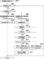
- FIGS. 8 to 11 Next, an example of roll angle correction processing executed by the roll angle estimation apparatus 10 will be described with reference to FIGS. In this processing example [1], the roll angle ⁇ 2es when the vehicle height adjustment is not executed is estimated only by the first estimation method.
- the processing unit 13 that initiated the processing were detected displaced by the internal pressure P L and P R and the displacement detecting unit 11 measured by the pressure measuring section 12 Z L and Z R (detection data) Each time is input, the Butterworth filter process shown in FIG. 9 is executed (step S101).
- step S101 when the processing unit 13 starts this process (step S101), it acquires detection data (P L , P R , Z L , Z R ) (step S201), and detects these detections.
- Butterworth filter processing is performed on the data, and each detection value after the filter processing is accumulated and stored in time series, and every time the latest detection data is acquired, the most recent predetermined number n of samples including the latest detection data (n is a natural number not less than 1) calculates an average value of the data, the calculated average value (P Lave, P Rave, Z Lave, Z Rave) pressure used in the correction process P L, P R and the displacement Z L, updates and stores a Z R (step S202).
- the processing unit 13 executes an acceleration generation flag creation process shown in FIG. 10 (step S101).
- step S102 when the processing unit 13 starts this processing (step S102), it is determined whether or not the latest detected acceleration acquired from the acceleration measurement unit 14 is less than a predetermined acceleration (threshold A). Is determined (step S301).
- step S301 When the detected acceleration is less than the predetermined acceleration (step S301: YES), the processing unit 13 determines that the update is not prohibited, sets the acceleration generation flag F1 to “0” (off) (step S302), The process proceeds to step S102 in FIG.
- step S301 when the detected acceleration is equal to or higher than the predetermined acceleration (step S301: NO), the processing unit 13 determines that the update is prohibited and sets the acceleration generation flag F1 to “1” (on) (step S303). ), The process proceeds to step S102 in FIG.
- This predetermined acceleration maintains the load state so that the roll angle ⁇ 2es when the vehicle height adjustment is not executed can be estimated with a desired accuracy during acceleration / deceleration, turning, running on a slope, or running on a road surface having a cant (crossing gradient). It is preset and stored as an upper limit threshold value of acceleration (the absolute value of acceleration when acceleration is detected in positive and negative directions).
- the processing unit 13 determines whether or not the vehicle height adjustment has been completed (step S103). Specifically, the vehicle height adjustment device 30 even after having received the vehicle height adjustment start signal SG S, if before receiving the vehicle height adjustment end signal SG F, height adjustment is not completed (car In other cases, it is determined that the vehicle height adjustment has been completed.
- step S103 When it is determined that the vehicle height adjustment has been completed (step S103: YES), the processing unit 13 sets the point A non-acquisition flag F2 to “1” (on) (step S104), and before the start of this process.
- the post-correction roll angle ⁇ AMD is calculated by adding the latest stored correction roll angle ⁇ 2off to the detected roll angle ⁇ (step S105), and the process is terminated.
- the post-correction roll angle ⁇ AMD calculated in this way is provided to the rollover risk determination unit 22 (shown in FIG. 1).
- the A point non-acquisition flag F2 is a flag indicating that the internal pressures P La and P Ra and the displacements Z La and Z Ra immediately after the start of the vehicle height adjustment (first time point) have not yet been acquired.
- step S103 determines whether or not the acceleration generation flag F1 is off.
- step S106 When the acceleration generation flag F1 is off (step S106: YES), the processing unit 13 determines whether the point A non-acquisition flag is on or off (step S107), and the point A non-acquisition flag is on. If it is (step S107: YES), Butterworth filtering (step S101) the internal pressure P L stored in, P R and the displacement Z L, the internal pressure P La of Z R a vehicle height adjustment immediately after the start (first time point), P Ra and displacements Z La and Z Ra are acquired and stored (step S108), the A point not acquired flag is set to “0” (off) (step S109), and the latest stored before starting this processing The corrected roll angle ⁇ 2off is added to the detected roll angle ⁇ to calculate the corrected roll angle ⁇ AMD (step S105), and the process is terminated.
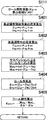
- Step S107 if the point A not acquired flag is off (Step S107: NO), Butterworth filtering pressure P L, P R and the displacement Z L, in the vehicle height adjusting Z R stored in (step S101) (second Are acquired as internal pressures P Lb and PRb and displacements Z Lb and Z Rb (step S110), and the roll stiffness coefficient calculation process shown in FIG. 11 is executed (step S111).
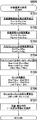
- step S111 when the processing unit 13 starts this process (step S111), the internal pressures P La and P Ra immediately after the vehicle height adjustment start stored in the previous step S108 are used.
- the loads F La and F Ra immediately after the start of the vehicle height adjustment are calculated according to the equation (10) (step S401), and the above-described equation (10) is calculated using the internal pressures P Lb and P Rb during the vehicle height adjustment acquired in step S110.
- step S402 Calculate the loads F Lb and F Rb during the vehicle height adjustment according to 11) (step S402), and use the calculated loads F La , F Ra , F Lb , and F Rb according to the above formula (12).
- Roll moments M x2a and M x2b are calculated (step S403). Subsequently, the processing unit 13 uses the displacements Z La and Z Ra immediately after the start of the vehicle height adjustment stored in the previous step S108 and the displacements Z Lb and Z Rb during the vehicle height adjustment acquired in step S110, The roll angles ⁇ 2a and ⁇ 2b are calculated according to the above equation (13) (step S404), and the calculated roll moments M x2a and M x2b and the roll angles ⁇ 2a and ⁇ 2b are used according to the above equation (9). The roll stiffness coefficient K ⁇ 13 is calculated (step S405), and the process proceeds to step S112 in FIG.
- the processing unit 13 that has calculated the roll stiffness coefficient K ⁇ 13 selects the load-displacement characteristic (primary approximation coefficient a) using the internal pressures P La , P Ra , P Lb , P Rb as shown in FIG. Step S112) Using the calculated roll stiffness coefficient K ⁇ 13 and the selected primary coefficient a, the roll angle ⁇ 2es when vehicle height adjustment is not executed is calculated according to the above equation (20) (Step S113). Using the roll angle ⁇ 2b and the roll angle ⁇ 2es , the correction roll angle ⁇ 2off is calculated according to the above equation (22), and the calculated correction roll angle ⁇ 2off is updated and stored (step S114). The corrected roll angle ⁇ AMD is calculated by adding the corrected roll angle ⁇ 2off calculated in step S114 to the detected roll angle ⁇ (step S105), and the process is terminated.
- the roll angle ⁇ AMD is calculated by adding the corrected roll angle ⁇ 2off calculated in step S114 to the detected roll angle ⁇ (step S105), and the
- step S106 When the acceleration generation flag F1 is on (step S106: NO), the processing unit 13 does not execute the processing of steps S107 to S114 (processing for calculating and updating the corrected roll angle ⁇ 2off ) and starts this processing.
- the post-correction roll angle ⁇ AMD is calculated by adding the latest correction roll angle ⁇ 2off stored previously to the detected roll angle ⁇ (step S105), and this processing is terminated.
- FIGS. 9, 10, 12 to 18 Next, another example of the roll angle correction process executed by the roll angle estimation apparatus 10 will be described with reference to FIGS. 9, 10 and 12 to 18.
- the roll angle ⁇ 2es when the vehicle height adjustment is not executed is estimated by using both the first estimation method and the second estimation method.
- the roll angle ⁇ 2es is calculated by the second estimation method. Further, in this processing example [2], the roll stiffness coefficient K ⁇ 13 is updated when a predetermined criterion is satisfied, and the roll stiffness coefficient K ⁇ 13 is not updated when the criterion is not satisfied.
- the predetermined criterion will be described.
- the roll angle ⁇ 2es when the vehicle height adjustment is not executed is in a first state in which the first estimation method can be obtained with a desired accuracy, and the roll when the vehicle height adjustment is not executed using the first estimation method.
- the roll angle ⁇ 2es is obtained with a desired accuracy using the first method. It is determined that the second state is impossible, and the roll angle ⁇ 2es when the vehicle height adjustment is not executed is obtained according to the second method.
- a roll moment M xb due to unbalanced load is calculated according to the following equation (25).
- the roll stiffness coefficient K ⁇ 13 used in the equation (25) is the latest roll stiffness coefficient K ⁇ 13new updated and stored in step S43 described later.
- the difference between the roll moment M xb due to the load unbalance at the end of the vehicle height adjustment and the roll moment M xa due to the load unbalance at the start of the vehicle height adjustment is defined as the uneven moment difference ⁇ M x , and the roll moment M x2a and It calculates according to the following formula
- the roll stiffness coefficient K ⁇ 13 used in the equations (26) and (27) is the latest roll stiffness coefficient K ⁇ 13new updated and stored in step S807 or step S808 described later.
- ) of the denominator of equation (21) is calculated as a predetermined state value of the suspension 3, and whether the calculated value exceeds a predetermined threshold value H set in advance Determine whether or not.
- the threshold values used in each of the load determination, the load movement determination, and the suspension 3 state change determination may be the same or different.
- the threshold value used in each of the empty vehicle determination, middle load determination, load movement determination, and suspension 3 state change determination is made different between the estimation method determination and the update determination.
- the empty vehicle determination threshold at the time of the estimation method determination is represented as “B”
- the medium load determination threshold is “C”
- the load movement determination threshold is “D”
- the state change determination threshold of the suspension 3 is represented as “H”.
- the empty vehicle determination threshold value at the time is represented as “E”, the medium load determination threshold value as “F”, the load movement determination threshold value as “G”, and the state change determination threshold value of the suspension 3 as “I”.
- the predetermined acceleration can be estimated so that the roll angle ⁇ 2es and the roll stiffness coefficient K ⁇ 13 can be estimated with desired accuracy in acceleration / deceleration, turning, running on a slope or running on a road surface having a cant (crossing gradient), etc.
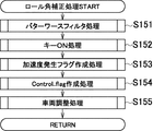
- the roll angle correction process in the processing unit 13 includes (1) the result of removing noise from the output values (measured values) acquired from the displacement detecting unit 11 and the pressure measuring unit 12 (displacement Z L , Z R and internal pressures P L , P R ) that are constantly updated (step S151), and (2) key ON processing that estimates the roll angle ⁇ 2es immediately after the key ON (start of the vehicle 1) (step S152). (3) Acceleration generation flag generation processing for setting an acceleration generation flag (step S153), (4) Control flag generation processing processing for setting a control flag (step S154), and (5) Roll angle during vehicle height adjustment. vehicle height adjustment processing (step S155) for estimating ⁇ 2es and calculating a corrected roll angle ⁇ AMD based on the estimated roll angle ⁇ 2es .
- the processing unit 13 performs a key ON process.
- the key ON process is a process executed in the key ON phase from the start of the vehicle 1 to the start of vehicle height adjustment.
- the processing unit 13 sets the key ON mode flag to “1” (ON) when the engine of the vehicle 1 is started (for example, the ignition switch is ON), and sets the key ON mode flag when the vehicle height adjustment start signal SG s is received. Set to “0” (off).
- the vehicle height adjustment is not executed by the second estimation method. Estimate the current roll angle ⁇ 2es .
- step S152 the processing unit 13 determines whether the key ON phase is set (step S251). Specifically, it is determined that the key ON phase is ON when the key ON mode flag is ON, and it is determined that the key ON face is not set when OFF. If it is determined that it is not the key ON phase (step S251: NO), this process is terminated.
- step S251 If it is determined that the key ON phase (step S251: YES), the processing unit 13, filtered pressure stored in (step S151) P L, P R and the displacement Z L, the internal pressure immediately after the key ON to Z R P L0 , obtained as P R0 and displacement Z L0, Z R0 (step S252), using the internal pressure P L0, P R0 acquired, calculating the load F L0, F R0 immediately after key ON in accordance with the above equation (10) (Step S253) Using the calculated loads F L0 and F R0 , roll moment M x20 by the suspension 3 is calculated according to the above equation (12) (step S254), and the obtained displacements Z L0 and Z R0 are used.
- the roll angle ⁇ 20 is calculated according to the above equation (13) (step S255). Subsequently, the processing unit 13 selects the load-displacement characteristic (primary approximation coefficient a) using the internal pressures P L0 and P R0 (step S256), and calculates the roll moment M x20 and the roll angle ⁇ 20 calculated above. Using the stored roll stiffness coefficient K ⁇ 13 and the selected primary coefficient a, the roll angle ⁇ 2es when vehicle height adjustment is not executed is calculated according to the above equation (20) (step S257). As the roll stiffness coefficient K ⁇ 13 , the latest roll stiffness coefficient K ⁇ 13new updated and stored in step S807 of the vehicle height adjustment OFF process (step S554) described later is used. When the vehicle height adjustment OFF process is omitted, a preset roll stiffness coefficient K ⁇ 13def that is preset and stored is used.
- the processing unit 13 that calculates the roll angle ⁇ 20 and the roll angle ⁇ 2es when the vehicle height adjustment is not executed calculates the corrected roll angle ⁇ 2off according to the above equation (22), and calculates the calculated corrected roll angle ⁇ 2off . Update and store (step S258), and the process ends.
- FIG. 13 After the process (2), the processing unit 13 executes an acceleration generation flag generation process. Note that the details of the processing are the same as in the above processing example [1], and thus detailed description thereof is omitted.
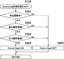
- Control flag generation processing FIG. After the process (3), the processing unit 13 executes a control flag generation process. In this control flag generation process, the processing unit 13 determines whether or not the vehicle height adjustment device 30 is executing vehicle height adjustment, whether or not the suspension 3 is deformed in a displacement region that can be linearly approximated, and whether the suspension is linearly approximated. It is determined whether or not the pressure is deformed in a possible pressure region.
- the upper limit threshold Z High and the lower limit threshold Z Low of the displacement Z of the air suspension 3 that cannot be linearly approximated, and the upper limit threshold P High and the lower limit threshold P Low of the internal pressure P of the air suspension 3 are set in advance.
- the spring of the air suspension 3 It can be determined that the update prohibition state is outside the range in which the characteristic can be linearly approximated.
- the roll stiffness coefficient K ⁇ 13 and the vehicle height adjustment are not executed on the assumption that the air suspension 3 is deformed within a range of displacement and internal pressure that can be linearly approximated. Therefore , if the spring characteristics of at least one of the left and right suspensions 3 are out of the range that can be linearly approximated, the accuracy of these calculated values decreases.
- the processing unit 13 determines that the update is prohibited, sets the control flag to “0” (off), and sets a roll stiffness coefficient to be described later. K Update processing of ⁇ 13 and update processing of correction roll angle ⁇ 2off are prohibited.
- step S154 when the processing unit 13 starts this processing (step S154), whether or not the vehicle height adjusting device 30 is adjusting the vehicle height (whether the vehicle height adjustment is within the period from the start to the end of the vehicle height adjustment). the not) is determined on the basis of the reception of the vehicle height adjustment start signal SG S and height adjustment end signal SG F (step S451).
- step S451 If it is determined that the vehicle height adjustment has not been executed (step S451: NO), the processing unit 13 sets the control flag to off (step S455), and ends this process.
- step S451 If it is determined that the running vehicle height adjustment (step S451: YES), the processing unit 13, displacement Z L stored in the filtering process (step S151), reads the Z R, the read displacement Z L, is Z R It is determined whether both are in the range exceeding the lower threshold Z Low and lower than the upper threshold Z High (Z Low ⁇ Z L , Z R ⁇ Z High ) (step S452).
- step S452 If it is determined that at least one of the displacements Z L and Z R is out of the above range (step S452: NO), the processing unit 13 sets the control flag to off (step S455), and ends this process.
- step S452 YES
- the processing unit 13 the internal pressure P L stored in the filtering process (step S151)
- reads the P R the read pressure P L, P R are both determines whether the range and less than the upper threshold P High exceed the lower threshold P Low (P Low ⁇ P L , P R ⁇ P High) (step S453).
- step S453 when it is determined that P R are both within the above range (step S453: YES), the processing unit 13 is set to on control flag (step S454), the process ends.
- FIGS. 15 to 18 After the process (4), the processing unit 13 performs a vehicle height adjustment process.
- step S155 when the processing unit 13 starts this processing (step S155), the processing unit 13 determines whether or not the control flag is on (step S551).
- step S551: YES When the control flag is on (step S551: YES), the processing unit 13 executes the vehicle height adjustment ON process (step S552) shown in FIG. 16, and when it is off (step S551: NO), the vehicle shown in FIG. High adjustment OFF processing (step S554) is executed.
- step S552 when the processing unit 13 starts this process (step S552), it determines whether or not the acceleration generation flag F1 is off (step S601), and the acceleration generation flag F1 is set. When it is determined that it is off (step S601: YES), it is determined whether or not the point A non-acquisition flag F2 is on (step S602).
- step S602 If point A unacquired flag F2 is determined to be ON (step S602: YES), the processing unit 13, the internal pressure P L stored at Butterworth filter process (step S151), P R and the displacement Z L, the Z R Acquired and stored as internal pressures P La and P Ra and displacements Z La and Z Ra immediately after the start of vehicle height adjustment (first time point) (step S603), and set the A point non-acquisition flag to OFF (step S604) Then, the process proceeds to step S553 in FIG.
- step S602 if the point A not acquired flag is determined to be OFF (step S602: NO), the internal pressure P L stored at Butterworth filter process (step S151), P R and the displacement Z L, the vehicle height of the Z R Acquired as internal pressures P Lb and P Rb and displacements Z Lb and Z Rb during adjustment (second time point) (step S605), the state quantity calculation process shown in FIG. 17 is executed (step S606).
- step S606 when the processing unit 13 starts this process (step S606), the internal pressures P La and P Ra immediately after the vehicle height adjustment start stored in the previous step S603 are used.
- the loads F La and F Ra immediately after the start of the vehicle height adjustment are calculated according to the equation (10) (step S701), and the above-described equation (11) is used using the internal pressures P Lb and P Rb during the vehicle height adjustment acquired in step S605.
- step S702 the support load F Lb in the vehicle height adjustment, F Rb calculated according) (step S702), the support load F a suspension 3 immediately after the vehicle height adjustment starting, calculated load F La, calculated as the sum of F Ra,
- the support load F b of the suspension 3 during the vehicle height adjustment is calculated as the sum of the calculated loads F Lb and F Rb (step S703).
- the processing unit 13 uses the calculated loads F La , F Ra , F Lb , and F Rb to calculate the roll moments M x2a and M x2b by the suspension 3 according to the above equation (12), and two different values are obtained.
- the processing unit 13 uses the displacements Z La and Z Ra immediately after the start of the vehicle height adjustment stored in the previous step S603 and the displacements Z Lb and Z Rb during the vehicle height adjustment acquired in step S605,
- the processing unit 13 uses the calculated roll moment change amount ⁇ M ( ⁇ M x2 ) and the roll angle change amount ⁇ , according to the above equation (27), and the roll moment change amount (diffuse moment difference).
- the processing unit 13 that has finished the state quantity calculation process determines whether or not the vehicle is in an empty state (step S607), and determines that the vehicle is not in an empty state (step S607: YES). It is determined whether or not it is in a state (step S608), and if it is determined that it is not in a middle load state (step S608: YES), it is determined whether or not it is in a load movement state (step S609) and is not in a load movement state. Is determined (step S609: YES), it is determined whether or not the state of the suspension 3 has changed to such an extent that the highly reliable roll stiffness coefficient K ⁇ 13 can be calculated (step S613).
- step S613 If it is determined that the state of the suspension 3 has changed more than the calculation of the highly reliable roll stiffness coefficient K ⁇ 13 , not any of the empty state, the middle load state, and the load movement state (step S613: YES), the processing The unit 13 calculates the roll angle ⁇ 2es when the vehicle height adjustment is not executed by the first estimation method (step S610). Specifically, the roll moment M x2b , the roll angle ⁇ 2b , the roll moment change ⁇ M and the roll angle change ⁇ calculated in steps S704 and S705, and the primary approximation coefficient a selected in step S707 are used. Using, the roll angle ⁇ 2es is calculated according to the above equation (21).
- step S607 NO
- step S608 NO
- step S609 NO
- step S613 NO
- the processing unit 13 calculates the roll angle ⁇ 2es when the vehicle height adjustment is not executed by the second estimation method (step S612). .
- the processing unit 13 that has calculated the roll angle ⁇ 2es when the vehicle height adjustment is not executed calculates the corrected roll angle ⁇ 2off according to the above equation (22), and updates and stores the calculated corrected roll angle ⁇ 2off. (Step S611), the process proceeds to Step S553 in FIG.
- step S601 If it is determined in step S601 that the acceleration generation flag F1 is on (step S601: NO), the processing unit 13 does not execute the calculation and update processing of the correction roll angle ⁇ 2off in steps S602 to S611. Control proceeds to step S553 in FIG.
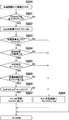
- step S554 when the processing unit 13 starts this process (step S554), it determines whether or not it is the falling edge (at the time of falling) of the control flag (step S801). ).
- step S801 If it is determined that it is a falling edge of the control flag (step S801: YES), the processing unit 13 sets the point A non-acquisition flag F2 to “1” (on) (step S802), and the acceleration generation flag F1 is off. It is determined whether or not.
- step S804 determines whether or not the vehicle is in an empty state (step S804), and determines that the vehicle is not in an empty state (step S804: YES). It is determined whether or not it is in the middle load state (step S804), and if it is determined that it is not in the middle load state (step S804: YES), it is determined whether or not it is in the load movement state (step S806). If it is determined that it is not (step S6806: YES), it is determined whether or not the state of the suspension 3 has changed to such an extent that a highly reliable roll stiffness coefficient K ⁇ 13 can be calculated (step S809).
- step S809 YES
- K ⁇ 13 is updated and stored as the latest roll stiffness coefficient K ⁇ 13new (step S807), and the process proceeds to step S553 in FIG.
- the processing unit 13 updates the roll stiffness coefficient K ⁇ 13 to the default value ( K ⁇ 13def ) and stores it (step S808). Then, the process proceeds to step S553.
- step S553 in FIG. 15 the processing unit 13 calculates the corrected roll angle ⁇ AMD by adding the updated latest corrected roll angle ⁇ 2off to the detected roll angle ⁇ , and ends the present process.
- the post-correction roll angle ⁇ AMD calculated in this way is provided to the rollover risk determination unit 22 (shown in FIG. 1).
- the latest correction roll angle ⁇ 2off updated and stored in step S258 or step S611 is used.
- FIGS. 19 and 20 ⁇ Examples of Application of Roll Angle Correction Processing Examples [1] and [2] to a Connected Vehicle: FIGS. 19 and 20>
- the roll angle estimation device 10 can be applied not only to a single vehicle as shown in FIG. 1 but also to a connected vehicle.
- an application example to a connected vehicle will be described with reference to FIGS. 19 and 20.
- a vehicle 1 shown in FIG. 19 includes a tractor 100 provided with suspensions 3L and 3R and 5L and 5R in the vicinity of left and right rear wheels 2L and 2R and left and right front wheels 4L and 4R, and a coupler (not shown) and the like for the tractor 100. And the suspensions 7L and 7R are provided in the vicinity of the left and right wheels 6L and 6R, respectively, and the suspensions 3L and 3R are subject to vehicle height adjustment (injection or discharge of air AP by the vehicle height adjustment device 30). ing.
- the displacement detection unit 11L and the pressure measurement unit 12L in the roll angle estimation device 10 similar to FIG. 1 are connected to the suspension 3L, and the displacement detection unit 11R and the pressure measurement unit 12R are connected to the suspension 3R.
- the processing unit 13 in the roll angle estimation device 10 is not performing vehicle height adjustment by the above-described first estimation method and second estimation method, similarly to the unconnected vehicle shown in FIG. 1.
- the corrected roll angle ⁇ 2es and the corrected roll angle ⁇ AMD can be calculated.
- K ⁇ 3 in the above equation (29) is a known fixed roll stiffness coefficient common to the suspensions 7L and 7R determined by the design conditions and the like.
- Equation (30) can be expressed by the following equation (32) using a coefficient K * ⁇ 1 defined as shown in the following equation (31).
- the roll stiffness coefficient K ⁇ 13 is obtained from the roll moments M x2a and M x2b and the roll angles ⁇ 2a and ⁇ 2b at the start and end of the vehicle height adjustment, as in the case of the single vehicle (equation (7)). be able to.
- said Formula (33) can be represented by the following formula
- the processing unit 13 determines the roll angle ⁇ 2es when the vehicle height adjustment is not executed, the roll moments M x2a and M x2b due to the suspensions 3L and 3R at the first time point and the second time point, and the first time point and the first time point. 2 using the roll angles ⁇ 2a , ⁇ 2b , the tread length trd, and the primary coefficient a in the above equation (17), the corrected roll angle ⁇ 2off , and the corrected roll angle ⁇ AMD can be calculated. That is, the roll angle ⁇ 2es when the vehicle height adjustment is not executed can be estimated by the first estimation method described above, and the corrected roll angle ⁇ 2off and the corrected roll angle ⁇ AMD can be calculated.
- the roll moment M x2 and the roll angle ⁇ 2 at one time point, and the roll stiffness coefficient K ⁇ 13def or K ⁇ 13new stored before obtaining these detected values are also possible. It is also possible to calculate the roll angle ⁇ 2es using That is, also by the above-described second estimation method, it is possible to estimate the roll angle ⁇ 2es when the vehicle height adjustment is not executed and calculate the corrected roll angle ⁇ 2off and the corrected roll angle ⁇ AMD .
- the processing unit 13 can calculate the post-correction roll angle ⁇ AMD by executing the same processing as in the case of a single vehicle.
- steps S607 to S609 and S613 may be omitted, and one or more of steps S804 to S806 and S809 may be omitted.
- Whether the acceleration generation flag F1 is off (determination of whether the detected acceleration is less than the predetermined acceleration) is determined before the roll rigidity coefficient K ⁇ 13 update process or the corrected roll angle ⁇ 2off update process. What is necessary is just to carry out at arbitrary timings.
- the roll angle estimating apparatus 10 each time for calculating the roll angle phi 2ES during the vehicle height adjustment is not executed, it may be notified in a visually recognizable manner the driver of the calculated roll angle phi 2ES.
- a display unit may be provided in front of the driver's seat in the passenger compartment, and the calculated roll angle ⁇ 2es may be displayed on the display unit in a predetermined display mode.
- Preset display mode may be a numerical display of the roll angle phi 2ES, state changes in accordance with the value of the roll angle phi 2ES (e.g. stretching, moving, discoloration, etc.), or the like to the indicator.
- the present invention is widely applicable to vehicles equipped with an air suspension.
Landscapes
- Engineering & Computer Science (AREA)
- Mechanical Engineering (AREA)
- Physics & Mathematics (AREA)
- Automation & Control Theory (AREA)
- Mathematical Physics (AREA)
- Transportation (AREA)
- Vehicle Body Suspensions (AREA)
Abstract
車両に発生する加速度が予め設定された所定加速度以上である場合、更新禁止状態であると判定し、所定加速度未満である場合、更新禁止状態ではないと判定する。更新禁止状態ではないと判定した場合、求めた補正ロール角φ2offを更新して記憶し、更新禁止状態であると判定した場合、補正ロール角φ2offの更新を実行しない。
Description
本発明は、車両のロール角推定方法及び装置に関する。
特開2009-227265号公報には、車高調整非実行時のロール角を推定することが可能な方法及び装置が記載されている。この方法及び装置では、左右サスペンションの自動車高調整開始時の一定時間前から終了時の一定時間後までの任意の異なる2つの時点の各々において測定した各変位及び各内圧値から、それぞれ第1及び第2のロール角と左右サスペンションによる第1及び第2のロールモーメントとを算出し、ロール角及びロールモーメントから、サスペンションを装着した車両固有のロール剛性係数を算出する。サスペンションが示し得る内圧値をパラメータとして予め求めた複数個の変位特性の内、左右サスペンションの測定内圧平均値に対応する変位特性を、自動車高調整非実行時の左右サスペンションに共通の変位特性として選択する。第2のロール角及びロールモーメント、ロール剛性係数、及び上記選択した変位特性に基づき自動車高調整非実行時のロール角を求め、この自動車高調整非実行時のロール角を用いて自動車高調整による補正ロール角を決定する。そして、決定した補正ロール角によって検出ロール角を補正する。
上記従来の方法及び装置において、車両状態量を利用して自動車高調整非実行時のロール角を精度良く推定するためには、左右輪のロールモーメントが変化しないという前提が成立し、且つ積荷の荷重を正確に推定することが必要である。
しかし、車両が加減速中や旋回中の場合や、坂道或いはカント(横断勾配)を有する路面上にある場合、積荷の荷重が前後や左右に配分されたり、積荷に慣性力が発生するため、積荷の荷重を正確に推定することが難しく、また左右輪のロールモーメントが変化してしまう可能性が生じる。従って、このような環境下では、自動車高調整非実行時のロール角を精度良く推定することができず、検出ロール角の補正精度が低下する。
本発明は、上記実状に鑑みてなされたものであって、検出ロール角の補正精度の低下を抑制可能なロール角推定方法及び装置の提供を目的とする。
上記目的を達成すべく、本発明の第1の態様の車両のロール角推定方法は、車両に発生する加速度が予め設定された所定加速度以上である場合、更新禁止状態であると判定し、所定加速度未満である場合、更新禁止状態ではないと判定する第1ステップと、同一の荷重-変位特性及び荷重-内圧特性を有し、且つ自動車高調整の対象となる一部の左右サスペンションの自動車高調整開始時の一定時間前から終了時の一定時間後までのうち上記自動車高調整の少なくとも一部が間に介在する任意の異なる第1及び第2の時点の各々において測定された第1及び第2の変位並びに第1及び第2の内圧値から、第1及び第2のロール角と上記左右サスペンションによる第1及び第2のロールモーメントとをそれぞれ算出し、算出した第1及び第2のロール角並びに第1及び第2のロールモーメントから、上記サスペンションを装着した車両固有のロール剛性係数を算出し、上記サスペンションが示し得る内圧値をパラメータとして予め求めた複数個の荷重-変位特性のうち、上記左右サスペンションの測定内圧平均値に対応する荷重-変位特性を、上記自動車高調整が行われなかった場合の上記左右サスペンションに共通の荷重-変位特性として選択し、上記算出した第2のロール角及び第2のロールモーメントと、上記算出したロール剛性係数と、上記選択した荷重-変位特性とに基づき、上記自動車高調整が行われなかった場合のロール角を求める第2ステップと、上記第2ステップで求めた上記自動車高調整が行われなかった場合のロール角から上記第2ステップで算出した上記第2のロール角を減算することにより、上記自動車高調整による補正ロール角を求める第3ステップと、上記第1ステップで上記更新禁止状態ではないと判定した場合、上記第3ステップで求めた補正ロール角を更新して記憶し、上記第1ステップで上記更新禁止状態であると判定した場合、補正ロール角の更新を実行しない第4ステップと、を備える。
本発明の第2の態様の車両のロール角推定方法は、車両に発生する加速度が予め設定された所定加速度以上である場合、更新禁止状態であると判定し、所定加速度未満である場合、更新禁止状態ではないと判定する第1ステップと、同一の荷重-変位特性及び荷重-内圧特性を有し、且つ自動車高調整の対象となる一部の左右サスペンションの任意の時点において測定された変位及び内圧値から、ロール角と上記左右サスペンションによるロールモーメントとをそれぞれ算出し、上記サスペンションが示し得る内圧値をパラメータとして予め求めた複数個の荷重-変位特性のうち、上記左右サスペンションの測定内圧平均値に対応する荷重-変位特性を、上記自動車高調整が行われなかった場合の上記左右サスペンションに共通の荷重-変位特性として選択し、上記算出したロール角及びロールモーメントと、上記選択した荷重-変位特性と、上記サスペンションを装着した車両固有の値として上記変位及び内圧値の測定前に記憶されたロール剛性係数とに基づき、上記自動車高調整が行われなかった場合のロール角を求める第2ステップと、上記第2ステップで求めた上記自動車高調整が行われなかった場合のロール角から上記第2ステップで算出したロール角を減算することにより、上記自動車高調整による補正ロール角を求める第3ステップと、上記第1ステップで上記更新禁止状態ではないと判定した場合、上記第3ステップで求めた補正ロール角を更新して記憶し、上記第1ステップで上記更新禁止状態であると判定した場合、補正ロール角の更新を実行しない第4ステップと、を備える。
上記第1又は第2の態様の方法において、上記第1ステップは、上記第2及び第3ステップの前後の何れに実行してもよく、上記第2及び第3ステップと並行して実行してもよい。なお、上記第1ステップを上記第2及び第3ステップの前に実行し、且つ上記第1ステップで更新禁止状態であると判定した場合には、上記第2及び第3ステップの処理を実行しなくてもよい。
本発明の第1の態様の車両のロール角推定装置は、車両に発生する加速度が予め設定された所定加速度以上である場合、更新禁止状態であると判定し、所定加速度未満である場合、更新禁止状態ではないと判定する判定部と、同一の荷重-変位特性及び荷重-内圧特性を有し、且つ自動車高調整の対象となる一部の左右サスペンションの自動車高調整開始時の一定時間前から終了時の一定時間後までのうち上記自動車高調整の少なくとも一部が間に介在する任意の異なる第1及び第2の時点の各々において測定された第1及び第2の変位並びに第1及び第2の内圧値から、第1及び第2のロール角と上記左右サスペンションによる第1及び第2のロールモーメントとをそれぞれ算出し、算出した第1及び第2のロール角並びに第1及び第2のロールモーメントから、上記サスペンションを装着した車両固有のロール剛性係数を算出し、上記サスペンションが示し得る内圧値をパラメータとして予め求めた複数個の荷重-変位特性のうち、上記左右サスペンションの測定内圧平均値に対応する荷重-変位特性を、上記自動車高調整が行われなかった場合の上記左右サスペンションに共通の荷重-変位特性として選択し、上記算出した第2のロール角及び第2のロールモーメントと、上記算出したロール剛性係数と、上記選択した荷重-変位特性とに基づき、上記自動車高調整が行われなかった場合のロール角を求めるロール角決定部と、上記ロール角決定部が求めた上記自動車高調整が行われなかった場合のロール角から上記ロール角決定部が算出した上記第2のロール角を減算することにより、上記自動車高調整による補正ロール角を求める補正ロール角決定部と、上記更新禁止状態ではないと上記判定部が判定した場合、上記補正ロール角決定部が求めた補正ロール角を記憶部に更新して記憶し、上記更新禁止状態であると上記判定部が判定した場合、補正ロール角の更新を実行しない記憶制御部と、を備える。
本発明の第2の態様の車両のロール角推定装置は、車両に発生する加速度が予め設定された所定加速度以上である場合、更新禁止状態であると判定し、所定加速度未満である場合、更新禁止状態ではないと判定する判定部と、同一の荷重-変位特性及び荷重-内圧特性を有し、且つ自動車高調整の対象となる一部の左右サスペンションの任意の時点において測定された変位及び内圧値から、ロール角と上記左右サスペンションによるロールモーメントとをそれぞれ算出し、上記サスペンションが示し得る内圧値をパラメータとして予め求めた複数個の荷重-変位特性のうち、上記左右サスペンションの測定内圧平均値に対応する荷重-変位特性を、上記自動車高調整が行われなかった場合の上記左右サスペンションに共通の荷重-変位特性として選択し、上記算出したロール角及びロールモーメントと、上記選択した荷重-変位特性と、上記サスペンションを装着した車両固有の値として上記変位及び内圧値の測定前に記憶されたロール剛性係数とに基づき、上記自動車高調整が行われなかった場合のロール角を求めるロール角決定部と、上記ロール角決定部が求めた上記自動車高調整が行われなかった場合のロール角から上記ロール角決定部が算出したロール角を減算することにより、上記自動車高調整による補正ロール角を求める補正ロール角決定部と、上記更新禁止状態ではないと上記判定部が判定した場合、上記補正ロール角決定部が求めた補正ロール角を記憶部に更新して記憶し、上記更新禁止状態であると上記判定部が判定した場合、補正ロール角の更新を実行しない記憶制御部と、を備える。
上記所定加速度は、加減速、旋回走行、坂道或いはカント(横断勾配)を有する路面の走行などにおいて、自動車高調整非実行時のロール角を所望の精度で推定可能に積荷状態を維持する加速度(加速度が正負の方向で検出される場合には、加速度の絶対値)の上限閾値として、予め設定され記憶される。
上記第1又は第2の態様の方法及び装置では、車両に発生する加速度が予め設定された所定加速度未満である場合に限り、補正ロール角を更新し、所定加速度以上の場合には、補正ロール角の更新を実行しない。このため、常に信頼性の高い補正ロール角を用いて検出ロール角を補正することができ、検出ロール角の補正精度の低下を抑制することができる。
本発明の第3の態様のロール角推定方法は、車両に発生する加速度が予め設定された所定加速度以上である場合、更新禁止状態であると判定し、所定加速度未満である場合、更新禁止状態ではないと判定する第1ステップと、同一の荷重-変位特性及び荷重-内圧特性を有し、且つ自動車高調整の対象となる一部の左右サスペンションの自動車高調整開始時の一定時間前から終了時の一定時間後までのうち上記自動車高調整の少なくとも一部が間に介在する任意の異なる第1及び第2の時点の各々において測定された第1及び第2の変位並びに第1及び第2の内圧値から、第1及び第2のロール角と上記左右サスペンションによる第1及び第2のロールモーメントとをそれぞれ算出し、上記第1及び第2のロール角並びに上記第1及び第2のロールモーメントから、上記サスペンションを装着した車両固有のロール剛性係数を算出する第2ステップと、上記第1ステップで上記更新禁止状態ではないと判定したとき、上記第2ステップで算出したロール剛性係数を更新して記憶し、上記第1ステップで上記更新禁止状態であると判定したとき、上記第2ステップで算出したロール剛性係数を更新して記憶しない第3ステップと、上記第3ステップでロール剛性係数を更新して記憶した後の任意の時点において測定された上記左右サスペンションの変位及び内圧値から、ロール角と上記左右サスペンションによるロールモーメントとをそれぞれ算出し、上記サスペンションが示し得る内圧値をパラメータとして予め求めた複数個の荷重-変位特性のうち、上記左右サスペンションの測定内圧平均値に対応する荷重-変位特性を、上記自動車高調整が行われなかった場合の上記左右サスペンションに共通の荷重-変位特性として選択し、上記算出したロール角及びロールモーメントと、上記選択した荷重-変位特性と、上記第3ステップで記憶した最新のロール剛性係数とに基づき、上記自動車高調整が行われなかった場合のロール角を求める第4ステップと、を備える。
上記第3の態様の方法において、上記第1ステップは、上記第2ステップの前後の何れに実行してもよく、上記第2ステップと並行して実行してもよい。なお、上記第1ステップを上記第2ステップの前に実行し、且つ上記第1ステップで更新禁止状態であると判定した場合には、上記第2ステップの処理を実行しなくてもよい。
本発明の第3の態様のロール角推定装置は、車両に発生する加速度が予め設定された所定加速度以上である場合、更新禁止状態であると判定し、所定加速度未満である場合、更新禁止状態ではないと判定する判定部と、同一の荷重-変位特性及び荷重-内圧特性を有し、且つ自動車高調整の対象となる一部の左右サスペンションの自動車高調整開始時の一定時間前から終了時の一定時間後までのうち上記自動車高調整の少なくとも一部が間に介在する任意の異なる第1及び第2の時点の各々において測定された第1及び第2の変位並びに第1及び第2の内圧値から、第1及び第2のロール角と上記左右サスペンションによる第1及び第2のロールモーメントとをそれぞれ算出し、上記第1及び第2のロール角並びに上記第1及び第2のロールモーメントから、上記サスペンションを装着した車両固有のロール剛性係数を算出するロール剛性係数算出部と、上記第1ステップで上記更新禁止状態ではないと判定したとき、上記第2ステップで算出したロール剛性係数を更新して記憶し、上記第1ステップで上記更新禁止状態であると判定したとき、上記第2ステップで算出したロール剛性係数を更新して記憶しない記憶制御部と、上記第3ステップでロール剛性係数を更新して記憶した後の任意の時点において測定された上記左右サスペンションの変位及び内圧値から、ロール角と上記左右サスペンションによるロールモーメントとをそれぞれ算出し、上記サスペンションが示し得る内圧値をパラメータとして予め求めた複数個の荷重-変位特性のうち、上記左右サスペンションの測定内圧平均値に対応する荷重-変位特性を、上記自動車高調整が行われなかった場合の上記左右サスペンションに共通の荷重-変位特性として選択し、上記算出したロール角及びロールモーメントと、上記選択した荷重-変位特性と、上記第3ステップで記憶した最新のロール剛性係数とに基づき、上記自動車高調整が行われなかった場合のロール角を求めるロール角決定部と、を備える。
上記所定加速度は、加減速、旋回走行、坂道或いはカントを有する路面の走行などにおいて、ロール剛性係数を所望の精度で推定可能に積荷状態を維持する加速度(加速度が正負の方向で検出される場合には、加速度の絶対値)の上限閾値として、予め設定され記憶される。
上記第3の態様の方法及び装置では、車両に発生する加速度が予め設定された所定加速度未満である場合に限り、ロール剛性係数を算出された値に更新し、所定加速度以上の場合には、ロール剛性係数を算出された値に更新しない。このため、常に信頼性の高いロール剛性係数を用いて検出ロール角を補正することができ、検出ロール角の補正精度の低下を抑制することができる。
本発明によれば、検出ロール角の補正精度の低下を抑制することができる。
[非連結車両の実施形態:図1~図18]
<構成例:図1>
図1に示すように、本実施形態に係る車両のロール角推定装置10は、車両1の左後輪2L及び右後輪2R付近にそれぞれ設けたサスペンション(以下、符号3で総称することがあり、またエアバネと称することがある)3L及び3Rの変位ZL及びZRを検出する変位検出部11L及び11R(以下、符号11で総称することがある)と、サスペンション3L及び3Rの内圧PL及びPRを測定する圧力測定部12L及び12R(以下、符号12で総称することがある)と、内圧PL,PRと変位ZL,ZRとに基づき自動車高調整が行われなかった場合(以下、車高調整非実行時と称することがある)のロール角(φ2es)を推定すると共に、この推定したロール角(φ2es)を用いて横転危険度判定装置20内のロール角・ロール角速度検出部21で検出されたロール角φを補正し、補正後のロール角φAMDを横転危険度判定部22に対して与える処理部13と、車両1に発生する加速度を測定して処理部13へ出力する加速度測定部14とを備えている。
<構成例:図1>
図1に示すように、本実施形態に係る車両のロール角推定装置10は、車両1の左後輪2L及び右後輪2R付近にそれぞれ設けたサスペンション(以下、符号3で総称することがあり、またエアバネと称することがある)3L及び3Rの変位ZL及びZRを検出する変位検出部11L及び11R(以下、符号11で総称することがある)と、サスペンション3L及び3Rの内圧PL及びPRを測定する圧力測定部12L及び12R(以下、符号12で総称することがある)と、内圧PL,PRと変位ZL,ZRとに基づき自動車高調整が行われなかった場合(以下、車高調整非実行時と称することがある)のロール角(φ2es)を推定すると共に、この推定したロール角(φ2es)を用いて横転危険度判定装置20内のロール角・ロール角速度検出部21で検出されたロール角φを補正し、補正後のロール角φAMDを横転危険度判定部22に対して与える処理部13と、車両1に発生する加速度を測定して処理部13へ出力する加速度測定部14とを備えている。
変位検出部11L及び11Rで検出した変位ZL及びZRは、車高調整装置30にも入力されており、車高調整装置30は、例えば旋回時、変位ZL及びZRに基づきサスペンション3L及び3Rの一方の内圧を加圧(エアAPを注入)すると共に他方の内圧を減圧(エアAPを排出)することにより、サスペンション3L及び3Rの荷重-変位特性をそれぞれ強制的に変化させて車両1の左右車高差(ZL-ZR)を調整(補正)する。
すなわち、車両1においては、サスペンション3L及び3Rのみが車高調整の対象となり、左前輪4L及び右前輪4R付近にそれぞれ設けたサスペンション5L及び5Rについては何ら車高調整が行われない。従って、以下の説明では、荷重F及び内圧Pはサスペンション3L及び3Rに対する値である。
また、処理部13と車高調整装置30とが相互接続されており、処理部13は、車高調整装置30から車高調整の開始タイミング及び終了タイミングをそれぞれ示す信号SGS及びSGFを受信する。
加速度測定部14は、車両1に固定され、車両1に発生(作用)する加速度を所定時間毎に逐次測定(検出)し、測定した加速度を検出加速度として処理部13へ送信する。測定する加速度は、車両1の前後方向、上下方向又は左右方向の少なくとも一方向の加速度であってもよく、これらの複合的な方向の加速度であってもよい。複数の方向の加速度を個別に測定する場合、後述する加速度判定において、各方向の加速度に対して個別の閾値を設定し、各加速度と対応する閾値との大小を判定してもよく、角加速度のベクトルの総和量に対して1つの閾値を設定し、ベクトルの総和量と1つの閾値との大小を判定してもよい。
また、加速度測定部14は、加速度センサのように加速度を直接検出するものであってもよく、速度センサ(例えば車速センサ)が検出した速度の時間微分値を加速度として算出してもよく、変位センサが検出した変位の2階時間微分値を加速度として算出してもよい。
なお、処理部13及び横転危険度判定部22は、所定のプログラムが予め記憶されると共に取得及び算出したデータを記憶可能なROM(Read Only Memory)やRAM(Random Access Memory)などの記憶部や、記憶部から読み出したプログラムに従って処理を実行するCPU(Central Processing Unit)等を備えたECU(Electronic Central Unit)によって構成される。
<横転危険度判定処理:図2>
次に、横転危険度判定装置20が実行する横転危険度判定・制御処理の一例を、図2及び図3を参照して説明する。
次に、横転危険度判定装置20が実行する横転危険度判定・制御処理の一例を、図2及び図3を参照して説明する。
図1に示す横転危険度判定装置20は、ロール角・ロール角速度検出部21が検出した車両1のロール角φ及びロール角速度ωに基づき車両1の横転危険度Hを判定すると共に、この横転危険度Hから目標減速度Gtargetを算出する横転危険度判定部22と、この目標減速度Gtargetに応じてブレーキ制御を行うブレーキコントローラ23とで構成されている。
図2は、横転危険度判定装置20とロール角推定装置10の相互動作を示している。図2に示すように、ロール角・ロール角速度検出部21は、車両1のロール角φ及びロール角速度ωを検出し、ロール角速度ωを横転危険度判定部22に与えるとともに、ロール角φを処理部13に与える(ステップS901)。
処理部13は、ロール角φを補正し、補正後のロール角φAMDを横転危険度判定部22に対して与える(ステップS902)。
次に、横転危険度判定部22は、予め記憶されている図3に示すようなロール角φとロール角速度ωの関係を示す二次元マップを用い、この二次元マップ中に設けられた2本の境界線T1及びT2の各々からロール角φ及びロール角速度ωによって特定される点Sまでの距離L1及びL2を、下記の式(1)及び(2)に従って算出する(ステップS903)。ここで、上記の境界線T1及びT2は、車両1に横転する危険性が無いことを示す安定領域R1と、車両1が左に横転する危険性が有ることを示す左横転危険領域R2L及び右に横転する危険性が有ることを示す右横転危険領域R2Rとをそれぞれ区分けするものである。


なお、図3に示す如く、上記の式(1)中のA1及びB1は境界線T1のφ軸切片及びω軸切片であり、上記の式(2)中のA2及びB2は境界線T2のφ軸切片及びω軸切片である。
ここで、境界線T1及びT2を基準に左横転危険領域R2L側及び右横転危険領域R2R側をそれぞれ正とし、いずれの場合も、安定領域R1側を負と定めるものとすると、距離L1及びL2の組み合わせは以下の通りである。
(A)L1≦0且つL2≦0の場合、横転の危険性無し。
(B)L1>0且つL2≦0の場合、左横転の危険性有り。
(C)L1≦0且つL2>0の場合、右横転の危険性有り。
(D)L1>0且つL2>0の場合、システム・エラー。
(B)L1>0且つL2≦0の場合、左横転の危険性有り。
(C)L1≦0且つL2>0の場合、右横転の危険性有り。
(D)L1>0且つL2>0の場合、システム・エラー。
従って、上記(A)が成立する場合(ステップS904:YES)、横転危険度判定部22は、横転の危険性無し(安定領域R1内)と判定し、何ら制御を行わない(ステップS907)。
一方、上記(B)が成立する場合(ステップS905:YES)、横転危険度判定部22は、左横転の危険性有り(左横転危険領域R2L内)と判定し、距離L1を横転危険度Hとする(ステップS908)。
また、上記(C)が成立する場合(ステップS906:YES)、横転危険度判定部22は、右横転の危険性有り(右横転危険領域R2R内)と判定し、距離L2を横転危険度Hとする(ステップS909)。
このように、左横転の危険がある場合には距離L1を、右横転の危険がある場合には距離L2を横転危険度Hの値として採用する。
そして、横転危険度判定部22は、横転危険度Hから車両1の横転を防止するために必要な目標減速度Gtargetを算出してブレーキコントローラ23に与える(ステップS910)。目標減速度Gtargetは、図示のような横転危険度Hに係数Kを乗じて算出するものに限らず、横転危険度Hの増減に応じて変化するものであればよい。
ブレーキコントローラ23は、目標減速度Gtargetとなるように各車輪に必要なブレーキ圧を演算してブレーキ制御を行う(ステップS912)。
また、上記(D)が成立する場合、横転危険度判定部22は、システム・エラーと判定し、横転危険度判定装置20の内部にエラーフラグを記録する(ステップS911)。
なお、この横転危険度判定装置20は、横転危険度判定部22が横転危険度Hを外部に出力し、上記のブレーキコントローラ23に代えて、横転危険度Hに応じて警報制御を行う警報装置(図示せず)とすることもできる。この場合も上記の説明は同様に適用される。
このように、車両1の走行状態に応じて連続的に変化するロール角及びロール角速度に基づいて横転危険度を判定すると共に、横転危険度に応じたブレーキ制御や警報制御等を行うことができ、以て車両1の横転を防止することが可能となる。
また、横転危険度判定装置20が、ロール角補正処理により得られた補正後ロール角φAMDを利用して距離L1及びL2を算出するので、車高調整が行われた場合であっても、横転危険度判定装置20は、車両1の横転危険度Hを正確に判定することができる。
<ロール剛性係数Kφ13の説明>
次に、ロール剛性係数Kφ13の定義を、図4を参照して以下に説明する。
次に、ロール剛性係数Kφ13の定義を、図4を参照して以下に説明する。
図4に示す如く車両1に荷物偏積(或いは一定の遠心加速度)によるロールモーメントMxが生じているとすると、車両1の前輪側(車高調整の対象とならないサスペンション5L及び5R側)におけるロールモーメントの釣り合いの式は、下記の式(3)で表すことができる。

上記の式(3)中のKφ1、φ1、Kφ12、及びφ2は、それぞれ、設計条件等によって決定されるサスペンション5L及び5Rに共通の既知の固定ロール剛性係数、サスペンション5L及び5Rの変位差によって生じた未知の(測定しない)ロール角、荷物の材質やその固定状況によって変化する車両フレーム(図示せず)の未知の捩じり剛性係数、及び車高調整の対象となる後輪側のサスペンション3L及び3Rの変位差によって生じた測定可能なロール角である。
また、サスペンション3L及び3R側におけるロールモーメントの釣り合いの式は、下記の式(4)で表すことができる。

上記の式(4)中のMx2及びKφ2は、それぞれ、車高調整に伴ってサスペンション3L及び3Rにより生じた未知のロールモーメント、及び設計条件等によって決定されるサスペンション3L及び3Rに共通の既知の固定ロール剛性係数である。
上記の式(3)をロール角φ1について整理すると、下記の式(5)が得られる。

この式(5)を上記の式(4)に更新し、荷物偏積によるロールモーメントMxについて整理すると、下記の式(6)が得られる。

ここで、下記の式(7)に示す如く、ロール剛性係数Kφ1,Kφ2及びフレーム捩じり剛性係数Kφ12による車両固有のロール剛性係数Kφ13を定義し、上記の式(6)で表されるロールモーメントMxが荷物の積載条件が変化しない限り一定であることに着目すると、車高調整(調整開始時から終了時までの少なくとも一部)が間に介在する任意の2つの時点において、第1の時点(例えば車高調整開始時)におけるサスペンション3L及び3RによるロールモーメントMx2a及びその変位差によって生じるロール角φ2aと、第2の時点(例えば車高調整終了時)におけるロールモーメントMx2b及びロール角φ2bとには下記の式(8)に示す等号関係が成立する。


上記の式(8)をロール剛性係数Kφ13について整理すると、下記の式(9)が得られる。

すなわち、フレーム捩じり剛性係数Kφ12が如何なる値であっても、ロールモーメントMx2a及びMx2bとロール角φ2a及びφ2bとが分かればロール剛性係数Kφ13を求めることができる。
ここで、サスペンション3L及び3Rに対する荷重FLa及びFRaは、第1の時点における内圧PLa及びPRaから、下記の式(10)に従って算出される。

上記の式(10)は、サスペンション3L及び3R自体が共通に呈する荷重-内圧特性を示す線形近似式(k及びmは設計条件等で決定される係数)であり、図5に示す如く、内圧PL及びPRから荷重FL及びFRがそれぞれ一意に特定される。
また、サスペンション3L及び3Rに対する荷重FLb及びFRbは、第2の時点における内圧PLb及びPRbから、下記の式(11)に従って算出される。

第1の時点におけるサンペンション3L及び3RによるロールモーメントMx2aは、下記の式(12)に従い、上記の式(10)で算出した荷重FLa及びFRaを用いて算出される。同様に、第2の時点におけるサンペンション3L及び3RによるロールモーメントMx2bは、下記の式(12)に従い、上記の式(11)で算出した荷重FLb及びFRbを用いて算出される。

上記の式(12)中のtrdは、各サンペンション3L及び3R-ロールセンタ(図示せず)間の距離(トレッド長、左右中心から各サンペンション3L及び3Rまでの距離)である。
第1の時点におけるロール角φ2aは、下記の式(13)に従い、第1の時点での変位ZLa及びZRaを用いて算出される。同様に、第2の時点におけるロール角φ2bは、下記の式(13)に従い、第2の時点での変位ZLb及びZRbを用いて算出される。

ロール剛性係数Kφ13は、上記の式(12)で算出したロールモーメントMx2a及びMx2bと、上記の式(13)で算出したロール角φ2a及びφ2bとを用い、上記の式(9)に従って算出される。
<車高調整非実行時のロール角φ2esの第1の推定方法>
次に、ロール剛性係数Kφ13を用いて車高調整非実行時のロール角φ2esを推定する第1の方法について説明する。
次に、ロール剛性係数Kφ13を用いて車高調整非実行時のロール角φ2esを推定する第1の方法について説明する。
図4に示した荷物偏積によるロールモーメントMxは車高調整の前後を問わず一定であるため、車高調整終了時のロールモーメントMx2b及びロール角φ2bと、車高調整非実行時のロールモーメント(trd(FLes-FRes))及びロール角φ2esとには下記の式(14)に示す等号関係が成立する。

上記の式(14)中のFLes及びFResは、それぞれ、サスペンション3L及び3Rに対する車高調整非実行時の荷重である。
上記の式(14)は、下記の式(15)に示すサスペンション3L及び3Rに共通の荷重-変位特性の線形近似式を用い、下記の式(16)で表すことができる。


上記の式(16)中のZLes及びZResは、それぞれ、車高調整非実行時のサスペンション3L及び3Rの変位である。定数bは変位ZLes及びZResの差分を取った時に消去されている。
また、上記の式(15)中の1次係数a及び定数bは、例えば図6に示すようにして実験等により予め複数個求めておく。すなわち、実験段階において、基準長のときの内圧PをP1,P2,・・・P7(P1<P2<・・・<P7)にそれぞれ固定して空気を封じ込めた状態でサスペンション3L又は3Rに対する荷重Fを順次変化させ、その時々の変位Zを計測する。これにより同図(1)に点線で示す実際の荷重-変位特性CF1~CF7がプロットされる。
この後、同図(1)に示すように変位特性CF1~CF7をそれぞれ線形近似して、線形近似式EXP1(荷重F=1次係数a1・変位Z+定数b1)、EXP2(F=a2・Z+b2)、EXP3(F=a3・Z+b3)、EXP4(F=a4・Z+b4)、EXP5(F=a5・Z+b5)、EXP6(F=a6・Z+b6)、及びEXP7(F=a7・Z+b7)を得る。
同図(2)に示す表は、内圧Pと、上記の各線形近似式EXP1~EXP7中の1次係数a1~a7及び定数b1~b7の値とをそれぞれ対応付けて記載したものである。図示の如く1次係数a及び定数bは内圧Pにそれぞれ比例する。これをグラフ上に示したものが図7(1)及び(2)であり、1次係数a及び定数bは、下記の式(17)で表される。

上述した通り、車高調整装置30はサスペンション3L及び3Rの一方の内圧を加圧し、その加圧分だけ他方の内圧を減圧する。このため、内圧PLb及びPRb間の平均値(図示せず)は、第2の時点のサスペンション3L及び3Rの内圧平均値に等しく、内圧PLb及びPRb間の平均値から第2の時点での1次係数aを図6(2)のデータ表又は図6(1)のグラフから一意に特定することができる。
なお、第1の時点での内圧PLa及びPRaを用いて1次係数aを選択してもよい。
一方、ロール角φ2esは、下記の式(18)で表すことができる。

この式(18)を上記の式(16)に更新すると、下記の式(19)が得られる。

上記の式(19)をロール角φ2esについて整理すると、下記の式(20)が得られる。

上記の式(20)のロール剛性係数Kφ13は、上記の式(9)で算出されるため、車高調整非実行時のロール角φ2esは、下記の式(21)によって表される。

このように、車高調整非実行時のロール角φ2esは、第1の時点及び第2の時点におけるサスペンション3L及び3RによるロールモーメントMx2a,Mx2bと、第1の時点及び第2の時点でのロール角φ2a,φ2bと、トレッド長trdと、上記の式(17)中の1次係数aとを用いて、上記の式(21)に従って算出される。
<車高調整非実行時のロール角φ2esの第2の推定方法>
次に、ロール剛性係数Kφ13を用いて車高調整非実行時のロール角φ2esを推定する第2方法について説明する。
次に、ロール剛性係数Kφ13を用いて車高調整非実行時のロール角φ2esを推定する第2方法について説明する。
上記第1の推定方法では、上記の式(9)に従って算出したロール剛性係数Kφ13を用いて車高調整非実行時のロール角φ2esを推定したが、車両の始動から車高調整が開始されるまでの間(始動直後の期間)は、サスペンション3の状態が異なる2つの時点での内圧P及び変位Zを検出することができず、上記の式(9)に従ってロール剛性係数Kφ13を算出し、上記の式(21)に従って車高調整非実行時のロール角φ2esを推定することができない。また、積荷重量が軽い空車状態や、積荷重心が左右のほぼ中央である中荷状態や、車高調整中の積荷の荷重状態の変化(荷重変化や積荷崩れなど)によってモーメントMxが変化する積荷移動状態では、上記の式(9)に従って算出されるロール剛性係数Kφ13の精度が低下し、上記の式(21)に従って算出される車高調整非実行時のロール角φ2esの精度も低下する。さらに、異なる2つの時点でのサスペンション3の状態変化が小さい場合(上記の式(21)の分母((Mx2a-Mx2b)+2×trd2×a(φ2b-φ2a))の絶対値が小さい場合)も、上記の式(21)に従って算出される車高調整非実行時のロール角φ2esの精度が低下する。
第2の推定方法は、第1の推定方法の不都合が生じる上述の各場合においても比較的精度の高いロール角φ2esを算出するための方法であり、上記の式(9)に従ってロール剛性係数Kφ13を算出せず、これに代えて、予め設定され記憶されたデフォルトのロール剛性係数Kφ13def、或いはデフォルトから更新して記憶されたロール剛性係数Kφ13newを用いて、上記の式(20)に従って車高調整非実行時のロール角φ2esを算出する。すなわち、上記第1の推定方法では、異なる2つの時点(第1及び第2の時点)でのロールモーメントMx2a,Mx2b及びロール角φ2a,φ2bを用いてロール角φ2esを算出するのに対し、第2の推定方法では、任意の1つの時点でのロールモーメントMx2及びロール角φ2と、これらの検出値を取得する前に記憶されたロール剛性係数Kφ13def或いはKφ13newとを用いてロール角φ2esを算出する。すなわち、第2の推定方法の補正ロール角φ2offは、2つの異なる時点でのロールモーメントMx2a,Mx2b及びロール角φ2a,φ2bではなく、1つの時点でのロールモーメントMx2及びロール角φ2と所定のロール剛性係数Kφ13def(又はKφ13new)と用いて、上記の式(20)に従って算出される。デフォルトのロール剛性係数Kφ13defは、実験やシミュレーションなどによって予め求められ車両毎に記憶される。
第1の推定方法では、算出されるロール角φ2esの信頼性の差がエアサスペンション3の変動状態や積荷の状態変化などの検出環境に起因して生じ易く、好適な検出環境であれば、信頼性の高い高精度なロール角φ2esを得ることができる。一方、第2の推定方法では、好適な検出環境下での信頼性は第1の推定方法よりも低いが、検出環境に起因した信頼性の差は第1の推定方法よりも生じ難く、信頼性において安定したロール角φ2esを得ることができる。
本発明では、このような2つの方法の特性に鑑み、車高調整非実行時のロール角φ2esを第1の方法によって所望の精度で求めることが可能な第1状態である場合は、第1の方法に従って車高調整非実行時のロール角φ2esを求める。一方、車高調整非実行時のロール角φ2esを第1の方法を用いて所望の精度で求めることが不可能な第2状態である場合は、第2の方法に従って車高調整非実行時のロール角φ2esを求める。すなわち、第1の方法と第2の方法とを、サスペンション3の変動状態や積荷の状態変化に応じて適宜選択して用いる。
<補正後ロール角φAMDの算出方法>
次に、補正後ロール角φAMDの算出方法について説明する。
次に、補正後ロール角φAMDの算出方法について説明する。
補正ロール角φ2offは、下記の式(22)に従い、ロール角φ2es及び第2の時点でのロール角φ2bから算出される。なお、補正ロール角φ2offの初期値には「0」が設定されている。

補正後ロール角φAMDは、下記の式(23)に従い、検出ロール角φに補正ロール角φ2offを加算することによって算出される。

<ロール角補正処理例[1]:図8~図11>
次に、ロール角推定装置10が実行するロール角補正処理の一例を、図8~図16を参照して説明する。この処理例[1]では、第1の推定方法のみによって車高調整非実行時のロール角φ2esを推定する。
次に、ロール角推定装置10が実行するロール角補正処理の一例を、図8~図16を参照して説明する。この処理例[1]では、第1の推定方法のみによって車高調整非実行時のロール角φ2esを推定する。
図8に示すように、本処理を開始した処理部13は、圧力測定部12により測定された内圧PL及びPR並びに変位検出部11により検出された変位ZL及びZR(検出データ)が入力する度毎に、図9に示すバターワースフィルタ処理を実行する(ステップS101)。
図9に示すバターワースフィルタ処理において、処理部13は、本処理を開始すると(ステップS101)、検出データ(PL,PR,ZL,ZR)を取得し(ステップS201)、これらの検出データに対してバターワースフィルタ処理を施し、フィルタ処理後の各検出値を時系列に蓄積して記憶し、最新の検出データを取得する度に、最新の検出データを含む直近の所定のサンプル数n(nは1以上の自然数)のデータの平均値を算出し、算出した平均値(PLave,PRave,ZLave,ZRave)を補正処理で用いる内圧PL,PR及び変位ZL,ZRとして更新して記憶する(ステップS202)。
バターワースフィルタ処理の後、処理部13は、図10に示す加速度発生フラグ作成処理を実行する(ステップS101)。
図10に示す加速度発生フラグ生成処理において、処理部13は、本処理を開始すると(ステップS102)、加速度測定部14から取得した最新の検出加速度が所定加速度(閾値A)未満であるか否かを判定する(ステップS301)。
検出加速度が所定加速度未満である場合(ステップS301:YES)、処理部13は、更新禁止状態ではないと判定し、加速度発生フラグF1を「0」(オフ)に設定して(ステップS302)、図8のステップS102へ移行する。
一方、検出加速度が所定加速度以上である場合(ステップS301:NO)、処理部13は、更新禁止状態であると判定し、加速度発生フラグF1を「1」(オン)に設定して(ステップS303)、図8のステップS102へ移行する。
この所定加速度は、加減速、旋回走行、坂道或いはカント(横断勾配)を有する路面の走行などにおいて、自動車高調整非実行時のロール角φ2esを所望の精度で推定可能に積荷状態を維持する加速度(加速度が正負の方向で検出される場合には、加速度の絶対値)の上限閾値として、予め設定され記憶される。
従って、加速度発生フラグF1がオンに設定される更新禁止状態では、自動車高調整非実行時のロール角φ2esを精度良く推定することができない可能性が高いため、処理部13は、後述する補正ロール角φ2offの更新を実行しない。
次に、処理部13は、図8に示すように、車高調整が終了しているか否かを判定する(ステップS103)。具体的には、車高調整装置30から車高調整開始信号SGSを受信した後であって、車高調整終了信号SGFを受信する前の場合、車高調整が終了していない(車高調整中である)と判定し、それ以外の場合、車高調整が終了していると判定する。
車高調整が終了していると判定すると(ステップS103:YES)、処理部13は、A点未取得フラグF2を「1」(オン)に設定し(ステップS104)、本処理の開始前に記憶された最新の補正ロール角φ2offを検出ロール角φに加算することによって補正後ロール角φAMDを算出し(ステップS105)、本処理を終了する。このように算出した補正後ロール角φAMDは、横転危険度判定部22(図1に示す)に提供される。
A点未取得フラグF2とは、車高調整開始直後(第1の時点)の内圧PLa,PRa及び変位ZLa,ZRaを未だ取得していない状態であることを示すフラグである。
車高調整中であると判定すると(ステップS103:NO)と、処理部13は、加速度発生フラグF1がオフであるか否かを判定する。
加速度発生フラグF1がオフである場合(ステップS106:YES)、処理部13は、A点未取得フラグがオンであるかオフであるかを判定し(ステップS107)、A点未取得フラグがオンである場合(ステップS107:YES)、バターワースフィルタ処理(ステップS101)で記憶した内圧PL,PR及び変位ZL,ZRを車高調整開始直後(第1の時点)の内圧PLa,PRa及び変位ZLa,ZRaとして取得して記憶し(ステップS108)、A点未取得フラグを「0」(オフ)に設定し(ステップS109)、本処理の開始前に記憶された最新の補正ロール角φ2offを検出ロール角φに加算することによって補正後ロール角φAMDを算出し(ステップS105)、本処理を終了する。
また、A点未取得フラグがオフである場合(ステップS107:NO)、バターワースフィルタ処理(ステップS101)で記憶した内圧PL,PR及び変位ZL,ZRを車高調整中(第2の時点)の内圧PLb,PRb及び変位ZLb,ZRbとして取得し(ステップS110)、図11に示すロール剛性係数算出処理を実行する(ステップS111)。
図11に示すロール剛性係数算出処理において、処理部13は、本処理を開始すると(ステップS111)、前回のステップS108で記憶した車高調整開始直後の内圧PLa,PRaを用いて、上記の式(10)に従って車高調整開始直後の荷重FLa,FRaを算出し(ステップS401)、ステップS110で取得した車高調整中の内圧PLb,PRbを用いて、上記の式(11)に従って車高調整中の荷重FLb,FRbを算出し(ステップS402)、算出した荷重FLa,FRa,FLb,FRbを用いて、上記の式(12)に従ってサスペンション3によるロールモーメントMx2a,Mx2bを算出する(ステップS403)。続いて、処理部13は、前回のステップS108で記憶した車高調整開始直後の変位ZLa,ZRaと、ステップS110で取得した車高調整中の変位ZLb,ZRbとを用いて、上記の式(13)に従ってロール角φ2a,φ2bを算出し(ステップS404)、算出したロールモーメントMx2a,Mx2b及びロール角φ2a,φ2bを用いて、上記の式(9)に従ってロール剛性係数Kφ13を算出し(ステップS405)、図8のステップS112へ移行する。
ロール剛性係数Kφ13を算出した処理部13は、図8に示すように、内圧PLa,PRa,PLb,PRbを用いて荷重-変位特性(1次近似係数a)を選択し(ステップS112)、算出したロール剛性係数Kφ13と選択した1次係数aとを用いて、上記の式(20)に従って車高調整非実行時のロール角φ2esを算出し(ステップS113)、算出したロール角φ2bとロール角φ2esとを用いて、上記の式(22)に従って、補正ロール角φ2offを算出し、算出した補正ロール角φ2offを更新して記憶し(ステップS114)、ステップS114で算出した補正ロール角φ2offを検出ロール角φに加算することによって補正後ロール角φAMDを算出し(ステップS105)、本処理を終了する。
加速度発生フラグF1がオンである場合(ステップS106:NO)、処理部13は、ステップS107~S114の処理(補正ロール角φ2offを算出して更新する処理)を実行せず、本処理の開始前に記憶された最新の補正ロール角φ2offを検出ロール角φに加算することによって補正後ロール角φAMDを算出し(ステップS105)、本処理を終了する。
<ロール角補正処理例[2]:図9、図10、図12~図18>
次に、ロール角推定装置10が実行するロール角補正処理の他の例を、図9、図10及び図12~図18を参照して説明する。なお、この処理例[2]では、第1の推定方法と第2の推定方法とを併用して、車高調整非実行時のロール角φ2esを推定する。
次に、ロール角推定装置10が実行するロール角補正処理の他の例を、図9、図10及び図12~図18を参照して説明する。なお、この処理例[2]では、第1の推定方法と第2の推定方法とを併用して、車高調整非実行時のロール角φ2esを推定する。
すなわち、ロールモーメントMx2及びロール角φ2を検出するときのエアサスペンション3の状態(検出環境)が理想的な検出環境であって、算出されるロール角φ2esの信頼性が高い場合(所定の判定基準を満たす場合)には、第1の推定方法によってロール角φ2esを算出し、第1の推定方法ではロール角φ2esを算出できない場合や、算出されるロール角φ2esの信頼性が低下する場合には、第2の推定方法によってロール角φ2esを算出する。また、本処理例[2]では、所定の判定基準を満たす場合は、ロール剛性係数Kφ13を更新し、判定基準を満たさない場合は、ロール剛性係数Kφ13を更新しない。以下、上記所定の判定基準について説明する。
ロール剛性係数Kφ13は、上記の式(9)に示されるように、2つの異なる時点間のロールモーメントの変化量ΔM(ΔM=Mx2a-Mx2b)とロール角の変化量Δφ(Δφ=φ2a-φ2b)とを、Kφ13=ΔM/Δφに代入することによって算出される値である。
このため、積荷重量が軽い空車状態や、積荷重心が左右のほぼ中央である中荷状態では、ΔM及びΔφの値がともに小さく、算出されるロール剛性係数Kφ13の値が発散する傾向が強くなり、ロール剛性係数Kφ13の算出精度が低下する。
また、車高調整中に積荷荷重変化や積荷崩れによってモーメントMxが変化する積荷移動状態では、ΔMやΔφの発生要因に荷重移動が含まれてしまうため、算出されるロール剛性係数Kφ13の算出精度が低下する。
さらに、異なる2つの時点でのサスペンション3の状態変化が小さい場合(上記の式(21)の分母((Mx2a-Mx2b)+2×trd2×a(φ2b-φ2a))の絶対値が小さい場合)にも、算出されるロール剛性係数Kφ13の精度が低下する。
従って、第1の推定方法によって算出されるロール角φ2esの信頼性を維持するため、空車状態や中荷状態や積荷移動状態以外の場合で、且つサスペンション3の状態変化が大きい場合には、車高調整非実行時のロール角φ2esを第1の推定方法によって所望の精度で求めることが可能な第1状態であると判定し、第1の推定方法によって車高調整非実行時のロール角φ2esを求める。一方、空車状態や中荷状態や積荷移動状態の場合やサスペンション3の状態変化が小さい場合には、車高調整非実行時のロール角φ2esを第1の方法を用いて所望の精度で求めることが不可能な第2状態であると判定し、第2の方法に従って車高調整非実行時のロール角φ2esを求める。
また、同様の理由から、空車状態や中荷状態や積荷移動状態の場合、或いはサスペンション3の状態変化が小さい場合には、更新禁止状態であると判定してロール剛性係数Kφ13を更新せず、これら以外の場合に限ってロール剛性係数Kφ13を更新する。
空車状態か否かの判定(空車判定)では、本判定時(車高調整終了時)の内圧PLb,PRbを用いて、上記の式(11)に従って左右の後輪に作用する輪荷重FLb及びFRbを算出する。
次に、後輪軸に作用するリヤ軸重FRrを、下記の式(24)に従って算出する。

リヤ軸重FRrが予め設定された所定の閾値B以下の場合(FRr≦B)は、空車状態であると判定し、リヤ軸重FRrが閾値Bを超えている場合(FRr>B)は、空車状態ではないと判定する。
中荷状態か否かの判定(中荷判定・偏積状態判定)では、本判定時の内圧PLb,PRbを用いて、上記の式(11)及び式(12)に従ってロールモーメントMx2bを算出する。
次に、積荷偏積によるロールモーメントMxbを、下記の式(25)に従って算出する。式(25)において使用するロール剛性係数Kφ13は、後述するステップS43において更新して記憶された最新のロール剛性係数Kφ13newである。

ロールモーメントMxbが予め設定された閾値C以下の場合(Mxb≦C)は、中荷状態であると判定し、ロールモーメントMxbが閾値Cを超えている場合(Mxb>C)は、中荷状態ではないと判定する。
積荷移動状態か否かの判定(積荷移動判定)では、車高調整開始時の内圧PLa,PRaと本判定時の内圧PLb,PRbとを用いて、上記の式(10)~式(12)に従って2つの時点でのロールモーメントMx2a及びMx2bをそれぞれ算出する。
次に、車高調整終了時の積荷偏積によるロールモーメントMxbと車高調整開始時の積荷偏積によるロールモーメントMxaとの差を、偏積モーメント差ΔMxとして、ロールモーメントMx2a及びMx2bを用いて下記の式(26)に従って算出する。

上記の式(26)の偏積モーメント差ΔMxは、ロールモーメントの変化量ΔM(ΔM=Mx2a-Mx2b)及びロール角の変化量Δφ(Δφ=φ2a-φ2b)によって、下記の式(27)として表される。式(26)及び式(27)において使用するロール剛性係数Kφ13は、後述するステップS807又はステップS808において更新して記憶された最新のロール剛性係数Kφ13newである。

偏積モーメント差ΔMxの絶対値が予め設定された閾値D以上の場合(ΔMx≧D)は、積荷移動状態であると判定し、偏積モーメント差ΔMxの絶対値が閾値D未満の場合(ΔMx<D)は、積荷移動状態ではないと判定する。
異なる2つの時点でのサスペンション3の状態変化が大きいか否か(信頼性の高いロール剛性係数Kφ13の算出が可能な程度以上にサスペンション3の状態が変化したか否か)の判定では、上記の式(21)の分母の絶対値(│ΔM+2×trd2×a×Δφ│)をサスペンション3の所定の状態値として算出し、その算出値が予め設定された所定の閾値Hを超えているか否かを判定する。上記の式(21)の分母の絶対値が閾値Hを超えている場合は、信頼性の高いロール剛性係数Kφ13の算出が可能な程度以上にサスペンション3の状態が変化したと判定し、閾値H以下の場合は、サスペンション3の状態変化が上記程度に達していないと判定する。
なお、第1又は第2の推定方法の何れを用いるかを決定するための推定方法判定と、ロール剛性係数Kφ13を更新するか否かを決定するための更新判定とにおいて、空車判定、中荷判定、積荷移動判定及びサスペンション3の状態変化判定の各々で使用する閾値は、共通していてもよく、相違していてもよい。本処理例[2]では、空車判定、中荷判定、積荷移動判定及びサスペンション3の状態変化判定の各々で使用する閾値を、推定方法判定と更新判定とで相違させている。このため、推定方法判定時の空車判定閾値を「B」、中荷判定閾値を「C」、積荷移動判定閾値を「D」、サスペンション3の状態変化判定閾値を「H」と表し、更新判定時の空車判定閾値を「E」、中荷判定閾値を「F」、積荷移動判定閾値を「G」、サスペンション3の状態変化判定閾値を「I」と表して、両者を区別する。
また、車両1に発生する加速度(検出加速度)が所定加速度以上の場合には、処理例[1]と同様に更新禁止状態であると判定し、補正ロール角φ2offの更新(後述するステップS611)を実行しない。さらに、本処理例[2]では、検出加速度が所定加速度以上の場合(更新禁止状態であると判定した場合)、ロール剛性係数Kφ13の算出及び更新(後述するステップS807)を実行しない。すなわち、所定加速度は、加減速、旋回走行、坂道或いはカント(横断勾配)を有する路面の走行などにおいて、ロール角φ2es及びロール剛性係数Kφ13を、ともに所望の精度で推定可能に積荷状態を維持する加速度(加速度が正負の方向で検出される場合には、加速度の絶対値)の上限閾値となる。
図12に示すように、処理部13におけるロール角補正処理は、(1)変位検出部11及び圧力測定部12から取得した出力値(測定値)からノイズを除去した結果(変位ZL,ZR及び内圧PL,PR)を常時更新するバターワースフィルタ処理(ステップS151)と、(2)キーON(車両1の始動)直後のロール角φ2esを推定するキーON処理(ステップS152)と、(3)加速度発生フラグを設定する加速度発生フラグ生成処理(ステップS153)と、(4)コントロールフラグを設定するコントロールフラグ生成処理処理(ステップS154)と、(5)車高調整中のロール角φ2esを推定し、推定したロール角φ2esに基づき補正後ロール角φAMDを算出する車高調整処理(ステップS155)とから成る。
以下、これらの処理(1)~(5)を順に説明する。
(1)バターワースフィルタ処理:図9
処理部13は、圧力測定部12により測定された内圧PL及びPR並びに変位検出部11により検出された変位ZL及びZR(検出データ)が入力する度毎に、図9に示すバターワースフィルタ処理を実行する。なお、処理の内容は上記処理例[1]と同様であるため、詳細な説明は省略する。
処理部13は、圧力測定部12により測定された内圧PL及びPR並びに変位検出部11により検出された変位ZL及びZR(検出データ)が入力する度毎に、図9に示すバターワースフィルタ処理を実行する。なお、処理の内容は上記処理例[1]と同様であるため、詳細な説明は省略する。
(2)キーON処理:図10
上記の処理(1)の後、処理部13は、キーON処理を実行する。キーON処理とは、車両1の始動から車高調整が開始までのキーONフェーズで実行される処理である。処理部13は、車両1のエンジンの始動(例えばイグニッションスイッチON)の検出時にキーONモードフラグを「1」(オン)に設定し、車高調整開始信号SGsの受信時にキーONモードフラグを「0」(オフ)に設定する。キーONフェーズでは、車高調整開始前であり、上記第1の推定方法によって車高調整非実行時のロール角φ2esを推定することができないため、第2の推定方法によって車高調整非実行時のロール角φ2esを推定する。
上記の処理(1)の後、処理部13は、キーON処理を実行する。キーON処理とは、車両1の始動から車高調整が開始までのキーONフェーズで実行される処理である。処理部13は、車両1のエンジンの始動(例えばイグニッションスイッチON)の検出時にキーONモードフラグを「1」(オン)に設定し、車高調整開始信号SGsの受信時にキーONモードフラグを「0」(オフ)に設定する。キーONフェーズでは、車高調整開始前であり、上記第1の推定方法によって車高調整非実行時のロール角φ2esを推定することができないため、第2の推定方法によって車高調整非実行時のロール角φ2esを推定する。
処理部13は、本処理を開始すると(ステップS152)、キーONフェーズか否かを判定する(ステップS251)。具体的には、キーONモードフラグがオンのときキーONフェーズであると判定し、オフのときキーONフェースではないと判定する。キーONフェーズではないと判定すると(ステップS251:NO)、本処理を終了する。
キーONフェーズであると判定すると(ステップS251:YES)、処理部13は、フィルタ処理(ステップS151)で記憶した内圧PL,PR及び変位ZL,ZRをキーON直後の内圧PL0,PR0及び変位ZL0,ZR0として取得し(ステップS252)、取得した内圧PL0,PR0を用いて、上記の式(10)に従ってキーON直後の荷重FL0,FR0を算出し(ステップS253)、算出した荷重FL0,FR0を用いて、上記の式(12)に従ってサスペンション3によるロールモーメントMx20を算出し(ステップS254)、上記取得した変位ZL0,ZR0を用いて、上記の式(13)に従ってロール角φ20を算出する(ステップS255)。続いて、処理部13は、内圧PL0,PR0を用いて荷重-変位特性(1次近似係数a)を選択し(ステップS256)、上記算出したロールモーメントMx20及びロール角φ20と、記憶されているロール剛性係数Kφ13と、選択した1次係数aとを用いて、上記の式(20)に従って車高調整非実行時のロール角φ2esを算出する(ステップS257)。ロール剛性係数Kφ13は、後述する車高調整OFF処理(ステップS554)のステップS807において更新して記憶された最新のロール剛性係数Kφ13newを使用する。なお、車高調整OFF処理を省略する場合には、予め設定され記憶されたデフォルトのロール剛性係数Kφ13defを使用する。
ロール角φ20と車高調整非実行時のロール角φ2esとを算出した処理部13は、上記の式(22)に従って、補正ロール角φ2offを算出し、算出した補正ロール角φ2offを更新して記憶し(ステップS258)、本処理を終了する。
(3)加速度発生フラグ生成処理:図10
上記の処理(2)の後、処理部13は、加速度発生フラグ生成処理を実行する。なお、処理の内容は上記処理例[1]と同様であるため、詳細な説明は省略する。
上記の処理(2)の後、処理部13は、加速度発生フラグ生成処理を実行する。なお、処理の内容は上記処理例[1]と同様であるため、詳細な説明は省略する。
(4)コントロールフラグ生成処理:図14
上記の処理(3)の後、処理部13は、コントロールフラグ生成処理を実行する。このコントロールフラグ生成処理において、処理部13は、車高調整装置30が車高調整を実行中か否か、サスペンション3が線形近似可能な変位領域で変形しているか否か、及びサスペンションが線形近似可能な圧力領域で変形しているか否かを判定する。
上記の処理(3)の後、処理部13は、コントロールフラグ生成処理を実行する。このコントロールフラグ生成処理において、処理部13は、車高調整装置30が車高調整を実行中か否か、サスペンション3が線形近似可能な変位領域で変形しているか否か、及びサスペンションが線形近似可能な圧力領域で変形しているか否かを判定する。
例えば、内圧一定の場合のエアサス特性(バネ特性)では、サスペンション3の基準長付近では変位Zに対する荷重の値はほぼ一定値となるが、変位Zが大きく伸びると、荷重が一定ではなくなり、線形近似可能な範囲から外れる。
また、封じ込めの特性(エアを封じ込めた状態でのバネ特性)では、図6(1)に示すように(図中、測定値を破線で示し、線形近似直線を実線で示す)、内圧(圧力)Pが高いときの荷重誤差と内圧Pが低いときの荷重誤差とを比較すると、誤差の大きさは両者ともほぼ同等となるため、内圧Pが低いときの方が推定荷重(内圧から推定する荷重)に内在する誤差の割合が大きくなり、結果として、線形近似可能な範囲から外れることになる。また、変位Zが極めて小さい場合や内圧Pが極めて大きい場合も、線形近似直線からの測定値の乖離が大きく、線形近似可能な範囲から外れる。
このように、サスペンション3の変位Z又は内圧Pが過大又は過小の場合、サスペンション3のバネ特性が線形近似可能な範囲から外れる傾向を示す。従って、線形近似が不可能となるエアサスペンション3の変位Zの上限閾値ZHigh及び下限閾値ZLowと、エアサスペンション3の内圧Pの上限閾値PHigh及び下限閾値PLowとを予め設定することにより、変位Zが所定の上限閾値ZHigh以上(Z≧ZHigh)或いは所定の下限閾値ZLow以下(Z≦ZLow)の場合(変位Zが所定の変位範囲から外れた場合)、又は内圧Pが所定の上限閾値PHigh以上(P≧PHigh)或いは所定の下限閾値PLow以下(P≦PLow)の場合(内圧Pが所定の圧力範囲から外れた場合)に、エアサスペンション3のバネ特性が線形近似可能な範囲から外れた更新禁止状態であると判定することができる。
上記第1の推定方法及び第2の推定方法の何れにおいても、エアサスペンション3が線形近似可能な変位及び内圧の範囲で変形することを前提として、ロール剛性係数Kφ13や車高調整非実行時のロール角φ2esを算出するため、左右のサスペンション3の少なくとも一方のバネ特性が線形近似可能な範囲から外れていると、これらの算出値の精度が低下する。
このため、バネ特性が線形近似可能な範囲から外れている場合、処理部13は、更新禁止状態であると判定し、コントロールフラグを「0」(オフ)に設定して、後述するロール剛性係数Kφ13の更新処理や補正ロール角φ2offの更新処理の実行を禁止する。
また、車高調整の非実行時も、コントロールフラグを「0」(オフ)に設定して、後述するロール剛性係数Kφ13の更新処理や補正ロール角φ2offの更新処理の実行を禁止する。
図14に示すように、処理部13は、本処理を開始すると(ステップS154)、車高調整装置30が車高調整中か否か(車高調整の開始から終了までの期間内であるか否か)を、車高調整開始信号SGS及び車高調整終了信号SGFの受信に基づいて判定する(ステップS451)。
車高調整を実行していないと判定すると(ステップS451:NO)、処理部13は、コントロールフラグをオフに設定して(ステップS455)、本処理を終了する。
車高調整を実行していると判定すると(ステップS451:YES)、処理部13は、フィルタ処理(ステップS151)で記憶した変位ZL,ZRを読み込み、読み込んだ変位ZL,ZRがともに下限閾値ZLowを超え且つ上限閾値ZHigh未満の範囲内であるか(ZLow<ZL,ZR<ZHigh)を判定する(ステップS452)。
変位ZL,ZRの少なくとも一方が上記範囲外であると判定すると(ステップS452:NO)、処理部13は、コントロールフラグをオフに設定して(ステップS455)、本処理を終了する。
変位ZL,ZRがともに上記範囲内であると判定すると(ステップS452:YES)、処理部13は、フィルタ処理(ステップS151)で記憶した内圧PL,PRを読み込み、読み込んだ内圧PL,PRがともに下限閾値PLowを超え且つ上限閾値PHigh未満の範囲内であるか(PLow<PL,PR<PHigh)を判定する(ステップS453)。
内圧PL,PRの少なくとも一方が上記範囲外であると判定すると(ステップS453:NO)、処理部13は、コントロールフラグをオフに設定して(ステップS455)、本処理を終了する。
内圧PL,PRがともに上記範囲内であると判定すると(ステップS453:YES)、処理部13は、コントロールフラグをオンに設定して(ステップS454)、本処理を終了する。
なお、エアサスペンション3のストロークが最大となるフルリバウンドでは、エアサスペンション3のバネ特性が線形近似可能な範囲から外れる。また、エアサスペンション3のストロークが最小となるフルバンプでは、バンプラバーがアスクルに当接し、バネ上荷重は、エアサスペンション3とバンプラバーとによって分担して支持される。このため、エアサスペンション3のみによってバネ上荷重を支持することを前提として設定された図6のバネ特性が成立せず、エアサスペンション3のバネ特性が線形近似可能な範囲から外れる。また、このように、フルリバウンドとなるエアサスペンション3の最大変位とフルバンプとなる最小変位とは、車両の設計仕様から予め求めることが可能である。従って、フルリバウンド時及びフルバンプ時の何れかの場合に、更新禁止状態であると判定し、コントロールフラグをオフに設定してもよい。
(5)車高調整処理:図15~図18
上記の処理(4)の後、処理部13は、車高調整処理を実行する。
上記の処理(4)の後、処理部13は、車高調整処理を実行する。
図15に示すように、処理部13は、本処理を開始すると(ステップS155)、コントロールフラグがオンであるか否かを判定する(ステップS551)。
処理部13は、コントロールフラグがオンの場合(ステップS551:YES)、図16に示す車高調整ON処理(ステップS552)を実行し、オフの場合(ステップS551:NO)、図18に示す車高調整OFF処理(ステップS554)を実行する。
図16に示す車高調整ON処理において、処理部13は、本処理を開始すると(ステップS552)、加速度発生フラグF1がオフであるか否かを判定し(ステップS601)、加速度発生フラグF1がオフであると判定した場合(ステップS601:YES)、A点未取得フラグF2がオンであるか否かを判定する(ステップS602)。
A点未取得フラグF2がオンであると判定した場合(ステップS602:YES)、処理部13は、バターワースフィルタ処理(ステップS151)で記憶した内圧PL,PR及び変位ZL,ZRを車高調整開始直後(第1の時点)の内圧PLa,PRa及び変位ZLa,ZRaとして取得して記憶し(ステップS603)、A点未取得フラグをオフに設定し(ステップS604)、図15のステップS553へ移行する。
ステップS602において、A点未取得フラグがオフであると判定した場合(ステップS602:NO)、バターワースフィルタ処理(ステップS151)で記憶した内圧PL,PR及び変位ZL,ZRを車高調整中(第2の時点)の内圧PLb,PRb及び変位ZLb,ZRbとして取得し(ステップS605)、図17に示す状態量算出処理を実行する(ステップS606)。
図17に示す状態量算出処理において、処理部13は、本処理を開始すると(ステップS606)、前回のステップS603で記憶した車高調整開始直後の内圧PLa,PRaを用いて、上記の式(10)に従って車高調整開始直後の荷重FLa,FRaを算出し(ステップS701)、ステップS605で取得した車高調整中の内圧PLb,PRbを用いて、上記の式(11)に従って車高調整中の荷重FLb,FRbを算出し(ステップS702)、車高調整開始直後のサスペンション3の支持荷重Faを、算出した荷重FLa,FRaの総和として算出し、車高調整中のサスペンション3の支持荷重Fbを、算出した荷重FLb,FRbの総和として算出する(ステップS703)。
次に、処理部13は、算出した荷重FLa,FRa,FLb,FRbを用いて、上記の式(12)に従ってサスペンション3によるロールモーメントMx2a,Mx2bを算出し、2つの異なる時点間のロールモーメントの変化量ΔM(ΔMx2=Mx2a-Mx2b)を算出する(ステップS704)。
次に、処理部13は、前回のステップS603で記憶した車高調整開始直後の変位ZLa,ZRaと、ステップS605で取得した車高調整中の変位ZLb,ZRbとを用いて、上記の式(13)に従ってロール角φ2a,φ2bを算出し、2つの異なる時点間のロール角の変化量Δφ(Δφ=φ2a-φ2b)を算出する(ステップS705)。
次に、処理部13は、算出したロールモーメントの変化量ΔM(ΔMx2)とロール角の変化量Δφとを用いて、上記の式(27)に従ってロールモーメントの変化量(偏積モーメント差)ΔMx(ΔMx=ΔM-Kφ13×Δφ)を算出し(ステップS707)、内圧PLa,PRa,PLb,PRbを用いて荷重-変位特性(1次近似係数a)を選択し(ステップS707)、図16のステップS607へ移行する。
状態量算出処理を終了した処理部13は、図16に示すように、空車状態であるか否かを判定し(ステップS607)、空車状態ではないと判定すると(ステップS607:YES)、中荷状態であるか否かを判定し(ステップS608)、中荷状態ではないと判定すると(ステップS608:YES)、積荷移動状態であるか否かを判定し(ステップS609)、積荷移動状態ではないと判定すると(ステップS609:YES)、信頼性の高いロール剛性係数Kφ13の算出が可能な程度以上にサスペンション3の状態が変化したか否かを判定する(ステップS613)。
空車状態、中荷状態及び積荷移動状態の何れでもなく、信頼性の高いロール剛性係数Kφ13の算出が可能な程度以上にサスペンション3の状態が変化したと判定すると(ステップS613:YES)、処理部13は、第1の推定方法によって車高調整非実行時のロール角φ2esを算出する(ステップS610)。具体的には、ステップS704及びステップS705で算出したロールモーメントMx2b、ロール角φ2b、ロールモーメントの変化量ΔM及びロール角の変化量Δφと、ステップS707で選択した1次近似係数aとを用いて、上記の式(21)に従ってロール角φ2esを算出する。
一方、空車状態、中荷状態又は積荷移動状態の何れかである、或いは信頼性の高いロール剛性係数Kφ13の算出が可能な程度以上にサスペンション3の状態が変化していないと判定すると(ステップS607:NO、ステップS608:NO、ステップS609:NO、又はステップS613:NO)、処理部13は、第2の推定方法によって車高調整非実行時のロール角φ2esを算出する(ステップS612)。具体的には、上記算出したロールモーメントMx2b及びロール角φ2bと、ステップS707で選択した1次近似係数aと、記憶されているロール剛性係数Kφ13newとを用いて、上記の式(20)に従って車高調整非実行時のロール角φ2esを算出する。
車高調整非実行時のロール角φ2esを算出した処理部13は、上記の式(22)に従って、補正ロール角φ2offを算出し、算出した補正ロール角φ2offを更新して記憶して(ステップS611)、図15のステップS553へ移行する。
また、ステップS601において、加速度発生フラグF1がオンであると判定した場合(ステップS601:NO)、処理部13は、ステップS602~S611の補正ロール角φ2offの算出及び更新処理を実行せず、図15のステップS553へ移行する。
また、図18に示す車高調整OFF処理において、処理部13は、本処理を開始すると(ステップS554)、コントロールフラグの立ち下がりエッジ(立ち下がり時)であるか否かを判定する(ステップS801)。
コントロールフラグの立ち下がりエッジであると判定すると(ステップS801:YES)、処理部13は、A点未取得フラグF2を「1」(オン)に設定し(ステップS802)、加速度発生フラグF1がオフであるか否かを判定する。
加速度発生フラグF1がオフである場合(ステップS803:YES)、処理部13は、空車状態であるか否かを判定し(ステップS804)、空車状態ではないと判定すると(ステップS804:YES)、中荷状態であるか否かを判定し(ステップS804)、中荷状態ではないと判定すると(ステップS804:YES)、積荷移動状態であるか否かを判定し(ステップS806)、積荷移動状態ではないと判定すると(ステップS6806:YES)、信頼性の高いロール剛性係数Kφ13の算出が可能な程度以上にサスペンション3の状態が変化したか否かを判定する(ステップS809)。
空車状態、中荷状態及び積荷移動状態の何れでもなく、信頼性の高いロール剛性係数Kφ13の算出が可能な程度以上にサスペンション3の状態が変化したと判定すると(ステップS809:YES)、処理部13は、ステップS704及びS705で算出したロールモーメントの変化量ΔMとロール角の変化量Δφとを、Kφ13=ΔM/Δφに代入することによって、ロール剛性係数Kφ13を算出し、算出したKφ13を最新のロール剛性係数Kφ13newとして更新して記憶し(ステップS807)、図15のステップS553へ移行する。
一方、加速度発生フラグF1がオンである、空車状態、中荷状態又は積荷移動状態の何れかである、或いは信頼性の高いロール剛性係数Kφ13の算出が可能な程度以上にサスペンション3の状態が変化していないと判定すると(ステップS803~S806,S809の何れか:NO)、処理部13は、ロール剛性係数Kφ13をデフォルト値(Kφ13def)に更新して記憶し(ステップS808)、図15のステップS553へ移行する。
図15のステップS553において、処理部13は、更新された最新の補正ロール角φ2offを検出ロール角φに加算することによって補正後ロール角φAMDを算出し、本処理を終了する。このように算出した補正後ロール角φAMDは、横転危険度判定部22(図1に示す)に提供される。また、補正ロール角φ2offは、ステップS258又はステップS611において更新して記憶された最新の補正ロール角φ2offが使用される。
<ロール角補正処理例[1]及び[2]の連結車両への適用例:図19及び図20>
ロール角推定装置10は、図1に示したような単体車両に限らず連結車両にも適用することができる。以下、連結車両への適用例を、図19及び図20を参照して説明する。
ロール角推定装置10は、図1に示したような単体車両に限らず連結車両にも適用することができる。以下、連結車両への適用例を、図19及び図20を参照して説明する。
図19に示す車両1は、左右後輪2L及び2R並びに左右前輪4L及び4R付近にそれぞれサスペンション3L及び3R並びに5L及び5Rを設けたトラクタ100と、このトラクタ100にカプラ(図示せず)等を介して連結され、左右輪6L及び6R付近にそれぞれサスペンション7L及び7Rを設けたトレーラ200から成り、サスペンション3L及び3Rが車高調整(車高調整装置30によるエアAPの注入又は排出)対象となっている。
このため、図1と同様のロール角推定装置10内の変位検出部11L及び圧力測定部12Lをサスペンション3Lに接続し、変位検出部11R及び圧力測定部12Rをサスペンション3Rに接続している。
この車両1においても、ロール角推定装置10内の処理部13は、図1に示す非連結車両と同様に、上述の第1の推定方法及び第2の推定方法によって、車高調整非実行時のロール角φ2esを推定して、補正ロール角φ2off、及び補正後ロール角φAMDを算出することができる。
これについて、図20を参照して以下に説明する。
すなわち、図20に示す如く車両1全体に荷重偏積によるロールモーメントMxが生じているとすると、トラクタ100の前輪側(サスペンション5L及び5R側)におけるロールモーメントの釣り合いの式は、上記の式(3)で表すことができる。
一方、トラクタ100の後輪側(サスペンション3L及び3R側)におけるロールモーメントの釣り合いの式は、下記の式(28)で表すことができる。

ここで、上記の式(28)中のKφ23及びφ3は、それぞれ、トレーラ200のフレーム捩じり剛性係数(荷物の材質や固定状況により変化する。)、及びトレーラ200側のサスペンション7L及び7Rの変位差によって生じた未知の(測定しない)ロール角である。
また、トレーラ200側(サスペンション7L及び7R側)におけるロールモーメントの釣り合いの式は、下記の式(29)で表すことができる。

ここで、上記の式(29)中のKφ3は、設計条件等によって決定されるサスペンション7L及び7Rに共通の既知の固定ロール剛性係数である。
上記の式(28)に、上記の式(5)(式(3)をロール角φ1について整理したもの)を更新してロール角φ3について整理すると、下記の式(30)が得られる。

上記の式(30)は、下記の式(31)に示す如く定義した係数K*
φ1を用いて下記の式(32)で表すことができる。


この式(32)を上記の式(29)に更新し、荷物偏積によるロールモーメントMxについて整理すると、下記の式(33)が得られる。

ここで、上記の式(33)で表されるロールモーメントMxも上記の単体車両の例と同様に荷物の積載条件が変化しない限り一定であることに着目すると、車高調整開始時におけるサスペンション3L及び3RによるロールモーメントMx2a及びその変位差によって生じるロール角φ2aと、車高調整終了時におけるロールモーメントMx2b及びロール角φ2bとには下記の式(34)に示す等号関係が成立する。
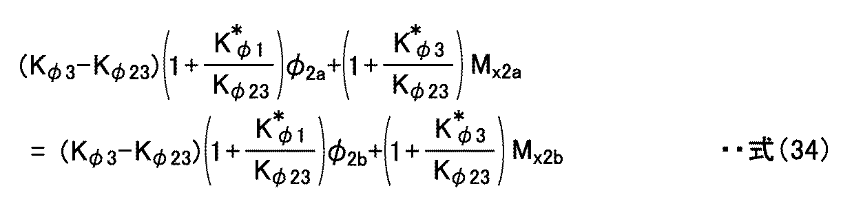
この式(34)に、下記の式(35)に示す如くロール剛性係数Kφ1,Kφ2,Kφ3及びフレーム捩じり剛性係数Kφ12,Kφ23により定義した車両固有のロール剛性係数Kφ13を更新し、係数Kφ13について整理すると、下記の式(36)が得られる。


すなわち、ロール剛性係数Kφ13は、上記単体車両の場合(式(7))と同様、車高調整開始時及び終了時におけるロールモーメントMx2a及びMx2bとロール角φ2a及びφ2bとから求めることができる。
また、上記の式(33)は、ロール剛性係数Kφ13を用いて下記の式(37)で表すことができる。

上記の式(37)の左辺は同一の積載条件下においては変化せず一定であるため、図19に示した車両1においても、上記の式(14)に示した車高調整終了時のロール角φ2b及びロールモーメントMx2bと、車高調整非実行時のロールモーメント(trd(FLes-FRes))及びロール角φ2esとにロール剛性係数Kφ13を用いた等号関係が成立する。
従って、処理部13は、車高調整非実行時のロール角φ2esを、第1の時点及び第2の時点におけるサスペンション3L及び3RによるロールモーメントMx2a,Mx2bと、第1の時点及び第2の時点でのロール角φ2a,φ2bと、トレッド長trdと、上記の式(17)中の1次係数aとを用いて算出し、補正ロール角φ2off、及び補正後ロール角φAMDを算出することができる。すなわち、上述の第1の推定方法によって、車高調整非実行時のロール角φ2esを推定して、補正ロール角φ2off、及び補正後ロール角φAMDを算出することができる。
また、上記第1の推定方法と同様の理由から、1つの時点でのロールモーメントMx2及びロール角φ2と、これらの検出値を取得する前に記憶されたロール剛性係数Kφ13def或いはKφ13newとを用いてロール角φ2esを算出することも可能である。すなわち、上述の第2の推定方法によっても、車高調整非実行時のロール角φ2esを推定して、補正ロール角φ2off、及び補正後ロール角φAMDを算出することができる。
従って、処理部13は、単体車両の場合と同様の処理を実行することによって、補正後ロール角φAMDを算出することができる。
以上、本発明者によってなされた発明を適用した実施形態について説明したが、この実施形態による本発明の開示の一部をなす論述及び図面により本発明は限定されることはない。すなわち、この実施形態に基づいて当業者等によりなされる他の実施形態、実施例及び運用技術等は全て本発明の範疇に含まれることは勿論である。
例えば、処理例[2]において、ステップS607~S609,S613の1つ又は複数を省略してもよく、ステップS804~S806,S809の1つ又は複数を省略してもよい。
また、加速度発生フラグF1がオフか否かの判定(検出加速度が所定加速度未満であるか否かの判定)は、ロール剛性係数Kφ13の更新処理前や補正ロール角φ2offの更新処理前の任意のタイミングで行えばよい。
また、ロール角推定装置10は、車高調整非実行時のロール角φ2esを算出する度に、算出したロール角φ2esを運転者に対して視認可能な状態で報知してもよい。例えば、車室内の運転席前方に表示部を設け、算出したロール角φ2esを所定の表示態様で表示部に表示してもよい。所定の表示態様は、ロール角φ2esの数値表示であってもよく、ロール角φ2esの数値に応じて状態が変化(例えば伸縮、移動、変色等)するインジケータなどであってもよい。
本発明は、エアサスペンションを備えた車両に広く適用可能である。
1:車両
3L,3R,5L,5R,7L,7R:サスペンション
10:ロール角推定装置
11L,11R:変位検出部
12L,12R:圧力測定部
13:処理部
14:加速度測定部
20:横転危険度判定装置
21:ロール角・ロール角速度検出部
22:横転危険度判定部
30:車高調整装置
Z,ZL,ZLa,ZLb,ZR,ZRa,ZRb:エアバネ変位
P,PL,PLa,PLb,PR,PRa,PRb:エアバネ内圧
φ:検出ロール角
φ2a:ロール角(車高調整開始時)
φ2b:ロール角(車高調整中又は車高調整終了時)
φ2es:車高調整非実行時のロール角
φ2off:補正ロール角
φAMD:補正後ロール角
Kφ1,Kφ2,Kφ3,Kφ13,Kφ13new,Kφ13def:ロール剛性係数
Kφ12,Kφ23:フレーム捩じり剛性係数
Mx2:サスペンションによるロールモーメント
Mx2a:車高調整開始時のサスペンションによるロールモーメント
Mx2b:車高調整終了時のサスペンションによるロールモーメント
Mx:荷物偏積によるロールモーメント
CF1~CF7:荷重-変位特性
EXP1~EXP7:線形近似式
a:1次係数
b:定数
SGS:車高調整開始信号
SGF:車高調整終了信号
AP:エア
3L,3R,5L,5R,7L,7R:サスペンション
10:ロール角推定装置
11L,11R:変位検出部
12L,12R:圧力測定部
13:処理部
14:加速度測定部
20:横転危険度判定装置
21:ロール角・ロール角速度検出部
22:横転危険度判定部
30:車高調整装置
Z,ZL,ZLa,ZLb,ZR,ZRa,ZRb:エアバネ変位
P,PL,PLa,PLb,PR,PRa,PRb:エアバネ内圧
φ:検出ロール角
φ2a:ロール角(車高調整開始時)
φ2b:ロール角(車高調整中又は車高調整終了時)
φ2es:車高調整非実行時のロール角
φ2off:補正ロール角
φAMD:補正後ロール角
Kφ1,Kφ2,Kφ3,Kφ13,Kφ13new,Kφ13def:ロール剛性係数
Kφ12,Kφ23:フレーム捩じり剛性係数
Mx2:サスペンションによるロールモーメント
Mx2a:車高調整開始時のサスペンションによるロールモーメント
Mx2b:車高調整終了時のサスペンションによるロールモーメント
Mx:荷物偏積によるロールモーメント
CF1~CF7:荷重-変位特性
EXP1~EXP7:線形近似式
a:1次係数
b:定数
SGS:車高調整開始信号
SGF:車高調整終了信号
AP:エア
Claims (6)
- 車両に発生する加速度が予め設定された所定加速度以上である場合、更新禁止状態であると判定し、所定加速度未満である場合、更新禁止状態ではないと判定する第1ステップと、
同一の荷重-変位特性及び荷重-内圧特性を有し、且つ自動車高調整の対象となる一部の左右サスペンションの自動車高調整開始時の一定時間前から終了時の一定時間後までのうち前記自動車高調整の少なくとも一部が間に介在する任意の異なる第1及び第2の時点の各々において測定された第1及び第2の変位並びに第1及び第2の内圧値から、第1及び第2のロール角と前記左右サスペンションによる第1及び第2のロールモーメントとをそれぞれ算出し、算出した第1及び第2のロール角並びに第1及び第2のロールモーメントから、前記サスペンションを装着した車両固有のロール剛性係数を算出し、前記サスペンションが示し得る内圧値をパラメータとして予め求めた複数個の荷重-変位特性のうち、前記左右サスペンションの測定内圧平均値に対応する荷重-変位特性を、前記自動車高調整が行われなかった場合の前記左右サスペンションに共通の荷重-変位特性として選択し、前記算出した第2のロール角及び第2のロールモーメントと、前記算出したロール剛性係数と、前記選択した荷重-変位特性とに基づき、前記自動車高調整が行われなかった場合のロール角を求める第2ステップと、
前記第2ステップで求めた前記自動車高調整が行われなかった場合のロール角から前記第2ステップで算出した前記第2のロール角を減算することにより、前記自動車高調整による補正ロール角を求める第3ステップと、
前記第1ステップで前記更新禁止状態ではないと判定した場合、前記第3ステップで求めた補正ロール角を更新して記憶し、前記第1ステップで前記更新禁止状態であると判定した場合、補正ロール角の更新を実行しない第4ステップと、を備えた
ことを特徴とする車両のロール角推定方法。 - 車両に発生する加速度が予め設定された所定加速度以上である場合、更新禁止状態であると判定し、所定加速度未満である場合、更新禁止状態ではないと判定する第1ステップと、
同一の荷重-変位特性及び荷重-内圧特性を有し、且つ自動車高調整の対象となる一部の左右サスペンションの任意の時点において測定された変位及び内圧値から、ロール角と前記左右サスペンションによるロールモーメントとをそれぞれ算出し、前記サスペンションが示し得る内圧値をパラメータとして予め求めた複数個の荷重-変位特性のうち、前記左右サスペンションの測定内圧平均値に対応する荷重-変位特性を、前記自動車高調整が行われなかった場合の前記左右サスペンションに共通の荷重-変位特性として選択し、前記算出したロール角及びロールモーメントと、前記選択した荷重-変位特性と、前記サスペンションを装着した車両固有の値として前記変位及び内圧値の測定前に記憶されたロール剛性係数とに基づき、前記自動車高調整が行われなかった場合のロール角を求める第2ステップと、
前記第2ステップで求めた前記自動車高調整が行われなかった場合のロール角から前記第2ステップで算出したロール角を減算することにより、前記自動車高調整による補正ロール角を求める第3ステップと、
前記第1ステップで前記更新禁止状態ではないと判定した場合、前記第3ステップで求めた補正ロール角を更新して記憶し、前記第1ステップで前記更新禁止状態であると判定した場合、補正ロール角の更新を実行しない第4ステップと、を備えた
ことを特徴とする車両のロール角推定方法。 - 車両に発生する加速度が予め設定された所定加速度以上である場合、更新禁止状態であると判定し、所定加速度未満である場合、更新禁止状態ではないと判定する第1ステップと、
同一の荷重-変位特性及び荷重-内圧特性を有し、且つ自動車高調整の対象となる一部の左右サスペンションの自動車高調整開始時の一定時間前から終了時の一定時間後までのうち前記自動車高調整の少なくとも一部が間に介在する任意の異なる第1及び第2の時点の各々において測定された第1及び第2の変位並びに第1及び第2の内圧値から、第1及び第2のロール角と前記左右サスペンションによる第1及び第2のロールモーメントとをそれぞれ算出し、前記第1及び第2のロール角並びに前記第1及び第2のロールモーメントから、前記サスペンションを装着した車両固有のロール剛性係数を算出する第2ステップと、
前記第1ステップで前記更新禁止状態ではないと判定したとき、前記第2ステップで算出したロール剛性係数を更新して記憶し、前記第1ステップで前記更新禁止状態であると判定したとき、前記第2ステップで算出したロール剛性係数を更新して記憶しない第3ステップと、
前記第3ステップでロール剛性係数を更新して記憶した後の任意の時点において測定された前記左右サスペンションの変位及び内圧値から、ロール角と前記左右サスペンションによるロールモーメントとをそれぞれ算出し、前記サスペンションが示し得る内圧値をパラメータとして予め求めた複数個の荷重-変位特性のうち、前記左右サスペンションの測定内圧平均値に対応する荷重-変位特性を、前記自動車高調整が行われなかった場合の前記左右サスペンションに共通の荷重-変位特性として選択し、前記算出したロール角及びロールモーメントと、前記選択した荷重-変位特性と、前記第3ステップで記憶した最新のロール剛性係数とに基づき、前記自動車高調整が行われなかった場合のロール角を求める第4ステップと、を備える
ことを特徴とする車両のロール角推定方法。 - 車両に発生する加速度が予め設定された所定加速度以上である場合、更新禁止状態であると判定し、所定加速度未満である場合、更新禁止状態ではないと判定する判定部と、
同一の荷重-変位特性及び荷重-内圧特性を有し、且つ自動車高調整の対象となる一部の左右サスペンションの自動車高調整開始時の一定時間前から終了時の一定時間後までのうち前記自動車高調整の少なくとも一部が間に介在する任意の異なる第1及び第2の時点の各々において測定された第1及び第2の変位並びに第1及び第2の内圧値から、第1及び第2のロール角と前記左右サスペンションによる第1及び第2のロールモーメントとをそれぞれ算出し、算出した第1及び第2のロール角並びに第1及び第2のロールモーメントから、前記サスペンションを装着した車両固有のロール剛性係数を算出し、前記サスペンションが示し得る内圧値をパラメータとして予め求めた複数個の荷重-変位特性のうち、前記左右サスペンションの測定内圧平均値に対応する荷重-変位特性を、前記自動車高調整が行われなかった場合の前記左右サスペンションに共通の荷重-変位特性として選択し、前記算出した第2のロール角及び第2のロールモーメントと、前記算出したロール剛性係数と、前記選択した荷重-変位特性とに基づき、前記自動車高調整が行われなかった場合のロール角を求めるロール角決定部と、
前記ロール角決定部が求めた前記自動車高調整が行われなかった場合のロール角から前記ロール角決定部が算出した前記第2のロール角を減算することにより、前記自動車高調整による補正ロール角を求める補正ロール角決定部と、
前記更新禁止状態ではないと前記判定部が判定した場合、前記補正ロール角決定部が求めた補正ロール角を記憶部に更新して記憶し、前記更新禁止状態であると前記判定部が判定した場合、補正ロール角の更新を実行しない記憶制御部と、を備えた
ことを特徴とする車両のロール角推定装置。 - 車両に発生する加速度が予め設定された所定加速度以上である場合、更新禁止状態であると判定し、所定加速度未満である場合、更新禁止状態ではないと判定する判定部と、
同一の荷重-変位特性及び荷重-内圧特性を有し、且つ自動車高調整の対象となる一部の左右サスペンションの任意の時点において測定された変位及び内圧値から、ロール角と前記左右サスペンションによるロールモーメントとをそれぞれ算出し、前記サスペンションが示し得る内圧値をパラメータとして予め求めた複数個の荷重-変位特性のうち、前記左右サスペンションの測定内圧平均値に対応する荷重-変位特性を、前記自動車高調整が行われなかった場合の前記左右サスペンションに共通の荷重-変位特性として選択し、前記算出したロール角及びロールモーメントと、前記選択した荷重-変位特性と、前記サスペンションを装着した車両固有の値として前記変位及び内圧値の測定前に記憶されたロール剛性係数とに基づき、前記自動車高調整が行われなかった場合のロール角を求めるロール角決定部と、
前記ロール角決定部が求めた前記自動車高調整が行われなかった場合のロール角から前記ロール角決定部が算出したロール角を減算することにより、前記自動車高調整による補正ロール角を求める補正ロール角決定部と、
前記更新禁止状態ではないと前記判定部が判定した場合、前記補正ロール角決定部が求めた補正ロール角を記憶部に更新して記憶し、前記更新禁止状態であると前記判定部が判定した場合、補正ロール角の更新を実行しない記憶制御部と、を備えた
ことを特徴とする車両のロール角推定装置。 - 車両に発生する加速度が予め設定された所定加速度以上である場合、更新禁止状態であると判定し、所定加速度未満である場合、更新禁止状態ではないと判定する判定部と、
同一の荷重-変位特性及び荷重-内圧特性を有し、且つ自動車高調整の対象となる一部の左右サスペンションの自動車高調整開始時の一定時間前から終了時の一定時間後までのうち前記自動車高調整の少なくとも一部が間に介在する任意の異なる第1及び第2の時点の各々において測定された第1及び第2の変位並びに第1及び第2の内圧値から、第1及び第2のロール角と前記左右サスペンションによる第1及び第2のロールモーメントとをそれぞれ算出し、前記第1及び第2のロール角並びに前記第1及び第2のロールモーメントから、前記サスペンションを装着した車両固有のロール剛性係数を算出するロール剛性係数算出部と、
前記第1ステップで前記更新禁止状態ではないと判定したとき、前記第2ステップで算出したロール剛性係数を更新して記憶し、前記第1ステップで前記更新禁止状態であると判定したとき、前記第2ステップで算出したロール剛性係数を更新して記憶しない記憶制御部と、
前記第3ステップでロール剛性係数を更新して記憶した後の任意の時点において測定された前記左右サスペンションの変位及び内圧値から、ロール角と前記左右サスペンションによるロールモーメントとをそれぞれ算出し、前記サスペンションが示し得る内圧値をパラメータとして予め求めた複数個の荷重-変位特性のうち、前記左右サスペンションの測定内圧平均値に対応する荷重-変位特性を、前記自動車高調整が行われなかった場合の前記左右サスペンションに共通の荷重-変位特性として選択し、前記算出したロール角及びロールモーメントと、前記選択した荷重-変位特性と、前記第3ステップで記憶した最新のロール剛性係数とに基づき、前記自動車高調整が行われなかった場合のロール角を求めるロール角決定部と、を備える
ことを特徴とする車両のロール角推定装置。
Applications Claiming Priority (2)
| Application Number | Priority Date | Filing Date | Title |
|---|---|---|---|
| JP2011-222872 | 2011-10-07 | ||
| JP2011222872A JP5910918B2 (ja) | 2011-10-07 | 2011-10-07 | 車両のロール角推定方法及び装置 |
Publications (1)
| Publication Number | Publication Date |
|---|---|
| WO2013051690A1 true WO2013051690A1 (ja) | 2013-04-11 |
Family
ID=48043843
Family Applications (1)
| Application Number | Title | Priority Date | Filing Date |
|---|---|---|---|
| PCT/JP2012/075926 Ceased WO2013051690A1 (ja) | 2011-10-07 | 2012-10-05 | 車両のロール角推定方法及び装置 |
Country Status (2)
| Country | Link |
|---|---|
| JP (1) | JP5910918B2 (ja) |
| WO (1) | WO2013051690A1 (ja) |
Cited By (1)
| Publication number | Priority date | Publication date | Assignee | Title |
|---|---|---|---|---|
| US10392122B2 (en) | 2015-01-30 | 2019-08-27 | Airbus Operations Gmbh | Inerting system and method for an aircraft using exhaust air |
Families Citing this family (3)
| Publication number | Priority date | Publication date | Assignee | Title |
|---|---|---|---|---|
| JP6476590B2 (ja) * | 2014-05-19 | 2019-03-06 | いすゞ自動車株式会社 | 車高調整システムの制御装置 |
| JP6443719B2 (ja) * | 2014-07-17 | 2018-12-26 | いすゞ自動車株式会社 | 車両のロール角推定装置 |
| JP6443720B2 (ja) * | 2014-07-17 | 2018-12-26 | いすゞ自動車株式会社 | 車両のロール角推定装置 |
Citations (4)
| Publication number | Priority date | Publication date | Assignee | Title |
|---|---|---|---|---|
| WO2008149607A1 (ja) * | 2007-06-08 | 2008-12-11 | Isuzu Motors Limited | 車両の横転防止装置 |
| JP2008307942A (ja) * | 2007-06-12 | 2008-12-25 | Isuzu Motors Ltd | 車両のロール角推定方法及び装置 |
| JP2009227265A (ja) * | 2007-12-07 | 2009-10-08 | Isuzu Motors Ltd | 車両のロール角推定方法及び装置 |
| JP2011240792A (ja) * | 2010-05-18 | 2011-12-01 | Isuzu Motors Ltd | 車両のエアサスペンションのバネ特性の補正方法及び補正装置 |
-
2011
- 2011-10-07 JP JP2011222872A patent/JP5910918B2/ja not_active Expired - Fee Related
-
2012
- 2012-10-05 WO PCT/JP2012/075926 patent/WO2013051690A1/ja not_active Ceased
Patent Citations (4)
| Publication number | Priority date | Publication date | Assignee | Title |
|---|---|---|---|---|
| WO2008149607A1 (ja) * | 2007-06-08 | 2008-12-11 | Isuzu Motors Limited | 車両の横転防止装置 |
| JP2008307942A (ja) * | 2007-06-12 | 2008-12-25 | Isuzu Motors Ltd | 車両のロール角推定方法及び装置 |
| JP2009227265A (ja) * | 2007-12-07 | 2009-10-08 | Isuzu Motors Ltd | 車両のロール角推定方法及び装置 |
| JP2011240792A (ja) * | 2010-05-18 | 2011-12-01 | Isuzu Motors Ltd | 車両のエアサスペンションのバネ特性の補正方法及び補正装置 |
Cited By (1)
| Publication number | Priority date | Publication date | Assignee | Title |
|---|---|---|---|---|
| US10392122B2 (en) | 2015-01-30 | 2019-08-27 | Airbus Operations Gmbh | Inerting system and method for an aircraft using exhaust air |
Also Published As
| Publication number | Publication date |
|---|---|
| JP5910918B2 (ja) | 2016-04-27 |
| JP2013082296A (ja) | 2013-05-09 |
Similar Documents
| Publication | Publication Date | Title |
|---|---|---|
| US9823111B2 (en) | Method and device for estimating loading state of vehicle | |
| US20070078581A1 (en) | Vehicle dynamics control system adapted to the load condition of a vehicle | |
| US20100036597A1 (en) | Method and device for estimating the height of the center of gravity of a vehicle | |
| KR20200088396A (ko) | 차량, 차량 운동 상태 추정 장치 및 차량 운동 상태 추정 방법 | |
| JP5811260B2 (ja) | 車高推定装置および車高推定方法 | |
| JP5176918B2 (ja) | 車両のロール角推定方法及び装置 | |
| KR20110056397A (ko) | 차량의 중심을 검출하기 위한 방법 및 장치 | |
| JP5910918B2 (ja) | 車両のロール角推定方法及び装置 | |
| JP5472813B2 (ja) | 車両のエアサスペンションのバネ特性の補正方法及び補正装置 | |
| CN100554016C (zh) | 与车辆装载状况相匹配的行驶动力学调节系统 | |
| JP6623782B2 (ja) | 車両の重心位置推定装置および重心位置推定方法 | |
| JP6623783B2 (ja) | 車両の重心位置推定装置および重心位置推定方法 | |
| CN109305007B (zh) | 悬架控制系统和车辆 | |
| JP5910914B2 (ja) | 車両のロール角推定方法及び装置 | |
| JP5910915B2 (ja) | 車両のロール角推定方法及び装置 | |
| JP5910916B2 (ja) | 車両のロール角推定方法及び装置 | |
| JP5910917B2 (ja) | 車両のロール角推定方法及び装置 | |
| JP2020185940A (ja) | 車両運動状態推定装置、および、車両運動状態推定方法 | |
| GB2580035A (en) | Vehicle stability apparatus and method | |
| JP6443720B2 (ja) | 車両のロール角推定装置 | |
| KR101735729B1 (ko) | 휠 속도를 이용한 차량 질량 추정 장치 및 그 방법 | |
| JP6443719B2 (ja) | 車両のロール角推定装置 | |
| JP6614481B2 (ja) | 車両の横転危険度判定システム |
Legal Events
| Date | Code | Title | Description |
|---|---|---|---|
| 121 | Ep: the epo has been informed by wipo that ep was designated in this application |
Ref document number: 12838535 Country of ref document: EP Kind code of ref document: A1 |
|
| NENP | Non-entry into the national phase |
Ref country code: DE |
|
| 122 | Ep: pct application non-entry in european phase |
Ref document number: 12838535 Country of ref document: EP Kind code of ref document: A1 |