WO2013046797A1 - 表示装置及びテレビ受信装置 - Google Patents
表示装置及びテレビ受信装置 Download PDFInfo
- Publication number
- WO2013046797A1 WO2013046797A1 PCT/JP2012/063010 JP2012063010W WO2013046797A1 WO 2013046797 A1 WO2013046797 A1 WO 2013046797A1 JP 2012063010 W JP2012063010 W JP 2012063010W WO 2013046797 A1 WO2013046797 A1 WO 2013046797A1
- Authority
- WO
- WIPO (PCT)
- Prior art keywords
- back cabinet
- cover
- opening
- cabinet body
- protrusion
- Prior art date
- Legal status (The legal status is an assumption and is not a legal conclusion. Google has not performed a legal analysis and makes no representation as to the accuracy of the status listed.)
- Ceased
Links
Images



























Classifications
-
- G—PHYSICS
- G02—OPTICS
- G02F—OPTICAL DEVICES OR ARRANGEMENTS FOR THE CONTROL OF LIGHT BY MODIFICATION OF THE OPTICAL PROPERTIES OF THE MEDIA OF THE ELEMENTS INVOLVED THEREIN; NON-LINEAR OPTICS; FREQUENCY-CHANGING OF LIGHT; OPTICAL LOGIC ELEMENTS; OPTICAL ANALOGUE/DIGITAL CONVERTERS
- G02F1/00—Devices or arrangements for the control of the intensity, colour, phase, polarisation or direction of light arriving from an independent light source, e.g. switching, gating or modulating; Non-linear optics
- G02F1/01—Devices or arrangements for the control of the intensity, colour, phase, polarisation or direction of light arriving from an independent light source, e.g. switching, gating or modulating; Non-linear optics for the control of the intensity, phase, polarisation or colour
- G02F1/13—Devices or arrangements for the control of the intensity, colour, phase, polarisation or direction of light arriving from an independent light source, e.g. switching, gating or modulating; Non-linear optics for the control of the intensity, phase, polarisation or colour based on liquid crystals, e.g. single liquid crystal display cells
- G02F1/133—Constructional arrangements; Operation of liquid crystal cells; Circuit arrangements
- G02F1/1333—Constructional arrangements; Manufacturing methods
- G02F1/133308—Support structures for LCD panels, e.g. frames or bezels
- G02F1/133314—Back frames
-
- H—ELECTRICITY
- H04—ELECTRIC COMMUNICATION TECHNIQUE
- H04N—PICTORIAL COMMUNICATION, e.g. TELEVISION
- H04N5/00—Details of television systems
- H04N5/64—Constructional details of receivers, e.g. cabinets or dust covers
-
- G—PHYSICS
- G02—OPTICS
- G02F—OPTICAL DEVICES OR ARRANGEMENTS FOR THE CONTROL OF LIGHT BY MODIFICATION OF THE OPTICAL PROPERTIES OF THE MEDIA OF THE ELEMENTS INVOLVED THEREIN; NON-LINEAR OPTICS; FREQUENCY-CHANGING OF LIGHT; OPTICAL LOGIC ELEMENTS; OPTICAL ANALOGUE/DIGITAL CONVERTERS
- G02F2201/00—Constructional arrangements not provided for in groups G02F1/00 - G02F7/00
- G02F2201/50—Protective arrangements
Definitions
- the present invention relates to a display device such as a liquid crystal television or a plasma television and a television receiver.
- a thin display device such as a thin television has a housing made up of a front cabinet and a back cabinet that cover a display portion.
- the back cabinet may be divided into a plurality of members in order to improve transportability and facilitate assembly (see, for example, Patent Documents 1 and 2).
- Patent Documents 1 and 2 By the way, since the thin display device tends to be large, when molding the casing, larger molding machines are required one after another.
- the casing is divided into a plurality of members, and each member of the divided casing is molded by an existing molding machine.
- An object of the present invention is to provide a display device and a television receiver that can ensure safety while dividing a housing.
- a display device includes a display unit having a display surface on the front side, a front cabinet that surrounds a peripheral portion of the display unit, and a back cabinet that covers a rear side of the display unit, and the back cabinet has an opening.
- the lid is made of a material different from the material constituting the back cabinet body. It is characterized by that.
- the display device includes a display unit, a front cabinet, and a back cabinet.
- the display unit has a display surface on the front side.
- the front cabinet surrounds the periphery of the display unit.
- the back cabinet covers the rear side of the display unit.
- the back cabinet includes a back cabinet body and a lid.
- the back cabinet body is provided with an opening.
- the lid is attached to the back cabinet body so as to close the opening of the back cabinet body.
- the back cabinet body and the lid are made of different materials. If both the back cabinet body and the lid are made of the same material, there is a possibility that the cost will be high. Cost reduction can be achieved by molding one of the back cabinet body and the lid body with a material having a low safety standard. On the other hand, safety is ensured by molding the other of the back cabinet body and the lid body with a material having a high safety standard.
- the display device is characterized in that the lid is made of a material having lower flame retardancy than the back cabinet body.
- the lid is made of a material that is less flame retardant than the back cabinet body.
- the cost can be reduced by making the material of the lid less flame-retardant than the material of the back cabinet body.
- the safety of fire protection is ensured by molding the back cabinet body with a highly flame-retardant material.
- the display device includes a circuit board fixed between the display unit and the back cabinet, and the opening is provided in a region of the back cabinet body that does not face the circuit board. .
- the display device includes a circuit board.
- the circuit board is fixed between the display unit and the back cabinet.
- the opening of the back cabinet body is provided in a region that does not face the circuit board.
- the circuit board is a heating element that may become high temperature when a high-voltage current is applied.
- the lid is a member that covers an opening provided in a region not facing the circuit board in the back cabinet body. Therefore, even when the lid is formed of a material having low flame retardancy, no particular problem is caused in terms of fire protection.
- the opening is provided in a region facing the display unit in the back cabinet body, and an inner cylinder and the inner cylinder are provided on a front side surface of the periphery of the opening in the back cabinet body.
- the outer cylinder which surrounds is provided around.
- the opening is provided in a region of the back cabinet body facing the display unit.
- An inner cylinder and an outer cylinder surrounding the inner cylinder are provided around the front side surface of the periphery of the opening in the back cabinet body.
- the front side surface of the periphery of the opening is the inner surface of the display device.
- the outer cylinder provided on the inner surface has a function as an enclosure that separates the space in the opening from the inside of the display device having the possibility of ignition.
- the inner cylinder contained inside the outer cylinder has a function as a further enclosure.
- the display device is characterized in that a plurality of locking claws that are locked to a peripheral wall end of the inner cylinder are provided on a peripheral portion of the front side surface of the lid.
- a plurality of locking claws that are locked to the peripheral wall end of the inner cylinder are provided on the peripheral edge of the front side surface of the lid that covers the opening of the back cabinet body.
- the locking claw provided on the lid is locked to the peripheral wall end of the inner cylinder provided on the back cabinet body, so that the lid is fixed to the back cabinet body around the opening and the opening is closed. .
- the locking claw includes a base portion provided on the front side surface of the lid body, and reinforcing ribs provided on corner portions formed by the inner side surface of the base portion and the front side surface of the lid body. It is characterized by having.
- the locking claw has a base portion and a reinforcing rib.
- the base is provided on the front side surface of the lid.
- the reinforcing rib is provided at a corner portion formed by the inner side surface of the base portion and the front side surface of the lid.
- the reinforcing rib has a function of reinforcing the base of the locking claw and can increase the strength of the locking claw.
- the opening surface of the outer cylinder, the opening, and the lid body each have a rectangular shape, and the lid body is positioned with respect to the back cabinet body on one long side surface of the lid body.
- a positioning projection is provided, and an opening in which the positioning projection can be loosely inserted is provided on a circumferential wall of the outer cylinder facing the positioning projection, and an inner surface of the circumferential wall.
- a guide protrusion that guides the positioning protrusion to the opening is provided around the opening of the guide protrusion, and a recess is provided on a rear side surface of the guide protrusion. It is provided in the periphery of the said opening part including the inner edge of a protrusion.
- the opening surface of the outer cylinder, the opening portion, and the lid body each have a rectangular shape.
- a positioning projection for positioning the lid relative to the back cabinet body is provided on one long side surface of the lid.
- An opening through which the positioning protrusion can be loosely inserted is provided in a circumferential wall in the longitudinal direction of the outer cylinder facing the positioning protrusion.
- a guide projection that guides the positioning projection to the opening is provided on the inner surface of the circumferential wall of the outer cylinder in the longitudinal direction.
- a recess is provided on the rear side surface of the guide protrusion.
- the positioning protrusion is inserted into the opening of the outer cylinder provided at the periphery of the opening by advancing the positioning protrusion of the lid along the depression of the guide protrusion provided around the opening of the outer cylinder. be able to. Thereby, when attaching a cover body to a back cabinet main body, the positioning operation
- a television receiver includes the display device described above and a receiver that receives a television broadcast, and the display device displays a video of the television broadcast received by the receiver.
- the television receiver includes the above-described display device and a receiver that receives a television broadcast.
- the display device displays a television broadcast image received by the receiving unit. Therefore, even when the back cabinet of the television receiver is divided, safety such as fire protection can be ensured.
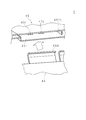
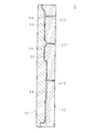
- FIG. 31B is a cross-sectional view of the back cabinet body and the cover cut along the cutting line II in FIG. 31A. It is the plane enlarged view which looked at the example of the back cabinet main body and cover after an assembly seen from the rear side of the television receiver. It is the perspective view which showed the hole provided in the edge part of the opening part upper part of a back cabinet main body from the rear left diagonal bottom of a television receiver.
- the television receiver according to the present embodiment includes, for example, a flat panel such as a liquid crystal display, a plasma display, an organic EL (Electro Luminescence) display, and an SED (Surface-conduction Electron-emitter Display).
- a flat panel such as a liquid crystal display, a plasma display, an organic EL (Electro Luminescence) display, and an SED (Surface-conduction Electron-emitter Display).
- a television receiver provided with a liquid crystal display will be described. Note that the present invention is not limited to the following embodiments.
- FIG. 1 is a schematic perspective view of the television receiver 1.
- the viewer side is the front side from the display surface 21, and the back side is the rear side from the opposite display surface 21.
- the display surface 21 is a horizontally long substantially rectangular shape, and the right side in the long side direction of the display surface 21 is the right and the left side in the long side direction of the display surface 21 is the left from the viewer toward the display surface 21.
- the left and right are opposite to the left and right of the front side.
- FIG. 1 shows the television receiver 1 from diagonally upward on the front side.
- the television receiver 1 includes a display unit 2, a front cabinet 3, a back cabinet 4, a receiving unit T, a power supply board (circuit board) P, a drive board (circuit board) D, and a stand S.
- the display unit 2 is a liquid crystal panel module, and includes a liquid crystal panel and a backlight.
- the liquid crystal panel has a display surface 21 and displays an image on the display surface 21.
- the backlight irradiates light from behind the liquid crystal panel.
- the display unit 2 is surrounded by a front side peripheral portion and an outer peripheral surface by a front side front cabinet 3.
- the front cabinet 3 has a horizontally-long rectangular opening 31a, and the display surface 21 of the display unit 2 is exposed from the opening 31a.
- the back cabinet 4 on the rear side of the television receiver 1 has a flat plate shape and covers the display unit 2 and a part of the front cabinet 3 from the rear side of the television receiver 1.
- the receiving unit T, the power supply substrate P, and the drive substrate D are located between the display unit 2 and the back cabinet 4 and are fixed to the display unit 2 by, for example, screwing.
- the stand S supports the display unit 2, the front cabinet 3, the back cabinet 4, the receiving unit T, the power supply substrate P, and the drive substrate D in an upright state.
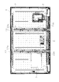
- FIG. 2 is a plan view showing an example of the assembled display unit 2 and front cabinet 3 from the rear side of the television receiver 1.
- FIG. 2 shows a state in which the television receiver 1 from which the back cabinet 4 and the stand S are removed is viewed from the rear side.
- two support plates 22, 23 extending in the vertical direction are fixed, for example, with screws.
- the support plates 22 and 23 are provided with brackets 22a, 22b, 23a and 23b for screwing screws, respectively.
- the support plates 22 and 23 and the brackets 22a, 22b, 23a, and 23b are used.
- the receiving unit T receives a video signal related to television broadcasting.
- the power supply board P supplies power to each component of the television receiver 1.
- the drive substrate D includes, for example, a panel drive substrate and a backlight drive substrate.
- the panel drive board performs predetermined signal processing on the video signal related to the television broadcast received by the receiving unit T, and outputs the video signal after the signal processing to the liquid crystal panel.
- the backlight driving substrate drives the backlight. Note that when there is a flammable material in the vicinity of the power supply substrate P and the drive substrate D, the possibility of fire from the ignitable material is not zero due to the high heat generated by applying a high voltage to the power supply substrate P and the drive substrate D.
- the power supply substrate P and the drive substrate D are an example of a heating element included in the television receiver 1.
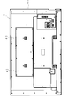
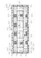
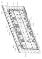
- FIG. 3 is a plan view of an example of the back cabinet 4 as viewed from the rear side of the television receiver 1.
- FIG. 4 is a schematic perspective view showing an example of the back cabinet 4.
- FIG. 4 shows the back cabinet 4 from the upper left of the front side of the television receiver 1.
- the back cabinet 4 is substantially rectangular and substantially flat, and is made of, for example, synthetic resin.
- the outer peripheral edge of the back cabinet 4 is provided with a plurality of screw holes, and the back cabinet 4 is fixed to the display unit 2 or the front cabinet 3 with screws.
- the back cabinet 4 consists of two members, and FIGS. 3 and 4 show the state of the back cabinet 4 assembled using the two members.
- the back cabinet 4 includes a back cabinet body 41 and a cover (lid body) 42.
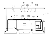
- FIG. 5A is a plan view of the back cabinet body 41 as viewed from the rear side of the television receiver 1.
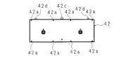
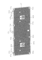
- FIG. 5B is a plan view of the cover 42 as viewed from the rear side of the television receiver 1.
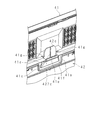
- Plate-shaped protrusions (positioning protrusions) 42c and 42d are provided so as to protrude upward on one long side end face of the cover 42.
- the front side of the back cabinet body 41 and the cover 42 is the front.
- the front side of the back cabinet body 41 and the cover 42 is the rear side of the television receiver 1, and the back side of the back cabinet body 41 and the cover 42 is the front side of the television receiver 1.
- FIG. 6 is a schematic perspective view showing an example of the back cabinet body 41.
- FIG. 6 shows the back cabinet body 41 from the rear left diagonally lower side of the television receiver 1.
- the back cabinet body 41 is provided with an opening 41a at the upper center.
- the region in which the opening 41 a is provided is a region that does not face the receiving unit T, the power supply substrate P, and the drive substrate D, for example, when the back cabinet 4 is fixed to the display unit 2 or the front cabinet 3.
- the opening 41a has a horizontally long rectangular shape. As shown in FIG. 6, the front surface of the peripheral portion of the opening 41 a falls to the front side (back side) of the television receiver 1 with respect to the back cabinet body 41 around the outside, and the front surface of the peripheral portion of the opening 41 a is It is a shelf 41m having a step.
- FIG. 7 is a plan view of an example of the cover 42 as viewed from the rear side of the television receiver 1.
- FIG. 8 is a plan view of an example of the cover 42 as viewed from the front side of the television receiver 1.
- 9 and 10 are schematic perspective views showing an example of the cover 42.
- FIG. 9 shows the cover 42 from the rear left obliquely lower side of the television receiver 1.
- FIG. 10 shows the cover 42 from diagonally lower left on the front side of the television receiver 1.
- the cover 42 is a separate part that covers the opening 41a of the back cabinet body 41, and is a flat plate-like member that has substantially the same rectangular shape as the opening 41a.
- the thickness of the cover 42 is substantially the same as the level difference at the peripheral edge of the opening 41a shown in FIG. Further, the size of the cover 42 is slightly smaller than the size of the opening 41a. Therefore, when the cover 42 is attached to the back cabinet main body 41, the front side surface (the rear side surface of the television receiver 1) of the back cabinet main body 41 and the cover 42 are on the same plane.
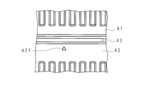
- a groove 43 having a slight width is formed between the outer edge of the shelf 41m and the periphery of the cover 42 at the peripheral edge of the opening 41a of the back cabinet body 41. (See FIG. 3).
- the cover 42 may be thinner than the back cabinet body 41.
- the cover 42 is temporarily fixed or fixed to the back cabinet body 41 with a claw described later. Further, the cover 42 is fixed to the back cabinet main body 41 by screws. Therefore, for example, eight screw through holes 42 a for screwing are formed along the periphery of the cover 42 at the peripheral edge of the cover 42.
- a plate-like protrusion 41b protrudes from the periphery to the inside of the opening 41a at the periphery of the opening 41a of the back cabinet body 41 facing the screw hole 42a (see FIGS. 5A and 6). ).
- a boss (not shown) for screwing the screw inserted through the screw hole 42a stands on the back side (front side of the television receiver device 1). It is installed.
- the protrusion 41b provided at the corner of the opening 41a has a rectangular shape
- the protrusion 41b provided at the long side of the opening 41a has a semicircular shape.
- the screw through hole 42 b is a through hole provided for screwing a screw into the brackets 22 a, 22 b, 23 a, 23 b of the support plates 22, 23 fixed to the display unit 2.
- the UL94 standard is in order of 5VA, 5VB, V-0, V-1, V-2 and the like in descending order of flame retardancy. Defines the grade of HB. It is required to cover, for example, UL94 standard flame retardant V-1 or higher enclosure parts that are the source of ignition or products that may ignite.
- the enclosure separates the housing from the outside in a fireproof, mechanical, and electrical manner. When all the following contents are satisfied, it is certified as an enclosure in the UL94 standard.
- a fireproof enclosure is a piece of equipment that prevents the spread of a flame to a minimum.
- a mechanical enclosure is a piece of equipment that prevents mechanical or other physical hazards. One of the conditions is that a specified clip or the like does not enter the product device.
- An electrical enclosure is any part of equipment that prevents contact with dangerous voltages and currents.
- the back cabinet 4 is also a fireproof, structural and electrical enclosure for the television receiver 1. Therefore, the back cabinet body 41 having a region facing the receiving unit T, the power supply substrate P, and the driving substrate D and the cover 42 corresponding to the region not facing the receiving unit T, the power supply substrate P, and the driving substrate D are difficult. It consists of synthetic resins with different flammability. Specifically, the back cabinet body 41 is made of a synthetic resin of V-1 or higher, and the cover 42 is made of a synthetic resin of HB or lower.
- the cover 42 is arranged around the enclosure and thus is not subject to the UL94 standard restriction regarding the enclosure. Therefore, the grade as a flame retardant can be lowered for the material of the cover 42.
- the back cabinet main body 41 and the cover 42 have a structure for facilitating assembly work.
- the back cabinet body 41 is placed on a horizontal surface with the front side facing up, and the cover 42 is placed near the opening 41 a from above the back cabinet body 41.
- a locking claw 42e or the like which will be described later moves to a normal position while rubbing the front side surface of the back cabinet body 41. 42e and the like may damage the surface of the back cabinet body 41.
- plate-like protrusions (positioning protrusions) 42c, 42d, a protrusion 41b, and a guide protrusion 41f to be described later are provided on the cover 42 and the back cabinet body 41, respectively. Is provided.
- Plate-shaped protrusions 42c and 42d protrude upward from one long side end face on the upper side of the cover 42.
- the plate-like protrusions 42c and 42d are inserted into openings provided in the back cabinet body 41, which will be described later, so that one long side of the cover 42 is one long side of the opening 41a. And easily aligned. At the same time, both short sides of the cover 42 are easily aligned with both short sides of the opening 41a.
- the plate-like protrusion 42c protrudes from the center of the long side end face on the upper side of the cover 42.
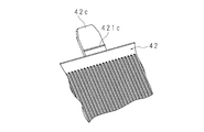
- FIG. 11A is a plan view of the plate-like protrusion 42c provided at the center of the one long side end face on the upper side of the cover 42.
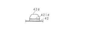
- FIG. 11B is a plan view of the plate-like protrusion 42d provided in the vicinity of the side end of the one long side end surface on the cover 42. 11A and 11B, the cover 42 provided with the plate-like protrusions 42c and 42d is omitted except for a part of the long side.
- FIG. 12 is a perspective view showing an example of the plate-like protrusion 42c.
- FIG. 12 shows the plate-like protrusion 42c from the lower left side of the television receiver 1 obliquely downward.
- the plate-like protrusions 42c and 42d have a flat plate shape and have a shape obtained by cutting out adjacent corners of a rectangle in plan view.
- the plate-like protrusions 42c and 42d are provided so as to protrude from one long side end face on the upper side of the cover 42 so that the cut corners are arranged on the tip side.
- the plate-like protrusion 42c is larger than the plate-like protrusion 42d. Therefore, the width of the plate-like protrusion 42c substantially parallel to the longitudinal direction of the cover 42 and the length of the cover 42 substantially parallel to the short-side direction are both longer than the width and length of the plate-like protrusion 42d.
- One rib 421c, 421d is provided in the width direction at the base of the front side surface (the rear side surface of the television receiver 1) of the plate-like protrusions 42c, 42d.
- the ribs 421c and 421d prevent foreign matters from entering the inside of the television receiver 1 from the opening. It has a function to do. Note that the tips of the plate-like protrusions 42c and 42d may be rounded.
- FIG. 13 is a partial enlarged view of the vicinity of the edge of the opening 41 a on the back side surface of the back cabinet body 41.
- FIG. 13 shows the vicinity of the center of the long side on the upper side of the opening 41 a from the upper left side of the television receiver 1.
- FIG. 13 shows a state where the cover 42 is attached to the back cabinet body 41.
- a rib 422c substantially parallel to the short side direction of the cover 42 is provided at the center of the back side surface of the plate-like protrusion 42c (the front side surface of the television receiver 1).
- the rib 422c has a function of maintaining the strength of the plate-like protrusion 42c appropriately.
- the plate-like protrusion 42d is also provided with a rib 422d similar to the rib 422c (see FIGS. 8 and 10).
- FIG. 14 is a schematic perspective view showing an example of a peripheral portion of the opening 41a in the assembled back cabinet body 41 and cover 42.
- FIG. FIG. 14 is a schematic perspective view of the opening 41 a of the back cabinet body 41 and the peripheral portion of the cover 42 as viewed from the upper left diagonal of the television receiver 1.
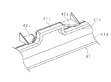
- an inner cylinder 41c and an outer cylinder 41d are erected on the front side of the television receiver 1 at the periphery of the opening 41a (see FIG. 13 and FIG. 13). (See FIG. 14).
- the inner cylinder 41c and the outer cylinder 41d are substantially parallel.
- the region of the front side surface opposite to the back side surface of the back cabinet body 41 where the inner cylinder 41c and the outer cylinder 41d are erected corresponds to the shelf 41m on the periphery of the opening 41a (see FIG. 6).
- the inner cylinder 41c is provided around the periphery of the opening 41a.
- the schematic shape of the opening surface of the inner cylinder 41c is a rectangular shape similar to that of the opening 41a.
- a rectangular or semicircular protrusion 41b is provided to stand up a boss for screwing.
- the inner cylinder 41c is It protrudes from the outer cylinder 41d and inside the opening 41a.
- the outer cylinder 41d surrounds the inner cylinder 41c and is provided outside the inner cylinder 41c.
- the height of the peripheral wall of the outer cylinder 41d is higher than the height of the peripheral wall of the inner cylinder 41c.
- the outer cylinder 41d has an enclosure function for the cover.
- a notch (not shown) is formed to accommodate the support plates 22 and 23 protruding on the rear side.
- FIG. 15 is a partially enlarged view of the vicinity of the edge of the opening 41 a on the front side surface of the back cabinet body 41.
- FIG. 15 shows the vicinity of the center of the long side on the upper side of the opening 41a from the lower left side of the television receiver 1 obliquely.
- FIG. 16 is an explanatory view showing a state in the middle of attaching the cover 42 to the back cabinet body 41.
- FIG. 16 shows the vicinity of the center of the long side on the upper side of the opening 41 a from the lower left diagonal of the television receiver 1.
- an opening 41e is opened at the position of the outer cylinder 41d where the plate-like protrusions 42c and 42d face each other.
- the opening 41e has a horizontally long rectangular shape.
- the long side of the opening 41e facing the plate-like protrusion 42c is longer than the width of the plate-like protrusion 42c, and the short side of the opening 41e facing the plate-like protrusion 42c is longer than the thickness of the plate-like protrusion 42c. . Therefore, the plate-like protrusion 42c can be loosely inserted into the opening 41e.
- the plate-like protrusion 42d is also configured to be loosely inserted in the opposed opening 41e.
- a guide protrusion 41f that receives the plate-like protrusion 42c and guides the received plate-like protrusion 42c to the opening 41e protrudes from the center of the peripheral wall on the upper side of the outer cylinder 41d. Therefore, the inner cylinder 41c protrudes inside the opening 41a at the portion of the protrusion 41b, and the inner cylinder 41c protrudes inside the opening 41a at the portion of the guide protrusion 41f.
- a recess 411f is formed which is recessed toward the front side of the television receiver 1 from the tip of the guide protrusion 41f toward the outer cylinder 41d.
- the outer inner wall of the recess 411f is a peripheral wall of the outer cylinder 41d, and an opening 41e is formed at the approximate center of the outer inner wall of the recess 411f.
- the bottom surface of the recess 411f has a planar shape and is uniformly inclined from the tip end portion of the guide projection 41f toward the outer cylinder 41d. And the bottom side edge part of the hollow 411f has spread toward inner side from the opening 41e.
- the bottom side edge part of the hollow 411f becomes narrow toward the opening 41e from the inner side. That is, the bottom surface of the recess 411f converges toward the opening 41e in order to guide the plate-like protrusion 42c to the opening 41e.
- the bottom surface of the recess 411f has a trapezoidal shape in which the upper base is shorter than the lower base in plan view, and the upper base coincides with the front side end of the television receiver 1 in the opening 41e opened in the outer cylinder 41d.
- the general shape of the recess 411f is similar to a dustpan.
- the protrusions 41b corresponding to the plate-like protrusions 42d are the upper corners of the opening 41a in the back cabinet body 41 so that the guide protrusions 41f are provided on the back cabinet body 41 corresponding to the plate-like protrusions 42c. (See FIG. 5A and FIG. 6).
- the protrusion 41b has the same shape as the guide protrusion 41f and has the same function.
- the protrusion 41b corresponding to the plate-like protrusion 42d is also a protrusion 41b for standing a boss (not shown) to fix the cover 42 to the back cabinet body 41 (FIGS. 5A and 5B). 6).
- two positioning ribs 41g are erected on the front side of the television receiver 1 slightly outside the central opening 41e provided in the outer cylinder 41d of the back cabinet body 41.
- the positioning rib 41g has a function of positioning the cover 42 in the left-right direction with respect to the back cabinet body 41 when the plate-like protrusion 42c is inserted into the opening 41e.
- the locking claw 42e is provided around the periphery of the back side surface of the cover 42 (the front side surface of the television receiver 1).
- four latching claws 42e are provided along the short side of the cover 42, 10 along the upper long side of the cover 42, and 14 along the lower long side of the cover 42, for a total of 32. Yes.
- the distal end portion of the locking claw 42e faces the outside of the cover 42. Therefore, the front ends of the locking claws 42 provided along the long sides of the facing cover 42 and facing each other are in the opposite direction. Similarly, the front ends of the engaging claws 42 provided along the short sides of the facing cover 42 are opposed to each other.
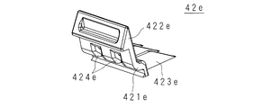
- FIG. 17A and FIG. 17B are perspective views of the locking claw 42e as viewed from the upper right side on the tip end portion 422e side.
- FIG. 17C is a perspective view of the locking claw 42e as viewed from the upper left side opposite to the tip 422e.
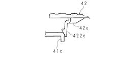
- FIG. 18 is a cross-sectional view showing an example of the locking claw 42e.
- FIG. 18 is a cross-sectional view of the locking claw 42e provided along the long side of the cover 42e, for example, cut along a cutting plane parallel to the normal line and the short side of the cover 42e.
- the locking claw 42e includes a bent plate portion (base portion) 421e, a distal end portion 422e, and a reinforcing rib 423e.
- the bent plate portion 421e of the locking claw 42e provided along the long side of the cover 42e has a rectangular shape when viewed from the short side direction of the cover 42, and when viewed from the long side direction of the cover 42, A crank shape having a stepped portion bent outside the cover 42 is formed.
- two square slits 424e are provided in the inside of the bent plate portion 421e above the bent portion.
- the shape of the slit 424e is not limited to a square shape, and may be a rectangular shape, for example.
- the bent plate portion 421e is formed along the circumference at the peripheral edge of the back side surface of the cover 42.
- the formation position is a position corresponding to the inner cylinder 41 c of the back cabinet body 41 when the cover 42 is attached to the back cabinet body 41.
- a distal end portion 422e is formed on the distal end surface of the bent plate portion 421e.
- the distal end portion 422 e forms a triangular prism-like claw extending in the circumferential direction of the cover 42.
- the tip portion 422e is formed so that one side surface of the triangular prism is joined to the tip surface of the bent plate portion 421e.
- the reinforcing rib 423e has a trapezoidal shape in a plan view from the circumferential direction of the cover 42, and is formed at a corner portion formed by the inner side surface of the base portion of the bent plate portion 421e and the back side surface of the cover 42.
- the height of the reinforcing rib 423e from the back side surface of the cover 42 is equal to, for example, the height from the back side surface of the cover 42 to the bent portion of the bent plate portion 421e.
- the locking claw 42e has, for example, three reinforcing ribs 423e arranged at equal intervals, and two slits 424e at corresponding positions between the reinforcing ribs 423e.
- the plate-like protrusions 42c and 42d of the cover 42 are inserted into the opening 41e, and the cover 42 is aligned with the back cabinet body 41. Thereafter, before the cover 42 is screwed to the back cabinet main body 41, the cover 42 is fixed or temporarily fixed to the back cabinet main body 41 by the locking claws 42 e provided on the cover 42.
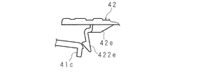
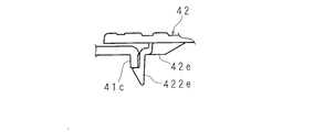
- FIG. 19A, 19B, and 19C are explanatory views showing a state in which the locking claw 42e of the cover 42 locks the back cabinet body 41.
- FIG. 19A When the cover 42 is attached to the back cabinet body 41, the front side surface of the cover 42 (the outer side claw is locked to the peripheral wall end surface of the inner cylinder 41 c provided at the periphery of the opening 41 a of the back cabinet body 41 ( Press the rear side) of the television receiver 1.
- the tip end portion 422e presses the peripheral portion of the opening 41a including the inner cylinder 41c (FIG. 19A).
- the peripheral portion of the pressed opening 41a bends to the front side and the outside of the television receiver 1, and the locking claw 42e is also elastically deformed to the inside (FIG. 19B).
- the claw of the front end portion 422e locks the peripheral wall end surface of the inner cylinder 41c, and the cover 42 is fixed to the back cabinet body 41. (FIG. 19C).
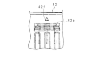
- FIG. 20A is an explanatory diagram of a part of the front side surface of the cover 42 corresponding to the locking claw 42e.
- FIG. 20B is an explanatory diagram in which a locking claw 42e is added to FIG. 20A by a chain line.
- a ⁇ mark 42f is formed slightly outside the position corresponding to the locking claw 42e.
- the locking claw 42e is not visible from the front side of the cover 42.
- the operator can lock the locking claw 42e to the back cabinet body 41 by pressing the front side surface portion of the cover 42 corresponding to the locking claw 42e with the position of the ⁇ mark 42f as a guide.
- FIG. 21 is a partially enlarged view of the peripheral portion of the opening 41a with which the locking claw 42e abuts.
- FIG. 21 shows the periphery of the opening 41a from the rear left diagonally lower side of the television receiver 1.
- a total of two cutouts 41h are provided on the periphery of the opening 41a with which the locking claw 42e abuts, one on each side of the portion where the locking claw 42e abuts.
- the inner peripheral portion of the opening 41a needs to be elastically deformed. When the degree of elastic deformation in the peripheral portion of the opening 41a is small, it is difficult to fix the cover 42 to the back cabinet body 41.
- the latching claw 42e may also bear the elastic deformation in the peripheral portion of the opening 41a, and the latching claw 42e may be damaged.
- the notch 41h has a function of making the peripheral portion of the opening 41a easy to bend. Thereby, the cover 42 can be attached to the back cabinet body 41 without applying an excessive load to the locking claw 42e.
- FIG. 22 is an explanatory view showing a state during the assembly of the back cabinet 4.
- the back cabinet body 41 is placed on a horizontal surface so that the front side is up.
- the cover 42 is held with both hands so that the plate-like protrusions 42c and 42d are first, the cover 42 is face up, and the cover 42 is substantially horizontal.
- the cover 42 is moved to a position where the plate-like protrusions 42c and 42d face the guide protrusion 41f and the protrusion 41b of the back cabinet body 41, respectively.
- the long side of the cover 42 and the long side of the opening 41a are substantially parallel, and the short side of the cover 42 and the short side of the opening 41a are also substantially parallel.
- the other long side of the cover 42 (the long side on the front side of the cover 42) is lifted, and the cover 42 is moved to the surface of the back cabinet body 41.
- the inclination angle at this time is preferably close to the inclination angle of the bottom surface of the recess 411f provided in the guide protrusion 41f and the protrusion 41b of the back cabinet body 41.
- the plate-like protrusions 42c and 42d are inserted into the opening 41e provided in the outer cylinder 41d, that is, the opening 41e behind the recess 411f.
- the central plate-like protrusion 42c since the central plate-like protrusion 42c is longer than the plate-like protrusions 42d on both sides, the central plate-like protrusion 42c first enters the recess 411f of the guide protrusion 41f, and then the plate-like protrusions on both sides. The part 42d enters the recess 411f of the protrusion 41b.
- the central plate-like protrusion 42c is first inserted into the opening 41e, and then the plate-like protrusions 42d on both sides are inserted into the opening 41e. Therefore, the operator can avoid the difficult work of simultaneously inserting the three plate-like protrusions 42c and 42d into the opening 41e.
- a positioning rib 41g for positioning in the left-right direction is provided at the back of the opening 41e into which the central plate-like protrusion 42c is inserted, the plate-like protrusion 42c is guided by the two positioning ribs 41g. The Thereby, the positioning of the cover 42 in the long side direction (left-right direction) and the short side direction of the opening 41e is almost completed.
- the other long side of the cover 42 is slowly rotated downward to gradually reduce the inclination angle of the cover 42.
- the locking claw 42e of the cover 42 contacts the peripheral part of the opening 41a.
- the front side surface of the cover 42 is pressed using the mark 42f provided on the front side surface of the cover 42 as a guide.
- the pressing location is moved along the periphery of the cover 42, the claws of all the locking claws 42 e are locked to the peripheral wall end surface of the inner cylinder 41 c, and the cover 42 is fixed to the back cabinet body 41.
- the back cabinet 4 is provided with a structure for accurately positioning the cover 42 with respect to the back cabinet body 41.
- FIG. 23 and 24 are explanatory views showing a state during the assembly of the back cabinet 4.
- FIG. 23 and FIG. 24 are explanatory diagrams showing how the cover 42 is attached to the back cabinet body 41.
- FIG. 23 shows the upper right portion of the back cabinet 4 in an enlarged manner.
- FIG. 24 is an enlarged view of the upper left portion of the back cabinet 4.
- one rectangular protrusion 41i is provided to protrude.
- the peripheral surface of the opening 41a is equal to the internal peripheral surface of the inner cylinder 41c.
- two guide ribs 42g are provided at the center of the left and right short side edges of the back side surface of the cover 42 facing the protrusion 41i.
- the two guide ribs 42g are provided so as to be separated from each other so that the protrusion 41i can be loosely fitted.
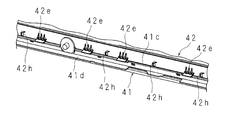
- FIG. 25 is an explanatory diagram showing the peripheral edge of the opening 41 a and the peripheral edge of the cover 42 in the back cabinet body 41 as viewed from the front side of the television receiver 1.
- FIG. 25 is an enlarged view of the vicinity of the lower portion of the opening 41a in the back cabinet body 41 to which the cover 42 is attached.
- Positioning ribs 42 h are provided on the peripheral edge of the back side surface of the cover 42.
- ten positioning ribs 42 h are provided at substantially equal intervals at a location corresponding to the lower long side of the cover 42.
- the positioning rib 42h is provided in the vicinity of the inner peripheral surface of the inner cylinder 41c of the back cabinet body 41.
- 11 positioning ribs 42h are provided at locations corresponding to the upper long side of the cover 42, for example.
- the positioning rib 42h guides the inner cylinder 41c of the back cabinet body 41. Therefore, the cover 42 is positioned in the short side direction. Is done.
- FIG. 25 also shows the locking claw 42e.
- the locking claw 42e is locked to the peripheral wall end of the inner cylinder 41c provided on the back side surface of the back cabinet body 41 at the peripheral edge of the opening 41a.
- the locking claw 42 e has a function of fixing the cover 42 to the back cabinet body 41.
- FIG. 26 is a schematic cross-sectional view of the back cabinet body 41 and the cover 42 in an assembled state.
- FIG. 26 is a cross-sectional view in which the vicinity of the lower long side of the opening 41 a is cut by a cut surface substantially parallel to the normal of the cover 42 and the short side of the cover 42.
- the positioning rib 42h abuts against the base portion of the inner cylinder 41c, thereby restricting the cover 42 from moving downward.
- the positioning ribs 42h may be provided at locations corresponding to the left and right short sides of the cover 42. In such a case, the cover 42 is positioned with respect to the long side direction (left-right direction).
- FIG. 27 is an explanatory view showing a lower peripheral portion of the opening 41a.
- FIG. 27 is a perspective view of the back cabinet main body 41 and the cover 42 in an assembled state, as viewed from the front left oblique upper side near the center of the lower long side of the opening 41a, and is partially enlarged.
- a rectangular projection 41j is projected from the peripheral surface of the inner cylinder 41c.
- two guide ribs 42i are provided in the vicinity of the center of the lower long side of the back side surface of the cover 42 that faces the protrusion 41j.
- the two guide ribs 42i are provided so as to be separated from each other so that the protrusion 41j can be loosely fitted.
- the cover 42 other than the guide rib 42i is omitted.
- the back cabinet main body 41 other than the peripheral portion of the opening 41a is omitted.
- the guide rib 42i provided near the center of the lower long side of the cover 42 guides the protrusion 41j.
- the cover 42 is displaced with respect to the back cabinet main body 41 due to rotation about the normal direction of the cover 42 as a rotation axis.
- the cover 42 is restricted from rotating in the rotational direction with the normal direction of the cover 42 as the rotational axis by the plate-like protrusions 42 c and 42 d inserted into the opening 42 e of the back cabinet body 41.
- the rotation of the cover 42 is restricted by the protrusion 41j and the guide rib 42i in the rotation direction with the normal direction of the cover 42 as the rotation axis. Therefore, the protrusion 41j and the guide rib 42i contribute to the positioning of the cover 42 in the rotation direction with the normal direction of the cover 42 as the rotation axis.
- the television receiver 1 safety can be ensured while dividing the housing.
- a cabinet used for a large thin display device is molded from synthetic resin, the required clamping force increases as the projected area increases, and thus a larger molding machine is required.
- a larger molding machine may not be prepared.
- the cost increases due to the cost of using a larger molding machine.
- the cabinet can be molded by a conventional molding machine.
- electrical products are required to have safety related to combustibility. Therefore, for example, a flame retardant material of V-1 grade is used as the material of the cabinet. However, the price of the flame retardant material is higher as the flame retardant grade is higher.
- a low-flame retardant material is used for the members separated by the members forming the enclosure.
- the cabinet is divided into a cabinet portion that covers a circuit board portion to which a high voltage is applied and a cabinet portion that does not.
- a material having low flame retardancy can be used for the separate piece separated by the former being an enclosure.
- the enclosure has functions such as prevention of mechanical hazards, prevention of electric shock, prevention of electromagnetic interference, dust prevention, waterproofing, airtightness, heat insulation, explosion prevention, and the like. Therefore, materials having different properties with respect to the functions of these enclosures may be used for each divided cabinet portion.
- the back cabinet 4 is divided into two pieces: a cabinet body 41 and a cover 42.
- the back cabinet body 41 is provided with an opening 41a in a region not facing the power supply substrate P, the drive substrate D, and the like. Even if the cover 42 covering the opening a is molded using a low flame retardant material, the safety of fire disaster prevention is ensured as long as the back cabinet body 41 is molded with a high flame retardant material.
- the back cabinet main body 41 may have an opening 41a in a region facing the power supply substrate P, the drive substrate D, and the like. In such a case, the cover 42 covering the opening a is made of a highly flame-retardant material or a material having low electrical conductivity.
- the back cabinet body 41 is made of a material with low flame retardancy or a material with low electrical conductivity. This also realizes cost reduction and safety of fire prevention or electric shock prevention.
- the cover 42 is provided with plate-like protrusions 42c and 42d, and the back cabinet body 41 is provided with a guide protrusion 41f, a protrusion 41b and an opening 41e along one long side of the opening 41a.
- the plate-like protrusions 42c and 42d are inserted into the openings 41e along the guide protrusions 41f and 41b, respectively, so that the cover 42 is substantially aligned with the back cabinet body 41. Can be completed.
- Ribs 421c and 421d are provided on the rear side surface of the television receiver 1 of the plate-like protrusions 42c and 42d.
- the ribs 421c and 421d are provided substantially parallel to the long side direction of the rectangular opening 41e provided in the outer cylinder 41d or the long side direction of the opening 41a.
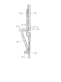
- 28A and 28B are cross-sectional views of the plate-like protrusion 42c and the guide protrusion 41f in a state where the back cabinet 4 is assembled.
- 28A and 28B are cross-sectional views of the plate-like protrusion 42c and the guide protrusion 41f taken along a cutting plane substantially parallel to the normal of the cover 42 and the short side of the cover 42.
- FIG. 28A shows a plate-like protrusion 42c and a guide protrusion 41f in a normal state.
- FIG. 28B shows the plate-like protrusion 42c and the guide protrusion 41f in a state in which the plate-like protrusion 42c is deformed in order to push a foreign object into the television receiver 1 from the opening 41e. Even if a foreign object such as a clip is inserted through the opening 41e, the rib 421c can prevent the foreign object from being inserted. Even if the plate-like protrusion 42c is pushed to the front side of the television receiver 1, the rib 421c follows the plate-like protrusion 42c.
- the rib 421c blocks a foreign material.
- the rib 421d also has a function of preventing foreign matter insertion.
- the outer cylinder 41d is a part of the enclosure of the back cabinet body 41, but only the opening 41e can be said to be a passage connecting the inside and the outside of the television receiver 1. Therefore, the ribs 421c and 421d also have a function as an enclosure.
- the back cabinet 4 may be provided with a structure that does not easily deform even if the plate-like protrusions 42c and 42d are pressed. For example, when the plate-like protrusions 42c and 42d are inserted from the opening 41e, the claw that locks the tips of the plate-like protrusions 42c and 42d is the rear side surface of the back cabinet body 41 (front side surface of the television receiver 1). May be provided.
- the cover 42 is easily fixed to the back cabinet main body 41 when the locking claw 42e is locked to the peripheral wall end of the inner cylinder 41c constituting the peripheral surface of the opening 41a.
- the screw hole 42a of the cover 42 and the boss of the back cabinet body 41 may be omitted.
- the cover 42 may be fixed to the back cabinet body 41 only with screws. In such a case, the locking claw 42e may not be provided.
- the locking claw 42e is a protruding portion protruding from the cover 42, and there is a risk of breakage due to an excessive load.
- the latching claw 42e needs moderate elastic deformation. Therefore, it is necessary to adjust the strength of the locking claw 42e, but by changing the number or thickness of the reinforcing ribs 423e, the shape or size of the rectangular slit 424e, or the thickness of the bent plate portion 421e, The strength of the claw 42e can be adjusted.
- the strength of the locking claw 42e can be adjusted by changing the attribute of the reinforcing rib 423e or the rectangular slit 424e.
- the opening 41 a is provided at the upper center of the back cabinet body 41.
- the opening 41a may be provided in another region of the back cabinet body 41 in consideration of the position of the heat generating substrate.
- the opening 41 a may be cut out including the end of the back cabinet body 41 instead of the inside of the back cabinet body 41. In such a case, the cut-out portion is no longer an opening but a notch.
- the shape of the cover 42 is determined according to the shape of the notch.
- the shape of the opening 41a and the cover 42 is not limited to a substantially rectangular shape.
- various shapes such as an elliptical shape, a circular shape, a trapezoidal shape, an L shape, a T shape, an I shape, and an irregular shape are selected as the shapes of the opening 41a and the cover 42. Good.
- Embodiment 2 The second embodiment relates to a form that eliminates deformation of the back cabinet 4 such as warping, bending, and undulation.
- the deformation of the back cabinet 4 can be a cause of chatter. Therefore, Embodiment 2 is also a form which suppresses generation
- FIG. 29 is an enlarged perspective view of the peripheral edge of the back side surface of the cover 42.
- a locking claw 42e and a hemispherical protrusion 42j are provided on the peripheral edge of the back side surface of the cover 42.
- the hemispherical protrusion 42j has a hemispherical shape and is provided on the outer side of the cover 42 rather than the locking claw 42e.
- the locking claws 42e and the hemispherical protrusions 42j are drawn one by one, but actually, the plurality of locking claws 42e and the hemispherical protrusions 42j alternately surround the periphery of the back surface of the cover 42 at approximately equal intervals. It is provided as follows.
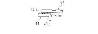
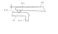
- FIG. 30A and 30B are cross-sectional views of the back cabinet body 41 and the cover 42 near the periphery of the opening 41a.
- FIG. 30A and 30B are cross-sectional views of the assembled back cabinet body 41 and cover 42 taken along a plane substantially parallel to the normal of the cover 42 and the short side of the cover 42, for example.
- FIG. 30A shows a state in which the locking claw 42e locks the peripheral wall of the opening 41a, that is, the peripheral wall end surface of the inner cylinder 41c.
- the back side surface of the cover 42 around the base portion of the locking claw 42e is slightly spaced from the back cabinet body 41.
- FIG. 30B shows a state in which the hemispherical protrusion 42j provided at the edge of the back side surface of the cover 42 is in contact with the front side surface of the peripheral portion of the opening 41a between the inner cylinder 42c and the outer cylinder 42d.
- the front side surface of the back cabinet body 42 corresponding to the space between the inner cylinder 42c and the outer cylinder 42d corresponds to the shelf 41m at the peripheral edge of the opening 41a (see FIG. 6).
- the radius of the hemispherical protrusion 42j is substantially equal to the distance of the gap between the back side surface of the cover 42 around the base portion of the locking claw 42e and the front side surface of the back cabinet body 41.
- the locking claw 42 e regulates deformation in the direction in which the cover 42 floats with respect to the back cabinet body 41.
- the hemispherical protrusion 42j restricts deformation in the direction in which the cover 42 sinks with respect to the back cabinet body 41. Since the cover 42 has a long and slender plate shape, it is easy to be deformed such as warping, bending, and waving. Further, when the thickness of the cover 42 is reduced, the deformation is likely to be remarkable. In particular, in the portion where the back cabinet body 41 and the cover 42 are close to each other, the deformation of the cover 42 is easily noticeable. However, the engaging claws 42e and the hemispherical protrusions 42j arranged alternately have an effect of forcibly making, for example, the undulation of the cover 42 into a small undulation.
- FIG. 31A is a partially enlarged view of the vicinity of the corner portion of the cover 42 in an assembled state.
- FIG. 31B is a cross-sectional view of the back cabinet body 41 and the cover 42 taken along the cutting line II in FIG. 31A.
- 31A and 31B show a deformation in which a corner portion of the cover 42 is lifted.
- the corner portion of the cover 42 is a portion where it is difficult to make a structure that suppresses the deformation that rises. Therefore, as shown in FIG. 31B, the thickness of the corners of the cover 42 is slightly reduced from the inside to the outside of the cover 42.
- angular part of the cover 42 comprises the gentle inclined surface which inclined from the front side to the back side from the inner side to the outer side.
- Embodiment 2 is as described above, and the others are the same as in Embodiment 1. Therefore, the same reference numerals are assigned to the corresponding portions, and the detailed description, operation, and effect thereof are omitted.
- Embodiment 3 relates to a mode in which a change in the width of the groove 43 between the back cabinet body 41 and the cover 42 due to thermal expansion or contraction is suppressed.
- the thermal expansion coefficients of the back cabinet body 41 and the cover 42 may be different.
- the shape of the back cabinet main body 41 and the cover 42 is not a thermally isotropic sphere or a spherical shell, there is anisotropy with respect to thermal deformation. Therefore, the relative positional relationship between the back cabinet main body 41 and the cover 42 after assembly may change with a temperature change.
- FIG. 32 is an enlarged plan view of an example of the assembled back cabinet body 41 and cover 42 from the rear side of the television receiver 1.
- a groove 43 having a slight width is formed between the outer edge of the shelf 41 m (corresponding to the position of the outer cylinder 41 d) and the periphery of the cover 42 at the peripheral edge of the opening 41 a of the back cabinet body 41.
- the groove 43 surrounds the entire circumference of the cover 42.
- the width of the groove 43 is constant throughout the circumference of the cover 42.
- the bottom surface of the groove 43 corresponds to the shelf 41m at the periphery of the opening 41a.
- the groove 43 gives an appearance to the back cabinet 4 and serves as a buffer for preventing contact between the peripheral surface of the opening 41a of the back cabinet body 41 (inner peripheral surface of the inner cylinder 41c) and the peripheral end surface of the cover 42 due to thermal deformation. Has the function of forming. However, when the relative positional relationship between the back cabinet main body 41 and the cover 42 changes due to thermal deformation, the width of the groove 43 may vary depending on the circumferential position of the cover 42. In such a case, the aesthetic appearance of the television receiver 1 is impaired.
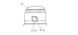
- FIG. 33A is a perspective view showing a hole 41k provided at the upper edge of the opening 41a of the back cabinet body 41 from the lower left diagonal of the television receiver 1.
- FIG. 33A shows an example of a hole 41 k provided in the back cabinet body 41.
- FIG. 33B is a perspective view showing the cylindrical protrusion 42k provided on the peripheral edge of the back side surface of the upper portion of the cover 42 from the front right upper side of the television receiver 1.
- FIG. 33B shows an example of a cylindrical protrusion 42 k provided on the cover 42.
- the hole 41k has a rectangular shape, for example, and is opened in the shelf 41m at the periphery of the opening 41a.
- the hole 41k may have a circular shape, an elliptical shape, or the like.
- the hole 41k is disposed between the inner cylinder 41c and the outer cylinder 41d.
- a plurality of holes 41k are formed along the circumference of the opening 41a.
- the number of holes 41k arranged on the upper side and the lower side of the opening 41a is, for example, twelve.
- the number of holes 41k arranged on both sides of the opening 41a is, for example, five each.
- the cylindrical protrusion 42k has a cylindrical shape and is erected on the back side of the cover 42.
- the tip of the cylindrical protrusion 42k is rounded and hemispherical.
- the cross-sectional area when the cylindrical protrusion 42k is cut along a cutting plane perpendicular to the height direction is smaller than the opening area of the hole 41k.
- the same number of cylindrical protrusions 42k as the holes 41k are formed along the periphery of the cover 42 at the peripheral edge of the back side surface of the cover 42.
- the cylindrical protrusion 42k is provided so as to be disposed at a position facing the hole 41k.
- the cylindrical protrusion 42k is configured to be loosely fitted in the hole 41k at the opposing position.
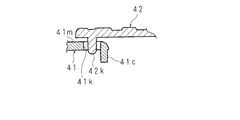
- FIG. 34A is a cross-sectional view of an example of the hole 41k and the cylindrical protrusion 42k.
- FIG. 34A shows a state in which the back cabinet body 41 and the cover 42 in an assembled state are cut by a cut surface substantially parallel to the normal line of the cover 42 and, for example, the short side of the cover 42.
- FIG. 34A shows an enlarged cross section of a part of the holes 41k and the cylindrical protrusions 42k.
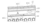
- FIG. 34B is a perspective view of the back cabinet body 41 and the cover 42 in an assembled state as viewed from the front side of the cover 42. In FIG. 34B, the hole 41k, the cylindrical protrusion 42k, and the locking claw 42e which are hidden by the cover 42 and are not originally visible are indicated by chain lines.
- FIG. 34B shows a cross-sectional view of an example of the hole 41k and the cylindrical protrusion 42k.
- 34B shows a state in which the cylindrical protrusion 42k is loosely fitted in the approximate center of the hole 41k.
- 34A and 34B show an example of the hole 41k and the cylindrical protrusion 42k when the cover 42 is attached to the back cabinet body 41, respectively.
- the restriction orientation and the restriction amount of the movement of the cylindrical protrusions 42k with respect to the hole 41k vary depending on the position of the circumference of the cover 42 and are various.
- the width of the groove 43 between the back cabinet body 41 and the cover 42 is suppressed from changing for each circumferential position of the cover 42, the width of the groove 43 is constant at any part of the circumference of the cover 42. Kept. Therefore, the hole 41k and the cylindrical protrusion 42k contribute to maintaining the aesthetic appearance of the back cabinet 4.
- Embodiment 3 is as described above, and the others are the same as Embodiments 1 and 2. Therefore, the same reference numerals are assigned to the corresponding parts, and the detailed description, operation, and effect thereof are omitted.
- Embodiment 4 relates to a form in which a plurality of openings are formed by a lattice-like braid instead of hollowing out the interior of the back cabinet 4 by a single opening 41a.
- the fourth embodiment relates to a mode in which a thin punching sheet having a large number of holes is pasted on a braid forming a plurality of openings instead of the cover 42 covering the openings.
- FIG. 35A is a plan view of the back cabinet body 410 viewed from the rear side of the television receiver 1.
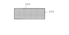
- FIG. 35B is a plan view of the cover sheet 420 as viewed from the rear side of the television receiver 1.
- FIG. 35A and FIG. 35B each show an example of a dividing member of the back cabinet 4 as viewed from the rear side of the television receiver 1.
- the back cabinet 4 includes a back cabinet body 410 and a cover sheet 420.
- the back cabinet main body 410 has the same inner cylinder 41c and outer cylinder 41d as the back cabinet main body 41 (in FIG. 35A, the inner cylinder 41c and the outer cylinder 41d are not shown. About the inner cylinder 41c and the outer cylinder 41d) For example, see FIG. 4 and FIG. However, the back cabinet body 410 does not have the protrusion 41b, the guide protrusion 41f, and the like. The inner cylinder 41c and the outer cylinder 41d have an enclosure function.
- the back cabinet body 410 has a plurality of sets 41m arranged in the vertical direction and the horizontal direction at a portion corresponding to the opening 41a of the back cabinet body 41.
- a plurality of openings 410a are formed in the upper center of the back cabinet body 410 by the braid 41m having the lattice shape.
- the thickness and number of the braid 41m may be determined in consideration of the strength of the back cabinet body 410.
- FIG. 35A shows an example of the thickness and the number of the sets 41m.
- the back cabinet body 410 including the inner cylinder 41c, the outer cylinder 41d, and the assembly 41m is formed by integral molding using a material (for example, a resin material) of flame retardancy V-1 or higher.
- the cover sheet 420 is a lightweight and thin sheet formed using a flame retardant HB material (for example, a resin material).
- the shape and planar size of the cover sheet 420 are determined according to the entirety of the plurality of openings 410a.
- the shape of the cover sheet 420 is a rectangular shape.
- the thickness of the cover sheet 420 is, for example, 0.5 mm.
- the cover sheet 420 is provided with many holes 42m by punching.
- the size of the hole 42 may be a size that satisfies the safety standards related to foreign matter shielding.
- the shape of the hole 42m is not particularly limited. For example, when the hole is circular, the diameter thereof is, for example, 2 mm to 4 mm.
- the cover sheet 420 does not have the locking claw 42e, the plate-like protrusions 42c, 42d, etc., which the cover 42 has.
- FIG. 36 is a plan view of an example of the back cabinet 4 as viewed from the rear side of the television receiver 1.
- the cover sheet 420 is attached to the assembly m of the back cabinet body 410 with an adhesive, a double-sided tape, or the like.
- the cover sheet 420 is lightweight, and the cover sheet 420 can be easily attached in the assembly work of the television receiver 1. As a result, the burden on the worker is reduced and the assembly efficiency is improved. Since the inner cylinder 41c and the outer cylinder 41d having the function of an enclosure are provided around the lattice portion of the back cabinet body 410 including the assembly 41m, the cover sheet 420 has Flame retardant grade can be lowered. The outer cylinder 41d may not be provided.
- the opening 410a formed in the back cabinet body 410 and the hole 42m formed in the cover sheet 420 have an effect of releasing heat inside the television receiver 1 to the outside.
- Embodiment 4 is as described above, and the others are the same as those in Embodiments 1 to 3. Therefore, the same reference numerals are assigned to the corresponding parts, and detailed descriptions, operations, and effects are omitted.
- Embodiment 5 relates to a form in which the back cabinet 4 is linearly divided into two upper and lower housing parts.
- the lower rear side surface of the display unit 2 provided with heating elements such as the power supply substrate P and the drive substrate D is covered with a highly flame-retardant lower back cabinet.
- the rear upper portion of the display unit 2 where no heating element is provided is covered with a low flame retardant upper back cabinet.
- the back cabinet 4 includes an upper back cabinet 45 and a lower back cabinet 46.
- FIG. 37A is a plan view of the upper back cabinet 45 as viewed from the rear side of the television receiver 1.
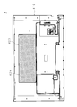
- FIG. 37B is a plan view of the lower back cabinet 46 as viewed from the rear side of the television receiver 1.
- FIG. 37A and FIG. 37B each show an example of a dividing member of the back cabinet 4 as viewed from the rear side of the television receiver 1.
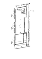
- FIG. 38A is a plan view of the upper back cabinet 45 as viewed from the front side of the television receiver 1.
- FIG. 38B is a plan view of the lower back cabinet 46 as viewed from the front side of the television receiver 1.
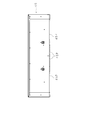
- FIG. 39A is a perspective view of the upper back cabinet 45 as viewed obliquely from the lower left rear side of the television receiver 1.
- FIG. 39B is a perspective view of the lower back cabinet 46 as viewed obliquely from the lower left rear side of the television receiver 1.
- FIG. 39A and FIG. 39B show an example of a dividing member of the back cabinet 4 as viewed from diagonally below the rear left side of the television receiver 1.
- the back cabinet 4 according to the fifth embodiment is largely divided into an upper upper back cabinet 45 and a lower lower back cabinet 46 by a straight horizontal dividing line passing through the center.
- the shapes of the upper back cabinet 45 and the lower back cabinet 46 viewed in plan from the front side (rear side) and the rear side (front side) are both horizontally long and substantially rectangular.
- the upper back cabinet 45 is a housing portion that covers the upper rear side surface of the display unit 2 where no heating element is installed, and is formed by integral molding using a flame-retardant HB material (for example, a resin material).
- the lower back cabinet 46 is a casing portion that covers the power supply substrate P, the drive substrate D, and the like that generate heat when voltage is applied from the rear side, and is made of a material (for example, resin material) having flame retardancy V-1 or higher. And formed by integral molding.
- a rib 46L extending in the left-right direction and having the function of an enclosure projects from a portion near the upper end of the back side (front side) of the lower back cabinet 46 (see FIG. 38B). The rib 46L will be described later.
- a pocket 45P is formed at the lower end of the upper back cabinet 45.
- the mouth of the pocket 45P is provided downward, and the depth direction of the pocket 45P is upward.
- the pocket 45P has a shape extending in the left-right direction, and the width in the left-right direction of the pocket 45P is longer than the length in the depth direction.
- four pockets 45P are provided in the upper back cabinet 45.
- Each of the pockets 45P is spaced apart in the left-right direction along the lower end of the upper back cabinet 45, and arranged in the left-right direction. The lengths in the depth direction of the four pockets 45P are the same.
- the width in the left-right direction of the pockets 45P arranged one by one at the left and right ends is equal. Further, when viewed from the front, the widths in the left-right direction of the two pockets 45P sandwiched between the left and right pockets 45P and disposed on both sides of the lower center of the upper back cabinet 45 are equal. The width in the left-right direction of the pocket 45P disposed at the left and right ends is wider than the width in the left-right direction of the pocket 45P disposed on both sides of the center.
- the arrangement and size of the pockets 45P are symmetrical with respect to the center of the lower end of the upper back cabinet 45.
- a hook 46 ⁇ / b> H extending upward is formed at the upper end of the lower back cabinet 46.
- 14 hooks 46H are provided at the upper end of the lower back cabinet 46.
- the 14 hooks 46H have the same vertical length.
- Four hooks 46H are provided at positions of the lower back cabinet 46 facing the pockets 45P arranged one by one at the left and right ends of the lower end of the upper back cabinet 45, respectively.
- Three hooks 46H are provided at positions of the lower back cabinet 46 facing the two pockets 45P arranged on both sides of the lower end center of the upper back cabinet 45, respectively.
- the width in the left-right direction of the hook 46H varies depending on the hook 46H.
- Each of the four hooks 46H provided at the position of the lower back cabinet 46 facing the pockets 45P arranged one by one at the left and right ends of the lower end of the upper back cabinet 45 has the longest horizontal width.
- Each of the three hooks 46H provided at the position of the lower back cabinet 46 opposed to the two pockets 45P disposed on both sides of the lower center of the upper back cabinet 45 has a different width in the left-right direction. .
- the width in the left-right direction of each of these three hooks 46H is the longest hook 46H located in the center among the three, and the hook 46H closer to the center of the upper end of the lower back cabinet 46 is the shortest.
- the arrangement and size of the 14 hooks 46H are symmetrical with respect to the center of the upper end of the lower back cabinet 46.
- the hook 46H is configured to be insertable into the pocket 45P, and the upper back cabinet 45 and the lower back cabinet 46 are configured to be coupled by the hook 46H being locked inside the pocket 45P.
- FIG. 40 is an explanatory diagram showing a state during the assembly of the back cabinet 4.
- FIG. 40 shows portions of the upper back cabinet 45 and the lower back cabinet 46. Further, the white arrow in FIG. 40 indicates the insertion direction of the hook 46H into the pocket 45P.
- a plurality of hooks 46H are inserted into one pocket 45P, and pocket partition ribs 45PL for partitioning the inside of the pocket 45P are provided on the inner surface of the corresponding pocket 45P between the hooks 46H that are separated from each other.
- the pocket partition rib 45PL is provided on the inner surface of the pocket 45P facing the front side of the television receiver 1.
- FIG. 41A, 41B, and 41C are explanatory views showing a state during the assembly of the back cabinet 4.
- FIG. 41A, 41B, and 41C show portions of the upper back cabinet 45 and the lower back cabinet 46, respectively.
- the lower side and the upper side in FIGS. 41A, 41B, and 41C are the front side and the back side of the back cabinet 4, respectively.
- 41A, 41B, and 41C are the front side and the rear side of the television receiver 1, respectively.
- the left direction and the right direction in FIGS. 41A, 41B, and 41C are above and below the television receiver 1, respectively.
- 41A, 41B, and 41C show cross sections when the upper back cabinet 45 and the lower back cabinet 46 are cut along a plane perpendicular to the left-right direction of the television receiver 1, respectively.
- FIG. 41A, 41B, and 41C show cross sections when the upper back cabinet 45 and the lower back cabinet 46 are cut along a plane perpendicular to the left-right direction of the television receiver 1, respectively.
- FIG. 41A shows a state before the hooks 46H of the lower back cabinet 46 are inserted into the pockets 45P of the upper back cabinet 45.
- FIG. 41B shows a state in the middle of inserting the hook 46H of the lower back cabinet 46 into the pocket 45P of the upper back cabinet 45.
- 41C shows a state in which the hooks 46H of the lower back cabinet 46 are locked inside the pockets 45P of the upper back cabinet 45.
- a stepped portion 461 that is bent and falls to the back side (front side) is provided.
- the hook 46H is provided at the tip of the step portion 461.
- the hook 46H is bent from the tip of the step portion 461 and further falls to the back side (front side). Therefore, the step portion 461 and the hook 46H have a crank shape having a two-step bent portion.
- a hook 46h that bends to the front side (rear side) of the back cabinet 4 is provided at the tip of the hook 46H.
- a hook locking rib 45L that can be locked to the hook 46h of the hook 46H is provided.
- the hook locking rib 45L has a height that increases from the mouth of the pocket 45P toward the back, and is interrupted in front of the innermost surface of the pocket 45P.
- the hook locking rib 45L has a triangular prism shape, and the hook locking rib 45L in FIGS. 41A, 41B, and 41C has a wedge shape.
- two hook locking ribs 45L are provided on the inner surface of the pocket 45P for one hook 46H (see FIG. 40).
- the hook locking ribs 45L are arranged in the left-right direction of the television receiver 1 so as to correspond to all the 14 hooks 46H.
- the hook 46H When the hook 46h of the hook 46H is locked to the hook locking rib 45L, the hook 46H is inclined so that the lower end side of the lower back cabinet 46 is located on the front side (rear side) with respect to the upper back cabinet 45 (FIG. 41B).
- the hook 46H is inserted into the pocket 45P so as to cover the hook locking rib 45L with the hook 46H.
- the lower back cabinet 46 is rotated about the flange 46h so that the lower end side of the lower back cabinet 46 is brought closer to the back side (front side) so that the lower back cabinet 46 is not inclined with respect to the upper back cabinet 45.
- the lower side surface of the flange 46h is in contact with the upper side surface of the hook locking rib 45L, and the back side (front side) surface of the hook 46H is in the pocket 45P. Abuts against the inner surface of the front side (rear side). Furthermore, when the hook 46 ⁇ / b> H is locked to the hook locking rib 45 ⁇ / b> L (FIG. 41C), the lower end surface of the upper back cabinet 45 comes into contact with the tip surface of the stepped portion 461. When the lower back cabinet 46 is separated from the upper back cabinet 45, the lower back cabinet 46 is removed by a procedure reverse to the order shown in FIGS. 41A, 41B, and 41C.
- the front side surface (rear side surface) of the stepped portion 461 and the front side surface (rear side surface) of the upper back cabinet 45 are arranged on the hook 46H so as to be a smooth plane.
- the step of the bent portion at the base is adjusted. Thereby, the beauty
- a pocket reinforcing rib 45PLr that reinforces the strength of the pocket 45P is provided at a corner formed by the innermost surface on the back side (front side) in the pocket 45P.
- the rib 46L protrudes from the back side surface (front side surface) in the base part of the step part 461.
- the rib 46L functions as an enclosure that separates the upper back cabinet 45 from the power supply substrate P, the drive substrate D, and the like that the lower back cabinet 46 covers.
- FIG. 42 is a plan view of an example of the back cabinet 4 as viewed from the rear side of the television receiver 1.
- FIG. 43 is a plan view of an example of the back cabinet 4 as viewed from the front side of the television receiver 1.
- FIG. 44 is a perspective view of an example of the back cabinet 4 as viewed from diagonally below the rear left side of the television receiver 1.
- the hook 46 ⁇ / b> H is housed in the pocket 45 ⁇ / b> P, and the hook 46 ⁇ / b> H cannot be seen from the outside and inside of the television receiver 1 (FIGS. 42, 43, and 44).
- the pocket 45P cannot be seen on the appearance (FIGS. 42 and 44).
- the rib 46L cannot be seen (FIGS. 42 and 44).
- the back cabinet 4 is viewed from the inside of the television receiver 1 (FIG. 43)
- the rib 46L is a wall that partitions the upper back cabinet 45 and the lower back cabinet 46 in a straight line.
- the front cabinet 3, the display unit 2, and the upper back cabinet 45 are aligned and overlapped in this order on the horizontal plane. And a screw is inserted from the screw hole provided in the periphery of the upper back cabinet 45, and these members are fixed with a screw.
- the hook 46H is inserted into the pocket 45P and the lower back cabinet 46 is temporarily fixed to the upper back cabinet 45 by the procedure shown in FIGS. 41A, 41B, and 41C. Thereafter, a screw is inserted from a screw hole provided at the periphery of the lower back cabinet 46, and the lower back cabinet 46 is fixed to the front cabinet 3 and the display unit 2 with screws.
- the back cabinet 4 is divided into the upper back cabinet 45 and the lower back cabinet 46, the mold pressure during molding can be reduced.
- the upper back cabinet 45 and the lower back cabinet 46 have a coupling structure (a pocket 45P and a hook 46H) that can be easily assembled and disassembled. Therefore, even if the number of parts of the back cabinet 4 is increased to 2, the assembly work and the disassembly work of the back cabinet 4 are not hindered.
- the lower back cabinet 45 having the rib 46L is formed as a single enclosure, even if the flame retardance grade of the upper back cabinet 45 is lowered, there is no problem in safety standards. According to the television receiver 1 according to the fifth embodiment, since only the lower back cabinet 46 can be removed, maintenance work for the receiving unit T, the power supply board P, or the drive board D can be easily performed.
- Embodiment 5 is as described above, and the others are the same as those in Embodiments 1 to 4. Therefore, the same reference numerals are assigned to the corresponding parts, and the detailed description, operation, and effect thereof are omitted.
- Embodiment 6 relates to a form in which the back cabinet 4 including the back cabinet body 41 and the cover 42 according to the first embodiment is integrally formed by two-color molding (double molding). Therefore, the back cabinet 4 is not divided into the back cabinet main body 41 and the cover 42, but is integrated.
- the part corresponding to the back cabinet body 41 is molded from a highly flame retardant resin material (for example, V-1 or higher), and the part corresponding to the cover 42 is molded from a low flame retardant resin material (for example, HB).
- the cabinet 4 according to Embodiment 6 Since the back cabinet 4 according to Embodiment 6 is integral, when assembling the television receiver 1, it is not necessary to combine the parts corresponding to the back cabinet body 41 and the cover 42. Therefore, the cabinet 4 according to the sixth embodiment does not have the protrusion 41b, the guide protrusion 41f, and the like, the locking claw 42e, the plate-like protrusions 42c, 42d, and the like that the back cabinet body 41 and the cover 42 have.
- Example 6-1 relates to an example in which a partition is provided between cavities inside the mold corresponding to the back cabinet body 41 and the cover 42 in order to form the back cabinet 4.
- FIG. 45 is a cross-sectional view showing an example of a mold 5 for molding the back cabinet 4.
- the upper and lower portions in FIG. 45 correspond to the upper and lower portions of the back cabinet 4, respectively.
- 45 correspond to the front side and the back side of the back cabinet 4, respectively.
- FIG. 45 is a cross-sectional view of the mold 5 cut along a plane parallel to the vertical direction and the normal line of the back cabinet 4.
- the mold 5 includes a male mold 51, a female mold 52, and a partition 53.
- the male mold 51 is a movable core.
- the female mold 52 is a fixed cavity.
- the female mold 52 has runners 521, 522, and 523 which are flow paths for resin material filled in the cavities 54 and 55 (cavities) inside the mold 5.
- the runner 521 is a flow path for molding a portion corresponding to the cover 42.
- the runners 522 and 523 are flow paths for molding a portion corresponding to the back cabinet body 41. For example, by sliding the male mold 51, the mold 5 is closed (clamped) and opened.
- FIG. 46 is an explanatory diagram showing the partition portion 53 superimposed on the back cabinet body 41.
- FIG. 46 shows a state in which the back cabinet body 41 and the partition 53 are viewed from the rear side of the television receiver 1.
- the partition portion 53 is a frame-like member that is disposed on the portion of the female mold 52 that corresponds to the periphery of the opening 41 a of the back cabinet body 41.
- the partition portion 53 has a function of clogging the resin material so that the resin material does not move to the cavity 54 corresponding to the outer back cabinet body 41 when the resin material is injected into the cavity 55 corresponding to the cover 42 in the mold 5.
- the width of the frame of the partition 53 as viewed from the front side is equal to the width of the groove 43, for example.
- the groove 43 is a space formed between the outer edge of the shelf 41m at the peripheral edge of the opening 41a and the periphery of the cover 42 (see FIGS. 3, 32, and 34B).
- the partition 53 is attached to the female mold 52, the male mold 51 is slid, and the mold 5 is closed.
- a low flame retardant resin material is injected into the cavity 55 corresponding to the cover 42 by the nozzle through the runner 521.
- the mold 5 is opened.
- the partition part 53 is removed from the female mold 52.
- the mold 5 is closed.
- a highly flame-retardant resin material is injected into the cavity 54 corresponding to the back cabinet body 41 by a nozzle.
- the mold 5 is opened when the highly flame-retardant resin material constituting the back cabinet body 41 is cooled.
- the back cabinet 4 which is a molded product is taken out from the mold 5.
- an inner cylinder 41 c and an outer cylinder 41 d made of a highly flame-retardant resin are formed around a portion corresponding to the cover 42.
- the inner cylinder 41c and the outer cylinder 41d have an enclosure function. 45 may be extended in the direction of the male mold 51 without providing the inner cylinder 41c and the outer cylinder 41d.
- the injected highly flame-retardant resin material fills the cavity 54 occupied by the partition part 53.
- the highly flame-retardant resin material filled in the cavity 54 occupied by the partition portion 53 constitutes a portion having the function of an enclosure. Will do.
- Example 6-1 a portion corresponding to the cover 42 was formed, and then a portion corresponding to the back cabinet body 41 was formed. However, this molding order may be reversed. That is, after the portion corresponding to the back cabinet body 41 is formed, the portion corresponding to the cover 42 may be formed.
- the cycle of forming the back cabinet 4 includes the process of attaching and removing the partition 53, but from the mold closing process to the mold taking process,
- the back cabinet 4 can be formed in a cycle.
- the embodiment 6-2 relates to an embodiment in which a portion corresponding to the cover 42 is formed in advance, and the portion corresponding to the back cabinet body 41 is formed after the formed cover 42 is attached to the female mold 52.
- FIG. 47 is a cross-sectional view showing an example of a mold 50 for molding the back cabinet 4.
- the upper and lower portions in FIG. 47 correspond to the upper and lower portions of the back cabinet 4, respectively.
- 47 correspond to the front side and the back side of the back cabinet 4, respectively.
- FIG. 47 is a cross-sectional view of the mold 50 cut along a plane parallel to the vertical direction and the normal line of the back cabinet 4.
- the mold 50 includes a male mold 510 and a female mold 520.
- the male mold 510 is a movable core.
- Female mold 520 is a fixed cavity.
- the female mold 520 includes runners 524 and 525 that are resin flow paths filled in the cavity 540 portion inside the mold 50.
- the runners 524 and 525 are flow paths for forming a portion corresponding to the back cabinet body 41. For example, by sliding the male mold 510, the mold 50 is closed and opened.
- Cavities 540 and 541 are formed inside the closed mold 50.
- the cavity 540 is a space corresponding to the back cabinet body 41.
- the cavity 541 is a space corresponding to the cover 42.
- a portion of the cavity 540 that is in contact with the cavity 541 is a portion that corresponds to the back cabinet body 41 that is in contact with a portion corresponding to the cover 42, and protrudes toward the front side of the television receiver 1.
- the highly flame-retardant resin material filled in the protruding cavity 540 constitutes a part having the function of an enclosure.
- Example 6-2 a method for forming the back cabinet 4 according to Example 6-2 will be described.
- the part of the back cabinet 4 corresponding to the cover 42 is molded.
- a mold (not shown) for molding the portion of the back cabinet 4 corresponding to the cover 42 is prepared.
- a low flame retardant resin material is injected into the mold, and after cooling the low flame retardant resin material, a molded product that is a part of the back cabinet 4 corresponding to the cover 42 is taken out from the mold.
- the member of the back cabinet 4 corresponding to the cover 42 formed in advance is attached to the portion of the female mold 520 corresponding to the cavity 541.
- the male mold 510 is slid and the mold 50 is closed.
- a highly flame-retardant resin material is injected into the cavity 540 corresponding to the back cabinet body 41 by a nozzle.
- the mold 50 is opened when the highly flame-retardant resin material constituting the portion corresponding to the back cabinet body 41 is cooled.
- the back cabinet 4 which is a molded product is taken out from the mold 50.
- Example 6-3 runners for separately injecting the high flame retardant resin material and the low flame retardant resin material are provided in the mold cavities corresponding to the back cabinet body 41 and the cover 42, respectively.
- the present invention relates to an embodiment in which a high flame retardant resin material and a low flame retardant resin material are simultaneously injected into a mold.
- FIG. 48 is a cross-sectional view showing an example of a mold 500 for molding the back cabinet 4.
- the upper and lower parts in FIG. 48 correspond to the upper and lower parts of the back cabinet 4, respectively.
- 48 correspond to the front side and the back side of the back cabinet 4, respectively.
- FIG. 48 is a cross-sectional view of the mold 500 taken along a plane parallel to the vertical direction and the normal line of the back cabinet 4.
- the mold 500 includes a male mold 550 and a female mold 560.
- the male mold 550 is a movable core.
- Female mold 560 is a fixed cavity.
- Cavities 542 and 543 are formed inside the closed mold 500.
- the cavity 542 is a space corresponding to the back cabinet body 41.
- the cavity 543 is a space corresponding to the cover 42.
- the female mold 560 has runners 526 to 533 which are flow paths for resin material filled in the cavities 542 and 543 inside the mold 500.
- the runners 526, 527, 528, 529, and 530 are flow paths for forming a portion corresponding to the back cabinet body 41.
- the runners 531, 532, and 533 are flow paths for forming a portion corresponding to the cover 42.
- the mold 500 is closed and opened by sliding the male mold 550.
- the boundary between the cavity 542 and the cavity 543 is located between the runner 527 and the runner 531 gate and between the runner 528 and the runner 533 gate. It is preferable that the boundary between the portion corresponding to the back cabinet body 41 and the portion corresponding to the cover 42 in the back cabinet 4 after molding is not greatly shifted by the flow of the resin material. Therefore, the gates of the runners 527 and 531 and the gates of the runners 528 and 533 are arranged so as to be adjacent to the boundary between the cavity 542 and the cavity 543.
- the male mold 550 is slid and the mold 500 is closed.
- a highly flame-retardant resin material is injected into a cavity 542 at a portion corresponding to the back cabinet body 41 by a nozzle.
- the low-flame retardant resin material is injected into the cavity 543 corresponding to the cover 42 by the nozzles through the runners 531 to 532.
- the mold 500 is opened.
- the back cabinet 4 which is a molded product is taken out from the mold 500.
- Example 6-3 the back cabinet 4 is formed by simultaneously forming a portion corresponding to the back cabinet body 41 and a portion corresponding to the cover 42 by two-color molding in one cycle. Therefore, the molding efficiency of the back cabinet 4 in Example 6-3 is high. Unlike the mold 5 in Example 6-1, the mold 500 is not provided with the partition portion 53. Therefore, the injected low flame retardant resin material and high flame retardant resin material are mixed somewhat in the injection process or pressure holding process. Therefore, the boundary between the back cabinet body 41 serving as the enclosure and the cover 42 may be shifted to a safer side so as to satisfy the safety standard.
- the portions corresponding to the back cabinet body 41 and the cover 42 according to the first embodiment are integrally formed by two-color molding.
- the portions corresponding to the upper back cabinet 45 and the lower back cabinet 46 according to Embodiment 5 may be integrally formed by two-color molding.
- a method of providing a partition part in the mold is conceivable.
- a method is conceivable in which a portion corresponding to the upper back cabinet 45 or the lower back cabinet 46 is formed in advance, the formed portion is attached to a mold, and the remaining portion is formed.
- the part constituted by the high flame retardant resin material and the part constituted by the low flame retardant resin material are integrally formed in a short time. can do. Therefore, the manufacturing method of the back cabinet 4 according to Embodiment 6 can reduce the manufacturing cost of the back cabinet 4.
- each part When a part composed of a high flame retardant resin material and a part composed of a low flame retardant resin material are molded separately, each part must have a structure for bonding these parts. .
- the assembling work of the television receiver 1 requires a process of joining these parts.
- a part constituted by a high flame retardant resin material and a part constituted by a low flame retardant resin material The back cabinet 4 is integrated from the beginning. Therefore, the process of combining these sites is not necessary. Therefore, the method for manufacturing the back cabinet 4 according to Embodiment 6 can reduce the cost and time required for assembling the television receiver 1.
- Embodiment 6 is as described above, and the others are the same as those in Embodiments 1 to 5. Therefore, the same reference numerals are assigned to the corresponding parts, and the detailed description, operation, and effect thereof are omitted.
Landscapes
- Physics & Mathematics (AREA)
- Nonlinear Science (AREA)
- Engineering & Computer Science (AREA)
- Signal Processing (AREA)
- Multimedia (AREA)
- Crystallography & Structural Chemistry (AREA)
- Optics & Photonics (AREA)
- General Physics & Mathematics (AREA)
- Chemical & Material Sciences (AREA)
- Mathematical Physics (AREA)
- Devices For Indicating Variable Information By Combining Individual Elements (AREA)
- Casings For Electric Apparatus (AREA)
- Microelectronics & Electronic Packaging (AREA)
Abstract
筐体を分割しつつ、安全性を担保することができる表示装置及びテレビ受信装置を提供する。 前側に表示面を有する表示部と、該表示部の周縁部を取り囲むフロントキャビネットと、前記表示部の後側を覆うバックキャビネットとを備え、前記バックキャビネットは開口部41aが設けられたバックキャビネット本体41及び開口部41aを閉鎖するようにバックキャビネット本体41に取り付けられるカバーからなる表示装置において、カバーはバックキャビネット本体41を構成する材料と異なる材料から構成されている。
Description
本発明は、液晶テレビ、プラズマテレビ等の表示装置及びテレビ受信装置に関する。
薄型テレビ等の薄型表示装置は、表示部を覆うフロントキャビネット及びバックキャビネットからなる筐体を有している。バックキャビネットは、搬送性の向上、組み立ての容易化等のために複数の部材に分割されることがある(例えば、特許文献1、2参照)。
ところで、薄型表示装置は大型化傾向にあるため、その筐体を成形する場合、次々とより大型の成形機が必要となる。新たな大型成形機の投入が薄型表示装置の生産体制に間に合わない場合、筐体を複数の部材に分割し、分割した筐体の各部材を既存の成形機により成形する。
ところで、薄型表示装置は大型化傾向にあるため、その筐体を成形する場合、次々とより大型の成形機が必要となる。新たな大型成形機の投入が薄型表示装置の生産体制に間に合わない場合、筐体を複数の部材に分割し、分割した筐体の各部材を既存の成形機により成形する。
一方、火災、その他の事故から人命及び財産を保護するため、製品機器に関する火災防護並びに機械的及び電気的防護の安全規格が定められている。そこで、表示装置の筐体を複数の部材に分割した場合であっても、火災防護等の安全規格をクリアする必要がある。
本発明は斯かる事情に鑑みてなされたものである。その目的は、筐体を分割しつつ、安全性を担保することができる表示装置及びテレビ受信装置を提供することにある。
本願に係る表示装置は、前側に表示面を有する表示部と、該表示部の周縁部を取り囲むフロントキャビネットと、前記表示部の後側を覆うバックキャビネットとを備え、前記バックキャビネットは開口部が設けられたバックキャビネット本体及び該開口部を閉鎖するように該バックキャビネット本体に取り付けられる蓋体からなる表示装置において、前記蓋体は前記バックキャビネット本体を構成する材料と異なる材料から構成されていることを特徴とする。
本願に係る表示装置では、表示部、フロントキャビネット及びバックキャビネットを備えている。表示部は、前側に表示面を有す。フロントキャビネットは、表示部の周縁部を取り囲んでいる。バックキャビネットは、表示部の後側を覆っている。バックキャビネットは、バックキャビネット本体及び蓋体を含む。バックキャビネット本体には、開口部が設けられている。蓋体は、バックキャビネット本体の開口部を閉鎖するように、バックキャビネット本体に取り付けられる。バックキャビネット本体及び蓋体は、異なる材料から構成されている。
バックキャビネット本体及び蓋体の両者を同一材料で構成した場合、高コストとなる可能性がある。バックキャビネット本体及び蓋体の一方を安全規格の等級が低い材料で成形することにより、コスト削減を図ることができる。一方、バックキャビネット本体及び蓋体の他方を安全規格の等級が高い材料で成形することにより、安全性が担保される。
バックキャビネット本体及び蓋体の両者を同一材料で構成した場合、高コストとなる可能性がある。バックキャビネット本体及び蓋体の一方を安全規格の等級が低い材料で成形することにより、コスト削減を図ることができる。一方、バックキャビネット本体及び蓋体の他方を安全規格の等級が高い材料で成形することにより、安全性が担保される。
本願に係る表示装置は、前記蓋体は前記バックキャビネット本体よりも難燃性の低い材料から構成されていることを特徴とする。
本願に係る表示装置では、蓋体はバックキャビネット本体よりも難燃性の低い材料から構成されている。発火の危険性が小さいバックキャビネットの領域に開口部を設置する場合、蓋体の材料をバックキャビネット本体の材料よりも難燃性の低いものにすることで、コストの削減を図ることができる。一方、バックキャビネット本体を難燃性の高い材料で成形することにより、火災防護の安全性は担保される。
本願に係る表示装置は、前記表示部及びバックキャビネットの間に固定された回路基板を備え、前記開口部は前記バックキャビネット本体における前記回路基板と対向しない領域に設けられていることを特徴とする。
本願に係る表示装置では、回路基板を備えている。回路基板は、表示部とバックキャビネットの間に固定される。バックキャビネット本体の開口部は、回路基板と対向しない領域に設けられている。
回路基板は、高圧電流が印加された場合、高温となる恐れがある発熱体である。蓋体は、バックキャビネット本体において回路基板と対向しない領域に設けられた開口部を覆う部材である。そのため、蓋体が難燃性の低い材料で成形された場合であっても、火災防護上、特段の問題を生じない。
回路基板は、高圧電流が印加された場合、高温となる恐れがある発熱体である。蓋体は、バックキャビネット本体において回路基板と対向しない領域に設けられた開口部を覆う部材である。そのため、蓋体が難燃性の低い材料で成形された場合であっても、火災防護上、特段の問題を生じない。
本願に係る表示装置は、前記開口部はバックキャビネット本体における前記表示部と対向する領域に設けられており、前記バックキャビネット本体における前記開口部の周縁の前側面には、内筒及び該内筒を包囲する外筒が周設されていることを特徴とする。
本願に係る表示装置では、開口部は表示部と対向するバックキャビネット本体の領域に設けられている。バックキャビネット本体における開口部周縁の前側面には、内筒とこの内筒を包囲する外筒とが周設されている。
開口部の周縁の前側面は、表示装置の内面である。その内面に設けられた外筒は、開口部内の空間と発火の可能性を有する表示装置内部とを隔てるエンクロージャとしての機能を有する。外筒の内側に包含される内筒は、更なるエンクロージャとしての機能を有する。これにより、開口部内に火災防災上の安全空間が確保される。また、ユーザがバックキャビネットから蓋体を取り外し、開口部の周内面である内筒の周壁内面に接触した場合であっても、ユーザの安全は確保される。
開口部の周縁の前側面は、表示装置の内面である。その内面に設けられた外筒は、開口部内の空間と発火の可能性を有する表示装置内部とを隔てるエンクロージャとしての機能を有する。外筒の内側に包含される内筒は、更なるエンクロージャとしての機能を有する。これにより、開口部内に火災防災上の安全空間が確保される。また、ユーザがバックキャビネットから蓋体を取り外し、開口部の周内面である内筒の周壁内面に接触した場合であっても、ユーザの安全は確保される。
本願に係る表示装置は、前記蓋体の前側面の周縁部には、前記内筒の周壁端に係止される係止爪が複数設けられていることを特徴とする。
本願に係る表示装置では、バックキャビネット本体の開口部を覆う蓋体の前側面の周縁部には、内筒の周壁端に係止される係止爪が複数設けられている。
蓋体に設けられた係止爪がバックキャビネット本体に設けられた内筒の周壁端に係止することにより、蓋体は開口部の周辺のバックキャビネット本体に固定され、開口部は閉鎖される。
蓋体に設けられた係止爪がバックキャビネット本体に設けられた内筒の周壁端に係止することにより、蓋体は開口部の周辺のバックキャビネット本体に固定され、開口部は閉鎖される。
本願に係る表示装置は、前記係止爪は、前記蓋体の前側面に設けられた基部と、該基部の内側面及び前記蓋体の前側面がなす角部に設けられた補強リブとを有することを特徴とする。
本願に係る表示装置では、係止爪は、基部及び補強リブを有す。基部は蓋体の前側面に設けられている。補強リブは、基部の内側面と蓋体の前側面がなす角部に設けられている。補強リブは、係止爪の基部を補強する機能を有し、係止爪の強度を増大させることができる。
本願に係る表示装置は、前記外筒の開口面、前記開口部及び蓋体は夫々矩形状をなし、前記蓋体の一長辺側面には、該蓋体を前記バックキャビネット本体に対して位置決めする位置決め突部が設けられており、該位置決め突部と対向する前記外筒の長手方向の一周壁には、該位置決め突部が遊挿可能な開口が設けられており、前記一周壁の内面における前記開口の周囲には、前記位置決め突部を該開口に案内する案内突部が設けられており、該案内突部の後側面には、窪みが設けられており、前記内筒は前記案内突部の内側縁を含む前記開口部の周縁に設けられていることを特徴とする。
本願に係る表示装置では、外筒の開口面と、開口部と、蓋体とは、夫々矩形状をなす。蓋体の一長辺側面には、蓋体をバックキャビネット本体に対して位置決めする位置決め突部が設けられている。位置決め突部と対向する外筒の長手方向の一周壁には、位置決め突部が遊挿することができる開口が設けられている。外筒の長手方向の一周壁内面には、位置決め突部を開口に案内する案内突部が設けられている。案内突部の後側面には、窪みが設けられている。
外筒の開口の周囲に設けられた案内突部の窪みに沿って、蓋体の位置決め突部を前進させることにより、位置決め突部を開口部の周縁に設けられた外筒の開口に挿入することができる。これにより、蓋体をバックキャビネット本体に取り付ける場合、バックキャビネット本体に対する蓋体の位置決め作業及び取り付け作業の容易化を図ることができる。開口部の周縁には案内突部の内側縁が含まれるため、内筒の周壁は案内突部の部分では内側に張り出している。
外筒の開口の周囲に設けられた案内突部の窪みに沿って、蓋体の位置決め突部を前進させることにより、位置決め突部を開口部の周縁に設けられた外筒の開口に挿入することができる。これにより、蓋体をバックキャビネット本体に取り付ける場合、バックキャビネット本体に対する蓋体の位置決め作業及び取り付け作業の容易化を図ることができる。開口部の周縁には案内突部の内側縁が含まれるため、内筒の周壁は案内突部の部分では内側に張り出している。
本願に係るテレビ受信装置は、上記に記載の表示装置と、テレビ放送を受信する受信部とを備え、前記表示装置は前記受信部が受信したテレビ放送の映像を表示するようにしてあることを特徴とする。
本願に係るテレビ受信装置では、上記の表示装置及びテレビ放送を受信する受信部を備えている。表示装置は、受信部が受信したテレビ放送の映像を表示する。これにより、テレビ受信装置のバックキャビネットを分割した場合であっても、火災防護等の安全性を担保することができる。
本願に係る表示装置等によれば、筐体を分割しつつ、安全性を担保することができる。
以下、本発明の一実施例におけるテレビ受信装置を、実施の形態を示す図面に基づいて説明する。本実施の形態に係るテレビ受信装置は、例えば液晶ディスプレイ、プラズマディスプレイ、有機EL(Electro Luminescence)ディスプレイ、SED(Surface-conduction Electron-emitter Display)等のフラットパネルを含む。以下では、テレビ受信装
置の一例として、液晶ディスプレイを備えたテレビ受信装置を挙げて説明する。
なお、本発明は、以下の実施の形態に限定されるものではない。
置の一例として、液晶ディスプレイを備えたテレビ受信装置を挙げて説明する。
なお、本発明は、以下の実施の形態に限定されるものではない。
実施の形態1
図1は、テレビ受信装置1の概略斜視図である。ここで、テレビ受信装置1が映像を表示する表示面21に対して視聴者が正対した場合、表示面21から視聴者側を前側、その反対である表示面21から奥側を後側とする。表示面21は横長の略矩形であり、視聴者から表示面21に向かって、表示面21の長辺方向右側を右、表示面21の長辺方向左側を左とする。後側からテレビ受信装置1を見た場合、左右は前側の左右と逆になる。また、視聴者から表示面21に向かって、表示面21の短辺方向上側を上、表示面21の短辺方向下側を下とする。図1は、テレビ受信装置1を前側右斜め上から示している。
図1は、テレビ受信装置1の概略斜視図である。ここで、テレビ受信装置1が映像を表示する表示面21に対して視聴者が正対した場合、表示面21から視聴者側を前側、その反対である表示面21から奥側を後側とする。表示面21は横長の略矩形であり、視聴者から表示面21に向かって、表示面21の長辺方向右側を右、表示面21の長辺方向左側を左とする。後側からテレビ受信装置1を見た場合、左右は前側の左右と逆になる。また、視聴者から表示面21に向かって、表示面21の短辺方向上側を上、表示面21の短辺方向下側を下とする。図1は、テレビ受信装置1を前側右斜め上から示している。
テレビ受信装置1は、表示部2、フロントキャビネット3、バックキャビネット4、受信部T、電源基板(回路基板)P、駆動基板(回路基板)D及びスタンドSを含む。表示部2は、液晶パネルモジュールであり、液晶パネル及びバックライトを含む。液晶パネルは表示面21を有し、当該表示面21に映像を表示する。バックライトは、液晶パネルの後方から光を照射する。表示部2は、前側のフロントキャビネット3により前側周縁部及び外周面が取り囲まれている。
フロントキャビネット3は、横長矩形状の開口31aを有し、表示部2の表示面21は開口31aから露出している。テレビ受信装置1の後側のバックキャビネット4は、平板状をなし、表示部2及び一部のフロントキャビネット3をテレビ受信装置1の後側から覆っている。
受信部T、電源基板P及び駆動基板Dは、表示部2及びバックキャビネット4の間に位置し、例えばねじ止めで表示部2に固定されている。スタンドSは、表示部2、フロントキャビネット3、バックキャビネット4、受信部T、電源基板P及び駆動基板Dを起立状態で支持している。
受信部T、電源基板P及び駆動基板Dは、表示部2及びバックキャビネット4の間に位置し、例えばねじ止めで表示部2に固定されている。スタンドSは、表示部2、フロントキャビネット3、バックキャビネット4、受信部T、電源基板P及び駆動基板Dを起立状態で支持している。
図2は、組み立てられた表示部2及びフロントキャビネット3の一例をテレビ受信装置1の後側から示す平面図である。図2は、バックキャビネット4及びスタンドSを除去したテレビ受信装置1を後側から見た状態を示している。表示部2の後側には、上下方向に伸びた2本の支柱板22、23が、例えばねじにより固定されている。
支柱板22、23には、ねじを螺入するためのブラケット22a、22b、23a、23bが夫々設けられている。テレビ受信装置1を例えば部屋の壁に固定する場合、支柱板22、23及びブラケット22a、22b、23a、23bは利用される。
支柱板22、23には、ねじを螺入するためのブラケット22a、22b、23a、23bが夫々設けられている。テレビ受信装置1を例えば部屋の壁に固定する場合、支柱板22、23及びブラケット22a、22b、23a、23bは利用される。
受信部Tは、テレビ放送に関する映像信号を受信する。電源基板Pは、テレビ受信装置1の各構成部に電力を供給する。駆動基板Dは、例えば、パネル駆動基板及びバックライト駆動基板を含む。パネル駆動基板は、受信部Tが受信したテレビ放送に関する映像信号に所定の信号処理を施し、液晶パネルに信号処理後の映像信号を出力する。バックライト駆動基板は、バックライトを駆動する。
なお、電源基板P及び駆動基板Dの近傍に引火物が存在する場合、電源基板P及び駆動基板Dへの高電圧印加により生じる高熱のため、引火物から出火する可能性はゼロではない。電源基板P及び駆動基板Dは、テレビ受信装置1に含まれる発熱体の一例である。
なお、電源基板P及び駆動基板Dの近傍に引火物が存在する場合、電源基板P及び駆動基板Dへの高電圧印加により生じる高熱のため、引火物から出火する可能性はゼロではない。電源基板P及び駆動基板Dは、テレビ受信装置1に含まれる発熱体の一例である。
図3は、バックキャビネット4の一例をテレビ受信装置1の後側から見た平面図である。
図4は、バックキャビネット4の一例を示す概略斜視図である。図4は、バックキャビネット4をテレビ受信装置1の前側左斜め上から示している。
図4は、バックキャビネット4の一例を示す概略斜視図である。図4は、バックキャビネット4をテレビ受信装置1の前側左斜め上から示している。
バックキャビネット4は、略矩形かつ略平板であり、例えば合成樹脂からなる。バックキャビネット4の外周縁部には、複数のねじ穴が設けられており、バックキャビネット4は表示部2又はフロントキャビネット3とねじにより固定される。
バックキャビネット4は2つの部材からなり、図3及び図4は2つの部材を用いて組み立てられたバックキャビネット4の状態を示している。
バックキャビネット4は2つの部材からなり、図3及び図4は2つの部材を用いて組み立てられたバックキャビネット4の状態を示している。
バックキャビネット4は、バックキャビネット本体41及びカバー(蓋体)42を含む。図5Aは、バックキャビネット本体41をテレビ受信装置1の後側から見た平面図である。図5Bは、カバー42をテレビ受信装置1の後側から見た平面図である。カバー42上側の一長辺端面には、板状突部(位置決め突部)42c、42dが上方に突設されている。
バックキャビネット本体41及びカバー42の表側が正面である。バックキャビネット本体41及びカバー42の表側は、テレビ受信装置1の後側であり、バックキャビネット本体41及びカバー42の裏側は、テレビ受信装置1の前側である。
図6は、バックキャビネット本体41の一例を示す概略斜視図である。図6は、バックキャビネット本体41をテレビ受信装置1の後側左斜め下から示している。
バックキャビネット本体41及びカバー42の表側が正面である。バックキャビネット本体41及びカバー42の表側は、テレビ受信装置1の後側であり、バックキャビネット本体41及びカバー42の裏側は、テレビ受信装置1の前側である。
図6は、バックキャビネット本体41の一例を示す概略斜視図である。図6は、バックキャビネット本体41をテレビ受信装置1の後側左斜め下から示している。
バックキャビネット本体41は、中央上部に開口部41aが設けられている。開口部41aが設けられている領域は、バックキャビネット4を表示部2又はフロントキャビネット3に固定した場合、例えば受信部T、電源基板P及び駆動基板Dと対向しない領域である。開口部41aは、横長の矩形状をなす。
図6に示すように開口部41aの周縁部表側面は、外側周囲のバックキャビネット本体41に対してテレビ受信装置1の前側(裏側)に落ち込んでおり、開口部41aの周縁部表側面は、段差を有する棚41mである。
図6に示すように開口部41aの周縁部表側面は、外側周囲のバックキャビネット本体41に対してテレビ受信装置1の前側(裏側)に落ち込んでおり、開口部41aの周縁部表側面は、段差を有する棚41mである。
図7は、カバー42の一例をテレビ受信装置1の後側から見た平面図である。
図8は、カバー42の一例をテレビ受信装置1の前側から見た平面図である。
図9及び図10は、カバー42の一例を示す概略斜視図である。図9は、カバー42をテレビ受信装置1の後側左斜め下から示している。図10は、カバー42をテレビ受信装置1の前側左斜め下から示している。
図8は、カバー42の一例をテレビ受信装置1の前側から見た平面図である。
図9及び図10は、カバー42の一例を示す概略斜視図である。図9は、カバー42をテレビ受信装置1の後側左斜め下から示している。図10は、カバー42をテレビ受信装置1の前側左斜め下から示している。
カバー42は、バックキャビネット本体41の開口部41aを覆う別パーツであり、開口部41aと略同一の矩形状をなす平板状部材である。カバー42の厚みは、図6に示す開口部41aの周縁部の段差と略同一である。また、カバー42の大きさは、開口部41aの大きさよりもわずかに小さい。
そのため、カバー42をバックキャビネット本体41に取り付けた場合、バックキャビネット本体41及びカバー42の表側面(テレビ受信装置1の後側面)は、同一平面をなす。また、カバー42をバックキャビネット本体41に取り付けた場合、バックキャビネット本体41の開口部41aの周縁部における棚41mの外縁とカバー42の周との間には、わずかな幅を有する溝43が形成される(図3参照)。
なお、カバー42の厚みは、バックキャビネット本体41の厚みより薄くしてもよい。
そのため、カバー42をバックキャビネット本体41に取り付けた場合、バックキャビネット本体41及びカバー42の表側面(テレビ受信装置1の後側面)は、同一平面をなす。また、カバー42をバックキャビネット本体41に取り付けた場合、バックキャビネット本体41の開口部41aの周縁部における棚41mの外縁とカバー42の周との間には、わずかな幅を有する溝43が形成される(図3参照)。
なお、カバー42の厚みは、バックキャビネット本体41の厚みより薄くしてもよい。
カバー42は、後述する爪により、バックキャビネット本体41に対して仮止め又は固定される。更に、カバー42は、ねじによってもバックキャビネット本体41に対して固定される。そのため、カバー42の周縁部には、カバー42の周に沿ってねじ止め用のねじ通し孔42aが例えば8つ形成されている。
ねじ通し孔42aと対向するバックキャビネット本体41の開口部41aの周縁部には、周縁部から開口部41a内側へ向かって板状の突部41bが突設されている(図5A、図6参照)。突部41bの裏側面(テレビ受信装置1の前側面)には、ねじ通し孔42aを挿通したねじが螺合するためのボス(図示せず)が裏側(テレビ受信装置1の前側)に立設されている。開口部41aの角部に設けられた突部41bは矩形状をなし、開口部41aの長辺部に設けられた突部41bは半円形状をなす。
カバー42の中段には、4つのねじ通し孔42bがカバー42の周と略相似形かつ略平行な矩形の各頂点をなすように配設されている。下側の2つのねじ通し孔42bは、カバー42の表側面から突設された直方体状の突部の略中央に設けられている。ねじ通し孔42bは、表示部2に固定された支柱板22、23のブラケット22a、22b、23a、23bにねじを螺入するために設けられた貫通穴である。
ところで、製品機器の安全性規格の一つである樹脂材料の難燃性に関し、例えばUL94規格は難燃性の高いものから順に、5VA、5VB、V-0、V-1、V-2及びHBの等級を定義している。発火源もしくは発火の恐れがある製品機器の部分は、例えばUL94規格の難燃性V-1以上のエンクロージャ部品で覆うことが求められている。
UL94規格において、エンクロージャは、防火的、機構的、電気的に筺体内と外部とを分離するものである。以下の内容を全て満足した場合、UL94規格におけるエンクロージャとして認定される。
防火エンクロージャとは、機器の一部で、火炎の広がりを最小限に防ぐものである。
機構的エンクロージャとは、機器の一部で、機械的あるいは他の物理的な危険を防ぐものである。規定されたクリップ等の物が製品機器内に入らないことが条件の1つである。
電気的エンクロージャとは、機器の任意の一部で、危険な電圧、電流との接触を防ぐものである。
防火エンクロージャとは、機器の一部で、火炎の広がりを最小限に防ぐものである。
機構的エンクロージャとは、機器の一部で、機械的あるいは他の物理的な危険を防ぐものである。規定されたクリップ等の物が製品機器内に入らないことが条件の1つである。
電気的エンクロージャとは、機器の任意の一部で、危険な電圧、電流との接触を防ぐものである。
バックキャビネット4は、テレビ受信装置1の防火、構造的及び電気的エンクロージャでもある。そこで、受信部T、電源基板P及び駆動基板Dと対向する領域を有するバックキャビネット本体41と、受信部T、電源基板P及び駆動基板Dと対向しない領域に対応するカバー42とは、夫々難燃性が異なる合成樹脂により構成されている。具体的には、バックキャビネット本体41はV-1以上の合成樹脂から構成され、カバー42はHB以下の合成樹脂から構成されている。
バックキャビネット本体41からカバー42を取り外した状態で、バックキャビネット本体41等がエンクロージャとして機能する場合、カバー42は、エンクロージャの周辺に配置されるため、エンクロージャに関するUL94規格の制限を受けない。従って、カバー42の材料については、難燃材としての等級を下げることができる。
テレビ受信装置は大型化傾向にある。テレビ受信装置1が大型又は超大型である場合、バックキャビネット本体41にカバー42を一人の作業者のみで取り付けることは容易ではない。そのため、バックキャビネット本体41及びカバー42は、組み立て作業を容易にするための構造を備えている。
例えば、バックキャビネット本体41を表側が上になるように水平面に載置し、バックキャビネット本体41の上からカバー42を開口部41a付近に置くとする。このとき、カバー42の置かれた位置が開口部41aからずれた場合、後述する係止爪42e等がバックキャビネット本体41の表側面を擦動しながら正規の位置に移動したとき、係止爪42e等はバックキャビネット本体41の表面を傷つける恐れがある。そこで、カバー42を開口部41aの所定位置に案内するために、板状突部(位置決め突部)42c、42d並びに突部41b及び後述する案内突部41fが夫々カバー42とバックキャビネット本体41とに設けられている。
例えば、バックキャビネット本体41を表側が上になるように水平面に載置し、バックキャビネット本体41の上からカバー42を開口部41a付近に置くとする。このとき、カバー42の置かれた位置が開口部41aからずれた場合、後述する係止爪42e等がバックキャビネット本体41の表側面を擦動しながら正規の位置に移動したとき、係止爪42e等はバックキャビネット本体41の表面を傷つける恐れがある。そこで、カバー42を開口部41aの所定位置に案内するために、板状突部(位置決め突部)42c、42d並びに突部41b及び後述する案内突部41fが夫々カバー42とバックキャビネット本体41とに設けられている。
カバー42上側の一長辺端面には、板状突部42c、42dが上方に突設されている。カバー42をバックキャビネット本体41に取り付ける際、板状突部42c、42dを、後述するバックキャビネット本体41に設けた開口に挿入することで、カバー42の一長辺は開口部41aの一長辺と容易に揃えられる。また同時に、カバー42の両短辺は開口部41aの両短辺と容易に揃えられる。板状突部42cは、カバー42上側の一長辺端面の中央に突設されている。板状突部42dは、2つあり、カバー42上側の一長辺端面の左角部及び右角部から夫々やや中央よりの側端付近に、1つずつ突設されている。
図11Aは、カバー42上側の一長辺端面の中央に設けられた板状突部42cの平面図である。図11Bは、カバー42上側の一長辺端面の側端付近に設けられた板状突部42dの平面図である。図11A及び図11Bでは、板状突部42c、42dが設けられたカバー42は、長辺の一部を除き、省略されている。
図12は、板状突部42cの一例を示す斜視図である。図12は、板状突部42cをテレビ受信装置1の後側左斜め下から示している。
図12は、板状突部42cの一例を示す斜視図である。図12は、板状突部42cをテレビ受信装置1の後側左斜め下から示している。
板状突部42c、42dは、平板状をなし、平面視では矩形の隣接する角部を切り取った形状をなす。板状突部42c、42dは、切り取られた角部が先端側に配置するようにカバー42上側の一長辺端面から突設されている。板状突部42cは、板状突部42dより大きい。そのため、板状突部42cにおけるカバー42の長手方向と略平行な幅及びカバー42の短手方向と略平行な長さは、共に板状突部42dにおける幅及び長さより長い。板状突部42c、42dの表側面(テレビ受信装置1の後側面)の基部には、幅方向に1本のリブ421c、421dが設けられている。板状突部42c、42dをバックキャビネット本体41の開口に挿入し、カバー42をバックキャビネット本体41に取り付けた場合、リブ421c、421dは開口からテレビ受信装置1内部に異物が混入するのを防止する機能を有す。
なお、板状突部42c、42dの先端は丸みを帯びていてもよい。
なお、板状突部42c、42dの先端は丸みを帯びていてもよい。
図13は、バックキャビネット本体41の裏側面における開口部41a縁付近の部分拡大図である。図13は、開口部41a上側の長辺中央付近をテレビ受信装置1の前側左斜め上から示している。図13は、カバー42がバックキャビネット本体41に取り付けられた状態を示している。
板状突部42cの裏側面(テレビ受信装置1の前側面)の中央には、カバー42の短手方向と略平行なリブ422cが設けられている。リブ422cは、板状突部42cの強度を適正に保つ機能を有す。
なお、板状突部42dにも、リブ422cと同様のリブ422dが設けられている(図8及び図10参照)。
板状突部42cの裏側面(テレビ受信装置1の前側面)の中央には、カバー42の短手方向と略平行なリブ422cが設けられている。リブ422cは、板状突部42cの強度を適正に保つ機能を有す。
なお、板状突部42dにも、リブ422cと同様のリブ422dが設けられている(図8及び図10参照)。
図14は、組み立てられたバックキャビネット本体41及びカバー42における開口部41aの周縁部分の一例を示す概略斜視図である。図14は、バックキャビネット本体41の開口部41a及びカバー42の周縁部分をテレビ受信装置1の前側左斜め上から見た概略斜視図である。
バックキャビネット本体41の裏側面(テレビ受信装置1の前側面)からは、開口部41aの周縁部に内筒41c及び外筒41dがテレビ受信装置1の前側に立設されている(図13及び図14参照)。内筒41c及び外筒41dは概ね平行である。内筒41c及び外筒41dが立設されているバックキャビネット本体41の裏側面と反対側の表側面の領域は、開口部41a周縁の棚41mに対応する(図6参照)。
バックキャビネット本体41の裏側面(テレビ受信装置1の前側面)からは、開口部41aの周縁部に内筒41c及び外筒41dがテレビ受信装置1の前側に立設されている(図13及び図14参照)。内筒41c及び外筒41dは概ね平行である。内筒41c及び外筒41dが立設されているバックキャビネット本体41の裏側面と反対側の表側面の領域は、開口部41a周縁の棚41mに対応する(図6参照)。
内筒41cは、開口部41aの周を縁取るように周設されている。内筒41cの開口面の概略形状は開口部41aと同様の矩形状である。外筒41dの内周面からは、ねじ止めのためのボスを立設するための矩形状又は半円状の突部41bが突設されており、突部41bの部分では、内筒41cは外筒41dから隔たり、開口部41aの内側に張り出している。
外筒41dは、内筒41cを包囲して内筒41cの外側に設けられている。外筒41dの周壁の高さは、内筒41cの周壁の高さより高い。外筒41dは、カバー42に対するエンクロージャの機能を有する。
表示部2の支柱板22、23と対向する外筒41dの周壁部分には、テレビ受信装置1
の後側に出っ張った支柱板22、23を収容する切り込み(図示せず)が形成されている。
表示部2の支柱板22、23と対向する外筒41dの周壁部分には、テレビ受信装置1
の後側に出っ張った支柱板22、23を収容する切り込み(図示せず)が形成されている。
図15は、バックキャビネット本体41の表側面における開口部41a縁付近の部分拡大図である。図15は、開口部41a上側の長辺中央付近をテレビ受信装置1の後側左斜め下から示している。
図16は、カバー42をバックキャビネット本体41に取り付ける途中の状態を示す説明図である。図16は、開口部41a上側の長辺中央付近をテレビ受信装置1の後側左斜め下から示している。
図16は、カバー42をバックキャビネット本体41に取り付ける途中の状態を示す説明図である。図16は、開口部41a上側の長辺中央付近をテレビ受信装置1の後側左斜め下から示している。
カバー42をバックキャビネット本体41に取り付ける場合、板状突部42c、42dが対向する外筒41dの位置には、開口41eが開設されている。開口41eは、横長の矩形状をなす。板状突部42cが対向する開口41eの長辺は、板状突部42cの幅より長く、板状突部42cが対向する開口41eの短辺は、板状突部42cの肉厚より長い。そのため、板状突部42cは、開口41e内を遊挿可能である。同様に、板状突部42dも対向する開口41e内を遊挿可能に構成されている。
外筒41dの上側の一周壁の中央には、板状突部42cを受け付け、受け付けた板状突部42cを開口41eに案内する案内突部41fが突設されている。そのため、内筒41cは突部41bの部分で開口部41aの内側に張り出しているように、内筒41cは案内突部41fの部分でも開口部41aの内側に張り出している。
案内突部41fにおけるテレビ受信装置1の後側面には、案内突部41fの先端部から外筒41dに向かってテレビ受信装置1の前側にくぼんだ窪み411fが形成されている。窪み411fの外側内壁は外筒41dの周壁からなり、窪み411fの外側内壁の略中央に開口41eが開設されている。窪み411fの底面は、平面状をなし、案内突部41fの先端部から外筒41dに向かって一様に傾斜している。そして、窪み411fの底面側端部は、開口41eから内側に向かって広がっている。あるいは、窪み411fの底面側端部は、内側から開口41eへ向かって狭くなっている。すなわち、窪み411fの底面は、板状突部42cを開口41eに案内するために、開口41eに向かって収斂している。窪み411fの底面は、平面視では上底が下底より短い台形状をなし、上底が外筒41dに開設された開口41eにおけるテレビ受信装置1の前側端に一致する。上記窪み411fの概略形状は、ちりとりに似ている。
板状突部42cに対応して案内突部41fがバックキャビネット本体41に設けられているように、板状突部42dに対応する突部41bがバックキャビネット本体41における開口部41aの上側両角部に設けられている(図5A及び図6参照)。突部41bは、案内突部41fと同じ形状をなし、同じ機能を有する。
なお、板状突部42dに対応する突部41bは、カバー42をバックキャビネット本体41に固定するために、ボス(図示せず)を立設するための突部41bでもある(図5A及び図6参照)。
なお、板状突部42dに対応する突部41bは、カバー42をバックキャビネット本体41に固定するために、ボス(図示せず)を立設するための突部41bでもある(図5A及び図6参照)。
図13に示すように、バックキャビネット本体41の外筒41dに設けられた中央の開口41eから少し外側に2つの位置決めリブ41gがテレビ受信装置1の前側に立設されている。位置決めリブ41gは、板状突部42cが開口41eに挿入される場合、カバー42をバックキャビネット本体41に対して左右方向に位置決めする機能を有す。
図8及び図10に示すように、係止爪42eはカバー42裏側面(テレビ受信装置1の前側面)の周縁部に周設されている。係止爪42eは、例えばカバー42の短辺に沿って4個ずつ、カバー42の上側長辺に沿って10個、カバー42の下側長辺に沿って14個、合計32個設けられている。係止爪42eの先端部は、カバー42の外側を向いている。そのため、対向するカバー42の長辺に沿って設けられ、対向し合う係止爪42の先端部は、反対向きである。同様に、対向するカバー42の短辺に沿って設けられ、対向し合う係止爪42の先端部は、反対向きである。
図17A及び図17Bは、先端部422e側の右斜め上から見た係止爪42eの斜視図である。図17Cは、先端部422eと反対側の左斜め上から見た係止爪42eの斜視図である。
図18は、係止爪42eの一例を示す断面図である。図18は、例えばカバー42eの長辺に沿って設けられた係止爪42eを、カバー42eの法線及び短辺に平行な切断面で切断した場合の断面図である。
図18は、係止爪42eの一例を示す断面図である。図18は、例えばカバー42eの長辺に沿って設けられた係止爪42eを、カバー42eの法線及び短辺に平行な切断面で切断した場合の断面図である。
係止爪42eは、屈曲板部(基部)421e、先端部422e及び補強リブ423eを含む。
例えばカバー42eの長辺に沿って設けられた係止爪42eの屈曲板部421eは、カバー42の短辺方向から見た場合、矩形状をなし、カバー42の長辺方向から見た場合、カバー42の外側に屈曲した段部を有するクランク形状をなす。屈曲板部421eの屈曲部より上の内部には、例えば2つの正方形状のスリット424eが開設されている。なお、スリット424eの形状は、正方形状に限らず、例えば矩形状でもよい。屈曲板部421eは、カバー42裏側面の周縁部に周に沿って形成されている。その形成位置は、カバー42をバックキャビネット本体41に取り付けた場合、バックキャビネット本体41の内筒41cに対応する位置である。屈曲板部421eの先端面には、先端部422eが形成されている。
例えばカバー42eの長辺に沿って設けられた係止爪42eの屈曲板部421eは、カバー42の短辺方向から見た場合、矩形状をなし、カバー42の長辺方向から見た場合、カバー42の外側に屈曲した段部を有するクランク形状をなす。屈曲板部421eの屈曲部より上の内部には、例えば2つの正方形状のスリット424eが開設されている。なお、スリット424eの形状は、正方形状に限らず、例えば矩形状でもよい。屈曲板部421eは、カバー42裏側面の周縁部に周に沿って形成されている。その形成位置は、カバー42をバックキャビネット本体41に取り付けた場合、バックキャビネット本体41の内筒41cに対応する位置である。屈曲板部421eの先端面には、先端部422eが形成されている。
先端部422eは、カバー42の周方向に伸びた三角柱状の爪をなす。先端部422eは、該三角柱の一側面が屈曲板部421eの先端面に接合するように形成されている。
補強リブ423eは、カバー42の周方向からの平面視では台形状をなし、屈曲板部421eの基部の内側面とカバー42裏側面とがなす角部に形成されている。カバー42裏側面からの補強リブ423eの高さは、例えばカバー42裏側面からの屈曲板部421eの屈曲部までの高さに等しい。
係止爪42eは、例えば等間隔に配置された3つの補強リブ423eを有し、補強リブ423eの間に対応する位置に、2つのスリット424eを有する。
補強リブ423eは、カバー42の周方向からの平面視では台形状をなし、屈曲板部421eの基部の内側面とカバー42裏側面とがなす角部に形成されている。カバー42裏側面からの補強リブ423eの高さは、例えばカバー42裏側面からの屈曲板部421eの屈曲部までの高さに等しい。
係止爪42eは、例えば等間隔に配置された3つの補強リブ423eを有し、補強リブ423eの間に対応する位置に、2つのスリット424eを有する。
カバー42の板状突部42c、42dを開口41eに挿入し、カバー42をバックキャビネット本体41に対して位置合わせをする。その後、カバー42をバックキャビネット本体41にねじ止めする前に、カバー42に設けた係止爪42eでカバー42をバックキャビネット本体41に固定又は仮固定する。
図19A、図19B及び図19Cは、カバー42の係止爪42eがバックキャビネット本体41を係止する様子を示した説明図である。カバー42をバックキャビネット本体41に取り付ける場合、外側向きの爪がバックキャビネット本体41の開口部41aの周部に設けられた内筒41cの周壁端面に係止するように、カバー42の表側面(テレビ受信装置1の後側面)を押圧する。
カバー42の表側面を押圧することにより、先端部422eは内筒41cを含む開口部41aの周部を押圧する(図19A)。押圧された開口部41aの周部はテレビ受信装置1の前側かつ外側にたわむと共に、係止爪42eも内側に弾性変形をする(図19B)。先端部422eが内筒41cの周壁端面よりも更にテレビ受信装置1の前側に移動した場合、先端部422eの爪が内筒41cの周壁端面を係止し、カバー42はバックキャビネット本体41に固定される(図19C)。
カバー42の表側面を押圧することにより、先端部422eは内筒41cを含む開口部41aの周部を押圧する(図19A)。押圧された開口部41aの周部はテレビ受信装置1の前側かつ外側にたわむと共に、係止爪42eも内側に弾性変形をする(図19B)。先端部422eが内筒41cの周壁端面よりも更にテレビ受信装置1の前側に移動した場合、先端部422eの爪が内筒41cの周壁端面を係止し、カバー42はバックキャビネット本体41に固定される(図19C)。
図20Aは、係止爪42eに対応するカバー42表側面の一部の説明図である。図20Bは、図20Aに係止爪42eを鎖線で加えた説明図である。カバー42表側面には、係止爪42eと対応する位置より少し外側に△の印42fが形成されている。
カバー42の表側からは係止爪42eは見えない。しかし、作業者は△の印42fの位置を目安に係止爪42eに対応するカバー42の表側面部分を押すことにより、係止爪42eをバックキャビネット本体41に係止することができる。
カバー42の表側からは係止爪42eは見えない。しかし、作業者は△の印42fの位置を目安に係止爪42eに対応するカバー42の表側面部分を押すことにより、係止爪42eをバックキャビネット本体41に係止することができる。
図21は、係止爪42eが当接する開口部41aの周部の部分拡大図である。図21は、開口部41a周部をテレビ受信装置1の後側左斜め下から示している。
係止爪42eが当接する開口部41aの周部には、係止爪42eが当接する部分の両脇に夫々1つずつ、合計2つの切り欠き41hが設けられている。係止爪42eを内筒41cの周壁端面に係止するためには、開口部41aの内周部が弾性変形する必要がある。開口部41aの周部における弾性変形の程度が小さい場合、バックキャビネット本体41に対するカバー42の固定は困難になる。場合によっては、開口部41aの周部における弾性変形の分も係止爪42eが担うことになり、係止爪42eが破損する恐れもある。切り欠き41hは、開口部41aの周部がたわみやすくする機能を有する。これにより、過度な負荷を係止爪42eにかけることなく、カバー42をバックキャビネット本体41に取り付けることができる。
係止爪42eが当接する開口部41aの周部には、係止爪42eが当接する部分の両脇に夫々1つずつ、合計2つの切り欠き41hが設けられている。係止爪42eを内筒41cの周壁端面に係止するためには、開口部41aの内周部が弾性変形する必要がある。開口部41aの周部における弾性変形の程度が小さい場合、バックキャビネット本体41に対するカバー42の固定は困難になる。場合によっては、開口部41aの周部における弾性変形の分も係止爪42eが担うことになり、係止爪42eが破損する恐れもある。切り欠き41hは、開口部41aの周部がたわみやすくする機能を有する。これにより、過度な負荷を係止爪42eにかけることなく、カバー42をバックキャビネット本体41に取り付けることができる。
次に、バックキャビネット4の組み立て方法について説明する。
図22は、バックキャビネット4の組み立て途中の状態を示す説明図である。バックキャビネット本体41を表側が上になるように水平面に載置する。板状突部42c、42dが先になるように、カバー42の表側が上になるように、かつカバー42が略水平になるようにカバー42を両手で把持する。板状突部42c、42dが夫々バックキャビネット本体41の案内突部41f、突部41bと対向する位置にカバー42を移動する。このとき、カバー42の長辺と開口部41aの長辺とは略平行であり、カバー42の短辺と開口部41aの短辺とも略平行である。
図22は、バックキャビネット4の組み立て途中の状態を示す説明図である。バックキャビネット本体41を表側が上になるように水平面に載置する。板状突部42c、42dが先になるように、カバー42の表側が上になるように、かつカバー42が略水平になるようにカバー42を両手で把持する。板状突部42c、42dが夫々バックキャビネット本体41の案内突部41f、突部41bと対向する位置にカバー42を移動する。このとき、カバー42の長辺と開口部41aの長辺とは略平行であり、カバー42の短辺と開口部41aの短辺とも略平行である。
板状突部42c、42dが設けられたカバー42の一長辺を軸にして、カバー42の他長辺側(カバー42の手前側長辺)を持ち上げ、カバー42をバックキャビネット本体41の表側面(水平面)に対して、傾斜させる。このときの傾斜角は、バックキャビネット本体41の案内突部41f及び突部41bに設けられた窪み411fの底面の傾斜角に近いことが好ましい。ゆっくりと、板状突部42c、42dを外筒41dに設けられた開口41e、すなわち窪み411f奥の開口41eに挿入する。
その際、中央の板状突部42cは両脇の板状突部42dより長いため、先に中央の板状突部42cが案内突部41fの窪み411fに入り、その後両脇の板状突部42dが突部41bの窪み411fに入る。そして、先に中央の板状突部42cが開口41eに挿入され、その後に両脇の板状突部42dが開口41eに挿入される。従って、作業者は3つの板状突部42c、42dを同時に開口41eに挿入するという難しい作業をしないで済ませることができる。また、中央の板状突部42cが挿入される開口41eの奥には、左右方向の位置決めをする位置決めリブ41gが設けられているため、板状突部42cは2つの位置決めリブ41gにより案内される。これにより、開口部41eの長辺方向(左右方向)及び短辺方向に対するカバー42の位置決めはほぼ完了する。
板状突部42c、42dが設けられたカバー42の一長辺を軸にして、ゆっくりとカバー42の他長辺側を下方に回転し、カバー42の傾斜角を徐々に小さくする。カバー42の係止爪42eは、開口部41aの周部に当接する。カバー42の表側面に設けられた印42fを目安にして、カバー42の表側面を押圧する。カバー42の周縁に沿って押圧箇所を移動させ、全ての係止爪42eの爪を内筒41cの周壁端面に係止し、カバー42をバックキャビネット本体41に固定する。このとき、バックキャビネット本体41に対してカバー42を正確に位置決めする構造が、バックキャビネット4には設けられている。
図23及び図24は、バックキャビネット4の組み立て途中の状態を示す説明図である。図23及び図24は、バックキャビネット本体41にカバー42を取り付ける様子の説明図である。図23は、バックキャビネット4の右側上部を拡大して示している。図24は、バックキャビネット4の左側上部を拡大して示している。
開口部41aにおける左右の短辺端面の中央には、矩形状の突起41iが1つずつ突設されている。なお、開口部41aの周面は、内筒41cの内周面に等しい。一方、カバー42をバックキャビネット本体41に取り付けるために、突起41iと対向するカバー42裏側面の左右の短辺縁部中央には、2つのガイドリブ42gが設けられている。2つのガイドリブ42gは、突起41iを遊嵌可能な程度に離反して設けられている。
カバー42の短辺を開口部41aの短辺に合わせてカバー42の表側面を押圧する場合、左右に2つずつ設けられたガイドリブ42gが突起41iを案内するため、カバー42は短辺方向に関して位置決めされる。
開口部41aにおける左右の短辺端面の中央には、矩形状の突起41iが1つずつ突設されている。なお、開口部41aの周面は、内筒41cの内周面に等しい。一方、カバー42をバックキャビネット本体41に取り付けるために、突起41iと対向するカバー42裏側面の左右の短辺縁部中央には、2つのガイドリブ42gが設けられている。2つのガイドリブ42gは、突起41iを遊嵌可能な程度に離反して設けられている。
カバー42の短辺を開口部41aの短辺に合わせてカバー42の表側面を押圧する場合、左右に2つずつ設けられたガイドリブ42gが突起41iを案内するため、カバー42は短辺方向に関して位置決めされる。
図25は、テレビ受信装置1の前側から見たバックキャビネット本体41における開口部41aの周縁部及びカバー42周縁部を示す説明図である。図25は、カバー42が取り付けられたバックキャビネット本体41における開口部41aの下部付近を拡大して示している。カバー42裏側面の周縁部には、位置決めリブ42hが設けられている。カバー42の下部長辺に対応する箇所には、例えば10個の位置決めリブ42hがほぼ等間隔で設けられている。位置決めリブ42hは、バックキャビネット本体41の内筒41cの内周面近傍に設けられている。
同様の位置決めリブ42hが、カバー42の上部長辺に対応する箇所に、例えば11個設けられている。
カバー42の長辺を開口部41aの長辺に合わせてカバー42の表側面を押圧する場合、位置決めリブ42hがバックキャビネット本体41の内筒41cを案内するため、カバー42は短辺方向に関して位置決めされる。
同様の位置決めリブ42hが、カバー42の上部長辺に対応する箇所に、例えば11個設けられている。
カバー42の長辺を開口部41aの長辺に合わせてカバー42の表側面を押圧する場合、位置決めリブ42hがバックキャビネット本体41の内筒41cを案内するため、カバー42は短辺方向に関して位置決めされる。
図25には、係止爪42eも描かれている。係止爪42eは、開口部41aの周縁部におけるバックキャビネット本体41の裏側面に設けられた内筒41cの周壁端に係止されている。係止爪42eは、カバー42をバックキャビネット本体41に固定する機能を有する。
図26は、組み立てられた状態のバックキャビネット本体41及びカバー42の概略断面図である。図26は、開口部41aの下部長辺付近をカバー42の法線及びカバー42の短辺に略平行な切断面で切断した断面図である。図26の例では、位置決めリブ42hが内筒41cの基部に当接することにより、カバー42が下へ移動しないように規制している。
なお、位置決めリブ42hは、カバー42の左右短辺に対応する箇所に設けられてもよい。かかる場合、カバー42は長辺方向(左右方向)に関して位置決めされる。
なお、位置決めリブ42hは、カバー42の左右短辺に対応する箇所に設けられてもよい。かかる場合、カバー42は長辺方向(左右方向)に関して位置決めされる。
図27は、開口部41aの下側の周縁部を示す説明図である。図27は、組み立てられた状態のバックキャビネット本体41及びカバー42に関して、開口部41aの下側長辺中央付近を前方左斜め上から見た斜視図であり、部分的に拡大してある。
開口部41aにおける下側長辺の中央には、内筒41cの周面から矩形状の突起41jが突設されている。一方、カバー42をバックキャビネット本体41に取り付けた場合、突起41jと対向するカバー42裏側面の下側長辺中央付近には、2つのガイドリブ42iが設けられている。2つのガイドリブ42iは、突起41jを遊嵌可能な程度に離反して設けられている。なお、図27では、ガイドリブ42i以外のカバー42は、省略されている。また、開口部41aの周縁部以外のバックキャビネット本体41は、省略されている。
開口部41aにおける下側長辺の中央には、内筒41cの周面から矩形状の突起41jが突設されている。一方、カバー42をバックキャビネット本体41に取り付けた場合、突起41jと対向するカバー42裏側面の下側長辺中央付近には、2つのガイドリブ42iが設けられている。2つのガイドリブ42iは、突起41jを遊嵌可能な程度に離反して設けられている。なお、図27では、ガイドリブ42i以外のカバー42は、省略されている。また、開口部41aの周縁部以外のバックキャビネット本体41は、省略されている。
カバー42の長辺を開口部41aの長辺に合わせてカバー42の表側面を押圧する場合、カバー42の下側長辺中央付近に設けたガイドリブ42iが突起41jを案内する。カバー42は、バックキャビネット本体41に対して、カバー42の法線方向を回転軸とした回転により位置ずれを起こす可能性がある。しかし、カバー42は、バックキャビネット本体41の開口42eに挿入された板状突部42c、42dにより、カバー42の法線方向を回転軸とした回転方向のずれが規制されている。そして、更にカバー42は、突起41j及びガイドリブ42iにより、カバー42の法線方向を回転軸とした回転方向のずれが規制される。従って、突起41j及びガイドリブ42iは、カバー42の法線方向を回転軸とした回転方向におけるカバー42の位置決めに資する。
バックキャビネット本体41に対するカバー42の位置決めが終了した場合、ねじ通し孔42aからねじを挿入する。そして、挿入したねじをバックキャビネット本体41の突部41bに設けられたボスのねじ穴に螺入し、カバー42をバックキャビネット本体41に固定する。
テレビ受信装置1によれば、筐体を分割しつつ、安全性を担保することができる。
大型の薄型表示装置に使用されるキャビネットを、合成樹脂で成形する場合、投影面積が増大するほど必要型締め力が大きくなるため、より大型の成形機が必要となる。しかし、より大型の成形機を用意できない場合がある。また、より大型の成形機の使用にかかる費用のためにコストが上昇する。しかし、キャビネットを分割した場合、従来の成形機でもキャビネットの成形が可能となる。
一方で、電気製品には、燃焼性に関する安全性が求められる。そのため、キャビネットの材料には、例えばV-1等級の難燃性材料が使用される。しかし、難燃性材料の価格は難燃性等級が高いほど高価である。そこで、エンクロージャを形成する部材により隔てられた部分の部材には、低難燃性材料を使用する。
具体的には、キャビネットを、高電圧が印加される回路基板部分を覆うキャビネット部分とそうでないキャビネット部分とに分割する。後者をキャビネットの別ピースとする場合、エンクロージャである前者により隔てられた別ピースには難燃性の低い材料を使用することができる。これにより、コストの低減を図ることができると共に、火災防護の安全性が担保される。
エンクロージャには、火災防止の他に、機械的危険の防止、感電の防止、電磁的干渉の防止、防塵、防水、気密、断熱、防爆等の機能がある。そこで、分割したキャビネット部分毎に、これらのエンクロージャの機能に関して異なる性質を有する材料が用いられてもよい。
大型の薄型表示装置に使用されるキャビネットを、合成樹脂で成形する場合、投影面積が増大するほど必要型締め力が大きくなるため、より大型の成形機が必要となる。しかし、より大型の成形機を用意できない場合がある。また、より大型の成形機の使用にかかる費用のためにコストが上昇する。しかし、キャビネットを分割した場合、従来の成形機でもキャビネットの成形が可能となる。
一方で、電気製品には、燃焼性に関する安全性が求められる。そのため、キャビネットの材料には、例えばV-1等級の難燃性材料が使用される。しかし、難燃性材料の価格は難燃性等級が高いほど高価である。そこで、エンクロージャを形成する部材により隔てられた部分の部材には、低難燃性材料を使用する。
具体的には、キャビネットを、高電圧が印加される回路基板部分を覆うキャビネット部分とそうでないキャビネット部分とに分割する。後者をキャビネットの別ピースとする場合、エンクロージャである前者により隔てられた別ピースには難燃性の低い材料を使用することができる。これにより、コストの低減を図ることができると共に、火災防護の安全性が担保される。
エンクロージャには、火災防止の他に、機械的危険の防止、感電の防止、電磁的干渉の防止、防塵、防水、気密、断熱、防爆等の機能がある。そこで、分割したキャビネット部分毎に、これらのエンクロージャの機能に関して異なる性質を有する材料が用いられてもよい。
テレビ受信装置1では、バックキャビネット4はキャビネット本体41及びカバー42の2ピースに分割される。バックキャビネット本体41には、電源基板P、駆動基板D等と対向しない領域に開口部41aが設けられている。開口部aを覆うカバー42に難燃性の低い材料を使用して成形しても、バックキャビネット本体41を難燃性の高い材料で成形する限り、火災防災の安全性は担保される。
なお、バックキャビネット本体41は、電源基板P、駆動基板D等と対向する領域に開口部41aを有していてもよい。かかる場合、開口部aを覆うカバー42には、難燃性の高い材料又は電気伝導性の低い材料を使用する。一方、バックキャビネット本体41には、難燃性の低い材料又は電気伝導性が低くない材料を使用する。これによっても、コスト削減及び火災防止又は感電防止の安全性が実現される。
なお、バックキャビネット本体41は、電源基板P、駆動基板D等と対向する領域に開口部41aを有していてもよい。かかる場合、開口部aを覆うカバー42には、難燃性の高い材料又は電気伝導性の低い材料を使用する。一方、バックキャビネット本体41には、難燃性の低い材料又は電気伝導性が低くない材料を使用する。これによっても、コスト削減及び火災防止又は感電防止の安全性が実現される。
カバー42には板状突部42c、42dが設けられており、バックキャビネット本体41には開口部41aの一長辺に沿って案内突部41f、突部41b及び開口41eが設けられている。これにより、バックキャビネット4を組み立てる場合、板状突部42c、42dを夫々案内突部41f、突部41bに沿って開口41eに挿入することで、バックキャビネット本体41に対するカバー42の位置合わせをほぼ完了することができる。
板状突部42c、42dのテレビ受信装置1の後側面には、リブ421c、421dが設けられている。リブ421c、421dは、外筒41dに設けられた矩形状の開口41eの長辺方向又は開口部41aの長辺方向と略平行に設けられている。
図28A及び図28Bは、バックキャビネット4を組み立てた状態における板状突部42c及び案内突部41fの断面図である。図28A及び図28Bは、板状突部42c及び案内突部41fをカバー42の法線及びカバー42の短辺に略平行な切断面で切断した断面図でもある。図28Aは、通常状態の板状突部42c及び案内突部41fを示している。図28Bは、異物を開口41eからテレビ受信装置1内に押し込むために、板状突部42cを変形させた状態の板状突部42c及び案内突部41fを示している。
開口41eから例えばクリップ等の異物を挿入しようとしても、リブ421cは異物挿入を阻止することができる。板状突部42cがテレビ受信装置1の前側に押されても、リブ421cは板状突部42cに追従する。異物を板状突部42cの表面に沿って開口41eからテレビ受信装置1内に入れようとしても、リブ421cは異物を阻止する。リブ421cと同様に、リブ421dも異物挿入を阻止する機能を有する。
図28A及び図28Bは、バックキャビネット4を組み立てた状態における板状突部42c及び案内突部41fの断面図である。図28A及び図28Bは、板状突部42c及び案内突部41fをカバー42の法線及びカバー42の短辺に略平行な切断面で切断した断面図でもある。図28Aは、通常状態の板状突部42c及び案内突部41fを示している。図28Bは、異物を開口41eからテレビ受信装置1内に押し込むために、板状突部42cを変形させた状態の板状突部42c及び案内突部41fを示している。
開口41eから例えばクリップ等の異物を挿入しようとしても、リブ421cは異物挿入を阻止することができる。板状突部42cがテレビ受信装置1の前側に押されても、リブ421cは板状突部42cに追従する。異物を板状突部42cの表面に沿って開口41eからテレビ受信装置1内に入れようとしても、リブ421cは異物を阻止する。リブ421cと同様に、リブ421dも異物挿入を阻止する機能を有する。
外筒41dはバックキャビネット本体41のエンクロージャの一部であるが、開口41eのみは、テレビ受信装置1内部と外部とをつなぐ通路とも言える。そのため、リブ421c、421dはエンクロージャとしての機能も有す。
なお、バックキャビネット4を組み立てた後、板状突部42c、42dが押されても容易に変形しない構造をバックキャビネット4は備えていてもよい。例えば、板状突部42c、42dが開口41eから挿入された場合、板状突部42c、42dの先端部を係止する爪をバックキャビネット本体41の裏側面(テレビ受信装置1の前側面)に設けてもよい。
なお、バックキャビネット4を組み立てた後、板状突部42c、42dが押されても容易に変形しない構造をバックキャビネット4は備えていてもよい。例えば、板状突部42c、42dが開口41eから挿入された場合、板状突部42c、42dの先端部を係止する爪をバックキャビネット本体41の裏側面(テレビ受信装置1の前側面)に設けてもよい。
カバー42は、係止爪42eが開口部41aの周面を構成する内筒41cの周壁端に係止することにより、バックキャビネット本体41に容易に固定される。係止爪42eによる係止力だけで十分である場合、カバー42のねじ通し孔42a及びバックキャビネット本体41のボスはなくてもよい。
あるいは、カバー42は、ねじのみでバックキャビネット本体41に固定されてもよい。かかる場合、係止爪42eはなくてもよい。
あるいは、カバー42は、ねじのみでバックキャビネット本体41に固定されてもよい。かかる場合、係止爪42eはなくてもよい。
係止爪42eは、カバー42から突出した突出部であり、過度な負荷により破損する危険性が考えられる。他方、係止爪42eは、カバー42をバックキャビネット本体41に取り付ける場合、適度の弾性変形が必要となる。そのため、係止爪42eの強度を調整する必要があるが、上記の補強リブ423eの個数若しくは厚み、矩形状スリット424eの形状若しくは大きさ又は屈曲板部421eの厚みを変更することにより、係止爪42eの強度を調整することができる。
係止爪42eの強度を強くするため、例えば屈曲板部421eの基部の厚みを厚くした場合、屈曲板部421eの基部とカバー42裏側面とがなす角部に、ヒケの生じることが懸念される。しかし、屈曲板部421eの基部の厚みをヒケが生じない程度に抑えた場合でも、補強リブ423e又は矩形状スリット424eの属性を変更することにより、係止爪42eの強度を調整することができる。
係止爪42eの強度を強くするため、例えば屈曲板部421eの基部の厚みを厚くした場合、屈曲板部421eの基部とカバー42裏側面とがなす角部に、ヒケの生じることが懸念される。しかし、屈曲板部421eの基部の厚みをヒケが生じない程度に抑えた場合でも、補強リブ423e又は矩形状スリット424eの属性を変更することにより、係止爪42eの強度を調整することができる。
開口部41aは、バックキャビネット本体41の上部中央に設けられている。しかし、開口部41aは、発熱基板の位置を勘案の上、バックキャビネット本体41の他の領域に設けられてもよい。例えば、開口部41aは、バックキャビネット本体41の内部ではなく、バックキャビネット本体41の端を含んでくり抜かれてもよい。かかる場合、そのくり抜かれた部分はもはや開口ではなく、切り欠きになる。そして、カバー42は切欠きの形状に合わせて、その形状が決定される。
開口部41a及びカバー42の形状は、略矩形に限らない。例えば、発熱基板の位置を勘案の上、開口部41a及びカバー42の形状として、楕円状、円状、台形状、L字、T字、I字、不規則形状等様々な形状が選択されてよい。
実施の形態2
実施の形態2は、バックキャビネット4の反り、撓み、波打ち等の変形を解消する形態に関する。バックキャビネット4の変形は、ビビリの発生要因ともなり得る。従って、実施の形態2は、視聴者に不快感を与えるビビリの発生を抑制する形態でもある。
実施の形態2は、バックキャビネット4の反り、撓み、波打ち等の変形を解消する形態に関する。バックキャビネット4の変形は、ビビリの発生要因ともなり得る。従って、実施の形態2は、視聴者に不快感を与えるビビリの発生を抑制する形態でもある。
図29は、カバー42裏側面の周縁部における拡大斜視図である。カバー42裏側面の周縁部には、係止爪42e及び半球突起42jが設けられている。半球突起42jは半球状をなし、係止爪42eよりもカバー42のより外側に設けられている。図29では、係止爪42e及び半球突起42jは1つずつ描かれているが、実際には複数の係止爪42e及び半球突起42jが交互にほぼ等間隔でカバー42裏面の周縁部を取り囲むように設けられている。
図30A及び図30Bは、開口部41aの周縁付近のバックキャビネット本体41及びカバー42の断面図である。図30A及び図30Bは、組み立てられた状態のバックキャビネット本体41及びカバー42をカバー42の法線及びカバー42の例えば短辺に略平行な切断面で切断した断面図でもある。図30Aは、係止爪42eが開口部41aの周壁、すなわち内筒41cの周壁端面を係止している状態を示している。係止爪42eの基部周辺のカバー42裏側面は、バックキャビネット本体41から僅かに隙間が設けられている。図30Bは、カバー42裏側面の縁端部に設けられた半球突起42jが、内筒42c及び外筒42dの間の開口部41a周縁部における表側面に当接している状態を示している。内筒42c及び外筒42dの間に対応するバックキャビネット本体42の表側面は、開口部41aの周縁部の棚41mに該当する(図6参照)。半球突起42jの半径は、係止爪42eの基部周辺のカバー42裏側面とバックキャビネット本体41の表側面との間の隙間の距離にほぼ等しい。
係止爪42eは、カバー42がバックキャビネット本体41に対して浮く方向の変形を規制している。半球突起42jは、カバー42がバックキャビネット本体41に対して沈む方向の変形を規制している。
カバー42は細長い大きな板状であるため、反り、撓み、波打ち等の変形をしやすい。また、カバー42の厚みを薄くした場合、変形は顕著になりやすい。特に、バックキャビネット本体41とカバー42とが接近している部分では、カバー42の変形が目立ちやすい。しかし、交互に配列された係止爪42e及び半球突起42jは、カバー42の例えば波打ちを強制的に小さな波打ちにする効果を奏する。
カバー42は細長い大きな板状であるため、反り、撓み、波打ち等の変形をしやすい。また、カバー42の厚みを薄くした場合、変形は顕著になりやすい。特に、バックキャビネット本体41とカバー42とが接近している部分では、カバー42の変形が目立ちやすい。しかし、交互に配列された係止爪42e及び半球突起42jは、カバー42の例えば波打ちを強制的に小さな波打ちにする効果を奏する。
図31Aは、組み立てられた状態のカバー42角部付近の部分拡大図である。図31Bは、図31Aの切断線I-Iで切断したバックキャビネット本体41及びカバー42の断面図である。図31A及び図31Bは、カバー42の角部が浮き上がる変形を示している。
カバー42の角部は、浮き上がる変形に対して抑え込む構造を作ることが困難な部分である。そこで、図31Bに示すように、カバー42の角部における厚みは、カバー42の内側から外側に向かってわずかに薄くなるようにしてある。そして、カバー42の角部における表側面は、内側から外側に向かって、表側から裏側に傾いた緩やかな傾斜面を構成している。これにより、カバー42の角部が浮き上がる変形をした場合、浮き上がる変形量と予め構成されている表側面の勾配による落差とが相殺し合い、浮き上がる変形が目立たなくなる効果を奏する。
カバー42の角部は、浮き上がる変形に対して抑え込む構造を作ることが困難な部分である。そこで、図31Bに示すように、カバー42の角部における厚みは、カバー42の内側から外側に向かってわずかに薄くなるようにしてある。そして、カバー42の角部における表側面は、内側から外側に向かって、表側から裏側に傾いた緩やかな傾斜面を構成している。これにより、カバー42の角部が浮き上がる変形をした場合、浮き上がる変形量と予め構成されている表側面の勾配による落差とが相殺し合い、浮き上がる変形が目立たなくなる効果を奏する。
実施の形態2に係る係止爪42e及び半球突起42jの交互配列、並びにカバー42角部の表側面の傾斜構造によれば、カバー42の反り、撓み、波打ち等の変形を低減することができる。これにより、テレビ受信装置1におけるビビリの発生を抑えることも可能である。
実施の形態2は以上の如きであり、その他は実施の形態1と同様であるので、対応する部分には同一の参照番号を付してその詳細な説明、作用及び効果を省略する。
実施の形態3
実施の形態3は、熱膨張又は熱収縮に伴うバックキャビネット本体41及びカバー42の間の溝43の幅変化を抑制する形態に関する。
実施の形態3は、熱膨張又は熱収縮に伴うバックキャビネット本体41及びカバー42の間の溝43の幅変化を抑制する形態に関する。
バックキャビネット本体41及びカバー42を夫々難燃性の異なる材料で成形した場合、バックキャビネット本体41及びカバー42の各熱膨張係数は異なる可能性がある。また、バックキャビネット本体41及びカバー42の形状は、熱的に等方的である球又は球殻ではないため、熱変形について異方性がある。そのため、組み立て後のバックキャビネット本体41及びカバー42の相対的位置関係は、温度変化に伴い変化する可能性がある。
図32は、組み立て後のバックキャビネット本体41及びカバー42の一例をテレビ受信装置1の後側から見た平面拡大図である。バックキャビネット本体41の開口部41aの周縁部における棚41mの外縁(外筒41dの位置に対応する)とカバー42の周との間には、わずかな幅を有する溝43が形成されている。図3に示すように、溝43はカバー42の周全体を取り囲んでいる。溝43の幅は、カバー42の周のどの部分も一定である。溝43の底面は、開口部41a周縁の棚41mに該当する。溝43は、バックキャビネット4に美観を与えると共に、熱変形によりバックキャビネット本体41の開口部41aの周面(内筒41cの内周面)とカバー42の周端面とが接触しないためのバッファを形成する機能を有する。
しかし、熱変形により、バックキャビネット本体41及びカバー42の相対的位置関係が変化した場合、溝43の幅はカバー42の周の位置により異なる可能性がある。かかる場合、テレビ受信装置1の美観を損ねる結果となる。
しかし、熱変形により、バックキャビネット本体41及びカバー42の相対的位置関係が変化した場合、溝43の幅はカバー42の周の位置により異なる可能性がある。かかる場合、テレビ受信装置1の美観を損ねる結果となる。
図33Aは、バックキャビネット本体41の開口部41a上部の縁部に設けられた孔41kをテレビ受信装置1の後側左斜め下から示した斜視図である。図33Aは、バックキャビネット本体41に設けられた孔41kの一例を示している。図33Bは、カバー42上部の裏側面の周縁部に設けられた円柱突起42kをテレビ受信装置1の前側右斜め上から示した斜視図である。図33Bは、カバー42に設けられた円柱突起42kの一例を示している。
孔41kは、例えば矩形状をなし、開口部41a周縁の棚41mに開設されている。なお、孔41kの形状は、円形状、楕円形状等でもよい。バックキャビネット本体41を裏側から見た場合、孔41kは内筒41c及び外筒41dの間に配置する。孔41kは、開口部41aの周に沿って複数形成されている。開口部41aの上側及び下側に配置する孔41kの個数は、夫々例えば12個である。開口部41aの両側方に配置する孔41kの個数は、夫々例えば5個である。
円柱突起42kは、円柱状をなし、カバー42の裏側に立設されている。円柱突起42kの先端は、丸みを帯び、半球状をなす。円柱突起42kを高さ方向に対して垂直な切断面で切断した場合の断面積は、孔41kの開口面積より小さい。円柱突起42kは、カバー42の周に沿って、カバー42裏側面の周縁部に、孔41kと同じ数だけ形成されている。カバー42をバックキャビネット本体41に取り付けた場合、円柱突起42kは孔41kと対向する位置に配置するように設けられている。そして、カバー42をバックキャビネット本体41に取り付けた場合、円柱突起42kは対向する位置の孔41kに遊嵌するように構成されている。
図34Aは、孔41k及び円柱突起42kの一例の断面図である。図34Aは、組み立てられた状態のバックキャビネット本体41及びカバー42をカバー42の法線及びカバー42の例えば短辺に略平行な切断面で切断した状態を示している。図34Aは、一部の孔41k及び円柱突起42kの断面を拡大して示している。図34Bは、組み立てられた状態のバックキャビネット本体41及びカバー42について、カバー42の表側から見た斜視図である。図34Bでは、カバー42に隠れて本来見えない孔41k及び円柱突起42k並びに係止爪42eを鎖線で示している。図34Bは、円柱突起42kが孔41kの略中央に遊嵌している状態を示している。図34A及び図34Bは、夫々カバー42がバックキャビネット本体41に取り付けられた場合における孔41k及び円柱突起42kの一例を示している。
温度変化により、組み立て後のバックキャビネット本体41及びカバー42の相対的位置が変化した場合、孔41kに遊嵌されている円柱突起42kの位置は孔41kの周面に対して移動する。しかし、円柱突起42kが孔41kの周面に当接した場合、孔41kに対する円柱突起42kの移動は規制される。そのため、孔41kを含むバックキャビネット本体41に対する円柱突起42kを含むカバー42の相対的移動は、規制される。円柱突起42kと孔41kとは、カバー42の周縁に複数設けられているため、孔41kに対する円柱突起42kの移動の規制方位及び規制量は、カバー42の周の位置によって異なり多様である。その結果、カバー42の周の位置毎に、バックキャビネット本体41及びカバー42の間の溝43の幅が変化することは抑えられるため、溝43の幅はカバー42の周のどの部分も一定に保たれる。従って、孔41k及び円柱突起42kは、バックキャビネット4の美観を維持することに貢献する。
実施の形態3は以上の如きであり、その他は実施の形態1、2と同様であるので、対応する部分には同一の参照番号を付してその詳細な説明、作用及び効果を省略する。
実施の形態4
実施の形態4は、バックキャビネット4の内部を単一の開口部41aでくり抜くのではなく、格子状の組子により複数の開口部が形成される形態に関する。また、実施の形態4は、開口部を覆うカバー42の代わりに多くの穴が開けられた薄いパンチングシートを、複数の開口部を形成する組子に貼る形態に関する。
実施の形態4は、バックキャビネット4の内部を単一の開口部41aでくり抜くのではなく、格子状の組子により複数の開口部が形成される形態に関する。また、実施の形態4は、開口部を覆うカバー42の代わりに多くの穴が開けられた薄いパンチングシートを、複数の開口部を形成する組子に貼る形態に関する。
図35Aは、バックキャビネット本体410をテレビ受信装置1の後側から見た平面図である。図35Bは、カバーシート420をテレビ受信装置1の後側から見た平面図である。図35A及び図35Bは、夫々テレビ受信装置1の後側から見たバックキャビネット4の分割部材の一例を示している。バックキャビネット4は、バックキャビネット本体410及びカバーシート420を含む。
バックキャビネット本体410は、バックキャビネット本体41と同じ内筒41c及び外筒41dを有す(図35Aには、内筒41c及び外筒41dは図示されていない。内筒41c及び外筒41dについては、例えば、図4、図6参照)。しかし、バックキャビネット本体410は、突部41b、案内突部41f等を有さない。内筒41c及び外筒41dはエンクロージャの機能を有す。
バックキャビネット本体410は、バックキャビネット本体41の開口部41aに対応する部分に上下方向と左右方向とに配列した複数の組子41mを有す。この格子状をなす組子41mにより、バックキャビネット本体410の上部中央には、複数の開口部410aが形成されている。組子41mの太さ及び本数は、バックキャビネット本体410の強度を考慮して決定されてよい。図35Aは、組子41mの太さ及び本数の一例を示している。
内筒41c、外筒41d及び組子41mを含むバックキャビネット本体410は、難燃性V-1以上の材料(例えば、樹脂材)を用いて一体成形により形成される。
バックキャビネット本体410は、バックキャビネット本体41の開口部41aに対応する部分に上下方向と左右方向とに配列した複数の組子41mを有す。この格子状をなす組子41mにより、バックキャビネット本体410の上部中央には、複数の開口部410aが形成されている。組子41mの太さ及び本数は、バックキャビネット本体410の強度を考慮して決定されてよい。図35Aは、組子41mの太さ及び本数の一例を示している。
内筒41c、外筒41d及び組子41mを含むバックキャビネット本体410は、難燃性V-1以上の材料(例えば、樹脂材)を用いて一体成形により形成される。
カバーシート420は、難燃性HBの材料(例えば、樹脂材)を用いて成形された軽量で薄いシートである。カバーシート420の形状及び平面的な大きさは、複数の開口部410aの全体に応じて決定される。図35Bの例では、カバーシート420の形状は矩形状である。カバーシート420の厚さは、例えば0.5mmである。カバーシート420には、パンチングにより多くの穴42mが設けられている。穴42の大きさは、異物遮蔽に関する安全規格を満たす大きさであればよい。穴42mの形状は特に限定されないが、例えば穴が円形である場合、その直径は、例えば2mm~4mmである。
カバーシート420は、カバー42が有している係止爪42e、板状突部42c、42d等を有さない。
カバーシート420は、カバー42が有している係止爪42e、板状突部42c、42d等を有さない。
図36は、バックキャビネット4の一例をテレビ受信装置1の後側から見た平面図である。バックキャビネット4を組み立てる場合、バックキャビネット本体410の組子mにカバーシート420が、接着剤、両面テープ等により貼られる。
実施の形態4に係るテレビ受信装置1によれば、バックキャビネット本体410に多くの開口部410aが設けられているため、成形時の金型圧力を低減することができる。
カバーシート420は軽量であり、テレビ受信装置1の組み立て作業におけるカバーシート420の貼設は容易である。これにより、作業員の負担は軽減され、組み立て効率が向上する。
組子41mからなるバックキャビネット本体410の格子部の周囲には、エンクロージャの機能を有する内筒41c及び外筒41dがテレビ受信装置1の内部に向かって周設されているため、カバーシート420の難燃グレードを下げることができる。なお、外筒41dは、なくてもよい。
バックキャビネット本体410に形成された開口部410aと、カバーシート420に形成された穴42mとは、テレビ受信装置1内部の熱を外部に放出する効果を奏する。
カバーシート420は軽量であり、テレビ受信装置1の組み立て作業におけるカバーシート420の貼設は容易である。これにより、作業員の負担は軽減され、組み立て効率が向上する。
組子41mからなるバックキャビネット本体410の格子部の周囲には、エンクロージャの機能を有する内筒41c及び外筒41dがテレビ受信装置1の内部に向かって周設されているため、カバーシート420の難燃グレードを下げることができる。なお、外筒41dは、なくてもよい。
バックキャビネット本体410に形成された開口部410aと、カバーシート420に形成された穴42mとは、テレビ受信装置1内部の熱を外部に放出する効果を奏する。
実施の形態4は以上の如きであり、その他は実施の形態1乃至3と同様であるので、対応する部分には同一の参照番号を付してその詳細な説明、作用及び効果を省略する。
実施の形態5
実施の形態5は、バックキャビネット4を上下2つの筐体部分に直線状に分割する形態に関する。電源基板P、駆動基板D等の発熱体が設けられた表示部2の下部後側面は、高難燃性の下部バックキャビネットにより覆われる。発熱体が設けられていない表示部2の後側上部は、低難燃性の上部バックキャビネットにより覆われる。
実施の形態5は、バックキャビネット4を上下2つの筐体部分に直線状に分割する形態に関する。電源基板P、駆動基板D等の発熱体が設けられた表示部2の下部後側面は、高難燃性の下部バックキャビネットにより覆われる。発熱体が設けられていない表示部2の後側上部は、低難燃性の上部バックキャビネットにより覆われる。
バックキャビネット4は、上部バックキャビネット45及び下部バックキャビネット46を含む。図37Aは、上部バックキャビネット45をテレビ受信装置1の後側から見た平面図である。図37Bは、下部バックキャビネット46をテレビ受信装置1の後側から見た平面図である。図37A及び図37Bは、夫々テレビ受信装置1の後側から見たバックキャビネット4の分割部材の一例を示している。
図38Aは、上部バックキャビネット45をテレビ受信装置1の前側から見た平面図である。図38Bは、下部バックキャビネット46をテレビ受信装置1の前側から見た平面図である。図38A及び図38Bは、テレビ受信装置1の前側から見たバックキャビネット4の分割部材の一例を示している。
図39Aは、上部バックキャビネット45をテレビ受信装置1の後側左斜め下から見た斜視図である。図39Bは、下部バックキャビネット46をテレビ受信装置1の後側左斜め下から見た斜視図である。図39A及び図39Bは、テレビ受信装置1の後側左斜め下から見たバックキャビネット4の分割部材の一例を示している。
図38Aは、上部バックキャビネット45をテレビ受信装置1の前側から見た平面図である。図38Bは、下部バックキャビネット46をテレビ受信装置1の前側から見た平面図である。図38A及び図38Bは、テレビ受信装置1の前側から見たバックキャビネット4の分割部材の一例を示している。
図39Aは、上部バックキャビネット45をテレビ受信装置1の後側左斜め下から見た斜視図である。図39Bは、下部バックキャビネット46をテレビ受信装置1の後側左斜め下から見た斜視図である。図39A及び図39Bは、テレビ受信装置1の後側左斜め下から見たバックキャビネット4の分割部材の一例を示している。
実施の形態5に係るバックキャビネット4は、中心を通過する左右方向の直線的な分割線により、大きく上側の上部バックキャビネット45と下側の下部バックキャビネット46とに分割されている。上部バックキャビネット45及び下部バックキャビネット46を表側(後側)及び裏側(前側)から平面視した形状は、共に横長の略矩形である。
上部バックキャビネット45は、発熱体が設置されていない表示部2の上部後側面を覆う筐体部分であり、難燃性HBの材料(例えば、樹脂材)を用いて一体成形により形成される。他方、下部バックキャビネット46は、電圧が印加されて発熱する電源基板P、駆動基板D等を後側から覆う筐体部分であり、難燃性V-1以上の材料(例えば、樹脂材)を用いて一体成形により形成される。下部バックキャビネット46の裏側(前側)上端に近い部分には、左右方向に延びてエンクロージャの機能を有するリブ46Lが突設されている(図38B参照)。リブ46Lについては、後述する。
上部バックキャビネット45の下端には、ポケット45Pが形成されている。ポケット45Pの口は下方に向かって設けられており、ポケット45Pの奥行方向は上方である。ポケット45Pは、左右方向に伸びた形状をなし、ポケット45Pの左右方向の幅は奥行き方向の長さより長い。上部バックキャビネット45には、例えば4個のポケット45Pが設けられている。ポケット45P各々は、上部バックキャビネット45の下端に沿って左右方向に離間し、かつ左右方向に配列している。4個のポケット45Pにおける奥行方向の長さは、どれもが同じである。
正面視した場合、左右端に夫々1個ずつ配置するポケット45Pの左右方向の幅は、等しい。また、正面視した場合、左右端のポケット45Pに挟まれ、上部バックキャビネット45下端中央の両脇に配置する2個のポケット45Pの左右方向の幅は、等しい。左右端に配置するポケット45Pの左右方向の幅は、中央の両脇に配置するポケット45Pの左右方向の幅よりも広い。上部バックキャビネット45下端中央に対して、各ポケット45Pの配置及びサイズは左右対称である。
下部バックキャビネット46の上端には、上方に延びたフック46Hが形成されている。フック46Hは複数からなり、左右方向に離間し、かつ左右方向に配列している。図37B、図38B及び図39Bにおける下部バックキャビネット46の例では、14個のフック46Hが下部バックキャビネット46の上端に設けられている。14個のフック46Hにおける上下方向の長さは、どれもが同じである。上部バックキャビネット45下端の左右端に1個ずつ配置するポケット45Pと対向する下部バックキャビネット46の位置に、夫々4個のフック46Hが設けられている。上部バックキャビネット45下端中央の両脇に配置する2個のポケット45Pと対向する下部バックキャビネット46の位置に、夫々3個のフック46Hが設けられている。
フック46Hにおける左右方向の幅は、フック46Hによって異なる。上部バックキャビネット45下端の左右端に1個ずつ配置するポケット45Pと対向する下部バックキャビネット46の位置に設けられた各4個のフック46Hは、最も長い左右方向の幅を有し、各幅は同じである。上部バックキャビネット45下端中央の両脇に配置する2個のポケット45Pと夫々対向する下部バックキャビネット46の位置に設けられた各3個のフック46Hは、3個とも異なる左右方向の幅を有す。これら各3個のフック46Hの左右方向の幅は、夫々3個の中で中央に位置するフック46Hが最も長く、下部バックキャビネット46上端中央により近いフック46Hが最も短い。下部バックキャビネット46の上端中央に対して、14個のフック46Hの配置及びサイズは左右対称である。
フック46Hは、ポケット45P内部に挿入可能に構成されており、フック46Hがポケット45P内部で係止されることにより、上部バックキャビネット45及び下部バックキャビネット46は結合するように構成されている。
図40は、バックキャビネット4の組み立て途中の状態を示す説明図である。図40は、上部バックキャビネット45及び下部バックキャビネット46の部分を示している。また、図40の白抜き矢印は、ポケット45Pへのフック46Hの挿入方向を示している。1個のポケット45Pに複数のフック46Hが挿入されるが、離間するフック46Hの間に対応するポケット45Pの内面には、ポケット45P内部を仕切るポケット仕切りリブ45PLが設けられている。ポケット仕切りリブ45PLは、ポケット45Pの内面のうち、テレビ受信装置1の前側に面した内面に設けられている。
図41A、図41B及び図41Cは、バックキャビネット4の組み立て途中の状態を示す説明図である。図41A、図41B及び図41Cは、夫々上部バックキャビネット45及び下部バックキャビネット46の部分を示している。図41A、図41B及び図41Cにおける下方及び上方は、夫々バックキャビネット4の表側及び裏側である。また、図41A、図41B及び図41Cにおける下方及び上方は、夫々テレビ受信装置1の前側及び後側である。図41A、図41B及び図41Cにおける左方向及び右方向は、夫々テレビ受信装置1の上方及び下方である。図41A、図41B及び図41Cは、夫々テレビ受信装置1の左右方向に対して垂直な面で上部バックキャビネット45及び下部バックキャビネット46を切断した場合の断面を示している。
図41Aは、下部バックキャビネット46のフック46Hを上部バックキャビネット45のポケット45Pに挿入する前の状態を示している。図41Bは、下部バックキャビネット46のフック46Hを上部バックキャビネット45のポケット45Pに挿入している途中の状態を示している。図41Cは、下部バックキャビネット46のフック46Hが上部バックキャビネット45のポケット45P内部で係止されている状態を示している。
図41Aは、下部バックキャビネット46のフック46Hを上部バックキャビネット45のポケット45Pに挿入する前の状態を示している。図41Bは、下部バックキャビネット46のフック46Hを上部バックキャビネット45のポケット45Pに挿入している途中の状態を示している。図41Cは、下部バックキャビネット46のフック46Hが上部バックキャビネット45のポケット45P内部で係止されている状態を示している。
下部キャビネット46の上端には、屈曲して裏側(前側)に落ち込んだ段部461が設けられている。フック46Hは、段部461の先端に設けられている。フック46Hは、段部461の先端から屈曲し、更に裏側(前側)に落ち込んでいる。そのため、段部461及びフック46Hは、2段の屈曲部を有するクランク状をなしている。フック46Hの先端にはバックキャビネット4の表側(後側)に屈曲する鉤46hが設けられている。
他方、ポケット45P内においてテレビ受信装置1の前側に面した内面には、フック46Hの鉤46hと係止可能なフック係止リブ45Lが設けられている。フック係止リブ45Lは、ポケット45Pの口から奥に向かって高さが高くなり、ポケット45Pの最奥面よりも手前で途切れている。フック係止リブ45Lは三角柱状をなし、図41A、図41B及び図41Cにおけるフック係止リブ45Lの形状は楔状をなす。1個のフック46Hに対して、例えば2個のフック係止リブ45Lがポケット45Pの内面に設けられている(図40参照)。各フック係止リブ45Lは、14個のフック46H全てと対応するように、テレビ受信装置1の左右方向に配列している。
フック46Hの鉤46hをフック係止リブ45Lに係止する場合、上部バックキャビネット45に対して下部バックキャビネット46の下端側がより表側(後側)に位置するように傾斜させる(図41B)。フック係止リブ45Lをフック46Hで覆うようにポケット45P内部にフック46Hを挿入する。上部バックキャビネット45に対して下部バックキャビネット46の傾斜がなくなるように、下部バックキャビネット46の下端側をより裏側(前側)に近づけるべく、鉤46hを軸にして下部バックキャビネット46を回転させる。フック46Hがフック係止リブ45Lに係止される場合(図41C)、鉤46hの下側面がフック係止リブ45Lの上側面と当接し、かつフック46Hの裏側(前側)面がポケット45Pにおける表側(後側)の内面と当接する。更に、フック46Hがフック係止リブ45Lに係止される場合(図41C)、上部バックキャビネット45の下端面が段部461の先端面と当接する。
下部バックキャビネット46を上部バックキャビネット45から分離する場合、図41A、図41B及び図41Cの順序と逆の手順により、下部バックキャビネット46を取り外す。
下部バックキャビネット46を上部バックキャビネット45から分離する場合、図41A、図41B及び図41Cの順序と逆の手順により、下部バックキャビネット46を取り外す。
上部バックキャビネット45と下部バックキャビネット46とを結合した場合、段部461の表側面(後側面)と上部バックキャビネット45の表側面(後側面)とは、滑らかな平面となるようにフック46Hの基部における屈曲部の段差は調整されている。これにより、テレビ受信装置1の背面の美観が保たれている。
なお、ポケット45P内の最奥面と裏側(前側)の内面とがなす角部には、ポケット45Pの強度を補強するポケット補強リブ45PLrが設けられている。
なお、ポケット45P内の最奥面と裏側(前側)の内面とがなす角部には、ポケット45Pの強度を補強するポケット補強リブ45PLrが設けられている。
段部461の付け根部分における裏側面(前側面)から、リブ46Lが突設されている。リブ46Lは、下部バックキャビネット46が覆う電源基板P、駆動基板D等から、上部バックキャビネット45を隔てるエンクロージャの機能を有す。
図42は、バックキャビネット4の一例をテレビ受信装置1の後側から見た平面図である。
図43は、バックキャビネット4の一例をテレビ受信装置1の前側から見た平面図である。
図44は、バックキャビネット4の一例をテレビ受信装置1の後側左斜め下から見た斜視図である。
組み立て後のバックキャビネット4において、フック46Hはポケット45P内部に収納され、テレビ受信装置1の外側及び内側からフック46Hを見ることはできない(図42、図43及び図44)。また、外観上ポケット45Pを見ることはできない(図42及び図44)。
外観上リブ46Lを見ることはできない(図42及び図44)。しかし、テレビ受信装置1の内側からバックキャビネット4を見た場合(図43)、リブ46Lは、上部バックキャビネット45と下部バックキャビネット46とを一直線状に仕切る壁となっている。
図43は、バックキャビネット4の一例をテレビ受信装置1の前側から見た平面図である。
図44は、バックキャビネット4の一例をテレビ受信装置1の後側左斜め下から見た斜視図である。
組み立て後のバックキャビネット4において、フック46Hはポケット45P内部に収納され、テレビ受信装置1の外側及び内側からフック46Hを見ることはできない(図42、図43及び図44)。また、外観上ポケット45Pを見ることはできない(図42及び図44)。
外観上リブ46Lを見ることはできない(図42及び図44)。しかし、テレビ受信装置1の内側からバックキャビネット4を見た場合(図43)、リブ46Lは、上部バックキャビネット45と下部バックキャビネット46とを一直線状に仕切る壁となっている。
次に、フロントキャビネット3及び表示部2に対するバックキャビネット4の取付方法について説明する。水平面上に、フロントキャビネット3、表示部2及び上部バックキャビネット45をこの順に位置合わせして重ねる。そして、上部バックキャビネット45の周縁に設けられたねじ通し孔からねじを入れ、ねじでこれらの部材を固定する。
次に、図41A、図41B及び図41Cに示した手順で、フック46Hをポケット45Pに挿入し、下部バックキャビネット46を上部バックキャビネット45に仮固定する。その後、下部バックキャビネット46の周縁に設けられたねじ通し孔からねじを入れ、ねじで下部バックキャビネット46をフロントキャビネット3及び表示部2に固定する。
なお、下部バックキャビネット46が覆っている受信部T、電源基板P若しくは駆動基板Dを交換又は修理する場合、上部バックキャビネット45が固定された状態で、下部バックキャビネット46のみを取り外す。
次に、図41A、図41B及び図41Cに示した手順で、フック46Hをポケット45Pに挿入し、下部バックキャビネット46を上部バックキャビネット45に仮固定する。その後、下部バックキャビネット46の周縁に設けられたねじ通し孔からねじを入れ、ねじで下部バックキャビネット46をフロントキャビネット3及び表示部2に固定する。
なお、下部バックキャビネット46が覆っている受信部T、電源基板P若しくは駆動基板Dを交換又は修理する場合、上部バックキャビネット45が固定された状態で、下部バックキャビネット46のみを取り外す。
実施の形態5に係るテレビ受信装置1によれば、バックキャビネット4を上部バックキャビネット45と下部バックキャビネット46とに分割しているため、成形時の金型圧力を低減することができる。
上部バックキャビネット45と下部バックキャビネット46とは、夫々容易に組み立て可能かつ分解可能な結合構造(ポケット45P及びフック46H)を有している。そのため、バックキャビネット4の部品点数が2点に増えても、バックキャビネット4の組み立て作業及び分解作業に支障を来さない。
上部バックキャビネット45と下部バックキャビネット46とは、夫々容易に組み立て可能かつ分解可能な結合構造(ポケット45P及びフック46H)を有している。そのため、バックキャビネット4の部品点数が2点に増えても、バックキャビネット4の組み立て作業及び分解作業に支障を来さない。
リブ46Lを有する下部バックキャビネット45は、単体でエンクロージャとして成り立つため、上部バックキャビネット45の難燃グレードを下げた場合であっても、安全規格において支障を来すことはない。
実施の形態5に係るテレビ受信装置1によれば、下部バックキャビネット46のみの取り外しが可能であるため、受信部T、電源基板P若しくは駆動基板Dのメンテナンス作業を簡単に行うことができる。
実施の形態5に係るテレビ受信装置1によれば、下部バックキャビネット46のみの取り外しが可能であるため、受信部T、電源基板P若しくは駆動基板Dのメンテナンス作業を簡単に行うことができる。
実施の形態5は以上の如きであり、その他は実施の形態1乃至4と同様であるので、対応する部分には同一の参照番号を付してその詳細な説明、作用及び効果を省略する。
実施の形態6
実施の形態6は、実施の形態1に係るバックキャビネット本体41及びカバー42が含まれたバックキャビネット4を二色成形(ダブルモールド)により一体に成形する形態に関する。そのため、バックキャビネット4は、バックキャビネット本体41及びカバー42に分割されておらず、一体である。バックキャビネット本体41に対応する部位は難燃性の高い樹脂材(例えば、V-1以上)により、カバー42に対応する部位は難燃性の低い樹脂材(例えば、HB)により成形される。
実施の形態6は、実施の形態1に係るバックキャビネット本体41及びカバー42が含まれたバックキャビネット4を二色成形(ダブルモールド)により一体に成形する形態に関する。そのため、バックキャビネット4は、バックキャビネット本体41及びカバー42に分割されておらず、一体である。バックキャビネット本体41に対応する部位は難燃性の高い樹脂材(例えば、V-1以上)により、カバー42に対応する部位は難燃性の低い樹脂材(例えば、HB)により成形される。
実施の形態6に係るバックキャビネット4は、一体であるため、テレビ受信装置1を組み立てる場合、バックキャビネット本体41及びカバー42に対応する部位を結合する必要がない。そのため、実施の形態6に係るキャビネット4は、バックキャビネット本体41及びカバー42が夫々有する突部41b、案内突部41f等及び係止爪42e、板状突部42c、42d等を有さない。
(実施例6-1)
実施例6-1は、バックキャビネット4を成形するために、バックキャビネット本体41及びカバー42に夫々対応する金型内部の空洞の間に仕切りを設ける実施例に関する。
実施例6-1は、バックキャビネット4を成形するために、バックキャビネット本体41及びカバー42に夫々対応する金型内部の空洞の間に仕切りを設ける実施例に関する。
図45は、バックキャビネット4を成形する金型5の一例を示す断面図である。図45の上方及び下方は、夫々バックキャビネット4の上方及び下方に対応する。図45の右方向及び左方向は、夫々バックキャビネット4の表側及び裏側に対応する。図45は、上下方向及びバックキャビネット4の法線に対して平行な面で金型5を切断した断面図である。
金型5は、雄型51、雌型52及び仕切り部53を含む。雄型51は、可動なコアである。雌型52は、固定されたキャビティである。雌型52は、金型5内部の空洞54、55部分(キャビティ)に充填される樹脂材の流路であるランナー521、522、523を有す。ランナー521は、カバー42に対応する部位を成形するための流路である。ランナー522、523は、バックキャビネット本体41に対応する部位を成形するための流路である。雄型51を例えばスライドすることにより、金型5は型閉(型締)及び型開される。
図46は、バックキャビネット本体41に仕切り部53を重ねて示した説明図である。図46は、バックキャビネット本体41及び仕切り部53をテレビ受信装置1の後側から見た様子を示している。仕切り部53は、バックキャビネット本体41の開口部41aの周囲に対応する雌型52の部分に配置される枠状の部材である。仕切り部53は、金型5においてカバー42に対応する空洞55に樹脂材を注入した場合、樹脂材が外側のバックキャビネット本体41に対応する空洞54に移動しないように、樹脂材をせき止める機能を有す。前側から見た仕切り部53の枠の幅は、例えば溝43の幅に等しい。溝43は、開口部41aの周縁部における棚41mの外縁とカバー42の周との間に形成される空間である(図3、図32及び図34B参照)。
次に、実施例6-1に係るバックキャビネット4の成形方法について説明する。雌型52に仕切り部53を装着し、雄型51をスライド移動して、金型5を型閉する。ランナー521を介して、ノズルによりカバー42に対応する空洞55に低難燃性樹脂材を射出する。カバー42を構成する低難燃性樹脂材が冷却した段階で(例えば、射出終了から2、3分経過後)、金型5を型開する。雌型52から仕切り部53を取り外す。再び、金型5を型閉する。ランナー522、523を介して、ノズルによりバックキャビネット本体41に対応する空洞54に高難燃性樹脂材を射出する。バックキャビネット本体41を構成する高難燃性樹脂材が冷却した段階で、金型5を型開する。成形品であるバックキャビネット4を金型5から取り出す。
金型5により成形されるバックキャビネット4の裏側面(前側面)には、カバー42に対応する部位の周囲に、高難燃性樹脂からなる内筒41c及び外筒41dが形成される。内筒41c及び外筒41dはエンクロージャの機能を有す。
なお、内筒41c及び外筒41dを設けずに、図45における仕切り部53を雄型51の方向に延設してもよい。仕切り部53を取り外して金型5を型閉した後に、射出される高難燃性樹脂材は、仕切り部53が占めていた空洞54を充填する。テレビ受信装置1の前側へ向かって仕切り部53の高さを高くすることにより、仕切り部53が占めていた空洞54に充填された高難燃性樹脂材は、エンクロージャの機能を有する部位を構成することになる。
なお、内筒41c及び外筒41dを設けずに、図45における仕切り部53を雄型51の方向に延設してもよい。仕切り部53を取り外して金型5を型閉した後に、射出される高難燃性樹脂材は、仕切り部53が占めていた空洞54を充填する。テレビ受信装置1の前側へ向かって仕切り部53の高さを高くすることにより、仕切り部53が占めていた空洞54に充填された高難燃性樹脂材は、エンクロージャの機能を有する部位を構成することになる。
実施例6-1では、カバー42に対応する部位を成形した後に、バックキャビネット本体41に対応する部位を成形した。しかし、この成形順序は逆でもよい。すなわち、バックキャビネット本体41に対応する部位を成形した後に、カバー42に対応する部位を成形してもよい。
実施例6-1では、バックキャビネット4を成形するサイクルの中に、仕切り部53の装着及び取り外しの工程が含まれるものの、型閉工程から型開行程を経て、成形品の取出工程まで、1サイクルでバックキャビネット4を成形することができる。
(実施例6-2)
実施例6-2は、予めカバー42に対応する部位を成形しておき、雌型52に成形済みのカバー42を装着後、バックキャビネット本体41に対応する部位を成形する実施例に関する。
実施例6-2は、予めカバー42に対応する部位を成形しておき、雌型52に成形済みのカバー42を装着後、バックキャビネット本体41に対応する部位を成形する実施例に関する。
図47は、バックキャビネット4を成形する金型50の一例を示す断面図である。図47の上方及び下方は、夫々バックキャビネット4の上方及び下方に対応する。図47の右方向及び左方向は、夫々バックキャビネット4の表側及び裏側に対応する。図47は、上下方向及びバックキャビネット4の法線に対して平行な面で金型50を切断した断面図である。
金型50は、雄型510及び雌型520を含む。雄型510は、可動なコアである。雌型520は、固定されたキャビティである。雌型520は、金型50内部の空洞540部分に充填される樹脂材の流路であるランナー524、525を有す。ランナー524、525は、バックキャビネット本体41に対応する部分を成形するための流路である。雄型510を例えばスライドすることにより、金型50は型閉及び型開される。
型閉された金型50の内部には、空洞540、541が形成されている。空洞540は、バックキャビネット本体41に対応する空間である。空洞541は、カバー42に対応する空間である。空洞541と接する空洞540の部分は、カバー42に対応する部位と接するバックキャビネット本体41に対応する部位であり、テレビ受信装置1の前側に突出している。この突出した空洞540に充填される高難燃性樹脂材は、エンクロージャの機能を有する部位を構成することになる。
次に、実施例6-2に係るバックキャビネット4の成形方法について説明する。まず、カバー42に対応するバックキャビネット4の部位を成形する。そのために、カバー42に対応するバックキャビネット4の部位を成形するための金型(図示せず)を用意する。当該金型に低難燃性樹脂材を射出し、低難燃性樹脂材の冷却後、カバー42に対応するバックキャビネット4の部位である成形品を当該金型から取り出す。
空洞541に対応する雌型520の部分に、予め形成したカバー42に対応するバックキャビネット4の部材を装着する。雄型510をスライド移動して、金型50を型閉する。ランナー524、525を介して、ノズルによりバックキャビネット本体41に対応する空洞540に高難燃性樹脂材を射出する。バックキャビネット本体41に対応する部位を構成する高難燃性樹脂材が冷却した段階で、金型50を型開する。成形品であるバックキャビネット4を金型50から取り出す。
(実施例6-3)
実施例6-3は、バックキャビネット本体41及びカバー42に夫々対応する金型の空洞に高難燃性樹脂材及び低難燃性樹脂材を別々に射出するランナーを設け、各ランナーを介して高難燃性樹脂材及び低難燃性樹脂材を同時に金型に注入する実施例に関する。
実施例6-3は、バックキャビネット本体41及びカバー42に夫々対応する金型の空洞に高難燃性樹脂材及び低難燃性樹脂材を別々に射出するランナーを設け、各ランナーを介して高難燃性樹脂材及び低難燃性樹脂材を同時に金型に注入する実施例に関する。
図48は、バックキャビネット4を成形する金型500の一例を示す断面図である。図48の上方及び下方は、夫々バックキャビネット4の上方及び下方に対応する。図48の右方向及び左方向は、夫々バックキャビネット4の表側及び裏側に対応する。図48は、上下方向及びバックキャビネット4の法線に対して平行な面で金型500を切断した断面図である。
金型500は、雄型550及び雌型560を含む。雄型550は、可動なコアである。雌型560は、固定されたキャビティである。
型閉された金型500の内部には、空洞542、543が形成されている。空洞542は、バックキャビネット本体41に対応する空間である。空洞543は、カバー42に対応する空間である。
型閉された金型500の内部には、空洞542、543が形成されている。空洞542は、バックキャビネット本体41に対応する空間である。空洞543は、カバー42に対応する空間である。
雌型560は、金型500内部の空洞542、543に充填される樹脂材の流路であるランナー526~533を有す。ランナー526、527、528、529、530は、バックキャビネット本体41に対応する部位を成形するための流路である。ランナー531、532、533は、カバー42に対応する部位を成形するための流路である。
雄型550を例えばスライドすることにより、金型500は型閉及び型開される。
雄型550を例えばスライドすることにより、金型500は型閉及び型開される。
空洞542及び空洞543の境界は、ランナー527及びランナー531のゲートの間に、並びにランナー528及びランナー533のゲートの間に位置する。成形後のバックキャビネット4におけるバックキャビネット本体41に対応する部位とカバー42に対応する部位との境界が、樹脂材の流動によって大きくずれないようにすることが好ましい。そこで、空洞542及び空洞543の境界に隣接するように、ランナー527及びランナー531のゲート並びにランナー528及びランナー533のゲートは配置されている。
次に、実施例6-3に係るバックキャビネット4の成形方法について説明する。
雄型550をスライド移動して、金型500を型閉する。ランナー526~530を介して、ノズルによりバックキャビネット本体41に対応する部位の空洞542に高難燃性樹脂材を射出する。これと同時に、ランナー531~532を介して、ノズルによりカバー42に対応する部位の空洞543に低難燃性樹脂材を射出する。高難燃性樹脂材及び高難燃性樹脂材が冷却した段階で、金型500を型開する。成形品であるバックキャビネット4を金型500から取り出す。
雄型550をスライド移動して、金型500を型閉する。ランナー526~530を介して、ノズルによりバックキャビネット本体41に対応する部位の空洞542に高難燃性樹脂材を射出する。これと同時に、ランナー531~532を介して、ノズルによりカバー42に対応する部位の空洞543に低難燃性樹脂材を射出する。高難燃性樹脂材及び高難燃性樹脂材が冷却した段階で、金型500を型開する。成形品であるバックキャビネット4を金型500から取り出す。
実施例6-3において、バックキャビネット4は、1サイクルの2色成形により、バックキャビネット本体41に対応する部位とカバー42に対応する部位とが同時に成形される。そのため、実施例6-3におけるバックキャビネット4の成形効率は高い。
金型500には、実施例6-1における金型5のように、仕切り部53は設けられていない。そのため、注入される低難燃性樹脂材及び高難燃性樹脂材は、射出過程又は保圧過程において、多少混合する。そこで、エンクロージャとなるバックキャビネット本体41と、カバー42との境界を、安全規格を満たすべく、より安全側にシフトしてもよい。すなわち、カバー42に対応する部分の面積をより狭くする方向に、あるいは図48における空洞543が狭くなる方向に、低難燃性樹脂材及び高難燃性樹脂材を別々に射出するゲートの位置を、ずらしてもよい。
金型500には、実施例6-1における金型5のように、仕切り部53は設けられていない。そのため、注入される低難燃性樹脂材及び高難燃性樹脂材は、射出過程又は保圧過程において、多少混合する。そこで、エンクロージャとなるバックキャビネット本体41と、カバー42との境界を、安全規格を満たすべく、より安全側にシフトしてもよい。すなわち、カバー42に対応する部分の面積をより狭くする方向に、あるいは図48における空洞543が狭くなる方向に、低難燃性樹脂材及び高難燃性樹脂材を別々に射出するゲートの位置を、ずらしてもよい。
実施の形態6では、実施の形態1に係るバックキャビネット本体41及びカバー42に夫々対応する部位を二色成形により一体に成形した。しかし、実施の形態5に係る上部バックキャビネット45及び下部バックキャビネット46に夫々対応する部位も二色成形により一体に成形されてもよい。かかる場合も、金型に仕切り部を設ける方法が考えられる。また、予め上部バックキャビネット45又は下部バックキャビネット46に対応する部位を成形しておき、成形した部位を金型に装着して、残りの部位を成形する方法が考えられる。更に、高難燃性樹脂材及び低難燃性樹脂材を同時に金型に注入することにより、上部バックキャビネット45及び下部バックキャビネット46に夫々対応する部位を同時に成形する方法が考えられる。
実施の形態6に係るバックキャビネット4の製造方法によれば、高難燃性樹脂材により構成される部位と、低難燃性樹脂材により構成される部位とを一体に、かつ短時間で成形することができる。そのため、実施の形態6に係るバックキャビネット4の製造方法は、バックキャビネット4の製造コストを低減することができる。
高難燃性樹脂材により構成される部位と、低難燃性樹脂材により構成される部位とを別々に成形した場合、これらの部位を結合するための構造を各部位は備えていなければならない。また、テレビ受信装置1の組み立て作業には、これらの部位を結合する工程が必要である。しかしながら、実施の形態6に係る製造方法で成形されたバックキャビネット4によりテレビ受信装置1を組み立てる場合、高難燃性樹脂材により構成される部位と、低難燃性樹脂材により構成される部位とが最初から一体であるバックキャビネット4を用いることになる。そのため、これらの部位を結合する工程は不要である。従って、実施の形態6に係るバックキャビネット4の製造方法は、テレビ受信装置1の組み立てに要するコスト及び時間を低減することができる。
実施の形態6は以上の如きであり、その他は実施の形態1乃至5と同様であるので、対応する部分には同一の参照番号を付してその詳細な説明、作用及び効果を省略する。
1 テレビ受信装置
2 表示部
3 フロントキャビネット
4 バックキャビネット
41 バックキャビネット本体
41a 開口部
41b 突部(案内突部)
41c 内筒
41d 外筒
41e 開口
41f 案内突部
411f 窪み
42 カバー(蓋体)
42e 係止爪
421e 屈曲板部(基部)
422e 先端部
423e 補強リブ
42c 板状突部(位置決め突部)
42d 板状突部(位置決め突部)
410 バックキャビネット本体
410a 開口部
41m 組子
420 カバーシート
42m 穴
45 上部バックキャビネット
45P ポケット
45PL ポケット仕切りリブ
45PLr ポケット補強リブ
45L フック係止リブ
46 下部バックキャビネット
46H フック
46h 鉤
46L リブ
461 段部
5 金型
51 雄型
52 雌型
53 仕切り部
50 金型
510 雄型
520 雌型
500 金型
550 雄型
560 雌型
T 受信部
P 電源基板(回路基板)
D 駆動基板(回路基板)
2 表示部
3 フロントキャビネット
4 バックキャビネット
41 バックキャビネット本体
41a 開口部
41b 突部(案内突部)
41c 内筒
41d 外筒
41e 開口
41f 案内突部
411f 窪み
42 カバー(蓋体)
42e 係止爪
421e 屈曲板部(基部)
422e 先端部
423e 補強リブ
42c 板状突部(位置決め突部)
42d 板状突部(位置決め突部)
410 バックキャビネット本体
410a 開口部
41m 組子
420 カバーシート
42m 穴
45 上部バックキャビネット
45P ポケット
45PL ポケット仕切りリブ
45PLr ポケット補強リブ
45L フック係止リブ
46 下部バックキャビネット
46H フック
46h 鉤
46L リブ
461 段部
5 金型
51 雄型
52 雌型
53 仕切り部
50 金型
510 雄型
520 雌型
500 金型
550 雄型
560 雌型
T 受信部
P 電源基板(回路基板)
D 駆動基板(回路基板)
Claims (8)
- 前側に表示面を有する表示部と、
該表示部の周縁部を取り囲むフロントキャビネットと、
前記表示部の後側を覆うバックキャビネットと
を備え、
前記バックキャビネットは開口部が設けられたバックキャビネット本体及び該開口部を閉鎖するように該バックキャビネット本体に取り付けられる蓋体からなる表示装置において、
前記蓋体は前記バックキャビネット本体を構成する材料と異なる材料から構成されている
ことを特徴とする表示装置。 - 前記蓋体は前記バックキャビネット本体よりも難燃性の低い材料から構成されている
ことを特徴とする請求項1に記載の表示装置。 - 前記表示部及びバックキャビネットの間に固定された回路基板を備え、
前記開口部は前記バックキャビネット本体における前記回路基板と対向しない領域に設けられている
ことを特徴とする請求項1又は請求項2に記載の表示装置。 - 前記開口部はバックキャビネット本体における前記表示部と対向する領域に設けられており、
前記バックキャビネット本体における前記開口部の周縁の前側面には、内筒及び該内筒を包囲する外筒が周設されている
ことを特徴とする請求項1から請求項3までのいずれか一項に記載の表示装置。 - 前記蓋体の前側面の周縁部には、前記内筒の周壁端に係止される係止爪が複数設けられている
ことを特徴とする請求項4に記載の表示装置。 - 前記係止爪は、
前記蓋体の前側面に設けられた基部と、
該基部の内側面及び前記蓋体の前側面がなす角部に設けられた補強リブと
を有する
ことを特徴とする請求項5に記載の表示装置。 - 前記外筒の開口面、前記開口部及び蓋体は夫々矩形状をなし、
前記蓋体の一長辺側面には、該蓋体を前記バックキャビネット本体に対して位置決めする位置決め突部が設けられており、
該位置決め突部と対向する前記外筒の長手方向の一周壁には、該位置決め突部が遊挿可能な開口が設けられており、
前記一周壁の内面における前記開口の周囲には、前記位置決め突部を該開口に案内する案内突部が設けられており、
該案内突部の後側面には、窪みが設けられており、
前記内筒は前記案内突部の内側縁を含む前記開口部の周縁に設けられている
ことを特徴とする請求項4から請求項6までのいずれか一項に記載の表示装置。 - 請求項1から請求項7までのいずれか一項に記載の表示装置と、
テレビ放送を受信する受信部と
を備え、
前記表示装置は前記受信部が受信したテレビ放送の映像を表示するようにしてある
ことを特徴とするテレビ受信装置。
Priority Applications (2)
| Application Number | Priority Date | Filing Date | Title |
|---|---|---|---|
| CN201280047200.1A CN103828347A (zh) | 2011-09-27 | 2012-05-22 | 显示装置及电视接收装置 |
| US14/343,999 US20140232946A1 (en) | 2011-09-27 | 2012-05-22 | Display apparatus and television receiving apparatus |
Applications Claiming Priority (4)
| Application Number | Priority Date | Filing Date | Title |
|---|---|---|---|
| JP2011211555 | 2011-09-27 | ||
| JP2011-211555 | 2011-09-27 | ||
| JP2012097963A JP5122010B1 (ja) | 2011-09-27 | 2012-04-23 | 表示装置及びテレビ受信装置 |
| JP2012-097963 | 2012-04-23 |
Publications (1)
| Publication Number | Publication Date |
|---|---|
| WO2013046797A1 true WO2013046797A1 (ja) | 2013-04-04 |
Family
ID=47692864
Family Applications (1)
| Application Number | Title | Priority Date | Filing Date |
|---|---|---|---|
| PCT/JP2012/063010 Ceased WO2013046797A1 (ja) | 2011-09-27 | 2012-05-22 | 表示装置及びテレビ受信装置 |
Country Status (4)
| Country | Link |
|---|---|
| US (1) | US20140232946A1 (ja) |
| JP (1) | JP5122010B1 (ja) |
| CN (1) | CN103828347A (ja) |
| WO (1) | WO2013046797A1 (ja) |
Families Citing this family (6)
| Publication number | Priority date | Publication date | Assignee | Title |
|---|---|---|---|---|
| US9860479B2 (en) | 2013-12-25 | 2018-01-02 | Funai Electric Co., Ltd. | Display apparatus |
| CN104269109B (zh) | 2014-09-25 | 2017-02-15 | 高创(苏州)电子有限公司 | 一种显示装置后壳和显示装置 |
| CN110032240A (zh) * | 2018-01-03 | 2019-07-19 | 鸿海精密工业股份有限公司 | 壁挂式组件 |
| USD953329S1 (en) * | 2019-06-21 | 2022-05-31 | Dell Products L.P. | Display |
| CN112492242B (zh) * | 2020-12-03 | 2023-01-20 | 深圳创维-Rgb电子有限公司 | 电视外壳 |
| CN118244529B (zh) * | 2024-05-20 | 2024-07-26 | 深圳市嘉润原新显科技有限公司 | 卡扣式显示器模组和显示器 |
Citations (4)
| Publication number | Priority date | Publication date | Assignee | Title |
|---|---|---|---|---|
| JP2006058868A (ja) * | 2004-07-23 | 2006-03-02 | Matsushita Electric Ind Co Ltd | プラズマディスプレイテレビ |
| JP2007128024A (ja) * | 2005-06-02 | 2007-05-24 | Sharp Corp | 表示装置 |
| JP2009171520A (ja) * | 2008-01-21 | 2009-07-30 | Funai Electric Co Ltd | 薄型表示装置 |
| JP2011075854A (ja) * | 2009-09-30 | 2011-04-14 | Sharp Corp | 表示装置 |
Family Cites Families (5)
| Publication number | Priority date | Publication date | Assignee | Title |
|---|---|---|---|---|
| CN1582105B (zh) * | 2003-08-04 | 2010-05-26 | 三星电子株式会社 | 显示装置及其方法 |
| JP4572828B2 (ja) * | 2005-12-08 | 2010-11-04 | ソニー株式会社 | 画像表示装置 |
| JP4857824B2 (ja) * | 2006-03-07 | 2012-01-18 | ソニー株式会社 | 表示装置 |
| KR101335741B1 (ko) * | 2007-06-04 | 2013-12-02 | 엘지전자 주식회사 | 디스플레이 장치 |
| WO2009063593A1 (ja) * | 2007-11-15 | 2009-05-22 | Panasonic Corporation | 表示装置 |
-
2012
- 2012-04-23 JP JP2012097963A patent/JP5122010B1/ja not_active Expired - Fee Related
- 2012-05-22 CN CN201280047200.1A patent/CN103828347A/zh active Pending
- 2012-05-22 US US14/343,999 patent/US20140232946A1/en not_active Abandoned
- 2012-05-22 WO PCT/JP2012/063010 patent/WO2013046797A1/ja not_active Ceased
Patent Citations (4)
| Publication number | Priority date | Publication date | Assignee | Title |
|---|---|---|---|---|
| JP2006058868A (ja) * | 2004-07-23 | 2006-03-02 | Matsushita Electric Ind Co Ltd | プラズマディスプレイテレビ |
| JP2007128024A (ja) * | 2005-06-02 | 2007-05-24 | Sharp Corp | 表示装置 |
| JP2009171520A (ja) * | 2008-01-21 | 2009-07-30 | Funai Electric Co Ltd | 薄型表示装置 |
| JP2011075854A (ja) * | 2009-09-30 | 2011-04-14 | Sharp Corp | 表示装置 |
Also Published As
| Publication number | Publication date |
|---|---|
| JP5122010B1 (ja) | 2013-01-16 |
| JP2013085218A (ja) | 2013-05-09 |
| CN103828347A (zh) | 2014-05-28 |
| US20140232946A1 (en) | 2014-08-21 |
Similar Documents
| Publication | Publication Date | Title |
|---|---|---|
| JP5122010B1 (ja) | 表示装置及びテレビ受信装置 | |
| KR101076456B1 (ko) | 표시 모듈, 표시 모듈의 고정 구조 및, 화상 표시 장치 | |
| JP5554870B1 (ja) | 液晶表示装置及び表示装置 | |
| US11467634B2 (en) | Display module and television | |
| JP5841638B2 (ja) | 液晶表示装置及び表示装置 | |
| CN102346993A (zh) | 显示装置 | |
| JP5166613B1 (ja) | 表示装置、及びテレビジョン受信機 | |
| CN105719569B (zh) | 一种显示装置 | |
| KR102294764B1 (ko) | 디스플레이 장치 | |
| JP2009169324A (ja) | 液晶表示パネル | |
| CN107210015A (zh) | 显示装置 | |
| US10178783B2 (en) | Display device | |
| JP2013003306A (ja) | 表示装置および電子機器 | |
| US12399397B2 (en) | Backlight module, display module and display device | |
| US20130088817A1 (en) | Fixing mechanism and electronic device using the same | |
| US20130112454A1 (en) | Electronic device housing | |
| JP2013003307A (ja) | 表示装置および電子機器 | |
| KR20160080905A (ko) | 디스플레이 장치 | |
| US9007750B2 (en) | Electronic device housing | |
| CN115010274B (zh) | 顶盖组件及软水设备 | |
| JP6552223B2 (ja) | 表示装置 | |
| US8811000B2 (en) | Electronic device | |
| EP2159629A1 (en) | Flat screen assembly | |
| CN110307620A (zh) | 一种显示盒安装结构及空调器 | |
| CN114222489B (zh) | 照明装置及其散热结构 |
Legal Events
| Date | Code | Title | Description |
|---|---|---|---|
| 121 | Ep: the epo has been informed by wipo that ep was designated in this application |
Ref document number: 12835207 Country of ref document: EP Kind code of ref document: A1 |
|
| WWE | Wipo information: entry into national phase |
Ref document number: 14343999 Country of ref document: US |
|
| NENP | Non-entry into the national phase |
Ref country code: DE |
|
| 122 | Ep: pct application non-entry in european phase |
Ref document number: 12835207 Country of ref document: EP Kind code of ref document: A1 |