WO2013042332A1 - 映像表示する方法、映像表示パネルおよび映像表示装置 - Google Patents
映像表示する方法、映像表示パネルおよび映像表示装置 Download PDFInfo
- Publication number
- WO2013042332A1 WO2013042332A1 PCT/JP2012/005741 JP2012005741W WO2013042332A1 WO 2013042332 A1 WO2013042332 A1 WO 2013042332A1 JP 2012005741 W JP2012005741 W JP 2012005741W WO 2013042332 A1 WO2013042332 A1 WO 2013042332A1
- Authority
- WO
- WIPO (PCT)
- Prior art keywords
- image
- video
- video display
- pixels
- display panel
- Prior art date
- Legal status (The legal status is an assumption and is not a legal conclusion. Google has not performed a legal analysis and makes no representation as to the accuracy of the status listed.)
- Ceased
Links
Images








Classifications
-
- G—PHYSICS
- G02—OPTICS
- G02B—OPTICAL ELEMENTS, SYSTEMS OR APPARATUS
- G02B30/00—Optical systems or apparatus for producing three-dimensional [3D] effects, e.g. stereoscopic images
- G02B30/20—Optical systems or apparatus for producing three-dimensional [3D] effects, e.g. stereoscopic images by providing first and second parallax images to an observer's left and right eyes
- G02B30/26—Optical systems or apparatus for producing three-dimensional [3D] effects, e.g. stereoscopic images by providing first and second parallax images to an observer's left and right eyes of the autostereoscopic type
- G02B30/30—Optical systems or apparatus for producing three-dimensional [3D] effects, e.g. stereoscopic images by providing first and second parallax images to an observer's left and right eyes of the autostereoscopic type involving parallax barriers
- G02B30/31—Optical systems or apparatus for producing three-dimensional [3D] effects, e.g. stereoscopic images by providing first and second parallax images to an observer's left and right eyes of the autostereoscopic type involving parallax barriers involving active parallax barriers
-
- G—PHYSICS
- G09—EDUCATION; CRYPTOGRAPHY; DISPLAY; ADVERTISING; SEALS
- G09G—ARRANGEMENTS OR CIRCUITS FOR CONTROL OF INDICATING DEVICES USING STATIC MEANS TO PRESENT VARIABLE INFORMATION
- G09G5/00—Control arrangements or circuits for visual indicators common to cathode-ray tube indicators and other visual indicators
- G09G5/14—Display of multiple viewports
-
- G—PHYSICS
- G02—OPTICS
- G02B—OPTICAL ELEMENTS, SYSTEMS OR APPARATUS
- G02B30/00—Optical systems or apparatus for producing three-dimensional [3D] effects, e.g. stereoscopic images
- G02B30/20—Optical systems or apparatus for producing three-dimensional [3D] effects, e.g. stereoscopic images by providing first and second parallax images to an observer's left and right eyes
- G02B30/26—Optical systems or apparatus for producing three-dimensional [3D] effects, e.g. stereoscopic images by providing first and second parallax images to an observer's left and right eyes of the autostereoscopic type
- G02B30/27—Optical systems or apparatus for producing three-dimensional [3D] effects, e.g. stereoscopic images by providing first and second parallax images to an observer's left and right eyes of the autostereoscopic type involving lenticular arrays
-
- G—PHYSICS
- G09—EDUCATION; CRYPTOGRAPHY; DISPLAY; ADVERTISING; SEALS
- G09G—ARRANGEMENTS OR CIRCUITS FOR CONTROL OF INDICATING DEVICES USING STATIC MEANS TO PRESENT VARIABLE INFORMATION
- G09G3/00—Control arrangements or circuits, of interest only in connection with visual indicators other than cathode-ray tubes
- G09G3/001—Control arrangements or circuits, of interest only in connection with visual indicators other than cathode-ray tubes using specific devices not provided for in groups G09G3/02 - G09G3/36, e.g. using an intermediate record carrier such as a film slide; Projection systems; Display of non-alphanumerical information, solely or in combination with alphanumerical information, e.g. digital display on projected diapositive as background
- G09G3/003—Control arrangements or circuits, of interest only in connection with visual indicators other than cathode-ray tubes using specific devices not provided for in groups G09G3/02 - G09G3/36, e.g. using an intermediate record carrier such as a film slide; Projection systems; Display of non-alphanumerical information, solely or in combination with alphanumerical information, e.g. digital display on projected diapositive as background to produce spatial visual effects
-
- H—ELECTRICITY
- H04—ELECTRIC COMMUNICATION TECHNIQUE
- H04N—PICTORIAL COMMUNICATION, e.g. TELEVISION
- H04N13/00—Stereoscopic video systems; Multi-view video systems; Details thereof
- H04N13/30—Image reproducers
- H04N13/302—Image reproducers for viewing without the aid of special glasses, i.e. using autostereoscopic displays
- H04N13/317—Image reproducers for viewing without the aid of special glasses, i.e. using autostereoscopic displays using slanted parallax optics
-
- H—ELECTRICITY
- H04—ELECTRIC COMMUNICATION TECHNIQUE
- H04N—PICTORIAL COMMUNICATION, e.g. TELEVISION
- H04N13/00—Stereoscopic video systems; Multi-view video systems; Details thereof
- H04N13/30—Image reproducers
- H04N13/324—Colour aspects
-
- G—PHYSICS
- G09—EDUCATION; CRYPTOGRAPHY; DISPLAY; ADVERTISING; SEALS
- G09G—ARRANGEMENTS OR CIRCUITS FOR CONTROL OF INDICATING DEVICES USING STATIC MEANS TO PRESENT VARIABLE INFORMATION
- G09G2300/00—Aspects of the constitution of display devices
- G09G2300/04—Structural and physical details of display devices
- G09G2300/0439—Pixel structures
-
- G—PHYSICS
- G09—EDUCATION; CRYPTOGRAPHY; DISPLAY; ADVERTISING; SEALS
- G09G—ARRANGEMENTS OR CIRCUITS FOR CONTROL OF INDICATING DEVICES USING STATIC MEANS TO PRESENT VARIABLE INFORMATION
- G09G2300/00—Aspects of the constitution of display devices
- G09G2300/04—Structural and physical details of display devices
- G09G2300/0469—Details of the physics of pixel operation
-
- G—PHYSICS
- G09—EDUCATION; CRYPTOGRAPHY; DISPLAY; ADVERTISING; SEALS
- G09G—ARRANGEMENTS OR CIRCUITS FOR CONTROL OF INDICATING DEVICES USING STATIC MEANS TO PRESENT VARIABLE INFORMATION
- G09G2320/00—Control of display operating conditions
- G09G2320/02—Improving the quality of display appearance
- G09G2320/0204—Compensation of DC component across the pixels in flat panels
-
- H—ELECTRICITY
- H04—ELECTRIC COMMUNICATION TECHNIQUE
- H04N—PICTORIAL COMMUNICATION, e.g. TELEVISION
- H04N13/00—Stereoscopic video systems; Multi-view video systems; Details thereof
- H04N13/30—Image reproducers
- H04N13/302—Image reproducers for viewing without the aid of special glasses, i.e. using autostereoscopic displays
- H04N13/31—Image reproducers for viewing without the aid of special glasses, i.e. using autostereoscopic displays using parallax barriers
Definitions
- the present invention relates to a method for displaying a stereoscopic video with the naked eye, a video display panel, and a video display device, and more particularly to a parallax barrier type stereoscopic video display panel.
- a parallax barrier parallax barrier
- a lenticular lens spectral means
- a display such as a liquid crystal display or a plasma display (PDP)
- PDP plasma display
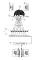
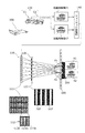
- FIG. 15 is a diagram showing an outline of a conventional stereoscopic video display method using a two-viewpoint parallax barrier method.
- a subject 300 is photographed from different viewpoints by a camera 130 composed of two cameras C1 and C2, and a right eye image (right eye image) X1 and a left eye image (left eye image) X2 are obtained. get.
- the two videos of the acquired right-eye video X1 and left-eye video X2 are synthesized by the format conversion unit 140, and the synthesized video is displayed on the image display unit 110.
- the composite image displayed on the image display unit 110 is separated into the right-eye video X1 and the left-eye video X2 by the image separation unit 120, and is observed as a stereoscopic video.
- the image display unit 110 is a liquid crystal display or a plasma display, and includes a display unit 111 in which a plurality of pixels 112 are arranged in a matrix.
- each of the plurality of pixels 112 includes three subpixels corresponding to red (R), green (G), and blue (B) (a red subpixel 113R, a green subpixel 113G, and a blue subpixel).
- Pixel 113B The plurality of sub-pixels configured in this manner are divided into a plurality of right-eye sub-pixels that display the right-eye video X1 and a plurality of left-eye sub-pixels that display the left-eye video X2.
- the right-eye sub-pixel is denoted by “1”
- the left-eye sub-pixel is denoted by “2”
- an image separation unit 120 is disposed on the front surface of the image display unit 110.
- the image separating unit 120 includes a parallax barrier 121 in which an opening 122 that transmits light and a light shielding unit 123 that blocks light are alternately formed.
- the opening part 122 and the light shielding part 123 in the parallax barrier 121 are only for the right-eye image X1 by the right eye (first viewpoint P1) when the observer (user) 200 in the image observation area 100 observes from a predetermined position. Is observed, and only the left-eye image X2 is observed by the left eye (second viewpoint P2).
- the observer 200 in the video observation area 100 places the head at a predetermined position (normal viewing position), so that the right eye Since the eye image X1 is incident and the left eye image X2 is incident on the left eye, a stereoscopic image can be recognized (see Patent Document 1).
- the shape of the parallax barrier 121 in the image separation unit 120 described above is the same in the shape of each subpixel corresponding to each color component (R, G, and B) constituting one pixel, and is uniform in one pixel. It is produced corresponding to the arranged image display unit 110. Accordingly, in the image display unit 110, when the shapes of the subpixels corresponding to R, G, and B constituting one pixel are not the same, or when the subpixels are not uniformly arranged in one pixel, The color balance of the right-eye video X1 or the left-eye video X2 separated by the image separation unit 120 is lost, and the image quality deteriorates.
- the present invention solves such a problem, and an object of the present invention is to provide a video display method, a video display panel, and a video display device that suppress deterioration of the image quality of a stereoscopic video.
- a video display panel includes an image display that includes a plurality of pixels arranged in a horizontal direction and a vertical direction, and displays a composite image including a plurality of different images. And a composite image displayed on the image display unit by an opening that transmits light and a light-blocking unit that blocks light, which are arranged opposite to the image display unit and alternately arranged in the horizontal direction.
- Each of the plurality of pixels is composed of a plurality of sub-pixels each having a light-emitting region, and the plurality of sub-pixels in one pixel are
- the opening is not an equal size of the pixel, but the opening opens obliquely with respect to the vertical direction, and the boundary line between the opening and the light shielding portion connects the centroids of adjacent subpixels.
- a plurality of subpixels in one pixel are formed when each of the shapes of a plurality of subpixels constituting one pixel is not the same or when the subpixels are not uniformly arranged in one pixel. Even when the size is not equal to one pixel, deterioration in image quality can be suppressed.
- FIG. 1 is a diagram showing an outline of a video display method according to Embodiment 1 of the present invention.
- FIG. 2 is a diagram showing the configuration of the video display panel according to Embodiment 1 of the present invention.
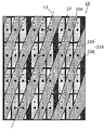
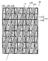
- FIG. 3A is a diagram schematically showing the relationship between the image display unit and the image separation unit in the video display panel according to Embodiment 1 of the present invention (how the video is viewed from the first viewpoint P1).
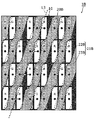
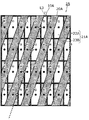
- FIG. 3B is a diagram schematically showing the relationship between the image display unit and the image separation unit in the video display panel according to Embodiment 1 of the present invention (how the video is viewed from the second viewpoint P2).
- FIG. 4 is an enlarged view showing an area for three pixels in the horizontal direction in the video display panel shown in FIG. 3A.
- FIG. 5A is a diagram schematically showing a relationship between the image display unit and the image separation unit in the video display panel according to the first modification of the first embodiment of the present invention (how the video is seen at the first viewpoint P1) ).
- FIG. 5B is a diagram schematically showing a relationship between the image display unit and the image separation unit in the video display panel according to the first modification of the first embodiment of the present invention (how the video is viewed at the second viewpoint P2) ).
- FIG. 6A is a diagram schematically showing a relationship between an image display unit and an image separation unit in a video display panel according to Modification 2 of Embodiment 1 of the present invention (how an image is viewed at the first viewpoint P1) ).
- FIG. 6B is a diagram schematically showing the relationship between the image display unit and the image separation unit in the video display panel according to Modification 2 of Embodiment 1 of the present invention (how the video is viewed at the second viewpoint P2) ).
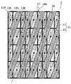
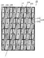
- FIG. 7A is a diagram schematically showing the relationship between the image display unit and the image separation unit in the video display panel according to Embodiment 2 of the present invention (how the video is viewed from the first viewpoint P1).
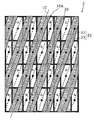
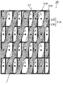
- FIG. 7B is a diagram schematically showing the relationship between the image display unit and the image separation unit in the video display panel according to Embodiment 2 of the present invention (how the video is viewed at the second viewpoint P2).
- FIG. 7A is a diagram schematically showing the relationship between the image display unit and the image separation unit in the video display panel according to Embodiment 2 of the present invention (how the video is viewed from the first viewpoint P1).
- FIG. 7B is a diagram schematically showing the relationship between the image display unit and the image separation unit in the video display panel according to Embod
- FIG. 8A is a diagram schematically showing the relationship between the image display unit and the image separation unit in the video display panel according to the first modification of the second embodiment of the present invention (how the video is viewed at the first viewpoint P1) ).
- FIG. 8B is a diagram schematically showing the relationship between the image display unit and the image separation unit in the video display panel according to the first modification of the second embodiment of the present invention (how the video is viewed at the second viewpoint P2) ).
- FIG. 9A is a diagram schematically showing the relationship between the image display unit and the image separation unit in the video display panel according to the second modification of the second embodiment of the present invention (how the video is seen at the first viewpoint P1) ).
- FIG. 9B is a diagram schematically showing the relationship between the image display unit and the image separation unit in the video display panel according to the second modification of the second embodiment of the present invention (how the video is seen at the second viewpoint P2) ).
- FIG. 10 is a diagram showing a schematic configuration of a video display apparatus according to Embodiment 3 of the present invention.
- FIG. 11A is a diagram schematically showing the relationship between the image display unit and the image separation unit in the first conventional video display panel (how the video is seen at the first viewpoint P1).
- FIG. 11B is a diagram schematically showing the relationship between the image display unit and the image separation unit in the video display panel according to the first modification of the present invention (how the video is seen at the first viewpoint P1).
- FIG. 12A is a diagram schematically illustrating the relationship between the image display unit and the image separation unit in the second conventional video display panel (how the video is viewed at the first viewpoint P1).
- FIG. 12B is a diagram schematically illustrating the relationship between the image display unit and the image separation unit in the video display panel according to the second modification of the present invention (how the video is viewed from the first viewpoint P1).
- FIG. 13 is a diagram schematically showing the relationship between the image display unit and the image separation unit in the video display panel according to Modification 3 of the present invention (how the video is seen at the first viewpoint P1).
- FIG. 14 is a diagram schematically illustrating the relationship between the image display unit and the image separation unit in the video display panel according to the fourth modification of the present invention (how the video is viewed from the first viewpoint P1).
- FIG. 15 is a diagram showing an outline of a conventional general stereoscopic video display method.
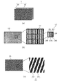
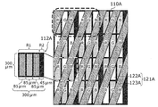
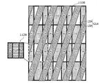
- FIG. 16A shows an example of a case where a plurality of subpixels in one pixel are not equal in size to the one pixel, a display unit in an image display unit in which a bus bar is formed, and a parallax barrier in a conventional image separation unit. Is a diagram schematically showing the relationship (how the video is viewed from the first viewpoint P1).
- FIG. 16B shows an example in which a plurality of subpixels in one pixel are not equal in size to the one pixel, a display unit in an image display unit in which a bus bar is formed, and a parallax barrier in a conventional image separation unit.
- FIG. 17 is an enlarged view showing a region for three pixels in the horizontal direction in the video display panel shown in FIG. 16A.
- FIG. 18 shows an image display in which a plurality of subpixels in one pixel are not equal in size to the one pixel, and the subpixels in one pixel include subpixels having different sizes as another example. It is a figure which shows typically the relationship between the display part in a part, and the parallax barrier in the conventional image separation part.
- the observer 200 uses the right-eye video X1 and the left-eye video corresponding to the two viewpoints of the first viewpoint P1 (right eye) and the second viewpoint P2 (left eye), respectively.
- the subject 300 is stereoscopically viewed by viewing the right-eye video X1 corresponding to the first viewpoint P1 with the right eye and the left-eye video X2 corresponding to the second viewpoint P2 with the left eye. Can do.
- the pixel structure in the display unit 111 of the image display unit 110 is such that one pixel 112 has three subpixels corresponding to three colors of R, G, and B (a red subpixel 113R, a green subpixel 113G, and a blue color).
- Sub-pixels 113B), and the sub-pixels have the same shape and are equally divided into one pixel.
- the opening has an opening continuous in a direction having a predetermined angle with respect to the vertical direction.
- a plurality of structures having a predetermined interval in the horizontal direction are used. That is, a parallax barrier having an opening (or a light-shielding portion) having an oblique line shape (slant type) may be used. This is because, in the image separation unit 120 used in a conventional autostereoscopic 3D display device (two parallax), a plurality of subpixels in the image display unit 110 are alternately used for the left eye and the right eye in the horizontal direction.
- the interval between the openings is equal to the horizontal size of each sub-pixel.
- the shape and arrangement of the sub-pixels corresponding to R, G, and B constituting one pixel are often uniform.
- the plurality of sub-pixels that are configured do not have a size obtained by equally dividing the one pixel.
- the inventor of the present application uses the above-described slant-type parallax barrier for an image display unit having a pixel configuration in which a plurality of sub-pixels constituting one pixel are not equally divided. It has been found that the image quality of the stereoscopic video deteriorates when the image is applied.
- an organic EL display device is used as an image display unit.
- a transparent electrode such as ITO (Indium Tin Oxide) is used as an electrode (upper electrode) disposed closer to the viewer than the light emitting layer.
- ITO Indium Tin Oxide
- the reason for using the transparent electrode is to prevent a decrease in the amount of light emitted from the light emitting layer so as not to deteriorate the image quality.
- the transparent electrode made of ITO or the like has a higher resistance than the metal wiring, a voltage drop occurs and it is difficult to stably supply power to the entire panel.
- the influence of the voltage drop is increasing due to the recent enlargement of the panel. For this reason, the voltage drop is suppressed by using a low-resistance metal electrode (bus bar) in combination as the auxiliary wiring, and power can be stably supplied to the entire display panel.
- a low-resistance metal electrode bus bar
- a bus bar made of a low-resistance metal material is not transparent but has a light shielding property, it is necessary to form a bus bar in a region different from the light emitting region.
- a light shielding region between light emitting regions for example, a bus bar is formed corresponding to the above.
- FIGS. 16A and 16B are diagrams schematically illustrating a relationship between a display unit in an image display unit in which a bus bar is formed and a parallax barrier in a conventional image separation unit.
- 16A shows how the video is viewed at the first viewpoint P1
- FIG. 16B shows how the video is viewed at the second viewpoint P2.
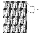
- one pixel 112A in an image display unit 110A including a display unit on which a bus bar is formed, one pixel 112A includes a sub-pixel region R1, which is a region where three RGB sub-pixels are formed, It comprises a bus bar forming region R2 which is a light shielding region for forming a bus bar. That is, a bus bar exists in the light shielding region between the pixels 112A adjacent in the horizontal direction, and the interval between the blue sub-pixel and the red sub-pixel is wider than the interval between the other sub-pixels.
- the RGB sub-pixels are non-uniformly arranged in one pixel due to the arrangement of the bus bars. That is, the three RGB sub-pixels in one pixel are not equal in size to the one pixel.
- the image separation unit that generates the parallax barrier 121A of the slant opening 122A (the light shielding unit 123A) is applied to the image display unit 110A including the display unit on which the bus bar is formed
- the first viewpoint P1 and The images viewed from the second viewpoint P2 are images as shown in FIGS. 16A and 16B, respectively.
- the subpixels corresponding to the right-eye image are dotted with dotted dots
- the subpixels corresponding to the left-eye image are outlined.
- the image viewed from the first viewpoint P1 is originally an image including only the sub-pixel displaying the right-eye image.
- the image viewed from the first viewpoint P1 is originally an image including only the sub-pixel displaying the right-eye image.
- the video viewed from the second viewpoint P2 is originally a video by only the sub-pixel displaying the left-eye video, but corresponds to the left-eye video as shown in FIG. 16B. It was found that in addition to the subpixels (white cells), there are many subpixels (scattered cells) corresponding to the video for the right eye.
- FIGS. 16A and 16B a large amount of left-eye video is mixed in a video that is desired to be viewed as a right-eye video, and conversely, a right eye is required for a video that is desired to be viewed as a left-eye video. It turns out that a lot of video for use gets mixed. For example, when attention is paid to the area surrounded by the broken line shown in FIGS. 16A and 16B, it can be seen that unnecessary video is mixed and the image quality as a stereoscopic video is deteriorated.
- FIG. 17 is an enlarged view showing a region for three pixels in the horizontal direction in the video display panel shown in FIG. 16A.
- the video viewed from the first viewpoint P1 is a video that includes many of the sub-pixels (white cells) corresponding to the video for the left eye.
- This also confirms that the area ratios of the RGB sub-pixels in the right-eye video are not the same. That is, it can be seen that the RGB color balance is broken for each sub-pixel assigned to the RGB of the right-eye video when viewed from the first viewpoint P1.
- the black part of the light shielding part 123A of the image separation part 120A interferes with the black part of the image display part 110A (black matrix or light shielding area of the non-illuminated part), and colored moire occurs. Therefore, it can be seen that the image quality deteriorates when viewed as the right-eye video or the left-eye video.
- the video for the left eye is mixed in the video to be viewed as the video for the right eye, and conversely, the video for the video to be viewed as the video for the left eye is mixed.
- the image quality as a stereoscopic video deteriorates because the video for the eye is mixed.
- the color balance of RGB is generated, and colored moire (color moire) is generated, which deteriorates the image quality.
- FIG. 18 is a diagram schematically illustrating a relationship between a display unit in an image display unit in which subpixels of different sizes are included in one subpixel and a parallax barrier in a conventional image separation unit.
- FIG. 18 shows how the video is viewed at the first viewpoint P1.
- the width (shape) of each of the R, G, and B sub-pixels may be changed, which also results in a non-uniform pixel structure.
- an image viewed from the first viewpoint P1 is an image as illustrated in FIG.
- the image viewed from the first viewpoint P1 is an image including only the sub-pixel displaying the right-eye image.
- the sub-pixel corresponding to the right-eye image is displayed. It was found that in addition to (scattered cells), there are many sub-pixels (outlined cells) corresponding to the left-eye image.
- the same can be said for the video viewed from the second viewpoint P2, as in FIG. 16B.
- the video to be viewed as the right-eye video includes a large amount of the left-eye video, and conversely, the video to be viewed as the left-eye video.
- the inventor of the present application It was found that the image quality of the stereoscopic image deteriorates due to the color balance of the image for the eye and the image for the left eye being broken or color moire.
- the inventor of the present application designed the opening shape of the opening of the parallax barrier of the image separation unit depending on the position of the center of gravity of each subpixel, thereby causing a loss of color balance.
- image quality deterioration can be suppressed by suppressing color moire.
- a video display method includes a plurality of pixels arranged in a horizontal direction and a vertical direction, and a plurality of different images.
- the image display unit includes an image display unit that displays a combined image, an opening that is disposed to face the image display unit and alternately transmits light in the horizontal direction, and a light-blocking unit that blocks light.
- a method of displaying an image using the image separation unit that separates the composite image displayed on a part into the plurality of different images, wherein each of the plurality of pixels includes a plurality of subpixels each having a light emitting region.
- Each of the plurality of sub-pixels in one pixel is not equally divided into one pixel, and the opening is opened obliquely with respect to the vertical direction.
- the continuous line of the line connecting the centroids of the adjacent subpixels or the continuous line of the line connecting the centroids of the adjacent light emitting areas is translated, or the centroid of the adjacent subpixels
- the video is displayed as a continuous line connecting the midpoints or a continuous line connecting the midpoints of the centers of gravity of adjacent light emitting areas.
- An image display panel includes an image display unit that includes a plurality of pixels arranged in a horizontal direction and a vertical direction, and displays a composite image including a plurality of different images, and the image display unit.
- the composite image displayed on the image display unit is converted into the plurality of different images by the light-transmitting openings and the light-shielding portions that are arranged alternately in the horizontal direction.
- each of the plurality of pixels is configured by a plurality of subpixels each having a light emitting region, and the plurality of subpixels in one pixel equally divides the one pixel.
- the opening not the size, opens obliquely with respect to the vertical direction
- the boundary line between the opening and the light-shielding portion is a continuous line of lines connecting adjacent gravity centers of adjacent subpixels or adjacent to each other. It is parallel to a continuous line connecting the centroids of the light areas, or a continuous line connecting the centroids of the adjacent subpixels, or a continuous line connecting the centroids of the adjacent light emitting areas. It is characterized by that.
- the boundary line is a continuous line connecting the centroids of the subpixels adjacent in the oblique direction or a continuous line connecting the centroids of the light emitting areas adjacent in the oblique direction. May be translated in the vertical direction.
- the continuous line connecting the centroids of the subpixels adjacent in the oblique direction or the continuous line connecting the centroids of the light emitting regions adjacent in the oblique direction is It may be bent so that the amount of light from the plurality of sub-pixels displaying each of a plurality of different images increases.
- the boundary line is a continuous line connecting the midpoints of the centroids of the subpixels adjacent in the horizontal direction or the centroid of the light emitting region adjacent in the horizontal direction. It may be a continuous line connecting the midpoints.
- the line connecting the midpoints of the centroids of the subpixels adjacent in the horizontal direction or the line connecting the midpoints of the centroids of the light emitting areas adjacent in the horizontal direction may be a straight line.
- a line connecting the midpoints of the centroids of the subpixels adjacent in the horizontal direction or a line connecting the midpoints of the centroids of the light emitting areas adjacent in the horizontal direction is the plurality of the plurality of different images displaying each of the plurality of different images. It may be bent so that the amount of light from the sub-pixel increases.
- each of the plurality of pixels includes a region composed of the plurality of sub-pixels and a region different from the plurality of sub-pixels. May be.
- the region different from the plurality of subpixels can be a region for forming an auxiliary wiring.
- the plurality of sub-pixels correspond to different colors, and the sub-pixel corresponding to one color among the plurality of sub-pixels in the one pixel and the one sub-pixel. Sub-pixels corresponding to colors different from the color may be configured to have different sizes.
- an area ratio of each color component of the plurality of subpixels visible from the opening is substantially equal to an area ratio of each color component of the plurality of subpixels included in the pixel. Preferably they are the same.
- the image separation unit may be configured to change an opening shape of the opening.
- the image separation unit may be configured to completely transmit the composite image without the light shielding unit.
- each of the plurality of subpixels in the one pixel may correspond to a different color.
- the video display device is capable of viewing both and / or one of a stereoscopic image and a 2D image by the above-described video display panel.
- the video display panel according to the present invention can be realized as a video display device capable of viewing both or one of a stereoscopic image and a 2D image.
- Embodiment 1 First, a video display method, a video display panel, and a video display device according to Embodiment 1 of the present invention will be described with reference to the drawings.
- FIG. 1 is a diagram showing an outline of a video display method according to Embodiment 1 of the present invention that can be stereoscopically viewed with the naked eye.
- a stereoscopic image can be viewed from signals (right-eye video X1 and left-eye video X2) at two viewpoints, a first viewpoint P1 (right eye) and a second viewpoint P2 (left eye).
- the principle of (2 parallax) is shown.
- the observer 200 in the video display area (viewing position) 100 sees the right-eye video X1 that is the signal of the first viewpoint P1 out of the signals of the two viewpoints with the right eye, and It shows that a stereoscopic video can be observed by viewing the left-eye video X2 as a signal with the left eye.
- the right-eye subpixel in the image display unit 10 is represented as “1”
- the left-eye subpixel is represented as “2”
- the right-eye video and the left-eye video are displayed.
- An example of alternately displaying is shown.
- FIG. 2A and 2B are diagrams showing a configuration of the video display panel according to Embodiment 1 of the present invention, in which FIG. 2A is a perspective view showing a schematic configuration of the video display panel, and FIG. 2B is a schematic configuration of an image display unit.
- FIG. 2C is a diagram illustrating a schematic configuration of the image separation unit.
- the video display panel 1 is a parallax barrier type stereoscopic video display panel that allows an observer (viewer) 200 to stereoscopically view with naked eyes, as shown in FIG.
- the image display unit (video display unit) 10 and the image separation unit (video separation unit) 20 disposed to face the image display unit 10 are provided.
- the image separation unit 20 is arranged on the front side (observer side) of the image display unit 10 at a predetermined distance from the image display unit 10.
- a flat panel display such as a liquid crystal display, a plasma display, an organic EL (Electro Luminescence) display, or an inorganic EL display can be used.
- an organic EL display is used.
- a liquid crystal shutter panel can be used as the image display unit 110.
- An organic EL display is, for example, on a drive circuit layer (planarization layer) including a thin film transistor formed on a glass substrate, between a lower electrode (anode), an upper electrode (cathode), and a lower electrode and an upper electrode.
- the formed organic light emitting layer (light emitting portion), the partition wall (bank) partitioning the organic light emitting layer, the sealing resin layer formed on the upper electrode, and the glass substrate formed on the sealing resin layer And are arranged.
- the lower electrode, the upper electrode, and the organic light emitting layer are organic EL elements.
- the upper electrode is a solid electrode formed in common for all subpixels.
- the lower electrode is formed in an island shape for each subpixel.
- the image display unit 10 includes a display unit (video display surface) 11 including a plurality of pixels 12 arranged in a matrix in the horizontal direction and the vertical direction.
- the display unit 11 displays a combined image in which a plurality of different images are combined as a predetermined image such as a still image or a moving image.
- the display unit 11 has a three-dimensional display three-dimensional display that is a composite image of the right-eye video that is the signal of the first viewpoint P1 and the left-eye video that is the signal of the second viewpoint P2. An image is displayed.
- the display unit 11 displays not only a three-dimensional image but also a two-dimensional image.
- Each of the plurality of pixels (main pixels) 12 has a plurality of sub-pixels (sub-pixels) corresponding to different colors.
- each pixel 12 in the present embodiment in addition to a plurality of subpixels, there is a region (busbar forming region) for forming an auxiliary wiring (busbar) as a region different from the plurality of subpixels. That is, each pixel 12 includes an area configured by a plurality of subpixels and a bus bar forming area. Accordingly, each of the plurality of sub-pixels in one pixel is not sized equally.
- each pixel 12 includes a red sub-pixel 13R having a red light-emitting region that emits red light, a green sub-pixel 13G having a green light-emitting region that emits green light, and A subpixel region R1 that is a region where three subpixels are formed, a blue subpixel 13B having a blue light emitting region that emits blue light, and a bus bar formation region R2 that is a light shielding region 14 made of a black matrix or the like. It is configured.
- the RGB subpixels have the same size (horizontal width).
- the auxiliary wiring is electrically connected to the upper electrode in order to suppress the influence of the voltage drop due to the upper electrode (transparent electrode).
- each color light-emitting area is surrounded by a non-light-emitting area (light-shielding area) made of a black matrix. That is, a light-shielding region (non-light-emitting region) made of a black matrix is formed between adjacent color light-emitting regions in order to prevent color mixing between RGB. Further, the width of the black matrix in the bus bar forming region is formed to be larger than the width of the black matrix between the light emitting regions, and the wide light shielding region 14 is formed in pixel units. Further, in the horizontal direction of the display unit 11, a red subpixel 13R, a green subpixel 13G, and a blue subpixel 13B are repeatedly arranged in this order. Are repeatedly arranged.
- the image separation unit 20 selectively separates the composite image so that at least one of the images included in the composite image displayed on the image display unit 10 can be visually recognized. For example, when a three-dimensional image is displayed on the display unit 11 of the image display unit 10, the parallax for separating the three-dimensional image into a right-eye video and a left-eye video for stereoscopic display. A barrier 21 is generated.
- the parallax barrier 21 is configured to selectively transmit light by controlling passage and blocking of light, and includes a plurality of openings 22 that transmit light and a plurality of light shielding units 23 that shield light. Are arranged alternately in the horizontal direction.
- the composite image displayed on the image display unit 10 is separated into a plurality of different images by the opening 22 and the light shielding unit 23.
- a composite image composed of a three-dimensional image displayed on the image display unit 10 is separated into a right-eye video and a left-eye video.
- Each opening 22 is a slit having a certain opening width and opening in a direction having a predetermined angle with respect to the vertical direction (vertical direction in the display unit 11). That is, each opening 22 is continuously opened in an oblique direction with respect to the vertical direction.
- Each light shielding portion 23 is a barrier portion having a predetermined angle with respect to the vertical direction so as to have a constant light shielding width and the same inclination angle as the opening 22.
- the opening 22 is a region between adjacent light shielding portions 23.
- the parallax barrier 21 in the present embodiment is a slant type having an oblique line shape, and the opening 22 and the light-shielding portion 23 are both oblique stripes that are inclined to the right (downward to the left). It is formed in a shape.
- the opening width of the opening 22 in the parallax barrier 21 (the light blocking width of the light blocking portion 23) is not constant in the tilt direction but is configured to change.
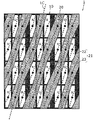
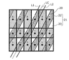
- FIGS. 3A and 3B are diagrams schematically showing a relationship between the image display unit and the image separation unit in the video display panel according to Embodiment 1 of the present invention.
- 3A and 3B show a state viewed from the direction perpendicular to the video display surface
- FIG. 3A shows how the video is seen at the first viewpoint P1
- FIG. 3B shows the second viewpoint. It represents how the image is viewed at P2.
- the subpixels corresponding to the right-eye image are dotted with hatching
- the subpixels corresponding to the left-eye image are outlined.
- the right-eye image and the left-eye image are assigned to the plurality of pixels 12 in subpixel units, and the left-eye subpixel and the right-eye subpixel are horizontally aligned. And the left-eye subpixels and the right-eye subpixels are assigned alternately in the vertical direction.
- the opening shape of the opening 22 of the parallax barrier 21 in the image separation unit 20 (or the light shielding shape of the light shielding unit 23).
- the predetermined position of each sub-pixel in the plurality of pixels 12 of the image display unit 10 is defined as a reference.
- the boundary line between the opening 22 and the light shielding unit 23 in the image separation unit 20 is a plurality of subpixels (the red subpixel 13R, the green subpixel 13G, and the blue subpixel) in the entire display unit 11. 13B), the continuous line connecting the predetermined positions of the subpixels adjacent to each other in the diagonal direction is translated in the vertical direction (vertical direction in the display unit 11: vertical direction on the paper surface).
- the opening shape is designed.
- the boundary line between the opening 22 and the light shielding portion 23 corresponds to the edge shape of the opening 22 in the longitudinal direction or the edge shape of the light shielding portion 23 in the longitudinal direction.
- the predetermined position of the subpixel is a position determined in advance by the shape of the subpixel, and is the same position in each subpixel. In the present embodiment, the predetermined position of the subpixel is the center of gravity of the subpixel. 3A and 3B, when the shape of the subpixel is a quadrangle, the predetermined position may be a position of the center of gravity indicating the center of the subpixel.
- the predetermined position will be described as the center of gravity of the subpixel.
- the center of gravity of each subpixel is indicated by a black circle ( ⁇ )
- a continuous line of lines connecting the centers of gravity of subpixels adjacent in an oblique direction is indicated by a broken line.
- the boundary line of the opening part 22 and the light-shielding part 23 is a thing which translated the continuous line of the line which connects the gravity center of the subpixel which adjoins diagonally in the orthogonal
- the boundary line between the opening 22 and the light-shielding part 23 is parallel to a continuous line connecting the centroids of the subpixels adjacent in the oblique direction.
- a line segment connecting the centroids of the subpixels adjacent in the oblique direction that is, a line extending from the centroid of one of the subpixels adjacent in the oblique direction to the centroid of the other subpixel extends across the light shielding region 14
- the inclination angle with respect to the vertical direction differs depending on whether or not there is no straddle. This is because the length of the line segment connecting the centers of gravity of the subpixels adjacent in the oblique direction when straddling the light shielding region 14 is increased by the width of the light shielding region 14 in the horizontal direction.
- the boundary line with the light shielding portion 23a on one side (left side) of the opening 22a is defined as L1 (first parallel line).
- the boundary between the opening 22a and the light shielding portion 23b on the other side (right side) is L2 (second parallel line), and the center of gravity of the subpixels adjacent to the opening 22a in the diagonal direction is a single straight line.
- the continuous line of the connecting lines is LC
- the boundary lines L1 and L2 in the opening 22a are obtained by translating the continuous line LC connecting the centers of gravity in the vertical direction (Sh / 2) respectively by Sh / 2. It is configured.
- Sh represents the vertical length of the subpixel.
- the other openings in FIG. 3A are configured in the same manner as the opening 22a.
- the opening 22 in FIG. 3B has the same configuration as the opening in FIG. 3A.
- the ratio of sub-pixels (outlined cells) on which the left-eye video is displayed increases. That is, in the present embodiment, it is possible to reduce the ratio of the right-eye video mixed in the video that is desired to be viewed as the left-eye video. Thereby, deterioration of the image quality as a three-dimensional image can be suppressed.
- FIG. 4 is an enlarged view showing an area for three pixels in the horizontal direction in the video display panel shown in FIG. 3A.
- the ratio of the sub-pixels (white cells) that display the left-eye image is reduced compared to the case of FIG. 14, and the sub-pixels (scattered cells) that display the right-eye image.
- the area ratio of each of the red subpixel 13R, the green subpixel 13G, and the blue subpixel 13B is substantially the same (R: G: B ⁇ 1: 1: 1).
- the boundary line between the opening 22 and the light shielding unit 23 in the image separation unit 20 is Since it is parallel to a continuous line connecting the centroids of adjacent sub-pixels in the display unit 11 of the display unit 10, the right-eye video and the left image observed by the observer 200 from the first viewpoint P1 and the second viewpoint P2 It can suppress that the other image
- the image separation unit 20 is configured by a slant parallax barrier 21 as in the present embodiment, the light shielding unit 23 of the parallax barrier 21 and the light shielding region 14 (black matrix or the like) of the image display unit 10.
- the video display panel 1 according to the present embodiment it is possible to suppress the uneven color balance, and thus suppress the generation of colored moire. be able to.
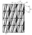
- FIGS. 5A and 5B are diagrams schematically showing the relationship between the image display unit and the image separation unit in the video display panel according to Modification 1 of Embodiment 1 of the present invention.
- 5A shows how the video is viewed at the first viewpoint P1
- FIG. 5B shows how the video is viewed at the second viewpoint P2.
- the video display panel 1A according to this modification is different from the video display panel 1 according to the first embodiment in the configuration of the parallax barrier in the image separation unit.
- the configuration other than the image separation unit is the same as that of the video display panel 1 according to the first embodiment. Therefore, in FIGS. 5A and 5B, the same components as those in FIGS. 3A and 3B are denoted by the same reference numerals, and detailed description thereof is omitted or simplified.
- the opening shape of the opening 22A (the light blocking shape of the light blocking portion 23A) in the parallax barrier 21A of the image separation unit 20A is the first embodiment.
- the center of gravity of the sub-pixels in the image display unit 10 is defined as a reference.
- the boundary line between the opening 22A and the light-shielding unit 23A is defined by a plurality of sub-pixels in the entire display unit 11.
- the opening shape of the opening 22A is designed to be a continuous line connecting the midpoints of the centers of gravity of the subpixels adjacent in the horizontal direction.
- the plurality of openings 22A and the plurality of light shielding portions 23A are alternately arranged in the horizontal direction.
- Each opening 22A opens continuously in an oblique direction with respect to the vertical direction, and each light shielding portion 23A has a predetermined angle with respect to the vertical direction so as to have the same inclination angle as the opening 22A. Therefore, also in this modification, the parallax barrier 21A is a slant type.
- the center of gravity of each subpixel is indicated by a black circle ( ⁇ ), and the midpoint of the center of gravity of the subpixels adjacent in the horizontal direction is indicated by a white square ( ⁇ ).
- a continuous line of lines connecting the midpoints ( ⁇ ) of the center of gravity with a single straight line is indicated by a broken line.
- the boundary line between the opening 22A and the light shielding part 23A is a continuous line L3 itself that connects the midpoints of the centers of gravity of the subpixels adjacent in the horizontal direction with a straight line.
- the area ratios of the red subpixel, the green subpixel, and the blue subpixel are substantially the same (R: G: B ⁇ 1: 1: 1), and the RGB color balance is biased. It can be seen that is greatly improved.
- the same effects as those of the first embodiment can be obtained. That is, it is possible to suppress the other video from being mixed into one of the right-eye video and the left-eye video observed by the observer 200 from the first viewpoint P1 and the second viewpoint P2. As a result, deterioration in image quality can be suppressed, so that a high-quality stereoscopic image can be displayed. Also in this modified example, since the uneven color balance can be suppressed, the generation of colored moire can be suppressed.
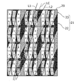
- FIGS. 6A and 6B are diagrams schematically showing a relationship between an image display unit and an image separation unit in a video display panel according to Modification 2 of Embodiment 1 of the present invention.
- 6A shows how the video is viewed at the first viewpoint P1
- FIG. 6B shows how the video is viewed at the second viewpoint P2.
- the video display panel 1B according to this modification is different from the video display panel 1 according to the first embodiment in the configuration of the parallax barrier in the image separation unit.
- the configuration other than the image separation unit is the same as that of the video display panel 1 according to the first embodiment. Accordingly, in FIGS. 6A and 6B, the same components as those in FIGS. 3A and 3B are denoted by the same reference numerals, and detailed description thereof is omitted or simplified.
- the opening shape of the opening 22B (the light shielding shape of the light shielding portion 23B) in the parallax barrier 21B of the image separation unit 20B is the first embodiment.
- the center of gravity of the sub-pixels in the image display unit 10 is defined as a reference, but in this modification, the boundary line between the opening 22B and the light-shielding unit 23B is defined by a plurality of sub-pixels in the entire display unit 11. Of these, continuous lines connecting the midpoints of the centroids of adjacent subpixels in the horizontal direction so that the amount of light from multiple subpixels that display either the right-eye image or the left-eye image increases.
- the opening shape of the opening 22B is designed to be a line obtained by bending a part of the continuous line. That is, the boundary line between the opening 22B and the light shielding part 23B in this modification is based on the boundary line between the opening 22A and the light shielding part 23A in Modification 1, that is, the center of gravity of the subpixels adjacent in the horizontal direction. A periodic or aperiodic pattern is added based on a continuous line L3 of lines connecting the middle points with straight lines.
- the boundary line between the opening 22B and the light-shielding portion 23B in the present modification is such that the amount of light from a plurality of sub-pixels displaying either the right-eye image or the left-eye image increases.
- the continuous line L3 is bent, and a jagged pattern is further added based on the opening shape of the opening 22A shown in FIGS. 5A and 5B.
- each opening 22B opens continuously in a stepwise manner in an oblique direction with respect to the vertical direction, and each light shielding portion 23B continues in a stepwise manner in an oblique direction with respect to the vertical direction, like the opening 22A. Is formed.
- the center of gravity of each subpixel is indicated by a black circle ( ⁇ )
- the midpoint of the center of gravity of adjacent subpixels is indicated by a white square ( ⁇ )
- a continuous line connecting the midpoints ( ⁇ ) of the center of gravity is indicated by a broken line.
- the boundary line between the opening 22B and the light-shielding part 23B is based on the continuous line L3 of the lines connecting the midpoints of the centroids of the subpixels adjacent in the horizontal direction. It has a structure that protrudes from side to side with ⁇ ).
- the continuous line L3 in the upper part of the midpoint ( ⁇ ) of the center of gravity in one pixel is bent so as to protrude in the left direction of the page, and the lower side of the midpoint ( ⁇ ) of the center of gravity in one pixel.
- the continuous line L3 of the part is bent so as to protrude in the right direction of the page.
- the left-eye video is displayed for the video observed from the first viewpoint P1 as the right-eye video as compared to the case of FIG. 5A. It can be seen that the proportion of unnecessary sub-pixels (outlined cells) decreases and the proportion of necessary sub-pixels (scattered cells) on which the right-eye video is displayed increases.
- the image observed from the second viewpoint P2 as the left-eye image is further compared with the case of FIG. It can be seen that the ratio of the sub-pixels (outlined cells) in which the left eye image is displayed increases as the ratio of the scattered cells) decreases.
- the ratio of the other image mixed in the image to be visually recognized as the left-eye image or the right-eye image can be further reduced as compared with Modification 2.
- the video display panel 1B according to the present modification as compared with the first embodiment and the modification 1, the video for the right eye and the left observed by the observer 200 from the first viewpoint P1 and the second viewpoint P2. It is possible to further suppress the other image from being mixed into one of the ophthalmic images. As a result, a higher quality stereoscopic image can be displayed.
- the configuration of the light shielding unit 23B in the image separation unit 20B of the present modification can remarkably suppress the occurrence of moire due to interference between the light shielding unit 23 and the light shielding region 14 of the image display unit 10. As a result, the generation of colored moire can be effectively suppressed.
- FIGS. 7A and 7B are diagrams schematically showing the relationship between the image display unit and the image separation unit in the video display panel according to Embodiment 2 of the present invention.
- FIG. 7A shows how the video is viewed at the first viewpoint P1
- FIG. 7B shows how the video is viewed at the second viewpoint P2.
- the pixel configuration in the image display unit of the video display panel 1 is different from that in the first embodiment.
- the pixel configuration of the display unit 11A in the image display unit 10A is that a plurality of sub-pixels in one pixel are equally divided.
- the size is not the same as that of the first embodiment, a subpixel corresponding to one color among a plurality of subpixels in one pixel and another subpixel corresponding to a color different from the one color are the same.
- the difference from Embodiment 1 is that the size of the pixel is different.
- the pixel sizes in the horizontal direction of the RGB sub-pixels constituting one pixel are different. More specifically, as shown in FIGS. 7A and 7B, the horizontal pixel size of the green sub-pixel 13G at the center of the pixel is different from the pixel size of the red sub-pixel 13R and the blue sub-pixel 13B. It is configured.
- the horizontal pixel size of the green sub-pixel 13G is different from the horizontal pixel size of the other sub-pixels, but the red sub-pixel 13R or the blue sub-pixel is different.
- the horizontal pixel size of 13B may be different from the horizontal pixel size of other sub-pixels. 7A and 7B, the red subpixel 13R and the blue subpixel 13B have the same horizontal pixel size, but all the RGB subpixels have different horizontal pixel sizes. You may comprise. Further, in the present embodiment, there is no light shielding region as a bus bar forming region, and the light shielding regions (black matrix) between the light emitting regions of the sub-pixels have the same width.
- the image separation unit 20 in the present embodiment is configured based on the same concept as the image separation unit 20 in the first embodiment shown in FIGS. 3A and 3B. That is, in the image separation unit 20 according to the present embodiment, the boundary line between the opening 22 and the light shielding unit 23 includes a plurality of subpixels (the red subpixel 13R, the green subpixel 13G, and the blue color) in the entire display unit 11. In the subpixel 13B), a continuous line LC connecting predetermined positions of subpixels adjacent in the oblique direction is translated in the vertical direction by Sh / 2.
- the predetermined position is the center of gravity of the sub-pixel, and the boundary line between the opening 22 and the light-shielding part 23 is parallel to a continuous line connecting the centers of gravity of the sub-pixels adjacent in the oblique direction. is there. 7A and 7B, the center of gravity of each subpixel is indicated by a black circle ( ⁇ ).
- the plurality of openings 22 and the plurality of light-shielding portions 23 are alternately arranged in the horizontal direction.
- Each opening 22 opens continuously in an oblique direction with respect to the vertical direction, and each light shielding portion 23 has a predetermined angle with respect to the vertical direction so as to have the same inclination angle as the opening 22. Therefore, also in this embodiment, the parallax barrier 21 is a slant type.
- the same effects as those of the first embodiment can be obtained. That is, it is possible to suppress the other video from being mixed into one of the right-eye video and the left-eye video observed by the observer 200 from the first viewpoint P1 and the second viewpoint P2. As a result, deterioration in image quality can be suppressed, so that a high-quality stereoscopic image can be displayed. Also in this modified example, since the uneven color balance can be suppressed, the generation of colored moire can be suppressed.
- FIGS. 8A and 8B are diagrams schematically showing a relationship between an image display unit and an image separation unit in a video display panel according to Modification 1 of Embodiment 2 of the present invention.
- 8A shows how the video is seen at the first viewpoint P1
- FIG. 8B shows how the video is seen at the second viewpoint P2.
- the video display panel 2A according to this modification is different from the video display panel 2 according to the second embodiment in the configuration of the parallax barrier in the image separation unit.
- the configuration other than the image separation unit is the same as that of the video display panel 1 according to the second embodiment. Therefore, in FIGS. 8A and 8B, the same components as those in FIGS. 7A and 7B are denoted by the same reference numerals, and detailed description thereof is omitted or simplified.
- the opening 22A and the light shielding part 23A in the parallax barrier 21A of the image separation unit 20A are the same as in Modification 1 of the first embodiment. It is structured by way of thinking.
- the opening shape of the opening portion 22A (the light shielding shape of the light shielding portion 23A) in the image separation unit 20A according to this modification example is such that the boundary line between the opening portion 22A and the light shielding portion 23A is adjacent to each other in the horizontal direction among a plurality of subpixels.
- the opening shape of the opening 22A is designed so as to be a continuous line connecting the midpoints of the centroids of the pixels.
- the center of gravity of each subpixel is indicated by a black circle ( ⁇ ), and the midpoint of the center of gravity of the subpixels adjacent in the horizontal direction is indicated by a white square ( ⁇ ).
- a continuous line connecting the midpoints ( ⁇ ) of the center of gravity is indicated by a broken line.
- the boundary line between the opening 22A and the light shielding part 23A is a continuous line L3 itself that connects the midpoints of the centers of gravity of the subpixels adjacent in the horizontal direction with a straight line.
- the aperture / light-shielding balance is improved as compared with the conventional method.
- the opening shape of the opening 22A as shown in this figure, as shown in FIG. 8A, the image observed from the first viewpoint P1 as the right-eye image is compared with the case of FIG.
- the ratio of unnecessary sub-pixels (outlined cells) on which the eye image is displayed decreases, and the ratio of necessary sub-pixels (scattered cells) on which the right-eye image is displayed increases.
- FIGS. 9A and 9B are diagrams schematically showing a relationship between an image display unit and an image separation unit in a video display panel according to Modification 2 of Embodiment 2 of the present invention. Note that FIG. 9A shows how the video is seen at the first viewpoint P1, and FIG. 9B shows how the video is seen at the second viewpoint P2.
- the video display panel 2B according to this modification is different from the video display panel 2 according to the second embodiment in the configuration of the parallax barrier in the image separation unit.
- the configuration other than the image separation unit is the same as that of the video display panel 1 according to the second embodiment.
- 9A and 9B, the same components as those in FIGS. 7A and 7B are denoted by the same reference numerals, and detailed description thereof is omitted or simplified.
- the opening 22B and the light-shielding part 23B in the parallax barrier 21B of the image separation part 20B are configured in the same way as in the second modification of the first embodiment.
- the opening shape of the opening 22B in the parallax barrier 21B of the image separation unit 20B according to this modification is such that the boundary line between the opening 22B and the light shielding unit 23B is horizontal among the plurality of subpixels.
- the opening shape of the opening 22B is designed so as to be a continuous line partially bent.
- the boundary line between the opening 22B and the light shielding part 23B in this modification is based on the boundary line between the opening 22A and the light shielding part 23A in Modification 2 of the first embodiment, that is, adjacent to the horizontal direction.
- a periodic or aperiodic pattern is added based on a continuous line L3 of lines connecting the midpoints of the centroids of subpixels with straight lines.
- the boundary line between the opening 22B and the light-shielding portion 23B in the present modification is such that the amount of light from a plurality of sub-pixels displaying either the right-eye image or the left-eye image increases.
- the continuous line L3 is bent, and a jagged pattern is further added based on the shape of the opening 22A shown in FIGS. 5A and 5B.
- the image observed from the first viewpoint P1 as the right-eye image is further compared to the case of FIG. It can be seen that the ratio of the sub-pixels (scattered cells) in which the right eye image is displayed increases as the ratio of the white cells) decreases.
- the image observed from the second viewpoint P2 as the left-eye image is further compared with the case of FIG. It can be seen that the ratio of the sub-pixels (outlined cells) in which the left eye image is displayed increases as the ratio of the scattered cells) decreases.
- the ratio of the other image mixed in the image to be visually recognized as the left-eye image or the right-eye image can be further reduced as compared with Modification 2.
- the video display panel 2B according to the present modification as compared with the second embodiment and the modification 1, the image for the right eye and the left observed by the observer 200 from the first viewpoint P1 and the second viewpoint P2. It is possible to further suppress the other image from being mixed into one of the ophthalmic images. As a result, a higher quality stereoscopic image can be displayed.
- the size of each subpixel of RGB may be changed intentionally.
- the area ratio of the subpixels may be different. In such a case, it is desirable that the video image (right-eye video and left-eye video) seen through the image separation unit is substantially the same as the RGB area ratio in the pixel structure of the image display unit.
- FIG. 10 is a diagram showing a schematic configuration of a video display apparatus according to Embodiment 3 of the present invention.
- the video display device according to the present embodiment can be realized as a liquid crystal display device, a plasma display device, or an organic EL display device.
- the video display panel 1 according to the above embodiment can be used.
- the characteristics of the image separation unit 20 are added to the video display panel 1 according to the first embodiment.
- An image separation control unit 30 to be controlled is added.
- the image separation control unit 30 changes the parallax barrier pattern of the image separation unit 20 from the outside according to the purpose of use in order to realize a video display panel that displays a desired image. That is, the stereoscopic image changes in image quality by changing the amount of moire, the amount of crosstalk, and the like depending on the pattern of the parallax barrier (the shape of the opening and the light-shielding portion) of the image separation unit 20. It is preferable to change the barrier pattern.
- the image separation unit 20 can be freely switched from a completely light-shielded state (light transmittance is 0%) to a completely light-transmitted state (light transmittance is 100%) for each position.
- the parallax barrier pattern can be changed according to the purpose. For example, the opening width of the opening and the light shielding width of the light shielding portion can be changed.
- the image separating unit 20 As a means for changing the pattern of the parallax barrier, for example, as the image separating unit 20, a first light-transmitting substrate on which a transparent electrode serving as a light-shielding portion pattern is formed, and a second light-transmitting substrate facing the first light-transmitting substrate Transparent using a liquid crystal shutter panel comprising a substrate, a liquid crystal layer provided between the first light-transmitting substrate and the second light-transmitting substrate, and two polarizing plates provided so as to sandwich the liquid crystal layer
- the parallax barrier pattern of the image separation unit 20 can be changed to the pattern according to the present invention according to the situation, and a stereoscopic image that is more desirable for the observer can be obtained.
- the image separation control unit 30 switches 2D / 3D for switching between a stereoscopic image (3D display) and a 2D image (3D display) of the video display panel with respect to the image separation unit 20. By outputting the switching signal, the display image of the video display panel is controlled.
- the image separation unit 20 when the observer views a stereoscopic image, as shown in FIG. 10A, the image separation unit 20 generates a parallax barrier so that the light shielding unit 23 functions, and the image display unit 10 Is separated into a right-eye image and a left-eye image. Thereby, the observer can view the stereoscopic image of the entire three-dimensional display.
- the image separation unit 20 is controlled so that the light shielding unit 23 is eliminated, that is, the light shielding unit 23 does not perform the light shielding function.
- the 2D image displayed on the image display unit 10 can be completely transmitted without being shielded by the image separation unit 20. Thereby, the observer can view the 2D image of the entire two-dimensional display.
- an observer can switch between a stereoscopic image and a 2D image for viewing.
- Whether the light shielding function of the light shielding unit 23 is exhibited or not is determined by controlling the voltage applied to the transparent electrode of the pattern corresponding to the light shielding unit 23, for example, when the image separation unit 20 is the above-described liquid crystal shutter panel. Can be controlled by.
- both a stereoscopic image and a 2D image may be viewed simultaneously.
- the image separation control unit 30 controls the image separation unit 20 so that the light shielding unit 23 of the image separation unit 20 exhibits a light shielding function in the left half of the screen and light shielding in the right half of the screen. Avoid functioning.
- the observer can view an image in which two-dimensional display and three-dimensional display are mixed.
- FIG. 11A is a diagram schematically illustrating a relationship between an image display unit and an image separation unit in the first conventional video display panel.
- FIG. 11B is a diagram schematically illustrating the relationship between the image display unit and the image separation unit in the video display panel according to Modification 1 of the present invention.
- FIGS. 11A and 11B show an example in which the configuration of the image separation unit in the first embodiment is applied to an image display unit having a pixel structure in which RGB subpixels are arranged in the vertical direction. . Note that FIGS. 11A and 11B both show how the video is viewed at the first viewpoint P1.
- the boundary line between the opening 22 and the light-shielding portion 23 in the image separation unit 20 is adjacent to each other in the oblique direction.
- the continuous line LC connecting the lines passing through the center of gravity of the pixels with straight lines is translated in the vertical direction.
- two boundary lines L1 and L2 (a first parallel line and a second parallel line) with an adjacent light shielding part 23 in a certain opening 22 connect the centroids of the subpixels adjacent in the oblique direction.
- the continuous line LC is configured to be translated in the vertical direction (vertical direction).
- the ratio of unnecessary sub-pixels for displaying the left-eye image in the image observed from the first viewpoint P1 as the right-eye image.
- the ratio of unnecessary sub-pixels (scattered cells) that display the right-eye image to the image observed from the second viewpoint P2 as the left-eye image is reduced.
- the signal of the first viewpoint P1 (right-eye image) and the signal of the second viewpoint P2 (left-eye video) are effectively separated. be able to.
- the configuration of the image separation unit in Modification 1 of Embodiment 1 may be applied to the pixel structure of the image display unit in this modification. That is, the boundary line between the opening 22 and the light shielding part 23 may be a continuous line connecting the midpoints of the centroids of the subpixels adjacent in the horizontal direction among the plurality of subpixels.
- the configuration of the image separation unit in Modification 2 of Embodiment 1 may be applied. That is, a part of the boundary line between the opening 22 and the light-shielding part 23 is further bent so that the amount of light from a plurality of sub-pixels displaying either the right-eye image or the left-eye image increases. You may make it become a continuous line.
- FIG. 12A is a diagram schematically illustrating a relationship between an image display unit and an image separation unit in the second conventional video display panel.
- FIG. 12B is a diagram schematically illustrating the relationship between the image display unit and the image separation unit in the video display panel according to the second modification of the present invention.
- FIG. 11A and FIG. 11B both represent how the video is viewed at the first viewpoint P1.
- the case where the light emitting region is shifted in the vertical direction in each subpixel in this way is, for example, a case where a metal electrode (metal wiring) formed in each subpixel is covered with a black matrix.
- a metal electrode metal wiring
- the upper region or the lower region of the subpixel becomes a black matrix region, and the centroid of the light emitting region and the centroid of the subpixel are substantially shifted.
- the boundary line between the opening 22 and the light shielding unit 23 in the image separating unit 20 is a continuous line that connects straight lines passing through the centroids of the light emitting regions adjacent in the oblique direction.
- the line LC is translated in the vertical direction.
- two boundary lines L1 and L2 (a first parallel line and a second parallel line) with an adjacent light shielding unit 23 in a certain opening 22 are the emission regions of subpixels adjacent in the oblique direction.
- the continuous line LC connecting the centers of gravity is configured to be translated in the vertical direction (vertical direction).
- the opening 22 and the light shielding portion 23 and the boundary line are defined based on the center of gravity of the sub-pixel.
- the opening 22 and the light shielding portion are defined based on the center of gravity of the light emitting region.
- 23 and the boundary line are defined.
- the present modification it is possible to prevent the other video from being mixed into one of the right-eye video and the left-eye video. As a result, deterioration in image quality can be suppressed, so that a high-quality stereoscopic image can be displayed. Also in this modified example, since the uneven color balance can be suppressed, the generation of colored moire can be suppressed.
- the boundary line between the opening 22 and the light shielding part 23 may be configured to be a continuous line connecting the midpoints of the centers of gravity of the light emitting areas adjacent in the horizontal direction. It may be configured to be a line that is partially bent so that the amount of light increases.
- the upper part and the lower part of the light emitting area are curved.
- a rectangular light emitting area may be used.
- the shape of the light emitting region may be configured as shown in FIG. 12B.
- FIG. 13 is a diagram schematically showing a relationship between an image display unit and an image separation unit in a video display panel according to Modification 3 of the present invention. Note that FIG. 13 illustrates how the video is viewed from the first viewpoint P1.
- the opening shape of the opening of the image separation unit shown in FIG. 3A (defined by the center of gravity of the subpixels adjacent in the oblique direction) 5A
- the opening shape of the opening of the image separation unit shown in FIG. 7A (defined by the center of gravity of the subpixels adjacent in the horizontal direction)
- the opening shape of the opening of the image separation unit shown in FIG. 12A (light emission) (Defined by the center of gravity of the region).
- FIG. 12A is a diagram schematically illustrating a relationship between an image display unit and an image separation unit in the second conventional video display panel.
- FIG. 12B is a diagram schematically illustrating the relationship between the image display unit and the image separation unit in the video display panel according to the second modification of the present invention.
- FIG. 14 is a diagram schematically showing a relationship between an image display unit and an image separation unit in a video display panel according to Modification 4 of the present invention.
- FIG. 14 shows how the video is viewed from the first viewpoint P1.
- the light emitting area in each sub-pixel may be divided into a plurality of parts.
- region shown in FIG. 13 up and down is shown.
- the plurality of light emitting areas are collectively regarded as one light emitting area, and the center of gravity of the one light emitting area is used as a reference.
- the opening shape of the opening of the image separating unit can be defined. That is, as in FIG.
- the boundary line between the opening 22 and the light shielding portion 23 in the image separation unit 20 is a line passing through the center of gravity of one light emitting region (a combination of a plurality of light emitting regions) adjacent in the oblique direction.
- the continuous line LC connecting the two lines with a straight line can be translated in the vertical direction.
- the configuration of the image separation unit in Modifications 1 and 2 of Embodiment 1 shown in FIGS. 5A and 7A may be applied. That is, the boundary line between the opening 22 and the light-shielding part 23 may be configured to be a continuous line of lines connecting the midpoints of the centers of gravity of one light emitting area adjacent in the horizontal direction, and a plurality of sub You may comprise so that it may become a continuous line bent so that the light quantity from a pixel may increase.
- a lenticular lens is used as an image separation unit instead of a parallax barrier.
- the lenticular lens is configured by, for example, arranging a plurality of semi-cylindrical lenses in a horizontal direction by slanting them at a predetermined angle. That is, each lens has a curvature in the horizontal direction and no curvature in the vertical direction.
- the shape of the boundary line between adjacent lenses may be configured to be the shape of the boundary line between the opening and the light shielding portion in the present invention.
- the boundary line between adjacent lenses may be configured such that a continuous line connecting the centroids of subpixels (or light emitting regions) adjacent to each other in the oblique direction is translated in the vertical direction, or adjacent in the horizontal direction.
- the position of the center of gravity of the subpixel or light emitting area may not be exactly the position of the center of gravity of the subpixel or light emitting area.
- An error of about 10% with respect to the length in the direction is an allowable range.
- the opening shape of the opening in the image separation unit is designed in consideration of manufacturing errors when manufacturing a parallax barrier pattern, thereby further improving image quality. Deterioration can be improved.
- the invention can be applied.
- a multi-view parallax barrier system exceeding two viewpoints such as four viewpoints may be used.
- a pixel structure in which sub-pixels constituting one pixel have three colors of R, G, and B and are arranged in order in the horizontal direction or the vertical direction will be described as an example.
- the present invention can be applied to other color configurations or pixel structures.
- one pixel can be four colors of R, G, B, and W (white).
- the configuration of the display unit (pixel) may be a monochrome pixel instead of a color display pixel.
- the present invention is not limited thereto.
- the present invention can also be applied to a case where the width of the light shielding region is increased for each pixel for another purpose.
- the parallax barrier is configured using the liquid crystal shutter panel.
- the image separation unit can selectively switch between transmission and non-transmission with respect to the composite image. If there is, it is not limited to the liquid crystal shutter panel.
- the video display method, video display panel, and video display device according to the present invention can realize video display with less image quality degradation while suppressing moire, and are particularly useful in a parallax barrier video display device and the like.
Landscapes
- Physics & Mathematics (AREA)
- Engineering & Computer Science (AREA)
- General Physics & Mathematics (AREA)
- Optics & Photonics (AREA)
- Multimedia (AREA)
- Signal Processing (AREA)
- Computer Hardware Design (AREA)
- Theoretical Computer Science (AREA)
- Testing, Inspecting, Measuring Of Stereoscopic Televisions And Televisions (AREA)
- Control Of Indicators Other Than Cathode Ray Tubes (AREA)
Abstract
Description
本発明の実施の形態の説明に先立ち、本発明の一態様に至った経緯について説明する。
まず、本発明の実施の形態1に係る映像表示する方法、映像表示パネルおよび映像表示装置について、図面を参照しながら説明する。
次に、本発明の実施の形態1の変形例1に係る映像表示パネル1Aについて、図5Aおよび図5Bを用いて説明する。図5Aおよび図5Bは、本発明の実施の形態1の変形例1に係る映像表示パネルにおける画像表示部と画像分離部との関係を模式的に示す図である。なお、図5Aは、第1視点P1での映像の見え方を表し、図5Bは、第2視点P2での映像の見え方を表している。
次に、本発明の実施の形態1の変形例2に係る映像表示パネル1Bについて、図6Aおよび図6Bを用いて説明する。図6Aおよび図6Bは、本発明の実施の形態1の変形例2に係る映像表示パネルにおける画像表示部と画像分離部との関係を模式的に示す図である。なお、図6Aは、第1視点P1での映像の見え方を表し、図6Bは、第2視点P2での映像の見え方を表している。
次に、本発明の実施の形態2に係る映像表示パネル2について、図7Aおよび図7Bを用いて説明する。図7Aおよび図7Bは、本発明の実施の形態2に係る映像表示パネルにおける画像表示部と画像分離部との関係を模式的に示す図である。なお、図7Aは、第1視点P1での映像の見え方を表し、図7Bは、第2視点P2での映像の見え方を表している。
次に、本発明の実施の形態2の変形例1に係る映像表示パネル2Aについて、図8Aおよび図8Bを用いて説明する。図8Aおよび図8Bは、本発明の実施の形態2の変形例1に係る映像表示パネルにおける画像表示部と画像分離部との関係を模式的に示す図である。なお、図8Aは、第1視点P1での映像の見え方を表し、図8Bは、第2視点P2での映像の見え方を表している。
次に、本発明の実施の形態2の変形例2に係る映像表示パネル2Bについて、図9Aおよび図9Bを用いて説明する。図9Aおよび図9Bは、本発明の実施の形態2の変形例2に係る映像表示パネルにおける画像表示部と画像分離部との関係を模式的に示す図である。なお、図9Aは、第1視点P1での映像の見え方を表し、図9Bは、第2視点P2での映像の見え方を表している。
次に、本発明の実施の形態3に係る映像表示装置について、図10を用いて説明する。図10は、本発明の実施の形態3に係る映像表示装置の概略構成を示す図である。本実施の形態に係る映像表示装置は、液晶ディスプレイ装置、プラズマディスプレイ装置、有機ELディスプレイ装置として実現することができ、例えば、上記の実施の形態に係る映像表示パネル1を用いることができる。本実施の形態に係る映像表示パネルを用いることにより、様々な装置に本発明に係る映像表示する方法を組み込むことが容易になり、色バランスに優れ、色付きモアレの少ない立体像を見ることができるようになる。
以上、本発明に係る立体映像を表示する方法、映像表示パネルおよび映像表示装置について、実施の形態に基づいて説明したが、本発明は、上記の実施の形態に限定されるものではない。以下、本発明の変形例について説明する。
上記の実施の形態では、水平方向にRGBの各サブピクセルが配置された画素構造の場合について説明したが、本発明は、このような画素構造に限定されるものではない。例えば、垂直方向にRGBの各サブピクセルが配置された画素構造の場合についても同様の考え方を適用できる。
また、上記の実施の形態では、サブピクセルの重心と当該サブピクセルの発光領域の重心とが略一致する画素構造の場合について説明したが、本発明は、このような画素構造に限定されるものではない。例えば、サブピクセルの重心と当該サブピクセルの発光領域の重心とが一致しない場合についても同様の考え方を適用できる。
また、各サブピクセルにおける発光領域の平面視形状は、上記の実施の形態および変形例の構成に限定されるものではなく、図13に示すように、発光領域の平面視形状が「く」の字状に屈曲する構成であっても構わない。図13は、本発明の変形例3に係る映像表示パネルにおける画像表示部と画像分離部との関係を模式的に示す図である。なお、図13では、第1視点P1での映像の見え方を表している。
また、各サブピクセルにおける発光領域の平面視形状としては、図14に示すような構成としても構わない。図14は、本発明の変形例4に係る映像表示パネルにおける画像表示部と画像分離部との関係を模式的に示す図である。なお、図14では、第1視点P1での映像の見え方を表している。
また、上記の実施の形態および変形例では、パララックスバリア方式による裸眼立体視の映像表示装置について説明したが、本発明は、レンチキュラ方式による裸眼立体視の映像表示装置にも適用することができる。レンチキュラ方式の映像表示装置では、画像分離部として、視差バリアではなく、レンチキュラレンズが用いられる。レンチキュラレンズは、例えば、半円柱状のレンズを所定の角度にスラントさせて水平方向に複数個並べることによって構成される。つまり、各レンズは、水平方向には曲率を持ち、かつ垂直方向には曲率を持たない。
また、上記の各実施の形態およびその変形例において、サブピクセルまたは発光領域の重心の位置は、正確にサブピクセルまたは発光領域の重心の位置でなくてもよく、サブピクセルの上下、左右、斜め方向の長さに対して10%程度の誤差は許容範囲である。
10、10A、10B、110、110A、110B 画像表示部
11、11A、111 表示部
12、112、112A 画素
13R、113R 赤色用サブピクセル
13G、113G 緑色用サブピクセル
13B、113B 青色用サブピクセル
14 遮光領域
20、20A、20B、120、120A 画像分離部
21、21A、21B、121、121A 視差バリア
22、22a、22A、22B、122、122A 開口部
23、23a、23b、23A、23B、123、123A 遮光部
30 画像分離制御部
40 フォーマット変換部
100 映像観察領域
130 カメラ
140 フォーマット変換部
200 観察者
300 被写体
Claims (15)
- 水平方向および垂直方向に並べられた複数の画素を有し、複数の異なる画像を含む合成画像を表示する画像表示部と、前記画像表示部に対向して配置され、前記水平方向に交互に配置された光を透過させる開口部と光を遮光する遮光部とによって前記画像表示部に表示された前記合成画像を前記複数の異なる画像に分離する画像分離部とを用いて映像表示する方法であって、
前記複数の画素の各々を、それぞれが発光領域を有する複数のサブピクセルによって構成し、
一画素における前記複数のサブピクセルの各々を、前記一画素を等分した大きさとせず、
前記開口部を、前記垂直方向に対して斜め方向に開口させて、
前記開口部と前記遮光部との境界線を、隣り合うサブピクセルの重心を結ぶ線の連続線もしくは隣り合う発光領域の重心を結ぶ線の連続線を平行移動させたものとして、または、隣り合うサブピクセルの重心の中点を結ぶ線の連続線もしくは隣り合う発光領域の重心の中点を結ぶ線の連続線として
映像表示する方法。 - 水平方向および垂直方向に並べられた複数の画素を有し、複数の異なる画像を含む合成画像を表示する画像表示部と、
前記画像表示部に対向して配置され、前記水平方向に交互に配置された、光を透過させる開口部と光を遮光する遮光部とによって、前記画像表示部に表示された合成画像を前記複数の異なる画像に分離する画像分離部と、を有し、
前記複数の画素の各々は、それぞれが発光領域を有する複数のサブピクセルによって構成され、
一画素における前記複数のサブピクセルは、当該一画素を等分した大きさではなく、
前記開口部は、前記垂直方向に対して斜め方向に開口し、
前記開口部と前記遮光部との境界線は、隣り合うサブピクセルの重心を結ぶ線の連続線もしくは隣り合う発光領域の重心を結ぶ線の連続線と平行である、または、隣り合うサブピクセルの重心の中点を結ぶ線の連続線もしくは隣り合う発光領域の重心の中点を結ぶ線の連続線である
映像表示パネル。 - 前記境界線は、斜め方向に隣り合うサブピクセルの重心を結ぶ線の連続線または斜め方向に隣り合う発光領域の重心を結ぶ線の連続線を前記垂直方向に平行移動させたものである
請求項2に記載の映像表示パネル。 - 前記斜め方向に隣り合うサブピクセルの重心を結ぶ線の連続線または前記斜め方向に隣り合う発光領域の重心を結ぶ線の連続線は、前記複数の異なる画像の各々を表示する前記複数のサブピクセルからの光量が多くなるように屈曲している
請求項3に記載の映像表示パネル。 - 前記境界線は、前記水平方向に隣り合うサブピクセルの重心の中点を結ぶ線の連続線または前記水平方向に隣り合う発光領域の重心の中点を結ぶ線の連続線である
請求項2に記載の映像表示パネル。 - 前記水平方向に隣り合うサブピクセルの重心の中点を結ぶ線または前記水平方向に隣り合う発光領域の重心の中点を結ぶ線は、直線である
請求項5に記載の映像表示パネル。 - 前記水平方向に隣り合うサブピクセルの重心の中点を結ぶ線または前記水平方向に隣り合う発光領域の重心の中点を結ぶ線は、前記複数の異なる画像の各々を表示する前記複数のサブピクセルからの光量が多くなるように屈曲している
請求項5または6に記載の映像表示パネル。 - 前記複数の画素の各々は、前記複数のサブピクセルで構成された領域と、前記複数のサブピクセルとは別の領域とからなる
請求項2~7のいずれか1項に記載の映像表示パネル。 - 前記複数のサブピクセルとは別の領域は、補助配線を形成するための領域である
請求項8に記載の映像表示パネル。 - 前記複数のサブピクセルは、異なる色に対応し、
前記一画素における前記複数のサブピクセルのうち、一の色に対応するサブピクセルと前記一の色とは異なる色に対応するサブピクセルとは、大きさが異なる
請求項2~7のいずれか1項に記載の映像表示パネル。 - 前記開口部から見える前記複数のサブピクセルの各色成分の面積比が、前記画素を構成する前記複数のサブピクセルの各色成分の面積比と略同じである
請求項2~10のいずれか1項に記載の映像表示パネル。 - 前記画像分離部は、前記開口部の開口形状を変更できるように構成されている
請求項2~11のいずれか1項に記載の映像表示パネル。 - 前記画像分離部は、前記遮光部をなくして前記合成画像を全透過できるように構成されている
請求項2~12のいずれか1項に記載の映像表示パネル。 - 前記一画素における前記複数のサブピクセルの各々は、異なる色に対応する
請求項2~13のいずれか1項に記載の映像表示パネル。 - 請求項2~14のいずれか1項に記載の映像表示パネルによって立体画像と2D画像の両方もしくはいずれか一方を視聴することができる
映像表示装置。
Priority Applications (2)
| Application Number | Priority Date | Filing Date | Title |
|---|---|---|---|
| CN201280003652XA CN103210341A (zh) | 2011-09-20 | 2012-09-11 | 影像显示的方法、影像显示面板以及影像显示装置 |
| US13/883,779 US20130249976A1 (en) | 2011-09-20 | 2012-09-11 | Method for displaying image, image display panel, and image display device |
Applications Claiming Priority (2)
| Application Number | Priority Date | Filing Date | Title |
|---|---|---|---|
| JP2011205236 | 2011-09-20 | ||
| JP2011-205236 | 2011-09-20 |
Publications (1)
| Publication Number | Publication Date |
|---|---|
| WO2013042332A1 true WO2013042332A1 (ja) | 2013-03-28 |
Family
ID=47914121
Family Applications (1)
| Application Number | Title | Priority Date | Filing Date |
|---|---|---|---|
| PCT/JP2012/005741 Ceased WO2013042332A1 (ja) | 2011-09-20 | 2012-09-11 | 映像表示する方法、映像表示パネルおよび映像表示装置 |
Country Status (4)
| Country | Link |
|---|---|
| US (1) | US20130249976A1 (ja) |
| JP (1) | JPWO2013042332A1 (ja) |
| CN (1) | CN103210341A (ja) |
| WO (1) | WO2013042332A1 (ja) |
Cited By (1)
| Publication number | Priority date | Publication date | Assignee | Title |
|---|---|---|---|---|
| CN112447150A (zh) * | 2019-08-27 | 2021-03-05 | 三星显示有限公司 | 显示装置 |
Families Citing this family (20)
| Publication number | Priority date | Publication date | Assignee | Title |
|---|---|---|---|---|
| WO2013151030A1 (ja) * | 2012-04-06 | 2013-10-10 | 富士フイルム株式会社 | 立体画像表示装置及び立体画像表示システム |
| CN102752617B (zh) * | 2012-07-09 | 2015-02-18 | 京东方科技集团股份有限公司 | 一种3d显示方法及显示装置 |
| JP6099892B2 (ja) * | 2012-07-09 | 2017-03-22 | パナソニック インテレクチュアル プロパティ コーポレーション オブ アメリカPanasonic Intellectual Property Corporation of America | 映像表示装置 |
| CN102759820A (zh) * | 2012-07-20 | 2012-10-31 | 京东方科技集团股份有限公司 | 三视显示器 |
| KR20150055442A (ko) * | 2013-11-13 | 2015-05-21 | 삼성디스플레이 주식회사 | 입체 영상 표시 장치 |
| US11074876B2 (en) * | 2014-12-22 | 2021-07-27 | Tianma Microelectronics Co., Ltd. | Stereoscopic display device |
| CN104656263B (zh) * | 2015-03-17 | 2017-07-04 | 京东方科技集团股份有限公司 | 三维显示方法和装置 |
| CA2909813A1 (en) * | 2015-10-26 | 2017-04-26 | Ignis Innovation Inc | High ppi pattern orientation |
| CN105681778B (zh) * | 2016-01-05 | 2018-07-10 | 京东方科技集团股份有限公司 | 一种三维显示装置及其驱动方法 |
| KR102556848B1 (ko) * | 2016-02-11 | 2023-07-18 | 삼성디스플레이 주식회사 | 표시 장치 |
| US10971107B2 (en) * | 2016-11-02 | 2021-04-06 | Innolux Corporation | Display device |
| CN108628027B (zh) * | 2017-10-27 | 2019-10-01 | 山西国创科技有限责任公司 | 一种黑白多形孔眼十字形狭缝式裸视3d显像膜 |
| CN107742499B (zh) * | 2017-11-30 | 2021-02-19 | 武汉天马微电子有限公司 | 一种异形显示面板及显示装置 |
| CN108107598A (zh) * | 2017-12-25 | 2018-06-01 | 佛山科学技术学院 | 一种曲面裸眼3d显示装置 |
| JP7119086B2 (ja) * | 2018-06-26 | 2022-08-16 | 京セラ株式会社 | 画像表示装置、画像表示システム、ヘッドアップディスプレイ、移動体および画像表示方法 |
| TWI678583B (zh) * | 2018-10-05 | 2019-12-01 | 友達光電股份有限公司 | 顯示裝置 |
| JP7146584B2 (ja) * | 2018-11-13 | 2022-10-04 | 株式会社ジャパンディスプレイ | 表示装置 |
| CN110570774A (zh) * | 2019-08-09 | 2019-12-13 | 武汉华星光电半导体显示技术有限公司 | 显示面板及显示装置 |
| CN112415807B (zh) * | 2019-08-23 | 2024-06-28 | 京东方科技集团股份有限公司 | 显示面板及显示装置 |
| CN112415819B (zh) * | 2019-08-23 | 2025-04-01 | 合肥京东方显示技术有限公司 | 显示面板及显示装置 |
Citations (5)
| Publication number | Priority date | Publication date | Assignee | Title |
|---|---|---|---|---|
| JP2004191570A (ja) * | 2002-12-10 | 2004-07-08 | Toshiba Corp | 三次元画像表示装置 |
| JP2006515934A (ja) * | 2003-02-26 | 2006-06-08 | イクスドライデー テヒノロギーズ ゲーエムベーハー | 空間的表示の方法及び装置 |
| JP2010044181A (ja) * | 2008-08-12 | 2010-02-25 | Seiko Epson Corp | 表示パネル、および表示装置、並びに電子機器 |
| JP2010282098A (ja) * | 2009-06-05 | 2010-12-16 | Kenji Yoshida | パララッスクスバリア、裸眼立体ディスプレイ |
| WO2011058967A1 (ja) * | 2009-11-12 | 2011-05-19 | ネプラス株式会社 | パララックスバリアフィルタ |
Family Cites Families (5)
| Publication number | Priority date | Publication date | Assignee | Title |
|---|---|---|---|---|
| JP2007286521A (ja) * | 2006-04-19 | 2007-11-01 | Eyedentify:Kk | 複数の撮像体の画像から裸眼立体視可能な立体画像を生成する簡易撮像装置 |
| CN101000406A (zh) * | 2007-01-09 | 2007-07-18 | 四川大学 | 无莫尔干扰条纹的裸眼立体显示装置及方法 |
| KR20110046470A (ko) * | 2008-07-15 | 2011-05-04 | 가부시키가이샤 아이피 솔루션즈 | 나안 입체 영상 표시 시스템, 나안 입체 영상 표시 장치, 유기 게임기, 패럴랙스 배리어 시트 |
| CN102004324B (zh) * | 2010-10-19 | 2011-10-05 | 深圳超多维光电子有限公司 | 光栅、立体显示装置以及立体显示方法 |
| CN102109682A (zh) * | 2011-01-18 | 2011-06-29 | 友达光电股份有限公司 | 一种立体显示装置 |
-
2012
- 2012-09-11 JP JP2013505017A patent/JPWO2013042332A1/ja active Pending
- 2012-09-11 CN CN201280003652XA patent/CN103210341A/zh active Pending
- 2012-09-11 US US13/883,779 patent/US20130249976A1/en not_active Abandoned
- 2012-09-11 WO PCT/JP2012/005741 patent/WO2013042332A1/ja not_active Ceased
Patent Citations (5)
| Publication number | Priority date | Publication date | Assignee | Title |
|---|---|---|---|---|
| JP2004191570A (ja) * | 2002-12-10 | 2004-07-08 | Toshiba Corp | 三次元画像表示装置 |
| JP2006515934A (ja) * | 2003-02-26 | 2006-06-08 | イクスドライデー テヒノロギーズ ゲーエムベーハー | 空間的表示の方法及び装置 |
| JP2010044181A (ja) * | 2008-08-12 | 2010-02-25 | Seiko Epson Corp | 表示パネル、および表示装置、並びに電子機器 |
| JP2010282098A (ja) * | 2009-06-05 | 2010-12-16 | Kenji Yoshida | パララッスクスバリア、裸眼立体ディスプレイ |
| WO2011058967A1 (ja) * | 2009-11-12 | 2011-05-19 | ネプラス株式会社 | パララックスバリアフィルタ |
Cited By (1)
| Publication number | Priority date | Publication date | Assignee | Title |
|---|---|---|---|---|
| CN112447150A (zh) * | 2019-08-27 | 2021-03-05 | 三星显示有限公司 | 显示装置 |
Also Published As
| Publication number | Publication date |
|---|---|
| US20130249976A1 (en) | 2013-09-26 |
| JPWO2013042332A1 (ja) | 2015-03-26 |
| CN103210341A (zh) | 2013-07-17 |
Similar Documents
| Publication | Publication Date | Title |
|---|---|---|
| JPWO2013042332A1 (ja) | 映像表示する方法、映像表示パネルおよび映像表示装置 | |
| US7876350B2 (en) | Three-dimensional image display | |
| JP4400172B2 (ja) | 画像表示装置、携帯端末装置、表示パネル及び画像表示方法 | |
| JP5316909B2 (ja) | 立体画像表示装置、及び表示パネル | |
| TWI407772B (zh) | 自動立體顯示裝置及其濾色器 | |
| JP5161742B2 (ja) | 3次元映像表示装置の駆動方法 | |
| KR100959103B1 (ko) | 입체 영상 표시 장치 및 그 구동 방법 | |
| KR100728115B1 (ko) | 입체 영상 표시 장치 및 그 구동 방법 | |
| JP5779124B2 (ja) | 表示装置および電子機器 | |
| US20140226205A1 (en) | Stereoscopic display | |
| US20120229457A1 (en) | Display device | |
| CN100434971C (zh) | 裸眼可视立体显示器 | |
| JP5621501B2 (ja) | 立体表示装置および立体表示方法 | |
| US20070120973A1 (en) | Three-dimensional display device | |
| US20130050284A1 (en) | Display device and electronic unit | |
| WO2017092708A1 (zh) | 三维显示装置及其驱动方法 | |
| US10021375B2 (en) | Display device and method of driving the same | |
| JP2015125407A (ja) | 時分割型パララックスバリア式裸眼立体映像表示装置 | |
| CN103327347A (zh) | 显示设备和电子设备 | |
| KR101329962B1 (ko) | 입체영상 표시장치 | |
| US20120113510A1 (en) | Display device and display method | |
| JP5449238B2 (ja) | 三次元映像表示装置 | |
| CN102457744A (zh) | 三维图像显示设备 | |
| JP5621500B2 (ja) | 立体表示装置および立体表示方法 | |
| US9549170B2 (en) | Three-dimensional image display device |
Legal Events
| Date | Code | Title | Description |
|---|---|---|---|
| ENP | Entry into the national phase |
Ref document number: 2013505017 Country of ref document: JP Kind code of ref document: A |
|
| WWE | Wipo information: entry into national phase |
Ref document number: 13883779 Country of ref document: US |
|
| 121 | Ep: the epo has been informed by wipo that ep was designated in this application |
Ref document number: 12834295 Country of ref document: EP Kind code of ref document: A1 |
|
| NENP | Non-entry into the national phase |
Ref country code: DE |
|
| 122 | Ep: pct application non-entry in european phase |
Ref document number: 12834295 Country of ref document: EP Kind code of ref document: A1 |