WO2013035675A1 - ガス分析装置及びそれに用いられる汚れ検出方法 - Google Patents
ガス分析装置及びそれに用いられる汚れ検出方法 Download PDFInfo
- Publication number
- WO2013035675A1 WO2013035675A1 PCT/JP2012/072379 JP2012072379W WO2013035675A1 WO 2013035675 A1 WO2013035675 A1 WO 2013035675A1 JP 2012072379 W JP2012072379 W JP 2012072379W WO 2013035675 A1 WO2013035675 A1 WO 2013035675A1
- Authority
- WO
- WIPO (PCT)
- Prior art keywords
- gas
- measurement
- injection
- dirt
- flow path
- Prior art date
Links
- 238000011109 contamination Methods 0.000 title claims abstract description 17
- 238000004868 gas analysis Methods 0.000 title abstract description 3
- 238000001514 detection method Methods 0.000 title description 9
- 238000005259 measurement Methods 0.000 claims abstract description 104
- 230000007246 mechanism Effects 0.000 claims abstract description 80
- 238000002347 injection Methods 0.000 claims abstract description 74
- 239000007924 injection Substances 0.000 claims abstract description 74
- 230000004044 response Effects 0.000 claims abstract description 52
- 230000000274 adsorptive effect Effects 0.000 claims description 40
- 238000005070 sampling Methods 0.000 claims description 30
- 238000000034 method Methods 0.000 claims 1
- 239000003463 adsorbent Substances 0.000 abstract description 8
- 230000035945 sensitivity Effects 0.000 abstract description 4
- 239000007789 gas Substances 0.000 description 302
- 238000001179 sorption measurement Methods 0.000 description 15
- XSQUKJJJFZCRTK-UHFFFAOYSA-N Urea Chemical compound NC(N)=O XSQUKJJJFZCRTK-UHFFFAOYSA-N 0.000 description 9
- 239000004202 carbamide Substances 0.000 description 9
- 230000008859 change Effects 0.000 description 8
- 238000011144 upstream manufacturing Methods 0.000 description 7
- 229930195733 hydrocarbon Natural products 0.000 description 6
- 150000002430 hydrocarbons Chemical class 0.000 description 6
- 239000004215 Carbon black (E152) Substances 0.000 description 5
- 230000007423 decrease Effects 0.000 description 5
- 239000004071 soot Substances 0.000 description 5
- 238000005033 Fourier transform infrared spectroscopy Methods 0.000 description 3
- YXFVVABEGXRONW-UHFFFAOYSA-N Toluene Chemical compound CC1=CC=CC=C1 YXFVVABEGXRONW-UHFFFAOYSA-N 0.000 description 3
- 238000000926 separation method Methods 0.000 description 3
- LFQSCWFLJHTTHZ-UHFFFAOYSA-N Ethanol Chemical compound CCO LFQSCWFLJHTTHZ-UHFFFAOYSA-N 0.000 description 2
- 238000010586 diagram Methods 0.000 description 2
- 230000000694 effects Effects 0.000 description 2
- 238000005498 polishing Methods 0.000 description 2
- 238000012545 processing Methods 0.000 description 2
- 229920006395 saturated elastomer Polymers 0.000 description 2
- 229910000831 Steel Inorganic materials 0.000 description 1
- 230000002411 adverse Effects 0.000 description 1
- 150000001298 alcohols Chemical class 0.000 description 1
- 150000004945 aromatic hydrocarbons Chemical class 0.000 description 1
- 238000009835 boiling Methods 0.000 description 1
- 239000003054 catalyst Substances 0.000 description 1
- 238000010531 catalytic reduction reaction Methods 0.000 description 1
- 239000003638 chemical reducing agent Substances 0.000 description 1
- 238000004140 cleaning Methods 0.000 description 1
- 238000002485 combustion reaction Methods 0.000 description 1
- 230000007547 defect Effects 0.000 description 1
- 230000001934 delay Effects 0.000 description 1
- 238000011161 development Methods 0.000 description 1
- 230000007613 environmental effect Effects 0.000 description 1
- 230000006870 function Effects 0.000 description 1
- 238000012423 maintenance Methods 0.000 description 1
- 230000007257 malfunction Effects 0.000 description 1
- 239000002184 metal Substances 0.000 description 1
- 229910052751 metal Inorganic materials 0.000 description 1
- 238000012986 modification Methods 0.000 description 1
- 230000004048 modification Effects 0.000 description 1
- 238000001745 non-dispersive infrared spectroscopy Methods 0.000 description 1
- 238000012827 research and development Methods 0.000 description 1
- 230000004043 responsiveness Effects 0.000 description 1
- 238000005507 spraying Methods 0.000 description 1
- 229910001220 stainless steel Inorganic materials 0.000 description 1
- 239000010935 stainless steel Substances 0.000 description 1
- 239000010959 steel Substances 0.000 description 1
- 238000005979 thermal decomposition reaction Methods 0.000 description 1
- XLYOFNOQVPJJNP-UHFFFAOYSA-N water Substances O XLYOFNOQVPJJNP-UHFFFAOYSA-N 0.000 description 1
Images

Classifications
-
- G—PHYSICS
- G01—MEASURING; TESTING
- G01N—INVESTIGATING OR ANALYSING MATERIALS BY DETERMINING THEIR CHEMICAL OR PHYSICAL PROPERTIES
- G01N33/00—Investigating or analysing materials by specific methods not covered by groups G01N1/00 - G01N31/00
- G01N33/0004—Gaseous mixtures, e.g. polluted air
- G01N33/0009—General constructional details of gas analysers, e.g. portable test equipment
- G01N33/007—Arrangements to check the analyser
-
- G—PHYSICS
- G01—MEASURING; TESTING
- G01M—TESTING STATIC OR DYNAMIC BALANCE OF MACHINES OR STRUCTURES; TESTING OF STRUCTURES OR APPARATUS, NOT OTHERWISE PROVIDED FOR
- G01M15/00—Testing of engines
- G01M15/04—Testing internal-combustion engines
- G01M15/10—Testing internal-combustion engines by monitoring exhaust gases or combustion flame
- G01M15/102—Testing internal-combustion engines by monitoring exhaust gases or combustion flame by monitoring exhaust gases
-
- G—PHYSICS
- G01—MEASURING; TESTING
- G01N—INVESTIGATING OR ANALYSING MATERIALS BY DETERMINING THEIR CHEMICAL OR PHYSICAL PROPERTIES
- G01N33/00—Investigating or analysing materials by specific methods not covered by groups G01N1/00 - G01N31/00
- G01N33/0004—Gaseous mixtures, e.g. polluted air
- G01N33/0009—General constructional details of gas analysers, e.g. portable test equipment
- G01N33/0027—General constructional details of gas analysers, e.g. portable test equipment concerning the detector
- G01N33/0036—Specially adapted to detect a particular component
- G01N33/0054—Specially adapted to detect a particular component for ammonia
-
- G—PHYSICS
- G01—MEASURING; TESTING
- G01N—INVESTIGATING OR ANALYSING MATERIALS BY DETERMINING THEIR CHEMICAL OR PHYSICAL PROPERTIES
- G01N1/00—Sampling; Preparing specimens for investigation
- G01N1/02—Devices for withdrawing samples
- G01N1/22—Devices for withdrawing samples in the gaseous state
- G01N1/2247—Sampling from a flowing stream of gas
- G01N1/2252—Sampling from a flowing stream of gas in a vehicle exhaust
-
- G—PHYSICS
- G01—MEASURING; TESTING
- G01N—INVESTIGATING OR ANALYSING MATERIALS BY DETERMINING THEIR CHEMICAL OR PHYSICAL PROPERTIES
- G01N21/00—Investigating or analysing materials by the use of optical means, i.e. using sub-millimetre waves, infrared, visible or ultraviolet light
- G01N21/17—Systems in which incident light is modified in accordance with the properties of the material investigated
- G01N21/25—Colour; Spectral properties, i.e. comparison of effect of material on the light at two or more different wavelengths or wavelength bands
- G01N21/31—Investigating relative effect of material at wavelengths characteristic of specific elements or molecules, e.g. atomic absorption spectrometry
- G01N21/35—Investigating relative effect of material at wavelengths characteristic of specific elements or molecules, e.g. atomic absorption spectrometry using infrared light
- G01N2021/3595—Investigating relative effect of material at wavelengths characteristic of specific elements or molecules, e.g. atomic absorption spectrometry using infrared light using FTIR
-
- G—PHYSICS
- G01—MEASURING; TESTING
- G01N—INVESTIGATING OR ANALYSING MATERIALS BY DETERMINING THEIR CHEMICAL OR PHYSICAL PROPERTIES
- G01N21/00—Investigating or analysing materials by the use of optical means, i.e. using sub-millimetre waves, infrared, visible or ultraviolet light
- G01N21/84—Systems specially adapted for particular applications
- G01N21/85—Investigating moving fluids or granular solids
-
- Y—GENERAL TAGGING OF NEW TECHNOLOGICAL DEVELOPMENTS; GENERAL TAGGING OF CROSS-SECTIONAL TECHNOLOGIES SPANNING OVER SEVERAL SECTIONS OF THE IPC; TECHNICAL SUBJECTS COVERED BY FORMER USPC CROSS-REFERENCE ART COLLECTIONS [XRACs] AND DIGESTS
- Y02—TECHNOLOGIES OR APPLICATIONS FOR MITIGATION OR ADAPTATION AGAINST CLIMATE CHANGE
- Y02A—TECHNOLOGIES FOR ADAPTATION TO CLIMATE CHANGE
- Y02A50/00—TECHNOLOGIES FOR ADAPTATION TO CLIMATE CHANGE in human health protection, e.g. against extreme weather
- Y02A50/20—Air quality improvement or preservation, e.g. vehicle emission control or emission reduction by using catalytic converters
Definitions
- the present invention relates to a gas analyzer that can detect whether or not dirt is generated in a flow path through which a gas to be measured flows.
- a urea SCR Selective Catalytic Reduction
- a urea SCR Selective Catalytic Reduction
- Examples include research and development scenes. Specifically describing the urea SCR system, by spraying urea into the high-temperature exhaust gas discharged from the diesel engine and supplying NH 3 generated by the thermal decomposition of urea to the SCR catalyst as a reducing agent, It is configured to reduce NO x in the exhaust gas and change it into harmless N 2 or H 2 O.
- the pipe It is difficult to measure an accurate value in real time because it is adsorbed on the inner wall of the steel.
- dirt is attached to the inner wall of the pipe or the like due to soot contained in the exhaust gas, the response speed of the gas measuring mechanism with respect to such an adsorbing gas is further deteriorated.
- a non-adsorbing gas such as NO is measured and dirt in the flow path to the cell is removed.
- this is intended to improve the response speed for non-adsorbing gases such as NOx, so the flow path is narrowed by a large volume of dirt, and the flow rate of the sample gas flowing into the cell is the specified value.
- the dirt is detected when it does not reach.
- the present invention has been made in view of the above-described problems, and includes a mechanism that can detect even a small amount of dirt with high sensitivity, which greatly affects the measurement of adsorptive gas.
- Another object of the present invention is to provide a gas analyzer and a dirt detection method used therefor.
- the gas analyzer of the present invention can measure a value related to the gas injection mechanism for injecting the adsorptive injection gas into the flow path through which the sample gas flows and the amount of the adsorbent injection gas flowing through the flow path.
- a dirt determination unit for determining dirt in the flow path based on a value related to a measurement response speed of the adsorptive injected gas by the gas measuring mechanism.
- the dirt detection method of the present invention is a dirt detection method for a flow path through which a sample gas flows in a gas analyzer, and includes a gas injection step for injecting an adsorptive injection gas into the flow path, A gas measurement step for measuring a value related to the amount of the adsorbing injection gas flowing, and a contamination in the flow path based on a value related to the measurement response speed of the adsorbing injection gas in the gas measurement step And a dirt determination step.
- the determination of dirt is a concept including not only whether or not dirt such as soot exists but also judging the degree of dirt.
- the value related to the measurement response speed of the adsorbent injection gas is, for example, a calculation of the response speed based on the concentration value of the injection gas measured within a predetermined time as well as the response speed and response time. It is a concept that includes
- an adsorbent injection gas is allowed to flow through the flow path, and the contamination determination unit determines contamination based on a value related to the measurement response speed of the adsorption injection gas by the gas measurement mechanism. Since the adsorptive injection gas changes in the measurement response speed even when a small amount of dirt is present, it is possible to detect the presence or absence of dirt with higher sensitivity than in the prior art.
- the flow path is configured as described above. Formed in the gas pipe through which the sample gas flows and in the sampling pipe for sampling a part of the sample gas, the gas measuring mechanism is provided in the sampling pipe, And those configured to determine dirt on the inner surface of the sampling pipe based on a value related to the measurement response speed.
- the gas injection mechanism includes the adsorptive injection in the gas pipe. Any device configured to inject gas may be used.
- the dirt determination unit is configured so that the gas measuring mechanism is used after the adsorptive injection gas is injected by the gas injection mechanism. As long as the response time required for measuring a predetermined amount or more of the adsorbed injected gas is equal to or longer than a predetermined time, the flow path may be determined to be contaminated.
- the present invention since it is configured to detect the presence or absence of dirt by utilizing the decrease in the response speed caused by the adsorption of the adsorbing injection gas to the inner surface, a small amount of dirt is present. However, it can be detected accurately. Therefore, the flow path can be appropriately cleaned, and the response speed in the measurement of the adsorptive gas that is affected even by a small amount of dirt can be kept good.
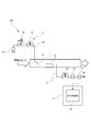
- the schematic diagram which shows the structure of the exhaust gas analyzer which concerns on one Embodiment of this invention.
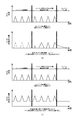
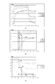
- the graph which shows the result of having verified about the quantity of the injection
- the gas analyzer according to the present embodiment is a so-called exhaust gas analyzer 100, which is used for measuring the concentration of NH 3 contained in exhaust gas discharged from a diesel engine equipped with a urea SCR system.
- a gas pipe 1 through which an exhaust gas as a sample gas flows, a sampling pipe 2 for sampling a part of the exhaust gas from the gas pipe 1, and a measurement point in the sampling pipe 2 A gas measuring mechanism 21 for measuring the concentration of NH 3 contained in the exhaust gas, a gas injection mechanism 3 for injecting a gas having the same component as the measurement target gas having adsorbability into the gas pipe 1, and And a control mechanism 4 for controlling each part.
- the gas pipe 1 and the sampling pipe 2 form a flow path 11 through which exhaust gas flows.
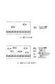
- a region R surrounded by an imaginary line in FIG. 1 indicates an enlarged portion in FIG. 3 to be described later.
- the gas pipe 1 is a generally cylindrical stainless steel pipe attached to an automobile muffler (not shown), and surface processing such as electrolytic polishing so that NOx and soot are less likely to adhere to the inner surface in contact with the exhaust gas. Is given. Further, most of the exhaust gas introduced into the gas pipe 1 is led out from the downstream opening as it is.
- the sampling pipe 2 is a substantially thin cylindrical stainless pipe bent in an L shape, and has one end pierced in the radial direction with respect to the central portion of the gas pipe 1 and the inside of the gas pipe 1. A part of the exhaust gas can be sampled.
- an on-off valve 23, a suction pump 22, and the gas measuring mechanism 21 are provided in order from the upstream.
- the on-off valve is opened and the suction pump 22 sucks the exhaust gas at a predetermined flow rate so as to flow into the sampling pipe 2.
- the inner surface is subjected to surface processing by electrolytic polishing or the like.
- the gas measuring device 21 for example, FTIR (Fourier Transform Infrared Spectroscopy) by contained in the exhaust gas, not only the NH 3, NOx, CO, CO 2, hydrocarbons, simultaneously measurable those concentrations of the various components, such as equal
- the concentration of each component measured at a cycle of 1 second is updated and output. That is, the concentration instruction values of various components contained in the exhaust gas can be updated in substantially real time.
- the measurement point M of the gas measurement mechanism 21 in the present embodiment corresponds to the point where the gas measurement mechanism 21 is provided in the sampling pipe 2.
- the gas injection mechanism 3 is for injecting adsorbing NH 3 among the components to be measured into the gas pipe 1 as an injection gas, one end of which is an injection gas source 31 in which NH 3 is stored. And a gas injection pipe 34 having the other end opened in the gas pipe 1, an on-off valve 33 provided on the gas pipe 1, and a flow rate control valve 32.
- the gas injection mechanism 3 continues to supply a predetermined amount of NH 3 into the gas pipe 1 at least while the concentration of NH 3 in the exhaust gas is measured by the gas measurement mechanism 21.
- the gas injection mechanism 3 is also used when calibration before measurement is performed by introducing NH 3 zero gas and span gas.
- the position where the gas injection pipe 34 opens into the gas pipe 1 will be described in detail.
- the position where the injection gas is introduced is set upstream of the measurement point M of the gas injection mechanism 21. More specifically, one end of the gas injection pipe 34 is located upstream of the location where the sampling pipe 2 is open in the gas pipe 1 and in the vicinity of the opening where the gas pipe 1 is attached to the muffler. Is opened. That is, the NH 3 gas can be dispersed by the gas injection mechanism 3 over substantially the entire area of the flow path 11 from when the exhaust gas is introduced to the measurement point M.
- the area where both NH 3 and the injection gas in the exhaust gas, which is the measurement object gas, contact the inner surface is the area where only NH 3 in the exhaust gas contacts.
- the injection position of the injection gas is set so as to be sufficiently larger than that. For example, even if adsorption occurs on the inner surface where only NH 3 in the exhaust gas contacts, it is set so that only an amount below the measurement limit of the gas measurement mechanism 21 is adsorbed.
- the control mechanism 4 is a so-called computer having an input / output interface, a memory, a CPU, an A / D, a D / A converter, etc., and controls various valves by executing a program stored in the memory. Or, at least the function as the dirt determination unit 41 is exhibited.
- the contamination determination unit 41 is configured to determine the presence or absence of contamination in the flow path 11 based on a value related to the measurement response speed of the adsorptive gas by the gas measurement mechanism 21.
- the gas injection mechanism 3 introduces an adsorptive gas having a known concentration or flow rate into the gas pipe 1 and the sampling pipe 2, and the measurement value output from the gas measurement mechanism 21 at that time.
- dirt such as soot is attached to the inner surface in contact with the flow path 11 through which the exhaust gas as the sample gas flows is acceptable. It is determined that the user is doing.
- the dirt determination unit 41 determines the dirt based on the response time required to stabilize at a predetermined value from a state where nothing is measured as a value related to the measurement response speed, When the response time exceeds a predetermined time, it is determined that the dirt on the inner surface of the gas pipe 1 or the sampling pipe 2 is more than an allowable amount.
- the output value of the gas measurement mechanism 21 is calibrated by the zero gas and the span gas injected by the gas injection mechanism 3. Note that sample gas such as exhaust gas is not introduced into the gas pipe 1 during dirt detection.
- the contamination determination unit 41 injects a span gas in which NH 3 is set to a concentration in the vicinity of the full scale of the gas measurement mechanism 21 into the gas pipe 1, and measures the NH 3 gas measured by the gas measurement mechanism 21.
- the response time t n which is the time taken for the concentration change to stabilize is measured.
- the response time t n when there is dirt is longer than the response time t 0 in the initial state without dirt.
- the surface area increases accordingly, and more adsorbing gas such as NH 3 is adsorbed. Therefore, even if the span gas is injected from the gas injection mechanism 3, the amount of NH 3 gas trapped increases as the contamination increases, and it takes time for the indicated value to reach the concentration set for the span gas. become. That is, the dirt determination unit 41 detects dirt using the fact that the responsiveness of the gas measurement mechanism 21 is deteriorated due to adsorption of adsorbable gas to the dirt.
- the contamination determination unit 41 configured as described above, since the contamination is detected based on the adsorptivity of NH 3 that is an adsorptive gas, it is difficult to detect depending on the flow rate and other parameters, and the adsorptive gas. This makes it possible to immediately detect dirt that has a particularly adverse effect on the measurement of water.
- dirt for example, the gas pipe 1 and the sampling pipe 2 are automatically cleaned up to improve the response speed of the gas measurement mechanism 21 in NH 3 measurement, It is possible to prevent a situation in which an incorrect calibration is performed while adhering to dirt and the measurement is continued with a large error in subsequent measurement.
- the injection gas source 31 is switched to a different one so that NH 3 can be supplied as an injection gas to the gas pipe 1 and the sampling pipe 2 at a concentration different from that of the span gas.
- the concentration of NH 3 as the injection gas is set to be, for example, a value of half or less in the measurable range of the gas measurement mechanism 21, and even if NH 3 derived from exhaust gas is further added, In the gas measurement mechanism 21, the concentration instruction value is not saturated.
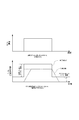
- the gas injection mechanism 3 starts injecting NH 3 as an injection gas into the gas pipe 1 before the exhaust gas flows into the gas pipe 1, that is, before the automobile starts the engine. To do. At this time, the suction pump 22 provided on the sampling pipe 2 has also started to be driven, and the injection gas flows into the sampling pipe 2. Then, as shown in FIG. 3A, the exhaust gas is introduced after the saturation amount that NH 3 is adsorbed on the inner surfaces of the gas pipe 1 and the sampling pipe 2. For example, the exhaust gas may be introduced after a predetermined time has elapsed since the gas injection mechanism 3 started to inject NH 3 , and the gas concentration measured by the gas measurement mechanism 21 is determined by the gas injection mechanism 3. The introduction of exhaust gas may be started when the concentration of the injected gas is substantially stable.
- the predetermined amount which is the amount of the injection gas injected from the gas injection mechanism 3, is adsorbed on the inner surface of the gas pipe 1 of the adsorption gas and the injection gas as shown in FIG.
- the amount of adsorption and the amount of separation of the measurement object gas and the injected gas from the inner surface of the gas pipe 1 are set to be equal to or more than the amount that is substantially balanced.
- the measurement result of the conventional exhaust gas analyzer and the exhaust gas analyzer 100 of the present embodiment are used. A description will be given while comparing the measurement results.
- the actual concentration value is not shown immediately after the engine is started, but the response is caused by the adsorption of NH 3 on the inner surface of the pipe. Delay occurs. After a while, it becomes stable at the actual concentration value, but after the engine is stopped, NH 3 peeled off from the inner surface is detected despite the fact that exhaust gas does not flow in, and the concentration indication value gradually decreases. It will be.
- NH 3 gas is allowed to flow through the gas pipe 1 and the sampling pipe 2 at a constant concentration value as an injection gas before the start of measurement.
- the state is raised by a predetermined density instruction value.
- the concentration indication value output from the gas measuring mechanism 21 can reproduce the actual concentration change derived from the exhaust gas in substantially real time.
- the rise time and fall time in the experimental conditions of (1), (2), and (3) are , 26s, 6s and 2s, respectively. That is, it can be seen that the rise time and the fall time tend to be shorter as the amount of the injected gas is increased and the NH 3 is closer to the saturation amount adsorbed on the inner surface.
- the exhaust gas measured as an exhaust gas analyzer of the present embodiment while continuing to flow the NH 3 from the gas injection mechanism 3, by measuring the NH 3 in the exhaust gas, the response relates NH 3 Measurement of gas measurement mechanism 21 It was proved that the sex could be improved.
- the gas analyzer of the present invention has been described by taking the exhaust gas analyzer as an example, but other gases may be measured as the sample gas.
- NH 3 is taken as an example of the measurement target gas having adsorptivity, but other adsorption gas such as HCl and hydrocarbon (HC) may be used.
- hydrocarbon (HC) include aromatic hydrocarbons such as toluene, alcohols such as metal rule and ethanol, and high boiling point HC.
- examples of the gas having high adsorptivity include those having polarity such as NO 2 , SO 2 , H 2 0 and the like.
- the predetermined amount may be set so that the value relating to the amount of the injected gas indicated by the gas measurement mechanism is equal to or less than a tolerance, in addition to making the predetermined amount an amount that can maintain an equilibrium state for adsorption and separation.
- the tolerance indicates, for example, the amount of error allowed in advance with respect to the full scale that can be measured by a certain measuring instrument, and specifically, a numerical value such as about several percent of the full scale. It is represented by In other words, the measurement range is hardly narrowed by maintaining the equilibrium state so that the concentration indication value derived from the injected gas is within the error of the concentration measurement value allowed by the gas measurement mechanism. In addition, it is possible to know a sufficiently accurate value without performing an operation of subtracting the concentration value derived from the injected gas from the value obtained in order to know the concentration value derived from the exhaust gas.
- the contamination determination unit is configured to detect the presence or absence of contamination based on a response time that is a value related to the measurement response speed of the adsorptive gas. For example, from the measurement value indicated by the gas measurement mechanism, Other related values such as a rate of change when changing to another measurement value may be used. That is, the stain determination unit may make a determination based on a density value measured within a predetermined time.
- the span gas is injected by the gas injection mechanism, and the concentration to be actually measured is stepped, but various measurement values such as a rectangular wave, a sine wave, and a pulse appear. It does not matter.
- a pulse-like change when measured by the gas measurement mechanism, it takes from the time when the adsorptive gas is injected by the gas injection mechanism until it is actually detected by the gas measurement mechanism.
- the presence or absence of dirt may be determined based on the time.
- the place where the adsorptive injection gas is injected by the gas injection mechanism may be anywhere in the flow path through which the sample gas flows and upstream of the measurement point M of the gas measurement mechanism.
- an adsorptive injection gas may be injected.
- the stain determination unit may not only detect the presence / absence of stain but also determine the degree of stain based on the measured value.
- the response time of the non-adsorbing gas is acquired, and the response time of the adsorbing gas and the response time of the non-adsorbing gas are substantially the same, maintenance of the suction pump is necessary or leakage
- the response time of only the adsorptive gas is long, it may be determined that dirt is present in the flow path through which the gas to be measured flows. For example, when dirt is present, the response time of the adsorptive gas deteriorates and becomes longer due to the change in the surface area in the pipe, whereas the non-adsorbing gas is not significantly affected even if the surface area changes. Response time hardly changes.
- the dirt determination unit can strictly determine the cause of two different response delays.
- the gas measuring device is preferably capable of simultaneously measuring multi-component gases, and specific examples of the non-adsorbing gas include CO, CO 2 , NO, N 2 O and the like. .
- the dirt determination unit is not only used in the exhaust gas analyzer, but may be used in other gas analyzers.
- the gas measurement mechanism can measure multi-component gases by FTIR, it may be one that can measure only other adsorptive gases.
- the gas measuring mechanism may be capable of measuring only an adsorptive gas such as NH 3 as in NDIR or laser measurement.
- the value measured by the gas measurement mechanism is not limited to the concentration, and may be a value related to the amount of the adsorptive gas such as the flow rate and the volume.
- the measurement point of the gas measurement mechanism may be provided not in the sampling pipe but in the gas pipe. In short, the injection gas injected from the gas injection mechanism may flow from the upstream of the measurement point together with the gas to be measured.
- the gas measuring mechanism is installed downstream of the suction pump in the embodiment, but may be installed upstream of the suction pump, for example. Even in the case of such a so-called reduced pressure flow, it is possible to obtain the same effects as those described above with respect to contamination detection and measurement of the measurement target gas having adsorptivity.
- the present invention since it is configured to detect the presence or absence of dirt by utilizing the decrease in the response speed caused by the adsorption of the adsorbing injection gas to the inner surface, a small amount of dirt is present. However, it can be accurately detected. Therefore, the flow path can be appropriately cleaned, and the response speed in the measurement of the adsorptive gas that is affected even by a small amount of dirt can be kept good. For these reasons, the present invention can be applied to provide a more accurate exhaust gas analyzer.
Abstract
Description
11 ・・・流路
21 ・・・ガス測定機構
3 ・・・ガス注入機構
本実施形態のガス分析装置は、いわゆる排ガス分析装置100であって、尿素SCRシステムを搭載したディーゼルエンジンから排出される排ガス中に含まれるNH3の濃度を測定するために用いるものである。
Claims (5)
- 試料ガスが流される流路に吸着性の注入ガスを注入するガス注入機構と、
前記流路に流れる吸着性ガスの量に関連する値を測定可能なガス測定機構と、
前記ガス測定機構による前記吸着性ガスの測定応答速度に関連する値に基づいて、前記流路における汚れを判定する汚れ判定部と、を備えたことを特徴とするガス分析装置。 - 前記流路が、前記試料ガスが流されるガス配管内と、前記試料ガスの一部をサンプリングするサンプリング配管内とに形成されており、
前記ガス測定機構が、前記サンプリング配管に設けられているとともに、前記汚れ判定部が、前記測定応答速度に関連する値に基づいて前記サンプリング配管の内表面における汚れを判定するように構成された請求項1記載のガス分析装置。 - 前記ガス注入機構が、前記ガス配管内に吸着性の注入ガスを注入するよう構成された請求項2記載のガス分析装置。
- 前記汚れ判定部が、前記ガス注入機構により吸着性の注入ガスが注入されてから、前記ガス測定機構により所定量以上の吸着性ガスが測定されるまでにかかる測定応答時間が所定時間以上である場合に、前記流路に汚れが有ると判定するように構成された請求項1記載のガス分析装置。
- ガス分析装置において試料ガスが流される流路の汚れ検出方法であって、
前記流路に吸着性の注入ガスを注入するガス注入ステップと、
前記流路に流れる吸着性ガスの量に関連する値を測定するガス測定ステップ
前記ガス測定ステップにおける前記吸着性ガスの測定応答速度に関連する値に基づいて、前記流路における汚れを判定する汚れ判定ステップと、を備えたことを特徴とする汚れ検出方法。
Priority Applications (3)
| Application Number | Priority Date | Filing Date | Title |
|---|---|---|---|
| US14/343,678 US20140202233A1 (en) | 2011-09-08 | 2012-09-03 | Gas analysis device and contamination detection method used in same |
| CN201280042363.0A CN103782160A (zh) | 2011-09-08 | 2012-09-03 | 气体分析装置及其使用的污垢检测方法 |
| EP12829352.9A EP2755012A4 (en) | 2011-09-08 | 2012-09-03 | GAS ANALYSIS DEVICE AND METHOD FOR DETECTING CONTAMINATION USED THEREIN |
Applications Claiming Priority (2)
| Application Number | Priority Date | Filing Date | Title |
|---|---|---|---|
| JP2011-196361 | 2011-09-08 | ||
| JP2011196361 | 2011-09-08 |
Publications (1)
| Publication Number | Publication Date |
|---|---|
| WO2013035675A1 true WO2013035675A1 (ja) | 2013-03-14 |
Family
ID=47832120
Family Applications (1)
| Application Number | Title | Priority Date | Filing Date |
|---|---|---|---|
| PCT/JP2012/072379 WO2013035675A1 (ja) | 2011-09-08 | 2012-09-03 | ガス分析装置及びそれに用いられる汚れ検出方法 |
Country Status (5)
| Country | Link |
|---|---|
| US (1) | US20140202233A1 (ja) |
| EP (1) | EP2755012A4 (ja) |
| JP (1) | JPWO2013035675A1 (ja) |
| CN (1) | CN103782160A (ja) |
| WO (1) | WO2013035675A1 (ja) |
Cited By (1)
| Publication number | Priority date | Publication date | Assignee | Title |
|---|---|---|---|---|
| KR102150880B1 (ko) * | 2019-12-10 | 2020-09-03 | 주식회사 위드텍 | 멀티포트 가스 모니터링 분석기 |
Families Citing this family (4)
| Publication number | Priority date | Publication date | Assignee | Title |
|---|---|---|---|---|
| TWI533921B (zh) * | 2014-03-26 | 2016-05-21 | 財團法人車輛研究測試中心 | 氣體互感現象分析系統及其分析方法 |
| US9606048B2 (en) * | 2014-06-30 | 2017-03-28 | Momentive Performance Materials Inc. | Method for determining the weight and thickness of a passivation or conversion coating on a substrate |
| CN110537019A (zh) * | 2017-02-20 | 2019-12-03 | 西门子歌美飒可再生能源公司 | 用于确定风力涡轮机转子叶片的污染状态的系统和方法 |
| JP7395591B2 (ja) * | 2019-07-25 | 2023-12-11 | 株式会社日立ハイテク | 検体分析装置 |
Citations (6)
| Publication number | Priority date | Publication date | Assignee | Title |
|---|---|---|---|---|
| JPS5773648A (en) * | 1980-10-27 | 1982-05-08 | Mitsubishi Heavy Ind Ltd | Analyzing method for ammonia |
| JPH07333114A (ja) * | 1994-06-08 | 1995-12-22 | Toshiba Corp | 排ガス分析装置 |
| JPH11295293A (ja) * | 1998-04-09 | 1999-10-29 | Ishikawajima Harima Heavy Ind Co Ltd | 排ガス中の無水硫酸測定方法及び装置及び無水硫酸中和装置 |
| JP2002310910A (ja) | 2001-04-09 | 2002-10-23 | Nippon Soken Inc | ガス濃度計測装置 |
| JP2003014634A (ja) * | 2001-06-28 | 2003-01-15 | Ishikawajima Harima Heavy Ind Co Ltd | So3,nh3同時連続濃度計 |
| JP2010060557A (ja) * | 2008-08-14 | 2010-03-18 | Breen Energy Solutions | 煙道ガス中の三酸化硫黄および他の凝縮性物質の検出、測定および制御のための方法および装置 |
Family Cites Families (10)
| Publication number | Priority date | Publication date | Assignee | Title |
|---|---|---|---|---|
| JPS60123759A (ja) * | 1983-12-07 | 1985-07-02 | Fuji Electric Co Ltd | 酸素ガスセンサの汚損検出方法 |
| WO2000042415A1 (en) * | 1999-01-12 | 2000-07-20 | Envirotest Systems Corp. | Remote vehicle emission sensing device with single detector |
| US6996975B2 (en) * | 2004-06-25 | 2006-02-14 | Eaton Corporation | Multistage reductant injection strategy for slipless, high efficiency selective catalytic reduction |
| DE102005031552B4 (de) * | 2005-07-06 | 2023-10-12 | Abb Ag | Verfahren zur Betriebsprüfung einer Messeinrichtung |
| DE102005062120B4 (de) * | 2005-12-23 | 2016-06-09 | Robert Bosch Gmbh | Verfahren und Vorrichtung zur Überwachung eines Abgasnachbehandlungssystems |
| JP4888171B2 (ja) * | 2006-07-27 | 2012-02-29 | 株式会社デンソー | 排気浄化装置 |
| KR100974599B1 (ko) * | 2008-08-07 | 2010-08-06 | 현대자동차주식회사 | 차량의 요소 분사량 제어장치 및 방법 |
| US8091416B2 (en) * | 2009-01-16 | 2012-01-10 | GM Global Technology Operations LLC | Robust design of diagnostic enabling conditions for SCR NOx conversion efficiency monitor |
| US8375700B2 (en) * | 2010-03-30 | 2013-02-19 | Detroit Diesel Corporation | Apparatus and method for monitoring oxidation catalyst functionality |
| US8800274B2 (en) * | 2011-05-12 | 2014-08-12 | GM Global Technology Operations LLC | Method for managing ammonia slip |
-
2012
- 2012-09-03 US US14/343,678 patent/US20140202233A1/en not_active Abandoned
- 2012-09-03 CN CN201280042363.0A patent/CN103782160A/zh active Pending
- 2012-09-03 WO PCT/JP2012/072379 patent/WO2013035675A1/ja active Application Filing
- 2012-09-03 EP EP12829352.9A patent/EP2755012A4/en not_active Withdrawn
- 2012-09-03 JP JP2013532587A patent/JPWO2013035675A1/ja not_active Withdrawn
Patent Citations (6)
| Publication number | Priority date | Publication date | Assignee | Title |
|---|---|---|---|---|
| JPS5773648A (en) * | 1980-10-27 | 1982-05-08 | Mitsubishi Heavy Ind Ltd | Analyzing method for ammonia |
| JPH07333114A (ja) * | 1994-06-08 | 1995-12-22 | Toshiba Corp | 排ガス分析装置 |
| JPH11295293A (ja) * | 1998-04-09 | 1999-10-29 | Ishikawajima Harima Heavy Ind Co Ltd | 排ガス中の無水硫酸測定方法及び装置及び無水硫酸中和装置 |
| JP2002310910A (ja) | 2001-04-09 | 2002-10-23 | Nippon Soken Inc | ガス濃度計測装置 |
| JP2003014634A (ja) * | 2001-06-28 | 2003-01-15 | Ishikawajima Harima Heavy Ind Co Ltd | So3,nh3同時連続濃度計 |
| JP2010060557A (ja) * | 2008-08-14 | 2010-03-18 | Breen Energy Solutions | 煙道ガス中の三酸化硫黄および他の凝縮性物質の検出、測定および制御のための方法および装置 |
Non-Patent Citations (1)
| Title |
|---|
| See also references of EP2755012A4 |
Cited By (1)
| Publication number | Priority date | Publication date | Assignee | Title |
|---|---|---|---|---|
| KR102150880B1 (ko) * | 2019-12-10 | 2020-09-03 | 주식회사 위드텍 | 멀티포트 가스 모니터링 분석기 |
Also Published As
| Publication number | Publication date |
|---|---|
| JPWO2013035675A1 (ja) | 2015-03-23 |
| US20140202233A1 (en) | 2014-07-24 |
| CN103782160A (zh) | 2014-05-07 |
| EP2755012A1 (en) | 2014-07-16 |
| EP2755012A4 (en) | 2015-04-22 |
Similar Documents
| Publication | Publication Date | Title |
|---|---|---|
| RU2721669C2 (ru) | Способ (варианты) и система для выполнения самодиагностической проверки датчика оксидов азота | |
| WO2013035675A1 (ja) | ガス分析装置及びそれに用いられる汚れ検出方法 | |
| US10883410B2 (en) | Systems and methods for performing a NOx self-diagnostic test | |
| US8694197B2 (en) | Gain/amplitude diagnostics of NOx sensors | |
| CN102590445B (zh) | 排气分析系统和排气分析方法 | |
| US8930121B2 (en) | Offset and slow response diagnostic methods for NOx sensors in vehicle exhaust treatment applications | |
| JP6313146B2 (ja) | パティキュレートフィルタの故障診断方法及び装置 | |
| TW201829903A (zh) | 內燃機及控制內燃機之方法 | |
| JP4267535B2 (ja) | 排気浄化装置のNOx低減率測定方法 | |
| US8745968B2 (en) | Abnormality detection apparatus for particulate filter | |
| JP5395318B2 (ja) | 内燃機関の運転方法および装置 | |
| Kato et al. | Thick film ZrO2 NOx sensor for the measurement of low NOx concentration | |
| RU2667863C1 (ru) | Выявление и количественное определение утечек аммиака после системы избирательного каталитического восстановления оксидов азота | |
| JP7169339B2 (ja) | 排気ガスの気体種の濃度を光学的に測定する方法及びシステム | |
| GB2503446A (en) | Method and apparatus for selective catalytic reduction device slip detection | |
| US9068495B2 (en) | Oxidation catalyst/hydrocarbon injector testing system | |
| CN110594019B (zh) | 一种检测发动机排气漏气的方法及装置 | |
| WO2013035657A1 (ja) | 吸着性ガス分析装置及び吸着性ガス分析方法 | |
| JP2011242194A (ja) | 排ガス測定装置および排ガス採取方法 | |
| JP2010139281A (ja) | 排気ガス測定装置 | |
| JP2019086492A (ja) | 排ガス分析装置 | |
| Hoard et al. | NH 3 storage in sample lines | |
| Sutjiono et al. | Real-time on-board indirect light-off temperature estimation as a detection technique of diesel oxidation catalyst effectiveness level | |
| Lamas et al. | Optimization of Automotive Exhaust Sampling Parameters for Evaluation of After-Treatment Systems Using FTIR Exhaust Gas Analyzers | |
| JP3129840U (ja) | 揮発性有機化合物測定装置 |
Legal Events
| Date | Code | Title | Description |
|---|---|---|---|
| 121 | Ep: the epo has been informed by wipo that ep was designated in this application |
Ref document number: 12829352 Country of ref document: EP Kind code of ref document: A1 |
|
| ENP | Entry into the national phase |
Ref document number: 2013532587 Country of ref document: JP Kind code of ref document: A |
|
| WWE | Wipo information: entry into national phase |
Ref document number: 14343678 Country of ref document: US |
|
| NENP | Non-entry into the national phase |
Ref country code: DE |
|
| WWE | Wipo information: entry into national phase |
Ref document number: 2012829352 Country of ref document: EP |