WO2013035403A1 - 粒子検出装置 - Google Patents
粒子検出装置 Download PDFInfo
- Publication number
- WO2013035403A1 WO2013035403A1 PCT/JP2012/065347 JP2012065347W WO2013035403A1 WO 2013035403 A1 WO2013035403 A1 WO 2013035403A1 JP 2012065347 W JP2012065347 W JP 2012065347W WO 2013035403 A1 WO2013035403 A1 WO 2013035403A1
- Authority
- WO
- WIPO (PCT)
- Prior art keywords
- collection
- unit
- particles
- fluorescence
- heating
- Prior art date
- Legal status (The legal status is an assumption and is not a legal conclusion. Google has not performed a legal analysis and makes no representation as to the accuracy of the status listed.)
- Ceased
Links
Images











Classifications
-
- G—PHYSICS
- G01—MEASURING; TESTING
- G01N—INVESTIGATING OR ANALYSING MATERIALS BY DETERMINING THEIR CHEMICAL OR PHYSICAL PROPERTIES
- G01N15/00—Investigating characteristics of particles; Investigating permeability, pore-volume or surface-area of porous materials
- G01N15/06—Investigating concentration of particle suspensions
- G01N15/0606—Investigating concentration of particle suspensions by collecting particles on a support
-
- G—PHYSICS
- G01—MEASURING; TESTING
- G01N—INVESTIGATING OR ANALYSING MATERIALS BY DETERMINING THEIR CHEMICAL OR PHYSICAL PROPERTIES
- G01N15/00—Investigating characteristics of particles; Investigating permeability, pore-volume or surface-area of porous materials
- G01N15/06—Investigating concentration of particle suspensions
- G01N15/075—Investigating concentration of particle suspensions by optical means
Definitions
- the present invention relates to a particle detection device, and more particularly to a particle detection device that detects biologically derived particles.
- Patent Document 1 Japanese Patent Application Laid-Open No. 2006-081427 is a prior document disclosing a bacteria counting apparatus for detecting bacteria from a change in fluorescence emission intensity.
- a microorganism collection filter is placed on an observation fixing table of an inspection table and fixed with a filter press. In this state, the examination table is moved in the horizontal direction, and the microorganism collection filter is moved between the lower part of the ultraviolet irradiation part and the lower part of the light receiving part.
- Collecting member such as a filter for collecting microorganisms is exchanged for each detection. Therefore, the structure which can replace
- the present invention has been made in view of the above problems, and an object of the present invention is to provide a particle detection device in which a collecting member can be easily replaced.
- the particle detection device is a particle detection device that detects biologically derived particles.
- the particle detection apparatus includes a first member having an introduction port, a housing having a discharge port facing the introduction port, the second member being combined with the first member and having a box shape, and the housing from the discharge port. And an exhaust part for exhausting the air.
- the particle detection device is located in the casing, and discharges the particles contained in the air introduced into the casing from the introduction port by exhaust of the exhaust section; And a collecting part that collects by adhering to the collecting member.
- the particle detection device includes an irradiation unit that irradiates the excitation light toward the particles attached to the collection member and located in the enclosure, and fluorescence emitted from the particles that are located in the enclosure and irradiated with the excitation light.
- the particle detector is configured such that the difference between the amount of fluorescence detected from particles irradiated with excitation light before heating by the heating unit and the amount of fluorescence detected from particles irradiated again with excitation light after heating by the heating unit.
- a moving mechanism that moves the collection member.
- the moving mechanism positions the collection member at the first position when the charged particles are attached to the collection member while charging the particles by the discharge unit, and the irradiation unit irradiates the particles attached to the collection member with the excitation light.
- the fluorescence is detected by the fluorescence detection unit
- the collection member is positioned at a second position different from the first position.
- the discharge part, the irradiation part, and the fluorescence detection part are attached to the first member.
- the collection part and the heating part are attached to the second member.
- the first member and the second member are detachably combined.
- the moving mechanism is attached to the first member.
- the moving mechanism includes a rotation driving unit and an engagement unit that transmits a driving force of the rotation driving unit.
- the collecting part has an engaged part engaged with the engaging part, and a collecting member at a position separated in the radial direction with the engaged part as a rotation center. The collecting member is rotated by driving the rotation driving unit and moves between the first position and the second position.
- the particle detection device includes a biasing member that is interposed between the engaging portion and the engaged portion and biases the engaging portion and the engaged portion away from each other. Further prepare.
- the biasing member has elasticity and attaches the collection portion toward the second member by the elastic force in a state where the first member and the second member are combined and elastically deformed. To force.
- the second member has a female screw portion for attaching the collecting portion.
- the collection part has a shaft part to be attached to the second member at a position facing the engaged part, and a bearing member having a male screw part screwed to the female screw part on the outer surface. By supporting the shaft portion, the distance from the second member is adjusted.
- the collecting member can be easily replaced.
- the biological particles are particles derived from organisms including microorganisms and fungi such as molds and pollen, and do not include dusts such as minerals and refined petroleum products.
- the particles floating in the air are mixed with dusts such as minerals and refined petroleum products and biological particles.
- dusts such as minerals and refined petroleum products and biological particles.
- the mixed particles include chemical fiber dust that emits fluorescence (hereinafter also referred to as dust) in addition to biologically derived particles. Therefore, the amount of biologically derived particles cannot be measured only by detecting the fluorescence emitted from the mixed particles.
- the present inventors utilize the fact that the fluorescence intensity (fluorescence amount) changes when the biological particles are heated, and that the fluorescence intensity does not change even when dust such as chemical fibers is heated.
- a particle detection method was developed to measure the amount of particles.
- FIG. 1 is a graph showing fluorescence intensity of biological particles before and after heating.
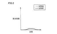
- FIG. 2 is a graph showing the fluorescence intensity of the dust before and after heating. 1 and 2, the vertical axis represents the fluorescence intensity, and the horizontal axis represents the wavelength of the fluorescent light.
- the amount of fluorescence after heating is remarkably increased in comparison with the amount of fluorescence before heating in a wide wavelength range.
- the amount of fluorescence after heating is substantially the same as the amount of fluorescence before heating.
- the biological particles contained in the mixed particles The amount of can be calculated.
- the particle detection method includes a step of collecting mixed particles, a step of measuring mixed particles before heating, a step of heating mixed particles, a step of measuring mixed particles after heating, and a step of calculating the amount of biological particles. including.
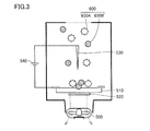
- FIG. 3 is a schematic diagram for explaining the collection process.
- FIG. 4 is a schematic diagram for explaining the fluorescence measurement process before heating.
- FIG. 5 is a schematic diagram for explaining the heating step.
- FIG. 6 is a schematic diagram for explaining the fluorescence measurement process after heating.
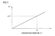
- FIG. 7 is a graph showing the correlation between the amount of increase in fluorescence due to heating and the concentration of biological particles. In FIG. 7, the vertical axis indicates the amount of increase in fluorescence due to heating, and the horizontal axis indicates the concentration of biological particles.
- the mixed particles floating in the air are collected on a collection substrate 510.
- the collection substrate 510 is disposed to face the electrostatic needle 530.
- a DC power source 540 is connected to the collection substrate 510 and the electrostatic needle 530, and a potential difference is generated between the collection substrate 510 and the electrostatic needle 530.
- the positive electrode of the DC power source 540 is connected to the electrostatic needle 530
- the negative electrode of the DC power source 540 is connected to the collection substrate 510.
- the mixed particles 600 floating in the air are charged with a positive charge around the electrostatic needle 530.
- the collection substrate 510 has a charge opposite to that of the charged mixed particles 600. Therefore, the charged mixed particles 600 are collected by adhering to the surface of the collection substrate 510 by electrostatic force.
- the mixed particles 600 collected on the collection substrate 510 include biological particles 600A and dust 600B such as chemical fiber dust.
- excitation light is irradiated from the light emitting element 550 such as a semiconductor laser toward the mixed particles 600 collected on the collection substrate 510.
- the fluorescence emitted from the mixed particles 600 irradiated with the excitation light is condensed by the lens 560 and received by the light receiving element 565.
- the mixed particles 600 collected on the collection substrate 510 are heated by heating the collection substrate 510 with a heater 520 attached to the lower surface of the collection substrate 510. After heating, the collection substrate 510 is air-cooled.
- excitation light is irradiated from the light emitting element 550 toward the mixed particles 600 collected on the collection substrate 510.
- the fluorescence emitted from the mixed particles 600 irradiated with the excitation light is condensed by the lens 560 and received by the light receiving element 565.
- the fluorescence measured in the fluorescence measurement step before heating from the fluorescence amount measured in the fluorescence measurement step after heating.
- the concentration N1 particles / m 3
- the correlation between the increase ⁇ F and the biological particle concentration N is obtained by conducting an experiment in advance.
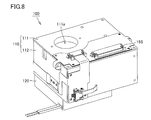
- FIG. 8 is a perspective view showing an appearance of the particle detection apparatus according to the embodiment of the present invention.
- FIG. 9 is a perspective view of the particle detector of FIG. 8 as seen from another direction.
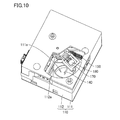
- FIG. 10 is a perspective view showing a state where the fan is removed from the particle detection apparatus of FIG.
- FIG. 11 is an exploded perspective view showing the configuration of the particle detection apparatus of FIG.
- the particle detection device 100 in the present embodiment includes a housing 110, an exhaust unit, a discharge unit, a collection unit, an irradiation unit 130, a fluorescence detection unit 160, and a heating unit. , A calculation unit 186, a moving mechanism, and a cleaning unit.
- the casing 110 has a lid portion 111 that is a first member having an introduction port 111a, and a discharge port 112a that faces the introduction port 111a, and a main body that is a second member that is combined with the lid portion 111 to form a box shape. Part 112 is included.
- the housing 110 has a substantially rectangular parallelepiped shape, and houses a discharge part, a collection part, an irradiation part, a fluorescence detection part, a heating part, a moving mechanism, and a cleaning part.
- the main body 112 has an opening on the side opposite to the discharge port 112a.
- the lid portion 111 has a flat plate shape that closes the opening of the main body portion 112.
- the housing 110 has a size of 60 mm ⁇ 50 mm (length and width of the lid portion 111) ⁇ 30 mm (height).
- the collection tube 190 is connected to the lid portion 111 so as to be orthogonal to each other.
- the collection tube 190 extends in a cylindrical shape toward the main body 112 so as to be continuous with the introduction port 111a.
- the collection tube 190 is provided so as to surround an electrostatic needle 140 described later.
- the collection tube 190 guides air containing mixed particles toward the collection substrate 170 positioned facing the electrostatic needle 140.
- the fan 120 serving as an exhaust unit exhausts the air in the housing 110 from the exhaust port 112a.
- the fan 120 can be driven to rotate in the forward direction and the reverse direction. By driving the fan 120 in the forward rotation direction, the air inside the casing 110 is discharged to the outside of the casing 110 through the fan 120. By driving the fan 120 in the reverse direction, air outside the casing 110 is introduced into the casing 110 through the fan 120.
- the fan 120 is attached to the position of the discharge port 112a of the main body 112.
- the discharge part is located in the casing 110 and charges the mixed particles contained in the air introduced into the casing 110 from the inlet 111a by the exhaust of the fan 120.
- the discharge unit includes a high-voltage DC power supply 141 as a power supply unit and an electrostatic needle 140 as a discharge electrode.
- the electrostatic needle 140 extends from the high-voltage DC power supply 141, passes through the collection tube 190, and reaches the inside of the collection tube 190.
- the tip of the electrostatic needle 140 extends in the axial direction of the collection tube 190.
- the positive electrode of the high-voltage DC power supply 141 is connected to the electrostatic needle 140, and the negative electrode is connected to the collection substrate 170 by wiring not shown.
- the negative electrode of the high-voltage DC power supply 141 may be connected to the electrostatic needle 140 and the positive electrode may be connected to the collection substrate 170. Further, the collection substrate 170 may be fixed to the ground potential. Due to the high-voltage DC power supply 141, a potential difference is generated between the collection substrate 170 and the electrostatic needle 140.
- the collection unit has a collection substrate 170 that is a collection member, and collects the charged mixed particles by attaching them to the collection substrate 170 by electrostatic force.
- the collection substrate 170 is formed from a glass plate.
- a conductive transparent film is formed on the surface of the glass plate.
- the collection substrate 170 is not limited to glass, and may be formed of ceramic or metal.
- a film is not limited to a transparent film, For example, a metal film may be formed.
- substrate 170 is formed from a metal, it is not necessary to form a film on the surface.
- the collection substrate 170 is fixed on the substrate holder 171.
- the substrate holder 171 is connected to a rotation base 172 connected to a moving mechanism described later.
- An arm portion 176 bulges from the rotation base 172.
- the substrate holder 171, the rotation base 172, and the arm portion 176 are integrally formed of a resin material.
- the collection unit includes a substrate holder 171, a rotation base 172, and an arm unit 176.
- the irradiation unit 130 is located in the housing 110 and irradiates excitation light toward the mixed particles attached to the collection substrate 170.
- the irradiation unit 130 includes a light emitting element 131 as a light source, an element frame 132, a lens frame 133, a condenser lens 134, and a lens holder 135.
- the light emitting element 131 a semiconductor laser or an LED (Light Emitting Diode) element is used.
- the light emitted from the light emitting element 131 may have a wavelength in either the ultraviolet or visible region as long as it excites biological particles to emit fluorescence.
- the fluorescence detection unit 160 is located in the casing 110 and detects fluorescence emitted from the mixed particles irradiated with excitation light.
- the fluorescence detection unit 160 includes a noise shield 161, an amplifier circuit 162, a light receiving element 163, a light receiving frame 164, a Fresnel lens 165, and a lens presser 166.
- the heater 180 serving as a heating unit is located in the casing 110 and heats mixed particles adhering to the collection substrate 170.
- the heater 180 is attached to the lower surface of the collection substrate 170.
- the heater 180 includes a power supply line to the heater 180 and a signal line of a temperature sensor built in the heater 180. The power supply line and the signal line are drawn out of the casing 110 through a flexible substrate (not shown) connected to the rotation base 172.
- the moving mechanism moves the collection substrate 170.
- the moving mechanism includes a motor holder 175, a rotation motor 174 as a rotation drive unit, and a motor presser 173.
- the rotation motor 174 is connected to the rotation base 172 of the collection unit.
- the cleaning unit removes the mixed particles after the fluorescence detection from the collection substrate 170.
- the cleaning unit includes a brush 150, a brush press 151, and a brush fixing unit 152.
- the brush 150 is sandwiched between a brush press 151 and a brush fixing portion 152 and fixed at one end.
- the cleaning unit is fixed to the lower surface of the high-voltage DC power supply 141.
- the brush 150 is formed from a conductive fiber assembly.
- the brush 150 is made of, for example, carbon fiber.
- the fiber aggregate forming the brush 150 preferably has a diameter of ⁇ 0.05 mm or more and ⁇ 0.2 mm or less.
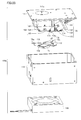
- FIG. 12 is an exploded perspective view showing an attachment state of each component of the particle detection device.
- FIG. 13 is a view of the particle detection device of FIG. 12 as viewed from the direction of arrow XIII.
- FIG. 14 is a perspective view showing a state in which the collecting portion is attached to the main body portion.
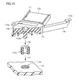
- FIG. 15 is an exploded perspective view showing an enlarged attachment structure of the collection part and the main body part.
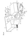
- FIG. 16 is a perspective view illustrating a state in which the collection unit is attached to the main body unit.
- FIG. 17 is a partial cross-sectional perspective view showing a state in which the bearing member is fitted to the shaft portion of the collecting portion.
- FIG. 18 is a cross-sectional view illustrating a state in which the interval between the collection portion and the main body portion is adjusted by the bearing member.
- the discharge unit, the irradiation unit 130, the fluorescence detection unit 160, and the cleaning unit are attached to the lid unit 111.
- the moving mechanism is also attached to the lid 111.
- the moving mechanism may be attached to the main body 112.
- the collection unit is attached to the main body unit 112. Since the heater 180 that is a heating unit is attached to the lower surface of the collection substrate 170, the heater 180 is attached to the main body 112 together with the collection unit.
- the collection part has an engagement hole 172a, which is an engaged part engaged with the output shaft 174a of the rotation motor 174, in the rotation base 172. Moreover, the collection part has the collection board
- the main body portion 112 has a female screw portion 112d for attaching the collecting portion at the bottom.
- the rotation base 172 of the collection part has a shaft part 172b to be attached to the main body part 112 at a position facing the engagement hole 172a.
- the central axis of the engagement hole 172a and the central axis of the shaft portion 172b substantially coincide with each other.
- the bearing member 177 has a male screw portion 177a that is screwed with the female screw portion 112d on the outer surface.
- the shaft portion 172 b is supported by the main body portion 112 via the bearing member 177.
- the shaft portion 172b is rotatably supported with respect to the bearing member 177.
- the collection part is made rotatable in a plane parallel to the bottom part of the main body part 112 with the shaft part 172b as the rotation center axis.
- the collection portion and the bottom portion of the main body portion 112 are adjusted.
- the interval between can be adjusted.
- the position of the engagement hole 172a can be adjusted up and down.
- the arm portion 176 extends in the radial direction with the engagement hole 172a of the rotation base 172 as the rotation center.
- the arm portion 176 is provided at a position shifted in the circumferential direction from the substrate holder 171 around the axis of the shaft portion 172b.
- the arm portion 176 has a thin arm tip 176a at the tip.
- the proximity sensor 112b and the proximity sensor 112c are arranged on inner walls that are orthogonally adjacent to each other.
- the proximity sensor 112b and the proximity sensor 112c are provided in the same plane orthogonal to the central axis of the female screw portion 112d.
- Each of the proximity sensor 112 b and the proximity sensor 112 c has a pair of terminal portions extending from the inner wall of the main body portion 112 toward the inside of the main body portion 112.
- the collection part is attached to the main body part 112 so that the arm tip part 176a passes between the pair of terminal parts when the shaft part 172b is rotated about the rotation center axis.
- the proximity sensor 112b and the proximity sensor 112c are sensors that detect the position of the collection substrate 170 by detecting the proximity of the arm tip 176a.
- the collecting part and the moving mechanism are connected.
- the lid portion 111 and the main body portion 112 are detachably combined.
- the lid portion 111 and the main body portion 112 are detachably combined with a fastening member or a biasing member to constitute the casing 110.
- FIG. 19 is a perspective view showing a state where the collection unit and the moving mechanism are connected.
- the casing 110 is not shown.
- the collection part and the moving mechanism are connected.
- the rotation base 172 rotates (forward rotation, reverse rotation) about the engagement hole 172a.
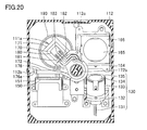
- FIG. 20 is a cross-sectional view of the state where the collection substrate is located at the first position, as viewed from below the collection substrate.
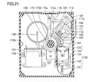
- FIG. 21 is a cross-sectional view of the state where the collection substrate is located at the second position, as viewed from below the collection substrate.
- FIG. 22 is a cross-sectional view of the state where the collection substrate is located at the third position, as viewed from below the collection substrate.
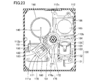
- FIG. 23 is a cross-sectional view of the state where the collection substrate is located at the fourth position, as viewed from below the collection substrate.
- the discharge part, the fluorescence detection part, and the cleaning part are arranged side by side in the circumferential direction around the shaft part 172b of the rotation base 172.
- a fluorescence detection unit, a discharge unit, and a cleaning unit are arranged in order counterclockwise.
- the irradiation unit 130 is disposed adjacent to the fluorescence detection unit.
- the first position is the position of the collection substrate 170 when the charged particles are attached to the collection substrate 170 while charging the mixed particles by the discharge unit.
- the second position is the position of the collection substrate 170 when the fluorescence is detected by the fluorescence detection unit while irradiating excitation light to the mixed particles attached to the collection substrate 170 by the irradiation unit 130.
- the third position is the position of the collection substrate 170 when the cleaning unit starts removing the mixed particles on the collection substrate 170.
- the fourth position is the position of the collection substrate 170 when the removal of the mixed particles on the collection substrate 170 by the cleaning unit is completed.
- a turning range around the shaft portion 172b from the first position to the fourth position is within about 180 °.
- the collection substrate 170 is rotated by driving the rotation motor 174 to move between the first position and the second position. Further, the collection substrate 170 is rotated by driving the rotation motor 174 and moves between the second position and the third position. Further, the collection substrate 170 is rotated by driving the rotation motor 174 to move between the third position and the fourth position.
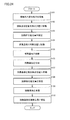
- FIG. 24 is a flowchart showing an operation flow of the particle detection apparatus according to the present embodiment.
- clockwise rotation around the shaft portion 172b is referred to as normal rotation direction
- counterclockwise rotation is referred to as reverse direction.
- the collection substrate 170 is arranged at the first position which is the collection position.
- the fan 120 is driven in the forward rotation direction to introduce air into the housing 110 from the introduction port 111a, and between the electrostatic needle 140 and the collection substrate 170 by the high-voltage DC power supply 141. A potential difference is generated between them, and the mixed particles floating in the air are charged and attached to the surface of the collection substrate 170 for collection (S101).
- the needle-shaped electrostatic needle 140 is used as the discharge electrode, the charged mixed particles are irradiated on the surface of the collection substrate 170 facing the electrostatic needle 140 and irradiated by the irradiation unit 130. It can be attached to a very narrow area corresponding to the area. Thereby, in the fluorescence measurement process of a post process, the fluorescence emitted from the collected mixed particles can be detected efficiently.
- the rotation motor 174 is driven to rotate the rotation base 172 in the normal rotation direction, and the collection substrate 170 is moved to the second position which is the fluorescence detection position (S102).
- the irradiation unit 130 irradiates the excitation light toward the mixed particles that are attached to the collection substrate 170 and collected, and the fluorescence detection unit irradiates the excitation light. Fluorescence emitted from the mixed particles is received. Thereby, the amount of fluorescence before heating of the mixed particles collected by being attached to the collection substrate 170 is measured (S103).
- the rotation motor 174 is driven to rotate the rotation base 172 in the reverse direction, and the collection substrate 170 is moved from the second position to the first position (S104).
- the mixed particles collected by adhering to the collection substrate 170 are heated by energizing the heater 180 and heating the collection substrate 170 (S105).
- the rotation motor 174 is driven to rotate the rotation base 172 in the normal rotation direction, and the collection substrate 170 is moved from the first position to the second position (S107).
- the irradiation unit 130 irradiates excitation light toward the mixed particles that are attached to the collection substrate 170 and collected, and the fluorescence detection unit irradiates excitation light. Fluorescence emitted from the mixed particles is received. Thereby, the amount of fluorescence after heating of the mixed particles collected by being attached to the collection substrate 170 is measured (S108).
- the rotation motor 174 is driven to rotate the rotation base 172 in the reverse direction, and the collection substrate 170 is moved from the second position to the third position. Further, the collection base 170 is moved from the third position to the fourth position by rotating the rotation base 172 in the reverse direction. While the collection substrate 170 moves from the third position to the fourth position, the surface of the collection substrate 170 slides with the tip of the brush 150. Thereby, the mixed particles are removed from the collection substrate 170 (S109).
- the fan 120 is driven in the normal direction to discharge the mixed particles removed from the collection substrate 170 to the outside of the housing 110 from the discharge port 112a.
- a range in which the collection substrate 170 and the collection cylinder 190 overlap with each other decreases, and thus the opening area of the collection cylinder 190 increases.
- mixed particles can be efficiently discharged to the outside of the casing 110.
- the opening area of the collection cylinder 190 is reduced by being shielded by the collection substrate 170 during the collection process, it is possible to reduce air introduction loss.
- the cleaning process is performed by moving the collection substrate 170 while the cleaning unit is stationary, it is not necessary to separately provide a moving mechanism for the cleaning unit. For this reason, size reduction and cost reduction of the particle
- the rotation motor 174 is driven to rotate the rotation base 172 in the forward rotation direction, and the collection substrate 170 is moved from the fourth position to the first position (S110).
- the detection of the particles derived from living organisms is performed by the calculation unit 186 such as a CPU (Central Processing Unit) connected to the fluorescence detection unit and the fluorescence amount measured in the fluorescence measurement step before heating and the fluorescence measurement step after heating. This is done by calculating the amount of bio-derived particles contained in the mixed particles from the difference from the measured fluorescence amount.
- the calculation unit 186 may be attached to the lid 111 inside or outside the housing 110, or may be disposed outside the housing 110.
- the adhesion of the mixed particles to the collection substrate 170 and the removal of the mixed particles from the collection substrate 170 are repeatedly performed as described above. It may be necessary to replace the collection substrate 170.
- the particle detection apparatus 100 is attached with the main body 112 to which the collection unit including the collection substrate 170 is attached, and other main components (discharge unit, irradiation unit 130, fluorescence detection unit 160, moving mechanism).
- the formed lid portion 111 is detachably combined.
- the lid portion 111 and the main body portion 112 are removed, and the main body portion to which the removed lid portion 111 and the collection portion including the new collection substrate 170 are attached.
- the collection substrate 170 can be easily replaced. That is, the main body part 112 to which the collecting part is attached can be configured as a replacement unit.
- the lid portion 111 and the main body portion 112 are combined, the lid portion 111 and the main body portion 112 are engaged by engaging the engagement hole 172a of the rotation base 172 of the collection portion with the output shaft 174a of the rotary motor 174. Therefore, the position of the collection substrate 170 in the housing 110 can be stabilized. As a result, it is possible to suppress variations in detection accuracy of biologically derived particles.
- the position of the engagement hole 172a can be adjusted up and down by adjusting the screwing length between the male screw part 177a of the bearing member 177 and the female screw part 112d of the main body part 112. Therefore, even when the position of the output shaft 174a is shifted in the vertical direction due to stacking of parts crossing and assembly tolerances of the moving mechanism attached to the lid 111, the position of the engagement hole 172a is adjusted by adjusting the position of the engagement hole 172a.
- the hole 172a and the output shaft 174a can be engaged with each other.
- the collection position (first position), the fluorescence detection position (second position), and the cleaning position (third to fourth positions) are arranged side by side on the circumference, and the collection substrate 170 is By rotating in the forward rotation direction and the reverse rotation direction, these positions are moved.
- the particle detector 100 can be downsized.
- the heating step of heating the mixed particles collected on the collection substrate 170 is the same position (first position) as the collection step of collecting the particles on the collection substrate 170 and collecting them. By implementing in, it can attain size reduction of the particle
- the engaging portion of the rotary motor 174 is configured by the output shaft 174a and the engaged portion of the rotating base 172 is configured by the engaging hole 172a. You may comprise the to-be-engaged part of the rotation base 172 with an input shaft.
- FIG. 25 is an exploded perspective view showing an attachment state of each component of the particle detection device according to the modification of the present embodiment.
- FIG. 26 is an exploded perspective view showing the assembling relationship of the urging member in the modification of the present embodiment.
- FIG. 27 is a partial cross-sectional view schematically showing the urging force by the urging member in a state where the lid portion and the main body portion are assembled in the modification of the present embodiment.
- the particle detection device 100a according to the present modification is different from the particle detection device 100 according to the above-described embodiment only in that the bias detection member 178 is provided, and thus the description of other configurations will not be repeated.
- the particle detector 100a As shown in FIGS. 25 and 26, the particle detector 100a according to the present modification is interposed between the output shaft 174a of the rotation motor 174 and the engagement hole 172a of the rotation base 172, and engages with the output shaft 174a.
- a biasing member 178 that biases the holes 172a away from each other is provided.
- a spring such as a leaf spring or a helical spring, or an elastic member such as foaming resin or rubber can be used.
- a high-functional urethane foam such as a microcell polymer sheet (PORON (registered trademark) manufactured by Roger Sinoac Co., Ltd.) can be used.
- the urging member 178 has elasticity, and the rotation base 172 of the collection part is moved to the main body by the elastic force in a state where the cover part 111 and the main body part 112 are elastically deformed. It urges toward the part 112.
- the output shaft 174a and the engagement hole 172a are engaged, and the biasing force interposed between the output shaft 174a and the engagement hole 172a.
- the member 178 is elastically deformed so as to be compressed. As a result, an urging force composed of an elastic force is generated in the direction indicated by the arrow 40.
- the main body 112 has a protruding portion 112e for attaching the collecting portion at the bottom.
- a bearing portion 112f is formed inside the protruding portion 112e.
- the protrusion 112e supports the rotation base 172 in a rotatable manner.
- the rotation base 172 With the shaft portion 172b of the rotation base 172 inserted through the bearing portion 112f of the main body portion 112, the rotation base 172 is urged by the urging member 178, so that the step portion 172c and the protrusion 112e of the rotation base 172 are urged. It is positioned in contact with the upper end surface 112g. Thus, by using the biasing member 178, the rotation base 172 can be positioned in the height direction with respect to the main body 112.
- the engagement hole 172a is interposed via the biasing member 178. And the output shaft 174a can be engaged with each other.
- the biasing member 178 is elastically deformed to absorb the shift.
- the urging member 178 returns to its original shape and abuts both the end surface of the output shaft 174a and the bottom surface of the engagement hole 172a, and the end surface of the output shaft 174a and the engagement hole Maintain indirect contact with the bottom surface of 172a.
- the driving force of the rotary motor 174 can be stably transmitted to the collection unit. Moreover, it can suppress that a collection part inclines and can rotate a collection part stably.
- the urging member 178 may be used in combination with the bearing member 177.
- grain detection apparatus 100,100a in this embodiment and a modification may be used as an apparatus single-piece
Landscapes
- Chemical & Material Sciences (AREA)
- Dispersion Chemistry (AREA)
- Physics & Mathematics (AREA)
- Health & Medical Sciences (AREA)
- Life Sciences & Earth Sciences (AREA)
- Analytical Chemistry (AREA)
- Biochemistry (AREA)
- General Health & Medical Sciences (AREA)
- General Physics & Mathematics (AREA)
- Immunology (AREA)
- Pathology (AREA)
- Investigating, Analyzing Materials By Fluorescence Or Luminescence (AREA)
Abstract
導入口(111a)を有する蓋部(111)、および、導入口(111a)に対向する排出口を有し、第1部材(111)と組み合わされて箱状となる第2部材(112)を含む筺体を備える。空気中に含まれる粒子を帯電させる放電部と、放電部により帯電された粒子を静電気力により捕集基板(170)に付着させて捕集する捕集部とを備える。捕集基板(170)に付着した粒子に向けて励起光を照射する照射部(130)と、励起光を照射された粒子から発せられる蛍光を検出する蛍光検出部(160)と、捕集基板(170)に付着した粒子を加熱する加熱部とを備える。放電部、照射部(130)および蛍光検出部(160)は、第1部材(111)に取り付けられている。捕集部および加熱部は、第2部材(112)に取り付けられている。第1部材(111)と第2部材(112)とが着脱自在に組み合わされている。
Description
本発明は、粒子検出装置に関し、特に、生物由来の粒子を検出する粒子検出装置に関する。
蛍光発光強度の変化から菌を検出する菌計数装置を開示した先行文献として、特開2006-081427号公報(特許文献1)がある。特許文献1に記載された菌計数装置においては、微生物採取用フィルタを検査台の観察固定台に載せ、フィルタ押さえで固定している。この状態で検査台を水平方向に動かして、微生物採取用フィルタを紫外線照射部の下方および受光部の下方の間で移動させている。
微生物採取用フィルタなどの捕集部材は、1回の検出毎に交換される。そのため、捕集部材を容易に交換できる構造が必要である。
本発明は上記の問題点に鑑みてなされたものであって、捕集部材を容易に交換可能な粒子検出装置を提供することを目的とする。
本発明に基づく粒子検出装置は、生物由来の粒子を検出する粒子検出装置である。粒子検出装置は、導入口を有する第1部材、および、導入口に対向する排出口を有し、第1部材と組み合わされて箱状となる第2部材を含む筺体と、排出口から筺体内の空気を排気する排気部とを備える。また、粒子検出装置は、筺体内に位置し、排気部の排気により導入口から筺体内に導入された空気中に含まれる粒子を帯電させる放電部と、放電部により帯電された粒子を静電気力により捕集部材に付着させて捕集する捕集部とを備える。さらに、粒子検出装置は、筺体内に位置し、捕集部材に付着した粒子に向けて励起光を照射する照射部と、筺体内に位置し、励起光を照射された粒子から発せられる蛍光を検出する蛍光検出部と、筺体内に位置し、捕集部材に付着した粒子を加熱する加熱部とを備える。また、粒子検出装置は、加熱部による加熱前に励起光を照射された粒子から検出された蛍光量と、加熱部による加熱後に励起光を再度照射された粒子から検出された蛍光量との差から、粒子に含まれる生物由来の粒子の量を算出する算出部と、捕集部材を移動させる移動機構とを備える。移動機構は、放電部により粒子を帯電させつつ捕集部材に帯電した粒子を付着させる際に捕集部材を第1位置に位置させ、捕集部材に付着した粒子に照射部により励起光を照射しつつ蛍光検出部により蛍光を検出する際に捕集部材を第1位置とは異なる第2位置に位置させる。放電部、照射部および蛍光検出部は、第1部材に取り付けられている。捕集部および加熱部は、第2部材に取り付けられている。第1部材と第2部材とが着脱自在に組み合わされている。
好ましくは、移動機構は、前記第1部材に取り付けられている。
本発明の一形態においては、移動機構は、回転駆動部とこの回転駆動部の駆動力を伝達する係合部を有する。捕集部は、係合部と係合される被係合部、および、この被係合部を回転中心として径方向に離れた位置に捕集部材を有する。捕集部材は、回転駆動部が駆動することにより回動して第1位置および第2位置の間を移動する。
本発明の一形態においては、移動機構は、回転駆動部とこの回転駆動部の駆動力を伝達する係合部を有する。捕集部は、係合部と係合される被係合部、および、この被係合部を回転中心として径方向に離れた位置に捕集部材を有する。捕集部材は、回転駆動部が駆動することにより回動して第1位置および第2位置の間を移動する。
本発明の一形態においては、粒子検出装置は、係合部と被係合部との間に介在して、係合部と被係合部とを互いに離れる方向に付勢する付勢部材をさらに備える。
本発明の一形態においては、付勢部材は、弾性を有して第1部材と第2部材とが組み合わされて弾性変形した状態における弾性力により、捕集部を第2部材に向けて付勢する。
本発明の一形態においては、第2部材は、捕集部を取り付けるための雌螺子部を有する。捕集部は、被係合部と対向する位置に、第2部材に取り付けられるための軸部を有し、外側面に上記雌螺子部と螺合する雄螺子部を有する軸受部材を介して軸部が支持されることにより、第2部材との間の間隔を調節される。
本発明によれば、捕集部材を容易に交換できる。
まず、本発明の粒子検出装置において生物由来の粒子を検出する方法について説明する。なお、生物由来の粒子とは、微生物、カビなどの菌および花粉を含む生物に由来する粒子であり、鉱物および石油精製品などの粉塵は含まれない。
空気中を浮遊している粒子には、鉱物および石油精製品などの粉塵と生物由来の粒子とが混在している。この混在粒子に含まれる生物由来の粒子量を測定するために、混在粒子に紫外光または青色光を照射すると、生物由来の粒子は蛍光を発する。しかしながら、混在粒子には、生物由来の粒子以外にも同様に蛍光を発する化学繊維の埃など(以下、粉塵ともいう)が含まれている。そのため、混在粒子から発せられる蛍光を検出するのみでは、生物由来の粒子量を測定することができない。
そこで、本発明者らは、生物由来の粒子は加熱されると蛍光強度(蛍光量)が変化し、化学繊維などの埃は加熱されても蛍光強度が変化しないことを利用して、生物由来の粒子量を測定する粒子検出方法を開発した。
図1は、加熱前および加熱後における生物由来の粒子の蛍光強度を示すグラフである。図2は、加熱前および加熱後における粉塵の蛍光強度を示すグラフである。図1,2においては、縦軸に蛍光強度、横軸に蛍光した光の波長を示している。
図1に示すように、生物由来の粒子は、広い波長範囲において加熱後の蛍光量が加熱前の蛍光量に比較して著しく増加している。一方、図2に示すように、粉塵は、加熱後の蛍光量と加熱前の蛍光量が略同一である。
よって、混在粒子の加熱前の蛍光量と加熱後の蛍光量とを測定して、加熱前の蛍光量と加熱後の蛍光量との差分を求めることにより、混在粒子に含まれる生物由来の粒子の量を算出することができる。
以下、粒子検出方法の各工程について説明する。粒子検出方法は、混在粒子の捕集工程、加熱前の混在粒子の蛍光測定工程、混在粒子の加熱工程、加熱後の混在粒子の蛍光測定工程、および、生物由来の粒子の量を算出する工程を含む。
図3は、捕集工程を説明するための模式図である。図4は、加熱前の蛍光測定工程を説明するための模式図である。図5は、加熱工程を説明するための模式図である。図6は、加熱後の蛍光測定工程を説明するための模式図である。図7は、加熱による蛍光量の増加量と生物由来の粒子の濃度との相関関係を示すグラフである。図7においては、縦軸に加熱による蛍光量の増加量、横軸に生物由来の粒子の濃度を示している。
図3に示すように、捕集工程において、空気中を浮遊している混在粒子を捕集基板510上に捕集する。本工程においては、捕集基板510を静電針530に対向配置する。捕集基板510および静電針530に直流電源540を接続し、捕集基板510および静電針530間に電位差を生じさせる。たとえば、静電針530に直流電源540の正極を接続し、捕集基板510に直流電源540の負極を接続する。
捕集基板510の下方に位置するファン500を駆動させることにより、静電針530の周囲を通過して捕集基板510に向かうように外部の空気を導入する。空気中を浮遊する混在粒子600は、静電針530の周囲において正の電荷に帯電する。捕集基板510は、帯電した混在粒子600とは反対の電荷を有している。そのため、帯電した混在粒子600は、静電気力によって捕集基板510の表面に付着して捕集される。捕集基板510に捕集された混在粒子600は、生物由来の粒子600Aと、化学繊維の埃などの粉塵600Bとを含んでいる。
図4に示すように、加熱前の蛍光測定工程において、半導体レーザなどの発光素子550から捕集基板510上に捕集された混在粒子600に向けて励起光を照射する。励起光を照射された混在粒子600から発せられる蛍光をレンズ560で集光して受光素子565にて受光する。
図5に示すように、加熱工程において、捕集基板510の下面に取り付けられたヒータ520により捕集基板510を加熱することにより、捕集基板510に捕集された混在粒子600を加熱する。加熱後、捕集基板510を空冷する。
図6に示すように、加熱後の蛍光測定工程において、発光素子550から捕集基板510上に捕集された混在粒子600に向けて励起光を照射する。励起光を照射された混在粒子600から発せられる蛍光をレンズ560で集光して受光素子565にて受光する。
図7に示すように、蛍光量の増加量ΔFと生物由来の粒子濃度Nとの関係に基づき、加熱後の蛍光測定工程において測定された蛍光量から加熱前の蛍光測定工程において測定された蛍光量を引いた差分ΔF1から、生物由来の粒子の濃度N1(個/m3)を算出する。なお、増加量△Fと生物由来の粒子濃度Nとの相関関係は、予め実験を行なうことにより求められたものである。
以下、上記の粒子検出方法を用いて生物由来の粒子を検出する本発明の一実施形態に係る粒子検出装置について説明する。なお、以下の実施形態において参照する図面においては、同一またはそれに相当する部材に同じ番号を付してその説明を繰り返さない。また、説明の便宜上、上、下の表現を用いるが、これは参照した図面に基づくものであって発明の構成を限定するものではない。
図8は、本発明の一実施形態に係る粒子検出装置の外観を示す斜視図である。図9は、図8の粒子検出装置を別の方向から見た斜視図である。図10は、図9の粒子検出装置からファンを取り外した状態を示す斜視図である。図11は、図8の粒子検出装置の構成を示す分解斜視図である。
図8から11に示すように、本実施形態における粒子検出装置100は、筺体110と、排気部と、放電部と、捕集部と、照射部130と、蛍光検出部160と、加熱部と、算出部186と、移動機構と、清掃部とを備える。
筺体110は、導入口111aを有する第1部材である蓋部111、および、導入口111aに対向する排出口112aを有し、蓋部111と組み合わされて箱状となる第2部材である本体部112を含む。
筺体110は、略直方体形状を有し、放電部、捕集部、照射部、蛍光検出部、加熱部、移動機構および清掃部を収容する。本体部112は、排出口112aとは反対側に開口を有する。蓋部111は、本体部112の開口を塞ぐ平板形状を有する。たとえば、筺体110は、60mm×50mm(蓋部111の縦、横)×30mm(高さ)の大きさを有する。
蓋部111には、捕集筒190が互いに直交するように接続されている。筺体110において捕集筒190は、導入口111aと連続するように本体部112に向けて円筒状に延びている。捕集筒190は、後述する静電針140を取り囲むように設けられている。捕集筒190は、静電針140と対向して位置決めされた捕集基板170に向けて混在粒子を含む空気を案内する。
排気部であるファン120は、排出口112aから筺体110内の空気を排気する。ファン120は、正転方向および反転方向に回転駆動可能である。ファン120が正転方向に駆動されることにより、筺体110の内部の空気がファン120を通じて筺体110の外部に排出される。ファン120が反転方向に駆動されることにより、筺体110の外部の空気がファン120を通じて筺体110の内部に導入される。ファン120は、本体部112の排出口112aの位置に取り付けられている。
放電部は、筺体110内に位置し、ファン120の排気により導入口111aから筺体110内に導入された空気中に含まれる混在粒子を帯電させる。放電部は、電源部としての高圧直流電源141と、放電電極としての静電針140とを有する。静電針140は、高圧直流電源141から延出し、捕集筒190を貫通して捕集筒190の内部に達している。静電針140の先端部は、捕集筒190の軸方向に延在している。
高圧直流電源141の正極は静電針140と接続され、負極は図示しない配線により捕集基板170と接続されている。なお、高圧直流電源141の負極が静電針140と接続され、正極が捕集基板170と接続されていてもよい。また、捕集基板170が接地電位に固定されていてもよい。高圧直流電源141により、捕集基板170と静電針140との間に電位差が生じる。
捕集部は、捕集部材である捕集基板170を有し、帯電された混合粒子を静電気力により捕集基板170に付着させて捕集する。捕集基板170は、ガラス板から形成されている。ガラス板の表面には、導電性の透明被膜が形成されている。
捕集基板170は、ガラスに限定されず、セラミックまたは金属などから形成されてもよい。被膜は、透明被膜に限定されず、たとえば、金属被膜が形成されてもよい。また、捕集基板170が金属から形成される場合、その表面に被膜を形成する必要はない。
捕集基板170は、基板ホルダ171上に固定される。基板ホルダ171は、後述する移動機構と接続される回転ベース172と繋がっている。回転ベース172から、アーム部176が膨出している。基板ホルダ171、回転ベース172およびアーム部176は、樹脂材料により一体で形成されている。捕集部は、基板ホルダ171、回転ベース172およびアーム部176を含む。
照射部130は、筺体110内に位置し、捕集基板170に付着した混在粒子に向けて励起光を照射する。照射部130は、光源としての発光素子131と、素子フレーム132と、レンズフレーム133と、集光レンズ134と、レンズ押さえ135とを含む。
発光素子131としては、半導体レーザまたはLED(Light Emitting Diode)素子などが用いられる。発光素子131から発せられる光は、生物由来の粒子を励起して蛍光を発せさせるものであれば、紫外または可視いずれの領域の波長を有してもよい。
蛍光検出部160は、筺体110内に位置し、励起光を照射された混在粒子から発せられる蛍光を検出する。蛍光検出部160は、ノイズシールド161と、増幅回路162と、受光素子163と、受光フレーム164と、フレネルレンズ165と、レンズ押さえ166とを含む。受光素子163としては、フォトダイオードまたはイメージセンサなどが用いられる。
加熱部であるヒータ180は、筺体110内に位置し、捕集基板170に付着した混在粒子を加熱する。本実施形態においては、ヒータ180は、捕集基板170の下面に取り付けられている。ヒータ180は、ヒータ180への電力供給線、および、ヒータ180に内蔵された温度センサの信号線を含む。電力供給線および信号線は、回転ベース172に接続された図示しないフレキシブル基板を通じて筺体110の外部に引き出されている。
移動機構は、捕集基板170を移動させる。移動機構は、モータホルダ175と、回転駆動部としての回転モータ174と、モータ押さえ173を含む。回転モータ174は、捕集部の回転ベース172と接続される。
清掃部は、蛍光検出を終えた混在粒子を捕集基板170から除去する。清掃部は、ブラシ150、ブラシ押さえ151およびブラシ固定部152を含む。ブラシ150は、ブラシ押さえ151とブラシ固定部152とにより挟まれて一端を固定されている。清掃部は、高圧直流電源141の下面に固定されている。
ブラシ150は、導電性を有する繊維集合体から形成されている。ブラシ150は、たとえば、カーボンファイバから形成されている。ブラシ150を形成する繊維集合体の線径は、φ0.05mm以上φ0.2mm以下であることが好ましい。導電性を有するブラシ150を用いることにより、帯電した混在粒子の電荷を除去することができる。
以下、各構成の取り付け状態について説明する。図12は、粒子検出装置の各構成の取り付け状態を示す分解斜視図である。図13は、図12の粒子検出装置を矢印XIII方向から見た図である。
図14は、捕集部を本体部に取り付ける状態を示す斜視図である。図15は、捕集部と本体部との取付構造を拡大して示す分解斜視図である。図16は、捕集部を本体部に取り付けた状態を示す斜視図である。図17は、捕集部の軸部に軸受部材を嵌め合わせた状態を示す一部断面斜視図である。図18は、軸受部材により捕集部と本体部との間の間隔を調節する状態を示す断面図である。
図12,13に示すように、放電部、照射部130、蛍光検出部160および清掃部は、蓋部111に取り付けられている。本実施形態においては、移動機構も、蓋部111に取り付けられている。ただし、移動機構は、本体部112に取り付けられていてもよい。回転モータ174の下部に、回転モータ174の駆動力を伝達する係合部である出力軸174aが突出している。
図14から18に示すように、捕集部は、本体部112に取り付けられる。加熱部であるヒータ180は、捕集基板170の下面に取り付けられているため、捕集部と共に本体部112に取り付けられる。
捕集部は、回転モータ174の出力軸174aと係合される被係合部である係合穴172aを回転ベース172に有している。また、捕集部は、係合穴172aを回転中心として径方向に離れた位置に捕集基板170を有している。
本体部112は、捕集部を取り付けるための雌螺子部112dを底部に有している。捕集部の回転ベース172は、係合穴172aと対向する位置に、本体部112に取り付けられるための軸部172bを有している。係合穴172aの中心軸と軸部172bとの中心軸とは、略一致している。
軸受部材177は、外側面に雌螺子部112dと螺合する雄螺子部177aを有している。軸受部材177に軸部172bを挿通させることにより、軸受部材177を介して軸部172bを本体部112に支持させる。軸部172bは、軸受部材177に対して回転可能に支持されている。その結果、捕集部は、軸部172bを回転中心軸として、本体部112の底部と平行な平面内で回転可能にされている。
図18の矢印20で示すように、軸受部材177の雄螺子部177aと本体部112の雌螺子部112dとの螺合長さを調節することにより、捕集部と本体部112の底部との間の間隔を調節することができる。その結果、矢印30で示すように、係合穴172aの位置を上下に調節することができる。
図14~17に示すように、アーム部176は、回転ベース172の係合穴172aを回転中心として半径方向に延伸している。アーム部176は、軸部172bの軸周りにおいて基板ホルダ171と周方向にずれた位置に設けられている。アーム部176は、先端に薄いアーム先端部176aを有している。
図14に示すように、本体部112において、互いに直交して隣接している内壁に、近接センサ112bおよび近接センサ112cがそれぞれ配置されている。近接センサ112bおよび近接センサ112cは、雌螺子部112dの中心軸に直交する同一平面内に設けられている。近接センサ112bおよび近接センサ112cの各々は、本体部112の内壁から本体部112の内側に向けて延びる1対の端子部を有している。
捕集部は、軸部172bを回転中心軸として回転した際に、この一対の端子部同士の間をアーム先端部176aが通過するように、本体部112に取り付けられている。近接センサ112bおよび近接センサ112cは、アーム先端部176aの近接を検知することによって捕集基板170の位置を検出するセンサである。
蓋部111と本体部112とが組み合わされることにより、捕集部と移動機構とが接続される。なお、蓋部111と本体部112とは着脱自在に組み合わされている。たとえば、蓋部111と本体部112とは、締結部材または付勢部材などにより着脱自在に組み合わされて筺体110を構成する。
図19は、捕集部と移動機構とが接続された状態を示す斜視図である。図19においては、筺体110を図示していない。回転ベース172の係合穴172aと回転モータ174の出力軸174aとを係合させることにより、図19に示すように、捕集部と移動機構とを接続させる。回転モータ174の駆動に伴って、回転ベース172は、係合穴172aを中心に回転(正転、反転)する。
以下、平面視における粒子検出装置の構成部品の配置、および、捕集基板170の位置について説明する。
図20は、捕集基板が第1位置に位置している状態を捕集基板の下方から見た断面図である。図21は、捕集基板が第2位置に位置している状態を捕集基板の下方から見た断面図である。図22は、捕集基板が第3位置に位置している状態を捕集基板の下方から見た断面図である。図23は、捕集基板が第4位置に位置している状態を捕集基板の下方から見た断面図である。
図20~23に示すように、本実施形態においては、放電部、蛍光検出部および清掃部が、回転ベース172の軸部172bを中心にその周方向に並んで配置されている。具体的には、反時計回りに順に、蛍光検出部、放電部および清掃部が配置されている。照射部130は、蛍光検出部に隣接して配置されている。
第1位置は、放電部により混在粒子を帯電させつつ捕集基板170に帯電した粒子を付着させる際の捕集基板170の位置である。第2位置は、捕集基板170に付着した混在粒子に照射部130により励起光を照射しつつ蛍光検出部により蛍光を検出する際の捕集基板170の位置である。
第3位置は、清掃部により捕集基板170上の混在粒子の除去を開始する際の捕集基板170の位置である。第4位置は、清掃部による捕集基板170上の混在粒子の除去が終了した際の捕集基板170の位置である。第1位置から第4位置までの軸部172bを中心にした旋回範囲は、約180°以内である。
捕集基板170は、回転モータ174が駆動することにより回動して第1位置および第2位置の間を移動する。また、捕集基板170は、回転モータ174が駆動することにより回動して第2位置および第3位置の間を移動する。さらに、捕集基板170は、回転モータ174が駆動することにより回動して第3位置および第4位置の間を移動する。
以下、本実施形態における粒子検出装置100の動作について説明する。図24は、本実施形態に係る粒子検出装置の動作の流れを示すフローチャートである。なお、以下の説明においては、図20から図23中において、軸部172bを中心として時計周りの回転を正転方向といい、反時計周りの回転を反転方向という。
図20,24に示すように、まず、捕集基板170を捕集位置である第1位置に配置する。その状態で捕集工程として、ファン120を正転方向に駆動させて、導入口111aから筺体110の内部に空気を導入するとともに、高圧直流電源141によって静電針140と捕集基板170との間に電位差を発生させ、空気中を浮遊している混在粒子を帯電させて捕集基板170の表面に付着させて捕集する(S101)。
本実施形態においては、放電電極として針状の静電針140を用いているため、帯電した混在粒子を、静電針140に対向する捕集基板170の表面であって、照射部130の照射領域に対応した極めて狭い領域に付着させることができる。これにより、後工程の蛍光測定工程において、捕集された混在粒子から発せられる蛍光を効率的に検出することができる。
図21,24に示すように、次に、回転モータ174を駆動させて回転ベース172を正転方向に回転させ、捕集基板170を蛍光検出位置である第2位置に移動させる(S102)。
その後、加熱前の混在粒子の蛍光測定工程として、照射部130によって、捕集基板170に付着させて捕集した混在粒子に向けて励起光を照射しつつ、蛍光検出部によって、励起光を照射された混在粒子から発せられる蛍光を受光する。これにより、捕集基板170に付着させて捕集した混在粒子の加熱前の蛍光量を測定する(S103)。
図20,24に示すように、次に、回転モータ174を駆動させて回転ベース172を反転方向に回転させ、捕集基板170を第2位置から第1位置に移動させる(S104)。
次に、加熱工程として、ヒータ180に通電して捕集基板170を加熱することにより、捕集基板170に付着させて捕集した混在粒子を加熱する(S105)。
その後、ヒータ180への通電を停止して、捕集基板170を冷却する(S106)。この際、ファン120を反転方向に駆動させることによって、空気を排出口112aから筺体110の内部に導入し、捕集基板170の冷却を促進させてもよい。
図21,24に示すように、次に、回転モータ174を駆動させて回転ベース172を正転方向に回転させ、捕集基板170を第1位置から第2位置に移動させる(S107)。
その後、加熱後の混在粒子の蛍光測定工程として、照射部130によって、捕集基板170に付着させて捕集した混在粒子に向けて励起光を照射しつつ、蛍光検出部によって、励起光を照射された混在粒子から発せられる蛍光を受光する。これにより、捕集基板170に付着させて捕集した混在粒子の加熱後の蛍光量を測定する(S108)。
図22,24に示すように、次に清掃工程として、回転モータ174を駆動させて回転ベース172を反転方向に回転させ、捕集基板170を第2位置から第3位置に移動させる。さらに回転ベース172を反転方向に回転させることによって、捕集基板170を第3位置から第4位置に移動させる。捕集基板170が第3位置から第4位置に移動する間、捕集基板170の表面はブラシ150の先端と摺動する。これにより、捕集基板170から混在粒子を除去する(S109)。
清掃工程時に、ファン120を正転方向に駆動させて、捕集基板170から除去された混在粒子を排出口112aから筺体110の外部に排出する。この際、捕集基板170が、第1位置から第3位置に近づくに従って、捕集基板170と捕集筒190とが重なる範囲が小さくなるため、捕集筒190の開口面積が大きくなる。これにより、混在粒子を効率的に筺体110の外部に排出することができる。一方、捕集工程時は、捕集基板170に遮蔽されて捕集筒190の開口面積が小さくなるため、空気の導入ロスを減らすことができる。
本実施形態では、清掃部を静止させたまま捕集基板170の移動によって清掃工程を実施するため、清掃部の移動機構を別途設ける必要がない。このため、粒子検出装置100の小型化および低コスト化を図ることができる。
図20,24に示すように、回転モータ174を駆動させて回転ベース172を正転方向に回転させ、捕集基板170を第4位置から第1位置に移動させる(S110)。以上のS101~S110の工程を繰り返すことによって、生物由来の粒子の検出を連続的に実施することができる。
生物由来の粒子の検出は、蛍光検出部に接続されたCPU(中央演算処理装置)などの算出部186により、加熱前の蛍光測定工程において測定された蛍光量と、加熱後の蛍光測定工程において測定された蛍光量との差から、混在粒子に含まれる生物由来の粒子の量を算出することにより行なう。算出部186は、図8に示すように筺体110の内側または外側において蓋部111に取り付けられていてもよいし、筺体110の外部に配置されていてもよい。
本実施形態に係る粒子検出装置100においては、上記のように捕集基板170への混在粒子の付着と捕集基板170からの混在粒子の除去とを繰り返し行なうため、汚損または破損などの原因により捕集基板170の交換が必要になる場合がある。
そこで、粒子検出装置100は、捕集基板170を含む捕集部が取り付けられた本体部112と、他の主要な構成部品(放電部、照射部130、蛍光検出部160、移動機構)が取り付けられた蓋部111が着脱自在に組み合わされて構成されている。
そのため、捕集基板170を交換する際には、蓋部111と本体部112とを取り外して、この取り外した蓋部111と、新たな捕集基板170を含む捕集部が取り付けられた本体部112とを組み合わせることにより容易に捕集基板170の交換を行なうことができる。すなわち、捕集部を取り付けられた本体部112を交換用ユニットとして構成することができる。
また、蓋部111と本体部112とを組み合わせる際に、捕集部の回転ベース172の係合穴172aと回転モータ174の出力軸174aとを係合させることにより、蓋部111と本体部112とを位置合わせするため、捕集基板170の筺体110内における位置を安定させることができる。その結果、生物由来の粒子の検出精度にばらつきが生じることを抑制できる。
さらに、軸受部材177の雄螺子部177aと本体部112の雌螺子部112dとの螺合長さを調節することにより、係合穴172aの位置を上下に調節することができる。そのため、蓋部111に取り付けられた移動機構の部品交差および組立公差などの積み重ねにより出力軸174aの位置が上下方向にずれた場合にも、係合穴172aの位置を調節することにより、係合穴172aと出力軸174aとを係合させることができる。
本実施形態においては、捕集位置(第1位置)、蛍光検出位置(第2位置)および清掃位置(第3~4位置)が円周上に並んで配置されており、捕集基板170は、正転方向および反転方向に回転することによって、これらの各位置間を移動する。この構成により、粒子検出装置100の小型化を図ることができる。
また、本実施形態においては、捕集基板170に捕集された混在粒子を加熱する加熱工程を、捕集基板170に粒子を付着させて捕集する捕集工程と同じ位置(第1位置)で実施することにより、粒子検出装置100の小型化を図ることができる。
なお、本実施形態においては、回転モータ174の係合部を出力軸174a、回転ベース172の被係合部を係合穴172aで構成したが、回転モータ174の係合部を係合穴、回転ベース172の被係合部を入力軸で構成してもよい。
以下、本実施形態の変形例に係る粒子検出装置の構成について説明する。図25は、本実施形態の変形例に係る粒子検出装置の各構成の取り付け状態を示す分解斜視図である。図26は、本実施形態の変形例における付勢部材の組み付け関係を示す分解斜視図である。図27は、本実施形態の変形例において蓋部と本体部とを組み付けた状態における付勢部材による付勢力を模式的に示す一部断面図である。
本変形例に係る粒子検出装置100aは、付勢部材178を有する点のみ上記実施形態に係る粒子検出装置100と異なるため、他の構成については説明を繰り返さない。
図25,26に示すように、本変形例に係る粒子検出装置100aは、回転モータ174の出力軸174aと回転ベース172の係合穴172aとの間に介在して、出力軸174aと係合穴172aとを互いに離れる方向に付勢する付勢部材178を備えている。
付勢部材178として、たとえば、板ばね、もしくは、つるまきばねなどのばね、または、発泡性樹脂もしくはゴムなどの弾性部材を使用することができる。好ましくは、付勢部材178として、マイクロセルポリマーシート(株式会社ロジャースイノアック製のPORON(登録商標))などの高機能ウレタンフォームを用いることができる。
図25~27に示すように、付勢部材178は、弾性を有して蓋部111と本体部112とが組み合わされて弾性変形した状態における弾性力により、捕集部の回転ベース172を本体部112に向けて付勢する。
具体的には、蓋部111と本体部112とが組み合わされた状態において、出力軸174aと係合穴172aとが係合し、出力軸174aと係合穴172aとの間に介在する付勢部材178が圧縮されるように弾性変形する。その結果、矢印40で示す向きに弾性力からなる付勢力が発生する。
出力軸174aを有する回転モータ174は蓋部111に取り付けられて固定されているため、付勢部材178の付勢力は、捕集部の回転ベース172を本体部112に向けて付勢するように作用する。
本変形例においては、本体部112は、捕集部を取り付けるための突出部112eを底部に有している。突出部112eの内側に、軸受部112fが形成されている。突出部112eは、回転ベース172を回転可能に支持する。
回転ベース172の軸部172bが本体部112の軸受部112fに挿通された状態で、回転ベース172が付勢部材178に付勢されることにより、回転ベース172の段部172cと突出部112eの上端面112gとが接して位置決めされる。このように、付勢部材178を用いることにより、回転ベース172を本体部112に対して高さ方向において位置決めすることができる。
上記の構成により、蓋部111に取り付けられた移動機構の部品交差および組立公差などの積み重ねにより出力軸174aの位置が上下方向にずれた場合にも、付勢部材178を介して係合穴172aと出力軸174aとを係合させることができる。
具体的には、出力軸174aの位置が下方にずれた場合、付勢部材178が弾性変形してそのずれを吸収する。出力軸174aの位置が上方にずれた場合、付勢部材178が元の形状に戻りつつ出力軸174aの端面および係合穴172aの底面の両方に当接し、出力軸174aの端面と係合穴172aの底面との間接的な接触を維持する。
その結果、回転モータ174の駆動力を安定して捕集部に伝達することができる。また、捕集部が傾斜することを抑制して、捕集部を安定して回転させることができる。なお、付勢部材178を軸受部材177と組み合わせて用いてもよい。
また、本実施形態および変形例における粒子検出装置100,100aは、生物由来の粒子を検出するための装置単体として用いられてもよいし、空気清浄機やエアーコンディショナ、加湿器、除湿機、掃除機、冷蔵庫、テレビなどの家電製品に組み込まれてもよい。
今回開示された実施形態はすべての点で例示であって制限的なものではないと考えられるべきである。本発明の範囲は上記した説明ではなくて請求の範囲によって示され、請求の範囲と均等の意味および範囲内でのすべての変更が含まれることが意図される。
100,100a 粒子検出装置、110 筺体、111 蓋部、111a 導入口、112 本体部、112a 排出口、112b,112c 近接センサ、112d 雌螺子部、112e 突出部、112f 軸受部、112g 上端面、120,500 ファン、130 照射部、131,550 発光素子、132 素子フレーム、133 レンズフレーム、134 集光レンズ、135,166 レンズ押さえ、140,530 静電針、141 高圧直流電源、150 ブラシ、151 ブラシ押さえ、152 ブラシ固定部、160 蛍光検出部、161 ノイズシールド、162 増幅回路、163,565 受光素子、164 受光フレーム、165 フレネルレンズ、170,510 捕集基板、171 基板ホルダ、172 回転ベース、172a 係合穴、172b 軸部、172c 段部、173 モータ押さえ、174 回転モータ、174a 出力軸、175 モータホルダ、176 アーム部、176a アーム先端部、177 軸受部材、177a 雄螺子部、178 付勢部材、180,520 ヒータ、186 算出部、190 捕集筒、540 直流電源、560 レンズ、600 混在粒子、600A 生物由来の粒子、600B 粉塵。
Claims (6)
- 生物由来の粒子(600B)を検出する粒子検出装置であって、
導入口(111a)を有する第1部材(111)、および、前記導入口(111a)に対向する排出口(112a)を有し、前記第1部材(111)と組み合わされて箱状となる第2部材(112)を含む筐体(110)と、
前記排出口(112a)から前記筐体(110)内の空気を排気する排気部(120)と、
前記筐体(110)内に位置し、前記排気部(120)の排気により前記導入口(111a)から前記筐体(110)内に導入された空気中に含まれる粒子を帯電させる放電部と、
前記放電部により帯電された粒子を静電気力により捕集部材(170)に付着させて捕集する捕集部と、
前記筐体(110)内に位置し、前記捕集部材(170)に付着した粒子に向けて励起光を照射する照射部(130)と、
前記筐体(110)内に位置し、前記励起光を照射された粒子から発せられる蛍光を検出する蛍光検出部(160)と、
前記筐体(110)内に位置し、前記捕集部材(170)に付着した粒子を加熱する加熱部(180)と、
前記加熱部(180)による加熱前に前記励起光を照射された粒子から検出された蛍光量と、前記加熱部(180)による加熱後に前記励起光を再度照射された粒子から検出された蛍光量との差から、粒子に含まれる生物由来の粒子(600B)の量を算出する算出部(186)と、
前記捕集部材(170)を移動させる移動機構と
を備え、
前記移動機構は、前記放電部により粒子を帯電させつつ前記捕集部材(170)に帯電した粒子を付着させる際に前記捕集部材(170)を第1位置に位置させ、前記捕集部材(170)に付着した粒子に前記照射部(130)により前記励起光を照射しつつ前記蛍光検出部(160)により蛍光を検出する際に前記捕集部材(170)を前記第1位置とは異なる第2位置に位置させ、
前記放電部、前記照射部(130)および前記蛍光検出部(160)は、前記第1部材(111)に取り付けられ、
前記捕集部および前記加熱部(180)は、前記第2部材(112)に取り付けられ、
前記第1部材(111)と前記第2部材(112)とが着脱自在に組み合わされている、粒子検出装置。 - 前記移動機構は、前記第1部材(111)に取り付けられている、請求項1に記載の粒子検出装置。
- 前記移動機構は、回転駆動部(174)と該回転駆動部(174)の駆動力を伝達する係合部(174a)を有し、
前記捕集部は、前記係合部(174a)と係合される被係合部(172a)、および、該被係合部(172a)を回転中心として径方向に離れた位置に前記捕集部材(170)を有し、
前記捕集部材(170)は、前記回転駆動部(174)が駆動することにより回動して前記第1位置および前記第2位置の間を移動する、請求項1または2に記載の粒子検出装置。 - 前記係合部(174a)と前記被係合部(172a)との間に介在して、前記係合部(174a)と前記被係合部(172a)とを互いに離れる方向に付勢する付勢部材(178)をさらに備える、請求項3に記載の粒子検出装置。
- 前記付勢部材(178)は、弾性を有して前記第1部材(111)と前記第2部材(112)とが組み合わされて弾性変形した状態における弾性力により、前記捕集部を前記第2部材(112)に向けて付勢する、請求項4に記載の粒子検出装置。
- 前記第2部材(112)は、前記捕集部を取り付けるための雌螺子部(112d)を有し、
前記捕集部は、前記被係合部(172a)と対向する位置に、前記第2部材(112)に取り付けられるための軸部(172b)を有し、外側面に前記雌螺子部(112d)と螺合する雄螺子部(177a)を有する軸受部材(177)を介して前記軸部(172b)が支持されることにより、前記第2部材(112)との間の間隔を調節される、請求項3に記載の粒子検出装置。
Applications Claiming Priority (4)
| Application Number | Priority Date | Filing Date | Title |
|---|---|---|---|
| JP2011196996 | 2011-09-09 | ||
| JP2011-196996 | 2011-09-09 | ||
| JP2012-002051 | 2012-01-10 | ||
| JP2012002051A JP5134146B1 (ja) | 2011-09-09 | 2012-01-10 | 粒子検出装置 |
Publications (1)
| Publication Number | Publication Date |
|---|---|
| WO2013035403A1 true WO2013035403A1 (ja) | 2013-03-14 |
Family
ID=47693067
Family Applications (1)
| Application Number | Title | Priority Date | Filing Date |
|---|---|---|---|
| PCT/JP2012/065347 Ceased WO2013035403A1 (ja) | 2011-09-09 | 2012-06-15 | 粒子検出装置 |
Country Status (2)
| Country | Link |
|---|---|
| JP (1) | JP5134146B1 (ja) |
| WO (1) | WO2013035403A1 (ja) |
Families Citing this family (2)
| Publication number | Priority date | Publication date | Assignee | Title |
|---|---|---|---|---|
| JP6541461B2 (ja) * | 2015-06-25 | 2019-07-10 | シャープ株式会社 | 検出装置 |
| EP3561491B1 (en) * | 2016-12-21 | 2022-06-22 | LG Electronics Inc. | Measuring device for detecting microorganisms in air |
Citations (11)
| Publication number | Priority date | Publication date | Assignee | Title |
|---|---|---|---|---|
| JPS55116300U (ja) * | 1979-02-13 | 1980-08-16 | ||
| JPS5839586U (ja) * | 1981-09-09 | 1983-03-15 | 富士電機株式会社 | フイルタカ−トリツジ送出機構 |
| JPH04505655A (ja) * | 1989-02-21 | 1992-10-01 | ハンバーガー、ロバート・エヌ | 空中浮遊アレルゲン微粒子を検知するための方法および装置 |
| JPH0577757U (ja) * | 1991-08-06 | 1993-10-22 | 松下電工株式会社 | 光電式粉塵センサ装置 |
| JP2005144317A (ja) * | 2003-11-14 | 2005-06-09 | Horiba Ltd | 粒子状物質捕集用フィルタおよびこれを用いた粒子状物質サンプラー |
| JP2007528214A (ja) * | 2003-12-10 | 2007-10-11 | スミスズ ディテクション インコーポレイティド | 自立監視システム |
| JP2008514911A (ja) * | 2004-09-24 | 2008-05-08 | シティ テクノロジー リミテッド | 環境汚染物質の試料採取及び分析 |
| WO2011024672A1 (ja) * | 2009-08-27 | 2011-03-03 | シャープ株式会社 | 表示制御装置 |
| JP2011083214A (ja) * | 2009-10-14 | 2011-04-28 | Sharp Corp | 微生物検出装置および検出方法 |
| JP2011097861A (ja) * | 2009-11-05 | 2011-05-19 | Sharp Corp | 微生物検出装置および検出方法 |
| JP2011102710A (ja) * | 2009-11-10 | 2011-05-26 | Sharp Corp | 光散乱式粒子検知装置および火災報知器 |
-
2012
- 2012-01-10 JP JP2012002051A patent/JP5134146B1/ja not_active Expired - Fee Related
- 2012-06-15 WO PCT/JP2012/065347 patent/WO2013035403A1/ja not_active Ceased
Patent Citations (11)
| Publication number | Priority date | Publication date | Assignee | Title |
|---|---|---|---|---|
| JPS55116300U (ja) * | 1979-02-13 | 1980-08-16 | ||
| JPS5839586U (ja) * | 1981-09-09 | 1983-03-15 | 富士電機株式会社 | フイルタカ−トリツジ送出機構 |
| JPH04505655A (ja) * | 1989-02-21 | 1992-10-01 | ハンバーガー、ロバート・エヌ | 空中浮遊アレルゲン微粒子を検知するための方法および装置 |
| JPH0577757U (ja) * | 1991-08-06 | 1993-10-22 | 松下電工株式会社 | 光電式粉塵センサ装置 |
| JP2005144317A (ja) * | 2003-11-14 | 2005-06-09 | Horiba Ltd | 粒子状物質捕集用フィルタおよびこれを用いた粒子状物質サンプラー |
| JP2007528214A (ja) * | 2003-12-10 | 2007-10-11 | スミスズ ディテクション インコーポレイティド | 自立監視システム |
| JP2008514911A (ja) * | 2004-09-24 | 2008-05-08 | シティ テクノロジー リミテッド | 環境汚染物質の試料採取及び分析 |
| WO2011024672A1 (ja) * | 2009-08-27 | 2011-03-03 | シャープ株式会社 | 表示制御装置 |
| JP2011083214A (ja) * | 2009-10-14 | 2011-04-28 | Sharp Corp | 微生物検出装置および検出方法 |
| JP2011097861A (ja) * | 2009-11-05 | 2011-05-19 | Sharp Corp | 微生物検出装置および検出方法 |
| JP2011102710A (ja) * | 2009-11-10 | 2011-05-26 | Sharp Corp | 光散乱式粒子検知装置および火災報知器 |
Also Published As
| Publication number | Publication date |
|---|---|
| JP5134146B1 (ja) | 2013-01-30 |
| JP2013068595A (ja) | 2013-04-18 |
Similar Documents
| Publication | Publication Date | Title |
|---|---|---|
| JP5275522B2 (ja) | 空気中の生物由来の粒子を検出するための検出装置および検出方法 | |
| CN104380079B (zh) | 粒子检测装置 | |
| JP5112553B1 (ja) | 粒子検出装置 | |
| JP5844071B2 (ja) | 検出装置および検出方法 | |
| US9057703B2 (en) | Particle detection device | |
| JP5748687B2 (ja) | 粒子検出装置および空調機器 | |
| JP2012127726A (ja) | 検出装置および検出方法 | |
| JP5134146B1 (ja) | 粒子検出装置 | |
| JP5925519B2 (ja) | 粒子検出装置 | |
| JP2016006391A (ja) | 粒子検出装置 | |
| JP5053453B1 (ja) | 粒子検出装置 | |
| JP5134131B1 (ja) | 粒子検出装置 | |
| JP2015129668A (ja) | 粒子検出装置 | |
| JP2013130362A (ja) | 空気清浄機 | |
| JP5134147B1 (ja) | 粒子検出装置 | |
| JP2016003883A (ja) | 粒子検出装置および粒子検出方法 | |
| JP6541461B2 (ja) | 検出装置 | |
| JP2016057147A (ja) | 検出装置 | |
| JP2013130435A (ja) | 粒子検出装置 | |
| JP2013195194A (ja) | 微小光量検出装置および微生物センサ | |
| JP5997532B2 (ja) | 粒子検出装置 | |
| JP2016003884A (ja) | 粒子検出装置 | |
| JP2013200278A (ja) | 粒子検出装置および粒子検出方法 | |
| JP2013130436A (ja) | 粒子検出装置および粒子検出方法 |
Legal Events
| Date | Code | Title | Description |
|---|---|---|---|
| 121 | Ep: the epo has been informed by wipo that ep was designated in this application |
Ref document number: 12830512 Country of ref document: EP Kind code of ref document: A1 |
|
| NENP | Non-entry into the national phase |
Ref country code: DE |
|
| 122 | Ep: pct application non-entry in european phase |
Ref document number: 12830512 Country of ref document: EP Kind code of ref document: A1 |