WO2013035320A1 - 観察装置 - Google Patents
観察装置 Download PDFInfo
- Publication number
- WO2013035320A1 WO2013035320A1 PCT/JP2012/005619 JP2012005619W WO2013035320A1 WO 2013035320 A1 WO2013035320 A1 WO 2013035320A1 JP 2012005619 W JP2012005619 W JP 2012005619W WO 2013035320 A1 WO2013035320 A1 WO 2013035320A1
- Authority
- WO
- WIPO (PCT)
- Prior art keywords
- optical system
- light
- observation
- image
- imaging
- Prior art date
- Legal status (The legal status is an assumption and is not a legal conclusion. Google has not performed a legal analysis and makes no representation as to the accuracy of the status listed.)
- Ceased
Links
Images





Classifications
-
- B—PERFORMING OPERATIONS; TRANSPORTING
- B60—VEHICLES IN GENERAL
- B60S—SERVICING, CLEANING, REPAIRING, SUPPORTING, LIFTING, OR MANOEUVRING OF VEHICLES, NOT OTHERWISE PROVIDED FOR
- B60S1/00—Cleaning of vehicles
- B60S1/02—Cleaning windscreens, windows or optical devices
- B60S1/04—Wipers or the like, e.g. scrapers
- B60S1/06—Wipers or the like, e.g. scrapers characterised by the drive
- B60S1/08—Wipers or the like, e.g. scrapers characterised by the drive electrically driven
- B60S1/0818—Wipers or the like, e.g. scrapers characterised by the drive electrically driven including control systems responsive to external conditions, e.g. by detection of moisture, dirt or the like
- B60S1/0822—Wipers or the like, e.g. scrapers characterised by the drive electrically driven including control systems responsive to external conditions, e.g. by detection of moisture, dirt or the like characterized by the arrangement or type of detection means
- B60S1/0833—Optical rain sensor
- B60S1/0844—Optical rain sensor including a camera
Definitions
- the present invention relates to an observation apparatus.
- Patent Literature Japanese Unexamined Patent Application Publication No. 2009-294159
- An observation device for detecting deposits attached to the outer surface of a windshield in an aspect of the present invention receives an irradiation unit that irradiates irradiation light toward the outer surface region of the windshield, and irradiation light reflected by the outer surface region.
- An image sensor that receives light on the surface, and the irradiation unit is disposed on the opposite side of the light receiving surface of the image sensor.
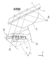
- FIG. 1 is a conceptual diagram for explaining the concept of the observation apparatus according to the present embodiment.
- the observation device 10 is fixed to the inner surface, which is the inner surface of the windshield 2 of the vehicle 1.
- the windshield 2 is an example of a translucent plate.
- the observation apparatus 10 is disposed in the vicinity of the lower side of the attachment portion 4 of the room mirror 3. Further, the observation apparatus 10 is disposed within the wiping range of the wiper 5.
- the X axis, Y axis, and Z axis in the figure correspond to the left-right direction, the up-down direction, and the front-rear direction of the vehicle 1, respectively.
- the right direction of the vehicle 1 is defined as the positive X-axis direction, the upward direction as the Y-axis positive direction, and the forward direction as the Z-axis positive direction with reference to the center of the light-receiving surface of the image sensor described later.
- the observation apparatus 10 captures an external space in front of the vehicle 1 as a main subject field. In the external space in front of the vehicle 1, there are roads, lanes, signs, vehicles traveling in front, and the like. Further, the observation device 10 takes an image of an area on the outer surface, which is the outer surface of the windshield 2, as a sub-field. Details will be described later.
- the observation apparatus 10 detects a deposit such as raindrops using a photographed image of the outer surface of the windshield 2. Then, the observation device 10 outputs the detection result to a wiper control device that controls the operation of the wiper 5.
- the wiper control device operates the wiper 5 according to the detection result of the observation device 10. Specifically, the wiper control device moves the wiper 5 quickly when it is determined as heavy rain from the detection result of the observation device 10, and moves slowly when it is determined as light rain.
- FIG. 2 is a first explanatory diagram illustrating the optical system of the observation apparatus according to the present embodiment.
- FIG. 2 is a perspective view of an optical system arranged inside the observation apparatus 10.
- the observation apparatus 10 includes a first light source 20, a second light source 30, a first observation optical system 40, a second observation optical system 50, and an imaging unit 60.
- the 1st light source 20 and the 2nd light source 30 are comprised by LED etc., and function as an irradiation part which irradiates near infrared light or infrared light to the surface area of the windshield 2.
- FIG. 1st light source 20 and the 2nd light source 30 are comprised by LED etc., and function as an irradiation part which irradiates near infrared light or infrared light to the surface area of the windshield 2.
- FIG. 1st light source 20 and the 2nd light source 30 are comprised by LED etc., and function as an irradiation part which irradiates near infrare
- the first observation optical system 40 includes a prism block 41, a first reflection mirror 42, a second reflection mirror 43, and a third reflection mirror 44.
- the first observation optical system 40 converts the irradiation light of the first light source 20 into parallel light, and guides the parallel light to the outer surface of the windshield 2.
- the parallel light in this embodiment includes not only completely parallel light but also substantially parallel light.
- region irradiated by the 1st observation optical system 40 among the outer surfaces of a windshield is called a 1st surface area
- the second observation optical system 50 includes a prism block 51, a first reflection mirror 52, a second reflection mirror 53, and a third reflection mirror 54.
- the second observation optical system 50 converts the irradiation light of the second light source 30 into parallel light, and guides the parallel light to the outer surface of the windshield 2.
- a region irradiated by the second observation optical system 50 on the outer surface of the windshield is referred to as a second surface region. Then, the second observation optical system 50 collects the reflected light reflected by the second surface region and emits it to the imaging unit 60.
- the imaging unit 60 includes one imaging optical system and one imaging element, as will be described later.
- a first observation optical system 40 and a second observation optical system 50 that are two observation optical systems are provided for one imaging optical system and one imaging element. It has been. Therefore, compared to the case where one observation optical system is used for one image pickup optical system and one image pickup device, the area of the observation region on the outer surface of the windshield is doubled, and the accuracy of raindrop detection is improved. Can be made. Further, compared to the case where two observation apparatuses each including one observation optical system, one image pickup optical system, and one image pickup element are used, the cost can be reduced because only one image pickup optical system and image pickup element can be used. it can.
- first surface region and the second surface region which are different surface regions on the outer surface of the windshield, using two observation optical systems, it is possible to improve the accuracy of raindrop detection.
- dirt is attached to one surface area, it is difficult to determine whether it is dirt or raindrops only with the photographed image of the one surface area, but it is difficult to determine whether dirt or raindrops by comparing the first surface area and the second surface area. Can be judged more accurately.
- the first observation optical system 40 and the second observation optical system 50 are arranged symmetrically with respect to the imaging unit 60 in the X-axis direction, that is, in the left-right direction of the vehicle 1.
- the imaging unit 60 is arranged at the center of the apparatus main body and two observation optical systems having the same configuration are arranged symmetrically with the imaging unit 60, the weight balance of the observation apparatus 10 is improved.
- the first observation optical system 40 is disposed on the X axis negative direction side with respect to the imaging unit 60, that is, on the left side of the vehicle 1, and the second observation optical system 50 is disposed on the imaging unit 60. It is arranged on the X axis positive direction side, that is, on the right side of the vehicle 1.
- the imaging optical system of the imaging unit 60 receives light from the front of the vehicle 1 as the main object field that passes through the region of the windshield 2 between the first surface region and the second surface region in the X-axis direction. To the image sensor.
- the first observation optical system 40 and the second observation optical system 50 on different sides with respect to the imaging unit 60, it is possible to simultaneously observe the distant regions and detect raindrops more accurately. .
- FIG. 3 is a second explanatory diagram illustrating the optical system of the observation apparatus according to the present embodiment.
- FIG. 3 is a view of the optical system arranged inside the observation apparatus 10 observed in the X-axis direction, that is, the left-right direction of the vehicle.
- the arrangement positions of the first light source 20, the prism block 41, the first reflection mirror 42, the second reflection mirror 43, and the third reflection mirror 44 are the second light source 30, the prism.
- the arrangement positions of the block 51, the first reflection mirror 52, the second reflection mirror 53, and the third reflection mirror 54 are the same.
- the observation apparatus 10 is installed on the windshield 2 via a silicon sheet 70.
- the silicon sheet 70 functions as a light-transmitting intermediate layer that reduces light reflection on the inner surface of the windshield 2.
- the prism block 41 converts the divergent light emitted from the first light source 20 into parallel light, and causes the irradiated light, which is parallel light, to enter the first surface region of the outer surface of the windshield via the silicon sheet 70.
- the incident angle of the irradiated light with respect to the first surface region is determined in advance to be greater than the critical angle at which the irradiated light is totally reflected by the first surface region when air contacts the outer surface of the windshield 2. In determining the incident angle, the refractive index of the windshield 2 and the refractive index of the air in contact with the outer surface of the windshield 2 are taken into consideration.
- the prism block 41 receives the reflected light reflected by the first surface region via the silicon sheet 70 and emits it to the first reflecting mirror 42.
- the first reflection mirror 42 reflects the light emitted from the prism block 41 toward the second reflection mirror 43.
- the second reflecting mirror 43 reflects the light from the first reflecting mirror 42 toward the third reflecting mirror 44.
- the third reflection mirror 44 reflects the light from the second reflection mirror 43 in the direction of the imaging unit 60.
- the reflection surfaces of the first reflection mirror 42 and the third reflection mirror 44 are formed as flat surfaces, and the 43 reflection surface of the second reflection mirror is formed as a concave surface. Therefore, the first reflection mirror 42, the second reflection mirror 43, and the third reflection mirror 44 collect the reflected light reflected by the first surface region and emit it to the imaging unit 60.
- a part of the prism block 41 functions as a relay optical system having a conversion function for converting the irradiation light from the first light source 20 into parallel light.
- a part of the prism block 41, the first reflecting mirror 42, the second reflecting mirror 43, and the third reflecting mirror 44 have a condensing function for condensing the reflected light reflected by the first surface region. It functions as a relay optical system.
- the second observation optical system 50 performs the same function as the first observation optical system 40 at a position different from the first observation optical system 40.
- the prism block 51 converts the divergent light emitted from the second light source 30 into parallel light, and causes the irradiated light, which is parallel light, to enter the second surface region of the outer surface of the windshield via the silicon sheet 70.
- the incident angle of the irradiated light with respect to the second surface region is the critical angle at which the irradiated light is totally reflected by the second surface region when air contacts the outer surface of the windshield 2, as is the case with the incident angle with respect to the first surface region described above. It is predetermined as described above.
- the prism block 51 receives the reflected light reflected by the second surface region via the silicon sheet 70 and emits it to the first reflecting mirror 52.
- the first reflection mirror 52 reflects the light emitted from the prism block 51 in the direction of the second reflection mirror 53.
- the second reflecting mirror 53 reflects the light from the first reflecting mirror 52 toward the third reflecting mirror 54.
- the third reflection mirror 54 reflects the light from the second reflection mirror 53 in the direction of the imaging unit 60.
- the reflecting surfaces of the first reflecting mirror 52 and the third reflecting mirror 54 are formed as flat surfaces, and the reflecting surface of the second reflecting mirror 53 is formed as a concave surface. Therefore, the first reflection mirror 52, the second reflection mirror 53, and the third reflection mirror 54 condense the reflected light reflected by the second surface region and emit it to the imaging unit 60.
- the prism block 51 functions as a relay optical system having a conversion function for converting irradiation light from the second light source 30 into parallel light.
- the first reflecting mirror 52, the second reflecting mirror 53, and the third reflecting mirror 54 function as a relay optical system having a condensing function for condensing the reflected light reflected by the second surface region. .
- the imaging unit 60 includes an imaging optical system 61 and an imaging element 62.
- the imaging optical system 61 is composed of a plurality of lenses, and is based on the incident side of light to the light receiving surface 63, which is the front side of the light receiving surface 63 of the image sensor 62, that is, the light receiving surface 63. It is disposed in the space on the Z axis positive direction side.
- the incident light is guided to the light receiving surface 63 of the image sensor 62.
- the imaging optical system 61 forms an image on the light receiving surface 63 of the imaging element 62 as light from the external space in front of the vehicle 1 that is incident through the windshield 2 as light from the main subject field.
- the first observation optical system 40 and the second observation optical system 50 are connected to the imaging optical system 61, respectively.
- the connection position of the imaging optical system 61 with the first observation optical system 40 that is, the position of the imaging optical system 61 on which the emitted light of the first observation optical system 40 is incident is the incident-side tip of the imaging optical system 61. May be halfway.
- the imaging optical system 61 the rear focal point where the light beam incident from the windshield 2 side with respect to the first observation optical system 40 is collected and the position of the entrance pupil of the imaging optical system 61 substantially coincide.
- a connection position with the first observation optical system 40 is determined.
- the connection position of the imaging optical system 61 with the second observation optical system 50 that is, the position of the imaging optical system 61 on which the emission light of the second observation optical system 50 is incident is also the incident-side tip of the imaging optical system 61. It may be halfway. Then, the imaging optical system 61 forms an image on the light receiving surface 63 of the imaging element 62 with the reflected light from the first surface area, which is light from the first surface area, as light from the first sub-field. Further, the imaging optical system 61 forms an image on the light receiving surface 63 of the imaging device 62 with the reflected light from the second surface region, which is light from the second surface region, as light from the second sub-field.
- the imaging element 62 is an element that photoelectrically converts a subject image formed on the light receiving surface 63 by the imaging optical system 61 and outputs an image signal.
- the image sensor 62 for example, a CCD or CMOS sensor is used.
- the light emitted from the first light source 20 and the second light source 30 is near infrared light or infrared light. Therefore, an infrared cut filter is not provided in the unit of the image sensor 62 on which the reflected light from the first surface region and the reflected light from the second surface region are imaged, and the R pixel is formed from near infrared and infrared. It is configured to sense including the wavelength region.
- One image signal output from the image sensor 62 includes a main image signal corresponding to the main scene, a sub-image signal corresponding to the first sub-field and the second sub-field. Specifically, three areas of the main scene, the first sub-field, and the second sub-field are captured in one frame of the image signal.
- Image data is generated by processing an image signal output from the image sensor 62 by an image generation unit described later.
- the first light source 20 is disposed on the back side of the light receiving surface 63 opposite to the front side of the light receiving surface 63 of the image sensor 62, that is, in the space on the negative side of the Z axis with respect to the light receiving surface 63.
- the second light source 30 is also arranged in the space behind the light receiving surface 63.
- the first light source 20 and the second light source 30 are arranged in the space behind the light receiving surface 63 of the image sensor 62, so that the light emitted from the first light source 20 and the second light source 30 is transmitted to the image sensor 62. Direct incidence on the light receiving surface 63 can be prevented. Therefore, the image sensor 62 can appropriately receive the reflected light from the first surface region and the reflected light from the second surface region, and the detection accuracy of the deposits such as raindrops in the first surface region and the second surface region. Can be increased.
- FIG. 4 is an explanatory diagram for explaining the external appearance of the observation apparatus according to the first embodiment.
- the casing 80 of the observation apparatus 10 according to the first example includes the first light source 20, the second light source 30, the first observation optical system 40, the second observation optical system 50, and the imaging unit 60 described above.
- the housing 80 is provided with an opening 81.
- the imaging unit 60 images the outside of the housing 80 through the opening 81.
- the observation device 10 is disposed in the vicinity of the lower side of the mounting portion 4 of the room mirror 3.
- a silicon sheet 70 is provided on the surface of the mounting portion 82 of the housing 80, and the observation apparatus 10 is installed on the windshield 2 via the silicon sheet 70.
- the imaging unit 60 images the external space in front of the vehicle 1, the first surface region, and the second surface region through the opening 81.
- a portion of the housing 80 opposite to the opening 81 is formed flat and adjacent to the mounting portion 4 of the rearview mirror 3.
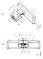
- FIG. 5 is an explanatory diagram for explaining the external appearance of the observation apparatus according to the second embodiment.
- the housing 90 of the observation apparatus 10 according to the second example includes the first light source 20, the second light source 30, the first observation optical system 40, the second observation optical system 50, and the imaging unit 60 described above.
- the housing 90 is provided with an opening 91.
- the imaging unit 60 images the outside of the housing 90 through the opening 91.
- the observation device 10 is disposed in the vicinity of the lower side of the attachment portion 4 of the rearview mirror 3.
- a silicon sheet 70 is provided on the surface of the mounting portion 92 of the housing 90, and the observation apparatus 10 is installed on the windshield 2 via the silicon sheet 70.
- the imaging unit 60 images the external space in front of the vehicle 1, the first surface region, and the second surface region through the opening 91.
- a concave portion 93 into which at least a part of the attachment portion 4 can be inserted is formed in the portion of the housing 90 opposite to the opening 91.
- the observation apparatus 10 is installed on the windshield in a state where a part of the attachment portion 4 is inserted into the recess 93.
- the concave casing 90 includes a central portion 94, a first side portion 95, and a second side portion 96.
- the central portion 94 includes the bottom of the recess 93.
- the first side portion 95 includes one side portion of the concave portion 93
- the second side portion 96 includes the other side portion of the concave portion 93.
- the central portion 94 is on the first side. It is shorter than the part 95 and the second side part 96.
- the central portion 94, the first side portion 95, and the second side portion 96 may be formed integrally or may be joined after being formed separately.
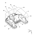
- FIG. 6 is an explanatory diagram for explaining the arrangement of the optical system of the observation apparatus according to the second embodiment.
- the imaging unit 60 is disposed on the mounting portion 92 in the central portion 94.
- the third reflection mirror 44 and the third reflection mirror 54 closest to the imaging unit 60 are in a space on the Z-axis positive direction side with respect to the imaging unit 60, that is, in a space on the front side of the light receiving surface 63 of the imaging element 62 described above.
- the first reflecting mirror 42, the second reflecting mirror 43, the first reflecting mirror 52, and the second reflecting mirror 53 are not shown in FIG. 6, but are arranged at predesigned positions in the housing 90. .
- the prism block 41 is disposed on the mounting portion 92 in the first side portion 95.
- the first light source 20 is disposed in a portion of the first side portion 95 protruding from the central portion 94.
- the prism block 51 is disposed on the mounting portion 92 in the second side portion 96.
- the second light source 30 is disposed at a portion of the second side portion 96 protruding from the central portion 94.
- FIG. 7 is a block diagram showing a configuration of the observation apparatus according to the present embodiment.
- the observation apparatus 10 includes an image generation unit 100, an image recording unit 110, and a control unit 120 in addition to the configuration described above.
- the image generation unit 100 includes an A / D converter 101 and an image processing unit 102.
- the A / D converter 101 converts the image signal output from the image sensor 62 that is an analog signal into a digital signal.
- the subject image converted into the digital signal is sequentially processed as image data.
- the image data converted into a digital signal by the A / D converter 101 is delivered to the image processing unit 102.
- the image processing unit 102 converts the image data into image data in a standardized image format. For example, when generating a JPEG file as a still image, image processing such as color conversion processing, gamma processing, and white balance processing is performed, and then adaptive discrete cosine conversion is performed to perform compression processing. When an MPEG file is generated as a moving image, compression processing is performed by applying intra-frame coding and inter-frame coding to the generated frame images as continuous still images.
- the A / D converter 101 also outputs a main image signal corresponding to the external space in front of the vehicle 1 that is the main scene from the image signal output from the image sensor 62, and a first sub-field that is the first sub-field. You may distinguish and extract the 1st surface area and the subimage signal corresponding to the 2nd surface area which is the 2nd subfield. Then, the image processing unit 102 performs main image processing on the image data obtained by converting the main image signal into a digital signal to generate main image data. On the other hand, the image processing unit 102 generates sub-image data by performing sub-image processing different from main image processing on the image data obtained by converting the sub-image signal into a digital signal.
- the image processing unit 102 calculates color values such as RGB for each pixel of the image data obtained by converting the main image signal into a digital signal, and generates color main image data.
- the image processing unit 102 generates black and white sub-image data corresponding to the luminance value of each pixel of the image data obtained by converting the sub-image signal into a digital signal.
- the image processing unit 102 collects the outputs of the above-described R pixels configured to sense including the near infrared and infrared wavelength regions, and generates black and white sub-image data.
- the image generation unit 100 may generate image data by extracting either the main image signal or the sub-image signal from the image signal output from the image sensor 62. For example, the image generation unit 100 extracts a main image signal from an image signal of a certain period, and generates main image data that is captured image data of the main scene. For example, the image generation unit 100 extracts a sub-image signal from an image signal in another period, and generates sub-image data that is captured image data of the sub-field.
- Still image data and moving image data generated by the image generation unit 100 are recorded in the image recording unit 110.
- the image recording unit 110 is configured by a flash memory or the like.
- the control unit 120 is attached to the first surface region and the second surface region of the windshield 2 using at least one of the image data output from the image generation unit 100 and the image data recorded in the image recording unit 110. Detect deposits. Then, the control unit 120 outputs the detection result to the wiper control device that controls the operation of the wiper 5.
- the difference between the refractive index of the windshield 2 and the refractive index of the deposit is the difference between the refractive index of the windshield 2 and the refractive index of air. Smaller than the difference. For this reason, the condition of total reflection of irradiation light in the first surface region is not satisfied, and a part of the irradiation light reaching the first surface region is transmitted without being reflected.
- the intensity of the reflected light at the first surface region that is incident on the imaging unit 60 when the adhering matter is attached due to the transmission of a part of the irradiation light is the same as that of the imaging unit 60 when the adhering matter is not attached.
- the brightness value of the area where the image of the deposit is present in the image of the first surface area represented by the image data is smaller than the brightness value of the area where the image of the deposit is not present. The same applies to the second display area.
- the control unit 120 has a reference in which an area having a luminance value equal to or less than a predetermined threshold exists in the image of the first display area and the image of the second display area, and the size of the area is predetermined.
- the area is detected as an attachment area where an image of the attachment exists.
- the threshold value and reference area of the luminance value are determined in advance according to the refractive index, size, etc. of the detection object such as raindrops.
- FIG. 8 is a diagram showing a screen example of a captured image of the observation apparatus.
- the control unit 120 outputs at least one of the image data output from the image generation unit 100 and the image data recorded in the image recording unit 110 to a display device mounted on the vehicle 1.
- the display device displays an image of the external space ahead of the vehicle 1 represented by the main image data in the main area 201 of the display screen. Further, the display device displays an image of the first surface area of the windshield 2 represented by the sub-image data in the lower left peripheral area 202 of the display screen. Further, the display device displays an image of the second surface area of the windshield 2 represented by the sub-image data in the lower right peripheral area 203 of the display screen.
- the display position of the image in the first display area is made to correspond to the left side that is the position of the first observation optical system 40 with respect to the imaging unit 60, and the display position of the image in the second display area is set to the imaging unit. 60 may correspond to the right side, which is the position of the second observation optical system 50 with respect to 60.
- the imaging optical system 61 guides the light from the first observation optical system 40 to the first peripheral region in the imaging region of the light receiving surface 63 of the image sensor 62 corresponding to the lower left peripheral region 202 of the display device. Similarly, the imaging optical system 61 guides the light from the second observation optical system 50 to the second peripheral area in the imaging area of the light receiving surface 63 of the imaging element 62 corresponding to the lower right peripheral area 203 of the display device. Furthermore, the imaging optical system 61 guides light from the external space in front of the vehicle 1 to the imaging area of the light receiving surface 63 of the imaging element 62 corresponding to the main area 201 of the display device.
- the image generation unit 100 processes the frame of the image signal output from the image sensor 62 as it is to generate the image data of FIG.
- the image generation unit 100 generates image data by extracting either the main image signal or the sub-image signal from one frame of the image signal output from the image sensor 62, without being limited to processing the frame of the image signal as it is. May be. For example, when the weather is fine, the image generation unit 100 extracts sub-image signals for one frame per second and generates sub-image data for determining whether or not it has rained. A main image signal is extracted from the frame to generate main image data. Further, for example, when the weather is rain, the image generation unit 100 alternately generates main image data and sub image data in units of frames, and acquires sub image data for determining the rain condition.
- the image generation unit 100 may crop either the main image data or the sub image data among the image data generated from one frame of the image signal output from the image sensor 62. For example, when the weather is clear, the image generation unit 100 crops the sub-image data for determining whether or not it has rained from the image data for one frame per second, and images of other frames Crop main image data from data. For example, when the weather is rainy, the image generation unit 100 alternately crops main image data and sub-image data in units of frames, and acquires sub-image data for determining the rain condition.
- image data suitable for the situation can be generated.
- a clear image can be acquired by selecting, for each frame, a shooting condition such as an exposure value for the image represented by the main image data and a shooting condition such as an exposure value for the image represented by the sub-image data.
- the first light source 20 and the second light source 30 emit divergent light, and the prism blocks 41 and 51 are converted into parallel light.
- the present invention is not limited to this, and the first light source 20 and the second light source 30 are parallel.
- the part which irradiates light and converts into parallel light among the prism blocks 41 and 51 may be omitted.
- the prism blocks 41 and 51 emit the reflected light of the parallel light from the first surface region and the second surface region to the first reflection mirrors 42 and 52 as parallel light, but the first surface region is not limited thereto.
- the reflected light of the parallel light from the second surface region may be condensed and emitted.
- the reflecting surfaces of the second reflecting mirrors 43 and 53 are formed as concave surfaces.
- the first reflecting mirrors 42 and 52, the second reflecting mirrors 43 and 53, and the third reflecting mirrors 44 and 54 are not limited to this.
- at least one reflection surface may be formed as a concave surface.
- the number is not limited to three, and the number of reflection mirrors according to product restrictions may be provided.
- the observation apparatus 10 is provided with two observation optical systems, but the number of observation optical systems is not limited to two and may be one. In this case, one of the first side portion 95 and the second side portion 96 in the second embodiment described with reference to FIGS. 5 and 6 may be removed to form an L-shaped casing. Further, the observation apparatus 10 may be provided with three or more observation optical systems.
- the image generation unit 100 may determine the display position on the display screen of the image represented by the main image data and the image represented by the sub image data.
- the image represented by the sub image data can be displayed at a position different from the display position corresponding to the image position of the sub field on the light receiving surface 63 of the image sensor 62.
- the adhering matter detection process is executed by the control unit 120 of the observation apparatus 10.
- the observation apparatus 10 outputs image data to the data processing apparatus of the vehicle 1, and the adhering substance detection process is performed on the data processing apparatus. It may be executed.
- the observation device 10 may switch which of the main image data and the sub image data is output in accordance with a command from the data processing device. Further, the observation device 10 may output the image signal output from the image sensor 62 to the data processing device of the vehicle 1 and cause the data processing device to execute the image generation processing performed by the image generation unit 100 described above.
- the observation device 10 is disposed on the windshield 2 that is the windshield of the vehicle 1, but is not limited thereto, and may be disposed on the rear glass of the vehicle 1.
- the mounting object of the observation apparatus 10 was demonstrated as a vehicle, naturally it can apply not only to the application to a vehicle but to various mobile bodies which have translucent bodies, such as an aircraft.
Landscapes
- Engineering & Computer Science (AREA)
- Automation & Control Theory (AREA)
- Mechanical Engineering (AREA)
- Investigating Or Analysing Materials By Optical Means (AREA)
Abstract
従来の観察装置において、ウィンドシールドの外表面に光を照射する光源が撮像素子より前方に配置されている。そのため、光源から射出された発散光が撮像素子の受光面に直接入射して雨滴検出の精度が落ちてしまうという問題があった。 そこで、ウィンドシールドの外表面領域へ向けて照射光を照射する照射部と、外表面領域で反射した照射光を受光面で受光する撮像素子と、を備え、照射部は、撮像素子の受光面と反対側に配置されている、ウィンドシールドの外表面に付着する付着物を検出する観察装置を提供する。
Description
本発明は、観察装置に関する。
1つの撮像素子を用いて車両前方の外部空間とウィンドシールドの外表面とを観察する観察装置が知られている。この観察装置を用いてウィンドシールドの外表面を観察することにより雨滴を検出し、ワイパーを作動させて視界を確保することが行われる。
[先行技術文献]
[特許文献]
[特許文献1]特開2009-294159号公報
[先行技術文献]
[特許文献]
[特許文献1]特開2009-294159号公報
しかしながら、従来の観察装置において、ウィンドシールドの外表面に光を照射する光源が撮像素子より前方に配置されている。そのため、光源から射出された発散光が撮像素子の受光面に直接入射して雨滴検出の精度が落ちてしまうという問題があった。
本発明の態様におけるウィンドシールドの外表面に付着する付着物を検出する観察装置は、ウィンドシールドの外表面領域へ向けて照射光を照射する照射部と、外表面領域で反射した照射光を受光面で受光する撮像素子と、を備え、照射部は、撮像素子の受光面と反対側に配置されている。
なお、上記の発明の概要は、本発明の必要な特徴の全てを列挙したものではない。また、これらの特徴群のサブコンビネーションもまた、発明となりうる。
以下、発明の実施の形態を通じて本発明を説明するが、以下の実施形態は請求の範囲にかかる発明を限定するものではない。また、実施形態の中で説明されている特徴の組み合わせの全てが発明の解決手段に必須であるとは限らない。
図1は、本実施形態に係る観察装置の概念を説明する概念図である。観察装置10は、車両1のウィンドシールド2の車内側の表面である内表面に固定される。ウィンドシールド2は透光板の一例である。本実施形態において、観察装置10は、ルームミラー3の取付部4の下側近傍に配置されている。また、観察装置10は、ワイパー5の払拭範囲内に配置されている。図中のX軸、Y軸およびZ軸は、車両1の左右方向、上下方向および前後方向にそれぞれ対応する。なお、後述する撮像素子の受光面の中心を基準として、車両1の右方向をX軸正方向、上方向をY軸正方向、前方向をZ軸正方向とする。
観察装置10は、車両1の前方の外部空間を主被写界として撮影する。車両1の前方の外部空間には、道路、車線、標識、前を走行する車両等が存在する。また、観察装置10は、ウィンドシールド2の車外側の表面である外表面の領域を副被写界として撮影する。なお、詳細は後述する。
観察装置10は、ウィンドシールド2の外表面の撮影画像を用いて雨滴等の付着物を検出する。そして、観察装置10は、ワイパー5の動作を制御するワイパー制御装置に検出結果を出力する。ワイパー制御装置は、観察装置10の検出結果に応じてワイパー5を作動させる。具体的には、ワイパー制御装置は、観察装置10の検出結果から大雨と判断した場合にはワイパー5を早く動かし、小雨と判断した場合にはゆっくり動かす。
図2は、本実施形態に係る観察装置の光学系を説明する第1の説明図である。図2は、観察装置10の内部に配置されている光学系の斜視図である。図2に示すとおり、観察装置10は、第1光源20、第2光源30、第1観察光学系40、第2観察光学系50、撮像部60を備える。第1光源20および第2光源30は、LED等で構成されており、ウィンドシールド2の表面領域に近赤外光または赤外光を照射する照射部として機能する。
第1観察光学系40は、プリズムブロック41、第1反射ミラー42、第2反射ミラー43および第3反射ミラー44を備える。第1観察光学系40は、第1光源20の照射光を平行光に変換し、平行光をウィンドシールド2の外表面に導く。なお、本実施形態における平行光は、完全に平行な光だけでなく、実質的に平行な光も含む。また、ウィンドシールドの外表面のうち第1観察光学系40によって照射される領域を第1表面領域と称する。そして、第1観察光学系40は、第1表面領域で反射した反射光を集光して撮像部60に射出する。
同様に、第2観察光学系50は、プリズムブロック51、第1反射ミラー52、第2反射ミラー53および第3反射ミラー54を備える。第2観察光学系50は、第2光源30の照射光を平行光に変換し、平行光をウィンドシールド2の外表面に導く。なお、ウィンドシールドの外表面のうち第2観察光学系50によって照射される領域を第2表面領域と称する。そして、第2観察光学系50は、第2表面領域で反射した反射光を集光して撮像部60に射出する。
撮像部60は、後述するとおり、1つの撮像光学系と1つの撮像素子とを備える。図2に示すとおり、本実施形態の観察装置10において、1つの撮像光学系および1つの撮像素子に対して2つの観察光学系である第1観察光学系40および第2観察光学系50が設けられている。したがって、1つの撮像光学系および1つの撮像素子に対して1つの観察光学系を用いた場合と比べると、ウィンドシールドの外表面における観察領域の面積が2倍になり、雨滴検出の精度を向上させることができる。また、1つの観察光学系、1つの撮像光学系および1つの撮像素子を備える観察装置を2つ用いた場合と比べると、撮像光学系および撮像素子を1つで済ませられるのでコストを下げることができる。
また、2つの観察光学系を用いてウィンドシールドの外表面における異なる表面領域である第1表面領域および第2表面領域を観察することにより、雨滴検出の精度を向上させることができる。片方の表面領域に汚れが付着している場合、当該片方の表面領域の撮影画像のみでは汚れか雨滴かを判断し難いが、第1表面領域および第2表面領域を比較することで汚れか雨滴かをより正確に判断することができる。
さらに、図2に示すとおり、第1観察光学系40および第2観察光学系50は、X軸方向、すなわち車両1の左右方向において、撮像部60に対して対称に配置される。撮像部60が装置本体の中央部に配置されるとともに同じ構成を備える2つの観察光学系が撮像部60に対称に配置されることにより、観察装置10の重量バランスが良くなる。
また、図2に示すとおり、第1観察光学系40を撮像部60に対してX軸負方向の側、すなわち車両1の左側に配置するとともに、第2観察光学系50を撮像部60に対してX軸正方向の側、すなわち車両1の右側に配置する。そして、撮像部60の撮像光学系は、X軸方向において第1表面領域および第2表面領域の間のウィンドシールド2の領域を透過する主被写界としての車両1の前方からの光を受光し撮像素子に導く。このように、第1観察光学系40および第2観察光学系50を撮像部60に対して異なる側に配置することにより、離れた領域を同時に観察してより正確に雨滴を検出することができる。
図3は、本実施形態に係る観察装置の光学系を説明する第2の説明図である。図3は、観察装置10の内部に配置されている光学系をX軸方向、すなわち車両の左右方向に観察した図である。本実施形態において、X軸方向から見た場合、第1光源20、プリズムブロック41、第1反射ミラー42、第2反射ミラー43および第3反射ミラー44の配置位置は、第2光源30、プリズムブロック51、第1反射ミラー52、第2反射ミラー53および第3反射ミラー54の配置位置とそれぞれ同一である。
図3に示すとおり、観察装置10は、シリコンシート70を介してウィンドシールド2に設置されている。シリコンシート70は、ウィンドシールド2の内表面での光の反射を低減させる光透過性の中間層として機能する。
まず、第1観察光学系40について説明する。プリズムブロック41は、第1光源20から照射された発散光を平行光に変換し、平行光である照射光をシリコンシート70を介してウィンドシールドの外表面の第1表面領域に入射させる。照射光の第1表面領域に対する入射角は、ウィンドシールド2の外表面に空気が接する場合において照射光が第1表面領域で全反射する臨界角以上に予め決定される。入射角の決定において、ウィンドシールド2の屈折率およびウィンドシールド2の外表面に接する空気の屈折率が考慮される。プリズムブロック41は、第1表面領域で反射した反射光をシリコンシート70を介して受光し、第1反射ミラー42へ射出する。
第1反射ミラー42は、プリズムブロック41から射出された光を第2反射ミラー43の方向へ反射する。第2反射ミラー43は、第1反射ミラー42からの光を第3反射ミラー44の方向へ反射する。第3反射ミラー44は、第2反射ミラー43からの光を撮像部60の方向へ反射する。図3に示すとおり、第1反射ミラー42および第3反射ミラー44の反射面は平面で形成され、第2反射ミラーの43反射面は凹面に形成される。したがって、第1反射ミラー42、第2反射ミラー43および第3反射ミラー44は、第1表面領域で反射した反射光を集光して撮像部60に射出する。
本実施形態において、プリズムブロック41の一部は、第1光源20からの照射光を平行光に変換する変換機能を有する中継光学系として機能する。また、本実施形態において、プリズムブロック41の一部、第1反射ミラー42、第2反射ミラー43および第3反射ミラー44は、第1表面領域で反射した反射光を集光する集光機能を有する中継光学系として機能する。
次に、第2観察光学系50について説明する。第2観察光学系50は、第1観察光学系40と異なる位置において、第1観察光学系40と同様の機能を実行する。プリズムブロック51は、第2光源30から照射された発散光を平行光に変換し、平行光である照射光をシリコンシート70を介してウィンドシールドの外表面の第2表面領域に入射させる。照射光の第2表面領域に対する入射角は、上述の第1表面領域に対する入射角と同様に、ウィンドシールド2の外表面に空気が接する場合において照射光が第2表面領域で全反射する臨界角以上に予め定められる。プリズムブロック51は、第2表面領域で反射した反射光をシリコンシート70を介して受光し、第1反射ミラー52へ射出する。
第1反射ミラー52は、プリズムブロック51から射出された光を第2反射ミラー53の方向へ反射する。第2反射ミラー53は、第1反射ミラー52からの光を第3反射ミラー54の方向へ反射する。第3反射ミラー54は、第2反射ミラー53からの光を撮像部60の方向へ反射する。図3に示すとおり、第1反射ミラー52および第3反射ミラー54の反射面は平面で形成され、第2反射ミラー53の反射面は凹面に形成される。したがって、第1反射ミラー52、第2反射ミラー53および第3反射ミラー54は、第2表面領域で反射した反射光を集光して撮像部60に射出する。
本実施形態において、プリズムブロック51は、第2光源30からの照射光を平行光に変換する変換機能を有する中継光学系として機能する。また、本実施形態において、第1反射ミラー52、第2反射ミラー53および第3反射ミラー54は、第2表面領域で反射した反射光を集光する集光機能を有する中継光学系として機能する。
撮像部60は、撮像光学系61と撮像素子62とを備える。撮像光学系61は、図3に示すとおり、複数のレンズから構成されており、撮像素子62の受光面63の表側である受光面63への光の入射側、すなわち受光面63を基準としたZ軸正方向側の空間に配置されている。入射した光を撮像素子62の受光面63に導く。撮像光学系61は、ウィンドシールド2を透過して入射する車両1の前方の外部空間からの光を、主被写界からの光として撮像素子62の受光面63で結像する。
第1観察光学系40および第2観察光学系50は、それぞれ撮像光学系61に接続する。なお、撮像光学系61における第1観察光学系40との接続位置、すなわち第1観察光学系40の射出光が入射する撮像光学系61の位置は、撮像光学系61の入射側先端であっても中途であってもよい。例えば、第1観察光学系40に対してウィンドシールド2側から入射した光線が集光される後側焦点と撮像光学系61の入射瞳の位置とがほぼ一致するように、撮像光学系61における第1観察光学系40との接続位置が定められている。
同様に、撮像光学系61における第2観察光学系50との接続位置、すなわち第2観察光学系50の射出光が入射する撮像光学系61の位置も、撮像光学系61の入射側先端であっても中途であってもよい。そして、撮像光学系61は、第1表面領域からの光である第1表面領域での反射光を、第1副被写界からの光として撮像素子62の受光面63で結像する。さらに、撮像光学系61は、第2表面領域からの光である第2表面領域での反射光を、第2副被写界からの光として撮像素子62の受光面63で結像する。
撮像素子62は、撮像光学系61によって受光面63で結像した被写体像を光電変換し、画像信号を出力する素子である。撮像素子62として、例えば、CCD、CMOSセンサが用いられる。上述したとおり、第1光源20および第2光源30から照射される光は近赤外光または赤外光である。そこで、第1表面領域での反射光および第2表面領域での反射光が結像する撮像素子62のユニットには赤外カットフィルタが設けられておらず、かつR画素が近赤外および赤外線波長領域を含めて感知するように構成されている。
撮像素子62から出力される1つの画像信号には、主被写界に対応する主画像信号、第1副被写界および第2副被写界に対応する副画像信号が含まれる。具体的には、画像信号の1フレームに、主被写界、第1副被写界および第2副被写界の3つの領域が写り込んでいる。撮像素子62から出力された画像信号が後述する画像生成部によって処理されることにより、画像データが生成される。
図3に示すとおり、第1光源20は、撮像素子62の受光面63の表側とは反対の受光面63の裏側、すなわち受光面63を基準としたZ軸負方向側の空間に配置されている。同様に、第2光源30も、受光面63の裏側の空間に配置されている。このように第1光源20および第2光源30が撮像素子62の受光面63の裏側の空間に配置されることにより、第1光源20および第2光源30から射出された光が撮像素子62の受光面63に直接入射することを防ぐことができる。したがって、撮像素子62は第1表面領域からの反射光および第2表面領域からの反射光を適切に受光することができ、第1表面領域および第2表面領域における雨滴等の付着物の検出精度を高めることができる。
図4は、第1実施例に係る観察装置の外観を説明する説明図である。第1実施例に係る観察装置10の筐体80は、上述した第1光源20、第2光源30、第1観察光学系40、第2観察光学系50および撮像部60を内包する。筐体80には、開口部81が設けられている。撮像部60は、開口部81を介して筐体80の外界を撮影する。
図4に示すとおり、観察装置10は、ルームミラー3の取付部4の下側近傍に配置される。筐体80の装着部82の表面にシリコンシート70が設けられ、観察装置10はシリコンシート70を介してウィンドシールド2に設置されている。観察装置10がウィンドシールド2に設置された状態において、撮像部60は、開口部81を介して車両1の前方の外部空間、第1表面領域および第2表面領域を撮影する。筐体80における開口部81と反対側の部分は、平坦に形成され、ルームミラー3の取付部4に隣接する。
図5は、第2実施例に係る観察装置の外観を説明する説明図である。第2実施例に係る観察装置10の筐体90は、上述した第1光源20、第2光源30、第1観察光学系40、第2観察光学系50および撮像部60を内包する。筐体90には、開口部91が設けられている。撮像部60は、開口部91を介して筐体90の外界を撮影する。
図5に示すとおり、観察装置10は、ルームミラー3の取付部4の下側近傍に配置される。筐体90の装着部92の表面にシリコンシート70が設けられ、観察装置10はシリコンシート70を介してウィンドシールド2に設置されている。観察装置10がウィンドシールド2に設置された状態において、撮像部60は、開口部91を介して車両1の前方の外部空間、第1表面領域および第2表面領域を撮影する。
開口部91と反対側の筐体90の部分には、取付部4の少なくとも一部が挿入可能な凹部93が形成されている。第2実施例において、この凹部93に取付部4の一部が挿入された状態で観察装置10がウィンドシールドに設置される。このように取付部4の少なくとも一部が挿入可能な凹部93を形成することにより、車両1の上下方向においてルームミラー3からはみ出る観察装置10の領域を少なくして、観察装置10による運転者の視界の妨げを低減することができる。
図5(b)に示すとおり、凹型の筐体90は、中央部94、第1側部95および第2側部96で構成される。中央部94は、凹部93の底部を含む。第1側部95は凹部93の一方の側部を含み、第2側部96は凹部93の他方の側部を含む。撮像部60、第1観察光学系40および第2観察光学系50の配列方向であるX軸方向に垂直かつ装着部92の表面に沿った方向である方向Aにおいて、中央部94は第1側部95および第2側部96より短い。なお、中央部94、第1側部95および第2側部96は、一体に形成されても、別体で形成された後に接合されてもよい。
図6は、第2実施例に係る観察装置の光学系の配置を説明する説明図である。図6に示すとおり、中央部94における装着部92には、撮像部60が配置されている。また、撮像部60に最も近い第3反射ミラー44および第3反射ミラー54は、撮像部60に対してZ軸正方向側の空間、すなわち上述した撮像素子62の受光面63の表側の空間における筐体90の同一面に配置されている。なお、第1反射ミラー42、第2反射ミラー43、第1反射ミラー52および第2反射ミラー53は、図6には図示しないが、筐体90内の予め設計された位置に配置されている。
第1側部95における装着部92には、プリズムブロック41が配置されている。また、中央部94から突出した第1側部95の部分に第1光源20が配置されている。同様に、第2側部96における装着部92には、プリズムブロック51が配置されている。また、中央部94から突出した第2側部96の部分に第2光源30が配置されている。このように筐体90を凹型に形成することにより、観察装置10が車両1に設置された状態において、第1光源20および第2光源30が撮像部60の撮像素子62より後方に配置させることが容易となる。
図7は、本実施形態に係る観察装置の構成を示すブロック図である。観察装置10は、上述した構成に加え、画像生成部100、画像記録部110および制御部120を備える。画像生成部100は、A/D変換器101と画像処理部102とを備える。A/D変換器101は、アナログ信号である撮像素子62から出力された画像信号をデジタル信号へ変換する。デジタル信号に変換された被写体像は、画像データとして順次処理される。
A/D変換器101によりデジタル信号に変換された画像データは、画像処理部102へ引き渡される。画像処理部102は、画像データを規格化された画像フォーマットの画像データに変換する。例えば、静止画像としてJPEGファイルを生成する場合、色変換処理、ガンマ処理、ホワイトバランス処理等の画像処理を行った後に適応離散コサイン変換等を施して圧縮処理を行う。また、動画像としてMPEGファイルを生成する場合、生成された連続する静止画としてのフレーム画像に対して、フレーム内符号化、フレーム間符号化を施して圧縮処理を行う。
また、A/D変換器101は、撮像素子62から出力された画像信号から主被写界である車両1の前方の外部空間に対応する主画像信号と、第1副被写界である第1表面領域および第2副被写界である第2表面領域に対応する副画像信号とを区別して抽出してもよい。そして、画像処理部102は、主画像信号をデジタル信号に変換された画像データに対して主画像処理を実行して主画像データを生成する。一方、画像処理部102は、副画像信号をデジタル信号に変換された画像データに対して主画像処理と異なる副画像処理を実行して副画像データを生成する。
例えば、画像処理部102は、主画像信号をデジタル信号に変換された画像データの各画素に対してRGB等のカラー値を算出してカラーの主画像データを生成する。一方、画像処理部102は、副画像信号をデジタル信号に変換された画像データの各画素の輝度値に応じた白黒の副画像データを生成する。具体的には、画像処理部102は、近赤外および赤外線波長領域を含めて感知するように構成された上述のR画素の出力を集めて白黒の副画像データを生成する。
画像生成部100は、撮像素子62から出力された画像信号のうち主画像信号および副画像信号のいずれかを抽出して画像データを生成してもよい。例えば、画像生成部100は、ある期間の画像信号から主画像信号を抽出し、主被写界の撮影画像データである主画像データを生成する。また、例えば、画像生成部100は、別の期間の画像信号から副画像信号を抽出し、副被写界の撮影画像データである副画像データを生成する。
画像生成部100によって生成された静止画像データ、動画像データは、画像記録部110に記録される。画像記録部110は、フラッシュメモリ等により構成される。制御部120は、画像生成部100から出力された画像データおよび画像記録部110に記録されている画像データの少なくとも一方を用いて、ウィンドシールド2の第1表面領域および第2表面領域に付着した付着物を検出する。そして、制御部120は、ワイパー5の動作を制御するワイパー制御装置に検出結果を出力する。
ウィンドシールド2の第1表面領域に雨滴等の付着物が付着している場合、ウィンドシールド2の屈折率と付着物の屈折率との差がウィンドシールド2の屈折率と空気の屈折率との差より小さくなる。そのため、第1表面領域における照射光の全反射の条件を満たさなくなり、第1表面領域に達した照射光の一部が反射せずに透過してしまう。照射光の一部の透過により、付着物が付着している場合において撮像部60に入射される第1表面領域での反射光の強度は、付着物が付着していない場合において撮像部60に入射される第1表面領域での反射光の強度より小さくなる。したがって、画像データが表す第1表面領域の画像において付着物の画像が存在する領域の輝度値は、付着物の画像が存在しない領域の輝度値に比べて小さくなる。第2表示領域においても同様である。
そこで、制御部120は、第1表示領域の画像および第2表示領域の画像において、予め定められた閾値以下の輝度値をもつ領域が存在し、かつその領域の大きさが予め定められた基準面積以上の場合に、その領域を付着物の画像が存在する付着物領域として検出する。輝度値の閾地および基準面積は、雨滴等の検出対象物の屈折率、大きさ等に応じて予め定められる。
図8は、観察装置の撮影画像の画面例を示す図である。制御部120は、画像生成部100から出力された画像データおよび画像記録部110に記録されている画像データの少なくとも一方を車両1に搭載された表示装置に出力する。
図8に示すとおり、表示装置は、主画像データが表す車両1の前方の外部空間の画像を表示画面の主領域201に表示する。また、表示装置は、副画像データが表すウィンドシールド2の第1表面領域の画像を表示画面の左下周縁領域202に表示する。さらに、表示装置は、副画像データが表すウィンドシールド2の第2表面領域の画像を表示画面の右下周縁領域203に表示する。なお、図8に示すように、第1表示領域の画像の表示位置を撮像部60に対する第1観察光学系40の位置である左側に対応させ、第2表示領域の画像の表示位置を撮像部60に対する第2観察光学系50の位置である右側に対応させてもよい。
撮像光学系61は、第1観察光学系40からの光を、表示装置の左下周縁領域202に対応する撮像素子62の受光面63の撮像領域における第1周縁領域に導く。同様に、撮像光学系61は、第2観察光学系50からの光を、表示装置の右下周縁領域203に対応する撮像素子62の受光面63の撮像領域における第2周縁領域に導く。さらに、撮像光学系61は、車両1の前方の外部空間からの光を、表示装置の主領域201に対応する撮像素子62の受光面63の撮像領域に導く。画像生成部100は、撮像素子62から出力された画像信号のフレームをそのまま処理して図8の画像データを生成する。
画像生成部100は、画像信号のフレームをそのまま処理することに限らず、撮像素子62から出力された画像信号の1フレームから主画像信号および副画像信号のいずれかを抽出して画像データを生成してもよい。例えば、天気が晴れである場合、画像生成部100は、1秒間に1フレームだけ副画像信号を抽出して雨が降ってきたか否かを判断するための副画像データを生成し、それ以外のフレームから主画像信号を抽出して主画像データを生成する。また、例えば、天気が雨である場合、画像生成部100は、主画像データと副画像データとをフレーム単位で交互に生成し、雨の状況を判断するための副画像データを取得する。
また、画像生成部100は、撮像素子62から出力された画像信号の1フレームから生成した画像データのうち、主画像データおよび副画像データのいずれかをクロップしてもよい。例えば、天気が晴れである場合、画像生成部100は、1秒間に1フレーム分の画像データから雨が降ってきたか否かを判断するための副画像データをクロップし、それ以外のフレームの画像データから主画像データをクロップする。また、例えば、天気が雨である場合、画像生成部100は、主画像データと副画像データとをフレーム単位で交互にクロップし、雨の状況を判断するための副画像データを取得する。
このように主画像データおよび副画像データを区別して生成することにより、状況に適した画像データを生成することができる。また、主画像データが表す画像に対する露出値等の撮影条件と副画像データが表す画像に対する露出値等の撮影条件とをフレーム毎に選択して鮮明な画像を取得することができる。
上述の実施形態において、第1光源20および第2光源30は発散光を照射し、プリズムブロック41、51が平行光に変換したが、これに限らず第1光源20および第2光源30が平行光を照射し、プリズムブロック41、51のうち平行光に変換する部分を省略してもよい。また、プリズムブロック41、51は、第1表面領域および第2表面領域からの平行光の反射光を平行光のまま第1反射ミラー42、52に射出したが、これに限らず第1表面領域および第2表面領域からの平行光の反射光を集光して射出するようにしてもよい。
上述の実施形態において、第2反射ミラー43、53の反射面を凹面に形成したが、これに限らず第1反射ミラー42、52、第2反射ミラー43、53および第3反射ミラー44、54のうち少なくとも1つの反射面を凹面に形成してもよい。また、各観察光学系に3つの反射ミラーを設けたが、数量は3つに限定されず、製品の制約に応じた数の反射ミラーが設けられてもよい。
上述の実施形態において、観察装置10には観察光学系を2つ設けられているが、観察光学系の数は2つに限らず1つであってもよい。この場合、図5および図6を用いて説明した第2実施例における第1側部95および第2側部96の一方を取り除いてL型の筐体を形成するようにしてもよい。また、観察装置10に観察光学系を3つ以上設けてもよい。
上述の実施形態において、画像生成部100は、主画像データが表す画像および副画像データが表す画像の表示画面における表示位置を決定するようにしてもよい。撮像素子62の受光面63上での副被写界の像位置に対応する表示位置と異なる位置に副画像データが表す画像を表示させることができる。
上述の実施形態において、観察装置10の制御部120で付着物検出処理を実行したが、観察装置10が画像データを車両1のデータ処理装置に出力し、当該データ処理装置に付着物検出処理を実行させてもよい。観察装置10は、データ処理装置からの指令に応じて、主画像データおよび副画像データのうちのどちらの画像を出力するかを切り替えてもよい。また、観察装置10が撮像素子62から出力された画像信号を車両1のデータ処理装置に出力し、上述の画像生成部100が行う画像生成処理を当該データ処理装置に実行させてもよい。
上述の実施形態において、観察装置10を車両1のフロントガラスであるウィンドシールド2に配置したが、これに限らず車両1のリアガラスに配置してもよい。また、観察装置10の搭載対象を車両として説明したが、当然車両への適用に限らず、航空機等の透光体を有する種々の移動体に適用できる。
以上、本発明を実施の形態を用いて説明したが、本発明の技術的範囲は上記の実施形態に記載の範囲には限定されない。上記の実施形態に、多様な変更または改良を加えることが可能であることが当業者に明らかである。その様な変更または改良を加えた形態も本発明の技術的範囲に含まれ得ることが、請求の範囲の記載から明らかである。
請求の範囲、明細書、および図面中において示した装置、システム、および方法における動作、手順、ステップ、および段階等の各処理の実行順序は、特段「より前に」、「先立って」等と明示しておらず、また、前の処理の出力を後の処理で用いるのでない限り、任意の順序で実現しうることに留意すべきである。請求の範囲、明細書、および図面中の動作フローに関して、便宜上「まず、」、「次に、」等を用いて説明したとしても、この順で実施することが必須であることを意味するものではない。
1 車両、2 ウィンドシールド、3 ルームミラー、4 取付部、5 ワイパー、10 観察装置、20 第1光源、30 第2光源、40 第1観察光学系、41 プリズムブロック、42 第1反射ミラー、43 第2反射ミラー、44 第3反射ミラー、50 第2観察光学系、51 プリズムブロック、52 第1反射ミラー、53 第2反射ミラー、54 第3反射ミラー、60 撮像部、61 撮像光学系、62 撮像素子、63 受光面、70 シリコンシート、80 筐体、81 開口部、82 装着部、90 筐体、91 開口部、92 装着部、93 凹部、94 中央部、95 第1側部、96 第2側部、100 画像生成部、101 A/D変換器、102 画像処理部、110 画像記録部、120 制御部、201 主領域、202 左下周縁領域、203 右下周縁領域
Claims (8)
- ウィンドシールドの外表面に付着する付着物を検出する観察装置であって、
前記ウィンドシールドの外表面領域へ向けて照射光を照射する照射部と、
前記外表面領域で反射した前記照射光を受光面で受光する撮像素子と、を備え、
前記照射部は、前記撮像素子の前記受光面と反対側に配置されている観察装置。 - 前記撮像素子の前記受光面側に配置され、前記ウィンドシールドを透過して入射する外部からの光、および前記外表面領域で反射した前記照射光を前記受光面に導く撮像光学系を備える請求項1に記載の観察装置。
- 前記照射部は、前記外表面領域のうち第1外表面領域を照射する第1照射部と、前記外表面領域のうち第2外表面領域を照射する第2照射部とを有し、
前記第1照射部からの第1照射光が前記第1外表面領域で反射した前記第1照射光を前記撮像光学系に接続する第1観察光学系と、
前記第2照射部からの第2照射光が前記第2外表面領域で反射した前記第2照射光を前記撮像光学系に接続する第2観察光学系と
を備える請求項2に記載の観察装置。 - 凹型筐体を備え、
前記撮像素子および前記撮像光学系は、前記凹型筐体の中央部に配置され、
前記第1観察光学系は、前記凹型筐体の第1側部に配置され、
前記第2観察光学系は、前記凹型筐体の第2側部に配置された請求項3に記載の観察装置。 - 前記第1観察光学系において前記撮像光学系に最も近い反射ミラーおよび前記第2観察光学系において前記撮像光学系に最も近い反射ミラーは、前記撮像素子の受光面側における前記凹型筐体の同一面に配置された請求項4に記載の観察装置。
- 前記第1観察光学系は、前記第1照射光を平行光に変換する第1変換機能および反射された前記第1照射光を集光する第1集光機能の少なくともいずれかを有する第1中継光学系を含み、
前記第2観察光学系は、前記第2照射光を平行光に変換する第2変換機能および反射された前記第2照射光を集光する第2集光機能の少なくともいずれかを有する第2中継光学系を含む請求項3から5のいずれか1項に記載の観察装置。 - 前記撮像光学系は、前記第1観察光学系からの光を前記受光面の撮像領域の第1周縁領域に導くとともに、前記第2観察光学系からの光を前記撮像領域の第2周縁領域に導く請求項3から6のいずれか1項に記載の観察装置。
- 前記撮像素子から出力された画像信号から前記外部に対応する第1画像信号を抽出して第1画像データを生成するとともに、前記画像信号から前記外表面領域に対応する第2画像信号を抽出して第2画像データを生成する画像生成部を備える請求項2から7のいずれか1項に記載の観察装置。
Applications Claiming Priority (2)
| Application Number | Priority Date | Filing Date | Title |
|---|---|---|---|
| JP2011-193311 | 2011-09-05 | ||
| JP2011193311A JP2014222147A (ja) | 2011-09-05 | 2011-09-05 | 観察装置 |
Publications (1)
| Publication Number | Publication Date |
|---|---|
| WO2013035320A1 true WO2013035320A1 (ja) | 2013-03-14 |
Family
ID=47831790
Family Applications (1)
| Application Number | Title | Priority Date | Filing Date |
|---|---|---|---|
| PCT/JP2012/005619 Ceased WO2013035320A1 (ja) | 2011-09-05 | 2012-09-05 | 観察装置 |
Country Status (2)
| Country | Link |
|---|---|
| JP (1) | JP2014222147A (ja) |
| WO (1) | WO2013035320A1 (ja) |
Cited By (1)
| Publication number | Priority date | Publication date | Assignee | Title |
|---|---|---|---|---|
| WO2014170933A1 (ja) * | 2013-04-18 | 2014-10-23 | 株式会社デンソー | 雨滴検出装置 |
Citations (4)
| Publication number | Priority date | Publication date | Assignee | Title |
|---|---|---|---|---|
| JPH08505101A (ja) * | 1993-01-13 | 1996-06-04 | ローベルト ボツシユ ゲゼルシヤフト ミツト ベシユレンクテル ハフツング | 窓ガラス、特に自動車のフロントガラスの湿り度及び/又は汚染度を検出するためのセンサ装置 |
| JPH09257952A (ja) * | 1996-03-27 | 1997-10-03 | Yazaki Corp | 結露および雨滴検出センサとその検出方法 |
| JP2002502048A (ja) * | 1998-01-30 | 2002-01-22 | レオポルト・コスタール・ゲゼルシヤフト・ミト・ベシユレンクテル・ハフツング・ウント・コンパニー・コマンデイトゲゼルシヤフト | 光を通す窓ガラスの上にある物体を検出する方法と装置 |
| JP2009294159A (ja) * | 2008-06-09 | 2009-12-17 | Nikon Corp | 車載用観察装置 |
-
2011
- 2011-09-05 JP JP2011193311A patent/JP2014222147A/ja not_active Withdrawn
-
2012
- 2012-09-05 WO PCT/JP2012/005619 patent/WO2013035320A1/ja not_active Ceased
Patent Citations (4)
| Publication number | Priority date | Publication date | Assignee | Title |
|---|---|---|---|---|
| JPH08505101A (ja) * | 1993-01-13 | 1996-06-04 | ローベルト ボツシユ ゲゼルシヤフト ミツト ベシユレンクテル ハフツング | 窓ガラス、特に自動車のフロントガラスの湿り度及び/又は汚染度を検出するためのセンサ装置 |
| JPH09257952A (ja) * | 1996-03-27 | 1997-10-03 | Yazaki Corp | 結露および雨滴検出センサとその検出方法 |
| JP2002502048A (ja) * | 1998-01-30 | 2002-01-22 | レオポルト・コスタール・ゲゼルシヤフト・ミト・ベシユレンクテル・ハフツング・ウント・コンパニー・コマンデイトゲゼルシヤフト | 光を通す窓ガラスの上にある物体を検出する方法と装置 |
| JP2009294159A (ja) * | 2008-06-09 | 2009-12-17 | Nikon Corp | 車載用観察装置 |
Cited By (2)
| Publication number | Priority date | Publication date | Assignee | Title |
|---|---|---|---|---|
| WO2014170933A1 (ja) * | 2013-04-18 | 2014-10-23 | 株式会社デンソー | 雨滴検出装置 |
| JP2014211358A (ja) * | 2013-04-18 | 2014-11-13 | 株式会社デンソー | 雨滴検出装置 |
Also Published As
| Publication number | Publication date |
|---|---|
| JP2014222147A (ja) | 2014-11-27 |
Similar Documents
| Publication | Publication Date | Title |
|---|---|---|
| JP3641250B2 (ja) | 透光体表面の異物検出装置 | |
| CN103221805B (zh) | 借助于摄像机和照明装置检测窗玻璃上的雨滴 | |
| JP5561333B2 (ja) | 画像処理装置、撮像方法、プログラムおよび車両 | |
| JP5846485B2 (ja) | 付着物検出装置及び付着物検出方法 | |
| JP5995140B2 (ja) | 撮像装置及びこれを備えた車両システム並びに画像処理方法 | |
| CN102566212B (zh) | 摄像机装置和用于运行机动车的摄像机装置的方法 | |
| US20080283782A1 (en) | Camera arrangement for a motor vehicle | |
| CN105830428A (zh) | 目标检测设备、移动体设备控制系统及其程序 | |
| CN104041008A (zh) | 图像处理系统、包括图像处理系统的车辆、图像处理方法和计算机程序产品 | |
| KR20110101177A (ko) | 차창의 상태를 검출하기 위한 카메라 장치 | |
| CN103890563A (zh) | 图像拾取单元和安装了图像拾取单元的车辆 | |
| JP4798945B2 (ja) | 撮像装置 | |
| CN103648854A (zh) | 用于使用在车辆中的摄像机系统以及具有这种摄像机系统的车辆 | |
| JP5839253B2 (ja) | 物体検出装置及びこれを備えた車載機器制御装置 | |
| JP6098575B2 (ja) | 撮像ユニット、画像処理装置および車両 | |
| JP6003396B2 (ja) | 撮像装置、車載用監視装置および対象物検知方法 | |
| US20150035982A1 (en) | Image capturing device for a vehicle | |
| JP6949086B2 (ja) | カメラ装置、運転支援システムおよび車両 | |
| JP2014222147A (ja) | 観察装置 | |
| WO2013035322A1 (ja) | 観察装置 | |
| JP2009025050A (ja) | 視界良否判別装置、視界良否判別方法、コンピュータプログラム | |
| JP2015194388A (ja) | 撮像装置および撮像システム | |
| JP6750449B2 (ja) | 撮像装置 | |
| JP6149376B2 (ja) | 画像処理装置および車載カメラユニット | |
| JP2006024120A (ja) | 車両用画像処理システム及び画像処理装置 |
Legal Events
| Date | Code | Title | Description |
|---|---|---|---|
| 121 | Ep: the epo has been informed by wipo that ep was designated in this application |
Ref document number: 12830259 Country of ref document: EP Kind code of ref document: A1 |
|
| NENP | Non-entry into the national phase |
Ref country code: DE |
|
| 122 | Ep: pct application non-entry in european phase |
Ref document number: 12830259 Country of ref document: EP Kind code of ref document: A1 |
|
| NENP | Non-entry into the national phase |
Ref country code: JP |