WO2013030906A1 - Driving support apparatus and driving support method - Google Patents
Driving support apparatus and driving support method Download PDFInfo
- Publication number
- WO2013030906A1 WO2013030906A1 PCT/JP2011/069329 JP2011069329W WO2013030906A1 WO 2013030906 A1 WO2013030906 A1 WO 2013030906A1 JP 2011069329 W JP2011069329 W JP 2011069329W WO 2013030906 A1 WO2013030906 A1 WO 2013030906A1
- Authority
- WO
- WIPO (PCT)
- Prior art keywords
- driving support
- moving body
- host vehicle
- map
- intersection
- Prior art date
Links
Images


Classifications
-
- G—PHYSICS
- G08—SIGNALLING
- G08G—TRAFFIC CONTROL SYSTEMS
- G08G1/00—Traffic control systems for road vehicles
- G08G1/16—Anti-collision systems
- G08G1/166—Anti-collision systems for active traffic, e.g. moving vehicles, pedestrians, bikes
-
- B—PERFORMING OPERATIONS; TRANSPORTING
- B60—VEHICLES IN GENERAL
- B60W—CONJOINT CONTROL OF VEHICLE SUB-UNITS OF DIFFERENT TYPE OR DIFFERENT FUNCTION; CONTROL SYSTEMS SPECIALLY ADAPTED FOR HYBRID VEHICLES; ROAD VEHICLE DRIVE CONTROL SYSTEMS FOR PURPOSES NOT RELATED TO THE CONTROL OF A PARTICULAR SUB-UNIT
- B60W10/00—Conjoint control of vehicle sub-units of different type or different function
- B60W10/18—Conjoint control of vehicle sub-units of different type or different function including control of braking systems
-
- B—PERFORMING OPERATIONS; TRANSPORTING
- B60—VEHICLES IN GENERAL
- B60W—CONJOINT CONTROL OF VEHICLE SUB-UNITS OF DIFFERENT TYPE OR DIFFERENT FUNCTION; CONTROL SYSTEMS SPECIALLY ADAPTED FOR HYBRID VEHICLES; ROAD VEHICLE DRIVE CONTROL SYSTEMS FOR PURPOSES NOT RELATED TO THE CONTROL OF A PARTICULAR SUB-UNIT
- B60W10/00—Conjoint control of vehicle sub-units of different type or different function
- B60W10/20—Conjoint control of vehicle sub-units of different type or different function including control of steering systems
-
- B—PERFORMING OPERATIONS; TRANSPORTING
- B60—VEHICLES IN GENERAL
- B60W—CONJOINT CONTROL OF VEHICLE SUB-UNITS OF DIFFERENT TYPE OR DIFFERENT FUNCTION; CONTROL SYSTEMS SPECIALLY ADAPTED FOR HYBRID VEHICLES; ROAD VEHICLE DRIVE CONTROL SYSTEMS FOR PURPOSES NOT RELATED TO THE CONTROL OF A PARTICULAR SUB-UNIT
- B60W30/00—Purposes of road vehicle drive control systems not related to the control of a particular sub-unit, e.g. of systems using conjoint control of vehicle sub-units, or advanced driver assistance systems for ensuring comfort, stability and safety or drive control systems for propelling or retarding the vehicle
- B60W30/08—Active safety systems predicting or avoiding probable or impending collision or attempting to minimise its consequences
- B60W30/09—Taking automatic action to avoid collision, e.g. braking and steering
-
- B—PERFORMING OPERATIONS; TRANSPORTING
- B60—VEHICLES IN GENERAL
- B60W—CONJOINT CONTROL OF VEHICLE SUB-UNITS OF DIFFERENT TYPE OR DIFFERENT FUNCTION; CONTROL SYSTEMS SPECIALLY ADAPTED FOR HYBRID VEHICLES; ROAD VEHICLE DRIVE CONTROL SYSTEMS FOR PURPOSES NOT RELATED TO THE CONTROL OF A PARTICULAR SUB-UNIT
- B60W30/00—Purposes of road vehicle drive control systems not related to the control of a particular sub-unit, e.g. of systems using conjoint control of vehicle sub-units, or advanced driver assistance systems for ensuring comfort, stability and safety or drive control systems for propelling or retarding the vehicle
- B60W30/08—Active safety systems predicting or avoiding probable or impending collision or attempting to minimise its consequences
- B60W30/095—Predicting travel path or likelihood of collision
- B60W30/0953—Predicting travel path or likelihood of collision the prediction being responsive to vehicle dynamic parameters
-
- B—PERFORMING OPERATIONS; TRANSPORTING
- B60—VEHICLES IN GENERAL
- B60W—CONJOINT CONTROL OF VEHICLE SUB-UNITS OF DIFFERENT TYPE OR DIFFERENT FUNCTION; CONTROL SYSTEMS SPECIALLY ADAPTED FOR HYBRID VEHICLES; ROAD VEHICLE DRIVE CONTROL SYSTEMS FOR PURPOSES NOT RELATED TO THE CONTROL OF A PARTICULAR SUB-UNIT
- B60W30/00—Purposes of road vehicle drive control systems not related to the control of a particular sub-unit, e.g. of systems using conjoint control of vehicle sub-units, or advanced driver assistance systems for ensuring comfort, stability and safety or drive control systems for propelling or retarding the vehicle
- B60W30/08—Active safety systems predicting or avoiding probable or impending collision or attempting to minimise its consequences
- B60W30/095—Predicting travel path or likelihood of collision
- B60W30/0956—Predicting travel path or likelihood of collision the prediction being responsive to traffic or environmental parameters
-
- G—PHYSICS
- G08—SIGNALLING
- G08G—TRAFFIC CONTROL SYSTEMS
- G08G1/00—Traffic control systems for road vehicles
- G08G1/09—Arrangements for giving variable traffic instructions
- G08G1/0962—Arrangements for giving variable traffic instructions having an indicator mounted inside the vehicle, e.g. giving voice messages
- G08G1/0968—Systems involving transmission of navigation instructions to the vehicle
- G08G1/0969—Systems involving transmission of navigation instructions to the vehicle having a display in the form of a map
-
- B—PERFORMING OPERATIONS; TRANSPORTING
- B60—VEHICLES IN GENERAL
- B60T—VEHICLE BRAKE CONTROL SYSTEMS OR PARTS THEREOF; BRAKE CONTROL SYSTEMS OR PARTS THEREOF, IN GENERAL; ARRANGEMENT OF BRAKING ELEMENTS ON VEHICLES IN GENERAL; PORTABLE DEVICES FOR PREVENTING UNWANTED MOVEMENT OF VEHICLES; VEHICLE MODIFICATIONS TO FACILITATE COOLING OF BRAKES
- B60T2201/00—Particular use of vehicle brake systems; Special systems using also the brakes; Special software modules within the brake system controller
- B60T2201/02—Active or adaptive cruise control system; Distance control
- B60T2201/022—Collision avoidance systems
-
- B—PERFORMING OPERATIONS; TRANSPORTING
- B60—VEHICLES IN GENERAL
- B60W—CONJOINT CONTROL OF VEHICLE SUB-UNITS OF DIFFERENT TYPE OR DIFFERENT FUNCTION; CONTROL SYSTEMS SPECIALLY ADAPTED FOR HYBRID VEHICLES; ROAD VEHICLE DRIVE CONTROL SYSTEMS FOR PURPOSES NOT RELATED TO THE CONTROL OF A PARTICULAR SUB-UNIT
- B60W2520/00—Input parameters relating to overall vehicle dynamics
- B60W2520/06—Direction of travel
-
- B—PERFORMING OPERATIONS; TRANSPORTING
- B60—VEHICLES IN GENERAL
- B60W—CONJOINT CONTROL OF VEHICLE SUB-UNITS OF DIFFERENT TYPE OR DIFFERENT FUNCTION; CONTROL SYSTEMS SPECIALLY ADAPTED FOR HYBRID VEHICLES; ROAD VEHICLE DRIVE CONTROL SYSTEMS FOR PURPOSES NOT RELATED TO THE CONTROL OF A PARTICULAR SUB-UNIT
- B60W2520/00—Input parameters relating to overall vehicle dynamics
- B60W2520/10—Longitudinal speed
-
- B—PERFORMING OPERATIONS; TRANSPORTING
- B60—VEHICLES IN GENERAL
- B60W—CONJOINT CONTROL OF VEHICLE SUB-UNITS OF DIFFERENT TYPE OR DIFFERENT FUNCTION; CONTROL SYSTEMS SPECIALLY ADAPTED FOR HYBRID VEHICLES; ROAD VEHICLE DRIVE CONTROL SYSTEMS FOR PURPOSES NOT RELATED TO THE CONTROL OF A PARTICULAR SUB-UNIT
- B60W2520/00—Input parameters relating to overall vehicle dynamics
- B60W2520/14—Yaw
-
- B—PERFORMING OPERATIONS; TRANSPORTING
- B60—VEHICLES IN GENERAL
- B60W—CONJOINT CONTROL OF VEHICLE SUB-UNITS OF DIFFERENT TYPE OR DIFFERENT FUNCTION; CONTROL SYSTEMS SPECIALLY ADAPTED FOR HYBRID VEHICLES; ROAD VEHICLE DRIVE CONTROL SYSTEMS FOR PURPOSES NOT RELATED TO THE CONTROL OF A PARTICULAR SUB-UNIT
- B60W2554/00—Input parameters relating to objects
- B60W2554/40—Dynamic objects, e.g. animals, windblown objects
- B60W2554/402—Type
- B60W2554/4026—Cycles
-
- B—PERFORMING OPERATIONS; TRANSPORTING
- B60—VEHICLES IN GENERAL
- B60W—CONJOINT CONTROL OF VEHICLE SUB-UNITS OF DIFFERENT TYPE OR DIFFERENT FUNCTION; CONTROL SYSTEMS SPECIALLY ADAPTED FOR HYBRID VEHICLES; ROAD VEHICLE DRIVE CONTROL SYSTEMS FOR PURPOSES NOT RELATED TO THE CONTROL OF A PARTICULAR SUB-UNIT
- B60W2554/00—Input parameters relating to objects
- B60W2554/40—Dynamic objects, e.g. animals, windblown objects
- B60W2554/402—Type
- B60W2554/4029—Pedestrians
-
- B—PERFORMING OPERATIONS; TRANSPORTING
- B60—VEHICLES IN GENERAL
- B60W—CONJOINT CONTROL OF VEHICLE SUB-UNITS OF DIFFERENT TYPE OR DIFFERENT FUNCTION; CONTROL SYSTEMS SPECIALLY ADAPTED FOR HYBRID VEHICLES; ROAD VEHICLE DRIVE CONTROL SYSTEMS FOR PURPOSES NOT RELATED TO THE CONTROL OF A PARTICULAR SUB-UNIT
- B60W2554/00—Input parameters relating to objects
- B60W2554/40—Dynamic objects, e.g. animals, windblown objects
- B60W2554/404—Characteristics
- B60W2554/4041—Position
-
- B—PERFORMING OPERATIONS; TRANSPORTING
- B60—VEHICLES IN GENERAL
- B60W—CONJOINT CONTROL OF VEHICLE SUB-UNITS OF DIFFERENT TYPE OR DIFFERENT FUNCTION; CONTROL SYSTEMS SPECIALLY ADAPTED FOR HYBRID VEHICLES; ROAD VEHICLE DRIVE CONTROL SYSTEMS FOR PURPOSES NOT RELATED TO THE CONTROL OF A PARTICULAR SUB-UNIT
- B60W2554/00—Input parameters relating to objects
- B60W2554/80—Spatial relation or speed relative to objects
- B60W2554/801—Lateral distance
-
- B—PERFORMING OPERATIONS; TRANSPORTING
- B60—VEHICLES IN GENERAL
- B60W—CONJOINT CONTROL OF VEHICLE SUB-UNITS OF DIFFERENT TYPE OR DIFFERENT FUNCTION; CONTROL SYSTEMS SPECIALLY ADAPTED FOR HYBRID VEHICLES; ROAD VEHICLE DRIVE CONTROL SYSTEMS FOR PURPOSES NOT RELATED TO THE CONTROL OF A PARTICULAR SUB-UNIT
- B60W2554/00—Input parameters relating to objects
- B60W2554/80—Spatial relation or speed relative to objects
- B60W2554/804—Relative longitudinal speed
-
- B—PERFORMING OPERATIONS; TRANSPORTING
- B60—VEHICLES IN GENERAL
- B60W—CONJOINT CONTROL OF VEHICLE SUB-UNITS OF DIFFERENT TYPE OR DIFFERENT FUNCTION; CONTROL SYSTEMS SPECIALLY ADAPTED FOR HYBRID VEHICLES; ROAD VEHICLE DRIVE CONTROL SYSTEMS FOR PURPOSES NOT RELATED TO THE CONTROL OF A PARTICULAR SUB-UNIT
- B60W2554/00—Input parameters relating to objects
- B60W2554/80—Spatial relation or speed relative to objects
- B60W2554/805—Azimuth angle
Landscapes
- Engineering & Computer Science (AREA)
- Transportation (AREA)
- Mechanical Engineering (AREA)
- Automation & Control Theory (AREA)
- Physics & Mathematics (AREA)
- General Physics & Mathematics (AREA)
- Chemical & Material Sciences (AREA)
- Combustion & Propulsion (AREA)
- Radar, Positioning & Navigation (AREA)
- Remote Sensing (AREA)
- Traffic Control Systems (AREA)
Abstract
Description
TTC=x/(V-vx) …(1)
TTV=y/vy …(2)
上記式(1),(2)において、V:自車両の速度、x,y:移動体の相対位置、vx,vy:移動体の速度である。衝突時間予測部33は、算出したTTC及びTTVを示すTTC情報及びTTV情報を運転支援判断部37に出力する。 The collision
TTC = x / (V−vx) (1)
TTV = y / vy (2)
In the above formulas (1) and (2), V: speed of the host vehicle, x, y: relative position of the moving body, vx, vy: speed of the moving body. The collision
α×TTC+β×TTV+γ …(3)
ここで、α,βは係数であり、γは定数である。α,β,γは、実験値などに基づいて設定されている。また、操舵の制御量は、実験値や所定の式などに基づいて算出する。運転支援制御部39は、制御量を含む介入制御信号を介入制御ECU11に出力する。 When the support execution information includes information indicating the intervention control areas A22 and A42 and the emergency intervention control areas A23 and A43, the driving
α × TTC + β × TTV + γ (3)
Here, α and β are coefficients, and γ is a constant. α, β, and γ are set based on experimental values and the like. Further, the steering control amount is calculated based on experimental values, predetermined formulas, and the like. The driving
DESCRIPTION OF
Claims (6)
- 自車両と移動体との衝突を回避する運転支援を実施する運転支援装置であって、
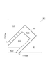
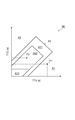
前記自車両の進行方向と当該進行方向に交差する方向とにおいて前記自車両と前記移動体とが交差する交差地点を予測し、当該交差地点に前記自車両が到達するまでの第1時間と、仮想的に設定した仮想速度により前記移動体が進行方向に交差する方向に移動したきに前記交差地点に前記移動体が到達するまでの第2時間とをそれぞれ求め、第1時間と第2時間との相対関係に基づいて、前記自車両における運転支援を行うことを特徴とする運転支援装置。 A driving support device that performs driving support to avoid a collision between the host vehicle and a moving body,
Predicting an intersection where the host vehicle and the mobile body intersect in the direction of travel of the host vehicle and the direction intersecting the direction of travel, and a first time until the host vehicle reaches the intersection, When the moving body moves in the direction intersecting the traveling direction at a virtual speed set virtually, a second time until the moving body reaches the intersection is obtained. A driving support device that performs driving support in the host vehicle on the basis of a relative relationship with the vehicle. - 前記自車両が進行方向において前記交差地点に到達するまでの前記第1時間を予測する第1時間予測手段と、
前記移動体が前記進行方向に交差する方向において前記仮想速度により前記交差地点に到達するまでの前記第2時間を予測する第2時間予測手段と、
前記第1及び第2時間予測手段によって予測された前記第1及び第2時間を予め設定されたマップに適用して、前記自車両において運転支援を実施するか否かの判断を行う運転支援判断手段と、
前記運転支援判断手段により前記自車両において運転支援を実施すると判断された場合に、前記自車両における運転支援を制御する運転支援制御手段と、
を備える、請求項1記載の運転支援装置。 First time prediction means for predicting the first time until the host vehicle reaches the intersection in the traveling direction;
Second time predicting means for predicting the second time until the moving body reaches the intersection by the virtual speed in a direction intersecting the traveling direction;
Driving support determination for determining whether to perform driving support in the host vehicle by applying the first and second times predicted by the first and second time prediction means to a preset map. Means,
Driving assistance control means for controlling driving assistance in the host vehicle when it is determined by the driving assistance judgment means to implement driving assistance in the host vehicle;
The driving support device according to claim 1, comprising: - 前記自車両の走行状態を検出する走行状態検出手段と、
前記移動体の状態を検出する移動体状態検出手段と、
前記走行状態検出手段により検出された前記自車両の状態に基づいて前記自車両の移動予測方向を算出する移動予測方向算出手段と、
前記移動体状態検出手段によって検出された前記移動体の状態から前記移動体の速度ベクトルを検出するベクトル検出手段と、
前記自車両の前記移動予測方向と前記移動体の向きとが成す角度を算出し、当該成す角度が所定角度以上であるか否かを判定する角度判定手段と、
を備え、
前記運転支援判断手段は、前記角度判定手段によって前記所定角度以上であると判定されなかった場合には前記マップを用い、前記角度判定手段によって前記所定角度以上であると判定された場合には、前記マップにおいて、検出された前記移動体の速度により当該移動体が進行方向に交差する方向に移動したときに前記交差地点に前記移動体が到達するまでの時間を第2時間とした第2マップを用いる、請求項2記載の運転支援装置。 Traveling state detecting means for detecting the traveling state of the host vehicle;
Moving body state detecting means for detecting the state of the moving body;
A predicted movement direction calculation unit that calculates a predicted movement direction of the host vehicle based on the state of the host vehicle detected by the traveling state detection unit;
Vector detecting means for detecting a velocity vector of the moving body from the state of the moving body detected by the moving body state detecting means;
An angle determination means for calculating an angle formed by the predicted movement direction of the host vehicle and the direction of the moving body, and determining whether the formed angle is a predetermined angle or more;
With
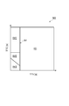
The driving support determination unit uses the map when the angle determination unit does not determine that the angle is equal to or greater than the predetermined angle, and when the angle determination unit determines that the angle is equal to or greater than the predetermined angle, In the map, when the moving body moves in the direction intersecting the traveling direction by the detected speed of the moving body, the second map is a time until the moving body reaches the intersection. The driving support device according to claim 2, wherein: - 前記マップ及び前記第2マップは、前記第1時間が縦軸で且つ前記第2時間が横軸として設定されていると共に、運転支援が不要であると判断される第1領域と、運転支援が必要であると判断される第2領域とが設定されており、
前記運転支援判断手段は、前記第1時間と前記第2時間とが交わる点が前記第2領域に存在する場合に、前記自車両において運転支援を実施すると判断する、請求項3記載の運転支援装置。 In the map and the second map, the first time is set as the vertical axis and the second time is set as the horizontal axis, and the first area where it is determined that the driving support is unnecessary, and the driving support is A second area determined to be necessary is set,
4. The driving support according to claim 3, wherein the driving support determination unit determines that the driving support is to be performed in the host vehicle when a point where the first time and the second time intersect exists in the second region. apparatus. - 前記マップ及び前記第2マップは、一つのマップに構成されている、請求項3又は4記載の運転支援装置。 The driving support device according to claim 3 or 4, wherein the map and the second map are configured as one map.
- 自車両と移動体との衝突を回避する運転支援方法であって、
前記自車両の進行方向と当該進行方向に交差する方向とにおいて前記自車両と前記移動体とが交差する交差地点を予測し、当該交差地点に前記自車両が到達するまでの第1時間と、仮想的に設定した仮想速度により前記移動体が進行方向に交差する方向に移動したきに前記交差地点に前記移動体が到達するまでの第2時間とをそれぞれ求め、第1時間と第2時間との相対関係に基づいて、自車両における運転支援を行うことを特徴とする運転支援方法。 A driving support method for avoiding a collision between a host vehicle and a moving body,
Predicting an intersection where the host vehicle and the mobile body intersect in the direction of travel of the host vehicle and the direction intersecting the direction of travel, and a first time until the host vehicle reaches the intersection, When the moving body moves in the direction intersecting the traveling direction at a virtual speed set virtually, a second time until the moving body reaches the intersection is obtained. A driving support method for performing driving support in the host vehicle based on a relative relationship with the vehicle.
Priority Applications (5)
| Application Number | Priority Date | Filing Date | Title |
|---|---|---|---|
| US14/240,808 US9196163B2 (en) | 2011-08-26 | 2011-08-26 | Driving support apparatus and driving support method |
| JP2013530891A JP5641146B2 (en) | 2011-08-26 | 2011-08-26 | Driving support device and driving support method |
| CN201180073022.5A CN103765487B (en) | 2011-08-26 | 2011-08-26 | Drive assistance device and driving assistance method |
| PCT/JP2011/069329 WO2013030906A1 (en) | 2011-08-26 | 2011-08-26 | Driving support apparatus and driving support method |
| EP11871550.7A EP2750118B1 (en) | 2011-08-26 | 2011-08-26 | Driving support apparatus and driving support method |
Applications Claiming Priority (1)
| Application Number | Priority Date | Filing Date | Title |
|---|---|---|---|
| PCT/JP2011/069329 WO2013030906A1 (en) | 2011-08-26 | 2011-08-26 | Driving support apparatus and driving support method |
Publications (1)
| Publication Number | Publication Date |
|---|---|
| WO2013030906A1 true WO2013030906A1 (en) | 2013-03-07 |
Family
ID=47755461
Family Applications (1)
| Application Number | Title | Priority Date | Filing Date |
|---|---|---|---|
| PCT/JP2011/069329 WO2013030906A1 (en) | 2011-08-26 | 2011-08-26 | Driving support apparatus and driving support method |
Country Status (5)
| Country | Link |
|---|---|
| US (1) | US9196163B2 (en) |
| EP (1) | EP2750118B1 (en) |
| JP (1) | JP5641146B2 (en) |
| CN (1) | CN103765487B (en) |
| WO (1) | WO2013030906A1 (en) |
Cited By (3)
| Publication number | Priority date | Publication date | Assignee | Title |
|---|---|---|---|---|
| CN104851320A (en) * | 2015-04-28 | 2015-08-19 | 奇瑞汽车股份有限公司 | Method and device for prompting driver |
| CN104973055A (en) * | 2014-04-14 | 2015-10-14 | 本田技研工业株式会社 | Collision possibility determination apparatus, drive assist apparatus, collision possibility determination method, and collision possibility determination program |
| JP2017105249A (en) * | 2015-12-07 | 2017-06-15 | 株式会社Subaru | Vehicle driving support control device |
Families Citing this family (21)
| Publication number | Priority date | Publication date | Assignee | Title |
|---|---|---|---|---|
| JP6049542B2 (en) * | 2013-05-31 | 2016-12-21 | 日立オートモティブシステムズ株式会社 | Vehicle control system |
| CN104050837A (en) * | 2014-06-10 | 2014-09-17 | 奇瑞汽车股份有限公司 | Driving safety prompting method and device |
| KR101628503B1 (en) * | 2014-10-27 | 2016-06-08 | 현대자동차주식회사 | Driver assistance apparatus and method for operating thereof |
| JP6462328B2 (en) | 2014-11-18 | 2019-01-30 | 日立オートモティブシステムズ株式会社 | Travel control system |
| CN104376735B (en) * | 2014-11-21 | 2016-10-12 | 中国科学院合肥物质科学研究院 | A kind of crossing, blind area vehicle driving safety early warning system and method for early warning thereof |
| JP6304223B2 (en) * | 2015-12-10 | 2018-04-04 | トヨタ自動車株式会社 | Driving assistance device |
| JP2017117344A (en) * | 2015-12-25 | 2017-06-29 | 株式会社デンソー | Travel support device |
| JP6569523B2 (en) * | 2015-12-25 | 2019-09-04 | 株式会社デンソー | Driving support device |
| JP2018018389A (en) * | 2016-07-29 | 2018-02-01 | パナソニックIpマネジメント株式会社 | Control device for automatic drive vehicle, and control program |
| JP6609237B2 (en) * | 2016-11-17 | 2019-11-20 | 株式会社デンソー | Collision determination device and collision determination method |
| KR20180058405A (en) * | 2016-11-24 | 2018-06-01 | 현대자동차주식회사 | Vehicle and method for controlling thereof |
| KR102014259B1 (en) * | 2016-11-24 | 2019-08-26 | 엘지전자 주식회사 | Vehicle control device mounted on vehicle and method for controlling the vehicle |
| US10474163B2 (en) * | 2016-11-24 | 2019-11-12 | Lg Electronics Inc. | Vehicle control device mounted on vehicle and method for controlling the vehicle |
| US10611370B2 (en) * | 2017-02-09 | 2020-04-07 | Panasonic Intellectual Property Corporation Of America | Information processing apparatus, information processing method, and non-transitory recording medium |
| EP3413083B1 (en) * | 2017-06-09 | 2020-03-11 | Veoneer Sweden AB | A vehicle system for detection of oncoming vehicles |
| EP3413082B1 (en) * | 2017-06-09 | 2020-01-01 | Veoneer Sweden AB | A vehicle system for detection of oncoming vehicles |
| KR102486179B1 (en) * | 2018-02-20 | 2023-01-10 | 현대자동차주식회사 | Vehicle, and control method for the same |
| JP7085371B2 (en) * | 2018-03-15 | 2022-06-16 | 本田技研工業株式会社 | Vehicle control devices, vehicle control methods, and programs |
| US20210293563A1 (en) * | 2018-11-06 | 2021-09-23 | Lg Electronics Inc. | Vehicular electronic device, operation method of vehicular electronic device, and system |
| US11332132B2 (en) * | 2019-08-30 | 2022-05-17 | Argo AI, LLC | Method of handling occlusions at intersections in operation of autonomous vehicle |
| US10971005B1 (en) * | 2019-12-26 | 2021-04-06 | Continental Automotive Systems, Inc. | Determining I2X traffic-participant criticality |
Citations (5)
| Publication number | Priority date | Publication date | Assignee | Title |
|---|---|---|---|---|
| JP2004164315A (en) * | 2002-11-13 | 2004-06-10 | Toyota Motor Corp | Collision alarm system for vehicle |
| JP2006256493A (en) * | 2005-03-17 | 2006-09-28 | Advics:Kk | Traveling support device for vehicle |
| JP2007257338A (en) * | 2006-03-23 | 2007-10-04 | Toyota Central Res & Dev Lab Inc | Potential risk estimation device |
| JP2009053925A (en) * | 2007-08-27 | 2009-03-12 | Toyota Motor Corp | Behavior prediction device |
| JP2010257298A (en) | 2009-04-27 | 2010-11-11 | Honda Motor Co Ltd | Travel safety device of vehicle |
Family Cites Families (6)
| Publication number | Priority date | Publication date | Assignee | Title |
|---|---|---|---|---|
| JP3653954B2 (en) * | 1997-10-23 | 2005-06-02 | トヨタ自動車株式会社 | Mobile device for mobile traffic control system, control station for mobile traffic control system, mobile traffic control system |
| US7124027B1 (en) * | 2002-07-11 | 2006-10-17 | Yazaki North America, Inc. | Vehicular collision avoidance system |
| JP2004302621A (en) | 2003-03-28 | 2004-10-28 | Calsonic Kansei Corp | Vehicle collision preventing device |
| US7729857B2 (en) * | 2005-08-18 | 2010-06-01 | Gm Global Technology Operations, Inc. | System for and method of detecting a collision and predicting a vehicle path |
| JP2010188981A (en) * | 2009-02-20 | 2010-09-02 | Fuji Heavy Ind Ltd | Driving support device of vehicle |
| US8577550B2 (en) * | 2009-10-05 | 2013-11-05 | Ford Global Technologies, Llc | System for vehicle control to mitigate intersection collisions and method of using the same |
-
2011
- 2011-08-26 US US14/240,808 patent/US9196163B2/en not_active Expired - Fee Related
- 2011-08-26 JP JP2013530891A patent/JP5641146B2/en not_active Expired - Fee Related
- 2011-08-26 WO PCT/JP2011/069329 patent/WO2013030906A1/en active Application Filing
- 2011-08-26 EP EP11871550.7A patent/EP2750118B1/en active Active
- 2011-08-26 CN CN201180073022.5A patent/CN103765487B/en not_active Expired - Fee Related
Patent Citations (5)
| Publication number | Priority date | Publication date | Assignee | Title |
|---|---|---|---|---|
| JP2004164315A (en) * | 2002-11-13 | 2004-06-10 | Toyota Motor Corp | Collision alarm system for vehicle |
| JP2006256493A (en) * | 2005-03-17 | 2006-09-28 | Advics:Kk | Traveling support device for vehicle |
| JP2007257338A (en) * | 2006-03-23 | 2007-10-04 | Toyota Central Res & Dev Lab Inc | Potential risk estimation device |
| JP2009053925A (en) * | 2007-08-27 | 2009-03-12 | Toyota Motor Corp | Behavior prediction device |
| JP2010257298A (en) | 2009-04-27 | 2010-11-11 | Honda Motor Co Ltd | Travel safety device of vehicle |
Non-Patent Citations (1)
| Title |
|---|
| See also references of EP2750118A4 |
Cited By (4)
| Publication number | Priority date | Publication date | Assignee | Title |
|---|---|---|---|---|
| CN104973055A (en) * | 2014-04-14 | 2015-10-14 | 本田技研工业株式会社 | Collision possibility determination apparatus, drive assist apparatus, collision possibility determination method, and collision possibility determination program |
| CN104973055B (en) * | 2014-04-14 | 2017-12-29 | 本田技研工业株式会社 | Collide possibility decision maker, drive assistance device, collision possibility decision method and collision possibility decision procedure |
| CN104851320A (en) * | 2015-04-28 | 2015-08-19 | 奇瑞汽车股份有限公司 | Method and device for prompting driver |
| JP2017105249A (en) * | 2015-12-07 | 2017-06-15 | 株式会社Subaru | Vehicle driving support control device |
Also Published As
| Publication number | Publication date |
|---|---|
| EP2750118A1 (en) | 2014-07-02 |
| CN103765487B (en) | 2016-03-30 |
| JPWO2013030906A1 (en) | 2015-03-23 |
| US20140288816A1 (en) | 2014-09-25 |
| EP2750118A4 (en) | 2016-04-06 |
| US9196163B2 (en) | 2015-11-24 |
| EP2750118B1 (en) | 2020-01-01 |
| CN103765487A (en) | 2014-04-30 |
| JP5641146B2 (en) | 2014-12-17 |
Similar Documents
| Publication | Publication Date | Title |
|---|---|---|
| JP5641146B2 (en) | Driving support device and driving support method | |
| JP5664790B2 (en) | Driving support device and driving support method | |
| JP5668862B2 (en) | Driving support device and driving support method | |
| JP6318864B2 (en) | Driving assistance device | |
| JP6036839B2 (en) | Driving support device and driving support method | |
| US9058247B2 (en) | Risk potential calculation apparatus | |
| JP5846106B2 (en) | Driving support device and driving support method | |
| JP2008003880A (en) | Vehicle periphery monitoring system, vehicle periphery monitoring program and method for constructing vehicle periphery monitoring system and server | |
| JP2013246768A (en) | Drive support device | |
| JP5733273B2 (en) | Driving support device and driving support method | |
| JP2013186626A (en) | Driving support device and driving support method | |
| JP2018090006A (en) | Drive support apparatus | |
| JP5915386B2 (en) | Driving support device and driving support method | |
| WO2013132621A1 (en) | Driving support device and driving support method | |
| JP2021020518A (en) | Vehicular display controller and vehicular display control method | |
| JP2013156688A (en) | Driving support device and driving support method | |
| JP2013149077A (en) | Driving support device and driving support method | |
| JP2013156687A (en) | Apparatus and method for driving assistance | |
| JP2013161232A (en) | Apparatus and method for driving assistance | |
| JP2014148291A (en) | Driving assist device and driving assist method | |
| JP2013246767A (en) | Drive support device |
Legal Events
| Date | Code | Title | Description |
|---|---|---|---|
| WWE | Wipo information: entry into national phase |
Ref document number: 201180073022.5 Country of ref document: CN |
|
| 121 | Ep: the epo has been informed by wipo that ep was designated in this application |
Ref document number: 11871550 Country of ref document: EP Kind code of ref document: A1 |
|
| ENP | Entry into the national phase |
Ref document number: 2013530891 Country of ref document: JP Kind code of ref document: A |
|
| WWE | Wipo information: entry into national phase |
Ref document number: 14240808 Country of ref document: US |
|
| NENP | Non-entry into the national phase |
Ref country code: DE |