JP6569523B2 - Driving support device - Google Patents
Driving support device Download PDFInfo
- Publication number
- JP6569523B2 JP6569523B2 JP2015254445A JP2015254445A JP6569523B2 JP 6569523 B2 JP6569523 B2 JP 6569523B2 JP 2015254445 A JP2015254445 A JP 2015254445A JP 2015254445 A JP2015254445 A JP 2015254445A JP 6569523 B2 JP6569523 B2 JP 6569523B2
- Authority
- JP
- Japan
- Prior art keywords
- collision prediction
- vehicle
- collision
- speed
- width
- Prior art date
- Legal status (The legal status is an assumption and is not a legal conclusion. Google has not performed a legal analysis and makes no representation as to the accuracy of the status listed.)
- Active
Links
- 238000001514 detection method Methods 0.000 claims description 42
- 238000013459 approach Methods 0.000 claims description 5
- 238000012937 correction Methods 0.000 description 44
- 238000000034 method Methods 0.000 description 19
- 230000008569 process Effects 0.000 description 12
- 230000008859 change Effects 0.000 description 8
- 238000003384 imaging method Methods 0.000 description 5
- 230000001133 acceleration Effects 0.000 description 4
- 230000005540 biological transmission Effects 0.000 description 3
- 230000000694 effects Effects 0.000 description 3
- 230000003111 delayed effect Effects 0.000 description 2
- 238000012545 processing Methods 0.000 description 2
- 230000004044 response Effects 0.000 description 2
- 230000003247 decreasing effect Effects 0.000 description 1
- 238000010586 diagram Methods 0.000 description 1
- 230000012447 hatching Effects 0.000 description 1
- 230000010365 information processing Effects 0.000 description 1
- 238000012986 modification Methods 0.000 description 1
- 230000004048 modification Effects 0.000 description 1
Images


Classifications
-
- B—PERFORMING OPERATIONS; TRANSPORTING
- B60—VEHICLES IN GENERAL
- B60W—CONJOINT CONTROL OF VEHICLE SUB-UNITS OF DIFFERENT TYPE OR DIFFERENT FUNCTION; CONTROL SYSTEMS SPECIALLY ADAPTED FOR HYBRID VEHICLES; ROAD VEHICLE DRIVE CONTROL SYSTEMS FOR PURPOSES NOT RELATED TO THE CONTROL OF A PARTICULAR SUB-UNIT
- B60W30/00—Purposes of road vehicle drive control systems not related to the control of a particular sub-unit, e.g. of systems using conjoint control of vehicle sub-units
- B60W30/08—Active safety systems predicting or avoiding probable or impending collision or attempting to minimise its consequences
- B60W30/095—Predicting travel path or likelihood of collision
- B60W30/0956—Predicting travel path or likelihood of collision the prediction being responsive to traffic or environmental parameters
-
- B—PERFORMING OPERATIONS; TRANSPORTING
- B60—VEHICLES IN GENERAL
- B60T—VEHICLE BRAKE CONTROL SYSTEMS OR PARTS THEREOF; BRAKE CONTROL SYSTEMS OR PARTS THEREOF, IN GENERAL; ARRANGEMENT OF BRAKING ELEMENTS ON VEHICLES IN GENERAL; PORTABLE DEVICES FOR PREVENTING UNWANTED MOVEMENT OF VEHICLES; VEHICLE MODIFICATIONS TO FACILITATE COOLING OF BRAKES
- B60T7/00—Brake-action initiating means
- B60T7/12—Brake-action initiating means for automatic initiation; for initiation not subject to will of driver or passenger
-
- B—PERFORMING OPERATIONS; TRANSPORTING
- B60—VEHICLES IN GENERAL
- B60W—CONJOINT CONTROL OF VEHICLE SUB-UNITS OF DIFFERENT TYPE OR DIFFERENT FUNCTION; CONTROL SYSTEMS SPECIALLY ADAPTED FOR HYBRID VEHICLES; ROAD VEHICLE DRIVE CONTROL SYSTEMS FOR PURPOSES NOT RELATED TO THE CONTROL OF A PARTICULAR SUB-UNIT
- B60W30/00—Purposes of road vehicle drive control systems not related to the control of a particular sub-unit, e.g. of systems using conjoint control of vehicle sub-units
- B60W30/08—Active safety systems predicting or avoiding probable or impending collision or attempting to minimise its consequences
- B60W30/095—Predicting travel path or likelihood of collision
-
- G—PHYSICS
- G08—SIGNALLING
- G08G—TRAFFIC CONTROL SYSTEMS
- G08G1/00—Traffic control systems for road vehicles
- G08G1/16—Anti-collision systems
-
- G—PHYSICS
- G08—SIGNALLING
- G08G—TRAFFIC CONTROL SYSTEMS
- G08G1/00—Traffic control systems for road vehicles
- G08G1/16—Anti-collision systems
- G08G1/166—Anti-collision systems for active traffic, e.g. moving vehicles, pedestrians, bikes
-
- B—PERFORMING OPERATIONS; TRANSPORTING
- B60—VEHICLES IN GENERAL
- B60R—VEHICLES, VEHICLE FITTINGS, OR VEHICLE PARTS, NOT OTHERWISE PROVIDED FOR
- B60R21/00—Arrangements or fittings on vehicles for protecting or preventing injuries to occupants or pedestrians in case of accidents or other traffic risks
- B60R21/34—Protecting non-occupants of a vehicle, e.g. pedestrians
-
- B—PERFORMING OPERATIONS; TRANSPORTING
- B60—VEHICLES IN GENERAL
- B60W—CONJOINT CONTROL OF VEHICLE SUB-UNITS OF DIFFERENT TYPE OR DIFFERENT FUNCTION; CONTROL SYSTEMS SPECIALLY ADAPTED FOR HYBRID VEHICLES; ROAD VEHICLE DRIVE CONTROL SYSTEMS FOR PURPOSES NOT RELATED TO THE CONTROL OF A PARTICULAR SUB-UNIT
- B60W10/00—Conjoint control of vehicle sub-units of different type or different function
- B60W10/18—Conjoint control of vehicle sub-units of different type or different function including control of braking systems
-
- B—PERFORMING OPERATIONS; TRANSPORTING
- B60—VEHICLES IN GENERAL
- B60W—CONJOINT CONTROL OF VEHICLE SUB-UNITS OF DIFFERENT TYPE OR DIFFERENT FUNCTION; CONTROL SYSTEMS SPECIALLY ADAPTED FOR HYBRID VEHICLES; ROAD VEHICLE DRIVE CONTROL SYSTEMS FOR PURPOSES NOT RELATED TO THE CONTROL OF A PARTICULAR SUB-UNIT
- B60W2420/00—Indexing codes relating to the type of sensors based on the principle of their operation
- B60W2420/40—Photo, light or radio wave sensitive means, e.g. infrared sensors
- B60W2420/403—Image sensing, e.g. optical camera
-
- B—PERFORMING OPERATIONS; TRANSPORTING
- B60—VEHICLES IN GENERAL
- B60W—CONJOINT CONTROL OF VEHICLE SUB-UNITS OF DIFFERENT TYPE OR DIFFERENT FUNCTION; CONTROL SYSTEMS SPECIALLY ADAPTED FOR HYBRID VEHICLES; ROAD VEHICLE DRIVE CONTROL SYSTEMS FOR PURPOSES NOT RELATED TO THE CONTROL OF A PARTICULAR SUB-UNIT
- B60W2420/00—Indexing codes relating to the type of sensors based on the principle of their operation
- B60W2420/40—Photo, light or radio wave sensitive means, e.g. infrared sensors
- B60W2420/408—Radar; Laser, e.g. lidar
Landscapes
- Engineering & Computer Science (AREA)
- Transportation (AREA)
- Mechanical Engineering (AREA)
- Automation & Control Theory (AREA)
- Physics & Mathematics (AREA)
- General Physics & Mathematics (AREA)
- Traffic Control Systems (AREA)
- Control Of Driving Devices And Active Controlling Of Vehicle (AREA)
- Regulating Braking Force (AREA)
Description
本発明は、車両に搭載され、車両の前方に存在する物体を検出して、車両により走行支援を実施させる走行支援装置に関する。 The present invention relates to a travel support apparatus that detects an object that is mounted on a vehicle and exists in front of the vehicle and that performs travel support by the vehicle.
近年、センサやデータ処理の高度化に伴って、車両の進路に向かって横方向から物体が進入することで生じる衝突事故を未然に回避する走行支援装置を車両に搭載することが行われつつある。この走行支援装置として、例えば、特許文献1では、物体が車両の進路に向かって横方向から接近してくる横移動速度が所定速度以上であり、かつ物体と車両との距離が所定距離以下である場合には、物体を検出するための検出領域を拡張する。この検出領域は、カメラとレーダとの両方が物体を検出できる範囲内であるため、横方向に移動する物体を高精度に検出できる。
In recent years, with the advancement of sensors and data processing, a vehicle is being equipped with a driving support device that avoids a collision accident caused by an object entering from the lateral direction toward the vehicle path. . As this driving support device, for example, in
このように、特許文献1に記載の走行支援装置では、車両の進路に向かって物体が横方向から接近してくる場合に、その物体の距離と速度に応じて検出領域を拡大することで、横方向から車両の進路に接近する物体を検出している。しかし、物体が車両に接触する事無く車両の進路を横切る場合や、車両の進路に物体が進入する前に物体の進路を車両が通り抜ける場合(上記二つの状況を、ともに「すり抜け」と呼称)にも、検出領域を拡大し、それにより不要な警報や自動制動等の走行支援を実施させるおそれがある。
Thus, in the driving assistance device described in
本発明は、上記課題を解決するためになされたものであり、その主たる目的は、すり抜けにより物体と車両とが衝突しない場合に、不要な走行支援を実施させることを抑制する事が可能な走行支援装置を提供することにある。 The present invention has been made in order to solve the above-described problems, and a main purpose of the present invention is a travel capable of suppressing unnecessary travel support when an object and a vehicle do not collide due to slipping through. It is to provide a support device.
本発明は、走行支援装置であって、車両の進行方向に対して交差する方向に移動する物体を検出する物体検出部と、前記物体検出部により検出された前記物体と前記車両とが衝突することを予測する衝突予測部と、前記衝突予測部により前記物体と前記車両とが衝突すると予測された場合に、前記車両により衝突を抑制する走行支援を実施させる支援実施部と、前記物体の速度を算出する速度算出部と、前記物体検出部により検出された前記物体の情報に基づいて、前記物体と前記車両とが衝突するまでの予測時間である衝突予測時間を算出する衝突予測時間算出部と、を備え、前記衝突予測部は、前記車両の進行方向に直交する横方向における前記車両に対する位置を表す横位置軸と、前記車両の進行方向に設定した前記衝突予測時間を表す予測時間軸とで規定される判定平面における領域として第一衝突予測領域を構築し、前記判定平面において前記第一衝突予測領域に前記物体が存在するか否かで、前記物体との衝突を予測し、前記横位置軸の方向における前記第一衝突予測領域の幅は、前記車両の幅に基づいて設定され、前記第一衝突予測領域の前記横位置は、前記速度算出部により算出される前記物体の速度と、前記衝突予測時間とに基づいて設定されることを特徴とする。 The present invention is a travel support device, in which an object detection unit that detects an object that moves in a direction that intersects the traveling direction of the vehicle, and the object detected by the object detection unit collides with the vehicle. A collision predicting unit that predicts this, a support execution unit that implements travel support that suppresses the collision by the vehicle when the collision predicting unit predicts that the object and the vehicle collide, and the speed of the object And a collision prediction time calculation unit that calculates a collision prediction time that is a prediction time until the object and the vehicle collide based on information on the object detected by the object detection unit. The collision prediction unit represents a horizontal position axis representing a position with respect to the vehicle in a lateral direction orthogonal to the traveling direction of the vehicle, and the predicted collision time set in the traveling direction of the vehicle. A first collision prediction area is constructed as an area on the determination plane defined by the prediction time axis, and a collision with the object is predicted based on whether or not the object exists in the first collision prediction area on the determination plane. The width of the first collision prediction area in the direction of the lateral position axis is set based on the width of the vehicle, and the lateral position of the first collision prediction area is calculated by the speed calculation unit. It is set based on the speed of the object and the predicted collision time.
車両の進行方向に直交する横方向における物体と車両との相対位置である横位置と、衝突予測時間とから第一衝突予測領域を構築し、その第一衝突予測領域内に物体が存在するか否かで物体との衝突が衝突予測部により予測される。この第一衝突予測領域について、その横位置方向の幅は車両の幅に基づいて設定される。これにより、横位置方向の幅を超える位置に存在する物体は、車両と衝突するおそれが少ないと判定することができる。また、物体の速度と衝突予測時間とに基づいて第一衝突予測領域の横位置が設定されることで、その速度の物体が車両と衝突する可能性が高いのか否かを精度高く予測することができる。このため、第一衝突予測領域から物体が外れることで、物体と車両とが衝突することなくすり抜けると判定されるため、不要な走行支援を実施させることを抑制する事が可能となる。 Whether the first collision prediction area is constructed from the lateral position that is the relative position of the object and the vehicle in the lateral direction orthogonal to the traveling direction of the vehicle, and the collision prediction time, and whether the object exists in the first collision prediction area The collision prediction unit predicts the collision with the object. About this 1st collision prediction area | region, the width | variety of the horizontal position direction is set based on the width | variety of a vehicle. Thereby, it can be determined that an object present at a position exceeding the width in the lateral position direction is less likely to collide with the vehicle. In addition, by setting the lateral position of the first collision prediction area based on the speed of the object and the predicted collision time, it is possible to accurately predict whether or not the object at that speed is likely to collide with the vehicle. Can do. For this reason, it is determined that the object slips out of the first collision prediction area without causing the object and the vehicle to collide with each other, so that it is possible to suppress unnecessary travel support.
本実施形態に係る走行支援装置は、車両(自車両)に搭載され、自車両の進行方向前方等の周囲に存在する物体を検知し、走行支援制御を実施する。この走行支援制御は、物体との衝突を回避すべく、若しくは衝突被害を軽減すべく制御を行うPCSシステム(Pre−crash safety system)として機能する。 The travel support apparatus according to the present embodiment is mounted on a vehicle (own vehicle), detects an object existing around the front of the travel direction of the own vehicle, and performs travel support control. This driving support control functions as a PCS system (Pre-crush safety system) that performs control to avoid collision with an object or reduce collision damage.
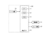
図1において、走行支援装置100は、検出ECU10とレーダ装置21とから構成されている。
In FIG. 1, the
レーダ装置21は、例えば、ミリ波帯の高周波信号を送信波とする公知のミリ波レーダであり、自車両の前端部に設けられ、所定の検知角に入る領域を物体を検知可能な検知範囲とし、検知範囲内の物体の位置を検出する。具体的には、所定周期で探査波を送信し、複数のアンテナにより反射波を受信する。この探査波の送信時刻と反射波の受信時刻とにより、物体との距離を算出する。また、物体に反射された反射波の、ドップラー効果により変化した周波数により、相対速度(詳しくは車両の進行方向における相対速度)を算出する。加えて、複数のアンテナが受信した反射波の位相差により、物体の方位を算出する。なお、物体の位置及び方位が算出できれば、その物体の、自車両に対する相対位置(横位置)を特定することができる。よって、レーダ装置21は、物体検出部及び速度算出部に該当する。レーダ装置21は、所定周期毎に、探査波の送信、反射波の受信、反射位置及び相対速度の算出を行い、算出した反射位置と相対速度とを検出ECU10に送信する。
The
検出ECU10には、レーダ装置21が接続されている。検出ECU10は、CPU11、RAM12、ROM13、I/O等を備えたコンピュータである。この検出ECU10は、CPU11が、ROM13にインストールされているプログラムを実施することでこれら各機能を実現する。本実施形態において、ROM13にインストールされているプログラムは、レーダ装置21が検出した物体の情報(算出した位置と相対速度など)に基づいて、自車両の前方に存在する物体を検出して規定の走行支援処理を実施させるための制御プログラムである。この検出ECU10は、速度算出部、衝突予測部、支援実施部、及び衝突予測時間算出部に該当する。
A
本実施形態において、走行支援処理とは、自車両と衝突するおそれのある物体が存在することをドライバに報知する警報処理と自車両を制動させる制動処理に該当する。したがって、自車両には、検出ECU10からの制御指令により駆動する安全装置として、警報装置31及びブレーキ装置32が備えられている。
In the present embodiment, the driving support process corresponds to an alarm process for notifying the driver that there is an object that may collide with the host vehicle and a braking process for braking the host vehicle. Therefore, the host vehicle is provided with an
警報装置31は、自車両の車室内に設置されたスピーカやディスプレイである。検出ECU10が、後述の衝突予測時間(TTC:Time−to−collision)が第一所定時間よりも縮まり、物体に自車両が衝突する可能性が高まったと判定した場合には、その検出ECU10からの制御指令により、警報装置31は警報音や警報メッセージ等を出力してドライバに衝突の危険を報知する。このため、警報装置31は報知部に該当する。
The
ブレーキ装置32は、自車両を制動する制動装置である。検出ECU10が、後述の衝突予測時間が第一所定時間よりも短く設定された第二所定時間よりも縮まり、物体に自車両が衝突する可能性が高まったと判定した場合には、その検出ECU10からの制御指令により、ブレーキ装置32が作動する。具体的には、ドライバによるブレーキ操作に対する制動力をより強くしたり(ブレーキアシスト機能)、ドライバによりブレーキ操作が行われてなければ自動制動を行ったりする(自動ブレーキ機能)。よって、ブレーキ装置32は自動制動部に該当する。
The brake device 32 is a braking device that brakes the host vehicle. When the
ところで、検出ECU10は、自車両とレーダ装置21が検出した物体とが衝突するまでの時間である衝突予測時間を算出する。具体的には、自車両と物体との相対距離及び相対速度に基づいて、衝突予測時間を算出する。この衝突予測時間が縦軸で、自車両の進行方向に直交する横方向における自車両に対する位置を表す横位置が横軸で規定される判定平面において、レーダ装置21が物体を検出可能な領域としてレーダ検出領域を、図2のように構築する。
By the way, the
ただし、レーダ検出領域に存在する物体全てが自車両と衝突するおそれのある物体である訳ではない。したがって、レーダ検出領域を更に限定するように設定された衝突予測領域内に収まる物体を自車両と衝突するおそれがあるとして認識する。判定平面において、物体は横位置と衝突予測時間とで点(現在位置)として特定される。従来の検出ECUでは、矩形の枠で示すように、横位置と衝突予測時間それぞれに閾値を設けることで構築された衝突予測領域内に収まる物体を自車両と衝突するおそれがあるとして判定していた。しかし、ハッチング領域で示すように、自車両と衝突する可能性が高い領域は従来の検出ECUにより設定される衝突予測領域よりも狭い範囲である。このため、物体が自車両に接触する事無く自車両の進路を横切る場合や、自車両の進路に物体が進入する前に物体の進路を自車両が通り抜ける場合でも、その衝突予測領域内に物体が収まり、それにより物体と自車両とが衝突しないにも関わらず走行支援処理を実施させるおそれがある。 However, not all objects existing in the radar detection area are objects that may collide with the host vehicle. Therefore, an object that falls within the collision prediction area set so as to further limit the radar detection area is recognized as being likely to collide with the host vehicle. In the determination plane, the object is specified as a point (current position) by the lateral position and the predicted collision time. In the conventional detection ECU, as indicated by a rectangular frame, it is determined that there is a possibility that an object that falls within the collision prediction area constructed by providing threshold values for the lateral position and the collision prediction time may collide with the host vehicle. It was. However, as indicated by the hatching area, the area that is highly likely to collide with the host vehicle is a narrower area than the collision prediction area set by the conventional detection ECU. For this reason, even if the object crosses the course of the own vehicle without contacting the own vehicle, or even if the own vehicle passes through the course of the object before the object enters the course of the own vehicle, the object is within the collision prediction area. This may cause the driving support process to be executed even though the object and the host vehicle do not collide.
よって、本実施形態における検出ECU10では、衝突予測領域の横位置を、レーダ検出領域内に存在する物体の速度と衝突予測時間とに基づいて設定する。また、警報装置31による報知処理と、ブレーキ装置32による自動制動制御とでは、その制御を実施させるか否かの判定条件が必ずしも一致しないことを考慮し、第一衝突予測領域及び第三衝突予測領域を構築する。
Therefore, the
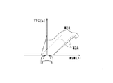
具体的には、図3に記載されるように衝突予測領域の横軸方向における幅を自車両の幅に、そして、縦軸方向における範囲を0から第二所定時間までと設定した第一衝突予測領域を構築する。このとき、時刻tにおける物体の横位置軸方向(右方向を正とする)の速度をV(t)、衝突予測時間をTTCとすると、第一衝突予測領域の右端Xr(t)及び左端Xl(t)は、(1)式及び(2)式により表される。なお、式中に記載の自車両前方右端Xrは、自車両の中心から車幅の半分の幅だけ横位置軸方向に右側の点の座標位置であり、自車両前方左端Xlは、自車両の中心から車幅の半分の幅だけ横位置軸方向に左側の点の座標位置である。構築された第一衝突予測領域内に存在する物体は自車両と衝突する可能性があるとして、ブレーキ装置32に自動制動制御を実施させる。 Specifically, as shown in FIG. 3, the first collision in which the width in the horizontal axis direction of the collision prediction area is set to the width of the host vehicle and the range in the vertical axis direction is set from 0 to a second predetermined time. Build a prediction area. At this time, assuming that the velocity of the object in the horizontal position axis direction (right direction is positive) at time t is V (t) and the collision prediction time is TTC, the right end Xr (t) and the left end Xl of the first collision prediction region. (T) is expressed by equations (1) and (2). The right front end Xr of the host vehicle described in the equation is the coordinate position of a point on the right side in the horizontal axis direction by a width that is half the width of the vehicle from the center of the host vehicle. It is the coordinate position of the point on the left side in the horizontal position axis direction by half the width of the vehicle from the center. The brake device 32 is caused to perform automatic braking control on the assumption that an object that exists in the constructed first collision prediction area may collide with the host vehicle.
Xr(t)=Xr−V(t)×TTC…(1) Xr (t) = Xr−V (t) × TTC (1)
Xl(t)=Xl−V(t)×TTC…(2) Xl (t) = Xl−V (t) × TTC (2)
また、横軸の方向における第一衝突予測領域の幅(第一衝突予測領域の横幅)を両側に所定幅Lずつ拡大し、縦軸方向における範囲を0から第一所定時間までと設定した第三衝突予測領域を構築する。第一衝突予測領域の横幅を両側に所定幅Lずつ拡大することについて、具体的には、(3)式に記載されるように自車両前方右端Xrに所定幅Lを加算するとともに、(4)式に記載されるように自車両前方左端Xlに所定幅Lを引くことで、第一衝突予測領域の横幅を拡大補正する。この第三衝突予測領域内に存在する物体は、自車両と衝突する可能性が高い、あるいは自車両又は物体の加減速により自車両と衝突する軌跡に変わる可能性があるとして、警報装置31による報知処理の判定対象とする。
In addition, the width of the first collision prediction area in the horizontal axis direction (horizontal width of the first collision prediction area) is increased by a predetermined width L on both sides, and the range in the vertical axis direction is set from 0 to the first predetermined time. Build three collision prediction areas. More specifically, the predetermined width L is increased on both sides by the predetermined width L, and the predetermined width L is added to the front right end Xr of the host vehicle as described in the equation (3), and (4 As shown in the equation, the lateral width of the first collision prediction region is enlarged and corrected by drawing a predetermined width L at the front left end Xl of the host vehicle. The
Xr2(t)=Xr+L−V(t)×TTC…(3) Xr2 (t) = Xr + LV (t) × TTC (3)
Xl2(t)=Xl−L−V(t)×TTC…(4) Xl2 (t) = Xl-LV (t) × TTC (4)
本実施形態では、検出ECU10により後述する図4に記載の走行支援制御を実施する。図4に示す走行支援制御は、検出ECU10が電源オンしている期間中に検出ECU10によって所定周期で繰り返し実施される。
In the present embodiment, the driving assistance control shown in FIG. The driving support control shown in FIG. 4 is repeatedly performed at a predetermined cycle by the
まずステップS100にて、レーダ装置21によりレーダ検出領域に存在する物体を検出させる。そして、レーダ装置21に物体の相対位置と相対距離、そして相対速度を算出させ、それらの情報を送信させる。このとき、物体の相対位置とは、自車両に対する物体の位置及び方位に基づいて特定されるものであり、判定平面における物体の横位置に相当する。また、相対距離とは、相対位置に基づいて算出される自車両と物体との距離に相当する。ステップS110では、レーダ装置21から取得した物体の相対速度と相対距離とから物体の衝突予測時間を算出する。ステップS120では、ステップS100及びステップS110にて取得した物体の情報に基づいて、レーダ検出領域内に第一衝突予測領域及び第三衝突予測領域を構築する。
First, in step S100, the
次にステップS130にて、ステップS120で構築した二つの衝突予測領域の内、第三衝突予測領域内に物体が存在するか否かを判定する。具体的には、物体の現在位置(横位置,衝突予測時間)が第三衝突予測領域内に収まる場合に、第三衝突予測領域内に物体が存在すると判定する。第三衝突予測領域内に物体が存在しないと判定した場合には(S130:NO)、本制御を終了する。第三衝突予測領域内に物体が存在すると判定した場合には(S130:YES)、ステップS140に進み、警報装置31による報知処理を実施させる。
Next, in step S130, it is determined whether or not an object exists in the third collision prediction area among the two collision prediction areas constructed in step S120. Specifically, when the current position of the object (lateral position, collision prediction time) is within the third collision prediction area, it is determined that the object exists in the third collision prediction area. If it is determined that there is no object in the third collision prediction area (S130: NO), this control is terminated. When it is determined that an object exists in the third collision prediction area (S130: YES), the process proceeds to step S140, and a notification process by the
ステップS150では、第一衝突予測領域内に物体が存在するか否かを判定する。第一衝突予測領域内に物体が存在しないと判定した場合には(S150:NO)、本制御を終了する。第一衝突予測領域内に物体が存在すると判定した場合には(S150:YES)、ステップS160に進み、ブレーキ装置32による自動制動制御を実施させ、本制御を終了する。 In step S150, it is determined whether an object exists in the first collision prediction area. If it is determined that there is no object in the first collision prediction area (S150: NO), this control is terminated. When it is determined that an object is present in the first collision prediction area (S150: YES), the process proceeds to step S160, the automatic braking control by the brake device 32 is performed, and this control is terminated.
上記構成により、本実施形態は、以下の効果を奏する。 With this configuration, the present embodiment has the following effects.
・第一衝突予測領域について、その横位置方向の幅は自車両の幅に基づいて設定される。これにより、横位置方向の幅を超える位置に存在する物体は、自車両と衝突する可能性が低いと判定することができる。また、物体の速度と衝突予測時間とに基づいて第一衝突予測領域の横位置が設定されることで、その速度で接近してくる物体は自車両と衝突する可能性が高いのか否かを精度高く予測することができる。よって、第一衝突予測領域から物体が外れることで、物体と自車両とが衝突することなくすり抜けると判定されるため、警報装置31やブレーキ装置32による制御の誤実施を抑制する事が可能となる。
-About the 1st collision prediction area | region, the width | variety of the horizontal position direction is set based on the width | variety of the own vehicle. Thereby, it can be determined that an object present at a position exceeding the width in the lateral position direction is unlikely to collide with the host vehicle. Also, by setting the lateral position of the first collision prediction area based on the speed of the object and the predicted collision time, it is determined whether or not an object approaching at that speed is likely to collide with the host vehicle. Predict with high accuracy. Therefore, since it is determined that the object and the own vehicle pass through without the object moving from the first collision prediction area, it is possible to suppress erroneous execution of control by the
・第一衝突予測領域の横位置が、(1)式及び(2)式に記載されるように物体の速度を傾きとする直線で設定される。したがって、判定平面において、(1)式により求められる第一衝突予測領域の右端Xr(t)の仮想線と、(2)式により求められる第一衝突予測領域の左端Xl(t)の仮想線と、をひくことができる。これらの仮想線は、その速度で走行する物体が自車両に衝突する場合の境界線であるため、これらの仮想線に基づいて第一衝突予測領域を構築することで、自車両と衝突することなくすり抜ける物体を第一衝突予測領域外とすることが可能となる。また、第一衝突予測領域の縦軸方向における範囲が0から第二所定時間までに設定される。これにより、第一衝突予測領域内に存在する物体は、自車両と衝突する可能性が高いとして、ブレーキ装置32に自動制動制御を実施させることで、物体と自車両との衝突を未然に回避することが可能となる。 The lateral position of the first collision prediction area is set as a straight line with the velocity of the object as an inclination as described in the equations (1) and (2). Therefore, on the determination plane, the imaginary line at the right end Xr (t) of the first collision prediction area obtained by the expression (1) and the imaginary line at the left end Xl (t) of the first collision prediction area obtained by the expression (2). And can be pulled. Since these virtual lines are boundaries when an object traveling at that speed collides with the host vehicle, the first collision prediction area is constructed based on these virtual lines to collide with the host vehicle. It is possible to make an object that slips out of the first collision prediction area. Further, the range in the vertical axis direction of the first collision prediction area is set from 0 to the second predetermined time. As a result, it is assumed that an object existing in the first collision prediction area is likely to collide with the own vehicle, and the automatic braking control is performed by the brake device 32, thereby avoiding the collision between the object and the own vehicle. It becomes possible to do.
・第一衝突予測領域の横幅が両側に所定幅Lずつ拡大され、縦軸方向における範囲が0から第一所定時間までと設定される第三衝突予測領域が構築される。これにより、自車両と衝突する可能性が高い、あるいは自車両又は物体の加減速により自車両と衝突する軌跡に変わる可能性がある物体を、警報装置31による報知処理の実施対象とすることができ、その物体との衝突に備え、ドライバに車両の減速運転を促すことができる。
The horizontal width of the first collision prediction area is enlarged by a predetermined width L on both sides, and a third collision prediction area is set in which the range in the vertical axis direction is set from 0 to the first predetermined time. As a result, an object that has a high possibility of colliding with the host vehicle or that may change to a track that collides with the host vehicle due to acceleration or deceleration of the host vehicle or the object may be set as an execution target of the notification process by the
上記実施形態を、以下のように変更して実施することもできる。 The above embodiment can also be implemented with the following modifications.
・上記実施形態では、物体が第一衝突予測領域内に存在する場合にブレーキ装置32による自動制動制御を実施させ、物体が第三衝突予測領域内に存在する場合に警報装置31による報知処理を実施させていた。このことについて、物体との衝突を抑制するための手段は警報装置31及びブレーキ装置32に限らない。例えば、ブレーキ装置32による自動制動制御に代わって、ハンドル制御部を設け、第一衝突予測領域内に物体が存在する場合に、物体との衝突を避けるようにハンドルを自動制御してもよい。この場合、第一衝突予測領域の縦軸方向の範囲を構成する第二所定時間を、第三所定時間に変更する。この第三所定時間は、例えばハンドルの自動制御による物体との衝突回避を安全に実施するために必要な時間として設定される。
In the above embodiment, automatic braking control by the brake device 32 is performed when the object is in the first collision prediction area, and notification processing by the
・上記実施形態では、判定平面において、第一衝突予測領域及び第三衝突予測領域を構築し、それらの衝突予測領域内に存在する物体について走行支援の実施の是非を判定していた。このことについて、必ずしも第三衝突予測領域を構築する必要はない。第三衝突予測領域を構築しない場合には、第一衝突予測領域の縦軸方向の範囲を第一所定時間まで拡大する。そして、第一衝突予測領域のうち衝突予測時間が第二所定時間から第一所定時間までの範囲内に物体が進入した場合に、警報装置31による報知処理を実施させる。そして、第一衝突予測領域のうち衝突予測時間が第二所定時間よりも短い範囲内に物体が進入した場合に、ブレーキ装置32による自動制動制御を実施させる。
In the above embodiment, the first collision prediction area and the third collision prediction area are constructed on the determination plane, and whether or not the driving assistance is performed is determined for objects existing in the collision prediction area. In this regard, it is not always necessary to construct a third collision prediction area. When the third collision prediction area is not constructed, the range of the first collision prediction area in the vertical axis direction is expanded to the first predetermined time. And when an object approachs in the range from the 2nd predetermined time to the 1st predetermined time among the 1st collision prediction fields, the
・上記実施形態では、第一衝突予測領域内に物体が存在すると判定した場合に、ブレーキ装置32による自動制動制御を実施させ、物体が第一衝突予測領域から外れると判定した場合は、自車両と衝突する事無くすり抜けるとして、ブレーキ装置32による自動制動制御を実施させなかった。このことについて、第一衝突予測領域から物体が外れすり抜けることが予測された場合でも、衝突予測時間が小さい範囲では、物体又は自車両が加減速することで物体と自車両とが衝突する軌跡に変更された場合に、自動制動制御が遅れる危険性がある。この危険性を考慮し、図5に記載されるように、判定平面における縦軸方向の範囲を0から第四所定時間までと設定し、横位置が車両の幅に基づく幅よりも内側となる範囲に第二衝突予測領域を構築する。なお、第四所定時間は、第二所定時間よりも短く設定する。したがって、この第二衝突予測領域内に進入する物体も、自車両と衝突する可能性が高いとして、ブレーキ装置32による自動制動制御を実施させる。これにより、ブレーキ装置32による自動制動制御が遅れることを抑制することができ、ドライバが不安を感じることを抑制することが可能となる。 In the above embodiment, when it is determined that an object is present in the first collision prediction area, automatic braking control by the brake device 32 is performed, and when it is determined that the object is out of the first collision prediction area, The automatic braking control by the brake device 32 was not performed because the vehicle slipped without colliding with the brake device 32. In this regard, even if it is predicted that the object will slip out of the first collision prediction region, the object or the host vehicle will accelerate or decelerate in the range where the collision prediction time is short, and the object and the host vehicle will collide with each other. If changed, there is a risk that the automatic braking control will be delayed. Considering this risk, as shown in FIG. 5, the range in the vertical axis direction on the determination plane is set from 0 to the fourth predetermined time, and the lateral position is inside the width based on the width of the vehicle. Build a second collision prediction area in the range. The fourth predetermined time is set shorter than the second predetermined time. Therefore, it is assumed that an object entering the second collision prediction area is likely to collide with the host vehicle, and the automatic braking control by the brake device 32 is performed. Thereby, it can suppress that the automatic braking control by the brake device 32 is delayed, and the driver can be prevented from feeling uneasy.
[別例1]上記実施形態では、レーダ装置21が物体の検出を実施していた。このことについて、レーダ装置21に限る必要はなく、例えば、撮像装置が物体を検出してもよい。撮像装置は、例えばCCDカメラ、CMOSイメージセンサ、近赤外線カメラ等を用いた単眼カメラやステレオカメラ等が含まれる。この場合でも、撮像装置が撮影された画像に基づいて物体の位置情報や相対速度を算出することができるため、かかる構成によっても、上記実施形態と同様の作用・効果が奏される。
[Other Example 1] In the above embodiment, the
ただし、撮像装置により撮影された画像から物体の速度を検出する場合には、物体が自車両近くに存在することで撮影された画像の多くを物体が占めることになり、算出される物体の速度が小さくなる方向に誤差が生じるおそれがある。この場合、本来は第一衝突予測領域内に物体が含まれているはずが、物体の速度に誤差が生じることで第一衝突予測領域内に物体が含まれないと判定される事態が起こりうる。 However, when detecting the speed of an object from an image captured by an imaging device, the object occupies most of the captured image because the object exists near the vehicle, and the calculated object speed There is a risk that an error will occur in the direction of decreasing. In this case, an object should originally be included in the first collision prediction area, but it may be determined that an object is not included in the first collision prediction area due to an error in the speed of the object. .
よって、自車両と物体との相対距離が第一所定距離よりも短い場合には、図6に記載されるように、衝突予測領域を横方向へ広げるように、第一衝突予測領域の右端Xr(t)の直線の傾きが大きく、そして第一衝突予測領域の左端Xl(t)の直線の傾きが小さくなるように補正する。具体的には、(5)式に記載されるように、物体の速度及び衝突予測時間の積と、1に第一補正値αを加えた値と、を掛けることで第一衝突予測領域の右端Xr(t)の直線の傾きを補正する。また、(6)式に記載されるように、物体の速度及び衝突予測時間の積と、1から第一補正値αを引くことで算出される値と、を掛けることで第一衝突予測領域の左端Xl(t)の直線の傾きを補正する。第一補正値αは、図7(a)に記載されるように、相対距離が第一所定距離よりも長い場合には0であり、第一所定距離よりも短くなるほど値が0よりも大きくなる傾向を持つ。これにより、撮像装置により撮影された画像を用いて算出した物体の速度に誤差が生じた場合でも、第一衝突予測領域内に物体を収めることができる。 Therefore, when the relative distance between the host vehicle and the object is shorter than the first predetermined distance, as shown in FIG. 6, the right end Xr of the first collision prediction area is expanded so as to expand the collision prediction area in the lateral direction. Correction is performed so that the slope of the straight line (t) is large and the slope of the straight line at the left end Xl (t) of the first collision prediction region is small. Specifically, as described in the equation (5), the product of the speed of the object and the collision prediction time is multiplied by the value obtained by adding 1 to the first correction value α, thereby The inclination of the straight line at the right end Xr (t) is corrected. Further, as described in the equation (6), the first collision prediction region is obtained by multiplying the product of the object speed and the collision prediction time by a value calculated by subtracting the first correction value α from 1. The slope of the straight line at the left end Xl (t) is corrected. As shown in FIG. 7A, the first correction value α is 0 when the relative distance is longer than the first predetermined distance, and the value is larger than 0 as the relative distance becomes shorter. Have a tendency to become. Thereby, even when an error occurs in the velocity of the object calculated using the image captured by the imaging device, the object can be accommodated in the first collision prediction region.
Xr(t)=Xr−V(t)×TTC×(1+α)…(5) Xr (t) = Xr−V (t) × TTC × (1 + α) (5)
Xl(t)=Xl−V(t)×TTC×(1−α)…(6) Xl (t) = Xl−V (t) × TTC × (1−α) (6)
別例1では、第一衝突予測領域の右端Xr(t)の直線の傾きと第一衝突予測領域の左端Xl(t)の直線の傾きとを、それぞれ補正していた。このことについて、必ずしも両方の直線の傾きを、第一補正値αを用いて補正する必要はない。例えば、第一衝突予測領域の右端Xr(t)の直線の傾きを補正する際には第一補正値αを用いて、第一衝突予測領域を横方向へ広がるように補正する。その一方で、第一衝突予測領域の左端Xl(t)の直線の傾きは補正しなくてもよいし、第一補正値αとは異なる値を用いて第一衝突予測領域の左端Xl(t)の直線の傾きを補正してもよい。 In another example 1, the inclination of the straight line at the right end Xr (t) of the first collision prediction area and the inclination of the straight line at the left end Xl (t) of the first collision prediction area are corrected. In this regard, it is not always necessary to correct the slopes of both straight lines using the first correction value α. For example, when correcting the slope of the straight line at the right end Xr (t) of the first collision prediction area, the first correction prediction area α is used to correct the first collision prediction area so as to expand in the lateral direction. On the other hand, the slope of the straight line at the left end Xl (t) of the first collision prediction area does not have to be corrected, and a value different from the first correction value α is used to set the left end Xl (t of the first collision prediction area. ) May be corrected.
本別例について、第一衝突予測領域の補正方法を記載したが、上記補正方法を第三衝突予測領域に適用してもよい。 Although the correction method for the first collision prediction area has been described for this example, the above correction method may be applied to the third collision prediction area.
[別例2]上記実施形態では、第一衝突予測領域の横幅を両側に所定幅Lずつ拡大した幅を第三衝突予測領域の横軸方向における幅と設定していた。このことについて、第三衝突予測領域のうち衝突予測時間が第五所定時間よりも大きい範囲では、図8に記載されるように、第三衝突予測領域の右端Xr2(t)の直線の傾きが小さくなるように、そして第三衝突予測領域の左端Xl2(t)の直線の傾きが大きくなるように補正することで、第三衝突予測領域の横軸方向における幅を狭める。なお、第五所定時間は第二所定時間よりも大きく第一所定時間よりも小さく設定される。具体的には、(7)式に記載されるように、物体の速度及び衝突予測時間の積と、1から第二補正値βを引くことで算出される値と、を掛けることで第三衝突予測領域の右端Xr2(t)の直線の傾きを補正する。また、(8)式に記載されるように、物体の速度及び衝突予測時間の積と、1に第二補正値βを足すことで算出される値と、を掛けることで第三衝突予測領域の左端Xl2(t)の直線の傾きを補正する。第二補正値βは、図7(b)に記載されるように衝突予測時間が第五所定時間よりも小さい場合には0であり、第五所定時間よりも大きくなるほど値が0よりも大きくなる傾向を持つ。 [Another Example 2] In the above embodiment, the width of the first collision prediction area expanded by the predetermined width L on both sides is set as the width in the horizontal axis direction of the third collision prediction area. In this regard, in the third collision prediction area, in the range where the collision prediction time is longer than the fifth predetermined time, the slope of the straight line at the right end Xr2 (t) of the third collision prediction area is as shown in FIG. The width in the horizontal axis direction of the third collision prediction region is narrowed by making the correction so that the slope of the straight line at the left end Xl2 (t) of the third collision prediction region becomes large. The fifth predetermined time is set larger than the second predetermined time and smaller than the first predetermined time. Specifically, as described in Equation (7), the product of the speed of the object and the predicted collision time is multiplied by a value calculated by subtracting the second correction value β from 1 to obtain the third value. The slope of the straight line at the right end Xr2 (t) of the collision prediction area is corrected. Further, as described in the equation (8), the third collision prediction region is obtained by multiplying the product of the object speed and the collision prediction time by a value calculated by adding 1 to the second correction value β. The slope of the straight line at the left end Xl2 (t) is corrected. As shown in FIG. 7B, the second correction value β is 0 when the predicted collision time is shorter than the fifth predetermined time, and the value is larger than 0 as it becomes longer than the fifth predetermined time. Have a tendency to become.
Xr2(t)=Xr−V(t)×TTC×(1−β)…(7) Xr2 (t) = Xr−V (t) × TTC × (1-β) (7)
Xl2(t)=Xl−V(t)×TTC×(1+β)…(8) Xl2 (t) = Xl−V (t) × TTC × (1 + β) (8)
衝突予測時間が第五所定時間よりも大きい範囲にて検出される物体は、自車両と衝突するまでに時間があり、物体又は自車両が今後加減速することが予測される。したがって、現在は、物体と自車両とが衝突する軌跡であっても、今後物体と自車両とが衝突しない軌跡に変化する可能性がある。したがって、第三衝突予測領域の横軸方向における幅を狭めるように、(7)式及び(8)式に準じてそれぞれの直線の傾きが補正されることで、自車両と衝突する可能性が特に高い物体のみが検出される。これにより、物体又は自車両の加減速で第三衝突予測領域からすぐに外れる物体について走行支援の実施判定を行わずにすみ、ひいては走行支援制御の実施頻度を低減する事が出来る。 An object detected in a range where the predicted collision time is longer than the fifth predetermined time has time until it collides with the own vehicle, and it is predicted that the object or the own vehicle will accelerate or decelerate in the future. Therefore, even if the trajectory is that the object collides with the host vehicle, the trajectory may change to a trajectory in which the object and the host vehicle do not collide in the future. Therefore, there is a possibility that the vehicle collides with the host vehicle by correcting the inclination of each straight line according to the equations (7) and (8) so as to narrow the width of the third collision prediction region in the horizontal axis direction. Only particularly high objects are detected. Accordingly, it is not necessary to perform execution support execution determination for an object or an object that immediately deviates from the third collision prediction region due to acceleration / deceleration of the host vehicle, and thus the execution frequency of the drive support control can be reduced.
別例2では、第三衝突予測領域の右端Xr2(t)の直線の傾きと第三衝突予測領域の左端Xl2(t)の直線の傾きとを、それぞれ補正していた。このことについて、必ずしも両方の直線の傾きを、第二補正値βを用いて補正する必要はない。例えば、第三衝突予測領域の右端Xr2(t)の直線の傾きを補正する際には第二補正値βを用いて、第三衝突予測領域の横軸方向における幅を狭めるように補正する。その一方で、第三衝突予測領域の左端Xl2(t)の直線の傾きは補正しなくてもよいし、第二補正値βとは異なる値を用いて第三衝突予測領域の左端Xl2(t)の直線の傾きを補正してもよい。 In another example 2, the inclination of the straight line at the right end Xr2 (t) of the third collision prediction area and the inclination of the straight line at the left end Xl2 (t) of the third collision prediction area are corrected. In this regard, it is not always necessary to correct the slopes of both straight lines using the second correction value β. For example, when the inclination of the straight line at the right end Xr2 (t) of the third collision prediction area is corrected, the second correction value β is used to correct the width of the third collision prediction area in the horizontal axis direction. On the other hand, it is not necessary to correct the slope of the straight line at the left end Xl2 (t) of the third collision prediction region, and the left end Xl2 (t ) May be corrected.
別例2について、第三衝突予測領域の補正方法を記載したが、上記補正方法を第一衝突予測領域に適用してもよい。 Although the correction method for the third collision prediction area has been described for the second example, the above correction method may be applied to the first collision prediction area.
[別例3]上記実施形態では、第一衝突予測領域の横軸方向における幅を自車両の幅に設定していた。このことについて、判定平面における横位置軸方向の物体の速度が第一所定速度よりも低い場合、特に物体が歩行者である場合には、その物体の速度が頻繁に加減速を実施することが想定される。この場合、第一衝突予測領域から物体が外れすり抜けることが予測された場合でも、物体の不慮の加減速により物体と自車両とが将来的に衝突する軌跡に変わることで、衝突予測時間が第二所定時間よりも短い状態で第一衝突予測領域内に物体が進入するおそれがある。このような状況に備え、物体の速度が第一所定速度よりも低い場合には、図9に記載されるように、第一衝突予測領域の横幅を両方向に拡大するように補正する。具体的には、(9)式及び(10)式に記載されるように、自車両前方右端Xr及び自車両前方左端Xlのそれぞれに第一補正係数γを掛けることで、第一衝突予測領域の横幅を補正する。第一補正係数γは、図10(a)に記載されるように、物体の速度の絶対値が第一所定速度よりも高い場合には1であり、第一所定速度よりも低くなるほど値が1よりも大きくなる傾向を持つ。これにより、物体の挙動に変化が生じやすい状況においても、物体と自車両との衝突を精度高く予測することが可能となる。 [Other Example 3] In the above embodiment, the width of the first collision prediction region in the horizontal axis direction is set to the width of the host vehicle. In this regard, when the speed of the object in the lateral axis direction on the determination plane is lower than the first predetermined speed, particularly when the object is a pedestrian, the speed of the object may be frequently accelerated / decelerated. is assumed. In this case, even when it is predicted that the object will slip out of the first collision prediction area, the collision prediction time will be increased by changing to a trajectory in which the object and the vehicle will collide in the future due to accidental acceleration / deceleration of the object. There is a possibility that the object enters the first collision prediction area in a state shorter than two predetermined times. In preparation for such a situation, when the speed of the object is lower than the first predetermined speed, correction is made so that the lateral width of the first collision prediction area is expanded in both directions, as shown in FIG. Specifically, as described in the equations (9) and (10), the first collision prediction region is obtained by multiplying the front vehicle front right end Xr and the vehicle front left end Xl by the first correction coefficient γ. Correct the width of. As shown in FIG. 10A, the first correction coefficient γ is 1 when the absolute value of the speed of the object is higher than the first predetermined speed, and the value becomes smaller as the speed becomes lower than the first predetermined speed. It tends to be larger than 1. This makes it possible to predict the collision between the object and the host vehicle with high accuracy even in a situation where the behavior of the object is likely to change.
Xr(t)=Xr×γ−V(t)×TTC…(9) Xr (t) = Xr × γ−V (t) × TTC (9)
Xl(t)=Xl×γ−V(t)×TTC…(10) Xl (t) = Xl * [gamma] -V (t) * TTC (10)
別例3について、物体の速度が第一所定速度よりも低い場合に、横位置軸の方向における第一衝突予測領域の幅を拡大補正するとともに、第一衝突予測領域を横方向へ広げるように(5)式及び(6)式に準じてそれぞれの直線の傾きを補正することで、第一衝突予測領域をさらに拡大してもよい。直線の傾きを補正する事について、その具体的な補正方法を述べる。(5)式に準じて、物体の速度及び衝突予測時間の積と、1に第三補正値Δを加えた値と、を掛けることで第一衝突予測領域の右端Xr(t)の直線の傾きを補正する。また、(6)式に準じて、物体の速度及び衝突予測時間の積と、1から第三補正値Δを引くことで算出される値と、を掛けることで、第一衝突予測領域の左端Xl(t)の直線の傾きを補正する。第三補正値Δは、図7(c)に記載されるように、物体の速度が第一所定速度よりも高い場合には0であり、第一所定速度よりも低くなるほど値が0よりも大きくなる傾向を持つ。これによっても、物体の挙動に変化が生じやすい状況において、より確実に物体と自車両との衝突を精度高く予測することが可能となる。 For another example 3, when the speed of the object is lower than the first predetermined speed, the width of the first collision prediction area in the direction of the lateral position axis is enlarged and corrected, and the first collision prediction area is expanded in the horizontal direction. The first collision prediction area may be further expanded by correcting the slope of each straight line according to the equations (5) and (6). A specific correction method for correcting the inclination of the straight line will be described. According to the equation (5), the product of the speed of the object and the predicted collision time is multiplied by the value obtained by adding the third correction value Δ to 1 and the straight line at the right end Xr (t) of the first predicted collision area Correct the tilt. Further, the left end of the first collision prediction area is obtained by multiplying the product of the speed of the object and the collision prediction time by a value calculated by subtracting the third correction value Δ from 1 according to the equation (6). The slope of the straight line Xl (t) is corrected. As shown in FIG. 7C, the third correction value Δ is 0 when the speed of the object is higher than the first predetermined speed, and the value is lower than 0 as the speed becomes lower than the first predetermined speed. Has a tendency to grow. This also makes it possible to more accurately predict a collision between the object and the host vehicle in a situation where the behavior of the object is likely to change.
別例3では、物体の速度が第一所定速度よりも低い場合に、横位置軸の方向における第一衝突予測領域の幅を拡大補正していた。このことについて、横位置軸の方向における第一衝突予測領域の幅を拡大補正する代わりに、第一衝突予測領域を横方向へ広げるように(5)式及び(6)式に準じてそれぞれの直線の傾きを補正することで、第一衝突予測領域を拡大してもよい。 In another example 3, when the speed of the object is lower than the first predetermined speed, the width of the first collision prediction region in the direction of the horizontal position axis is corrected for enlargement. With respect to this, instead of enlarging and correcting the width of the first collision prediction area in the direction of the lateral position axis, the first collision prediction area is expanded in the horizontal direction according to the equations (5) and (6). The first collision prediction area may be enlarged by correcting the slope of the straight line.
別例3では、物体の速度が第一所定速度よりも低い場合に、横位置軸の方向における第一衝突予測領域の幅を拡大補正していた。このことについて、物体と自車両との相対距離が第二所定距離よりも大きい場合に、横位置軸の方向における第一衝突予測領域の幅を拡大補正してもよい。具体的には、(9)式及び(10)式に準じて、自車両前方右端Xr及び自車両前方左端Xlのそれぞれに第二補正係数εを掛けることで、第一衝突予測領域の横幅を補正する。第二補正係数εは、図10(b)に記載されるように、相対距離が第二所定距離よりも短い場合には1であり、第二所定距離よりも長くなるほど値が1よりも大きくなる傾向を持つ。 In another example 3, when the speed of the object is lower than the first predetermined speed, the width of the first collision prediction region in the direction of the horizontal position axis is corrected for enlargement. In this regard, when the relative distance between the object and the host vehicle is greater than the second predetermined distance, the width of the first collision prediction region in the direction of the lateral position axis may be corrected to be enlarged. Specifically, according to the equations (9) and (10), the lateral width of the first collision prediction region is reduced by multiplying each of the host vehicle front right end Xr and the host vehicle front left end Xl by the second correction coefficient ε. to correct. As shown in FIG. 10B, the second correction coefficient ε is 1 when the relative distance is shorter than the second predetermined distance, and the value is larger than 1 as the second predetermined distance becomes longer. Have a tendency to become.
物体と自車両とが離れている場合、レーダ装置21により検出される物体の情報の確度が低くなる。よって、本来は第一衝突予測領域内に物体が含まれているはずが、物体の情報に誤差が生じることで、第一衝突予測領域内に物体が含まれない事態が起こりうる。したがって、物体と自車両との相対距離が第二所定距離よりも大きい場合には、横位置軸の方向における衝突予測領域の幅が拡大補正される。これにより、レーダ装置21により検出される物体の情報に誤差が生じた場合でも、拡大補正された第一衝突予測領域内に物体を収めることができる。
When the object is away from the host vehicle, the accuracy of the object information detected by the
別例3では、物体の速度が第一所定速度よりも低い場合に、横位置軸の方向における第一衝突予測領域の幅を拡大補正していた。このことについて、物体と自車両との相対速度が第二所定速度よりも低い場合に、衝突予測領域を横方向へ広げるように(5)式及び(6)式に準じてそれぞれの直線の傾きを補正してもよい。具体的には、(5)式に準じて、物体の速度及び衝突予測時間の積と、1に第四補正値ζを加えた値と、を掛けることで第一衝突予測領域の右端Xr(t)の直線の傾きを補正する。また、(6)式に準じて、物体の速度及び衝突予測時間の積と、1から第四補正値ζを引くことで算出される値と、を掛けることで第一衝突予測領域の左端Xl(t)の直線の傾きを補正する。第四補正値ζは、図7(d)に記載されるように、相対速度が第二所定速度よりも高い場合には0であり、第二所定速度よりも低くなるほど値が0よりも大きくなる傾向を持つ。 In another example 3, when the speed of the object is lower than the first predetermined speed, the width of the first collision prediction region in the direction of the horizontal position axis is corrected for enlargement. In this regard, when the relative speed between the object and the host vehicle is lower than the second predetermined speed, the slopes of the respective straight lines according to the formulas (5) and (6) so as to widen the collision prediction area in the lateral direction. May be corrected. Specifically, according to the equation (5), by multiplying the product of the speed of the object and the predicted collision time by the value obtained by adding the fourth correction value ζ to 1, the right end Xr ( The inclination of the straight line t) is corrected. Further, according to the equation (6), the product of the velocity of the object and the collision prediction time is multiplied by a value calculated by subtracting the fourth correction value ζ from 1, and the left end Xl of the first collision prediction region. The inclination of the straight line (t) is corrected. As shown in FIG. 7D, the fourth correction value ζ is 0 when the relative speed is higher than the second predetermined speed, and the value is larger than 0 as the relative speed becomes lower than the second predetermined speed. Have a tendency to become.
自車両と物体との相対速度が小さい場合には、衝突予測時間の誤差が生じるおそれがある。この場合、判定平面における物体の位置がずれるため、本来は第一衝突予測領域内に物体が含まれているはずが、算出された衝突予測時間に誤差が生じることで、第一衝突予測領域内に物体が含まれないと判定される事態が起こりうる。したがって、自車両と物体との相対速度が第二所定速度よりも低い場合には、衝突予測領域を横方向へ広げるように(5)式及び(6)式に準じてそれぞれの直線の傾きが補正される。これにより、自車両と物体との相対速度が低い状況で、算出される衝突予測時間に誤差が生じた場合でも、拡大補正した第一衝突予測領域内に物体を収めることができる。 If the relative speed between the host vehicle and the object is small, an error in the predicted collision time may occur. In this case, since the position of the object in the determination plane is shifted, the object should originally be included in the first collision prediction area, but an error occurs in the calculated collision prediction time, so There may be a situation where it is determined that no object is included in. Therefore, when the relative speed between the host vehicle and the object is lower than the second predetermined speed, the slope of each straight line is in accordance with the equations (5) and (6) so as to widen the collision prediction area in the lateral direction. It is corrected. As a result, even when an error occurs in the calculated collision prediction time in a situation where the relative speed between the host vehicle and the object is low, the object can be accommodated in the first collision prediction region that has been enlarged and corrected.
別例3では、物体の速度が第一所定速度よりも低い場合に、横位置軸の方向における第一衝突予測領域の幅を拡大補正していた。このことについて、自車両の旋回角速度を検出する手段(例えばヨーレートセンサ)を走行支援装置100が備えている場合には、旋回角速度と自車両の速度とに基づいて算出される曲率半径(カーブR)の大きさに応じて、横位置軸の方向における衝突予測領域の幅を補正してもよい。カーブRが所定半径よりも短い場合、図11に記載されるように、衝突予測領域の横幅を両方向から縮小するように補正する。具体的には、(9)式及び(10)式に準じて、自車両前方右端Xr及び自車両前方左端Xlのそれぞれに第三補正係数ηを掛けることで、衝突予測領域の横幅を補正する。第三補正係数ηは、図10(c)に記載されるように、カーブRが所定半径よりも長い場合には1であり、所定半径よりも短くなるほど値が1よりも小さくなる傾向を持つ。
In another example 3, when the speed of the object is lower than the first predetermined speed, the width of the first collision prediction region in the direction of the horizontal position axis is corrected for enlargement. In this regard, when the
カーブRが所定半径よりも短く、自車両の旋回前の進路方向に対して自車両が大きく旋回している場合、自車両と物標との相対位置の変化が大きくなる。この場合、衝突予測領域を適切に展開することができず、ブレーキ装置32による自動制動制御を誤って実施させるおそれがある。よって、カーブRが所定半径よりも短い場合に、横位置軸方向における衝突予測領域の幅が縮小補正されることで、ブレーキ装置32による自動制動制御の誤実施を抑制する事が可能となる。 When the curve R is shorter than the predetermined radius and the host vehicle is making a large turn with respect to the course direction before the host vehicle turns, the change in the relative position between the host vehicle and the target becomes large. In this case, the collision prediction area cannot be properly developed, and the automatic braking control by the brake device 32 may be erroneously performed. Therefore, when the curve R is shorter than the predetermined radius, the width of the collision prediction region in the lateral position axis direction is corrected to be reduced, so that it is possible to suppress erroneous execution of automatic braking control by the brake device 32.
別例3及び別例3に適用される別例について、自車両前方右端Xr及び自車両前方左端Xlに同じ値の補正係数をかけることで、第一衝突予測領域の横幅を補正していた。このことについて、必ずしも自車両前方右端Xrと自車両前方左端Xlとの両者に対して同じ値の補正係数をかける必要はない。例えば、自車両前方右端Xrには補正係数を掛ける一方で、自車両前方左端Xlには補正係数を掛けなくてもよいし、あるいは、自車両前方左端Xlに自車両前方右端Xrを補正する際に用いた補正係数とは異なる値を掛けてもよい。 In another example applied to the third and third examples, the lateral width of the first collision prediction region is corrected by applying the same correction coefficient to the host vehicle front right end Xr and the host vehicle front left end Xl. In this regard, it is not always necessary to apply the same correction coefficient to both the front right end Xr of the host vehicle and the front left end Xl of the host vehicle. For example, while the vehicle front right end Xr is multiplied by the correction coefficient, the vehicle front left end Xl may not be multiplied, or when the vehicle front left end Xl is corrected to the vehicle front right end Xr. A value different from the correction coefficient used in the above may be multiplied.
別例3に適用される別例では、第一衝突予測領域の右端Xr(t)の直線の傾きと第一衝突予測領域の左端Xl(t)の直線の傾きとを、それぞれ同じ値の補正値を用いて補正していた。このことについて、必ずしも両方の直線の傾きを同じ値の補正値を用いて補正する必要はない。例えば、第一衝突予測領域の右端Xr(t)の直線の傾きを補正する際には第三補正値Δ又は第四補正値ζを用いて、第一衝突予測領域を横方向へ広がるように補正する。その一方で、第一衝突予測領域の左端Xl(t)の直線の傾きは補正しなくてもよいし、第三補正値Δ又は第四補正値ζとは異なる値を用いて第一衝突予測領域の左端Xl(t)の直線の傾きを補正してもよい。 In another example applied to the third example, the slope of the straight line at the right end Xr (t) of the first collision prediction region and the slope of the straight line at the left end Xl (t) of the first collision prediction region are corrected to the same value. It was corrected using the value. In this regard, it is not always necessary to correct the slopes of both straight lines using the same correction value. For example, when correcting the slope of the straight line at the right end Xr (t) of the first collision prediction area, the third correction value Δ or the fourth correction value ζ is used to expand the first collision prediction area in the lateral direction. to correct. On the other hand, the slope of the straight line at the left end Xl (t) of the first collision prediction area may not be corrected, and the first collision prediction is performed using a value different from the third correction value Δ or the fourth correction value ζ. The slope of the straight line at the left end Xl (t) of the region may be corrected.
別例3及び別例3に適用される別例について、第一衝突予測領域に焦点をあてその補正方法を記載したが、同様の補正方法を第三衝突予測領域に適用してもよい。 The correction method for focusing on the first collision prediction region has been described for another example applied to the third and third examples, but the same correction method may be applied to the third collision prediction region.
10…検出ECU、21…レーダ装置。 10: Detection ECU, 21: Radar device.
Claims (7)
前記物体検出部により検出された前記物体と前記車両とが衝突することを予測する衝突予測部(10)と、
前記衝突予測部により前記物体と前記車両とが衝突すると予測された場合に、前記車両により衝突を抑制する走行支援を実施させる支援実施部(10)と、
前記物体の速度を算出する速度算出部(21)と、
前記物体検出部により検出された前記物体の情報に基づいて、前記物体と前記車両とが衝突するまでの予測時間である衝突予測時間を算出する衝突予測時間算出部(10)と、を備え、
前記衝突予測部は、前記車両の進行方向に直交する横方向における前記車両に対する位置を表す横位置軸と、前記車両の進行方向に設定した前記衝突予測時間を表す予測時間軸とで規定される判定平面における領域として第一衝突予測領域を構築し、前記判定平面において前記第一衝突予測領域に前記物体が存在するか否かで、前記物体との衝突を予測し、
前記横位置軸の方向における前記第一衝突予測領域の幅は、前記車両の幅に基づいて設定され、
前記横位置軸の方向における前記第一衝突予測領域の両端は、前記横位置軸の方向において、前記速度算出部により算出される前記横位置軸の方向における前記物体の速度と、前記衝突予測時間との積だけそれぞれずらして設定されることを特徴とする走行支援装置。 An object detection unit (21) for detecting an object moving in a direction crossing the traveling direction of the vehicle;
A collision prediction unit (10) for predicting that the vehicle and the object detected by the object detection unit collide;
A support execution unit (10) that, when the collision prediction unit predicts that the object and the vehicle collide, causes the vehicle to perform driving support that suppresses the collision;
A speed calculation unit (21) for calculating the speed of the object;
A collision prediction time calculation unit (10) that calculates a collision prediction time, which is a prediction time until the object and the vehicle collide, based on information on the object detected by the object detection unit;
The collision prediction unit is defined by a lateral position axis that represents a position relative to the vehicle in a lateral direction orthogonal to the traveling direction of the vehicle, and a predicted time axis that represents the predicted collision time set in the traveling direction of the vehicle. A first collision prediction area is constructed as an area in the determination plane, and whether or not the object exists in the first collision prediction area in the determination plane predicts a collision with the object,
The width of the first collision prediction area in the direction of the lateral position axis is set based on the width of the vehicle,
Wherein both ends of the first collision prediction region in the direction of the horizontal position axis, said in the direction of the horizontal position axis, the speed of the object in the direction of the horizontal position axis calculated by the speed calculation portion, the collision prediction time The driving support device is characterized by being set so as to be shifted from each other by the product.
ドライバに前記物体の接近を報知する報知部(31)と、
前記車両の自動制動を実施する自動制動部(32)と、
を備え、
前記衝突予測部は、前記横位置軸の方向における前記第一衝突予測領域の幅を両側に所定幅ずつ拡大した第三衝突予測領域を構築し、
前記支援実施部は、前記第一衝突予測領域内に収まる物体を前記自動制動部により実施される前記自動制動の実施対象とし、前記第三衝突予測領域内に収まる物体を前記報知部による前記報知の対象とすることを特徴とする請求項1乃至6のうちいずれか1項に記載の走行支援装置。 The vehicle is
A notification unit (31) for notifying the driver of the approach of the object;
An automatic braking unit (32) for automatically braking the vehicle;
With
The collision prediction unit constructs a third collision prediction region in which the width of the first collision prediction region in the direction of the lateral position axis is increased by a predetermined width on both sides,
The support execution unit sets an object that falls within the first collision prediction area as an execution target of the automatic braking performed by the automatic braking section, and an object that falls within the third collision prediction area by the notification section. The travel support apparatus according to claim 1, wherein the travel support apparatus is a target of the above.
Priority Applications (3)
| Application Number | Priority Date | Filing Date | Title |
|---|---|---|---|
| JP2015254445A JP6569523B2 (en) | 2015-12-25 | 2015-12-25 | Driving support device |
| PCT/JP2016/088532 WO2017111110A1 (en) | 2015-12-25 | 2016-12-22 | Travel support device and travel support method |
| US16/065,467 US10967857B2 (en) | 2015-12-25 | 2016-12-22 | Driving support device and driving support method |
Applications Claiming Priority (1)
| Application Number | Priority Date | Filing Date | Title |
|---|---|---|---|
| JP2015254445A JP6569523B2 (en) | 2015-12-25 | 2015-12-25 | Driving support device |
Publications (3)
| Publication Number | Publication Date |
|---|---|
| JP2017117343A JP2017117343A (en) | 2017-06-29 |
| JP2017117343A5 JP2017117343A5 (en) | 2018-03-15 |
| JP6569523B2 true JP6569523B2 (en) | 2019-09-04 |
Family
ID=59091136
Family Applications (1)
| Application Number | Title | Priority Date | Filing Date |
|---|---|---|---|
| JP2015254445A Active JP6569523B2 (en) | 2015-12-25 | 2015-12-25 | Driving support device |
Country Status (3)
| Country | Link |
|---|---|
| US (1) | US10967857B2 (en) |
| JP (1) | JP6569523B2 (en) |
| WO (1) | WO2017111110A1 (en) |
Families Citing this family (13)
| Publication number | Priority date | Publication date | Assignee | Title |
|---|---|---|---|---|
| JP2017117344A (en) * | 2015-12-25 | 2017-06-29 | 株式会社デンソー | Travel support device |
| DE102017103097A1 (en) * | 2017-02-15 | 2018-08-16 | Konecranes Global Corporation | Automatically guided transport vehicle for containers and method for operating the same and system with an automatically guided transport vehicle |
| JP7054327B2 (en) | 2017-09-01 | 2022-04-13 | 株式会社デンソー | Driving support device |
| JP6937218B2 (en) * | 2017-10-19 | 2021-09-22 | 株式会社東芝 | Information processing equipment, information processing methods, and programs |
| DE102018200757A1 (en) * | 2018-01-18 | 2019-08-01 | Robert Bosch Gmbh | Method and apparatus for detecting critical lateral movements |
| JP7106660B2 (en) * | 2018-02-15 | 2022-07-26 | トヨタ モーター ヨーロッパ | Control method, computer program, non-transitory computer readable medium, and automated driving system for vehicle |
| US10460577B2 (en) * | 2018-02-28 | 2019-10-29 | Pony Ai Inc. | Directed alert notification by autonomous-driving vehicle |
| JP7014032B2 (en) * | 2018-04-23 | 2022-02-01 | 株式会社デンソー | Vehicle collision estimation device |
| JP7245006B2 (en) | 2018-07-05 | 2023-03-23 | 株式会社デンソー | Vehicle driving support control device, vehicle driving support system, and vehicle driving support control method |
| US10824155B2 (en) * | 2018-08-22 | 2020-11-03 | Ford Global Technologies, Llc | Predicting movement intent of objects |
| JP7226011B2 (en) * | 2019-03-27 | 2023-02-21 | トヨタ自動車株式会社 | Driving support device |
| KR20230005556A (en) * | 2021-07-01 | 2023-01-10 | 현대모비스 주식회사 | Apparatus for collision waring and vehicle including the same |
| US12024162B2 (en) * | 2021-08-19 | 2024-07-02 | Aptiv Technologies AG | Automatic emergency braking for a path-crossing target |
Family Cites Families (16)
| Publication number | Priority date | Publication date | Assignee | Title |
|---|---|---|---|---|
| JP2008242544A (en) * | 2007-03-26 | 2008-10-09 | Hitachi Ltd | Collision avoidance device and method |
| JP2011118753A (en) * | 2009-12-04 | 2011-06-16 | Denso Corp | Proximity notification device and proximity alarm program |
| JP5387531B2 (en) * | 2010-08-26 | 2014-01-15 | 株式会社デンソー | Driving support device |
| JP5641146B2 (en) * | 2011-08-26 | 2014-12-17 | トヨタ自動車株式会社 | Driving support device and driving support method |
| JP6082638B2 (en) * | 2013-03-29 | 2017-02-15 | 日立オートモティブシステムズ株式会社 | Travel control device and travel control system |
| JP2015032028A (en) | 2013-07-31 | 2015-02-16 | トヨタ自動車株式会社 | Driving support device and driving support method |
| JP6174516B2 (en) * | 2014-04-24 | 2017-08-02 | 本田技研工業株式会社 | Collision avoidance support device, collision avoidance support method, and program |
| US10008118B2 (en) * | 2014-10-20 | 2018-06-26 | Robert Brandriff | Vehicle collision avoidance system and method |
| US10510256B2 (en) * | 2014-10-20 | 2019-12-17 | Robert Brandriff | Vehicle collision avoidance system and method |
| US9604641B2 (en) * | 2015-06-16 | 2017-03-28 | Honda Motor Co., Ltd. | System and method for providing vehicle collision avoidance at an intersection |
| JP2017117344A (en) * | 2015-12-25 | 2017-06-29 | 株式会社デンソー | Travel support device |
| JP6451623B2 (en) * | 2015-12-25 | 2019-01-16 | 株式会社デンソー | Driving support device |
| BR112018014857B1 (en) * | 2016-01-22 | 2024-02-27 | Nissan Motor Co., Ltd | PEDESTRIAN DETERMINATION METHOD AND DETERMINATION DEVICE |
| CN108475469B (en) * | 2016-01-22 | 2019-07-09 | 日产自动车株式会社 | The driving auxiliary control method and control device of vehicle |
| US10446033B2 (en) * | 2017-09-22 | 2019-10-15 | Ford Global Technologies, Llc | Vehicle detection and avoidance |
| US10824155B2 (en) * | 2018-08-22 | 2020-11-03 | Ford Global Technologies, Llc | Predicting movement intent of objects |
-
2015
- 2015-12-25 JP JP2015254445A patent/JP6569523B2/en active Active
-
2016
- 2016-12-22 WO PCT/JP2016/088532 patent/WO2017111110A1/en active Application Filing
- 2016-12-22 US US16/065,467 patent/US10967857B2/en active Active
Also Published As
| Publication number | Publication date |
|---|---|
| US20190001973A1 (en) | 2019-01-03 |
| WO2017111110A1 (en) | 2017-06-29 |
| US10967857B2 (en) | 2021-04-06 |
| JP2017117343A (en) | 2017-06-29 |
Similar Documents
| Publication | Publication Date | Title |
|---|---|---|
| JP6569523B2 (en) | Driving support device | |
| WO2017111135A1 (en) | Travel assistance device and travel assistance method | |
| JP6530705B2 (en) | Driving support device and driving support method | |
| JP6561584B2 (en) | Vehicle control apparatus and vehicle control method | |
| JP6451623B2 (en) | Driving support device | |
| CN107615356B (en) | Vehicle control device and vehicle control method | |
| JP5910046B2 (en) | Obstacle detection device | |
| JP6363558B2 (en) | Vehicle control apparatus and vehicle control method | |
| WO2018074287A1 (en) | Vehicle control device | |
| US20150232073A1 (en) | Collision avoidance assistance device and collision avoidance assistance method | |
| JP6504078B2 (en) | Collision prediction device | |
| JP6740970B2 (en) | Driving support device | |
| JP6535194B2 (en) | Vehicle control device and vehicle control method | |
| JP6432423B2 (en) | Object detection apparatus and object detection method | |
| JP2020021179A (en) | Driving support device | |
| JP6432538B2 (en) | Collision prediction device | |
| JP2017114429A (en) | Driving support device and driving support method | |
| EP2916306B1 (en) | Collision avoidance assist device and collision avoidance assist method | |
| JP6432496B2 (en) | Object detection device | |
| JP6693380B2 (en) | Vehicle control device | |
| JP2016011088A (en) | Vehicle control device, vehicle control method, and program for vehicle control | |
| JP6462610B2 (en) | Crossing judgment device | |
| JP2021064096A (en) | Collision determination device | |
| WO2014037997A1 (en) | Collision avoidance assistance device and collision avoidance assistance method | |
| WO2021070882A1 (en) | Control device |
Legal Events
| Date | Code | Title | Description |
|---|---|---|---|
| A521 | Request for written amendment filed |
Free format text: JAPANESE INTERMEDIATE CODE: A821 Effective date: 20160929 |
|
| A521 | Request for written amendment filed |
Free format text: JAPANESE INTERMEDIATE CODE: A523 Effective date: 20180130 |
|
| A621 | Written request for application examination |
Free format text: JAPANESE INTERMEDIATE CODE: A621 Effective date: 20180130 |
|
| A131 | Notification of reasons for refusal |
Free format text: JAPANESE INTERMEDIATE CODE: A131 Effective date: 20181204 |
|
| A521 | Request for written amendment filed |
Free format text: JAPANESE INTERMEDIATE CODE: A523 Effective date: 20190129 |
|
| TRDD | Decision of grant or rejection written | ||
| A01 | Written decision to grant a patent or to grant a registration (utility model) |
Free format text: JAPANESE INTERMEDIATE CODE: A01 Effective date: 20190709 |
|
| A61 | First payment of annual fees (during grant procedure) |
Free format text: JAPANESE INTERMEDIATE CODE: A61 Effective date: 20190722 |
|
| R151 | Written notification of patent or utility model registration |
Ref document number: 6569523 Country of ref document: JP Free format text: JAPANESE INTERMEDIATE CODE: R151 |
|
| R250 | Receipt of annual fees |
Free format text: JAPANESE INTERMEDIATE CODE: R250 |
|
| R250 | Receipt of annual fees |
Free format text: JAPANESE INTERMEDIATE CODE: R250 |
|
| R250 | Receipt of annual fees |
Free format text: JAPANESE INTERMEDIATE CODE: R250 |