JP7014032B2 - Vehicle collision estimation device - Google Patents
Vehicle collision estimation device Download PDFInfo
- Publication number
- JP7014032B2 JP7014032B2 JP2018082089A JP2018082089A JP7014032B2 JP 7014032 B2 JP7014032 B2 JP 7014032B2 JP 2018082089 A JP2018082089 A JP 2018082089A JP 2018082089 A JP2018082089 A JP 2018082089A JP 7014032 B2 JP7014032 B2 JP 7014032B2
- Authority
- JP
- Japan
- Prior art keywords
- vehicle
- collision estimation
- collision
- preceding vehicle
- condition
- Prior art date
- Legal status (The legal status is an assumption and is not a legal conclusion. Google has not performed a legal analysis and makes no representation as to the accuracy of the status listed.)
- Active
Links
Images


Classifications
-
- B—PERFORMING OPERATIONS; TRANSPORTING
- B60—VEHICLES IN GENERAL
- B60W—CONJOINT CONTROL OF VEHICLE SUB-UNITS OF DIFFERENT TYPE OR DIFFERENT FUNCTION; CONTROL SYSTEMS SPECIALLY ADAPTED FOR HYBRID VEHICLES; ROAD VEHICLE DRIVE CONTROL SYSTEMS FOR PURPOSES NOT RELATED TO THE CONTROL OF A PARTICULAR SUB-UNIT
- B60W30/00—Purposes of road vehicle drive control systems not related to the control of a particular sub-unit, e.g. of systems using conjoint control of vehicle sub-units, or advanced driver assistance systems for ensuring comfort, stability and safety or drive control systems for propelling or retarding the vehicle
- B60W30/08—Active safety systems predicting or avoiding probable or impending collision or attempting to minimise its consequences
- B60W30/095—Predicting travel path or likelihood of collision
- B60W30/0956—Predicting travel path or likelihood of collision the prediction being responsive to traffic or environmental parameters
-
- B—PERFORMING OPERATIONS; TRANSPORTING
- B60—VEHICLES IN GENERAL
- B60W—CONJOINT CONTROL OF VEHICLE SUB-UNITS OF DIFFERENT TYPE OR DIFFERENT FUNCTION; CONTROL SYSTEMS SPECIALLY ADAPTED FOR HYBRID VEHICLES; ROAD VEHICLE DRIVE CONTROL SYSTEMS FOR PURPOSES NOT RELATED TO THE CONTROL OF A PARTICULAR SUB-UNIT
- B60W30/00—Purposes of road vehicle drive control systems not related to the control of a particular sub-unit, e.g. of systems using conjoint control of vehicle sub-units, or advanced driver assistance systems for ensuring comfort, stability and safety or drive control systems for propelling or retarding the vehicle
- B60W30/08—Active safety systems predicting or avoiding probable or impending collision or attempting to minimise its consequences
- B60W30/09—Taking automatic action to avoid collision, e.g. braking and steering
-
- B—PERFORMING OPERATIONS; TRANSPORTING
- B60—VEHICLES IN GENERAL
- B60W—CONJOINT CONTROL OF VEHICLE SUB-UNITS OF DIFFERENT TYPE OR DIFFERENT FUNCTION; CONTROL SYSTEMS SPECIALLY ADAPTED FOR HYBRID VEHICLES; ROAD VEHICLE DRIVE CONTROL SYSTEMS FOR PURPOSES NOT RELATED TO THE CONTROL OF A PARTICULAR SUB-UNIT
- B60W50/00—Details of control systems for road vehicle drive control not related to the control of a particular sub-unit, e.g. process diagnostic or vehicle driver interfaces
- B60W50/08—Interaction between the driver and the control system
- B60W50/14—Means for informing the driver, warning the driver or prompting a driver intervention
-
- G—PHYSICS
- G08—SIGNALLING
- G08G—TRAFFIC CONTROL SYSTEMS
- G08G1/00—Traffic control systems for road vehicles
- G08G1/16—Anti-collision systems
-
- B—PERFORMING OPERATIONS; TRANSPORTING
- B60—VEHICLES IN GENERAL
- B60W—CONJOINT CONTROL OF VEHICLE SUB-UNITS OF DIFFERENT TYPE OR DIFFERENT FUNCTION; CONTROL SYSTEMS SPECIALLY ADAPTED FOR HYBRID VEHICLES; ROAD VEHICLE DRIVE CONTROL SYSTEMS FOR PURPOSES NOT RELATED TO THE CONTROL OF A PARTICULAR SUB-UNIT
- B60W2554/00—Input parameters relating to objects
- B60W2554/40—Dynamic objects, e.g. animals, windblown objects
- B60W2554/404—Characteristics
Description
本発明は、車両衝突推定装置に関する。 The present invention relates to a vehicle collision estimation device.
車両衝突推定装置として、自車両が衝突する可能性があると推測されると、運転者に警告するものが知られている。特許文献1に記載の車両衝突推定装置では、自車両の走行予測位置に他車両を検出すると、衝突する可能性があると推定する。
As a vehicle collision estimation device, a device that warns the driver when it is presumed that the own vehicle may collide is known. The vehicle collision estimation device described in
しかし、従来技術では、先行車がUターンする場合については考慮されていない。本願の発明者は、先行車がUターンをする場合に、先行車との衝突の可能性の推定が遅れるおそれがあることを見出した。そのため、先行車がUターンする場合に衝突の可能性を低減できる技術が望まれる。 However, in the prior art, the case where the preceding vehicle makes a U-turn is not considered. The inventor of the present application has found that when the preceding vehicle makes a U-turn, the estimation of the possibility of collision with the preceding vehicle may be delayed. Therefore, a technology that can reduce the possibility of a collision when the preceding vehicle makes a U-turn is desired.
本発明は、上述の課題を解決するためになされたものであり、以下の形態として実現することが可能である。 The present invention has been made to solve the above-mentioned problems, and can be realized as the following forms.
本発明の一形態によれば、先行車を検出する周辺センサ(120)を備える車両(100)に搭載される車両衝突推定装置(110)が提供される。この車両衝突推定装置は;前記車両の前方に衝突推定領域を設定する衝突推定領域設定部(112)と;前記先行車が前記衝突推定領域内に存在する場合に、前記車両と前記先行車とが衝突する可能性があると推定する衝突推定部(114)と;前記衝突推定部によって前記車両と前記先行車とが衝突する可能性があると推定された場合に、予め定められた衝突回避動作を実行する衝突回避動作実行部(116)と、を備え;前記衝突推定領域設定部は、前記先行車が前記車両の前方を横切ってUターンする可能性が高いことを示す予め定めたUターン条件を満たす場合に、前記先行車が前記Uターン条件を満たさない場合よりも前記車両の進行方向と交差する方向における前記衝突推定領域の幅を、前記車両の対向車線と反対側に向けて拡張し、かつ、前記先行車のヨー角度速度が大きい場合に前記ヨー角度速度が小さい場合よりも拡張し;前記Uターン条件は、前記先行車が前記車両の車幅範囲よりも前記車両の対向車線と反対側の範囲にあるという第1条件を含む。 According to one embodiment of the present invention, there is provided a vehicle collision estimation device (110) mounted on a vehicle (100) including a peripheral sensor (120) for detecting a preceding vehicle. This vehicle collision estimation device; has a collision estimation area setting unit (112) that sets a collision estimation area in front of the vehicle; and when the preceding vehicle exists in the collision estimation area, the vehicle and the preceding vehicle With a collision estimation unit (114) that presumes that there is a possibility of collision ; when it is estimated by the collision estimation unit that the vehicle and the preceding vehicle may collide with each other, a predetermined collision avoidance A collision avoidance operation execution unit (116) that executes an operation is provided; the collision estimation area setting unit is a predetermined U indicating that the preceding vehicle is likely to make a U-turn across the front of the vehicle. When the turn condition is satisfied, the width of the collision estimation region in the direction intersecting the traveling direction of the vehicle is directed toward the opposite side of the oncoming lane of the vehicle than when the preceding vehicle does not satisfy the U-turn condition. Expanded and expanded more when the yaw angle speed of the preceding vehicle is higher than when the yaw angle speed is smaller; the U-turn condition is that the preceding vehicle faces the vehicle more than the vehicle width range of the vehicle. It includes the first condition that it is in the range opposite to the lane .
この形態の車両衝突推定装置によれば、衝突推定領域設定部は、先行車がUターン条件を満たす場合に、Uターン条件を満たさない場合よりも衝突推定領域を拡張するため、先行車がUターンする場合の衝突の可能性を低減できる。 According to the vehicle collision estimation device of this form, the collision estimation area setting unit expands the collision estimation area when the preceding vehicle satisfies the U-turn condition as compared with the case where the U-turn condition is not satisfied. The possibility of collision when turning can be reduced.
A.第1実施形態:
図1に示すように、車両100(以下、「自車両」ともいう)は、車両衝突推定装置110と、周辺センサ120と、自車位置センサ126と、道路情報記憶部130と、通知部140と、運転制御EUC(Electronic Control Unit)210と、駆動力制御ECU220と、制動力制御ECU230と、操舵制御ECU240と、を備える。車両衝突推定装置110と、運転制御ECU210と、駆動力制御ECU220と、制動力制御ECU230と、操舵制御ECU240とは、車載ネットワーク250を介して接続される。
A. First Embodiment:
As shown in FIG. 1, the vehicle 100 (hereinafter, also referred to as “own vehicle”) includes a vehicle
車両衝突推定装置110は、衝突推定領域設定部112と、衝突推定部114と、衝突回避動作実行部116と、を備える。車両衝突推定装置110は、中央処理装置(CPU)や、RAM、ROMにより構成されたマイクロコンピュータ等からなり、予めインストールされたプログラムをマイクロコンピュータが実行することによって、これらの各部の機能を実現する。
The vehicle
衝突推定領域設定部112は、衝突推定領域を設定する。本実施形態において、「衝突推定領域」とは、自車両前方の予め定められた範囲であり、先行車と衝突する可能性があるか否かを推定するのに用いられる。衝突推定領域の設定については後述する。衝突推定部114は、衝突推定領域設定部112で設定された衝突推定領域と、周辺センサ120の検出信号とを用いて先行車との衝突を推定する。より具体的には、衝突推定部114は、衝突推定領域内に先行車が存在するか否か判断し、衝突推定領域内に先行車の一部又は全部が存在する場合に先行車と衝突する可能性があると推定する。衝突回避動作実行部116は、衝突推定領域設定部112で先行車と衝突する可能性があると推定された場合に、予め定められた衝突回避動作を実行する。衝突回避動作として、例えば、先行車との衝突の可能性を車両の搭乗者に通知するために通知部140に信号を出力する動作が実行される。
The collision estimation
周辺センサ120は、周辺認識カメラ122と周辺物体センサ124とを備える。周辺認識カメラ122は、自車両の周囲を撮像して画像を取得する。周辺物体センサ124は、自車両の周囲の状況を検出する。周辺物体センサ124として、例えば、レーザーレーダー、ミリ波レーダー、超音波センサ等の反射波を利用した物体センサが挙げられる。本実施形態において、衝突推定領域設定部112は、周辺認識カメラ122が撮像した画像および周辺物体センサ124の検出結果から、先行車の存在、位置、大きさ、距離、進行方向、速度、ヨー角速度、先行車と衝突するまでの衝突余裕時間(TTC)等を検出する。衝突推定領域設定部112は、先行車との車車間通信によってこれらの情報の一部を検出しても良い。周辺センサ120は更に、走行している車線の左右の区画線の存在とその位置や、信号機の状態、交通標識を検出する。
The
自車位置センサ126は、現在の自車位置を検出する。自車位置センサ126として、例えば、汎地球航法衛星システム(Global Navigation Satellite System(s)(GNSS))やジャイロセンサ等が挙げられる。
The own
通知部140は、先行車と衝突する可能性が推定された時に、運転者に対して、その通知をする装置である。通知部140は、例えば、LED等のランプ、カーナビ等文字や絵を映し出す表示装置や、スピーカ等の音声装置を用いて実現することが可能である。また、ハンドルやシートを振動させて通知する装置により実現してもよい。本実施形態において、通知部140はスピーカである。
The
道路情報記憶部130は、車両が走行予定の道路に関する詳細な道路情報等を記憶する。道路情報は、例えば、車線数、車線幅、各車線の中心座標、カーブ曲率、停止線位置、信号機位置等情報を記憶している。周辺認識カメラ122が撮像した画像を処理することで検出した区画線位置と、自車位置センサ126の測位信号と、道路情報記憶部130から読み出した道路情報等から、走行している車線を含めた自車位置が検出される。
The road
運転制御ECU210は、中央処理装置(CPU)や、RAM、ROMにより構成されたマイクロコンピュータ等からなり、予めインストールされたプログラムをマイクロコンピュータが実行することによって、自動運転機能を実現する。
The
駆動力制御ECU220は、エンジンなど車両の駆動力を発生するアクチュエータを制御する電子制御装置である。運転者が手動で運転を行う場合、駆動力制御ECU220は、アクセルペダルの操作量に応じてエンジンや電気モータである動力源を制御する。一方、自動運転を行う場合、駆動力制御ECU220は、運転制御ECU210で演算された要求駆動力に応じて動力源を制御する。
The driving
制動力制御ECU230は、車両の制動力を発生するブレーキアクチュエータを制御する電子制御装置である。運転者が手動で運転を行う場合、制動力制御ECU230は、ブレーキペダルの操作量に応じてブレーキアクチュエータを制御する。一方、自動運転を行う場合、制動力制御ECU230は、運転制御ECU210で演算された要求制動力に応じてブレーキアクチュエータを制御する。
The braking
操舵制御ECU240は、車両の操舵トルクを発生するモータを制御する電子制御装置である。運転者が手動で運転を行う場合、操舵制御ECU240は、ステアリングハンドルの操作に応じてモータを制御して、ステアリング操作に対するアシストトルクを発生させる。これにより、運転者が少量の力でステアリングを操作でき、車両の操舵を実現する。一方、自動運転を行う場合、操舵制御ECU240は、運転制御ECU210で演算された要求操舵角に応じてモータを制御することで操舵を行う。
The
図2に示す衝突推定処理は、衝突推定部114が自車両と先行車とが衝突する可能性があるか否かを推定する一連の処理である。この処理は車両100の走行中、車両衝突推定装置110により繰り返し実行される処理である。
The collision estimation process shown in FIG. 2 is a series of processes in which the
まず、衝突推定領域設定部112は、ステップS100で、先行車を検出する。より具体的には、周辺認識カメラ122が撮影した車両の周辺画像や、周辺物体センサ124が検出した車両の周辺状況から、先行車の位置や車速を検出する。
First, the collision estimation
次に衝突推定領域設定部112は、ステップS110で、ステップS100により検出した先行車がUターンするか否か推定する。より具体的には、先行車がUターンすることを推定させる予め定めたUターン条件が成立するか否か判定する。先行車がUターン条件を満たすか否かは、周辺認識カメラ122や周辺物体センサ124の検出信号を用いて判定することができる。Uターン条件として、例えば、以下のような条件のいずれか1つ以上を採用することが可能である。以下、図3を例としてUターン条件の説明を行う。図3では、自車両VL1が車線Ln2を走行し、先行車VL2が自車両VL1の左側の車線Ln1を走行し、自車両VL1の右側に対向車線Ln3が存在する。先行車VL2は、自車両VL1の前を横切ってUターンする可能性がある。
Next, the collision estimation
<条件1>
先行車VL2が自車両VL1の車幅範囲W1よりも自車両VL1の対向車線Ln3と反対側の範囲にあること
<条件2>
先行車VL2の進行方向D2が対向車線Ln3に向かうように自車両VL1の進行方向D1と交差していること
<条件3>
自車両VL1の進行方向D1を基準とした先行車VL2の相対角度φが予め定められた閾値以上であること
<条件4>
相対角度φの増加率が予め定められた閾値以上であること
<条件5>
先行車VL2の自車両VL1方向のウィンカーwが点灯していること
<条件6>
先行車VL2の速度が予め定められた閾値以下であること
<条件7>
自車両VL1が高速道路を走行していないこと
<
The preceding vehicle VL2 is within the range opposite to the oncoming lane Ln3 of the own vehicle VL1 from the vehicle width range W1 of the own vehicle VL1 <Condition 2>
The traveling direction D2 of the preceding vehicle VL2 intersects with the traveling direction D1 of the own vehicle VL1 so as to head toward the oncoming lane Ln3 <Condition 3>
The relative angle φ of the preceding vehicle VL2 with respect to the traveling direction D1 of the own vehicle VL1 is equal to or larger than a predetermined threshold value <Condition 4>.
The rate of increase of the relative angle φ is equal to or greater than a predetermined threshold value <Condition 5>
The winker w in the direction of the own vehicle VL1 of the preceding vehicle VL2 is lit <Condition 6>
The speed of the preceding vehicle VL2 is less than or equal to a predetermined threshold value <Condition 7>
Own vehicle VL1 is not traveling on the highway
この条件1が成立していない場合、例えば、先行車VL2が自車両VL1の車幅範囲W1に存在している場合には、通常の衝突推定領域を用いても十分に衝突可能性を判定できる。従って、Uターン条件にはこの条件1を含むことが好ましい。
When this
この条件2が成立していない場合には、先行車VL2は直進しているので、Uターンする確率は十分に小さいと考えられる。従って、Uターン条件にはこの条件2を含むことが好ましい。 If this condition 2 is not satisfied, the preceding vehicle VL2 is traveling straight, and it is considered that the probability of making a U-turn is sufficiently small. Therefore, it is preferable that the U-turn condition includes this condition 2.
上記の条件3が成立している場合には、先行車VL2との相対角度φが大きいので、先行車の操舵角(ヨー角)が大きく、自車両の走行を妨げる形で移動してくる可能性がある。本実施形態において「相対角度φ」とは、自車両VL1の進行方向D1を基準とした先行車VL2の進行方向D2がなす劣角であり、先行車VL2の進行方向D2が対向車線Ln3側である場合をプラスとし、先行車VL2の進行方向D2が対向車線Ln3側でない場合をマイナスとする。なお、条件2の閾値は予め実験的に定めることが可能であり、例えば20度以上45度以下の範囲に設定できる。 When the above condition 3 is satisfied, since the relative angle φ with the preceding vehicle VL2 is large, the steering angle (yaw angle) of the preceding vehicle is large, and it is possible to move in a form that hinders the running of the own vehicle. There is sex. In the present embodiment, the "relative angle φ" is an inferior angle formed by the traveling direction D2 of the preceding vehicle VL2 with respect to the traveling direction D1 of the own vehicle VL1, and the traveling direction D2 of the preceding vehicle VL2 is on the oncoming lane Ln3 side. A certain case is regarded as a plus, and a case where the traveling direction D2 of the preceding vehicle VL2 is not on the oncoming lane Ln3 side is regarded as a minus. The threshold value of condition 2 can be set experimentally in advance, and can be set in the range of, for example, 20 degrees or more and 45 degrees or less.
上記の条件4が成立している場合には、先行車VL2の相対角度φが急速に増大するので、先行車VL2が自車両VL1の走行を妨げる形で移動してくる可能性がある。本実施形態において「相対角度の増加率」とは、相対角度φの単位時間当りの変化量であり、相対角度φが大きくなる場合をプラスとし、相対角度φが小さくなる場合をマイナスとする。なお、条件4の閾値は予め実験的に定めることが可能であり、例えば20度/秒以上90度/秒以下に設定できる。なお、条件4は条件3と相関が高いので、条件3と条件4の一方をUターン条件として採用するようにしてもよい。 When the above condition 4 is satisfied, the relative angle φ of the preceding vehicle VL2 rapidly increases, so that the preceding vehicle VL2 may move in a manner that hinders the traveling of the own vehicle VL1. In the present embodiment, the “rate of increase in relative angle” is the amount of change in the relative angle φ per unit time, and the case where the relative angle φ becomes large is a plus, and the case where the relative angle φ becomes small is a minus. The threshold value of the condition 4 can be set experimentally in advance, and can be set to, for example, 20 degrees / sec or more and 90 degrees / sec or less. Since the condition 4 has a high correlation with the condition 3, one of the condition 3 and the condition 4 may be adopted as the U-turn condition.
上記の条件5が成立している場合には、先行車VL2がUターンする可能性がる。ただし、車線変更の場合も先行車VL2のウィンカーwが点灯するので、条件5は他の条件と併せてUターン条件を構成することが好ましい。 If the above condition 5 is satisfied, the preceding vehicle VL2 may make a U-turn. However, since the turn signal w of the preceding vehicle VL2 lights up even when the lane is changed, it is preferable that the condition 5 constitutes a U-turn condition together with other conditions.
上記の条件6が成立しない場合には、先行車VL2は急激にUターンすることは不可能なので、条件6をUターン条件に含めることが好ましい。なお、条件6の閾値は、予め実験的に定めることが可能であり、例えば、法定速度の50%以下の速度に設定できる。 If the above condition 6 is not satisfied, it is impossible for the preceding vehicle VL2 to make a sudden U-turn, so it is preferable to include the condition 6 in the U-turn condition. The threshold value of condition 6 can be set experimentally in advance, and can be set to, for example, a speed of 50% or less of the legal speed.
上記の条件7について、衝突推定領域設定部112は、例えば、自車位置センサ126と道路情報記憶部130から、高速道路を走行していないと判定する。高速道路を走行している場合には、Uターンができないため、これにより、衝突推定領域設定部112は、先行車VL2はUターンする可能性があると推定することができる。なお、自車両VL1の速度が予め定められた速度(例えば70km/h以上80km/h以下の値)以上である場合に、高速道路を走行していると判定してもよい。
Regarding the above condition 7, the collision estimation
また、上記の条件1~7やその他の条件を適宜組み合わせてUターン条件とすることもできる。本実施形態では、上述した条件1および条件2、条件3を使用し、これらの条件1~3が全て成立したときにUターン条件が成立したものと判定される。条件1~3を含むUターン条件を使用すれば先行車がUターンする可能性を高い確率で推定できる。また、条件1~3に加えて、他の条件(例えば条件5、6)をUターン条件に含めれば、先行車がUターンする可能性を更に高い確率で推定できる。
Further, the U-turn condition can be obtained by appropriately combining the
先行車がUターンすると推定されない場合、つまり、Uターン条件を満たさない場合、衝突推定領域設定部112は、ステップS125において、非Uターン用の衝突推定領域を設定する。一方、先行車がUターンすると推定された場合、つまり、Uターン条件を満たす場合、衝突推定領域設定部112は、ステップS120において、Uターン用の衝突推定領域を設定する。より具体的には、非Uターン用の衝突推定領域よりも衝突推定領域を拡張して設定する。
When it is not estimated that the preceding vehicle makes a U-turn, that is, when the U-turn condition is not satisfied, the collision estimation
図4に示す先行車VL3は、自車両VL1前方の車幅範囲W1内にあるため、上述した条件1を満たしていない。図5に示す先行車VL4は、相対角度φが閾値以下であるため、上述した条件3を満たしていない。衝突推定領域設定部112は、自車両VL1の進行方向D1の前方に衝突推定領域R1を設定する。本実施形態において、先行車VL3、VL4がUターン条件を満たさない場合の衝突推定領域R1は、例えば、衝突推定領域幅RW1と衝突推定領域長RL1とを有する略矩形状に設定できる。衝突推定領域幅RW1は、予め実験的に求めた長さであり、自車両VL1の車幅以上であることが好ましい。衝突推定領域幅RW1は自車両VL1と先行車VL3、VL4の相対速度に応じて増大させてもよい。衝突推定領域長RL1は、例えば、予め実験的に求めた自車両VL1と先行車VL3、VL4との相対速度と衝突推定領域長RL1との関係が定義されたマップや関数に基づき、算出できる。本実施形態において「相対速度」とは、先行車VL3、VL4が自車両VL1よりも低速の場合をプラスとし、先行車VL3、VL4が自車両VL1よりも高速の場合をマイナスとしている。
Since the preceding vehicle VL3 shown in FIG. 4 is within the vehicle width range W1 in front of the own vehicle VL1, the above-mentioned
図6は、縦軸は衝突推定領域長RL1を示し、横軸は自車両VL1と先行車VL3、VL4との相対速度を示す。図6に示すように、衝突推定領域長RL1は、相対速度の増加に伴い伸長する。 In FIG. 6, the vertical axis shows the collision estimation area length RL1, and the horizontal axis shows the relative speed between the own vehicle VL1 and the preceding vehicles VL3 and VL4. As shown in FIG. 6, the collision estimated region length RL1 extends as the relative velocity increases.
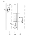
図7に示す先行車VL2は、自車両VL1前方の車幅範囲W1外にあるため、上述した条件1を満たしている。また、先行車VL2の対向車線に向かう進行方向D2と自車両VL1の進行方向D1とが交差してなす相対角度φは予め定められた閾値以上であり、上述した条件2および条件3を満たしている。従って、先行車VL2は、条件1~3を含むUターン条件を満たしている。先行車VL2がUターン条件を満たす場合の衝突推定領域R2は、Uターン条件を満たさない場合の衝突推定領域R1よりも拡張して設定される。このとき、衝突推定領域R2は、衝突推定領域R1よりも自車両VL1の進行方向D1と交差する方向にかつ、対向車線Ln3と反対側に拡張して設定されることが好ましい。本実施形態において、先行車VL2がUターン条件を満たす場合の衝突推定領域R2は、例えば、衝突推定領域幅RW2と衝突推定領域長RL2と推定領域角度θ1、θ2によって略六角形状に設定できる。より具体的には、衝突推定領域幅RW2と衝突推定領域長RL2とによって形成される略矩形状の4つのコーナー部のうち、先端側でかつ対向車線Ln3側のコーナー部において略三角形状の切欠部C1が削除されており、また、後端側でかつ対向車線Ln3と反対側のコーナー部において略三角形状の切欠部C2が削除されている。先端側に切欠部C1を設けることにより、先行車VL2がUターンにより対向車線Ln3の近くまで移動した場合には、先行車VL2と衝突する可能性が低いので、衝突する可能性があると推定しないことができる。また、後端側に切欠部C2を設けることにより、先行車VL2が自車両VL1と併走している場合には、先行車VL2と衝突する可能性が低いので、衝突する可能性があると推定しないことができる。ただし、衝突推定領域R2の形状は略六角形以外の形状(例えば略四角形)に設定してもよい。
Since the preceding vehicle VL2 shown in FIG. 7 is outside the vehicle width range W1 in front of the own vehicle VL1, the above-mentioned
衝突推定領域長RL2は、例えば、衝突推定領域長RL1と同様に、予め実験的に求めた自車両と他車両との相対速度と衝突推定領域長RL1との関係が定義されたマップや関数に基づき、算出できる。衝突推定領域幅RW2は、例えば、予め実験的に求めた先行車のヨー角速度と衝突推定領域幅RW2との関係が定義されたマップや関数に基づき、算出できる。推定領域角度θ1、θ2は、例えば、相対速度および先行車VL2の横速度と推定領域角度θ1、θ2との関係が定義されたマップや関数に基づき算出できる。本実施形態において「相対速度」とは自車両VL1の進行方向D1における自車両VL1と先行車VL2の速度差であり、「横速度」とは、自車両VL1の進行方向D1と垂直な方向における先行車VL2の速度である。推定領域角度θ1、θ2は、相対速度の増加および横速度の減少に伴い大きくなる。なお、推定領域角度θ1、θ2は0度以上90度以下であることが好ましい。また、推定領域角度θ1と推定領域角度θ2とは、同じ角度でもよい。 The collision estimation area length RL2 is, for example, a map or function in which the relationship between the relative speed between the own vehicle and another vehicle and the collision estimation area length RL1 obtained experimentally in advance is defined in the same manner as the collision estimation area length RL1. It can be calculated based on. The collision estimation area width RW2 can be calculated, for example, based on a map or a function in which the relationship between the yaw angular velocity of the preceding vehicle and the collision estimation area width RW2, which is experimentally obtained in advance, is defined. The estimated region angles θ1 and θ2 can be calculated based on, for example, a map or a function in which the relationship between the relative speed and the lateral speed of the preceding vehicle VL2 and the estimated region angles θ1 and θ2 is defined. In the present embodiment, the "relative speed" is the speed difference between the own vehicle VL1 and the preceding vehicle VL2 in the traveling direction D1 of the own vehicle VL1, and the "lateral speed" is the direction perpendicular to the traveling direction D1 of the own vehicle VL1. This is the speed of the preceding vehicle VL2. The estimated region angles θ1 and θ2 increase as the relative speed increases and the lateral speed decreases. The estimated region angles θ1 and θ2 are preferably 0 degrees or more and 90 degrees or less. Further, the estimated region angle θ1 and the estimated region angle θ2 may be the same angle.
図8は、縦軸は衝突推定領域幅RW2を示し、横軸は先行車VL2のヨー角速度を示す。図8に示すように、衝突推定領域幅RW2は、先行車VL2のヨー角速度の増加に伴い伸長する。 In FIG. 8, the vertical axis shows the collision estimation area width RW2, and the horizontal axis shows the yaw angular velocity of the preceding vehicle VL2. As shown in FIG. 8, the collision estimated region width RW2 extends as the yaw angular velocity of the preceding vehicle VL2 increases.
続いて、ステップS130(図2)において、衝突推定部114は、先行車と衝突する可能性があるか否か推定する。より具体的には、先行車の少なくとも一部がステップS120またはS125で設定した衝突推定領域内に存在するか否かを判定する。衝突する可能性がないと推定した場合、つまり、先行車が衝突推定領域に存在しない場合、ステップS100の処理に戻る。一方、衝突する可能性があると推定した場合、つまり、先行車が衝突推定領域に存在する場合、ステップS140に進み、衝突回避動作実行部116が予め定められた衝突回避動作を実行する。衝突回避動作は、プリクラッシュセーフティ(Pre Crash Safety(PCS(登録商標)))制御によって行われる動作であり、衝突を回避するための警告や自動ブレーキや、衝突による衝撃を緩和するための自動ブレーキやシートベルト自動巻き取りを含んでいる。ステップS140では、例えば、衝突回避動作実行部116が通知部140を制御して、車両の搭乗者に衝突の可能性があることを警告する。
Subsequently, in step S130 (FIG. 2), the
以上で説明した本実施形態の車両衝突推定装置110によれば、衝突推定領域設定部112は、先行車がUターン条件を満たす場合に、Uターン条件を満たさない場合よりも衝突推定領域を拡張するため、先行車のUターンを予測して衝突の可能性を推定できる。なお、本実施形態では、Uターンとして、図3に示すように、自車両VL1と同じ進行方向D1に走行する先行車VL2が、自車両VL1の走行する領域を横切って対向車線Ln3に進入する場合を想定して説明したが、これに限らず、例えば、対向車線Ln3を走行する他車両が、自車両VL1の走行する車線Ln2に進入するようなUターンにも適用してもよい。
According to the vehicle
B.その他の実施形態:
上述した実施形態において、衝突推定部114は、ステップS120において、先行車VL2のヨー角速度に応じて衝突推定領域幅RW2を設定している。この代わりに、先行車VL2の相対角度φや相対角度φの増加率、先行車VL2の横速度に応じて衝突推定領域幅RW2を設定してもよい。衝突推定領域幅RW2は、例えば、相対角度φが大きい場合に、相対角度φが小さい場合よりも大きく設定することができる。
B. Other embodiments:
In the above-described embodiment, the
本発明は、上述の実施形態に限られるものではなく、その趣旨を逸脱しない範囲において種々の構成で実現することができる。例えば発明の概要の欄に記載した各形態中の技術的特徴に対応する実施形態中の技術的特徴は、上述した課題を解決するために、あるいは上述の効果の一部又は全部を達成するために、適宜、差し替えや組み合わせを行うことが可能である。また、その技術的特徴が本明細書中に必須なものとして説明されていなければ、適宜削除することが可能である。 The present invention is not limited to the above-described embodiment, and can be realized with various configurations within a range not deviating from the gist thereof. For example, the technical features in the embodiments corresponding to the technical features in each embodiment described in the column of the outline of the invention are for solving the above-mentioned problems or for achieving a part or all of the above-mentioned effects. In addition, it is possible to replace or combine them as appropriate. Further, if the technical feature is not described as essential in the present specification, it can be appropriately deleted.
100 車両、110 車両衝突推定装置、112 衝突推定領域設定部、114 衝突推定部、116 衝突回避動作実行部、120 周辺センサ、122 周辺認識カメラ、124 周辺物体センサ、126 自車位置センサ、130 道路情報記憶部、140 通知部、210 運転制御ECU、220 駆動力制御ECU、230 制動力制御ECU、240 操舵制御ECU、250 車載ネットワーク 100 vehicle, 110 vehicle collision estimation device, 112 collision estimation area setting unit, 114 collision estimation unit, 116 collision avoidance operation execution unit, 120 peripheral sensor, 122 peripheral recognition camera, 124 peripheral object sensor, 126 own vehicle position sensor, 130 road Information storage unit, 140 notification unit, 210 operation control ECU, 220 driving force control ECU, 230 braking force control ECU, 240 steering control ECU, 250 in-vehicle network
Claims (4)
前記車両の前方に衝突推定領域を設定する衝突推定領域設定部(112)と、
前記先行車が前記衝突推定領域内に存在する場合に、前記車両と前記先行車とが衝突する可能性があると推定する衝突推定部(114)と、
前記衝突推定部によって前記車両と前記先行車とが衝突する可能性があると推定された場合に、予め定められた衝突回避動作を実行する衝突回避動作実行部(116)と、を備え、
前記衝突推定領域設定部は、前記先行車が前記車両の前方を横切ってUターンする可能性が高いことを示す予め定めたUターン条件を満たす場合に、前記先行車が前記Uターン条件を満たさない場合よりも前記車両の進行方向と交差する方向における前記衝突推定領域の幅を、前記車両の対向車線と反対側に向けて拡張し、かつ、前記先行車のヨー角度速度が大きい場合に前記ヨー角度速度が小さい場合よりも拡張し、
前記Uターン条件は、前記先行車が前記車両の車幅範囲よりも前記車両の対向車線と反対側の範囲にあるという第1条件を含む、車両衝突推定装置。 A vehicle collision estimation device (110) mounted on a vehicle (100) provided with a peripheral sensor (120) for detecting a preceding vehicle.
A collision estimation area setting unit (112) that sets a collision estimation area in front of the vehicle, and a collision estimation area setting unit (112).
A collision estimation unit (114) that estimates that the vehicle and the preceding vehicle may collide when the preceding vehicle is in the collision estimation region.
A collision avoidance operation execution unit (116) that executes a predetermined collision avoidance operation when it is estimated by the collision estimation unit that the vehicle and the preceding vehicle may collide with each other is provided.
The collision estimation area setting unit satisfies the U-turn condition when the predetermined U-turn condition indicating that the preceding vehicle is likely to make a U-turn across the front of the vehicle is satisfied. The width of the collision estimation region in the direction intersecting the traveling direction of the vehicle is expanded toward the opposite side of the oncoming lane of the vehicle , and the yaw angle speed of the preceding vehicle is larger than in the case of no vehicle. Expanded than when the yaw angle velocity is small,
The U-turn condition is a vehicle collision estimation device including a first condition that the preceding vehicle is in a range opposite to the oncoming lane of the vehicle from the vehicle width range of the vehicle.
前記Uターン条件は、
前記先行車の進行方向が前記対向車線に向かうように前記車両の進行方向と交差しているという第2条件と、
前記車両の進行方向を基準とした前記先行車の進行方向のなす相対角度と前記相対角度の増加率とのうち少なくとも一方が予め定められた閾値以上であるという第3条件と、のうちの少なくとも1つを含む、車両衝突推定装置。 The vehicle collision estimation device according to claim 1.
The U-turn condition is
The second condition that the traveling direction of the preceding vehicle intersects with the traveling direction of the vehicle so as to face the oncoming lane, and
At least one of the third condition that at least one of the relative angle formed by the traveling direction of the preceding vehicle and the rate of increase of the relative angle with respect to the traveling direction of the vehicle is equal to or higher than a predetermined threshold value. Vehicle collision estimation device including one.
前記Uターン条件は、更に、
前記先行車の前記車両側のウィンカーが点灯しているという第4条件と、
前記先行車の速度が予め定められた閾値以下であるという第5条件と、のうちの少なくとも1つを含む車両衝突推定装置。 The vehicle collision estimation device according to claim 2.
The U-turn condition further
The fourth condition that the turn signal on the vehicle side of the preceding vehicle is lit, and
A vehicle collision estimation device including at least one of a fifth condition that the speed of the preceding vehicle is equal to or less than a predetermined threshold value.
前記車両の前方に衝突推定領域を設定する衝突推定領域設定部と、
前記先行車が前記衝突推定領域内に存在する場合に、前記車両と前記先行車とが衝突する可能性があると推定する衝突推定部と、
前記衝突推定部によって前記車両と前記先行車とが衝突する可能性があると推定された
場合に、予め定められた衝突回避動作を実行する衝突回避動作実行部と、を備え、
前記衝突推定領域設定部は、前記先行車が前記車両の前方を横切ってUターンする可能性が高いことを示すことを推定させる予め定めたUターン条件を満たす場合に、前記先行車が前記Uターン条件を満たさない場合よりも前記衝突推定領域を拡張し、かつ、前記先行車のヨー角度速度が大きい場合に前記ヨー角度速度が小さい場合よりも拡張し、
前記Uターン条件は、前記先行車が前記車両の車幅範囲よりも前記車両の対向車線と反対側の範囲にあるという条件と、前記先行車の前記車両側のウィンカーが点灯しているという条件を含む、車両衝突推定装置。 A vehicle collision estimation device mounted on a vehicle equipped with a peripheral sensor that detects a preceding vehicle.
A collision estimation area setting unit that sets a collision estimation area in front of the vehicle, and a collision estimation area setting unit.
A collision estimation unit that estimates that the vehicle and the preceding vehicle may collide when the preceding vehicle is within the collision estimation region.
It was estimated by the collision estimation unit that the vehicle and the preceding vehicle may collide with each other.
In some cases, it is equipped with a collision avoidance operation execution unit that executes a predetermined collision avoidance operation .
When the collision estimation area setting unit satisfies a predetermined U-turn condition for presuming that the preceding vehicle is likely to make a U-turn across the front of the vehicle, the preceding vehicle makes the U-turn. The collision estimation area is expanded more than when the turn condition is not satisfied, and when the yaw angle speed of the preceding vehicle is large, it is expanded more than when the yaw angle speed is small.
The U-turn condition is a condition that the preceding vehicle is in a range opposite to the oncoming lane of the vehicle from the vehicle width range of the vehicle, and a condition that the winker on the vehicle side of the preceding vehicle is lit. Including vehicle collision estimation device.
Priority Applications (3)
| Application Number | Priority Date | Filing Date | Title |
|---|---|---|---|
| JP2018082089A JP7014032B2 (en) | 2018-04-23 | 2018-04-23 | Vehicle collision estimation device |
| PCT/JP2019/016263 WO2019208320A1 (en) | 2018-04-23 | 2019-04-16 | Vehicle collision estimating device |
| US17/075,977 US11872983B2 (en) | 2018-04-23 | 2020-10-21 | Vehicle collision prediction apparatus |
Applications Claiming Priority (1)
| Application Number | Priority Date | Filing Date | Title |
|---|---|---|---|
| JP2018082089A JP7014032B2 (en) | 2018-04-23 | 2018-04-23 | Vehicle collision estimation device |
Publications (3)
| Publication Number | Publication Date |
|---|---|
| JP2019188936A JP2019188936A (en) | 2019-10-31 |
| JP2019188936A5 JP2019188936A5 (en) | 2020-05-14 |
| JP7014032B2 true JP7014032B2 (en) | 2022-02-01 |
Family
ID=68294936
Family Applications (1)
| Application Number | Title | Priority Date | Filing Date |
|---|---|---|---|
| JP2018082089A Active JP7014032B2 (en) | 2018-04-23 | 2018-04-23 | Vehicle collision estimation device |
Country Status (3)
| Country | Link |
|---|---|
| US (1) | US11872983B2 (en) |
| JP (1) | JP7014032B2 (en) |
| WO (1) | WO2019208320A1 (en) |
Families Citing this family (6)
| Publication number | Priority date | Publication date | Assignee | Title |
|---|---|---|---|---|
| DE102017202415A1 (en) * | 2017-02-15 | 2018-08-16 | Bayerische Motoren Werke Aktiengesellschaft | Collision avoidance with cross traffic |
| DE102017223486A1 (en) * | 2017-12-21 | 2019-06-27 | Continental Teves Ag & Co. Ohg | Method and system for avoiding lateral collisions |
| JP7014032B2 (en) * | 2018-04-23 | 2022-02-01 | 株式会社デンソー | Vehicle collision estimation device |
| JP2020175803A (en) * | 2019-04-19 | 2020-10-29 | マツダ株式会社 | Vehicle control device |
| KR20220092303A (en) * | 2020-12-24 | 2022-07-01 | 현대자동차주식회사 | Vehicle and control method thereof |
| KR102473714B1 (en) * | 2021-05-07 | 2022-12-06 | 현대모비스 주식회사 | Vehicle control system for detecting object and method thereof |
Citations (1)
| Publication number | Priority date | Publication date | Assignee | Title |
|---|---|---|---|---|
| JP2017076235A (en) | 2015-10-14 | 2017-04-20 | 株式会社デンソー | Vehicle control device and vehicle control method |
Family Cites Families (14)
| Publication number | Priority date | Publication date | Assignee | Title |
|---|---|---|---|---|
| JP2007099237A (en) * | 2005-10-07 | 2007-04-19 | Fuji Heavy Ind Ltd | Vehicle drive support device |
| US7881868B2 (en) * | 2007-06-12 | 2011-02-01 | Palo Alto Research Center Incorporated | Dual assessment for early collision warning |
| JP5015849B2 (en) | 2008-04-11 | 2012-08-29 | トヨタ自動車株式会社 | Reverse running warning device, reverse running warning method |
| JP5407952B2 (en) | 2009-06-18 | 2014-02-05 | 日産自動車株式会社 | Vehicle driving support device and vehicle driving support method |
| JP2016015043A (en) | 2014-07-02 | 2016-01-28 | トヨタ自動車株式会社 | Object recognition device |
| US9248834B1 (en) * | 2014-10-02 | 2016-02-02 | Google Inc. | Predicting trajectories of objects based on contextual information |
| WO2017056401A1 (en) * | 2015-09-30 | 2017-04-06 | ソニー株式会社 | Control device, control method, and program |
| JP6504042B2 (en) | 2015-12-17 | 2019-04-24 | 株式会社デンソー | Control device, control method |
| JP6569523B2 (en) | 2015-12-25 | 2019-09-04 | 株式会社デンソー | Driving support device |
| JP6229003B2 (en) * | 2016-04-04 | 2017-11-08 | 株式会社小松製作所 | Transport vehicle |
| JP6775881B2 (en) * | 2016-09-29 | 2020-10-28 | ダイハツ工業株式会社 | Vehicle control device |
| WO2018220853A1 (en) * | 2017-06-02 | 2018-12-06 | 本田技研工業株式会社 | Vehicle control device and method for controlling autonomous driving vehicle |
| US20190101924A1 (en) * | 2017-10-03 | 2019-04-04 | Uber Technologies, Inc. | Anomaly Detection Systems and Methods for Autonomous Vehicles |
| JP7014032B2 (en) * | 2018-04-23 | 2022-02-01 | 株式会社デンソー | Vehicle collision estimation device |
-
2018
- 2018-04-23 JP JP2018082089A patent/JP7014032B2/en active Active
-
2019
- 2019-04-16 WO PCT/JP2019/016263 patent/WO2019208320A1/en active Application Filing
-
2020
- 2020-10-21 US US17/075,977 patent/US11872983B2/en active Active
Patent Citations (1)
| Publication number | Priority date | Publication date | Assignee | Title |
|---|---|---|---|---|
| JP2017076235A (en) | 2015-10-14 | 2017-04-20 | 株式会社デンソー | Vehicle control device and vehicle control method |
Also Published As
| Publication number | Publication date |
|---|---|
| US11872983B2 (en) | 2024-01-16 |
| WO2019208320A1 (en) | 2019-10-31 |
| JP2019188936A (en) | 2019-10-31 |
| US20210031762A1 (en) | 2021-02-04 |
Similar Documents
| Publication | Publication Date | Title |
|---|---|---|
| JP7014032B2 (en) | Vehicle collision estimation device | |
| US11803026B2 (en) | Camera system for intelligent driver assistance system, and driver assistance system and method | |
| US9669760B2 (en) | Warning device | |
| JP5919150B2 (en) | Driving assistance device | |
| JP5626475B2 (en) | Driving assistance device | |
| CN111942352B (en) | Adaptive AEB system considering steering path and control method thereof | |
| US10919449B2 (en) | Driving support device and storage medium | |
| US20120065841A1 (en) | Vehicle surrounding monitor device and method for monitoring surroundings used for vehicle | |
| WO2018074287A1 (en) | Vehicle control device | |
| JP6740969B2 (en) | Braking assistance device and braking assistance control method in vehicle | |
| JP2006338200A (en) | Vehicle deviation preventive control device | |
| JP6384534B2 (en) | Vehicle target detection system | |
| KR20200094378A (en) | Driver assistance system and controlling method thereof | |
| JP6828429B2 (en) | Vehicle collision avoidance support device and vehicle collision avoidance support method | |
| JP5796519B2 (en) | Driving assistance device | |
| US20200216074A1 (en) | Control system of vehicle, control method of the same, and non-transitory computer-readable storage medium | |
| JP5452004B2 (en) | Vehicle driving support device | |
| JP7044000B2 (en) | Vehicle control device and vehicle control method | |
| US20210162992A1 (en) | Driver assistance device | |
| US20220227359A1 (en) | Vehicle control apparatus | |
| JP4294450B2 (en) | Vehicle driving support device | |
| WO2019202859A1 (en) | Travel control device | |
| JP5267444B2 (en) | Driving assistance device | |
| US20240109522A1 (en) | Driving support apparatus, driving support method, and non-transitory computer-readable storage medium | |
| US20220242485A1 (en) | Driver assistance system and control method for the same |
Legal Events
| Date | Code | Title | Description |
|---|---|---|---|
| A521 | Request for written amendment filed |
Free format text: JAPANESE INTERMEDIATE CODE: A523 Effective date: 20200402 |
|
| A621 | Written request for application examination |
Free format text: JAPANESE INTERMEDIATE CODE: A621 Effective date: 20201001 |
|
| A131 | Notification of reasons for refusal |
Free format text: JAPANESE INTERMEDIATE CODE: A131 Effective date: 20210706 |
|
| A521 | Request for written amendment filed |
Free format text: JAPANESE INTERMEDIATE CODE: A523 Effective date: 20210810 |
|
| TRDD | Decision of grant or rejection written | ||
| A01 | Written decision to grant a patent or to grant a registration (utility model) |
Free format text: JAPANESE INTERMEDIATE CODE: A01 Effective date: 20211221 |
|
| A61 | First payment of annual fees (during grant procedure) |
Free format text: JAPANESE INTERMEDIATE CODE: A61 Effective date: 20220103 |