JP6535194B2 - Vehicle control device and vehicle control method - Google Patents
Vehicle control device and vehicle control method Download PDFInfo
- Publication number
- JP6535194B2 JP6535194B2 JP2015072923A JP2015072923A JP6535194B2 JP 6535194 B2 JP6535194 B2 JP 6535194B2 JP 2015072923 A JP2015072923 A JP 2015072923A JP 2015072923 A JP2015072923 A JP 2015072923A JP 6535194 B2 JP6535194 B2 JP 6535194B2
- Authority
- JP
- Japan
- Prior art keywords
- condition
- vehicle
- correction
- target
- safety device
- Prior art date
- Legal status (The legal status is an assumption and is not a legal conclusion. Google has not performed a legal analysis and makes no representation as to the accuracy of the status listed.)
- Active
Links
- 238000000034 method Methods 0.000 title claims description 25
- 238000012937 correction Methods 0.000 claims description 127
- 230000008569 process Effects 0.000 description 17
- 230000033228 biological regulation Effects 0.000 description 16
- 238000012545 processing Methods 0.000 description 10
- 238000001514 detection method Methods 0.000 description 9
- 238000003384 imaging method Methods 0.000 description 9
- 230000000694 effects Effects 0.000 description 7
- 230000001133 acceleration Effects 0.000 description 2
- 230000005540 biological transmission Effects 0.000 description 2
- 230000007423 decrease Effects 0.000 description 2
- 238000000605 extraction Methods 0.000 description 2
- 230000004927 fusion Effects 0.000 description 2
- 241000287107 Passer Species 0.000 description 1
- 240000004050 Pentaglottis sempervirens Species 0.000 description 1
- 235000004522 Pentaglottis sempervirens Nutrition 0.000 description 1
- 230000009471 action Effects 0.000 description 1
- 238000013459 approach Methods 0.000 description 1
- 230000008859 change Effects 0.000 description 1
- 238000010586 diagram Methods 0.000 description 1
- 239000000284 extract Substances 0.000 description 1
- 230000005484 gravity Effects 0.000 description 1
- 230000004048 modification Effects 0.000 description 1
- 238000012986 modification Methods 0.000 description 1
Images


Classifications
-
- G—PHYSICS
- G08—SIGNALLING
- G08G—TRAFFIC CONTROL SYSTEMS
- G08G1/00—Traffic control systems for road vehicles
- G08G1/16—Anti-collision systems
- G08G1/166—Anti-collision systems for active traffic, e.g. moving vehicles, pedestrians, bikes
-
- B—PERFORMING OPERATIONS; TRANSPORTING
- B60—VEHICLES IN GENERAL
- B60Q—ARRANGEMENT OF SIGNALLING OR LIGHTING DEVICES, THE MOUNTING OR SUPPORTING THEREOF OR CIRCUITS THEREFOR, FOR VEHICLES IN GENERAL
- B60Q9/00—Arrangement or adaptation of signal devices not provided for in one of main groups B60Q1/00 - B60Q7/00, e.g. haptic signalling
- B60Q9/008—Arrangement or adaptation of signal devices not provided for in one of main groups B60Q1/00 - B60Q7/00, e.g. haptic signalling for anti-collision purposes
-
- B—PERFORMING OPERATIONS; TRANSPORTING
- B60—VEHICLES IN GENERAL
- B60T—VEHICLE BRAKE CONTROL SYSTEMS OR PARTS THEREOF; BRAKE CONTROL SYSTEMS OR PARTS THEREOF, IN GENERAL; ARRANGEMENT OF BRAKING ELEMENTS ON VEHICLES IN GENERAL; PORTABLE DEVICES FOR PREVENTING UNWANTED MOVEMENT OF VEHICLES; VEHICLE MODIFICATIONS TO FACILITATE COOLING OF BRAKES
- B60T7/00—Brake-action initiating means
- B60T7/12—Brake-action initiating means for automatic initiation; for initiation not subject to will of driver or passenger
- B60T7/22—Brake-action initiating means for automatic initiation; for initiation not subject to will of driver or passenger initiated by contact of vehicle, e.g. bumper, with an external object, e.g. another vehicle, or by means of contactless obstacle detectors mounted on the vehicle
-
- B—PERFORMING OPERATIONS; TRANSPORTING
- B60—VEHICLES IN GENERAL
- B60W—CONJOINT CONTROL OF VEHICLE SUB-UNITS OF DIFFERENT TYPE OR DIFFERENT FUNCTION; CONTROL SYSTEMS SPECIALLY ADAPTED FOR HYBRID VEHICLES; ROAD VEHICLE DRIVE CONTROL SYSTEMS FOR PURPOSES NOT RELATED TO THE CONTROL OF A PARTICULAR SUB-UNIT
- B60W30/00—Purposes of road vehicle drive control systems not related to the control of a particular sub-unit, e.g. of systems using conjoint control of vehicle sub-units
- B60W30/08—Active safety systems predicting or avoiding probable or impending collision or attempting to minimise its consequences
- B60W30/09—Taking automatic action to avoid collision, e.g. braking and steering
-
- G—PHYSICS
- G01—MEASURING; TESTING
- G01S—RADIO DIRECTION-FINDING; RADIO NAVIGATION; DETERMINING DISTANCE OR VELOCITY BY USE OF RADIO WAVES; LOCATING OR PRESENCE-DETECTING BY USE OF THE REFLECTION OR RERADIATION OF RADIO WAVES; ANALOGOUS ARRANGEMENTS USING OTHER WAVES
- G01S13/00—Systems using the reflection or reradiation of radio waves, e.g. radar systems; Analogous systems using reflection or reradiation of waves whose nature or wavelength is irrelevant or unspecified
- G01S13/86—Combinations of radar systems with non-radar systems, e.g. sonar, direction finder
- G01S13/867—Combination of radar systems with cameras
-
- G—PHYSICS
- G01—MEASURING; TESTING
- G01S—RADIO DIRECTION-FINDING; RADIO NAVIGATION; DETERMINING DISTANCE OR VELOCITY BY USE OF RADIO WAVES; LOCATING OR PRESENCE-DETECTING BY USE OF THE REFLECTION OR RERADIATION OF RADIO WAVES; ANALOGOUS ARRANGEMENTS USING OTHER WAVES
- G01S13/00—Systems using the reflection or reradiation of radio waves, e.g. radar systems; Analogous systems using reflection or reradiation of waves whose nature or wavelength is irrelevant or unspecified
- G01S13/88—Radar or analogous systems specially adapted for specific applications
- G01S13/93—Radar or analogous systems specially adapted for specific applications for anti-collision purposes
- G01S13/931—Radar or analogous systems specially adapted for specific applications for anti-collision purposes of land vehicles
-
- G—PHYSICS
- G08—SIGNALLING
- G08G—TRAFFIC CONTROL SYSTEMS
- G08G1/00—Traffic control systems for road vehicles
- G08G1/16—Anti-collision systems
- G08G1/165—Anti-collision systems for passive traffic, e.g. including static obstacles, trees
-
- B—PERFORMING OPERATIONS; TRANSPORTING
- B60—VEHICLES IN GENERAL
- B60T—VEHICLE BRAKE CONTROL SYSTEMS OR PARTS THEREOF; BRAKE CONTROL SYSTEMS OR PARTS THEREOF, IN GENERAL; ARRANGEMENT OF BRAKING ELEMENTS ON VEHICLES IN GENERAL; PORTABLE DEVICES FOR PREVENTING UNWANTED MOVEMENT OF VEHICLES; VEHICLE MODIFICATIONS TO FACILITATE COOLING OF BRAKES
- B60T2201/00—Particular use of vehicle brake systems; Special systems using also the brakes; Special software modules within the brake system controller
- B60T2201/02—Active or adaptive cruise control system; Distance control
- B60T2201/022—Collision avoidance systems
-
- B—PERFORMING OPERATIONS; TRANSPORTING
- B60—VEHICLES IN GENERAL
- B60W—CONJOINT CONTROL OF VEHICLE SUB-UNITS OF DIFFERENT TYPE OR DIFFERENT FUNCTION; CONTROL SYSTEMS SPECIALLY ADAPTED FOR HYBRID VEHICLES; ROAD VEHICLE DRIVE CONTROL SYSTEMS FOR PURPOSES NOT RELATED TO THE CONTROL OF A PARTICULAR SUB-UNIT
- B60W2554/00—Input parameters relating to objects
-
- B—PERFORMING OPERATIONS; TRANSPORTING
- B60—VEHICLES IN GENERAL
- B60W—CONJOINT CONTROL OF VEHICLE SUB-UNITS OF DIFFERENT TYPE OR DIFFERENT FUNCTION; CONTROL SYSTEMS SPECIALLY ADAPTED FOR HYBRID VEHICLES; ROAD VEHICLE DRIVE CONTROL SYSTEMS FOR PURPOSES NOT RELATED TO THE CONTROL OF A PARTICULAR SUB-UNIT
- B60W2555/00—Input parameters relating to exterior conditions, not covered by groups B60W2552/00, B60W2554/00
- B60W2555/60—Traffic rules, e.g. speed limits or right of way
- B60W2555/80—Country specific, e.g. driver age limits or right hand drive
-
- B—PERFORMING OPERATIONS; TRANSPORTING
- B62—LAND VEHICLES FOR TRAVELLING OTHERWISE THAN ON RAILS
- B62D—MOTOR VEHICLES; TRAILERS
- B62D15/00—Steering not otherwise provided for
- B62D15/02—Steering position indicators ; Steering position determination; Steering aids
- B62D15/025—Active steering aids, e.g. helping the driver by actively influencing the steering system after environment evaluation
- B62D15/0265—Automatic obstacle avoidance by steering
-
- G—PHYSICS
- G01—MEASURING; TESTING
- G01S—RADIO DIRECTION-FINDING; RADIO NAVIGATION; DETERMINING DISTANCE OR VELOCITY BY USE OF RADIO WAVES; LOCATING OR PRESENCE-DETECTING BY USE OF THE REFLECTION OR RERADIATION OF RADIO WAVES; ANALOGOUS ARRANGEMENTS USING OTHER WAVES
- G01S13/00—Systems using the reflection or reradiation of radio waves, e.g. radar systems; Analogous systems using reflection or reradiation of waves whose nature or wavelength is irrelevant or unspecified
- G01S13/88—Radar or analogous systems specially adapted for specific applications
- G01S13/93—Radar or analogous systems specially adapted for specific applications for anti-collision purposes
- G01S13/931—Radar or analogous systems specially adapted for specific applications for anti-collision purposes of land vehicles
- G01S2013/9318—Controlling the steering
-
- G—PHYSICS
- G01—MEASURING; TESTING
- G01S—RADIO DIRECTION-FINDING; RADIO NAVIGATION; DETERMINING DISTANCE OR VELOCITY BY USE OF RADIO WAVES; LOCATING OR PRESENCE-DETECTING BY USE OF THE REFLECTION OR RERADIATION OF RADIO WAVES; ANALOGOUS ARRANGEMENTS USING OTHER WAVES
- G01S13/00—Systems using the reflection or reradiation of radio waves, e.g. radar systems; Analogous systems using reflection or reradiation of waves whose nature or wavelength is irrelevant or unspecified
- G01S13/88—Radar or analogous systems specially adapted for specific applications
- G01S13/93—Radar or analogous systems specially adapted for specific applications for anti-collision purposes
- G01S13/931—Radar or analogous systems specially adapted for specific applications for anti-collision purposes of land vehicles
- G01S2013/93185—Controlling the brakes
-
- G—PHYSICS
- G01—MEASURING; TESTING
- G01S—RADIO DIRECTION-FINDING; RADIO NAVIGATION; DETERMINING DISTANCE OR VELOCITY BY USE OF RADIO WAVES; LOCATING OR PRESENCE-DETECTING BY USE OF THE REFLECTION OR RERADIATION OF RADIO WAVES; ANALOGOUS ARRANGEMENTS USING OTHER WAVES
- G01S13/00—Systems using the reflection or reradiation of radio waves, e.g. radar systems; Analogous systems using reflection or reradiation of waves whose nature or wavelength is irrelevant or unspecified
- G01S13/88—Radar or analogous systems specially adapted for specific applications
- G01S13/93—Radar or analogous systems specially adapted for specific applications for anti-collision purposes
- G01S13/931—Radar or analogous systems specially adapted for specific applications for anti-collision purposes of land vehicles
- G01S2013/932—Radar or analogous systems specially adapted for specific applications for anti-collision purposes of land vehicles using own vehicle data, e.g. ground speed, steering wheel direction
Landscapes
- Engineering & Computer Science (AREA)
- Radar, Positioning & Navigation (AREA)
- Remote Sensing (AREA)
- Physics & Mathematics (AREA)
- General Physics & Mathematics (AREA)
- Mechanical Engineering (AREA)
- Transportation (AREA)
- Computer Networks & Wireless Communication (AREA)
- Automation & Control Theory (AREA)
- Electromagnetism (AREA)
- Human Computer Interaction (AREA)
- Traffic Control Systems (AREA)
Description
本発明は、自車両と、自車両の進行方向前方等の周囲に位置する物標との衝突の危険性が増加した場合に、自車両に備えられた安全装置を作動させる車両制御装置、及びその車両制御装置が実行する車両制御方法に関する。 The present invention relates to a vehicle control device that operates a safety device provided in the host vehicle when the risk of a collision between the host vehicle and a target located around the host vehicle such as in the forward direction of the host vehicle increases. The present invention relates to a vehicle control method executed by the vehicle control device.
従来、自車両と、自車両の進行方向前方に位置する他車両、歩行者、又は道路構造物等の物標との衝突被害を軽減または防止する、プリクラッシュセーフティ(PCS)が実現されている。PCSでは、自車両と物標との相対距離と、相対速度又は相対加速度とに基づいて、自車両と物標との衝突までの時間である衝突予測時間(TTC:Time to Collision)を求め、衝突予測時間に基づいて、自車両の運転者に対して警報装置により接近を報知したり、自車両の制動装置を作動させたりしている。 Conventionally, a pre-crash safety (PCS) has been realized that reduces or prevents collision damage between the vehicle and a target such as another vehicle, a pedestrian, or a road structure located in front of the vehicle in the traveling direction. . In PCS, based on the relative distance between the host vehicle and the target and the relative velocity or relative acceleration, a collision prediction time (TTC: Time to Collision) which is the time until the collision between the host vehicle and the target is determined. Based on the predicted collision time, the driver of the host vehicle is notified of the approach by the alarm device, or the braking device of the host vehicle is operated.
このような車両制御装置は、一般的に、その車両を使用する国や地域等に応じて設定を変更する必要がある。例えば、国や地域等ごとに適合させることができる装置として、特許文献1に記載の車両用表示装置がある。特許文献1の車両用表示装置では、各国の法規等に基づいて、異なる表示項目を選択して表示パネルに表示している。
Such a vehicle control device generally needs to be changed in setting according to the country, region, etc. in which the vehicle is used. For example, as a device that can be adapted to each country, region, etc., there is a display device for vehicle described in
PCSでは、安全装置を作動させるうえで、自車両の走行状態や、自車両と物標との位置関係等の様々な条件を考慮する必要がある。このような様々な条件を、国や地域等ごとに設定すれば、データ量が増大する問題が生ずる。 In PCS, when operating the safety device, it is necessary to consider various conditions such as the traveling state of the vehicle and the positional relationship between the vehicle and the target. If such various conditions are set for each country, area, etc., there arises a problem that the amount of data increases.
本発明は、上記課題を解決するためになされたものであり、その主たる目的は、安全装置を国や地域等に合わせて作動させるうえで、その安全装置の作動に関するデータ量を低減することができる車両制御装置を提供することにある。 The present invention has been made to solve the above-mentioned problems, and its main object is to reduce the amount of data related to the operation of the safety device when the safety device is operated according to the country, region, etc. And providing a vehicle control device that can
第1の発明は、自車両と、自車両の周囲に存在する物標とが衝突する危険性が高まったとき、自車両と物標との衝突の回避又は衝突被害を軽減する装置を安全装置として作動させる車両制御装置であって、前記安全装置を作動させる条件である作動条件を設定する条件設定手段と、前記作動条件に対する複数の補正条件について、それぞれを満たすか否かを判定する補正判定手段と、前記作動条件に基づいて、前記安全装置を作動させるか否かを判定する作動判定手段と、を備え、前記条件設定手段は、予め定められた基準条件を、前記補正判定手段が満たしたと判定した補正条件に基づいて補正したうえで、自車両が使用される国や地域等である仕向地ごとに定められた補正値である仕向補正値により補正することにより、前記作動条件を設定することを特徴とする。 The first invention relates to a device for preventing or reducing a collision between a host vehicle and a target or reducing a collision damage when the risk of the host vehicle colliding with the target existing around the host vehicle is increased. A vehicle control device operated as the condition setting means for setting an operation condition which is a condition for operating the safety device, and a correction determination determining whether or not each of a plurality of correction conditions for the operation condition is satisfied Means, and operation determination means for determining whether or not to operate the safety device based on the operation condition, the condition setting means satisfying the reference conditions set in advance, the correction determination means satisfying The operating condition is corrected by correcting with the destination correction value which is a correction value determined for each destination, which is a country or region where the vehicle is used, after correcting based on the correction condition determined to be Characterized in that it constant.
上記構成では、複数の補正条件に対して補正値を設定しているため、作動条件の細かな設定が可能であり、安全装置を精度良く作動させることができる。一方、複数の補正条件についての補正値を仕向地ごとに設けるものとすれば、データ量が増大する。この点、作動条件を求めるうえで、各補正条件に基づいて補正したうえで、仕向地ごとに設定される仕向補正値により補正している。これにより、安全装置の作動条件の細かな設定を可能としつつ、データ量の増大を抑制することができる。 In the above configuration, since the correction values are set for a plurality of correction conditions, the operating conditions can be set finely, and the safety device can be operated with high accuracy. On the other hand, if correction values for a plurality of correction conditions are provided for each destination, the amount of data increases. In this regard, in order to obtain the operating conditions, after correcting based on each correction condition, the correction is made using the destination correction value set for each destination. This makes it possible to suppress an increase in the amount of data while enabling the detailed setting of the operating conditions of the safety device.
また、第2の発明は、自車両と、自車両の周囲に存在する物標とが衝突する危険性が高まったとき、自車両と物標との衝突の回避又は衝突被害を軽減する装置を安全装置として作動させる車両制御装置であって、自車両と、自車両の周囲に存在する物標とが衝突する危険性が高まったとき、自車両と物標との衝突の回避又は衝突被害を軽減する装置を安全装置として作動させる車両制御装置(10)であって、前記安全装置を作動させる条件である作動条件を設定する条件設定手段と、前記作動条件に対する複数の補正条件について、それぞれを満たすか否かを判定する補正判定手段と、前記作動条件と基づいて、前記安全装置を作動させるか否かを判定する作動判定手段と、を備え、前記条件設定手段は、自車両が使用される国や地域等である仕向地ごとに定められた基準条件を、前記補正判定手段が満たしたと判定した補正条件に基づいて補正することにより、前記作動条件を設定することを特徴とする。 The second invention is an apparatus for avoiding or reducing the collision damage between the host vehicle and the target when the risk of the host vehicle colliding with the target existing around the host vehicle increases. A vehicle control device operated as a safety device, which avoids collision or collision damage between the subject vehicle and the target when the risk of the subject vehicle colliding with the target existing around the subject vehicle increases. A vehicle control device (10) for operating the device to be mitigated as a safety device, wherein condition setting means for setting an operation condition which is a condition for operating the safety device, and a plurality of correction conditions for the operation condition And the operation determination means for determining whether or not to operate the safety device based on the operation condition, and the condition setting means uses the vehicle. Country or region That the reference conditions specified for each destination, by correcting on the basis of a correction condition it is determined that the correction determination means satisfies, and sets the operating conditions.
上記構成では、作動条件を求めるうえで、仕向地ごとに設定した基準条件に対して、補正条件に基づいて補正しているため、安全装置の作動条件の細かな設定を可能としつつ、データ量の増大を抑制することができる。 In the above configuration, since the reference condition set for each destination is corrected based on the correction condition in order to obtain the operating condition, the data amount can be made while enabling the detailed setting of the operating condition of the safety device. Can be suppressed.
<第1実施形態>
本実施形態に係る車両制御装置は、車両(自車両)に搭載され、自車両の進行方向前方等の周囲に存在する物標を検知し、車両制御方法を実行することで、その物標との衝突を回避すべく、若しくは衝突被害を軽減すべく制御を行うPCSシステムとして機能する。
First Embodiment
The vehicle control device according to the present embodiment is mounted on a vehicle (self-vehicle), detects a target existing around the forward direction of the self-vehicle, etc., and executes the vehicle control method. Function as a PCS system that performs control to avoid or reduce collision damage.
図1において、車両制御装置である車両制御ECU10は、CPU、ROM、RAM、I/O等を備えたコンピュータである。この車両制御ECU10は、CPUが、ROMにインストールされているプログラムを実行することでこれら各機能を実現する。
In FIG. 1, a
車両制御ECU10には、各種の検知情報を入力するセンサ装置として、レーダ装置21、撮像装置22、車速センサ23及びヨーレートセンサ24が接続されている。
A
レーダ装置21は、例えば、ミリ波帯の高周波信号を送信波とする公知のミリ波レーダであり、自車両の前端部に設けられ、所定の検知角に入る領域を物標を検知可能な検知範囲とし、検知範囲内の物標の位置を検出する。具体的には、所定周期で探査波を送信し、複数のアンテナにより反射波を受信する。この探査波の送信時刻と反射波の受信時刻とにより、物標との距離を算出する。また、物標に反射された反射波の、ドップラー効果により変化した周波数により、相対速度を算出する。加えて、複数のアンテナが受信した反射波の位相差により、物標の方位を算出する。なお、物標の位置及び方位が算出できれば、その物標の、自車両に対する相対位置を特定することができる。なお、レーダ装置21は、所定周期毎に、探査波の送信、反射波の受信、反射位置及び相対速度の算出を行い、算出した反射位置と相対速度とを車両制御ECU10に送信する。
The
撮像装置22は、例えばCCDカメラ、CMOSイメージセンサ、近赤外線カメラ等の単眼撮像装置である。撮像装置22は、車両の車幅方向中央の所定高さに取り付けられており、車両前方へ向けて所定角度範囲で広がる領域を俯瞰視点から撮像する。撮像装置22は、撮像した画像における、物標の存在を示す特徴点を抽出する。具体的には、撮像した画像の輝度情報に基づきエッジ点を抽出し、抽出したエッジ点に対してハフ変換を行う。ハフ変換では、例えば、エッジ点が複数個連続して並ぶ直線上の点や、直線どうしが直交する点が特徴点として抽出される。なお、撮像装置22は、レーダ装置21と同じ若しくは異なる制御周期毎に、撮像及び特徴点の抽出を行い、特徴点の抽出結果を車両制御ECU10へ送信する。
The
車速センサ23は、自車両の車輪に動力を伝達する回転軸に設けられており、その回転軸の回転数に基づいて、自車両の速度を求める。
The
ヨーレートセンサ24は、自車両の重心点を通る鉛直線周りの回転角速度をヨーレートとして検出するものである。自車両が直進状態である場合のヨーレートをゼロとしているため、左右のいずれの方向に旋回したかを、正負の符号により判別できる。
The
自車両は、車両制御ECU10からの制御指令により駆動する安全装置として、警報装置31、及びブレーキ装置32を備えている。
The host vehicle is provided with an alarm device 31 and a brake device 32 as safety devices driven by a control command from the
警報装置31は、自車両の車室内に設置されたスピーカやディスプレイである。車両制御ECU10が、物標に衝突する可能性が高まったと判定した場合には、その車両制御ECU10からの制御指令により、警報音や警報メッセージ等を出力して運転者に衝突の危険を報知する。
The alarm device 31 is a speaker or a display installed in the cabin of the host vehicle. When the
ブレーキ装置32は、自車両を制動する制動装置である。車両制御ECU10が、物標に衝突する可能性が高まったと判定した場合には、その車両制御ECU10からの制御指令により作動する。具体的には、運転者によるブレーキ操作に対する制動力をより強くしたり(ブレーキアシスト機能)、運転者によりブレーキ操作が行われてなければ自動制動を行ったりする(自動ブレーキ機能)。
The brake device 32 is a braking device that brakes the host vehicle. When the
物標認識部11は、レーダ装置21から第1検知情報を取得し、撮像装置22から第2検知情報を取得する。そして、第1検知情報から得られる位置である第1位置と、第2検知情報から得られる特徴点である第2位置とについて、近傍に位置するものを、同じ物標に基づくものであるとして対応付ける。第1位置の近傍に、第2位置が存在する場合、その第1位置に実際に物標が存在する可能性が高い。この、レーダ装置21及び撮像装置22により物標の位置が精度よく所得できている状態を、フュージョン状態と称する。
The target recognition unit 11 acquires first detection information from the
このフュージョン状態であると判定された物標について、第2検知情報に対して、予め用意されたパターンを用いるパターンマッチングを行う。そして、物標認識部11が、物標が車両であるか歩行者(通行人)であるかを判別し、その物標に種別として対応付ける。なお、歩行者という概念に、自転車に乗る人も含んでもよい。 With respect to the target determined to be in the fusion state, pattern matching using a previously prepared pattern is performed on the second detection information. Then, the target recognition unit 11 determines whether the target is a vehicle or a pedestrian (passer), and associates the target as a type. In addition, the person who rides a bicycle may also be included in the concept of a pedestrian.
続いて、物標認識部11は、物標ごとに、自車両に対する相対位置、及び、相対速度を対応付ける。そして、その相対位置と相対速度とに基づいて、自車両の進行方向に直交する方向についての相対速度である横速度と、自車両の進行方向についての相対速度である縦速度とを算出する。 Subsequently, the target recognition unit 11 associates, for each target, the relative position with respect to the host vehicle and the relative speed. Then, based on the relative position and the relative velocity, a lateral velocity that is a relative velocity in a direction orthogonal to the traveling direction of the vehicle and a longitudinal velocity that is a relative velocity in the traveling direction of the vehicle are calculated.
加えて、物標認識部11は、物標について、車両であるか歩行者であるかを判別した種別と、横速度及び縦速度とを用いて、その種別を細分化する。 In addition, the target recognition unit 11 divides the type of the target using the type for determining whether it is a vehicle or a pedestrian and the lateral speed and the vertical speed.
物標が車両であれば、縦速度を用いることにより、自車両の進行方向前方を自車両と同方向に向かって走行する先行車両と、自車両の進行方向前方の対向車線を走行する対向車両と、自車両の進行方向前方で停止している静止車両とに区別することができる。 If the target is a vehicle, by using the longitudinal speed, the preceding vehicle traveling in the same direction as the host vehicle in the traveling direction forward of the host vehicle and the oncoming vehicle traveling in the opposite lane ahead of the host vehicle And the stationary vehicle stopped at the front of the traveling direction of the own vehicle.
また、物標が歩行者であれば、横速度と縦速度とを用いることにより、自車両の進行方向前方を自車両と同方向に向かって歩行する先行歩行者と、自車両の進行方向前方を自車両と反対方向に向かって歩行する対向歩行者と、自車両の進行方向前方で立ち止まっている静止歩行者と、自車両の進行方向前方を横断する横断歩行者とに区別することができる。 In addition, if the target is a pedestrian, by using the lateral velocity and the longitudinal velocity, the preceding pedestrian who walks in the same direction as the host vehicle in the same direction as the host vehicle by using the lateral velocity and the longitudinal velocity Can be distinguished into an opposite pedestrian who walks in the direction opposite to the host vehicle, a stationary pedestrian standing in front of the host vehicle in the traveling direction, and a pedestrian crossing in front of the host vehicle. .
加えて、第1検知情報のみによって検出された物標については、その縦速度を用いることにより、自車両の進行方向前方を自車両と同方向に向かって移動する先行物標と、自車両の進行方向前方を自車両と反対方向に移動する対向物標と、自車両の進行方向前方で停止している静止物標とに区別することができる。 In addition, with regard to targets detected only by the first detection information, by using the longitudinal speed of the target, the preceding target moving in the same direction as the host vehicle in the forward direction of the host vehicle and the host vehicle It is possible to distinguish between an opposite target moving in the direction opposite to the host vehicle in the forward direction of travel and a stationary target stopping in the forward direction of the host vehicle.
なお、これらの処理を行ううえで、物標認識部11は種別判別手段として機能する。 In addition, in performing these processes, the target recognition unit 11 functions as a type determination unit.
走行状態演算部12は、車速センサ23から取得した車速及びヨーレートセンサ24から取得したヨーレートに基づいて、自車両が直進状態であるか旋回状態であるか(直進状態でないか)を判定する。
Based on the vehicle speed acquired from the
続いて、図2を用いて、領域設定部13が設定する、安全装置を作動させるか否かの判定を行うために作動条件として設定される作動領域について説明する。領域設定部13は、自車両の進行方向前方に、右方向に右方規制値XRに基づく幅を有し、左方向に左方規制値XLに基づく幅を有し、奥行きがLの作動領域を設定する。この作動領域は、物標の種別ごとに設定されるものであり、さらに、それら種別の各々について、安全装置の各機能についての作動領域が設定される。作動領域は、安全装置の各機能のうち、最も早く作動させる機能について、最も広く設定され、最も遅く作動させる機能について、最も狭く設定される。なお、このとき、領域設定部13は条件設定手段として機能する。
Then, the operation | movement area | region set as an operation | movement condition in order to determine whether to set the safety device which the area |
また、領域設定部13は、物標認識部11から取得した物標の位置、及び、走行状態演算部12から取得した自車両の走行状態に基づいて、作動領域を補正する。具体的には、自車両の走行状態が直進状態であれば作動領域を補正せず、自車両が直進状態でなければ作動領域を補正により狭くする。これは、自車両が直進状態でなければ、その物標が自車両の進路上に位置するか否かの判定精度が低下するためである。また、物標が自車両の右方向に位置していれば、その物標に対する安全装置の不要作動を抑制すべく、右方規制値XRを大きくする補正を行う。
Further, the
作動判定部14は、物標認識部11から取得した物標の位置と、領域設定部13により設定された作動領域とを用いて、安全装置を作動させるか否かを判定する。すなわち、図2で示した作動領域に物標の位置が存在するならば、その安全装置を作動させる。上述した通り、安全装置の各機能について、作動領域が設定されているため、物標の位置は、まず、最も早く作動させる機能についての作動領域に存在することになる。作動判定部14が安全装置を作動させると判定すれば、その判定結果を制御処理部15へと送信し、制御処理部15からの制御信号により、対応する安全装置が作動する。このとき、作動判定部14と制御処理部15とが協働して、作動判定手段として機能する。
The operation determination unit 14 uses the position of the target acquired from the target recognition unit 11 and the operation area set by the
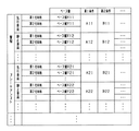
図3は、車両制御ECU10のROMに記憶されているデータ構造である。基準領域を設定するため基準条件であるベース値は、物標ごと、及び、安全装置の機能ごとに設けられている。このベース値は、図2で示した作動領域の幅(右方規制値XR及び左方規制値XL)及び奥行きLを定めたパラメータである。
FIG. 3 shows a data structure stored in the ROM of the
第1条件についての補正値は、物標ごと、及び安全装置の機能ごとに設けられている。この補正値は、作動領域の幅及び奥行き作動領域の幅(右方規制値XR及び左方規制値XL)及び奥行きLの少なくともいずれかを補正する負の値である。この第1条件は、上述した、自車両の走行状態において、直進状態でないと判定されることにより満たされるものである。すなわち、自車両が直進状態であれば、第1条件の補正値は用いられないが、自車両が直進状態でない(旋回状態である)場合には、第1条件の補正値がベース値に加算され、作動領域の幅(右方規制値XR及び左方規制値XL)及び奥行きLの少なくともいずれかが、ベース値に基づくものよりも小さくなる。 The correction value for the first condition is provided for each target and for each function of the safety device. The correction value is a negative value that corrects at least one of the width of the working area and the width of the working area (right limit value XR and left limit value XL) and the depth L. The first condition is satisfied by determining that the vehicle is not traveling straight in the traveling state of the host vehicle described above. That is, the correction value of the first condition is not used if the host vehicle is traveling straight, but the correction value of the first condition is added to the base value if the host vehicle is not traveling straight (turning). And at least one of the width (right limit value XR and left limit value XL) and the depth L of the operation area is smaller than that based on the base value.
第2条件についての補正値についても、第1条件と同様に、物標ごと、及び安全装置の機能ごとに設けられている。この第2条件は、上述した、自車両と物標との位置関係に基づいて満たされるものである。例えば、物標が自車両の右方向に位置すれば、条件が満たされ、第2条件の補正値がベース値に加算され、右方規制値XRがベース値に基づくものよりも大きくなる。これら補正条件を満たすか否かを判定する上で、領域設定部は補正判定手段として機能する。 Similarly to the first condition, the correction value for the second condition is provided for each target and for each function of the safety device. The second condition is satisfied based on the above-described positional relationship between the host vehicle and the target. For example, when the target is positioned to the right of the host vehicle, the condition is satisfied, the correction value of the second condition is added to the base value, and the rightward restriction value XR becomes larger than that based on the base value. The region setting unit functions as a correction determination unit in determining whether or not the correction condition is satisfied.
なお、条件の一例として、上述した第1条件と第2条件とを挙げたが、条件としてはこれらに限られることはなく、種々の条件を採用可能であり、その採用した条件の数だけ、補正値のデータ量は増加する。 In addition, although the 1st condition and the 2nd condition which were mentioned above were mentioned as an example of conditions, it is not restricted as these conditions, various conditions are employable, only the number of the adopted conditions, The amount of data of the correction value increases.
これらベース値や補正値を設定するうえで、この車両制御ECUを搭載した車両が利用される国や地域等に応じて、設定を変更する必要がある。このとき、第1補正値や第2補正値等の補正値を、それぞれの国や地域等に応じて設定すれば、そのデータ量は膨大なものとなる。 In setting the base value and the correction value, it is necessary to change the setting according to the country or region where the vehicle equipped with the vehicle control ECU is used. At this time, if correction values such as the first correction value and the second correction value are set according to each country or region, the amount of data becomes enormous.
そこで、第1補正値や第2補正値等の補正値についての、国や地域等に応じた設定を行うべく、仕向地に応じた補正値である仕向補正値を用いる。この仕向補正値について、図4に示す。仕向補正値は仕向地ごと、物標ごと、及び安全装置の機能ごとに設けられている。この仕向補正値は、ベース値を第1補正値や第2補正値などにより補正した後、全体に乗算される。また、仕向地によっては、安全装置の機能について、作動させる必要がない場合や、作動させるべきではない場合がある。この場合には、仕向補正値の値をゼロとして設定することで、作動領域の幅及び奥行きがゼロとなり、その安全装置を作動させなくすることができる。加えて、特定の物標について、特定の機能のみを作動させるべきではない場合についても、同様に、仕向補正値の値をゼロとして設定することで、その安全装置を作動させなくすることができる。 Therefore, in order to set the correction values such as the first correction value and the second correction value according to the country, the region, and the like, a destination correction value that is a correction value according to the destination is used. The destination correction value is shown in FIG. The destination correction value is provided for each destination, for each target, and for each function of the safety device. The destination correction value is multiplied by the whole after correcting the base value with the first correction value, the second correction value, and the like. Also, depending on the destination, the function of the safety device may or may not need to be activated. In this case, by setting the value of the destination correction value as zero, the width and depth of the operating area become zero, and the safety device can be disabled. In addition, even in the case where only a specific function should not be activated for a specific target, the safety device can be deactivated by setting the value of the destination correction value as zero as well. .
なお、この仕向地は、道路状況などが共通する複数の国や地域等をひとつの仕向地に対応付けており、車両において、使用される国や地域等が設定されれば、その国や地域等に対応付けられた仕向地が読み出されて用いられる。 In this case, a plurality of countries, areas, etc. with common road conditions are associated with one destination, and if the country, area, etc. used in the vehicle is set, the country or area is selected. The destination associated with the etc. is read and used.
自車両の進行方向前方に位置する物標が先行車両である場合、第1条件と第2条件とを満たしていれば、警報装置31の作動領域を算出するには、ベース値R11を基準条件とし、第1条件に基づく第1補正値であるA11、第2条件の補正値であるA11を加算する。そして、補正された作動領域に、第1仕向地において、物標が先行車両であり、機能が警報機のである場合の仕向補正値であるα11を係数として乗算することにより、作動領域を求める。したがって、物標が先行車両である場合には、警報機能の作動領域は、次式(1)により求められる。 If the target located ahead in the traveling direction of the host vehicle is a preceding vehicle, and if the first condition and the second condition are satisfied, the base value R11 is used as a reference condition to calculate the operation area of the alarm device 31 Then, A11 which is a first correction value based on the first condition and A11 which is a correction value of the second condition are added. Then, the working area is determined by multiplying the corrected working area by the factor α11, which is a destination correction value when the target is the preceding vehicle and the function is an alarm at the first destination. Therefore, when the target is a leading vehicle, the operation area of the alarm function is obtained by the following equation (1).
作動領域=(ベース値R11+A11+B11)×α11・・・(1)
この作動領域を設定し、安全装置を作動させるか否かを判定する一連の処理について、図5のフローチャートにより説明する。図5のフローチャートの処理は、自車両の進行方向前方に位置する各物標についてそれぞれ行われ、且つ、安全装置の機能ごとに行われる。
Operating area = (base value R11 + A11 + B11) × α11 (1)
A series of processes of setting the operation area and determining whether to activate the safety device will be described with reference to the flowchart of FIG. The process of the flowchart of FIG. 5 is performed for each target located in front of the traveling direction of the host vehicle, and is performed for each function of the safety device.
まず、物標の認識処理を行い、物標の種別を特定し(S101)、安全装置の機能、及び、物標の種別に応じたベース値を取得し、作動領域を設定する(S102)。続いて、走行状態の補正条件である第1条件を満たすか否かを判定する(S103)。第1条件を満たすと判定すれば(S103:YES)、作動領域を補正する(S104)。このとき、例えば、安全装置の機能が警報機能であり、物標が先行車両であれば、上述したとおり第1補正値であるA11により補正される。同様に、自車両と物標との位置関係の補正条件である第2条件を満たすか否かを判定する(S105)。第2条件を満たすと判定すれば(S105:YES)、作動領域を補正する(S106)。このとき、例えば、安全装置の機能が警報機能であり、物標が先行車両であれば、上述したとおり第2補正値であるA21により補正される。なお、第1条件を満たさない場合には(S103:NO)、S104の処理を実行せず、第2条件を満たさない場合には(S105:NO)、S106の処理を実行しない。 First, recognition processing of the target is performed, the type of the target is specified (S101), the base device corresponding to the function of the safety device and the type of the target is acquired, and the operation area is set (S102). Subsequently, it is determined whether the first condition which is the correction condition of the traveling state is satisfied (S103). If it is determined that the first condition is satisfied (S103: YES), the operation area is corrected (S104). At this time, for example, if the function of the safety device is an alarm function and the target is a leading vehicle, correction is performed by the first correction value A11 as described above. Similarly, it is determined whether the second condition, which is a correction condition of the positional relationship between the host vehicle and the target, is satisfied (S105). If it is determined that the second condition is satisfied (S105: YES), the operation area is corrected (S106). At this time, for example, if the function of the safety device is an alarm function and the target is a leading vehicle, correction is performed by the second correction value A21 as described above. When the first condition is not satisfied (S103: NO), the process of S104 is not performed. When the second condition is not satisfied (S105: NO), the process of S106 is not performed.
各条件に基づく補正が済めば、仕向地に基づいて作動領域を補正する。すなわち、物標の種別及び安全装置の機能に対応した仕向補正値を、作動領域に対して乗算することにより補正する(S107)。このようにして作動領域が設定されれば、物標が作動領域内に位置するか否かを判定する(S108)。物標が作動領域内に位置すると判定すれば(S108:108)、安全装置を作動させ(S109)、物標が作動領域内に位置しないと判定すれば(S108:NO)、そのまま一連の処理を終了する。 After correction based on each condition, the working area is corrected based on the destination. That is, the direction correction value corresponding to the type of the target and the function of the safety device is corrected by multiplying the operation area (S107). If the operation area is set in this way, it is determined whether the target is located within the operation area (S108). If it is determined that the target is located in the operation area (S108: 108), the safety device is operated (S109), and if it is determined that the target is not located in the operation area (S108: NO), a series of processing is performed as it is Finish.
上記構成により、本実施形態に係る車両制御装置は、以下の効果を奏する。 By the above configuration, the vehicle control device according to the present embodiment has the following effects.
・上記実施形態では、安全装置の機能ごと、及び、物標の種別ごとに、自車両の走行状態や自車両と物標との位置関係などの多岐にわたる補正条件に対して補正値を設定しているため、判定領域の細かな設定が可能であり、安全装置を精度良く作動させることができる。一方、多岐にわたる補正条件についての補正値を仕向地ごとに設けるものとすれば、データ量が増大する。本実施形態では、安全装置の機能ごと、及び物標の種別ごとに、各補正条件に対して補正値を設定し、且つ、安全装置の機能ごと、及び物標の種別ごとに仕向補正値も設定している。そして、判定領域をベース値に対して各補正条件に基づく補正を行った後、仕向補正値により補正している。これにより、補正条件に応じて、作動領域の細かな設定を可能としつつ、データ量の増大を抑制することができる。 In the above embodiment, correction values are set for various correction conditions such as the traveling state of the host vehicle and the positional relationship between the host vehicle and the target for each function of the safety device and for each type of target. Therefore, the judgment area can be finely set, and the safety device can be operated accurately. On the other hand, if correction values for various correction conditions are provided for each destination, the amount of data increases. In this embodiment, a correction value is set for each correction condition for each function of the safety device and each type of target, and a direction correction value is also set for each function of the safety device and each type of target It is set. Then, after the determination area is corrected based on each correction condition with respect to the base value, the correction is performed using the destination correction value. Thereby, according to the correction condition, it is possible to suppress an increase in the amount of data while enabling fine setting of the operation area.
・仕向地によっては、安全装置の機能や、安全装置を作動させる対象となる物標の種別によっては、安全装置を作動させる必要がない、若しくは安全装置を作動させるべきでない場合がある。上記構成では、安全装置の機能等について、作動させないものについては、仕向補正値をゼロとしている。したがって、簡易な方法で作動させない安全装置の機能を設定することができる。 Depending on the destination, depending on the function of the safety device or the type of target to which the safety device is to be activated, the safety device may not be required to be activated or should not be activated. In the above-described configuration, for the functions of the safety device, etc., the destination correction value is set to zero for those which are not operated. Therefore, it is possible to set the function of the safety device which is not activated in a simple manner.
・複数の国や地域等を纏めて仕向地としているため、データ量をより低減することができる。 ・ Since multiple countries, regions, etc. are combined to be destinations, the amount of data can be further reduced.
<第2実施形態>
本実施形態では、第1実施形態と全体構成は共通しており、処理の一部、及び、データ構造が異なっている。
Second Embodiment
In the present embodiment, the entire configuration is common to that of the first embodiment, and part of the processing and the data structure are different.
本実施形態では、安全装置を作動させるうえで、安全装置の各機能について、作動条件として作動タイミングを設定する。このとき、車両制御ECU10は、条件設定手段として機能する。加えて、自車両と物標との相対距離と、自車両と物標との相対速度又は相対加速度により、自車両と物標との相対距離がゼロとなるまでの時間である衝突予測時間を算出する。そして、衝突予測時間が作動タイミングへと到達すれば、その作動タイミングに対応する安全装置を作動させる。このとき、作動判定部14と制御処理部15とが協働して、作動判定手段として機能する。
In the present embodiment, when operating the safety device, the operation timing is set as the operation condition for each function of the safety device. At this time, the
図6は、車両制御ECU10のROMに記憶されているデータ構造である。作動タイミングの基準値を基準条件として定めるベース値は、安全装置の機能ごと、物標の種別ごと、および仕向地ごとに設定されている。また、この作動タイミングを補正する補正値は、安全装置の機能ごと、及び物標の種別ごとに設けられている。
FIG. 6 shows a data structure stored in the ROM of the
例えば、第1仕向地において、物標が先行車両であり、警報機能の作動タイミングを設定する際に、第1条件と第2条件が満たされていれば、第1ベース値であるX11に第1条件の補正値であるA11と第2条件の補正値であるB11を加算し、次式(2)により作動タイミングを設定する。なお、A11やB11等の補正値は、各補正条件によって、正の値も負の値もとり得る。 For example, in the first destination, when the target is the preceding vehicle and the first condition and the second condition are satisfied in setting the operation timing of the alarm function, the first base value X11 is set to the first base value The operation timing is set according to the following equation (2) by adding A11 which is the correction value of the one condition and B11 which is the correction value of the second condition. The correction values such as A11 and B11 can be positive or negative depending on each correction condition.
作動タイミング=(ベース値X11+A11+B11)・・・(2)
各ベース値は、自車両と物標との相対速度と、作動タイミングのマップにより設定されている。図7は、このベース値のマップの一例である。ベース値X11及びベース値Y11は、それぞれ、相対速度が所定値となれば大きくなり、所定の作動タイミングで一定の値をとる。一方、ベース値Z11は、相対速度に関わらず、作動タイミングは0秒である。すなわち、安全装置の機能について、このベース値Z11のような設定がなされているならば、その機能は作動しないこととなる。
Operation timing = (base value X11 + A11 + B11) ... (2)
Each base value is set by a map of the relative velocity between the host vehicle and the target and the operation timing. FIG. 7 is an example of this base value map. Each of the base value X11 and the base value Y11 increases as the relative velocity reaches a predetermined value, and takes a constant value at a predetermined operation timing. On the other hand, the base value Z11 has an operation timing of 0 seconds regardless of the relative speed. That is, if the function of the safety device is set like this base value Z11, that function will not operate.
この作動タイミングを設定し、安全装置を作動させるか否かを判定する一連の処理について、図8のフローチャートにより説明する。図8のフローチャートの処理は、自車両の進行方向前方に位置する各物標についてそれぞれ行われ、且つ、安全装置の機能ごとに行われる。 A series of processes of setting the operation timing and determining whether to activate the safety device will be described with reference to the flowchart of FIG. The process of the flowchart of FIG. 8 is performed for each target located in front of the traveling direction of the host vehicle, and is performed for each function of the safety device.
まず、物標の認識処理を行い、物標の種別を特定し(S201)、安全装置の機能、物標の種別、及び仕向地に応じたベース値を取得し、作動タイミングを設定する(S202)。続いて、補正条件を満たしたか否かを判定する(S203)。作動タイミングの補正条件を満たしたと判定すれば(S203:YES)、その補正値により作動タイミングを設定する(S204)。一方、作動タイミングの補正条件を満たしていなければ(203:NO)、S204の処理を行うことはない。 First, recognition processing of the target is performed, the type of target is specified (S201), the base device according to the function of the safety device, the type of target, and the destination is acquired, and the operation timing is set (S202) ). Subsequently, it is determined whether the correction condition is satisfied (S203). If it is determined that the correction condition of the operation timing is satisfied (S203: YES), the operation timing is set by the correction value (S204). On the other hand, if the correction condition of the operation timing is not satisfied (203: NO), the process of S204 is not performed.
このようにして作動タイミングが求まれば、衝突予測時間を算出し(S205)、衝突予測時間と作動タイミングとを比較する(S206)。衝突予測時間が作動タイミング以下であれば(S206:YES)、衝突予測時間が作動タイミングに到達したことを意味するため、安全装置を作動させる(S207)。一方、衝突予測時間が作動タイミングよりも大きければ(S206:NO)、そのまま一連の処理を終了する。 Once the actuation timing is determined in this way, the collision prediction time is calculated (S205), and the collision prediction time is compared with the actuation timing (S206). If the collision prediction time is less than the actuation timing (S206: YES), it means that the collision prediction time has reached the actuation timing, and the safety device is activated (S207). On the other hand, if the collision prediction time is greater than the actuation timing (S206: NO), the series of processing is ended.
上記構成により、本実施形態に係る車両制御装置は、第1実施形態に係る車両制御装置が奏する効果に加えて、以下の効果を奏する。 With the above configuration, the vehicle control device according to the present embodiment exhibits the following effects in addition to the effects exhibited by the vehicle control device according to the first embodiment.
・作動タイミングの基準値を定めるベース値を仕向地ごとに設定しているため、各補正条件について、仕向地ごとに補正値を設定する必要がなく、データ量を低減することができる。 Since the base value for determining the reference value of the operation timing is set for each destination, there is no need to set a correction value for each destination for each correction condition, and the amount of data can be reduced.
<第3実施形態>
第1実施形態では、上述した通り、右方規制値XR及び左方規制値XLに基づく判定領域を自車両40の進行方向前方に設定している。そして、その判定領域に物標60が存在するか否かによって、衝突の危険性があるか否かを判定している。この点、本実施形態では、物標60の移動軌跡を予測し、自車両40と衝突すると予測される位置である衝突横位置62を求める。そして、その衝突横位置62が、右方規制値XR及び左方規制値XLにより規定される範囲内に位置するか否かを判定することにより、衝突の可能性があるか否かを判定している。
Third Embodiment
In the first embodiment, as described above, the determination region based on the rightward regulation value XR and the leftward regulation value XL is set forward of the
図9に、作動判定部14が行う判定方法の概要を示す。右方規制値XR及び左方規制値XLは、第1実施形態と同様に求められるものであるため、その説明を省略する。物標60の過去位置61は、所定期間に亘って位置履歴として記憶され、その過去位置61と、物標60の現在位置とから、物標60の移動軌跡を推定する。この移動軌跡に沿って物標60が移動すると仮定し、自車両40の前端と物標60との縦位置がゼロとなる点の横位置を、衝突横位置62として求める。
The outline | summary of the determination method which the operation | movement determination part 14 performs in FIG. 9 is shown. The rightward regulation value XR and the leftward regulation value XL are obtained in the same manner as in the first embodiment, and thus the description thereof is omitted. The
衝突横位置62は、右方規制値XR及び左方規制値XLと、それぞれ比較される。そして、衝突横位置62が、右方規制値XR及び左方規制値XLにより規定される範囲内に位置していれば、自車両40が物標60と衝突する可能性があると判定する。
The
ところで、物標60が右方に存在している場合においても、物標60の移動履歴によっては、衝突横位置62が左方に求められることがある。そのため、自車両40と物標60との位置関係についての補正条件について、衝突横位置62の位置に応じた補正条件としてもよい。
By the way, even when the
なお、本実施形態において、安全装置の作動タイミングは、第1実施形態のごとく、奥行きを有する作動領域を設定し、その奥行き内に位置するか否かを判定するものとしてもよいし、第2実施形態のごとく、作動タイミングと衝突予測時間とを比較するものとしてもよい。 In the present embodiment, as in the first embodiment, the operation timing of the safety device may set an operation area having a depth and determine whether or not the position is within the depth. As in the embodiment, the operation timing and the collision prediction time may be compared.
上記構成により、本実施形態に係る車両制御装置は、第1実施形態の車両制御装置が奏する効果に準ずる効果を奏する。 With the above-described configuration, the vehicle control device according to the present embodiment has an effect according to the effect exhibited by the vehicle control device of the first embodiment.
<第4実施形態>
本実施形態に係る車両制御装置は、全体構成は第2実施形態と共通しており、処理が一部異なっている。
Fourth Embodiment
The overall configuration of the vehicle control device according to the present embodiment is the same as that of the second embodiment, and the processing is partially different.
第2実施形態では、ベース値を自車両と物標との相対速度のマップとしているが、本実施形態では、物標が、自車両40の進行方向前方を自車両40と同方向に走行する先行車両60である場合に、ベース値を、自車両40と先行車両60とのラップ率Laのマップとしている。このラップ率Laは、自車両40と先行車両60との幅が重複する割合であるラップ率Laを算出する。このラップ率Laについて、図10を用いて説明する。自車両40の幅をXwとし、自車両40の幅と先行車両60の幅とが重複する領域の幅をXlとすると、ラップ率Laは、次式(1)で求められる。
In the second embodiment, although the base value is a map of the relative velocity between the host vehicle and the target, in the present embodiment, the target travels in the same direction as the
La=Xl/Xw・・・(1)
したがって、ラップ率Laが大きいほど、自車両40の幅と先行車両60の幅とが重複しているため、先行車両60において急制動等が行われた場合に、衝突の回避が困難であるといえる。一方、ラップ率Laが小さいほど、自車両40の幅と先行車両60の幅とが重複していないため、先行車両60において急制動等が行われた場合に、衝突の回避が容易であるといえる。そこで、ラップ率Laが小さいほど、作動タイミングが小さくなり、ラップ率Laが大きいほど、作動タイミングが大きくなるようなベース値を設定する。
La = Xl / Xw (1)
Therefore, as the lap rate La is larger, the width of the
上記構成により、本実施形態に係る車両制御装置は、第2実施形態に準ずる効果を奏する。 With the above-described configuration, the vehicle control device according to the present embodiment has an effect according to the second embodiment.
<変形例>
・第1実施形態では、ベース値に対して補正値を加減算したうえで、仕向補正値を乗算することにより、作動領域を求めているが、第2実施形態のごとく、ベース値を仕向地ごとに設定するものとしてもよい。
<Modification>
In the first embodiment, the working area is determined by multiplying the base value by the correction value and then multiplying the correction value by the destination correction value. However, as in the second embodiment, the base value is calculated for each destination. It may be set to
・第2実施形態では、ベース値を仕向地ごとに設けているが、第1実施形態のごとく、ベース値に対して補正値を加減算したうえで、仕向補正値を乗算することにより、作動タイミングを求めるものとしてもよい。 In the second embodiment, the base value is provided for each destination, but as in the first embodiment, the correction value is added to or subtracted from the base value, and then the operation correction timing is multiplied by the operation correction timing. You may ask for
・第1実施形態では、作動領域の奥行きを設定し、その作動領域内に物標が位置するか否かに応じて安全装置を作動させているが、第2実施形態のごとく、作動タイミングを算出するものとしてもよい。 In the first embodiment, the depth of the operation area is set, and the safety device is operated according to whether or not the target is positioned in the operation area. However, as in the second embodiment, the operation timing is It may be calculated.
・第2実施形態では、作動タイミングを仕向地に応じて設定するものとしているが、第1実施形態と同様に、右方規制値XR及び左方規制値XLも設定するものとし、これら右方規制値XR及び左方規制値XLも仕向地に応じて設定するものとしてもよい。 In the second embodiment, the operation timing is set in accordance with the destination, but as in the first embodiment, the rightward regulation value XR and the leftward regulation value XL are also set, and these rightward regulation values are also set. The control value XR and the left control value XL may be set according to the destination.
・第2実施形態では、ベース値を相対速度のマップとしており、第4実施形態では、ベース値をラップ率Laのマップとしている。この点、ベース値を、自車両の進行方向に直交する方向についての物標の相対位置である横位置に対するマップとしてもよい。この場合には横位置が自車両の進行方向から離れるほど衝突の回避は容易であるため、ベース値を小さくするものとすればよい。 In the second embodiment, the base value is a map of the relative velocity, and in the fourth embodiment, the base value is a map of the lap rate La. In this respect, the base value may be a map for the lateral position which is the relative position of the target in the direction orthogonal to the traveling direction of the host vehicle. In this case, as the lateral position is more distant from the traveling direction of the host vehicle, the collision can be avoided more easily, so the base value may be reduced.
・第2実施形態では、ベース値を相対速度のマップとしており、第4実施形態では、ベース値をラップ率Laのマップとしている。この点、ベース値を相対速度及びラップ率Laに応じて変化するマップとしてもよい。また、上述した横位置に対するマップとしてもよい。横位置に対するマップとした場合、その横位置が自車両の進行方向に近いほど、衝突の回避が困難であるため、作動タイミングを大きく設定し、安全装置が早く作動するようにすればよい。 In the second embodiment, the base value is a map of the relative velocity, and in the fourth embodiment, the base value is a map of the lap rate La. In this regard, the base value may be a map that changes in accordance with the relative velocity and the lap rate La. Moreover, it is good also as a map with respect to the horizontal position mentioned above. In the case of a map for the lateral position, as the lateral position is closer to the traveling direction of the host vehicle, it is more difficult to avoid a collision, so the actuation timing may be set larger and the safety device may be actuated earlier.
・第3実施形態では、第1実施形態の処理の代わりに衝突横位置を用いるものとしたが、第1実施形態の、横位置を用いる処理と並行して行うものとしてもよい。この場合、右方規制値XR及び左方規制値XLは、横位置を用いる処理、及び衝突横位置を用いる処理について、異なる値を算出するようにすればよい。すなわち、図3及び4で示したデータ構造を、横位置を用いる処理、及び衝突横位置を用いる処理について、それぞれ設けるものとすればよい。 In the third embodiment, the collision lateral position is used instead of the process of the first embodiment. However, the process may be performed in parallel with the process of using the lateral position according to the first embodiment. In this case, different values may be calculated for the rightward regulation value XR and the leftward regulation value XL for the process using the lateral position and the process using the collision lateral position. That is, the data structures shown in FIGS. 3 and 4 may be respectively provided for the process using the lateral position and the process using the collision lateral position.
・上記実施形態では、車両の前方に存在する障害物に対して衝突を回避するものとしているが、これに限定されるものではなく、車両の後方に存在する障害物を検出するようにして、その障害物に対して衝突を回避するシステムに適用しても良い。また、車両に対して接近してくるような障害物に対して衝突を回避するシステムに適用してもよい。なお、進行方向前方とは、車両が前進している場合には車両の前方のことを意味するが、車両が後退している場合には車両の後方ことを意味する。 In the above embodiment, a collision is avoided with respect to an obstacle present in front of the vehicle, but the present invention is not limited to this, and an obstacle present in the rear of the vehicle is detected, The present invention may be applied to a system for avoiding a collision against the obstacle. Further, the present invention may be applied to a system for avoiding a collision against an obstacle approaching to a vehicle. The forward traveling direction means the front of the vehicle when the vehicle is moving forward, but means the rear of the vehicle when the vehicle is moving backward.
・各実施形態では、安全装置として警報装置31及びブレーキ装置32を挙げたが、安全装置はこれらに限られることはない。例えば、操舵装置を制御することにより、衝突を回避するものとしてもよい。 -In each embodiment, although alarm device 31 and brake device 32 were mentioned as a safety device, a safety device is not restricted to these. For example, a collision may be avoided by controlling the steering device.
・上記実施形態では、運転者により車両が運転されるものとしているが、ECUにより自動的に運転されるものに対しても同様に適用可能である。 In the above embodiment, the vehicle is driven by the driver. However, the present invention is similarly applicable to one that is automatically driven by the ECU.
10…車両制御ECU。 10: Vehicle control ECU.
Claims (15)
前記安全装置を作動させる条件である作動条件のベースとなる基準条件を、各一般補正値により補正するための各条件であって、前記自車両が使用される国や地域等である仕向地に関係なく、前記自車両又は前記物標の状態が所定状態であることにより満たされる複数の補正条件が、それぞれ満たされているか否かを判定する補正判定手段と、
前記基準条件を、前記補正判定手段により満たされていると判定された補正条件に係る前記一般補正値に基づいて補正したうえで、前記仕向地ごとに定められた補正値である仕向補正値により補正することにより、前記作動条件を設定する条件設定手段と、
前記条件設定手段により設定された前記作動条件に基づいて、前記安全装置を作動させるか否かを判定する作動判定手段と、
を備えることを特徴とする、車両制御装置。 Vehicle control device that operates as a safety device a device for avoiding collision or reducing collision damage between the own vehicle and the target when the risk of the own vehicle colliding with the target existing around the own vehicle increases (10) and
It is each condition for correcting the standard condition which becomes the basis of the operating condition which is a condition which operates the safety device by each general correction value, and is a destination where the vehicle is used, such as a country or a region regardless, a plurality of correction conditions, determines correction determination means for determining whether being their respective was fully filled by said vehicle or said target object state is predetermined state,
The reference condition, after corrected based on the general correction value according to correction conditions is determined to be met by the correction determining unit, by destination correction value is a correction value defined for each of the destination Condition setting means for setting the operating condition by correction ;
Operation determination means for determining whether or not to operate the safety device based on the operation condition set by the condition setting means;
A vehicle control apparatus comprising:
前記仕向補正値は、前記仕向地ごとに加えて、前記種別ごとに定められていることを特徴とする、請求項1に記載の車両制御装置。 It further comprises type determination means for determining the type of the target,
The vehicle control device according to claim 1, wherein the destination correction value is determined for each of the types in addition to each of the destinations.
前記仕向補正値は、前記仕向地ごとに加えて、前記安全装置の前記機能ごとに定められていることを特徴とする、請求項1又は2に記載の車両制御装置。 The safety device has multiple functions,
The vehicle control device according to claim 1 or 2, wherein the destination correction value is determined for each function of the safety device in addition to each destination.
前記仕向地について、前記安全装置を作動させない場合には、前記係数としてゼロが設定されていることを特徴とする、請求項1〜3のいずれか1項に記載の車両制御装置。 The destination correction value is a predetermined coefficient to be multiplied after correcting the reference condition based on the correction condition,
The vehicle control device according to any one of claims 1 to 3, wherein the coefficient is set to zero when the safety device is not operated for the destination.
前記安全装置を作動させる条件である作動条件のベースとなる条件であって、前記自車両が使用される国や地域等である仕向地ごとに定められている基準条件を、各補正値により補正するための各条件であって、前記仕向地に関係なく、前記自車両又は前記物標の状態が所定状態であることにより満たされる複数の補正条件が、それぞれ満たされているか否かを判定する補正判定手段と、
前記基準条件を、前記補正判定手段により満たされていると判定された補正条件に係る前記補正値に基づいて補正することにより、前記作動条件を設定する条件設定手段と、
前記条件設定手段により設定された前記作動条件に基づいて、前記安全装置を作動させるか否かを判定する作動判定手段と、
を備えることを特徴とする、車両制御装置。 Vehicle control device that operates as a safety device a device for avoiding collision or reducing collision damage between the own vehicle and the target when the risk of the own vehicle colliding with the target existing around the own vehicle increases (10) and
Each correction value corrects a reference condition that is a condition for operating the safety device, which is a base of the operating condition , and is set for each destination, such as a country or a region where the vehicle is used. a respective conditions for, whether or not regardless of the destination, the of the vehicle or the target object state plurality of correction conditions that are satisfied by a predetermined state, being their respective been fully Correction determination means for determining
The reference condition, by correcting on the basis of the correction value in accordance with the meet has been has been judged correction conditions by the correction determination means, and condition setting means for setting the operating conditions,
Operation determination means for determining whether or not to operate the safety device based on the operation condition set by the condition setting means;
A vehicle control apparatus comprising:
前記基準条件は、前記仕向地ごとに加えて、前記種別ごとに定められていることを特徴とする、請求項4に記載の車両制御装置。 It further comprises type determination means for determining the type of the target,
The vehicle control device according to claim 4, wherein the reference condition is determined for each of the types in addition to each of the destinations.
前記基準条件は、前記仕向地ごとに加えて、前記安全装置の前記機能ごとに定められていることを特徴とする、請求項4又は5に記載の車両制御装置。 The safety device has multiple functions,
The vehicle control device according to claim 4 or 5, wherein the reference condition is determined for each function of the safety device in addition to each destination.
前記仕向地について、前記安全装置を作動させない場合には、前記基準条件としてゼロが設定されていることを特徴とする、請求項5〜7のいずれか1項に記載の車両制御装置。 The reference condition is represented by a numerical value,
The vehicle control device according to any one of claims 5 to 7, wherein zero is set as the reference condition when the safety device is not operated for the destination.
前記判定手段は、前記物標の自車両に対する相対位置が前記判定領域内に位置することを条件に、前記安全装置を作動させることを特徴とする、請求項1〜8のいずれか1項に記載の車両制御装置。 The condition setting means sets, as the operation condition, a determination area having a predetermined width in the forward direction of the host vehicle,
The said determination means operates the said safety device on the condition that the relative position with respect to the own vehicle of the said target is located in the said determination area | region, It is characterized by the above-mentioned. Vehicle control device as described.
前記判定手段は、前記物標の自車両に対する相対位置と前記作動タイミングとに基づいて、前記安全装置を作動させることを特徴とする、請求項1〜10のいずれか1項に記載の車両制御装置。 The condition setting means sets an operation timing for operating the safety device as the operation condition,
The vehicle control according to any one of claims 1 to 10, wherein the determination means operates the safety device based on the relative position of the target relative to the vehicle and the operation timing. apparatus.
前記安全装置を作動させる条件である作動条件のベースとなる基準条件を、各一般補正値により補正するための各条件であって、前記自車両が使用される国や地域等である仕向地に関係なく、前記自車両又は前記物標の状態が所定状態であることにより満たされる複数の補正条件が、それぞれ満たされているか否かを判定する補正判定ステップと、
前記基準条件を、前記補正判定ステップで満たされていると判定された補正条件に係る前記一般補正値に基づいて補正したうえで、前記仕向地ごとに定められた補正値である仕向補正値により補正することにより、前記作動条件を設定する条件設定ステップと、
前記条件設定ステップで設定された前記作動条件に基づいて、前記安全装置を作動させるか否かを判定する作動判定ステップと、
を実行することを特徴とする、車両制御方法。 Vehicle control device that operates as a safety device a device for avoiding collision or reducing collision damage between the own vehicle and the target when the risk of the own vehicle colliding with the target existing around the own vehicle increases A vehicle control method performed by (10), wherein
It is each condition for correcting the standard condition which becomes the basis of the operating condition which is a condition which operates the safety device by each general correction value, and is a destination where the vehicle is used, such as a country or a region regardless, the plurality of correction conditions, a correction determination step of determining whether their respective been was fully filled by said vehicle or said target object state is predetermined state,
The reference condition, after corrected based on the correction determining the general correction value according to reach has been has been judged correction condition in the step, the destination correction value is a correction value defined for each of the destination A condition setting step of setting the operating condition by correction ;
An operation determining step of determining whether to operate the safety device based on the operating condition set in the condition setting step;
A vehicle control method characterized in that:
前記安全装置を作動させる条件である作動条件のベースとなる条件であって、前記自車両が使用される国や地域等である仕向地ごとに定められている基準条件を、各補正値により補正するための各条件であって、前記仕向地に関係なく、前記自車両又は前記物標の状態が所定状態であることにより満たされる複数の補正条件が、それぞれ満たされているか否かを判定する補正判定ステップと、
前記基準条件を、前記補正判定ステップで満たされていると判定された補正条件に係る前記補正値に基づいて補正することにより、前記作動条件を設定する条件設定ステップと、
前記条件設定ステップで設定された前記作動条件に基づいて、前記安全装置を作動させるか否かを判定する作動判定ステップと、
を実行することを特徴とする、車両制御方法。 Vehicle control device that operates as a safety device a device for avoiding collision or reducing collision damage between the own vehicle and the target when the risk of the own vehicle colliding with the target existing around the own vehicle increases A vehicle control method performed by (10), wherein
Each correction value corrects a reference condition that is a condition for operating the safety device, which is a base of the operating condition , and is set for each destination, such as a country or a region where the vehicle is used. a respective conditions for, whether or not regardless of the destination, the of the vehicle or the target object state plurality of correction conditions that are satisfied by a predetermined state, being their respective been fully A correction determination step of determining
The reference condition, by correcting on the basis of the correction value according to the correction determination correction condition is determined to be satisfied in step, a condition setting step of setting the operating conditions,
An operation determining step of determining whether to operate the safety device based on the operating condition set in the condition setting step;
A vehicle control method characterized in that:
Priority Applications (5)
| Application Number | Priority Date | Filing Date | Title |
|---|---|---|---|
| JP2015072923A JP6535194B2 (en) | 2015-03-31 | 2015-03-31 | Vehicle control device and vehicle control method |
| DE112016001541.0T DE112016001541T5 (en) | 2015-03-31 | 2016-03-24 | VEHICLE CONTROL DEVICE AND VEHICLE CONTROL PROCEDURE |
| US15/562,225 US10861337B2 (en) | 2015-03-31 | 2016-03-24 | Vehicle control apparatus and vehicle control method |
| CN201680019385.3A CN107408346B (en) | 2015-03-31 | 2016-03-24 | Vehicle control device and vehicle control method |
| PCT/JP2016/059294 WO2016158634A1 (en) | 2015-03-31 | 2016-03-24 | Vehicle control device and vehicle control method |
Applications Claiming Priority (1)
| Application Number | Priority Date | Filing Date | Title |
|---|---|---|---|
| JP2015072923A JP6535194B2 (en) | 2015-03-31 | 2015-03-31 | Vehicle control device and vehicle control method |
Publications (3)
| Publication Number | Publication Date |
|---|---|
| JP2016192167A JP2016192167A (en) | 2016-11-10 |
| JP2016192167A5 JP2016192167A5 (en) | 2017-03-30 |
| JP6535194B2 true JP6535194B2 (en) | 2019-06-26 |
Family
ID=57006793
Family Applications (1)
| Application Number | Title | Priority Date | Filing Date |
|---|---|---|---|
| JP2015072923A Active JP6535194B2 (en) | 2015-03-31 | 2015-03-31 | Vehicle control device and vehicle control method |
Country Status (5)
| Country | Link |
|---|---|
| US (1) | US10861337B2 (en) |
| JP (1) | JP6535194B2 (en) |
| CN (1) | CN107408346B (en) |
| DE (1) | DE112016001541T5 (en) |
| WO (1) | WO2016158634A1 (en) |
Families Citing this family (9)
| Publication number | Priority date | Publication date | Assignee | Title |
|---|---|---|---|---|
| US9215124B2 (en) | 2010-11-03 | 2015-12-15 | Broadcom Corporation | Unified vehicle network frame protocol |
| JP6412457B2 (en) * | 2015-03-31 | 2018-10-24 | 株式会社デンソー | Driving support device and driving support method |
| DE102016224913A1 (en) | 2016-12-14 | 2018-06-14 | Robert Bosch Gmbh | Method for automatically setting the speed of a motorcycle |
| JP6638172B2 (en) * | 2017-10-04 | 2020-01-29 | 本田技研工業株式会社 | Vehicle control device, vehicle control method, and program |
| KR101928895B1 (en) * | 2018-10-10 | 2018-12-13 | 대신네트웍스 주식회사 | System of recognizing object and warning by microwave frequency analysis |
| KR101929806B1 (en) * | 2018-10-10 | 2018-12-17 | 대신네트웍스 주식회사 | System of recognizing pedestrian and warning in bad weather |
| JP2020090204A (en) * | 2018-12-06 | 2020-06-11 | ロベルト・ボッシュ・ゲゼルシャフト・ミト・ベシュレンクテル・ハフツングRobert Bosch Gmbh | Processing device and processing method for rider protection system of saddle-riding type vehicle, rider protection system of saddle-riding type vehicle and saddle-riding type vehicle |
| US11091132B2 (en) * | 2019-04-12 | 2021-08-17 | Bendix Commercial Vehicle Systems, Llc | Delay autonomous braking activation due to potential forward turning vehicle |
| DE112020004692T5 (en) * | 2019-09-30 | 2022-06-23 | Honda Motor Co., Ltd. | SIDE RIDE VEHICLE |
Family Cites Families (17)
| Publication number | Priority date | Publication date | Assignee | Title |
|---|---|---|---|---|
| JPH10267695A (en) | 1997-03-25 | 1998-10-09 | Harness Sogo Gijutsu Kenkyusho:Kk | Display device for vehicle |
| JP2007137126A (en) * | 2005-11-15 | 2007-06-07 | Mazda Motor Corp | Obstacle detecting device for vehicle |
| DE102006052481A1 (en) * | 2006-11-07 | 2008-05-08 | Robert Bosch Gmbh | Method and device for operating a vehicle with at least one driver assistance system |
| JP5180641B2 (en) * | 2008-03-25 | 2013-04-10 | 富士重工業株式会社 | Vehicle driving support device |
| JP2010018230A (en) * | 2008-07-14 | 2010-01-28 | Toyota Motor Corp | Occupant crash protection device and method for changing operating condition |
| CN102171743B (en) | 2008-10-02 | 2014-08-20 | 日立汽车系统株式会社 | Information processing device associated with vehicle traveling |
| JP2010097480A (en) * | 2008-10-17 | 2010-04-30 | Toyota Motor Corp | Safe driving promotion system |
| DE102009016580A1 (en) * | 2009-04-06 | 2010-10-07 | Hella Kgaa Hueck & Co. | Data processing system and method for providing at least one driver assistance function |
| EP2289754B1 (en) * | 2009-08-31 | 2015-04-29 | Toyota Motor Europe NV/SA | Vehicle or traffic control method and system |
| EP2306433A1 (en) * | 2009-10-05 | 2011-04-06 | Nederlandse Organisatie voor toegepast -natuurwetenschappelijk onderzoek TNO | Collision avoidance system and method for a road vehicle and respective computer program product |
| US9216740B2 (en) * | 2010-06-15 | 2015-12-22 | Toyota Jidosha Kabushiki Kaisha | Driving support system |
| JP5510255B2 (en) * | 2010-10-01 | 2014-06-04 | トヨタ自動車株式会社 | Vehicle operation state determination system |
| JP5622104B2 (en) | 2010-12-24 | 2014-11-12 | トヨタ自動車株式会社 | Driving assistance device |
| JP2012234409A (en) * | 2011-05-02 | 2012-11-29 | Mazda Motor Corp | Driving support device for vehicle |
| EP2743899B1 (en) * | 2011-08-10 | 2018-02-14 | Toyota Jidosha Kabushiki Kaisha | Driving assistance device |
| DE102011083013A1 (en) * | 2011-09-20 | 2013-03-21 | Robert Bosch Gmbh | Method for operating driver assistance system in motor vehicle, involves calculating earliest and latest possible points in time to begin coasting and to start braking operation, for determining desired timepoint for slowing vehicle |
| JP5842863B2 (en) | 2013-05-14 | 2016-01-13 | 株式会社デンソー | Collision mitigation device |
-
2015
- 2015-03-31 JP JP2015072923A patent/JP6535194B2/en active Active
-
2016
- 2016-03-24 CN CN201680019385.3A patent/CN107408346B/en active Active
- 2016-03-24 US US15/562,225 patent/US10861337B2/en active Active
- 2016-03-24 WO PCT/JP2016/059294 patent/WO2016158634A1/en active Application Filing
- 2016-03-24 DE DE112016001541.0T patent/DE112016001541T5/en active Pending
Also Published As
| Publication number | Publication date |
|---|---|
| WO2016158634A1 (en) | 2016-10-06 |
| CN107408346B (en) | 2020-06-26 |
| JP2016192167A (en) | 2016-11-10 |
| CN107408346A (en) | 2017-11-28 |
| US10861337B2 (en) | 2020-12-08 |
| DE112016001541T5 (en) | 2017-12-21 |
| US20180122242A1 (en) | 2018-05-03 |
Similar Documents
| Publication | Publication Date | Title |
|---|---|---|
| JP6535194B2 (en) | Vehicle control device and vehicle control method | |
| JP6561584B2 (en) | Vehicle control apparatus and vehicle control method | |
| JP6581379B2 (en) | Vehicle control apparatus and vehicle control method | |
| JP6432447B2 (en) | Vehicle control apparatus and vehicle control method | |
| JP6453695B2 (en) | Driving support device and driving support method | |
| CN108541325B (en) | Driving support device and driving support method | |
| WO2016158944A1 (en) | Vehicle control device and vehicle control method | |
| JP6412457B2 (en) | Driving support device and driving support method | |
| CN109204311B (en) | Automobile speed control method and device | |
| JP6592266B2 (en) | Object detection apparatus and object detection method | |
| JP4531621B2 (en) | Vehicle travel safety device | |
| JP6729282B2 (en) | Vehicle control device | |
| JP6504042B2 (en) | Control device, control method | |
| US9470790B2 (en) | Collision determination device and collision determination method | |
| WO2017111135A1 (en) | Travel assistance device and travel assistance method | |
| JP2019114030A (en) | Collision determination device | |
| WO2017065212A1 (en) | Vehicle control device and vehicle control method | |
| JP6358017B2 (en) | Driving assistance device | |
| JP6504078B2 (en) | Collision prediction device | |
| JP6432538B2 (en) | Collision prediction device | |
| EP2894618A1 (en) | Speed calculating device and speed calculating method, and collision determination device | |
| JP6733616B2 (en) | Vehicle control device |
Legal Events
| Date | Code | Title | Description |
|---|---|---|---|
| A521 | Request for written amendment filed |
Free format text: JAPANESE INTERMEDIATE CODE: A523 Effective date: 20170223 |
|
| A621 | Written request for application examination |
Free format text: JAPANESE INTERMEDIATE CODE: A621 Effective date: 20171019 |
|
| A131 | Notification of reasons for refusal |
Free format text: JAPANESE INTERMEDIATE CODE: A131 Effective date: 20180905 |
|
| A521 | Request for written amendment filed |
Free format text: JAPANESE INTERMEDIATE CODE: A523 Effective date: 20181101 |
|
| TRDD | Decision of grant or rejection written | ||
| A01 | Written decision to grant a patent or to grant a registration (utility model) |
Free format text: JAPANESE INTERMEDIATE CODE: A01 Effective date: 20190507 |
|
| A61 | First payment of annual fees (during grant procedure) |
Free format text: JAPANESE INTERMEDIATE CODE: A61 Effective date: 20190531 |
|
| R150 | Certificate of patent or registration of utility model |
Ref document number: 6535194 Country of ref document: JP Free format text: JAPANESE INTERMEDIATE CODE: R150 |
|
| R250 | Receipt of annual fees |
Free format text: JAPANESE INTERMEDIATE CODE: R250 |
|
| R250 | Receipt of annual fees |
Free format text: JAPANESE INTERMEDIATE CODE: R250 |
|
| R250 | Receipt of annual fees |
Free format text: JAPANESE INTERMEDIATE CODE: R250 |