WO2013022073A1 - 電子機器 - Google Patents
電子機器 Download PDFInfo
- Publication number
- WO2013022073A1 WO2013022073A1 PCT/JP2012/070383 JP2012070383W WO2013022073A1 WO 2013022073 A1 WO2013022073 A1 WO 2013022073A1 JP 2012070383 W JP2012070383 W JP 2012070383W WO 2013022073 A1 WO2013022073 A1 WO 2013022073A1
- Authority
- WO
- WIPO (PCT)
- Prior art keywords
- housing
- camera
- posture
- electronic device
- user
- Prior art date
- Legal status (The legal status is an assumption and is not a legal conclusion. Google has not performed a legal analysis and makes no representation as to the accuracy of the status listed.)
- Ceased
Links
Images






Classifications
-
- G—PHYSICS
- G03—PHOTOGRAPHY; CINEMATOGRAPHY; ANALOGOUS TECHNIQUES USING WAVES OTHER THAN OPTICAL WAVES; ELECTROGRAPHY; HOLOGRAPHY
- G03B—APPARATUS OR ARRANGEMENTS FOR TAKING PHOTOGRAPHS OR FOR PROJECTING OR VIEWING THEM; APPARATUS OR ARRANGEMENTS EMPLOYING ANALOGOUS TECHNIQUES USING WAVES OTHER THAN OPTICAL WAVES; ACCESSORIES THEREFOR
- G03B15/00—Special procedures for taking photographs; Apparatus therefor
-
- G—PHYSICS
- G03—PHOTOGRAPHY; CINEMATOGRAPHY; ANALOGOUS TECHNIQUES USING WAVES OTHER THAN OPTICAL WAVES; ELECTROGRAPHY; HOLOGRAPHY
- G03B—APPARATUS OR ARRANGEMENTS FOR TAKING PHOTOGRAPHS OR FOR PROJECTING OR VIEWING THEM; APPARATUS OR ARRANGEMENTS EMPLOYING ANALOGOUS TECHNIQUES USING WAVES OTHER THAN OPTICAL WAVES; ACCESSORIES THEREFOR
- G03B17/00—Details of cameras or camera bodies; Accessories therefor
- G03B17/02—Bodies
-
- G—PHYSICS
- G03—PHOTOGRAPHY; CINEMATOGRAPHY; ANALOGOUS TECHNIQUES USING WAVES OTHER THAN OPTICAL WAVES; ELECTROGRAPHY; HOLOGRAPHY
- G03B—APPARATUS OR ARRANGEMENTS FOR TAKING PHOTOGRAPHS OR FOR PROJECTING OR VIEWING THEM; APPARATUS OR ARRANGEMENTS EMPLOYING ANALOGOUS TECHNIQUES USING WAVES OTHER THAN OPTICAL WAVES; ACCESSORIES THEREFOR
- G03B17/00—Details of cameras or camera bodies; Accessories therefor
- G03B17/38—Releasing-devices separate from shutter
-
- G—PHYSICS
- G06—COMPUTING OR CALCULATING; COUNTING
- G06F—ELECTRIC DIGITAL DATA PROCESSING
- G06F3/00—Input arrangements for transferring data to be processed into a form capable of being handled by the computer; Output arrangements for transferring data from processing unit to output unit, e.g. interface arrangements
- G06F3/01—Input arrangements or combined input and output arrangements for interaction between user and computer
- G06F3/03—Arrangements for converting the position or the displacement of a member into a coded form
- G06F3/041—Digitisers, e.g. for touch screens or touch pads, characterised by the transducing means
-
- G—PHYSICS
- G03—PHOTOGRAPHY; CINEMATOGRAPHY; ANALOGOUS TECHNIQUES USING WAVES OTHER THAN OPTICAL WAVES; ELECTROGRAPHY; HOLOGRAPHY
- G03B—APPARATUS OR ARRANGEMENTS FOR TAKING PHOTOGRAPHS OR FOR PROJECTING OR VIEWING THEM; APPARATUS OR ARRANGEMENTS EMPLOYING ANALOGOUS TECHNIQUES USING WAVES OTHER THAN OPTICAL WAVES; ACCESSORIES THEREFOR
- G03B2217/00—Details of cameras or camera bodies; Accessories therefor
- G03B2217/005—Blur detection
-
- G—PHYSICS
- G06—COMPUTING OR CALCULATING; COUNTING
- G06F—ELECTRIC DIGITAL DATA PROCESSING
- G06F2200/00—Indexing scheme relating to G06F1/04 - G06F1/32
- G06F2200/16—Indexing scheme relating to G06F1/16 - G06F1/18
- G06F2200/163—Indexing scheme relating to constructional details of the computer
- G06F2200/1637—Sensing arrangement for detection of housing movement or orientation, e.g. for controlling scrolling or cursor movement on the display of an handheld computer
Definitions
- the present invention relates to an electronic device.
- This application claims priority based on Japanese Patent Application No. 2011-175091 filed on August 10, 2011 and Japanese Patent Application No. 2012-008271 filed on January 18, 2012, The contents are incorporated here.
- Patent Document 1 Conventionally, electronic devices including various sensors are known (see, for example, Patent Document 1).
- An electronic device includes a housing, a camera, an acceleration sensor that detects acceleration applied to the housing, and a posture determination unit that determines a posture of the housing based on a detection value of the acceleration sensor. And an activation control unit that activates the camera when the posture determination unit determines that the posture of the housing has occurred, and a grip state recognition unit that recognizes a grip state of the housing by a user. And the activation control unit is a case where the posture determination unit determines that the posture of the housing is the raised posture, and the gripping state of the housing by the user is the lens of the camera. When the gripping mode recognition unit recognizes that the gripping mode is not the covering mode, the camera is activated.
- a housing In another aspect of the electronic apparatus, a housing, a camera, an acceleration sensor that detects acceleration applied to the housing, and a posture determination unit that determines a posture of the housing based on a detection value of the acceleration sensor. And when the posture determination unit determines that the posture of the housing has occurred, the activation control unit that activates the camera, and the movement of the housing is recognized based on the detection value of the acceleration sensor.
- a motion recognizing unit, and the activation control unit is a case where the posture determining unit determines that the posture of the housing is the raised posture, and the motion is detected when the housing is shaken.
- the recognition unit recognizes, the camera is activated.
- a housing In another aspect of the electronic apparatus, a housing, a camera, an acceleration sensor that detects acceleration applied to the housing, and a posture determination unit that determines a posture of the housing based on a detection value of the acceleration sensor. And an activation control unit that activates the camera when the attitude determination unit determines that the attitude of the casing has occurred, and a pressure sensor that detects pressure applied to a predetermined position of the casing And the activation control unit determines that the posture determination unit determines that the posture of the housing is the raised posture, and applies pressure to the predetermined position of the housing. When the sensor detects, the camera is activated.
- a housing In another aspect of the electronic apparatus, a housing, a camera, an acceleration sensor that detects acceleration applied to the housing, and a posture determination unit that determines a posture of the housing based on a detection value of the acceleration sensor.
- an activation control unit that activates the camera when the attitude determination unit determines that the attitude of the housing has occurred, and a plurality of functions other than the functions of the camera, The activation control unit controls the activation of each of the plurality of other functions in addition to the activation of the camera, and the posture determination unit determines that the posture of the housing is the raised posture.
- the camera is activated.
- the operability can be further improved.
- the electronic device 7a is an electronic device that automatically activates the camera 300 only under the condition of the posture change of the housing (that is, the electronic device 7a) (change from the sleeping state to the state that occurred). is there.
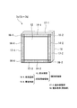
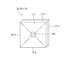
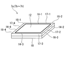
- FIGS. 2A and 2B are schematic external views of the electronic device 7a.
- 1A and 1B show the posture where the casing is raised
- FIGS. 2A and 2B show the posture where the electronic device 7a is sleeping.
- the electronic device 7a has a display screen 12 on the front surface of the housing.
- the electronic device 7 a is provided with a lens 301 of the camera 300 on the bottom (back surface) 18 of the housing.
- the regions located on the outer periphery of the display screen 12 on the front surface of the housing include sides 14-1, 14-2, 14-3, 14-4 (the portions shaded in FIG. 1A) and corners 16 -1, 16-2, 16-3, 16-4 (peripheral areas formed by hatching in FIG. 1A).
- Reference numerals 17-1, 17-2, 17-3, and 17-4 denote housing side surfaces.
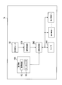
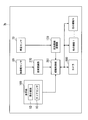
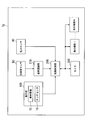
- FIG. 3 is an example of a functional block diagram of the electronic device 7a. The processing flow of the electronic device 7a will be described later.
- the electronic device 7a includes an acceleration sensor 50, a display unit (touch panel) 100, a posture recognition unit (posture determination unit) 270, an activation control unit 280, a camera 300, and other functions 1,.
- Other functions N are provided.
- functions 1, ..., and other functions N are functions (including software and hardware) other than the camera 300. Any other function may be used as long as it can be executed on the electronic device 7a, and examples thereof include image reproduction, music reproduction, telephone call, communication, and execution of game software.
- the acceleration sensor 50 detects acceleration applied to the housing.
- the display unit 100 includes a display screen 12 and a touch sensor 10.
- the display screen 12 displays various information.
- the touch sensor 10 detects a touch on the display screen 12.
- the posture determination unit 270 determines the posture of the housing based on the detection value of the acceleration sensor 50. Specifically, posture determination unit 270 determines whether the posture of the housing is a posture that has occurred as shown in FIGS. 1A and 1B or a posture that has been asleep as shown in FIGS. 2A and 2B.
- the activation control unit 280 controls activation of the camera 300 and other functions.
- the activation control unit 280 controls activation of the camera 300 and other functions based on an explicit instruction (for example, touch of each icon) input from the user via the touch sensor 10.
- the activation control unit 280 automatically activates the camera 300 (without an explicit instruction from the user) when the posture determination unit 270 determines that the posture of the casing has been changed. For example, when the user lays down and uses the housing as shown in FIGS. 2A and 2B and does not activate the camera 300 (for example, when playing an image), the user When the casing is raised as shown in FIGS. 1 and 1B, the activation control unit 280 automatically activates the camera 300 (for example, when the image is being reproduced, the image reproduction is interrupted).
- the electronic device 7b according to the second embodiment (the same applies to the electronic device 7c according to the third embodiment, the electronic device 7d according to the fourth embodiment, and the electronic device 7e according to the fifth embodiment). It is an electronic device that activates the camera 300 based on a condition relating to a gripping state of the housing in addition to the condition of change.
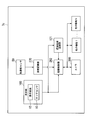
- FIG. 4 is an example of a functional block diagram of the electronic device 7b.
- the appearance of the electronic device 7b is the same as that of the electronic device 7a according to the first embodiment.
- the processing flow of the electronic device 7b will be described later.
- the electronic device 7 b includes an acceleration sensor 50, an illuminance sensor 70, a display unit 100, a gripping mode recognition unit 120, a posture recognition unit 270, a start control unit 281, a camera 300, and other functions 1. ..., other functions N are provided. 4, the same reference numerals as those in FIG. 3 represent the same functions, and thus a part or all of the description is omitted.
- the illuminance sensor 70 detects (measures) illuminance.
- the illuminance sensor 70 can recognize the grip state at a position where the grip state can be recognized (for example, on the same surface (housing rear surface 18 side) as the lens 301 in order to detect the brightness around the lens 301). Install (1 or more).
- the grip state recognition unit 120 recognizes the grip state of the housing by the user. Specifically, the gripping mode recognition unit 120 recognizes (determines) whether or not the gripping mode of the housing by the user is a gripping mode that covers the lens 301 of the camera 300. More specifically, the gripping mode recognition unit 120 recognizes whether or not the gripping mode of the housing by the user is a gripping mode that covers the lens 301 of the camera 300 based on the detection value output from the illuminance sensor 70. .
- the gripping mode recognition unit 120 recognizes whether or not the gripping mode of the housing by the user is a gripping mode that covers the lens 301 as follows.
- the gripping state recognition unit 120 always acquires the detection value output from the illuminance sensor 70 at a constant time interval (for example, every 10 minutes) and temporarily stores it.
- the grip state recognition unit 120 determines the grip state (for example, when the posture determination unit 270 determines that the posture of the housing has occurred)
- the grip state recognition unit 120 for example, 1 hour immediately before the determination.
- a reference value for example, an average value
- the calculated reference value and the detection value output from the illuminance sensor 70 this time (ie, at the time of determination)
- the user recognizes whether or not the gripping mode of the casing by the user is a gripping mode that covers the lens 301. That is, the gripping state recognition unit 120 covers the lens 301 when the detected value this time is smaller than the reference value by a predetermined threshold or more (that is, when it is darker than the predetermined threshold by a certain threshold immediately before the determination).
- the gripping mode recognizing unit 120 does not calculate the reference value when determining the gripping mode, but calculates and temporarily stores the latest reference value as appropriate (for example, at every constant time).
- the latest reference value temporarily stored is compared with the detection value output from the illuminance sensor 70 this time, and the grip mode of the housing by the user determines the lens 301 of the camera 300. You may recognize whether it is the covering aspect which covers.
- the activation control unit 281 controls activation of the camera 300 and other functions.
- the activation control unit 281 controls the activation of the camera 300 and other functions based on an explicit instruction from the user input via the touch sensor 10.
- the activation control unit 281 holds the case where the posture determination unit 270 determines that the posture of the housing has occurred, and the gripping state of the housing by the user is not a gripping mode that covers the lens 301.
- the mode recognition unit 120 recognizes (that is, when the gripping mode recognition unit 120 recognizes that the gripping mode of the housing by the user is a gripping mode that does not cover the lens 301)
- the camera 300 is automatically activated. For example, when the user lays down and uses the housing as shown in FIGS.
- the activation control unit 281 (for example, image reproduction when the image is reproduced) The camera 300 is automatically activated.
- the electronic device 7c according to the third embodiment is different from the electronic device 7b according to the second embodiment in that it recognizes the manner in which the user grips the housing based on the detection value output from the touch sensor 10.
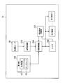
- FIG. 5 is an example of a functional block diagram of the electronic device 7c.
- the appearance of the electronic device 7c is the same as that of the electronic device 7a according to the first embodiment.
- the processing flow of the electronic device 7c will be described later.
- the electronic device 7c includes an acceleration sensor 50, a display unit 100, a grip state recognition unit 121, a posture recognition unit 270, an activation control unit 282, a camera 300, and other functions 1,.
- Function N is provided.
- the same reference numerals as those in FIG. 3 or 4 represent the same functions, and thus a part or all of the description is omitted.
- the grip state recognition unit 121 recognizes the grip state of the housing by the user. Specifically, the gripping mode recognition unit 121 recognizes (determines) whether or not the gripping mode of the housing by the user is a gripping mode that covers the lens 301 of the camera 300. More specifically, the grip mode recognition unit 121 determines whether the grip mode of the housing by the user covers the lens 301 of the camera 300 based on the detection value (touch position) output from the touch sensor 10. Recognize.
- the gripping mode recognition unit 121 recognizes whether or not the gripping mode of the housing by the user is a gripping mode that covers the lens 301 as follows.
- a detection value pattern of the touch sensor 10 in a typical gripping mode that covers the lens 301 and a detection value pattern of the touch sensor 10 in a typical gripping mode that does not cover the lens 301 are collected and stored in advance.
- the grip state recognition unit 121 determines the grip mode (for example, when the posture determination unit 270 determines that the posture of the housing has occurred), the grip state recognition unit 121 and the touch sensor 10 is compared with the detection value output this time, and it is recognized whether or not the gripping mode of the casing by the user is a gripping mode that covers the lens 301. That is, the gripping state recognition unit 121 detects the touch sensor 10 in a typical gripping mode that covers the lens 301 rather than the detection value pattern of the touch sensor 10 in the typical gripping mode in which the current detection value does not cover the lens 301. When the pattern is close to the detected value pattern, it is recognized that the gripping mode of the housing by the user is a gripping mode that covers the lens 301, and in the opposite case, the gripping mode is not determined to cover the lens 301.
- the activation control unit 282 controls activation of the camera 300 and other functions.
- the activation control unit 282 controls activation of the camera 300 and other functions based on an explicit instruction from the user input via the touch sensor 10.
- the activation control unit 282 holds the case when the posture determination unit 270 determines that the posture of the housing has occurred and the gripping mode of the housing by the user is not a gripping mode that covers the lens 301.
- the mode recognition unit 121 recognizes, the camera 300 is automatically activated.
- the user lays down and uses the housing as shown in FIGS. 2A and 2B and does not activate the camera 300 (for example, when playing an image)
- the user 1B when it is determined that the case 301 is raised and the lens 301 is not covered by the user's finger or the like
- the activation control unit 282 for example, image reproduction when the image is reproduced
- the camera 300 is automatically activated.
- the electronic device 7d recognizes the manner in which the user grips the housing based on the detection value output from the touch sensor 20 provided on the housing side surface portion 17. Different from the electronic device 7b.
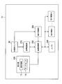
- FIG. 6 is an example of a functional block diagram of the electronic device 7d.
- the appearance of the electronic device 7d is the same as that of the electronic device 7a according to the first embodiment.
- the processing flow of the electronic device 7d will be described later.
- the electronic device 7 d includes a touch sensor (side sensor) 20, an acceleration sensor 50, a display unit 100, a gripping state recognition unit 122, a posture recognition unit 270, an activation control unit 283, a camera 300, and others.
- a touch sensor side sensor
- an acceleration sensor 50 a sensor for detecting the acceleration of the electronic device 7 d
- a display unit 100 includes a gripping state recognition unit 122, a posture recognition unit 270, an activation control unit 283, a camera 300, and others.
- the touch sensor 20 is disposed on the case side surface portions 17-1, 17-2, 17-3, 17-4, and touches the case side surface portions 17-1, 17-2, 17-3, 17-4. To detect.
- the grip state recognition unit 122 recognizes the grip state of the casing by the user. Specifically, the gripping mode recognition unit 122 recognizes (determines) whether or not the gripping mode of the housing by the user is a gripping mode that covers the lens 301 of the camera 300. More specifically, the grip state recognition unit 122 determines whether the grip state of the housing by the user covers the lens 301 of the camera 300 based on the detection value (touch position) output from the touch sensor 20. Recognize.
- the gripping mode recognition unit 122 recognizes whether or not the gripping mode of the housing by the user is a gripping mode that covers the lens 301 as follows.
- the detection value pattern of the touch sensor 20 in a typical gripping mode that covers the lens 301 and the detection value pattern of the touch sensor 20 in a typical gripping mode that does not cover the lens 301 are preliminarily set. Collect and remember each one.
- the grip state recognition unit 122 determines the grip state (for example, when the posture determination unit 270 determines that the posture of the housing has occurred), the grip state recognition unit 122 and the touch sensor 20 is compared with the detection value output this time, and it is recognized whether or not the gripping mode of the housing by the user is a gripping mode that covers the lens 301.
- the activation control unit 283 controls activation of the camera 300 and other functions.
- the activation control unit 283 controls activation of the camera 300 and other functions based on an explicit instruction input from the user via the touch sensor 10.
- the activation control unit 283 is a case where the posture determination unit 270 determines that the posture of the housing has occurred, and the gripping mode of the housing by the user is not a gripping mode that covers the lens 301 of the camera.
- the gripping state recognition unit 122 recognizes, the camera 300 is automatically activated.
- the user lays down and uses the housing as shown in FIGS. 2A and 2B and does not activate the camera 300 (for example, when playing an image)
- the user 1B when it is determined that the case 301 is raised and the lens 301 is not covered by the user's finger or the like
- the activation control unit 283 for example, image reproduction when reproducing an image
- the camera 300 is automatically activated.
- the electronic device 7e according to the fifth embodiment is that the electronic device 7e according to the second embodiment recognizes the electronic device 7e according to the second embodiment based on a captured image (through image) obtained by the camera 300 that temporarily activates the gripping state of the housing by the user. Different from 7b.
- FIG. 7 is an example of a functional block diagram of the electronic device 7e.
- the appearance of the electronic device 7e is the same as that of the electronic device 7a according to the first embodiment.
- the processing flow of the electronic device 7e will be described later.
- the electronic device 7e includes an acceleration sensor 50, a display unit 100, a grip state recognition unit 123, a posture recognition unit 270, an activation control unit 284, a camera 300, and other functions 1,.
- Function N is provided.
- the same reference numerals as those in FIGS. 3 to 6 represent the same functions, and thus a part or all of the description is omitted.
- the activation control unit 284 controls activation of the camera 300 and other functions.
- the activation control unit 284 controls the activation of the camera 300 and other functions based on an explicit instruction from the user input via the touch sensor 10.
- the activation control unit 284 is a case where the posture determination unit 270 determines that the posture of the housing has occurred, and the gripping mode of the housing by the user is not a gripping mode that covers the lens 301 of the camera.
- the grip state recognition unit 123 recognizes, the camera 300 is automatically activated.
- the activation control unit 284 temporarily activates the camera 300 when the posture determination unit 270 determines that the posture of the housing has been raised. In other words, the activation control unit 284 temporarily activates the camera 300 in order to cause the gripping mode recognition unit 123 to recognize the gripping mode when the posture determination unit 270 determines that the casing is in the posture in which it has occurred. Subsequently, the activation control unit 284 activates (executes) the temporarily activated camera 300 when the gripping mode recognition unit 123 recognizes that the gripping mode of the housing by the user is not a gripping mode that covers the lens 301. Maintain (continue). That is, the camera 300 is kept activated until there is an explicit instruction to terminate activation.
- the activation control unit 284 terminates the activation of the temporarily activated camera 300 when the gripping mode recognition unit 123 recognizes that the gripping mode of the housing by the user is a gripping mode that covers the lens 301.
- the activation control unit 284 may activate a function that was activated before the camera 300 is temporarily activated (may be restored to the function that was activated before being temporarily activated).
- the grip state recognition unit 123 recognizes the grip state of the casing by the user. Specifically, the gripping mode recognition unit 123 recognizes (determines) whether or not the gripping mode of the housing by the user is a gripping mode that covers the lens 301 of the camera 300. More specifically, the grip mode recognition unit 123 is a grip mode in which the grip mode of the housing by the user covers the lens 301 of the camera 300 based on the image (through image) captured by the camera 300 that is temporarily activated. Recognize whether there is.
- the gripping mode recognition unit 123 recognizes that the gripping mode covers the lens 301, and the luminance value of the captured image is If it is equal to or greater than the threshold value, it is recognized that the grip state does not cover the lens 301.
- the gripping mode recognition unit 123 is a gripping mode that covers the lens 301 when the user's palm, finger, or the like is actually captured (or estimated to be captured) in the captured image. If the user's palm, finger, or the like is not actually captured (or is estimated not to be captured), it is recognized that the user does not grasp the lens 301.
- the electronic device 7f according to the sixth embodiment is an electronic device that automatically activates the camera 300 based on the condition of whether or not the casing is shaken in addition to the above-described condition of changing the attitude of the casing.
- FIG. 8 is an example of a functional block diagram of the electronic device 7f.
- the appearance of the electronic device 7f is the same as that of the electronic device 7a according to the first embodiment.
- the processing flow of the electronic device 7f will be described later.
- the electronic device 7f includes an acceleration sensor 50, a display unit 100, a motion recognition unit 260, a posture recognition unit 270, an activation control unit 285, a camera 300, and other functions 1,. N is provided.
- the same reference numerals as those in FIGS. 3 to 7 represent the same functions, and thus a part or all of the description is omitted.
- the motion recognition unit 260 recognizes the movement of the housing based on the detection value of the acceleration sensor 50. For example, when the user shakes the housing, the motion recognition unit 260 detects the acceleration in the shake direction.
- the activation control unit 285 controls activation of the camera 300 and other functions.
- the activation control unit 285 controls the activation of the camera 300 and other functions based on an explicit instruction from the user input via the touch sensor 10.
- the activation control unit 285 is a camera that is used when the posture determination unit 270 determines that the posture of the housing has occurred and the motion recognition unit 260 recognizes that the housing has been shaken. 300 is automatically activated. For example, when the user lays down and uses the housing as shown in FIGS. 2A and 2B and does not activate the camera 300 (for example, when playing an image), the user And when the case is shaken after raising the case as shown in 1B (or when the user raises the case as shown in FIGS. 1A and 1B after shaking the case), The activation control unit 285 automatically activates the camera 300 (for example, when the image is being reproduced, the image reproduction is interrupted).
- the electronic device 7g according to the seventh embodiment is an electronic device that automatically activates the camera 300 based on the condition of whether or not the casing is pressed in addition to the above-described condition of the attitude change of the casing.
- FIG. 9 is an example of a functional block diagram of the electronic device 7g.
- the appearance of the electronic device 7g is the same as that of the electronic device 7a according to the first embodiment.
- the processing flow of the electronic device 7g will be described later.
- the electronic device 7g includes a pressure sensor 40, an acceleration sensor 50, a display unit 100, a posture recognition unit 270, an activation control unit 286, a camera 300, and other functions 1,. Is provided. 9, the same reference numerals as those in FIGS. 3 to 8 represent the same functions, and thus a part or all of the description is omitted.
- the pressure sensor 40 detects the pressure applied to a predetermined position of the housing.
- the pressure sensor 40 is disposed in the front peripheral area (the front side section 14 and the front corner section 16), and detects pressure applied to the front peripheral area.
- the activation control unit 286 controls activation of the camera 300 and other functions.
- the activation control unit 286 controls activation of the camera 300 and other functions based on an explicit instruction input from the user via the touch sensor 10.
- the activation control unit 286 is a case where the posture determination unit 270 determines that the posture of the housing has occurred, and a predetermined position (for example, the front side portions 14-1, 14-) of the housing. 2, 14-3, or 14-4), when the pressure sensor 40 detects pressurization, the camera 300 is automatically activated.
- the user 1B when the front side part 14 is pressed after the casing is raised as shown in FIGS. 1A and 1B (or after the user presses the front side part, the case as shown in FIGS. 1A and 1B)
- the activation control unit 286 automatically activates the camera 300 (for example, when the image is being reproduced, the image reproduction is interrupted).
- the electronic device 7h according to the eighth embodiment is an electronic device that automatically activates the camera 300 based on a condition whether or not a predetermined function is activated in addition to the above-described condition that the posture of the casing is changed. is there.
- FIG. 10 is an example of a functional block diagram of the electronic device 7h.
- the appearance of the electronic device 7h is the same as that of the electronic device 7a according to the first embodiment.
- the processing flow of the electronic device 7h will be described later.
- the electronic device 7h includes an acceleration sensor 50, a display unit 100, a posture recognition unit 270, an activation control unit 287, a camera 300, and other functions 1,.
- the same reference numerals as those in FIGS. 3 to 9 represent the same functions, and thus a part or all of the description is omitted.
- the activation control unit 287 controls activation of the camera 300 and other functions.
- the activation control unit 287 controls activation of the camera 300 and other functions based on an explicit instruction from the user input via the touch sensor 10.
- the activation control unit 287 automatically activates the camera 300 when the posture determination unit 270 determines that the case has become a posture and the predetermined function is activated. Start. For example, when the user wakes up the housing as shown in FIGS. 1A and 1B when the user lays down the housing as shown in FIGS. 2A and 2B and the camera 300 is not activated.
- a predetermined function for example, image playback
- the predetermined function is interrupted and the camera 300 is automatically activated.
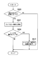
- 11A, 11B, and 11C are examples of a flowchart showing a flow of processing of the electronic apparatus (7a and the like) according to the present invention.
- 12A and 12B are examples of a flowchart showing the flow of processing of the electronic apparatus (7f etc.) according to the present invention.
- Each flowchart starts every time the acceleration sensor 50 detects an acceleration applied to the housing. At the start of each flowchart, it is assumed that the housing is in a sleeping state and the camera 300 is not activated.
- the posture determination unit 270 of the electronic device 7a determines whether or not the housing is in the posture in which it is raised based on the detection result of the acceleration sensor 50 (step S600). If the housing is not in the raised position (step S600: No), the flowchart of FIG. 11A ends. On the other hand, when the housing is in the raised position (step S600: Yes), the activation control unit 280 activates the camera 300 (step S610). Then, the flowchart of FIG. 11A ends.
- step S600 the posture determination unit 270 of the electronic device 7b determines whether or not the housing is in a posture in which the housing has been raised based on the detection result of the acceleration sensor 50 (step S600).
- step S600 when the housing is not in the raised position (step S600: No), the flowchart of FIG. 11B ends.
- step S ⁇ b> 600 when the casing is in the raised posture (step S ⁇ b> 600: Yes), the grip state recognition unit 120 determines that the grip state of the housing by the user is a lens based on the detection value output from the illuminance sensor 70. It is determined whether or not the grip state covers 301 (step S604).
- step S604 when the grip mode of the housing by the user is a grip mode that covers the lens 301 (step S604: Yes), the flowchart of FIG. 11B ends.
- step S604: No when the gripping mode of the housing by the user is not a gripping mode that covers the lens 301 in step S604 (step S604: No), the activation control unit 281 activates the camera 300 (step S610). Then, the flowchart of FIG. 11B ends.
- FIG. 11B which is the same as that of the electronic device 7b.
- the posture determination unit 270 of the electronic device 7c determines whether or not the housing is in a posture in which the housing has been raised based on the detection result of the acceleration sensor 50 (step S600).
- step S600 when the housing is not in the raised position (step S600: No), the flowchart of FIG. 11B ends.
- step S ⁇ b> 600 when the housing is in the raised posture (step S ⁇ b> 600: Yes), the grip state recognition unit 121 determines that the grip state of the housing by the user is a lens based on the detection value output from the touch sensor 10. It is determined whether or not the grip state covers 301 (step S604).
- step S604 when the grip mode of the housing by the user is a grip mode that covers the lens 301 (step S604: Yes), the flowchart of FIG. 11B ends.
- step S604 if the gripping mode of the housing by the user is not a gripping mode that covers the lens 301 (step S604: No), the activation control unit 282 activates the camera 300 (step S610). Then, the flowchart of FIG. 11B ends.
- FIG. 11B which is the same as that of the electronic device 7b.
- the posture determination unit 270 of the electronic device 7d determines whether or not the housing is in the posture in which it has been raised based on the detection result of the acceleration sensor 50 (step S600).
- step S600 when the housing is not in the raised position (step S600: No), the flowchart of FIG. 11B ends.
- step S ⁇ b> 600 when the casing is in the raised posture (step S ⁇ b> 600: Yes), the grip state recognition unit 122 determines that the grip state of the casing by the user is a lens based on the detection value output from the touch sensor 20. It is determined whether or not the grip state covers 301 (step S604).
- step S604 when the grip mode of the housing by the user is a grip mode that covers the lens 301 (step S604: Yes), the flowchart of FIG. 11B ends.
- step S604 if the gripping mode of the housing by the user is not a gripping mode that covers the lens 301 (step S604: No), the activation control unit 283 activates the camera 300 (step S610). Then, the flowchart of FIG. 11B ends.
- step S600 the posture determination unit 270 of the electronic device 7e determines whether or not the housing is in the posture in which it is raised based on the detection result of the acceleration sensor 50 (step S600).
- step S600 when the casing is not in the raised position (step S600: No), the flowchart of FIG. 11C ends.
- step S600 when the chassis is in the raised position (step S600: Yes), the activation control unit 284 temporarily activates the camera 300 (step S602). Subsequent to step S ⁇ b> 602, the grip state recognition unit 123 grips the case in which the user grips the casing covers the lens 301 of the camera 300 based on the image (through image) captured by the camera 300 that is temporarily activated in step S ⁇ b> 602. It is determined whether or not it is an aspect (step S604).
- step S604 when the gripping mode of the housing by the user is a gripping mode that covers the lens 301 (step S604: Yes), the activation control unit 284 ends the activation (execution) of the camera 300 that is temporarily activated in step S602. (Step S612). Then, the flowchart of FIG. 11C ends.
- step S604 when the gripping state of the housing by the user is not a gripping state that covers the lens 301 (step S604: No), the flowchart of FIG. 11C ends.
- the activation control unit 284 maintains (continues) the activation of the camera 300 that has been temporarily activated in step S602 when the user does not grasp the housing 301 so that the case 301 is grasped.
- the camera 300 is kept activated until there is a proper instruction).
- step S600 the posture determination unit 270 of the electronic device 7f determines whether or not the housing is in a posture in which the housing has been raised based on the detection result of the acceleration sensor 50 (step S600).
- step S600 when the casing is not in the raised position (step S600: No), the flowchart of FIG. 12A ends.
- step S600 when the housing is in the raised position (step S600: Yes), it is determined whether or not a predetermined operation has been performed on the housing (step S606). Specifically, the motion recognition unit 260 determines whether or not the housing is shaken based on the detection value output from the acceleration sensor 50 (step S606).
- step S606 If the casing is not shaken in step S606 (step S606: No), the flowchart of FIG. 12A ends. On the other hand, when the housing is shaken in step S606 (step S606: Yes), the activation control unit 285 activates the camera 300 (step S610). Then, the flowchart of FIG. 12A ends.
- FIG. 12A which is the same as that of the electronic device 7f.
- the posture determination unit 270 of the electronic device 7g determines whether or not the housing is in the posture in which it has been raised based on the detection result of the acceleration sensor 50 (step S600).
- step S600 when the casing is not in the raised position (step S600: No), the flowchart of FIG. 12A ends.
- step S600 when the housing is in the raised position (step S600: Yes), it is determined whether or not a predetermined operation has been performed on the housing (step S606). Specifically, the activation control unit 286 determines whether or not the casing has been pressed based on the detection value output from the pressure sensor 40 (step S606).
- step S606 when the housing is not pressed (step S606: No), the flowchart of FIG. 12A ends.
- step S606: Yes when the casing is pressed in step S606 (step S606: Yes), the activation control unit 286 activates the camera 300 (step S610). Then, the flowchart of FIG. 12A ends.
- step S600 when the housing is not in the raised position (step S600: No), the flowchart of FIG. 12B ends.
- step S600 when the chassis is in the raised position (step S600: Yes), the activation control unit 287 determines whether or not a predetermined function (for example, image reproduction) is activated (executed) (Ste S608).
- a predetermined function for example, image reproduction
- step S608 when the predetermined function is not activated (step S608: No), the flowchart of FIG. 12B ends. That is, when a function other than a predetermined function is activated, the camera 300 is not activated even if the casing is raised.
- step S608: Yes when the predetermined function is activated in step S608 (step S608: Yes), the activation control unit 287 activates the camera 300 (step S610). Then, the flowchart of FIG. 12B ends.
- the operability can be further improved. That is, the camera 300 can be activated by a simple operation of raising the housing. Further, according to each of the electronic devices 7b to 7h, when the camera 300 is awakened, the camera 300 can be activated appropriately according to a predetermined condition.
- a method of recognizing the grip mode based on the brightness around the lens 301 (the electronic device 7b according to the second embodiment), and the grip mode based on the touch position on the display screen 12 are recognized.
- the method for recognizing the aspect has been illustrated, the method for recognizing the grip aspect is not limited to the above.
- the grip mode may be recognized based on the detection value of the pressure sensor 40.
- the grip state recognition unit grips the case where the grip state of the housing covers the lens 301 by the user. You may recognize whether it is an aspect.
- the predetermined operation is not limited to the above.
- an operation of touching an arbitrary place (not a predetermined icon) on the display screen 12 may be performed.
- a program for executing the processing of the electronic devices 7a to 7h according to the embodiment of the present invention is recorded on a computer-readable recording medium, and the program recorded on the recording medium is read into a computer system and executed. Accordingly, the above-described various processes related to the electronic devices 7a to 7h according to the embodiment of the present invention may be performed.
- the “computer system” may include an OS and hardware such as peripheral devices. Further, the “computer system” includes a homepage providing environment (or display environment) if a WWW system is used.
- Computer-readable recording medium means a floppy (registered trademark) disk, a magneto-optical disk, an SD card, a writable non-volatile memory such as a flash memory, a portable medium such as a CD-ROM, and a computer system.
- a built-in storage device such as a hard disk.
- the “computer-readable recording medium” means a volatile memory (for example, DRAM (Dynamic DRAM) in a computer system that becomes a server or a client when a program is transmitted through a network such as the Internet or a communication line such as a telephone line. Random Access Memory)), etc., which hold programs for a certain period of time.
- the program may be transmitted from a computer system storing the program in a storage device or the like to another computer system via a transmission medium or by a transmission wave in the transmission medium.
- the “transmission medium” for transmitting the program refers to a medium having a function of transmitting information, such as a network (communication network) such as the Internet or a communication line (communication line) such as a telephone line.
- the program may be for realizing a part of the functions described above. Furthermore, what can implement
- an electronic device includes a camera, an acceleration sensor that detects acceleration applied to the housing, a posture determination unit that determines a posture of the housing based on a detection value of the acceleration sensor, and a housing
- An activation control unit that activates the camera when the posture determination unit determines that the posture has occurred, and a gripping mode recognition unit that recognizes a gripping mode of the housing by the user
- the startup control unit Is a case where the posture determination unit determines that the posture of the housing has occurred
- the grip state recognition unit determines that the grip state of the housing by the user is not a grip state covering the lens of the camera. If recognized, activate the camera.
- an illuminance sensor is further provided, and the grip mode recognition unit determines whether or not the grip mode of the casing by the user covers the lens of the camera based on the detection value output from the illuminance sensor. It is possible to adopt a configuration that recognizes this.
- the said grip aspect recognition part is a grip aspect in which the grip aspect of the housing
- a touch sensor for recognizing a touch on the side surface of the housing is further provided, and the grip mode recognition unit is configured so that the grip mode of the housing by the user is a camera based on the position of the touch on the side surface. It is possible to adopt a configuration for recognizing whether or not the gripping mode covers the other lens.
- the activation control unit activates the camera temporarily when the posture determination unit determines that the posture of the housing has occurred, and the grip state recognition unit Based on the image captured by the temporarily activated camera, it is possible to recognize whether or not the gripping mode of the casing by the user is a gripping mode that covers the lens of the camera.
Landscapes
- Physics & Mathematics (AREA)
- General Physics & Mathematics (AREA)
- Engineering & Computer Science (AREA)
- General Engineering & Computer Science (AREA)
- Theoretical Computer Science (AREA)
- Human Computer Interaction (AREA)
- Studio Devices (AREA)
- Details Of Cameras Including Film Mechanisms (AREA)
- Camera Bodies And Camera Details Or Accessories (AREA)
- Position Input By Displaying (AREA)
Abstract
電子機器(7a)は、カメラ(300)と、筐体に加わる加速度を検出する加速度センサ(50)と、加速度センサ(50)の検出値に基づいて筐体の姿勢を判定する姿勢判定部(270)と、筐体の姿勢が起きた姿勢になったと姿勢判定部(270)が判定した場合に、カメラ(300)を起動させる起動制御部(280)とを備える。
Description
本発明は、電子機器に関する。
本願は、2011年8月10日に出願された日本国特願2011-175091号、及び、2012年1月18日に出願された日本国特願2012-008271号に基づき優先権を主張し、その内容をここに援用する。
本願は、2011年8月10日に出願された日本国特願2011-175091号、及び、2012年1月18日に出願された日本国特願2012-008271号に基づき優先権を主張し、その内容をここに援用する。
従来、種々のセンサを備える電子機器が知られている(例えば、特許文献1参照)。
しかしながら、従来の電子機器の場合、ユーザの操作性に改善の余地がある。本発明に係る態様は、操作性を一層向上させた電子機器を提供することを目的とする。
本発明の一態様に係る電子機器は、筐体と、カメラと、前記筐体に加わる加速度を検出する加速度センサと、前記加速度センサの検出値に基づいて筐体の姿勢を判定する姿勢判定部と、前記筐体の姿勢が起きた姿勢になったと前記姿勢判定部が判定した場合に、前記カメラを起動させる起動制御部と、ユーザによる筐体の把持態様を認識する把持態様認識部とを備え、前記起動制御部は、前記筐体の姿勢が前記起きた姿勢になったと前記姿勢判定部が判定した場合であって、かつ、前記ユーザによる前記筐体の把持態様が前記カメラのレンズを覆う把持態様でないと前記把持態様認識部が認識した場合に、前記カメラを起動させる。
また、上記電子機器の他の態様において、筐体と、カメラと、前記筐体に加わる加速度を検出する加速度センサと、前記加速度センサの検出値に基づいて筐体の姿勢を判定する姿勢判定部と、前記筐体の姿勢が起きた姿勢になったと前記姿勢判定部が判定した場合に、前記カメラを起動させる起動制御部と、前記加速度センサの検出値に基づいて前記筐体の動きを認識する動き認識部とを備え、前記起動制御部は、前記筐体の姿勢が前記起きた姿勢になったと前記姿勢判定部が判定した場合であって、かつ、前記筐体が振られたと前記動き認識部が認識した場合に、前記カメラを起動させる。
また、上記電子機器の他の態様において、筐体と、カメラと、前記筐体に加わる加速度を検出する加速度センサと、前記加速度センサの検出値に基づいて筐体の姿勢を判定する姿勢判定部と、前記筐体の姿勢が起きた姿勢になったと前記姿勢判定部が判定した場合に、前記カメラを起動させる起動制御部と、前記筐体の所定位置に加えられた圧力を検出する圧力センサとを備え、前記起動制御部は、前記筐体の姿勢が前記起きた姿勢になったと前記姿勢判定部が判定した場合であって、かつ、前記筐体の所定位置への加圧を前記圧力センサが検出した場合に、前記カメラを起動させる。
また、上記電子機器の他の態様において、筐体と、カメラと、前記筐体に加わる加速度を検出する加速度センサと、前記加速度センサの検出値に基づいて筐体の姿勢を判定する姿勢判定部と、前記筐体の姿勢が起きた姿勢になったと前記姿勢判定部が判定した場合に、前記カメラを起動させる起動制御部と、前記カメラの機能以外の他の複数の機能とを備え、前記起動制御部は、前記カメラの起動に加え、前記他の複数の機能の夫々の起動を制御し、前記筐体の姿勢が前記起きた姿勢になったと前記姿勢判定部が判定した場合であって、かつ、所定の機能を起動させている場合に、前記カメラを起動させる。
本発明に係る態様によれば、操作性を一層向上させることができる。
(第1の実施形態)
以下、図面を参照しながら本発明の第1の実施形態について説明する。第1の実施形態による電子機器7aは、筐体(即ち、電子機器7a)の姿勢変化(寝た状態から起きた状態に変化)という条件のみで、カメラ300を自動的に起動させる電子機器である。
以下、図面を参照しながら本発明の第1の実施形態について説明する。第1の実施形態による電子機器7aは、筐体(即ち、電子機器7a)の姿勢変化(寝た状態から起きた状態に変化)という条件のみで、カメラ300を自動的に起動させる電子機器である。
図1Aおよび1B、図2Aおよび2Bは、電子機器7aの外観模式図である。なお、図1Aおよび1Bは筐体が起きた姿勢、図2Aおよび2Bは電子機器7aが寝た姿勢を表している。電子機器7aは、図1A及び図2Aに示すように、筐体前面部に、表示画面12を有する。また、電子機器7aは、図1B及び図2Bに示すように、筐体底部(背面部)18に、カメラ300のレンズ301が設けられている。
筐体前面部上の表示画面12の外周に位置する領域は、辺部14-1、14-2、14-3、14-4(図1Aにて網掛表示した部分)、及び、角部16-1、16-2、16-3、16-4(図1Aにて斜線表示した部分)から構成される周縁領域である。符号17-1、17-2、17-3、17-4は、筐体側面部である。
図3は、電子機器7aの機能ブロック図の一例である。なお、電子機器7aの処理の流れについては後述する。
電子機器7aは、図3に示すように、加速度センサ50、表示部(タッチパネル)100、姿勢認識部(姿勢判定部)270、起動制御部280、カメラ300、及び、他の機能1、…、他の機能Nを備える。
他の機能1、…、他の機能Nとは、カメラ300以外の機能(ソフトウェア及びハードウェアを含む)である。他の機能は、電子機器7a上で実行され得るものであればよく、例えば、画像再生、楽曲再生、通話、通信、ゲームソフトの実行などが該当する。
加速度センサ50は、筐体に加わる加速度を検出する。表示部100は、表示画面12とタッチセンサ10から構成される。表示画面12は、種々の情報を表示する。タッチセンサ10は、表示画面12へのタッチを検出する。
姿勢判定部270は、加速度センサ50の検出値に基づいて筐体の姿勢を判定する。具体的には、姿勢判定部270は、筐体の姿勢が図1Aおよび1Bに示すように起きた姿勢であるか、図2Aおよび2Bに示すように寝た姿勢であるかを判定する。
起動制御部280は、カメラ300、及び、他の機能の起動を制御する。例えば、起動制御部280は、タッチセンサ10を介して入力されたユーザからの明示的な指示(例えば、各アイコンのタッチ)に基づいて、カメラ300、及び、他の機能の起動を制御する。
また、起動制御部280は、筐体の姿勢が起きた姿勢になったと姿勢判定部270が判定した場合に、カメラ300を自動的に(ユーザからの明示的な指示無しに)起動させる。例えば、ユーザが、図2Aおよび2Bに示すように筐体を寝かせて使用し、かつ、カメラ300を起動させていないときに(例えば、画像を再生させているときに)、ユーザが、図1Aおよび1Bに示すように筐体を起こした場合、起動制御部280は、(例えば、画像を再生させている場合は画像再生を中断し)カメラ300を自動的に起動させる。
(第2の実施形態)
続いて、本発明の第2の実施形態について説明する。第2の実施形態による電子機器7b(第3の実施形態による電子機器7c、第4の実施形態による電子機器7d、第5の実施形態による電子機器7eも同様)は、上述の筐体の姿勢変化という条件に加え、筐体の把持態様に関する条件に基づいて、カメラ300を起動させる電子機器である。
続いて、本発明の第2の実施形態について説明する。第2の実施形態による電子機器7b(第3の実施形態による電子機器7c、第4の実施形態による電子機器7d、第5の実施形態による電子機器7eも同様)は、上述の筐体の姿勢変化という条件に加え、筐体の把持態様に関する条件に基づいて、カメラ300を起動させる電子機器である。
図4は、電子機器7bの機能ブロック図の一例である。なお、電子機器7bの外観は、第1の実施形態による電子機器7aと同様である。また、電子機器7bの処理の流れについては後述する。
電子機器7bは、図4に示すように、加速度センサ50、照度センサ70、表示部100、把持態様認識部120、姿勢認識部270、起動制御部281、カメラ300、及び、他の機能1、…、他の機能Nを備える。なお、図4において、図3と同一の符号は、同一の機能を表しているため、説明の一部又は全部を省略する。
照度センサ70は、照度を検出(測定)する。なお、照度センサ70は、把持態様が認識できる位置(例えば、レンズ301の周辺の明るさを検出するためレンズ301と同一の面(筐体背面部18)側)に、把持態様が認識できる個数(1以上)、設置する。
把持態様認識部120は、ユーザによる筐体の把持態様を認識する。具体的には、把持態様認識部120は、ユーザによる筐体の把持態様がカメラ300のレンズ301を覆う把持態様であるか否かを認識(判定)する。より詳細には、把持態様認識部120は、照度センサ70から出力された検出値に基づいて、ユーザによる筐体の把持態様がカメラ300のレンズ301を覆う把持態様であるか否かを認識する。
例えば、把持態様認識部120は、以下のように、ユーザによる筐体の把持態様がレンズ301を覆う把持態様であるか否かを認識する。
把持態様認識部120は、常時一定時間毎(例えば、10分毎)に、照度センサ70から出力された検出値を取得し、一時記憶しておく。把持態様認識部120は、把持態様の判断を行うときに(例えば、筐体の姿勢が起きた姿勢になったと姿勢判定部270が判定したときに)、判断直前の一定期間(例えば、1時間)に照度センサ70から出力された検出値に基づいて基準値(例えば、平均値)を算出し、算出した基準値と、今回(即ち、判断時)、照度センサ70から出力された検出値とを比較し、ユーザによる筐体の把持態様がレンズ301を覆う把持態様であるか否かを認識する。
即ち、把持態様認識部120は、今回の検出値が基準値に対し所定の閾値以上小さい場合(即ち、判断直前の一定期間の明るさよりも所定の閾値以上暗い場合)には、レンズ301を覆う把持態様であると認識し、今回の検出値が基準値に対し所定の閾値以上小さくない場合(即ち、直前の一定期間の明るさよりも所定の閾値以上暗くない場合)には、レンズ301を覆う把持態様でないと認識する。
なお、把持態様認識部120は、把持態様の判断を行うときに基準値を算出するのではなく、適宜(例えば、上記常時一定時間毎)、最新の基準値を算出し一時記憶しておき、把持態様の判断を行うときに、一時記憶している最新の基準値と、今回、照度センサ70から出力された検出値とを比較し、ユーザによる筐体の把持態様がカメラ300のレンズ301を覆う把持態様であるか否かを認識してもよい。
起動制御部281は、カメラ300、及び、他の機能の起動を制御する。例えば、起動制御部281は、タッチセンサ10を介して入力されたユーザからの明示的な指示に基づいて、カメラ300、及び、他の機能の起動を制御する。
また、起動制御部281は、筐体の姿勢が起きた姿勢になったと姿勢判定部270が判定した場合であって、かつ、ユーザによる筐体の把持態様がレンズ301を覆う把持態様でないと把持態様認識部120が認識した場合(即ち、ユーザによる筐体の把持態様がレンズ301を覆わない把持態様であると把持態様認識部120が認識した場合)、カメラ300を自動的に起動させる。例えば、ユーザが、図2Aおよび2Bに示すように筐体を寝かせて使用し、かつ、カメラ300を起動させていないときに(例えば、画像を再生させているときに)、ユーザが、図1Aおよび1Bに示すように筐体を起こし、かつ、ユーザの指などによってレンズ301が覆われていないと判断された場合、起動制御部281は、(例えば、画像を再生させている場合は画像再生を中断し)カメラ300を自動的に起動させる。
(第3の実施形態)
続いて、本発明の第3の実施形態について説明する。第3の実施形態による電子機器7cは、ユーザによる筐体の把持態様をタッチセンサ10から出力された検出値に基づいて認識する点が、第2の実施形態による電子機器7bと異なる。
続いて、本発明の第3の実施形態について説明する。第3の実施形態による電子機器7cは、ユーザによる筐体の把持態様をタッチセンサ10から出力された検出値に基づいて認識する点が、第2の実施形態による電子機器7bと異なる。
図5は、電子機器7cの機能ブロック図の一例である。なお、電子機器7cの外観は、第1の実施形態による電子機器7aと同様である。また、電子機器7cの処理の流れについては後述する。
電子機器7cは、図5に示すように、加速度センサ50、表示部100、把持態様認識部121、姿勢認識部270、起動制御部282、カメラ300、及び、他の機能1、…、他の機能Nを備える。なお、図5において、図3又は図4と同一の符号は、同一の機能を表しているため、説明の一部又は全部を省略する。
把持態様認識部121は、ユーザによる筐体の把持態様を認識する。具体的には、把持態様認識部121は、ユーザによる筐体の把持態様がカメラ300のレンズ301を覆う把持態様であるか否かを認識(判定)する。より詳細には、把持態様認識部121は、タッチセンサ10から出力された検出値(タッチ位置)に基づいて、ユーザによる筐体の把持態様がカメラ300のレンズ301を覆う把持態様であるか否かを認識する。
通常、筐体前面部の表示画面12に指等が触れる位置又は触れる量は、レンズ301を覆うような把持態様の場合と、レンズ301を覆わないような把持態様の場合とで異なる。従って、例えば、把持態様認識部121は、以下のように、ユーザによる筐体の把持態様がレンズ301を覆う把持態様であるか否かを認識する。
予め、レンズ301を覆う代表的な把持態様におけるタッチセンサ10の検出値のパターンと、レンズ301を覆わない代表的な把持態様におけるタッチセンサ10の検出値のパターンを採取し夫々記憶しておく。把持態様認識部121は、把持態様の判断を行うときに(例えば、筐体の姿勢が起きた姿勢になったと姿勢判定部270が判定したときに)、予め記憶しているパターンと、タッチセンサ10から今回出力された検出値とを比較し、ユーザによる筐体の把持態様がレンズ301を覆う把持態様であるか否かを認識する。
即ち、把持態様認識部121は、今回の検出値が、レンズ301を覆わない代表的な把持態様におけるタッチセンサ10の検出値のパターンよりも、レンズ301を覆う代表的な把持態様におけるタッチセンサ10の検出値のパターンに近い場合には、ユーザによる筐体の把持態様がレンズ301を覆う把持態様であると認識し、逆の場合には、レンズ301を覆う把持態様でないと認識する。
起動制御部282は、カメラ300、及び、他の機能の起動を制御する。例えば、起動制御部282は、タッチセンサ10を介して入力されたユーザからの明示的な指示に基づいて、カメラ300、及び、他の機能の起動を制御する。
また、起動制御部282は、筐体の姿勢が起きた姿勢になったと姿勢判定部270が判定した場合であって、かつ、ユーザによる筐体の把持態様がレンズ301を覆う把持態様でないと把持態様認識部121が認識した場合、カメラ300を自動的に起動させる。例えば、ユーザが、図2Aおよび2Bに示すように筐体を寝かせて使用し、かつ、カメラ300を起動させていないときに(例えば、画像を再生させているときに)、ユーザが、図1Aおよび1Bに示すように筐体を起こし、かつ、ユーザの指などによってレンズ301が覆われていないと判断された場合、起動制御部282は、(例えば、画像を再生させている場合は画像再生を中断し)カメラ300を自動的に起動させる。
(第4の実施形態)
続いて、本発明の第4の実施形態について説明する。第4の実施形態による電子機器7dは、ユーザによる筐体の把持態様を筐体側面部17に設けたタッチセンサ20から出力された検出値に基づいて認識する点が、第2の実施形態による電子機器7bと異なる。
続いて、本発明の第4の実施形態について説明する。第4の実施形態による電子機器7dは、ユーザによる筐体の把持態様を筐体側面部17に設けたタッチセンサ20から出力された検出値に基づいて認識する点が、第2の実施形態による電子機器7bと異なる。
図6は、電子機器7dの機能ブロック図の一例である。なお、電子機器7dの外観は、第1の実施形態による電子機器7aと同様である。また、電子機器7dの処理の流れについては後述する。
電子機器7dは、図6に示すように、タッチセンサ(側面センサ)20、加速度センサ50、表示部100、把持態様認識部122、姿勢認識部270、起動制御部283、カメラ300、及び、他の機能1、…、他の機能Nを備える。なお、図6において、図3乃至図5と同一の符号は、同一の機能を表しているため、説明の一部又は全部を省略する。
タッチセンサ20は、筐体側面部17-1、17-2、17-3、17-4に配置され、筐体側面部17-1、17-2、17-3、17-4に対するタッチを検出する。
把持態様認識部122は、ユーザによる筐体の把持態様を認識する。具体的には、把持態様認識部122は、ユーザによる筐体の把持態様がカメラ300のレンズ301を覆う把持態様であるか否かを認識(判定)する。より詳細には、把持態様認識部122は、タッチセンサ20から出力された検出値(タッチ位置)に基づいて、ユーザによる筐体の把持態様がカメラ300のレンズ301を覆う把持態様であるか否かを認識する。
通常、各筐体側面部17に指等が触れる位置又は触れる量は、レンズ301を覆うような把持態様の場合と、レンズ301を覆わないような把持態様の場合とで異なる。従って、例えば、把持態様認識部122は、以下のように、ユーザによる筐体の把持態様がレンズ301を覆う把持態様であるか否かを認識する。
電子機器7cの場合と同様、予め、レンズ301を覆う代表的な把持態様におけるタッチセンサ20の検出値のパターンと、レンズ301を覆わない代表的な把持態様におけるタッチセンサ20の検出値のパターンを採取し夫々記憶しておく。把持態様認識部122は、把持態様の判断を行うときに(例えば、筐体の姿勢が起きた姿勢になったと姿勢判定部270が判定したときに)、予め記憶しているパターンと、タッチセンサ20から今回出力された検出値とを比較し、ユーザによる筐体の把持態様がレンズ301を覆う把持態様であるか否かを認識する。
電子機器7cの場合と同様、予め、レンズ301を覆う代表的な把持態様におけるタッチセンサ20の検出値のパターンと、レンズ301を覆わない代表的な把持態様におけるタッチセンサ20の検出値のパターンを採取し夫々記憶しておく。把持態様認識部122は、把持態様の判断を行うときに(例えば、筐体の姿勢が起きた姿勢になったと姿勢判定部270が判定したときに)、予め記憶しているパターンと、タッチセンサ20から今回出力された検出値とを比較し、ユーザによる筐体の把持態様がレンズ301を覆う把持態様であるか否かを認識する。
起動制御部283は、カメラ300、及び、他の機能の起動を制御する。例えば、起動制御部283は、タッチセンサ10を介して入力されたユーザからの明示的な指示に基づいて、カメラ300、及び、他の機能の起動を制御する。
また、起動制御部283は、筐体の姿勢が起きた姿勢になったと姿勢判定部270が判定した場合であって、かつ、ユーザによる筐体の把持態様がカメラのレンズ301を覆う把持態様でないと把持態様認識部122が認識した場合、カメラ300を自動的に起動させる。例えば、ユーザが、図2Aおよび2Bに示すように筐体を寝かせて使用し、かつ、カメラ300を起動させていないときに(例えば、画像を再生させているときに)、ユーザが、図1Aおよび1Bに示すように筐体を起こし、かつ、ユーザの指などによってレンズ301が覆われていないと判断された場合、起動制御部283は、(例えば、画像を再生させている場合は画像再生を中断し)カメラ300を自動的に起動させる。
(第5の実施形態)
続いて、本発明の第5の実施形態について説明する。第5の実施形態による電子機器7eは、ユーザによる筐体の把持態様を一時的に起動させたカメラ300による撮像画像(スルー画)に基づいて認識する点が、第2の実施形態による電子機器7bと異なる。
続いて、本発明の第5の実施形態について説明する。第5の実施形態による電子機器7eは、ユーザによる筐体の把持態様を一時的に起動させたカメラ300による撮像画像(スルー画)に基づいて認識する点が、第2の実施形態による電子機器7bと異なる。
図7は、電子機器7eの機能ブロック図の一例である。なお、電子機器7eの外観は、第1の実施形態による電子機器7aと同様である。また、電子機器7eの処理の流れについては後述する。
電子機器7eは、図7に示すように、加速度センサ50、表示部100、把持態様認識部123、姿勢認識部270、起動制御部284、カメラ300、及び、他の機能1、…、他の機能Nを備える。なお、図7おいて、図3乃至図6と同一の符号は、同一の機能を表しているため、説明の一部又は全部を省略する。
起動制御部284は、カメラ300、及び、他の機能の起動を制御する。例えば、起動制御部284は、タッチセンサ10を介して入力されたユーザからの明示的な指示に基づいて、カメラ300、及び、他の機能の起動を制御する。
また、起動制御部284は、筐体の姿勢が起きた姿勢になったと姿勢判定部270が判定した場合であって、かつ、ユーザによる筐体の把持態様がカメラのレンズ301を覆う把持態様でないと把持態様認識部123が認識した場合、カメラ300を自動的に起動させる。
具体的には、起動制御部284は、筐体の姿勢が起きた姿勢になったと姿勢判定部270が判定した時点において、カメラ300を一時的に起動する。即ち、起動制御部284は、筐体の姿勢が起きた姿勢になったと姿勢判定部270が判定した場合、把持態様認識部123に把持態様を認識させるためにカメラ300を一時的に起動する。
続いて、起動制御部284は、ユーザによる筐体の把持態様がレンズ301を覆う把持態様でないと把持態様認識部123が認識した場合には、一時起動しているカメラ300の起動(実行)を維持(継続)する。即ち、起動終了の明示的な指示などがあるまでカメラ300を起動させたままにする。
一方、起動制御部284は、ユーザによる筐体の把持態様がレンズ301を覆う把持態様であると把持態様認識部123が認識した場合には、一時起動しているカメラ300の起動を終了する。なお、起動制御部284は、カメラ300を一時起動させる前に起動させていた機能を起動させてもよい(一時起動させる前に起動させていた機能に復帰させてもよい)。
把持態様認識部123は、ユーザによる筐体の把持態様を認識する。具体的には、把持態様認識部123は、ユーザによる筐体の把持態様がカメラ300のレンズ301を覆う把持態様であるか否かを認識(判定)する。より詳細には、把持態様認識部123は、一時的に起動しているカメラ300による撮像画像(スルー画)に基づいて、ユーザによる筐体の把持態様がカメラ300のレンズ301を覆う把持態様であるか否かを認識する。
例えば、把持態様認識部123は、撮像画像の輝度値(画素値)が、所定の閾値未満である場合には、レンズ301を覆う把持態様であると認識し、撮像画像の輝度値が、所定の閾値以上である場合には、レンズ301を覆う把持態様でないと認識する。
また例えば、把持態様認識部123は、撮像画像に、ユーザの掌、指などが実際に写っている場合(若しくは、写っていると推定される場合)には、レンズ301を覆う把持態様であると認識し、ユーザの掌、指などが実際に写っていない場合(若しくは、写っていないと推定される場合)には、レンズ301を覆う把持態様でないと認識する。
また例えば、把持態様認識部123は、撮像画像に、ユーザの掌、指などが実際に写っている場合(若しくは、写っていると推定される場合)には、レンズ301を覆う把持態様であると認識し、ユーザの掌、指などが実際に写っていない場合(若しくは、写っていないと推定される場合)には、レンズ301を覆う把持態様でないと認識する。
(第6の実施形態)
続いて、本発明の第6の実施形態について説明する。第6の実施形態による電子機器7fは、上述の筐体の姿勢変化という条件に加え、筐体が振られたか否かという条件に基づいて、カメラ300を自動的に起動させる電子機器である。
続いて、本発明の第6の実施形態について説明する。第6の実施形態による電子機器7fは、上述の筐体の姿勢変化という条件に加え、筐体が振られたか否かという条件に基づいて、カメラ300を自動的に起動させる電子機器である。
図8は、電子機器7fの機能ブロック図の一例である。なお、電子機器7fの外観は、第1の実施形態による電子機器7aと同様である。また、電子機器7fの処理の流れについては後述する。
電子機器7fは、図8に示すように、加速度センサ50、表示部100、動き認識部260、姿勢認識部270、起動制御部285、カメラ300、及び、他の機能1、…、他の機能Nを備える。なお、図8おいて、図3乃至図7と同一の符号は、同一の機能を表しているため、説明の一部又は全部を省略する。
動き認識部260は、加速度センサ50の検出値に基づいて筐体の動きを認識する。例えば、ユーザが筐体を振った場合、動き認識部260は、振られた方向の加速度を検出する。
起動制御部285は、カメラ300、及び、他の機能の起動を制御する。例えば、起動制御部285は、タッチセンサ10を介して入力されたユーザからの明示的な指示に基づいて、カメラ300、及び、他の機能の起動を制御する。
また、起動制御部285は、筐体の姿勢が起きた姿勢になったと姿勢判定部270が判定した場合であって、かつ、筐体が振られたと動き認識部260が認識した場合に、カメラ300を自動的に起動させる。例えば、ユーザが、図2Aおよび2Bに示すように筐体を寝かせて使用し、かつ、カメラ300を起動させていないときに(例えば、画像を再生させているときに)、ユーザが、図1Aおよび1Bに示すように筐体を起こした後、筐体を振った場合に(若しくは、ユーザが、筐体を振った後に、図1Aおよび1Bに示すように筐体を起こした場合に)、起動制御部285は、(例えば、画像を再生させている場合は画像再生を中断し)カメラ300を自動的に起動させる。
(第7の実施形態)
続いて、本発明の第7の実施形態について説明する。第7の実施形態による電子機器7gは、上述の筐体の姿勢変化という条件に加え、筐体が押されたか否かという条件に基づいて、カメラ300を自動的に起動させる電子機器である。
続いて、本発明の第7の実施形態について説明する。第7の実施形態による電子機器7gは、上述の筐体の姿勢変化という条件に加え、筐体が押されたか否かという条件に基づいて、カメラ300を自動的に起動させる電子機器である。
図9は、電子機器7gの機能ブロック図の一例である。なお、電子機器7gの外観は、第1の実施形態による電子機器7aと同様である。また、電子機器7gの処理の流れについては後述する。
電子機器7gは、図9に示すように、圧力センサ40、加速度センサ50、表示部100、姿勢認識部270、起動制御部286、カメラ300、及び、他の機能1、…、他の機能Nを備える。なお、図9おいて、図3乃至図8と同一の符号は、同一の機能を表しているため、説明の一部又は全部を省略する。
圧力センサ40は、筐体の所定位置に加えられた圧力を検出する。例えば、圧力センサ40は、前面周縁領域(前面辺部14、前面角部16)に配置され、前面周縁領域に対する加圧を検出する。
起動制御部286は、カメラ300、及び、他の機能の起動を制御する。例えば、起動制御部286は、タッチセンサ10を介して入力されたユーザからの明示的な指示に基づいて、カメラ300、及び、他の機能の起動を制御する。
また、起動制御部286は、筐体の姿勢が起きた姿勢になったと姿勢判定部270が判定した場合であって、かつ、筐体の所定位置(例えば、前面辺部14-1、14-2、14-3、14-4の何れか1つ以上)への加圧を圧力センサ40が検出した場合に、カメラ300を自動的に起動させる。例えば、ユーザが、図2Aおよび2Bに示すように筐体を寝かせて使用し、かつ、カメラ300を起動させていないときに(例えば、画像を再生させているときに)、ユーザが、図1Aおよび1Bに示すように筐体を起こした後、一の前面辺部14を押した場合に(若しくは、ユーザが、一の前面辺部を押した後に、図1Aおよび1Bに示すように筐体を起こした場合に)、起動制御部286は、(例えば、画像を再生させている場合は画像再生を中断し)カメラ300を自動的に起動させる。
(第8の実施形態)
続いて、本発明の第8の実施形態について説明する。第8の実施形態による電子機器7hは、上述の筐体の姿勢変化という条件に加え、所定の機能を起動しているか否かという条件に基づいて、カメラ300を自動的に起動させる電子機器である。
続いて、本発明の第8の実施形態について説明する。第8の実施形態による電子機器7hは、上述の筐体の姿勢変化という条件に加え、所定の機能を起動しているか否かという条件に基づいて、カメラ300を自動的に起動させる電子機器である。
図10は、電子機器7hの機能ブロック図の一例である。なお、電子機器7hの外観は、第1の実施形態による電子機器7aと同様である。また、電子機器7hの処理の流れについては後述する。
電子機器7hは、図10に示すように、加速度センサ50、表示部100、姿勢認識部270、起動制御部287、カメラ300、及び、他の機能1、…、他の機能Nを備える。なお、図10おいて、図3乃至図9と同一の符号は、同一の機能を表しているため、説明の一部又は全部を省略する。
起動制御部287は、カメラ300、及び、他の機能の起動を制御する。例えば、起動制御部287は、タッチセンサ10を介して入力されたユーザからの明示的な指示に基づいて、カメラ300、及び、他の機能の起動を制御する。
また、起動制御部287は、筐体の姿勢が起きた姿勢になったと姿勢判定部270が判定した場合であって、かつ、所定の機能を起動させている場合に、カメラ300を自動的に起動させる。例えば、ユーザが、図2Aおよび2Bに示すように筐体を寝かせて使用し、かつ、カメラ300を起動させていないときに、ユーザが、図1Aおよび1Bに示すように筐体を起こした場合に、所定の機能(例えば、画像再生)が起動中(実行中)であるときは(換言すれば、所定の機能の起動中(実行中)に、ユーザが筐体を起こした場合)、当該所定の機能を中断し、カメラ300を自動的に起動させる。
以下、本発明に係る第1~第8の実施形態による電子機器7a~7hの処理の流れについて説明する。
図11A,11Bおよび11Cは、本発明に係る電子機器(7a等)の処理の流れを示すフローチャートの一例である。図12Aおよび12Bは、本発明に係る電子機器(7f等)の処理の流れを示すフローチャートの一例である。なお、各フローチャートは、加速度センサ50が筐体に加わる加速度を検出する度に開始する。なお、各フローチャートの開始時において、筐体は寝た状態であってカメラ300は起動していないものとする。
図11A,11Bおよび11Cは、本発明に係る電子機器(7a等)の処理の流れを示すフローチャートの一例である。図12Aおよび12Bは、本発明に係る電子機器(7f等)の処理の流れを示すフローチャートの一例である。なお、各フローチャートは、加速度センサ50が筐体に加わる加速度を検出する度に開始する。なお、各フローチャートの開始時において、筐体は寝た状態であってカメラ300は起動していないものとする。
(電子機器7a)
第1の実施形態による電子機器7aの処理の流れを説明する。
図11Aにおいて、電子機器7aの姿勢判定部270は、加速度センサ50の検出結果に基づいて、筐体が起きた姿勢になったか否かを判断する(ステップS600)。筐体が起きた姿勢になっていない場合(ステップS600:No)、図11Aのフローチャートは終了する。
一方、筐体が起きた姿勢になった場合(ステップS600:Yes)、起動制御部280は、カメラ300を起動させる(ステップS610)。そして図11Aのフローチャートは終了する。
第1の実施形態による電子機器7aの処理の流れを説明する。
図11Aにおいて、電子機器7aの姿勢判定部270は、加速度センサ50の検出結果に基づいて、筐体が起きた姿勢になったか否かを判断する(ステップS600)。筐体が起きた姿勢になっていない場合(ステップS600:No)、図11Aのフローチャートは終了する。
一方、筐体が起きた姿勢になった場合(ステップS600:Yes)、起動制御部280は、カメラ300を起動させる(ステップS610)。そして図11Aのフローチャートは終了する。
(電子機器7b)
続いて、第2の実施形態による電子機器7bの処理の流れを説明する。なお、フローチャートは、図11Bである。
図11Bにおいて、電子機器7bの姿勢判定部270は、加速度センサ50の検出結果に基づいて、筐体が起きた姿勢になったか否かを判断する(ステップS600)。ステップS600において、筐体が起きた姿勢になっていない場合(ステップS600:No)、図11Bのフローチャートは終了する。
続いて、第2の実施形態による電子機器7bの処理の流れを説明する。なお、フローチャートは、図11Bである。
図11Bにおいて、電子機器7bの姿勢判定部270は、加速度センサ50の検出結果に基づいて、筐体が起きた姿勢になったか否かを判断する(ステップS600)。ステップS600において、筐体が起きた姿勢になっていない場合(ステップS600:No)、図11Bのフローチャートは終了する。
ステップS600において、筐体が起きた姿勢になった場合(ステップS600:Yes)、把持態様認識部120は、照度センサ70から出力された検出値に基づいて、ユーザによる筐体の把持態様がレンズ301を覆う把持態様であるか否かを判定する(ステップS604)。
ステップS604において、ユーザよる筐体の把持態様がレンズ301を覆う把持態様である場合(ステップS604:Yes)、図11Bのフローチャートは終了する。
一方、ステップS604において、ユーザよる筐体の把持態様がレンズ301を覆う把持態様でない場合(ステップS604:No)、起動制御部281は、カメラ300を起動させる(ステップS610)。そして図11Bのフローチャートは終了する。
一方、ステップS604において、ユーザよる筐体の把持態様がレンズ301を覆う把持態様でない場合(ステップS604:No)、起動制御部281は、カメラ300を起動させる(ステップS610)。そして図11Bのフローチャートは終了する。
(電子機器7c)
続いて、第3の実施形態による電子機器7cの処理の流れを説明する。なお、フローチャートは、電子機器7bと同一の図11Bである。
図11Bにおいて、電子機器7cの姿勢判定部270は、加速度センサ50の検出結果に基づいて、筐体が起きた姿勢になったか否かを判断する(ステップS600)。ステップS600において、筐体が起きた姿勢になっていない場合(ステップS600:No)、図11Bのフローチャートは終了する。
続いて、第3の実施形態による電子機器7cの処理の流れを説明する。なお、フローチャートは、電子機器7bと同一の図11Bである。
図11Bにおいて、電子機器7cの姿勢判定部270は、加速度センサ50の検出結果に基づいて、筐体が起きた姿勢になったか否かを判断する(ステップS600)。ステップS600において、筐体が起きた姿勢になっていない場合(ステップS600:No)、図11Bのフローチャートは終了する。
ステップS600において、筐体が起きた姿勢になった場合(ステップS600:Yes)、把持態様認識部121は、タッチセンサ10から出力された検出値に基づいて、ユーザによる筐体の把持態様がレンズ301を覆う把持態様であるか否かを判定する(ステップS604)。
ステップS604において、ユーザよる筐体の把持態様がレンズ301を覆う把持態様である場合(ステップS604:Yes)、図11Bのフローチャートは終了する。
一方、ステップS604において、ユーザよる筐体の把持態様がレンズ301を覆う把持態様でない場合(ステップS604:No)、起動制御部282は、カメラ300を起動させる(ステップS610)。そして図11Bのフローチャートは終了する。
一方、ステップS604において、ユーザよる筐体の把持態様がレンズ301を覆う把持態様でない場合(ステップS604:No)、起動制御部282は、カメラ300を起動させる(ステップS610)。そして図11Bのフローチャートは終了する。
(電子機器7d)
続いて、第4の実施形態による電子機器7dの処理の流れを説明する。なお、フローチャートは、電子機器7bと同一の図11Bである。
図11Bにおいて、電子機器7dの姿勢判定部270は、加速度センサ50の検出結果に基づいて、筐体が起きた姿勢になったか否かを判断する(ステップS600)。ステップS600において、筐体が起きた姿勢になっていない場合(ステップS600:No)、図11Bのフローチャートは終了する。
続いて、第4の実施形態による電子機器7dの処理の流れを説明する。なお、フローチャートは、電子機器7bと同一の図11Bである。
図11Bにおいて、電子機器7dの姿勢判定部270は、加速度センサ50の検出結果に基づいて、筐体が起きた姿勢になったか否かを判断する(ステップS600)。ステップS600において、筐体が起きた姿勢になっていない場合(ステップS600:No)、図11Bのフローチャートは終了する。
ステップS600において、筐体が起きた姿勢になった場合(ステップS600:Yes)、把持態様認識部122は、タッチセンサ20から出力された検出値に基づいて、ユーザによる筐体の把持態様がレンズ301を覆う把持態様であるか否かを判定する(ステップS604)。
ステップS604において、ユーザよる筐体の把持態様がレンズ301を覆う把持態様である場合(ステップS604:Yes)、図11Bのフローチャートは終了する。
一方、ステップS604において、ユーザよる筐体の把持態様がレンズ301を覆う把持態様でない場合(ステップS604:No)、起動制御部283は、カメラ300を起動させる(ステップS610)。そして図11Bのフローチャートは終了する。
一方、ステップS604において、ユーザよる筐体の把持態様がレンズ301を覆う把持態様でない場合(ステップS604:No)、起動制御部283は、カメラ300を起動させる(ステップS610)。そして図11Bのフローチャートは終了する。
(電子機器7e)
続いて、第5の実施形態による電子機器7eの処理の流れを説明する。なお、フローチャートは、図11Cである。
図11Cにおいて、電子機器7eの姿勢判定部270は、加速度センサ50の検出結果に基づいて、筐体が起きた姿勢になったか否かを判断する(ステップS600)。ステップS600において、筐体が起きた姿勢になっていない場合(ステップS600:No)、図11Cのフローチャートは終了する。
続いて、第5の実施形態による電子機器7eの処理の流れを説明する。なお、フローチャートは、図11Cである。
図11Cにおいて、電子機器7eの姿勢判定部270は、加速度センサ50の検出結果に基づいて、筐体が起きた姿勢になったか否かを判断する(ステップS600)。ステップS600において、筐体が起きた姿勢になっていない場合(ステップS600:No)、図11Cのフローチャートは終了する。
ステップS600において、筐体が起きた姿勢になった場合(ステップS600:Yes)、起動制御部284は、カメラ300を一時的に起動させる(ステップS602)。
ステップS602に続いて、把持態様認識部123は、ステップS602において一時的に起動したカメラ300による撮像画像(スルー画)に基づいて、ユーザによる筐体の把持態様がカメラ300のレンズ301を覆う把持態様であるか否かを判定する(ステップS604)。
ステップS602に続いて、把持態様認識部123は、ステップS602において一時的に起動したカメラ300による撮像画像(スルー画)に基づいて、ユーザによる筐体の把持態様がカメラ300のレンズ301を覆う把持態様であるか否かを判定する(ステップS604)。
ステップS604において、ユーザよる筐体の把持態様がレンズ301を覆う把持態様である場合(ステップS604:Yes)、起動制御部284は、ステップS602において一時起動させたカメラ300の起動(実行)を終了する(ステップS612)。そして図11Cのフローチャートは終了する。
一方、ステップS604において、ユーザよる筐体の把持態様がレンズ301を覆う把持態様でない場合(ステップS604:No)、図11Cのフローチャートは終了する。即ち、起動制御部284は、ユーザによる筐体の把持態様がレンズ301を覆う把持態様でない場合には、ステップS602において一時起動させたカメラ300の起動を維持(継続)する(起動終了の明示的な指示などがあるまでカメラ300を起動させたままにする)。
一方、ステップS604において、ユーザよる筐体の把持態様がレンズ301を覆う把持態様でない場合(ステップS604:No)、図11Cのフローチャートは終了する。即ち、起動制御部284は、ユーザによる筐体の把持態様がレンズ301を覆う把持態様でない場合には、ステップS602において一時起動させたカメラ300の起動を維持(継続)する(起動終了の明示的な指示などがあるまでカメラ300を起動させたままにする)。
(電子機器7f)
続いて、第6の実施形態による電子機器7fの処理の流れを説明する。なお、フローチャートは、図12Aである。
図12Aにおいて、電子機器7fの姿勢判定部270は、加速度センサ50の検出結果に基づいて、筐体が起きた姿勢になったか否かを判断する(ステップS600)。ステップS600において、筐体が起きた姿勢になっていない場合(ステップS600:No)、図12Aのフローチャートは終了する。
続いて、第6の実施形態による電子機器7fの処理の流れを説明する。なお、フローチャートは、図12Aである。
図12Aにおいて、電子機器7fの姿勢判定部270は、加速度センサ50の検出結果に基づいて、筐体が起きた姿勢になったか否かを判断する(ステップS600)。ステップS600において、筐体が起きた姿勢になっていない場合(ステップS600:No)、図12Aのフローチャートは終了する。
ステップS600において、筐体が起きた姿勢になった場合(ステップS600:Yes)、筐体に対する所定の動作があったか否かを判定する(ステップS606)。具体的には、動き認識部260は、加速度センサ50から出力された検出値に基づいて筐体が振られたか否かを判定する(ステップS606)。
ステップS606において、筐体が振られていない場合(ステップS606:No)、図12Aのフローチャートは終了する。
一方、ステップS606において、筐体が振られた場合(ステップS606:Yes)、起動制御部285は、カメラ300を起動させる(ステップS610)。そして図12Aのフローチャートは終了する。
一方、ステップS606において、筐体が振られた場合(ステップS606:Yes)、起動制御部285は、カメラ300を起動させる(ステップS610)。そして図12Aのフローチャートは終了する。
(電子機器7g)
続いて、第7の実施形態による電子機器7gの処理の流れを説明する。なお、フローチャートは、電子機器7fと同一の図12Aである。
図12Aにおいて、電子機器7gの姿勢判定部270は、加速度センサ50の検出結果に基づいて、筐体が起きた姿勢になったか否かを判断する(ステップS600)。ステップS600において、筐体が起きた姿勢になっていない場合(ステップS600:No)、図12Aのフローチャートは終了する。
続いて、第7の実施形態による電子機器7gの処理の流れを説明する。なお、フローチャートは、電子機器7fと同一の図12Aである。
図12Aにおいて、電子機器7gの姿勢判定部270は、加速度センサ50の検出結果に基づいて、筐体が起きた姿勢になったか否かを判断する(ステップS600)。ステップS600において、筐体が起きた姿勢になっていない場合(ステップS600:No)、図12Aのフローチャートは終了する。
ステップS600において、筐体が起きた姿勢になった場合(ステップS600:Yes)、筐体に対する所定の動作があったか否かを判定する(ステップS606)。具体的には、起動制御部286は、圧力センサ40から出力された検出値に基づいて筐体が押されたか否かを判定する(ステップS606)。
ステップS606において、筐体が押されていない場合(ステップS606:No)、図12Aのフローチャートは終了する。
一方、ステップS606において、筐体が押された場合(ステップS606:Yes)、起動制御部286は、カメラ300を起動させる(ステップS610)。そして図12Aのフローチャートは終了する。
一方、ステップS606において、筐体が押された場合(ステップS606:Yes)、起動制御部286は、カメラ300を起動させる(ステップS610)。そして図12Aのフローチャートは終了する。
(電子機器7h)
続いて、第8の実施形態による電子機器7hの処理の流れを説明する。なお、フローチャートは、図12Bである。
図12Bにおいて、電子機器7hの姿勢判定部270は、加速度センサ50の検出結果に基づいて、筐体が起きた姿勢になったか否かを判断する(ステップS600)。ステップS600において、筐体が起きた姿勢になっていない場合(ステップS600:No)、図12Bのフローチャートは終了する。
続いて、第8の実施形態による電子機器7hの処理の流れを説明する。なお、フローチャートは、図12Bである。
図12Bにおいて、電子機器7hの姿勢判定部270は、加速度センサ50の検出結果に基づいて、筐体が起きた姿勢になったか否かを判断する(ステップS600)。ステップS600において、筐体が起きた姿勢になっていない場合(ステップS600:No)、図12Bのフローチャートは終了する。
ステップS600において、筐体が起きた姿勢になった場合(ステップS600:Yes)、起動制御部287は、所定の機能(例えば、画像再生)を起動(実行)させているか否かを判断する(ステップS608)。
ステップS608において、所定の機能を起動させていない場合(ステップS608:No)、図12Bのフローチャートは終了する。即ち、予め定めた機能以外を起動させているときは、筐体を起こしてもカメラ300は起動しない。
一方、ステップS608において、所定の機能を起動させている場合(ステップS608:Yes)、起動制御部287は、カメラ300を起動させる(ステップS610)。
そして図12Bのフローチャートは終了する。
一方、ステップS608において、所定の機能を起動させている場合(ステップS608:Yes)、起動制御部287は、カメラ300を起動させる(ステップS610)。
そして図12Bのフローチャートは終了する。
以上、電子機器7aによれば、操作性を一層向上させることができる。つまり、筐体を起こすという簡便な操作で、カメラ300を起動させることができる。また、電子機器7b~7hの各電子機器によれば、カメラ300を起こしたときに、所定の条件に応じて、適宜、カメラ300を起動させることができる。
なお、把持態様の認識に関し、レンズ301の周辺の明るさに基づいて把持態様を認識する方法(第2の実施形態による電子機器7b)、表示画面12のタッチ位置に基づいて把持態様を認識する方法(第3の実施形態による電子機器7c)、筐体側面部17のタッチ位置に基づいて把持態様を認識する方法(第4の実施形態による電子機器7d)、及び、撮像画像に基づいて把持態様を認識する方法(第5の実施形態による電子機器7e)を例示したが、把持態様の認識方法は、上記に限定されるものではない。例えば、圧力センサ40の検出値に基づいて把持態様を認識してもよい。例えば、電子機器7c、7dの場合と同様に、予め、圧力センサ40の検出値のパターンを記憶しておくことによって、把持態様認識部は、ユーザによる筐体の把持態様がレンズ301を覆う把持態様であるか否かを認識してもよい。
また、筐体の姿勢変化という条件と筐体に対する所定の動作という条件とによってカメラ300を自動的に起動させる態様における、所定の動作として、筐体を振る動作(第6の実施形態による電子機器7f)、及び、筐体を押す動作(第7の実施形態による電子機器7g)を例示したが、所定の動作は、上記に限定されるものではない。例えば、表示画面12の任意の場所(所定のアイコンではない)をタッチする動作であってもよい。
なお、本発明の実施形態による電子機器7a~7hの処理を実行するためのプログラムをコンピュータ読み取り可能な記録媒体に記録して、当該記録媒体に記録されたプログラムをコンピュータシステムに読み込ませ、実行することにより、本発明の実施形態による電子機器7a~7hに係る上述した種々の処理を行ってもよい。なお、ここでいう「コンピュータシステム」とは、OSや周辺機器等のハードウェアを含むものであってもよい。
また、「コンピュータシステム」は、WWWシステムを利用している場合であれば、ホームページ提供環境(あるいは表示環境)も含むものとする。また、「コンピュータ読み取り可能な記録媒体」とは、フロッピー(登録商標)ディスク、光磁気ディスク、SDカード、フラッシュメモリ等の書き込み可能な不揮発性メモリ、CD-ROM等の可搬媒体、コンピュータシステムに内蔵されるハードディスク等の記憶装置のことをいう。
また、「コンピュータシステム」は、WWWシステムを利用している場合であれば、ホームページ提供環境(あるいは表示環境)も含むものとする。また、「コンピュータ読み取り可能な記録媒体」とは、フロッピー(登録商標)ディスク、光磁気ディスク、SDカード、フラッシュメモリ等の書き込み可能な不揮発性メモリ、CD-ROM等の可搬媒体、コンピュータシステムに内蔵されるハードディスク等の記憶装置のことをいう。
さらに「コンピュータ読み取り可能な記録媒体」とは、インターネット等のネットワークや電話回線等の通信回線を介してプログラムが送信された場合のサーバやクライアントとなるコンピュータシステム内部の揮発性メモリ(例えばDRAM(Dynamic Random Access Memory))のように、一定時間プログラムを保持しているものも含むものとする。また、上記プログラムは、このプログラムを記憶装置等に格納したコンピュータシステムから、伝送媒体を介して、あるいは、伝送媒体中の伝送波により他のコンピュータシステムに伝送されてもよい。ここで、プログラムを伝送する「伝送媒体」は、インターネット等のネットワーク(通信網)や電話回線等の通信回線(通信線)のように情報を伝送する機能を有する媒体のことをいう。また、上記プログラムは、前述した機能の一部を実現するためのものであっても良い。さらに、前述した機能をコンピュータシステムにすでに記録されているプログラムとの組み合わせで実現できるもの、いわゆる差分ファイル(差分プログラム)であっても良い。
以上、この発明の実施形態について図面を参照して詳述してきたが、具体的な構成はこの実施形態に限られるものではなく、この発明の要旨を逸脱しない範囲の設計等も含まれる。
本発明の一実施形態において、電子機器は、カメラと、筐体に加わる加速度を検出する加速度センサと、前記加速度センサの検出値に基づいて筐体の姿勢を判定する姿勢判定部と、筐体の姿勢が起きた姿勢になったと前記姿勢判定部が判定した場合に、カメラを起動させる起動制御部と、ユーザによる筐体の把持態様を認識する把持態様認識部とを備え、前記起動制御部は、筐体の姿勢が起きた姿勢になったと前記姿勢判定部が判定した場合であって、かつ、ユーザによる筐体の把持態様がカメラのレンズを覆う把持態様でないと前記把持態様認識部が認識した場合に、カメラを起動させる。
上記実施形態において、照度センサを更に備え、前記把持態様認識部は、前記照度センサから出力された検出値に基づいて、ユーザによる筐体の把持態様がカメラのレンズを覆う把持態様であるか否かを認識する構成を採用できる。
また、上記実施形態において、ユーザのタッチを検出するタッチパネルを更に備え、前記把持態様認識部は、前記タッチの位置に基づいて、ユーザによる筐体の把持態様がカメラのレンズを覆う把持態様であるか否かを認識する構成を採用できる。
また、上記実施形態において、筐体の側面部のタッチを認識するタッチセンサを更に備え、前記把持態様認識部は、前記側面部のタッチの位置に基づいて、ユーザによる筐体の把持態様がカメラのレンズを覆う把持態様であるか否かを認識する構成を採用できる。
また、上記実施形態の一例において、前記起動制御部は、筐体の姿勢が起きた姿勢になったと前記姿勢判定部が判定した場合に、カメラを一時的に起動し、前記把持態様認識部は、一時的に起動しているカメラによる撮像画像に基づいて、ユーザによる筐体の把持態様がカメラのレンズを覆う把持態様であるか否かを認識することができる。
7a、7b、7c、7d、7e、7f、7g、7h…電子機器 10…タッチセンサ 12…表示画面 14…前面辺部 16…前面角部 17…筐体側面部 18…筐体底部(背面部) 20…タッチセンサ(側面部用) 40…圧力センサ 50…加速度センサ 70…照度センサ 100…表示部 120、121、122、123…把持態様認識部 270…姿勢認識部(姿勢判定部) 280、281、282、283、284、285、286、287…起動制御部 300…カメラ 301…レンズ
Claims (8)
- 筐体と、
カメラと、
前記筐体に加わる加速度を検出する加速度センサと、
前記加速度センサの検出値に基づいて筐体の姿勢を判定する姿勢判定部と、
前記筐体の姿勢が起きた姿勢になったと前記姿勢判定部が判定した場合に、前記カメラを起動させる起動制御部と、
ユーザによる筐体の把持態様を認識する把持態様認識部と
を備え、
前記起動制御部は、
前記筐体の姿勢が前記起きた姿勢になったと前記姿勢判定部が判定した場合であって、かつ、前記ユーザによる前記筐体の把持態様が前記カメラのレンズを覆う把持態様でないと前記把持態様認識部が認識した場合に、前記カメラを起動させる電子機器。 - 請求項1に記載の電子機器において、
照度センサを更に備え、
前記把持態様認識部は、
前記照度センサから出力された検出値に基づいて、前記ユーザによる前記筐体の把持態様が前記カメラの前記レンズを覆う把持態様であるか否かを認識する電子機器。 - 請求項1に記載の電子機器において、
前記ユーザのタッチを検出するタッチパネルを更に備え、
前記把持態様認識部は、
前記タッチの位置に基づいて、前記ユーザによる前記筐体の把持態様が前記カメラの前記レンズを覆う把持態様であるか否かを認識する電子機器。 - 請求項1に記載の電子機器において、
前記筐体の側面部のタッチを認識するタッチセンサを更に備え、
前記把持態様認識部は、
前記側面部の前記タッチの位置に基づいて、前記ユーザによる前記筐体の把持態様が前記カメラの前記レンズを覆う把持態様であるか否かを認識する電子機器。 - 請求項1に記載の電子機器において、
前記起動制御部は、
前記筐体の姿勢が前記起きた姿勢になったと前記姿勢判定部が判定した場合に、前記カメラを一時的に起動し、
前記把持態様認識部は、
一時的に起動している前記カメラによる撮像画像に基づいて、前記ユーザによる前記筐体の把持態様が前記カメラの前記レンズを覆う把持態様であるか否かを認識する電子機器。
- 筐体と、
カメラと、
前記筐体に加わる加速度を検出する加速度センサと、
前記加速度センサの検出値に基づいて筐体の姿勢を判定する姿勢判定部と、
前記筐体の姿勢が起きた姿勢になったと前記姿勢判定部が判定した場合に、前記カメラを起動させる起動制御部と、
前記加速度センサの検出値に基づいて前記筐体の動きを認識する動き認識部と
を備え、
前記起動制御部は、
前記筐体の姿勢が前記起きた姿勢になったと前記姿勢判定部が判定した場合であって、かつ、前記筐体が振られたと前記動き認識部が認識した場合に、前記カメラを起動させる電子機器。 - 筐体と、
カメラと、
前記筐体に加わる加速度を検出する加速度センサと、
前記加速度センサの検出値に基づいて筐体の姿勢を判定する姿勢判定部と、
前記筐体の姿勢が起きた姿勢になったと前記姿勢判定部が判定した場合に、前記カメラを起動させる起動制御部と、
前記筐体の所定位置に加えられた圧力を検出する圧力センサと
を備え、
前記起動制御部は、
前記筐体の姿勢が前記起きた姿勢になったと前記姿勢判定部が判定した場合であって、かつ、前記筐体の所定位置への加圧を前記圧力センサが検出した場合に、前記カメラを起動させる電子機器。 - 筐体と、
カメラと、
前記筐体に加わる加速度を検出する加速度センサと、
前記加速度センサの検出値に基づいて筐体の姿勢を判定する姿勢判定部と、
前記筐体の姿勢が起きた姿勢になったと前記姿勢判定部が判定した場合に、前記カメラを起動させる起動制御部と、
前記カメラの機能以外の他の複数の機能と
を備え、
前記起動制御部は、
前記カメラの起動に加え、前記他の複数の機能の夫々の起動を制御し、
前記筐体の姿勢が前記起きた姿勢になったと前記姿勢判定部が判定した場合であって、かつ、所定の機能を起動させている場合に、前記カメラを起動させる電子機器。
Priority Applications (2)
| Application Number | Priority Date | Filing Date | Title |
|---|---|---|---|
| JP2013528070A JP6427802B2 (ja) | 2011-08-10 | 2012-08-09 | 電子機器 |
| US14/175,538 US9594292B2 (en) | 2011-08-10 | 2014-02-07 | Electronic device including a housing and a camera that is activated based on a posture and a grabbing form |
Applications Claiming Priority (4)
| Application Number | Priority Date | Filing Date | Title |
|---|---|---|---|
| JP2011-175091 | 2011-08-10 | ||
| JP2011175091 | 2011-08-10 | ||
| JP2012-008271 | 2012-01-18 | ||
| JP2012008271 | 2012-01-18 |
Related Child Applications (1)
| Application Number | Title | Priority Date | Filing Date |
|---|---|---|---|
| US14/175,538 Continuation US9594292B2 (en) | 2011-08-10 | 2014-02-07 | Electronic device including a housing and a camera that is activated based on a posture and a grabbing form |
Publications (1)
| Publication Number | Publication Date |
|---|---|
| WO2013022073A1 true WO2013022073A1 (ja) | 2013-02-14 |
Family
ID=47668577
Family Applications (1)
| Application Number | Title | Priority Date | Filing Date |
|---|---|---|---|
| PCT/JP2012/070383 Ceased WO2013022073A1 (ja) | 2011-08-10 | 2012-08-09 | 電子機器 |
Country Status (3)
| Country | Link |
|---|---|
| US (1) | US9594292B2 (ja) |
| JP (1) | JP6427802B2 (ja) |
| WO (1) | WO2013022073A1 (ja) |
Cited By (2)
| Publication number | Priority date | Publication date | Assignee | Title |
|---|---|---|---|---|
| WO2014156399A1 (ja) * | 2013-03-26 | 2014-10-02 | シャープ株式会社 | 表示装置 |
| JP2016521468A (ja) * | 2013-02-28 | 2016-07-21 | フェイスブック,インク. | 無線通信サブシステムを利用する接近検知 |
Families Citing this family (3)
| Publication number | Priority date | Publication date | Assignee | Title |
|---|---|---|---|---|
| CN113031772B (zh) * | 2021-03-23 | 2023-06-23 | 维沃移动通信有限公司 | 姿态控制方法和电子设备 |
| US12309489B2 (en) * | 2023-05-19 | 2025-05-20 | Motorola Mobility Llc | Camera selection based on light blockage |
| US12618652B2 (en) * | 2023-12-05 | 2026-05-05 | Blue Origin Manufacturing, LLC | Rocket camera system and method with rocket and camera dispenser |
Citations (3)
| Publication number | Priority date | Publication date | Assignee | Title |
|---|---|---|---|---|
| JP2008306404A (ja) * | 2007-06-06 | 2008-12-18 | Fujifilm Corp | 撮像装置 |
| JP2009089345A (ja) * | 2007-09-12 | 2009-04-23 | Ricoh Co Ltd | 撮像装置 |
| JP2010226430A (ja) * | 2009-03-24 | 2010-10-07 | Olympus Imaging Corp | 撮像装置およびその電源立ち上げ方法 |
Family Cites Families (11)
| Publication number | Priority date | Publication date | Assignee | Title |
|---|---|---|---|---|
| JP4900921B2 (ja) | 2006-08-02 | 2012-03-21 | キヤノン株式会社 | 遠隔制御装置及びその制御方法 |
| US7907836B2 (en) | 2007-09-12 | 2011-03-15 | Ricoh Company, Ltd. | Imaging apparatus |
| US8089549B2 (en) * | 2007-09-19 | 2012-01-03 | Ricoh Company, Ltd. | Imaging apparatus capable of detecting and displaying information with respect to an incline thereof |
| JP2009225361A (ja) | 2008-03-18 | 2009-10-01 | Sony Corp | 記録装置および記録方法、ならびに、編集装置および編集方法 |
| JP4624473B2 (ja) | 2008-12-09 | 2011-02-02 | 新日鐵住金ステンレス株式会社 | 耐銹性に優れた高純度フェライト系ステンレス鋼およびその製造方法 |
| JP2010250608A (ja) | 2009-04-16 | 2010-11-04 | Fujitsu Ten Ltd | ドライブレコーダ及びドライブレコーダの感度補正方法 |
| JP5609021B2 (ja) | 2009-06-16 | 2014-10-22 | ソニー株式会社 | コンテンツ再生装置、コンテンツ提供装置及びコンテンツ配信システム |
| JP5369947B2 (ja) | 2009-07-09 | 2013-12-18 | ソニー株式会社 | 撮像装置、画像処理方法及びプログラム |
| US8593558B2 (en) * | 2010-09-08 | 2013-11-26 | Apple Inc. | Camera-based orientation fix from portrait to landscape |
| US20120206488A1 (en) * | 2011-02-16 | 2012-08-16 | Glenn Wong | Electronic device with a graphic feature |
| JP5861707B2 (ja) * | 2011-07-04 | 2016-02-16 | 株式会社ニコン | 電子機器及び入力方法 |
-
2012
- 2012-08-09 JP JP2013528070A patent/JP6427802B2/ja active Active
- 2012-08-09 WO PCT/JP2012/070383 patent/WO2013022073A1/ja not_active Ceased
-
2014
- 2014-02-07 US US14/175,538 patent/US9594292B2/en active Active
Patent Citations (3)
| Publication number | Priority date | Publication date | Assignee | Title |
|---|---|---|---|---|
| JP2008306404A (ja) * | 2007-06-06 | 2008-12-18 | Fujifilm Corp | 撮像装置 |
| JP2009089345A (ja) * | 2007-09-12 | 2009-04-23 | Ricoh Co Ltd | 撮像装置 |
| JP2010226430A (ja) * | 2009-03-24 | 2010-10-07 | Olympus Imaging Corp | 撮像装置およびその電源立ち上げ方法 |
Cited By (4)
| Publication number | Priority date | Publication date | Assignee | Title |
|---|---|---|---|---|
| US9788162B2 (en) | 2011-05-31 | 2017-10-10 | Facebook, Inc. | Sensing proximity utilizing a wireless radio subsystem |
| JP2016521468A (ja) * | 2013-02-28 | 2016-07-21 | フェイスブック,インク. | 無線通信サブシステムを利用する接近検知 |
| JP2018023105A (ja) * | 2013-02-28 | 2018-02-08 | フェイスブック,インク. | 無線通信サブシステムを利用する接近検知 |
| WO2014156399A1 (ja) * | 2013-03-26 | 2014-10-02 | シャープ株式会社 | 表示装置 |
Also Published As
| Publication number | Publication date |
|---|---|
| US9594292B2 (en) | 2017-03-14 |
| JP6427802B2 (ja) | 2018-11-28 |
| JPWO2013022073A1 (ja) | 2015-03-05 |
| US20140152858A1 (en) | 2014-06-05 |
Similar Documents
| Publication | Publication Date | Title |
|---|---|---|
| JP5790238B2 (ja) | 情報処理装置、情報処理方法及びプログラム | |
| US8558803B2 (en) | Input device for portable terminal and method thereof | |
| US7791594B2 (en) | Orientation based multiple mode mechanically vibrated touch screen display | |
| KR101981822B1 (ko) | 전-공간적 제스쳐 입력 | |
| JP6427802B2 (ja) | 電子機器 | |
| US20150160770A1 (en) | Contact signature control of device | |
| CN108509204B (zh) | 一种应用程序登录方法和移动终端 | |
| CN110069178B (zh) | 界面控制方法及终端设备 | |
| CN109558061B (zh) | 一种操作控制方法及终端 | |
| CN110933306A (zh) | 一种共享拍摄参数的方法及电子设备 | |
| CN110602386B (zh) | 一种视频录制方法及电子设备 | |
| CN102736853A (zh) | 屏幕解锁方法、锁屏方法及终端 | |
| US9400572B2 (en) | System and method to assist reaching screen content | |
| CN108132749B (zh) | 一种图像编辑方法及移动终端 | |
| JP2010237765A (ja) | 情報処理装置、フォーカス移動制御方法及びフォーカス移動制御プログラム | |
| CN108733285B (zh) | 一种提示方法和终端设备 | |
| CN111143596A (zh) | 物品查找方法及电子设备 | |
| CN104516640A (zh) | 动态设置触控禁闭区域的触控显示装置与方法 | |
| CN109643174B (zh) | 信息处理设备、存储介质和信息处理系统 | |
| WO2015081485A1 (zh) | 一种终端设备识别用户手势的方法和设备 | |
| CN108121486A (zh) | 一种图片显示方法及移动终端 | |
| CN108984099B (zh) | 一种人机交互方法及终端 | |
| CN108469875B (zh) | 一种功能组件的控制方法及移动终端 | |
| US20140184832A1 (en) | Portable electronic device and method for activating camera device | |
| WO2013022000A1 (ja) | 電子機器 |
Legal Events
| Date | Code | Title | Description |
|---|---|---|---|
| 121 | Ep: the epo has been informed by wipo that ep was designated in this application |
Ref document number: 12822086 Country of ref document: EP Kind code of ref document: A1 |
|
| ENP | Entry into the national phase |
Ref document number: 2013528070 Country of ref document: JP Kind code of ref document: A |
|
| NENP | Non-entry into the national phase |
Ref country code: DE |
|
| 122 | Ep: pct application non-entry in european phase |
Ref document number: 12822086 Country of ref document: EP Kind code of ref document: A1 |