WO2013021827A1 - 端末装置、基地局装置、プログラムおよび集積回路 - Google Patents
端末装置、基地局装置、プログラムおよび集積回路 Download PDFInfo
- Publication number
- WO2013021827A1 WO2013021827A1 PCT/JP2012/068958 JP2012068958W WO2013021827A1 WO 2013021827 A1 WO2013021827 A1 WO 2013021827A1 JP 2012068958 W JP2012068958 W JP 2012068958W WO 2013021827 A1 WO2013021827 A1 WO 2013021827A1
- Authority
- WO
- WIPO (PCT)
- Prior art keywords
- transmission
- terminal device
- codebook
- precoding
- unit
- Prior art date
- Legal status (The legal status is an assumption and is not a legal conclusion. Google has not performed a legal analysis and makes no representation as to the accuracy of the status listed.)
- Ceased
Links
Images














Classifications
-
- H—ELECTRICITY
- H04—ELECTRIC COMMUNICATION TECHNIQUE
- H04B—TRANSMISSION
- H04B7/00—Radio transmission systems, i.e. using radiation field
- H04B7/02—Diversity systems; Multi-antenna system, i.e. transmission or reception using multiple antennas
- H04B7/04—Diversity systems; Multi-antenna system, i.e. transmission or reception using multiple antennas using two or more spaced independent antennas
- H04B7/0413—MIMO systems
- H04B7/0456—Selection of precoding matrices or codebooks, e.g. using matrices antenna weighting
- H04B7/0482—Adaptive codebooks
-
- H—ELECTRICITY
- H04—ELECTRIC COMMUNICATION TECHNIQUE
- H04B—TRANSMISSION
- H04B7/00—Radio transmission systems, i.e. using radiation field
- H04B7/02—Diversity systems; Multi-antenna system, i.e. transmission or reception using multiple antennas
- H04B7/04—Diversity systems; Multi-antenna system, i.e. transmission or reception using multiple antennas using two or more spaced independent antennas
- H04B7/0413—MIMO systems
- H04B7/0456—Selection of precoding matrices or codebooks, e.g. using matrices antenna weighting
- H04B7/0486—Selection of precoding matrices or codebooks, e.g. using matrices antenna weighting taking channel rank into account
-
- H—ELECTRICITY
- H04—ELECTRIC COMMUNICATION TECHNIQUE
- H04L—TRANSMISSION OF DIGITAL INFORMATION, e.g. TELEGRAPHIC COMMUNICATION
- H04L25/00—Baseband systems
- H04L25/02—Details ; arrangements for supplying electrical power along data transmission lines
- H04L25/03—Shaping networks in transmitter or receiver, e.g. adaptive shaping networks
- H04L25/03891—Spatial equalizers
- H04L25/03898—Spatial equalizers codebook-based design
- H04L25/0391—Spatial equalizers codebook-based design construction details of matrices
-
- H—ELECTRICITY
- H04—ELECTRIC COMMUNICATION TECHNIQUE
- H04B—TRANSMISSION
- H04B7/00—Radio transmission systems, i.e. using radiation field
- H04B7/02—Diversity systems; Multi-antenna system, i.e. transmission or reception using multiple antennas
- H04B7/04—Diversity systems; Multi-antenna system, i.e. transmission or reception using multiple antennas using two or more spaced independent antennas
- H04B7/0404—Diversity systems; Multi-antenna system, i.e. transmission or reception using multiple antennas using two or more spaced independent antennas the mobile station comprising multiple antennas, e.g. to provide uplink diversity
-
- H—ELECTRICITY
- H04—ELECTRIC COMMUNICATION TECHNIQUE
- H04L—TRANSMISSION OF DIGITAL INFORMATION, e.g. TELEGRAPHIC COMMUNICATION
- H04L25/00—Baseband systems
- H04L25/02—Details ; arrangements for supplying electrical power along data transmission lines
- H04L25/03—Shaping networks in transmitter or receiver, e.g. adaptive shaping networks
- H04L25/03891—Spatial equalizers
- H04L25/03949—Spatial equalizers equalizer selection or adaptation based on feedback
-
- H—ELECTRICITY
- H04—ELECTRIC COMMUNICATION TECHNIQUE
- H04L—TRANSMISSION OF DIGITAL INFORMATION, e.g. TELEGRAPHIC COMMUNICATION
- H04L27/00—Modulated-carrier systems
- H04L27/0008—Modulated-carrier systems arrangements for allowing a transmitter or receiver to use more than one type of modulation
-
- H—ELECTRICITY
- H04—ELECTRIC COMMUNICATION TECHNIQUE
- H04L—TRANSMISSION OF DIGITAL INFORMATION, e.g. TELEGRAPHIC COMMUNICATION
- H04L27/00—Modulated-carrier systems
- H04L27/26—Systems using multi-frequency codes
- H04L27/2601—Multicarrier modulation systems
- H04L27/2626—Arrangements specific to the transmitter only
-
- H—ELECTRICITY
- H04—ELECTRIC COMMUNICATION TECHNIQUE
- H04L—TRANSMISSION OF DIGITAL INFORMATION, e.g. TELEGRAPHIC COMMUNICATION
- H04L5/00—Arrangements affording multiple use of the transmission path
- H04L5/0001—Arrangements for dividing the transmission path
- H04L5/0014—Three-dimensional division
- H04L5/0023—Time-frequency-space
-
- H—ELECTRICITY
- H04—ELECTRIC COMMUNICATION TECHNIQUE
- H04L—TRANSMISSION OF DIGITAL INFORMATION, e.g. TELEGRAPHIC COMMUNICATION
- H04L5/00—Arrangements affording multiple use of the transmission path
- H04L5/0091—Signalling for the administration of the divided path, e.g. signalling of configuration information
Definitions
- the present invention relates to a technique for transmitting a precoded signal using a plurality of transmission antennas.
- LTE (Long Term Evolution) Release 8 (Rel-8) which is a wireless communication system standardized by 3GPP (3rd Generation Partnership Project), enables high-speed communication of 100 Mbps or more using a maximum 20 MHz band. Is possible.
- LTE Rel-8 downlink communication from a base station device to a terminal device
- MIMO Multiple Input Multiple Multiple Output
- OFDM Orthogonal Frequency Division Multiplexing
- MIMO transmission using a maximum of 4 antenna ports (when transmitting the same signal from a plurality of transmission antennas, these antennas are collectively defined as antenna ports) is possible.
- closed-loop MIMO is employed in which transmission is performed by multiplying the transmission signal by an appropriate precoding matrix according to the instantaneous propagation path. Since an appropriate precoding matrix in the downlink can be grasped only by a terminal device (also referred to as a mobile terminal device, a mobile station device, or a terminal) that is a receiver, the terminal device determines an appropriate precoding matrix as a base station device (control station device). Also called).
- a codebook-based precoding matrix is used in LTE.
- the terminal device is configured to select an optimal precoding matrix from the precoding matrix that has been converted into a codebook and notify the base station device of its index (PMI, PrecodingPreMatrix Indicator).
- OFDM has PAPR (Peak-to-Average Power Ratio) or CM (Cubic Metric, an indicator of the peak power indicated by the standard deviation of the peak power with respect to the average power of the signal waveform, similar to PAPR). Since a high power amplifier with a wide linear region is required, the power consumption increases and is not suitable for uplink transmission. Therefore, in the uplink of LTE Rel-8, SC-FDMA (Single-Carrier-Frequency-Division-Multiple-Access) with a low CM is employed.
- PAPR Peak-to-Average Power Ratio
- CM Cubic Metric
- LTE-A LTE-Advanced
- SU-MIMO Single User MIMO
- codebook-based precoding is performed, and the base station apparatus selects a precoding matrix from which the best transmission characteristics can be obtained from the codebook and notifies the terminal apparatus.
- different code books are prepared for each number of used antenna ports. For example, in Rel-10, code books for 1, 2, and 4 used antenna ports are prepared.
- the LTE Rel-8 downlink with 4 antenna ports employs a House Holder (HH) matrix as a precoding matrix, whereas the Rel-10 uplink is described in Non-Patent Document 1.
- a CMP (CM Preserving) type precoding matrix is employed.
- precoding using an HH matrix a signal obtained by adding a plurality of signals (layers) is transmitted from each transmission antenna port, so that CM (PAPR) increases, whereas CMP is performed. This is because in the case of precoding using a type matrix, only one signal (layer) is transmitted from each antenna port, so that the original CM can be maintained.
- the LTE-10 RAN (Radio Access Network) 1 specification uses Clustered DFT-S-OFDM (Discrete Fourier Transform Spread OFDM) in addition to MIMO transmission.
- SC-FDMA places single carrier spectrum continuously at any frequency
- Clustered DFT-S-OFDM can divide SC-FDMA spectrum into 2 and assign it to any frequency discontinuously. It is.
- CM is important for the cell edge terminal device, and the terminal device where the CM is not important, such as the terminal device at the center of the cell, cannot fully utilize the performance inherent in the precoding technology.
- the present invention has been made in view of such circumstances, and a terminal device capable of improving throughput by introducing new precoding capable of fully utilizing precoding performance in a cellular system.
- An object of the present invention is to provide a base station device, a program, and an integrated circuit.
- the terminal device of the present invention is a terminal device that includes a plurality of transmission antennas and performs precoding on a transmission signal, and based on transmission parameters other than the number of transmission antennas and the number of transmission antennas, Based on a codebook selection unit that selects any one codebook from a plurality of codebooks including a plurality of precoding matrices and PMI (Precoding Matrix Indicator), any one precoding matrix from the selected codebook A precoding matrix selection unit for selecting.
- PMI Precoding Matrix Indicator
- one codebook is selected from a plurality of codebooks including a plurality of precoding matrices, and the PMI (Precoding Matrix Indicator) is selected. Based on this, since any one precoding matrix is selected from the selected codebook, different precoding can be performed according to transmission parameters other than the number of transmission antennas even if the PMI is the same. As a result, precoding suitable for transmission parameters other than the number of transmission antennas can be performed, and throughput can be increased while maintaining coverage as compared to the case where the same precoding is always used. Further, since a code book is selected depending on transmission parameters other than the number of selected transmission antennas, it is not necessary to add information on which code book is selected. For this reason, it is possible to avoid an increase in the amount of downlink control information.
- PMI Precoding Matrix Indicator
- the transmission parameter is a CM (CubicubMetric) size of a transmission signal.
- the transmission parameter is the CM (Cubic Metric) size of the transmission signal
- precoding suitable for the CM size can be performed. For this reason, it is possible to increase the throughput while maintaining the coverage as compared with the case where the same precoding is always used.
- the transmission parameter is information indicating a transmission method.
- the transmission parameter is information indicating the transmission method
- precoding suitable for the transmission method can be performed. For this reason, it is possible to increase the throughput while maintaining the coverage as compared with the case where the same precoding is always used.
- the transmission parameter is information indicating a spectrum allocation pattern.
- the transmission parameter is information indicating a spectrum allocation pattern
- the degradation of CM is maintained while maintaining the coverage as compared with the case of using a codebook composed only of a precoding matrix that maintains CM. It is possible to improve the transmission characteristics of a terminal device that is not important. As a result, cell throughput can be increased.
- the transmission parameter is information indicating a modulation scheme.
- the transmission parameter is information indicating the modulation scheme
- TPC Transmission Power Control
- the signal of the terminal device at the cell edge is received with low power
- a low multilevel modulation scheme is used for transmission.
- precoding can be performed while maintaining CM, and transmission characteristics are not deteriorated.
- the signal of the terminal device in the center of the cell is received with high power
- a high-order multilevel modulation scheme is used.
- the precoding matrix that increases the transmission antenna diversity gain is selected, the transmission characteristics can be improved as compared with the case where precoding is performed while maintaining CM in all terminal apparatuses.
- the codebook selection unit includes a codebook including a plurality of precoding matrices for maintaining a CM (Cubic Metric) of a transmission signal, or a plurality of codebook gains that provide good transmission antenna gain One of the codebooks including the precoding matrix is selected.
- CM Cubic Metric
- the codebook including a plurality of precoding matrices for maintaining the CM (CubictricMetric) of the transmission signal or the codebook including a plurality of precoding matrices for obtaining a good transmission antenna gain is selected. Even if the PMI is the same, different precoding can be performed according to transmission parameters other than the number of transmission antennas. As a result, precoding suitable for transmission parameters other than the number of transmission antennas can be performed, and throughput can be increased while maintaining coverage as compared to the case where the same precoding is always used. Further, since a code book is selected depending on transmission parameters other than the number of selected transmission antennas, it is not necessary to add information on which code book is selected. For this reason, it is possible to avoid an increase in the amount of downlink control information.
- the base station apparatus of the present invention is a base station apparatus that performs radio communication with a terminal apparatus that transmits a precoded signal using a plurality of transmission antennas.
- a codebook selection unit that selects one codebook from a plurality of codebooks including a plurality of precoding matrices based on transmission parameters other than the number and the number of transmission antennas, and any one of the selected codebooks
- An index selection unit that selects one precoding matrix and selects an index indicating the selected precoding matrix, and transmits information indicating the selected index to the terminal device.
- one codebook is selected from a plurality of codebooks including a plurality of precoding matrices, and the PMI (Precoding Matrix Indicator) is selected. Based on this, since any one precoding matrix is selected from the selected codebook, different precoding can be performed according to transmission parameters other than the number of transmission antennas even if the PMI is the same. As a result, precoding suitable for transmission parameters other than the number of transmission antennas can be performed, and throughput can be increased while maintaining coverage as compared to the case where the same precoding is always used. Further, since a code book is selected depending on transmission parameters other than the number of selected transmission antennas, it is not necessary to add information on which code book is selected. For this reason, it is possible to avoid an increase in the amount of downlink control information.
- PMI Precoding Matrix Indicator
- the program of the present invention is a program for controlling a terminal device that includes a plurality of transmission antennas and performs precoding on a transmission signal, except for the number of transmission antennas and the number of transmission antennas.
- a process of selecting any one code book from a plurality of codebooks including a plurality of precoding matrices based on transmission parameters and any one of the selected codebooks based on PMI (Precoding Matrix Indicator) A process of selecting a precoding matrix, and causing a computer to execute a series of processes.
- one codebook is selected from a plurality of codebooks including a plurality of precoding matrices, and the PMI (Precoding Matrix Indicator) is selected. Based on this, since any one precoding matrix is selected from the selected codebook, different precoding can be performed according to transmission parameters other than the number of transmission antennas even if the PMI is the same. As a result, precoding suitable for transmission parameters other than the number of transmission antennas can be performed, and throughput can be increased while maintaining coverage as compared to the case where the same precoding is always used. Further, since a code book is selected depending on transmission parameters other than the number of selected transmission antennas, it is not necessary to add information on which code book is selected. For this reason, it is possible to avoid an increase in the amount of downlink control information.
- PMI Precoding Matrix Indicator
- the integrated circuit of the present invention is an integrated circuit that causes the terminal device to perform a plurality of functions by being mounted on a terminal device including a plurality of transmission antennas, and the number of the transmission antennas and Based on transmission parameters other than the number of transmission antennas, the function of selecting any one codebook from a plurality of codebooks including a plurality of precoding matrices, and the selection based on PMI (Precoding Matrix Indicator)
- PMI Precoding Matrix Indicator
- one codebook is selected from a plurality of codebooks including a plurality of precoding matrices, and the PMI (Precoding Matrix Indicator) is selected. Based on this, since any one precoding matrix is selected from the selected codebook, different precoding can be performed according to transmission parameters other than the number of transmission antennas even if the PMI is the same. As a result, precoding suitable for transmission parameters other than the number of transmission antennas can be performed, and throughput can be increased while maintaining coverage as compared to the case where the same precoding is always used. Further, since a code book is selected depending on transmission parameters other than the number of selected transmission antennas, it is not necessary to add information on which code book is selected. For this reason, it is possible to avoid an increase in the amount of downlink control information.
- PMI Precoding Matrix Indicator
- the terminal device can improve the throughput while maintaining the coverage.
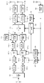
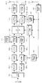
- FIG. 2 is a schematic block diagram illustrating a configuration of a terminal device 1-2 according to the first embodiment of the present invention.
- FIG. 3 is a block diagram showing a configuration of each OFDM signal generator 119-1 to 119-Nt according to the first embodiment of the present invention.
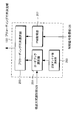
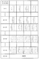
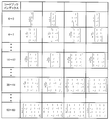
- It is a schematic block diagram which shows the structure of the precoding matrix determination part 133 which concerns on the 1st Embodiment of this invention. It is a figure which shows an example of the code book of this invention. It is a figure which shows an example of the code book of this invention. It is a flowchart explaining the process in the precoding matrix determination part 133 of FIG.
- the codebook is changed according to whether or not the transmission method is OFDM.
- OFDM Orthogonal frequency division multiple access
- a precoding technique different from Rel-10 is adopted. Applies only to OFDM.
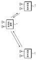
- FIG. 1 is a schematic block diagram showing a configuration of a wireless communication system according to the first embodiment of the present invention.
- the wireless communication system includes terminal apparatuses 1-1 and 1-2 and a base station apparatus 3.
- the terminal device 1-1 is a Rel-10 terminal device that communicates wirelessly with the base station device 3, and the transmission method used for transmission is SC-FDMA or Clustered DFT-S-OFDM.
- the terminal apparatus 1-1 performs CMP type precoding without increasing the CM.
- the terminal device 1-2 is a terminal device of Rel-10 or later that wirelessly communicates with the base station device 3, like the terminal device 1-1, and SC-FDMA, Clustered DFT- as transmission methods for transmission.
- OFDM can be used in addition to S-OFDM.
- one terminal device 1-1, 1-2 is shown, but a plurality of terminal devices 1-1, 1-2 may be provided. Further, the terminal devices 1-1 and 1-2 are collectively referred to as a terminal device 1.
- the transmission process of the terminal device 1-2 will be described with reference to the drawings.
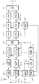
- FIG. 2 is a schematic block diagram showing the configuration of the terminal device 1-2 according to the first embodiment of the present invention.
- the terminal device 1-2 includes an S / P (Serial / Parallel) conversion unit 101 and encoding units 103-1 to 103-L (hereinafter referred to as encoding units 103-1 to 103-L).
- Modulation units 105-1 to 105-L hereinafter, the modulation units 105-1 to 105-L are also collectively referred to as modulation unit 105
- switching units 107-1 to 107-L hereinafter referred to as switching units).
- 107-1 to 107-L is also referred to as switching unit 107), DFT (Discrete Fourier Transform) unit 109-1 to 109-L (hereinafter, DFT unit 109-1 to 109-L is combined to DFT unit) 109), reference signal multiplexing units 111-1 to 111-L (hereinafter, reference signal multiplexing units 111-1 to 111-L are also collectively referred to as reference signal multiplexing unit 111), reference signal generating unit 113, Coding section 115, spectrum mapping sections 117-1 to 117-Nt, OFDM (Orthogonal Frequency Division Multiplex) signal generator 11 -1 to 119-Nt (hereinafter, OFDM signal generators 119-1 to 119-Nt are also collectively referred to as OFDM signal generator 119), transmission antennas 121-1 to 121-Nt (hereinafter referred to as transmission antennas 121-1) ⁇ 121-Nt are also referred to as a transmission antenna 121), a reception antenna 123,
- the data bit sequence transmitted to the base station apparatus 3 is input to the S / P conversion unit 101, subjected to serial-parallel conversion so as to be parallel output of the number of layers (number of ranks, number of streams), and encoded. Input to the sections 103-1 to 103-L.
- L is the number of layers.
- error correction encoding is applied in each of the encoding units 103-1 to 103-L.
- FIG. 2 there are L encoding units 103.
- a configuration may be adopted in which a bit sequence is input to encoding unit 103 and input to modulation units 105-1 to 105-L of each layer by S / P conversion. Good.
- Outputs of the encoding units 103-1 to 103-L are input to the modulation units 105-1 to 105-L.
- Each of the modulation units 105-1 to 105-L converts the bit sequence input from the encoding units 103-1 to 103-L into QPSK (Quadrature) according to information indicating the modulation scheme input from the modulation scheme acquisition unit 127. Phase Shift Keying), 16QAM (Quadrature Amplitude Modulation), 64QAM, 256QAM and other modulation symbols are converted.
- the modulation applied by each of modulation sections 105-1 to 105-L may be the same, or different modulation may be performed in consideration of the reception quality of each layer. In FIG.
- the number of the encoding units 103 and the number of the modulation units 105 are the same, but the encoded bits output from the two encoding units 103 are input to the layer mapping unit as in LTE-A. It may be allocated to ⁇ 4 modulation units 105.
- Modulation sections 105-1 to 105-L input modulation symbols to switching section 107 for each NDFT symbol.
- Switching section 107 inputs a modulation symbol to DFT section 109 or reference signal multiplexing section 111 according to the information input from transmission method identification section 129.
- the information input from the transmission method identification unit 129 is SC-FDMA or Clustered DFT-S-OFDM, it is input to the DFT unit 109, and if it is OFDM, it is input to the reference signal multiplexing unit 111. To do.
- each DFT section 109-1 ⁇ 109-L inputs the N DFT frequency-domain signal to a reference signal multiplexing units 111-1 ⁇ 111-L.
- the reference signal for demodulation is input from the DFT unit 109 or the N DFT pieces each of the signal and the reference signal generator 113 is input from the switching unit 107 (DMRS,
- DMRS De-Modulation Reference Signal
- the outputs of the reference signal multiplexing units 111-1 to 111-L are input to the precoding unit 115.
- the precoding unit 115 multiplies the signal input from the reference signal multiplexing unit 111 by the precoding matrix of Nt rows and L columns according to the information notified from the precoding matrix determination unit 133.
- Nt is the number of transmission antennas.
- the precoding matrix determination unit 133 will be described later.
- the output of precoding section 115 is input to spectrum mapping sections 117-1 to 117-Nt.
- the spectrum mapping units 117-1 to 117-Nt arrange the output of the precoding unit 115 in the system band according to the allocation information (scheduling information) input from the allocation information acquisition unit 131.
- the spectrum mapping applied by each transmission antenna 121 may be the same assignment as shown in FIG. 2 or may be performed independently for each antenna.
- Outputs of spectrum mapping sections 117-1 to 117-Nt are input to corresponding OFDM signal generation sections 119-1 to 119-Nt.
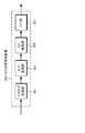
- FIG. 3 is a block diagram showing a configuration of each of the OFDM signal generation units 119-1 to 119-Nt according to the first embodiment of the present invention.
- the IFFT unit 201 applies an inverse fast Fourier transform (Inverse Fast Fourier Transform, IFFT) to each output of the spectrum mapping units 117-1 to 117-Nt, and a conversion from a frequency domain signal to a time domain signal is performed.
- the output of each IFFT unit 201 is input to the CP insertion unit 203, and a CP (Cyclic Prefix) is inserted for each SC-FDMA symbol.
- IFFT inverse Fast Fourier transform
- the SC-FDMA symbol after the CP is inserted is input to the analog processing unit 207 after D / A (digital-analog) conversion is applied by the D / A conversion unit 205.
- the analog processing unit 207 performs analog filtering, up-conversion to a carrier frequency, and the like.
- the output of the analog processing unit 207 is transmitted from each of the transmission antennas 121-1 to 121-Nt.
- control signal receiving unit 125 receives the control information signal transmitted from the base station apparatus 3 of FIG. 1 via the receiving antenna 123, and obtains the obtained control information from the modulation scheme acquisition unit 127 and the transmission scheme identification unit 129. And input to the allocation information acquisition unit 131 and the precoding matrix determination unit 133.
- the allocation information acquisition unit 131 extracts spectrum allocation information from the control information input from the control signal reception unit 125, and inputs the spectrum allocation information to each of the spectrum mapping units 117-1 to 117-Nt.
- the modulation scheme acquisition unit 127 extracts information on the modulation scheme from the control information and inputs the information to the modulation units 105-1 to 105-L.
- the transmission method identification unit 129 identifies the transmission method used in the uplink using the input control information. As an identification method, the base station apparatus 3 may directly notify information indicating the transmission method, or when the modulation method is 64QAM, notify the information indicating the direct transmission method, such as using OFDM as the transmission method. Instead, the transmission method may be grasped by the base station device 3 and the terminal device 1-2.
- the terminal apparatus 1-2 may identify the transmission scheme based on information such as the number of ranks and carrier aggregation.
- Information on the transmission scheme output from the transmission scheme identification unit 129 is input to the switching unit 107 and the precoding matrix determination unit 133.
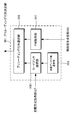
- FIG. 4 is a schematic block diagram showing the configuration of the precoding matrix determination unit 133 according to the first embodiment of the present invention.
- the codebook selection unit 251 selects a plurality of codebooks from the plurality of codebooks according to the number of transmission antennas (number of antenna ports) notified from the transmission antenna number notification unit 253, and further inputs the codebook from the transmission method identification unit 129.
- a predetermined code book is selected according to the transmission method. That is, the code book is selected according to the number of transmission antennas and the transmission method.
- each row of each precoding matrix is an index of transmission antenna 121 (that is, four transmission antennas), and each column represents a rank (the number of streams of different transmission signals transmitted simultaneously).
- indexes 0 to 23 are precoding matrices for rank 1
- indexes 24 to 35 are for rank 2
- indexes 36 to 51 are for rank 3
- index 52 is for rank 4. It is a coding matrix.
- each transmission antenna indicates that one signal (layer) is transmitted (or nothing is transmitted). That is, since the signals are not added to each other at each transmission antenna, the CM (PAPR) of the transmission signal is maintained.
- CM PAPR
- a certain signal (layer) is transmitted from a plurality of antennas, so that transmission antenna diversity gain can be obtained at the receiver.
- the transmission antenna diversity gain is limited.
- each antenna indicates that a plurality of layers to be transmitted are added and transmitted.
- the CM (PAPR) of the transmission signal increases.
- each layer is transmitted from all antennas. As a result, a good transmission antenna diversity gain can be obtained at the receiver.
- the code book selection unit 251 inputs the selected code book to the precoding matrix selection unit 255.
- the control information input from the control signal receiving unit 125 is input to the PMI acquisition unit 257, and only the PMI is extracted.
- the extracted PMI is input to the precoding matrix selection unit 255.
- the precoding matrix selection unit 255 selects a precoding matrix using the codebook input from the codebook selection unit 251 and the index input from the PMI acquisition unit 257. For example, when the code book of FIG. 5 is input from the code book selection unit 251 and 37 is input from the PMI acquisition unit 257, the precoding matrix selection unit 255 Is input to the precoding unit 115 as the output of the precoding matrix determination unit 133.
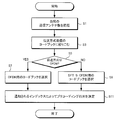
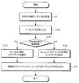
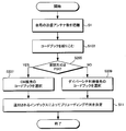
- FIG. 7 is a flowchart for explaining processing in the precoding matrix determination unit 133 in FIG. 4 according to the first embodiment of the present invention.
- the terminal device 1-2 grasps the number of transmission antennas held by the terminal device 1-2 itself (step S1).
- the terminal apparatus 1-2 limits the codebook to be used according to the number of transmission antennas (step S3).
- the codebook is narrowed down to two for OFDM and DFT-S-OFDM.
- the terminal device 1-2 determines whether or not the transmission method used in the next transmission notified from the base station device 3 is OFDM (step S5).
- the terminal device 1-2 selects an OFDM codebook (step S7).
- the terminal device 1-2 selects a codebook for DFT-S-OFDM (step S9). Finally, the terminal apparatus 1-2 determines a precoding matrix to be used for the next transmission based on the selected codebook and the PMI notified from the base station apparatus 3 (step S11), and the next time based on the determined precoding matrix. Is transmitted.
- FIG. 8 is a schematic block diagram showing the configuration of the base station apparatus 3 according to the first embodiment of the present invention.
- the base station apparatus 3 includes receiving antennas 301-1 to 301-Nr (hereinafter, the receiving antennas 301-1 to 301-Nr are also collectively referred to as a receiving antenna 301), reference signal demultiplexing units 303-1 to 303-Nr ( Hereinafter, reference signal demultiplexing units 303-1 to 303-Nr are also collectively referred to as reference signal demultiplexing unit 303), OFDM signal receiving units 305-1 to 305-Nr (hereinafter referred to as OFDM signal receiving units 305-1 to 305-).
- Nr is also referred to as an OFDM signal receiving unit 305), spectrum demapping units 307-1 to 307-Nr, MIMO separation unit 309, switching units 311-1 to 311-L (hereinafter, switching units 311-1 to 311) -L is also referred to as a switching unit 311), IDFT units 313-1 to 313-L (hereinafter, IDFT units 313-1 to 313-L are also collectively referred to as IDFT unit 313), and demodulating unit 315-1 315-L (hereinafter, the demodulation units 315-1 to 315-L are also collectively referred to as a demodulation unit 315), a decoding unit 317-1 to 317-L, P / S conversion unit 319, channel estimation unit 321, modulation scheme determination unit 323, allocation information determination unit 325, transmission scheme determination unit 327, PMI determination unit 329, and control information transmission unit 331 are included. Consists of.
- the signals transmitted from the terminal apparatuses 1-1 and 1-2 are received by the receiving antennas 301-1 to 301-Nr of the base station apparatus 3 in FIG. 8 via the radio channel (propagation path).
- Signals received by the receiving antennas 301-1 to 301-Nr are input to the reference signal separation unit 303 connected to each receiving antenna.
- the reference signal separation unit 303 separates the received signal into a data signal and a reference signal, the data signal is input to the OFDM signal reception unit 305, and the reference signal is input to the channel estimation unit 321.
- the channel estimation unit 321 estimates a channel between the transmission antenna 121 and the reception antenna 301 using the received reception reference signal.
- the obtained channel estimation value is input to MIMO separation section 309, allocation information determination section 325, PMI determination section 329, and modulation scheme determination section 323.
- the modulation scheme determination unit 323 determines a modulation scheme to be used for the next transmission based on the input channel estimation value, and inputs the determined modulation scheme to the control information transmission unit 331.
- the determined modulation scheme is stored in the modulation scheme determination section 323 and input to the demodulation sections 315-1 to 315-L in order to demodulate the signal transmitted by the terminal.
- the allocation information determination unit 325 determines information (allocation information) indicating which terminal apparatus 1-2 uses which frequency for the next transmission based on the input channel estimation value.
- the determined allocation information is stored in the allocation information determination unit 325 and input to the spectrum demapping units 307-1 to 307-Nr for spectrum demapping of the signal transmitted from the terminal.
- FIG. 9 is a schematic block diagram showing the configuration of the OFDM signal receiving unit 305 according to the first embodiment of the present invention.
- Each of the OFDM signal receiving units 305-1 to 305-Nr inputs the input signal to the analog processing unit 401, and performs down-conversion from the carrier frequency to the baseband, analog filtering, and the like.
- the output of the analog processing unit 401 is input to the A / D conversion unit 403, and A / D (analog-digital) conversion is performed.
- the CP removal unit 405 removes the CP added by the terminal devices 1-1 and 1-2, and the FFT unit 407 performs fast Fourier transform (FFT), and performs the transformation. 8 is output to the spectrum demapping units 307-1 to 307-Nr in FIG. 8 connected to each of the frequency domain signals.
- FFT fast Fourier transform
- the spectrum demapping units 307-1 to 307-Nr extract frequency domain signals in the frequency band used for communication based on the allocation information input from the allocation information determination unit 325.
- the frequency domain signals extracted by the spectrum demapping units 307-1 to 307-Nr are input to the MIMO separation unit 309.
- the MIMO separation unit 309 separates the spatially multiplexed signal into L layers using the inputs from the spectrum demapping units 307-1 to 307-Nr and the input from the channel estimation unit 321. Separation methods include spatial filtering (ZF (Zero Forcing), MMSE (Minimum Mean Square Error)), SIC (SuccessiveucInterference Cancellation), V-BLAST (Vertical (Bell Laboratories layered Space Time), MLD (Maximum Likelihood Detection) Such a method may be used.
- ZF Zero Forcing
- MMSE Minimum Mean Square Error
- SIC SuccessessiveucInterference Cancellation
- V-BLAST Vertical (Bell Laboratories layered Space Time
- MLD Maximum Likelihood Detection
- the separated frequency domain signals of each layer are input to the switching units 311-1 to 311-L.
- Each of the switching units 311-1 to 311-L changes the output destination according to the information on the transmission method input from the transmission method determination unit 327. Specifically, when the information input from the transmission method determination unit 327 to the switching unit 311 is SC-FDMA (or Clustered DFT-S-OFDM), the switching unit 311 inputs the input value to the IDFT unit 313. To do. On the other hand, when the information input from the transmission method determination unit 327 to the switching unit 311 is OFDM, the switching unit 311 inputs the input value to the demodulation unit 315.
- SC-FDMA Clustered DFT-S-OFDM
- Each of IDFT sections 313-1 to 313-L performs inverse discrete Fourier transform on the input frequency domain signal to convert it into a time domain signal.
- the obtained time domain signal is input to demodulation sections 315-1 to 315-L.
- Demodulation section 315 converts the received symbol input from IDFT section 313 or switching section 311 into a bit string.
- the output of the demodulation unit 315 is input to the decoding unit 317, and error correction decoding is applied.
- P / S conversion section 319 performs parallel-serial conversion on the outputs of decoding sections 317-1 to 317-L to obtain a transmission data bit sequence.
- the transmission method determination unit 327 in FIG. 8 considers the allowable maximum transmission power of the terminal, the power margin (Power Headroom, PH) for the amplifier, and the like so that the terminal apparatus 1-2 can perform SC-FDMA (or clustered) in the uplink.
- DFT-S-OFDM) or OFDM is determined and input to the PMI determination unit 329 and the control information transmission unit 331.
- the transmission method used for the previous uplink transmission is also stored and input to the switching unit 311 for use in reception processing.
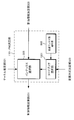
- FIG. 10 is a schematic block diagram showing the configuration of the PMI determination unit 329 according to the first embodiment of the present invention.
- the processing of the PMI determination unit 329 will be described with reference to FIG.
- An input from the transmission method determination unit 327 is input to the code book selection unit 501.
- the code book selection unit 501 selects a code book according to the input from the transmission method determination unit 327 and the number of transmission antennas of the terminal device 1-2 notified by the transmission antenna number notification unit 503. For example, when the number of transmission antennas of the terminal device 1-2 is 4 and the transmission method is SC-FDMA (or Clustered DFT-S-OFDM), FIG. 5 shows a code book that does not increase the CM of the transmission signal. Use the described codebook.
- SC-FDMA Clustered DFT-S-OFDM
- the code book shown in FIG. 6 is used.
- the code book selection unit 501 selects a code book on the premise of CM maintenance, and the transmission method is CM.
- a codebook capable of obtaining a good transmission antenna gain is selected without assuming CM maintenance.
- the code book selected by the code book selection unit 501 is input to the index selection unit 505.
- the index selection unit 505 also receives allocation information from the allocation information determination unit 325 and a channel estimation value from the channel estimation unit 321, and selects an optimal PMI from the codebook according to the channel to be used. For example, when the code book of FIG. 5 is input from the code book selection unit 501, any precoding matrix is selected and its index is determined in consideration of the channel estimation value, the amount of data to be transmitted, and the like. .
- the output of the index selection unit 505 is input as the output of the PMI determination unit 329 to the control information transmission unit 331 in FIG.
- the control information transmission unit 331 the PMI input from the PMI determination unit 329, the information regarding the transmission method input from the transmission method determination unit 327, the information regarding the modulation method input from the modulation method determination unit 323, and the allocation information determination unit 325
- the information including the spectrum allocation information (allocation information) input from, and other control information not shown is transmitted to the terminal device 1-2.
- FIG. 11 is a flowchart illustrating processing in the PMI determination unit 329 of FIG. 10 according to the first embodiment of the present invention.
- the base station apparatus 3 grasps the number of transmission antennas possessed by the target terminal apparatus 1-2 (step T1). It is assumed that the number of transmission antennas is notified in advance from the terminal device 1-2 before performing communication.
- the base station apparatus 3 limits the codebook to be used according to the number of transmission antennas (step T3). At this stage, the codebook is narrowed down to two for OFDM and DFT-S-OFDM.
- the base station apparatus 3 determines whether the transmission method used by the terminal apparatus 1-2 in the next transmission is OFDM or DFT-S-OFDM (step T5).
- the base station apparatus 3 selects an OFDM codebook (step T7).
- the base station apparatus 3 selects a codebook for DFT-S-OFDM (step T9).
- the base station apparatus 3 determines a precoding matrix to be used for the next transmission using the channel estimation value, the allocation information, and the selected codebook (step T11), and sets the index of the precoding matrix. PMI.
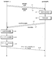
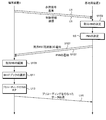
- FIG. 12 is a sequence chart for explaining processing of the terminal device 1-2 and the base station device 3 according to the first embodiment of the present invention.
- the terminal apparatus 1-2 transmits a reference signal and control information to the base station apparatus 3 (step U1), so that the base station apparatus 3 determines a transmission method to be used for the next uplink transmission (step U3). ),
- the PMI is determined by the PMI determination unit 329 in FIG. 10 (step U5).
- the determined transmission method information and PMI used for the next uplink transmission are notified from the base station apparatus 3 to the terminal apparatus 1-2 (step U7).
- the terminal device 1-2 recognizes the transmission method used for the next uplink transmission from the transmission method information (step U9), and the precoding matrix determination unit 133 in FIG. A coding matrix is determined (step U13).
- the terminal device 1-2 multiplies the data by the determined precoding matrix and performs data transmission (step U15).
- the codebook to be used is selected not only according to the number of transmission antennas (the number of antenna ports) but also according to the transmission method. Therefore, even if the same PMI is notified in a communication system in which a plurality of transmission methods are defined, different precoding can be performed depending on the transmission method used. As a result, since precoding suitable for each transmission method can be performed, it is possible to increase throughput while maintaining coverage as compared with the case where the same precoding is used. Further, since the code book is selected depending on the selected transmission method, it is not necessary to add information on which code book is selected. As a result, the amount of downlink control information is not increased.
- the codebook is changed depending on whether it is SC-FDMA or Clustered.
- the transmission scheme with a low CM is SC-FDMA and Clustered DFT-S-OFDM
- the transmission scheme with a high CM is OFDM.
- Clustered DFT-S-OFDM is a transmission scheme in which CM is higher than SC-FDMA
- Clustered DFT-S-OFDM is used as a transmission scheme with high CM
- SC-FDMA and Clustered DFT-S-OFDM are used. It is also possible to use different codebooks.
- SC-FDMA is handled as a transmission scheme with a low CM
- Clustered DFT-S-OFDM is handled as a transmission scheme with a high CM.
- FIG. 13 is a schematic block diagram showing a communication device configuration of the terminal device 1 according to the second embodiment of the present invention. Since the configuration is almost the same as the transmitter configuration of FIG. 2 shown in the first embodiment, only different blocks will be described.
- the switching units 107-1 to 107-L do not exist. This is because both the SC-FDMA and Clustered DFT-S-OFDM require DFT processing by the DFT unit 109.
- the switching unit 107 exists as in the first embodiment. After the DFT unit 109, transmission is performed from the antenna unit by the same processing as in the first embodiment.
- control information received by the control signal receiving unit 125 is input to the allocation information acquiring unit 131, the precoding matrix determining unit 601, and the modulation scheme acquiring unit 127.
- the allocation information acquisition unit 131 extracts allocation information (scheduling information) from the input control information and inputs it to the spectrum mapping units 117-1 to 117-Nt and the precoding matrix determination unit 601. Spectrum mapping sections 117-1 to 117-Nt arrange the spectrum input from precoding section 115 at a frequency within the system band based on the input allocation information.
- FIG. 14 is a schematic block diagram showing the configuration of the precoding matrix determination unit 601 according to the second embodiment of the present invention.
- the input from the allocation information acquisition unit 131 is input to the code book selection unit 651.
- the codebook selection unit 651 a plurality of codebooks are selected according to the number of transmission antennas (number of antenna ports) of the terminal device 1 notified from the transmission antenna number notification unit 253, and further the allocation input from the allocation information acquisition unit 131 A predetermined codebook is selected based on the information.
- the allocation information input from the allocation information acquisition unit 131 is continuously arranged, that is, when the transmission method is SC-FDMA, a codebook giving priority to maintaining the CM as shown in FIG.
- a codebook giving priority to maintaining the CM as shown in FIG. 6
- a codebook that can obtain a good transmission antenna gain as shown in FIG. 6 is selected.
- the selected codebook is input to the precoding matrix selection unit 255.
- Clustered DFT-S-OFDM is characterized in that CM increases as the number of clusters increases. Therefore, it is conceivable to prepare a code book according to the number of clusters of Clustered DFT-S-OFDM.
- CM increases as the number of clusters increases. Therefore, it is conceivable to prepare a code book according to the number of clusters of Clustered DFT-S-OFDM.
- the transmission method is SC-FDMA or Clustered DFT-S-OFDM with 2 clusters
- a codebook that does not increase CM is used, and when the number of clusters is 3 or more, transmit antenna diversity is used.
- Changing the code book having a high gain is also included in the present invention.
- two codebooks are prepared. However, three or more codebooks may be prepared in the system according to the number of clusters of Clustered DFT-S-OFDM.
- the PMI acquisition unit 257 extracts the PMI from the control information input from the control signal reception unit 125 and inputs the PMI to the precoding matrix selection unit 255.
- the precoding matrix selection unit 255 selects a precoding matrix corresponding to the PMI in the codebook input from the codebook selection unit 651 and inputs it to the precoding unit 115 as an output of the precoding matrix determination unit 601. .
- FIG. 15 is a flowchart for explaining processing in the precoding matrix determination unit 601 in FIG. 14 according to the second embodiment of the present invention.
- the same number was attached
- the terminal device 1 grasps the number of transmission antennas held by the terminal device 1 itself (step S1).
- the terminal device 1 limits the codebook to be used according to the number of transmission antennas (step S103).
- the terminal device 1 determines whether the frequency arrangement is a continuous arrangement (step S105). When the frequency arrangement is a continuous arrangement (step S105: YES), the terminal device 1 selects a codebook for SC-FDMA (step S107).
- step S105 When the frequency arrangement is not continuous arrangement (step S105: NO), the terminal device 1 selects a codebook for Clustered DFT-S-OFDM (step S109). Finally, the terminal apparatus 1 determines a precoding matrix to be used for the next transmission based on the selected codebook and the PMI notified from the base station apparatus 3 (step S11), and the next transmission is performed based on the determined precoding matrix. To do.
- FIG. 16 is a schematic block diagram showing a receiver configuration of the base station apparatus 3 according to the second embodiment of the present invention. Since the configuration is almost the same as the configuration of FIG. 8 shown in the first embodiment, only different blocks will be described. Since OFDM does not exist as a transmission method, switching units 311-1 to 311-L do not exist as in the terminal configuration, and the output of MIMO separation unit 309 is input to IDFT units 313-1 to 313-L.
- FIG. 17 is a schematic block diagram showing the configuration of the PMI determination unit 701 according to the second embodiment of the present invention.
- the allocation information input from the allocation information determination unit 325 is input to the code book selection unit 801 and the index selection unit 505.
- the codebook selection unit 801 selects a plurality of codebooks from among the plurality of codebooks according to the number of transmission antennas (number of antenna ports) of the terminal device 1 notified from the transmission antenna number notification unit 503, and further determines allocation information.
- a predetermined code book is selected according to the allocation information input from the unit 325.
- the allocation information is continuous allocation (that is, the transmission scheme is SC-FDMA)
- a codebook composed of precoding matrices giving priority to CM maintenance as shown in FIG. 5 is selected
- allocation information is discontinuous allocation
- the transmission method is Clustered (DFT-S-OFDM)
- a codebook composed of a precoding matrix giving priority to transmission antenna diversity gain as shown in FIG. 6 is selected.
- the selected code book is input to the index selection unit 505.
- the index selection unit 505 uses the channel estimation value input from the channel estimation unit 321, the code book input from the code book selection unit 801, and the allocation information input from the allocation information determination unit 325. Which precoding matrix is to be used for uplink transmission is input to the control information transmission unit 331.
- FIG. 18 is a flowchart for explaining processing in the PMI determination unit 701 in FIG. 17 according to the second embodiment of the present invention.
- the same number is attached
- the base station device 3 grasps the number of transmission antennas of the target terminal device 1 (step T1). It is assumed that the number of transmission antennas is notified in advance from the terminal device 1 before performing communication.
- the base station apparatus 3 limits the codebook to be used according to the number of transmission antennas (step T103).
- the base station apparatus 3 determines whether the frequency arrangement is a continuous arrangement (step T105). When the frequency arrangement is a continuous arrangement (step T105: YES), the base station apparatus 3 selects a codebook for SC-FDMA (step T107).
- the base station apparatus 3 selects a codebook for Clustered DFT-S-OFDM (step T109). Finally, the base station apparatus 3 determines a precoding matrix to be used for the next transmission using the channel estimation value, the allocation information, and the selected codebook (step T11), and sets the index of the precoding matrix. PMI.
- FIG. 19 is a sequence chart illustrating processing of the terminal device 1 and the base station device 3 according to the second embodiment of the present invention.
- the terminal apparatus 1 transmits a reference signal and control information to the base station apparatus 3 (step U1), so that the base station apparatus 3 determines an allocation RB to be used for the next uplink transmission (step U103).
- the PMI is determined by the PMI determination unit 701 in FIG. 17 (step U5).
- the determined allocation RB (frequency) and PMI used for the next uplink transmission are notified from the base station apparatus 3 to the terminal apparatus 1 (step U107).
- the terminal apparatus 1 recognizes the allocation RB to be used for the next uplink transmission from the transmission scheme information (step U109), the codebook selection (step U11), the precoding matrix by the precoding matrix determination unit 601 in FIG. Is determined (step U13).
- the terminal device 1 multiplies the data by the determined precoding matrix and performs data transmission (step U15).
- Clustered DFT-S-OFDM increases CM by precoding.
- a plurality of precoding matrices for transmission of a predetermined rank in the codebook are statistically constant in the amount of increase in CM, but precoding has a difference in the amount of increase in CM.
- the matrix may be converted into a code book. For example, in FIG. 6, for rank 2 precoding, twelve indexes 4 to 15 are prepared, and not all of the CMP type, but four of the twelve are replaced with the CMP type as a codebook. 8 use a codebook in which the CM increases. If such a code book is prepared, for example, the base station apparatus 3 sets a precoding matrix that does not increase the CM of the transmission signal of the terminal apparatus 1 by the magnitude of the PH notified to the base station apparatus 3 by the terminal apparatus 1. You can choose.
- the PMI determination unit 701 of the present embodiment operates to perform precoding to maintain CM when spectrum allocation is continuous, and performs precoding when spectrum allocation is discontinuous. Regardless, since the CM is high to some extent, an increase in the CM is allowed and the precoding is performed so that the transmission antenna diversity gain is increased. As a result, since the transmission characteristics of the terminal apparatus 1 in which deterioration of CM is not important can be improved while maintaining the coverage as compared with the case of using a codebook composed only of a precoding matrix that maintains CM, the cell Throughput can be increased.
- the precoding codebook is selected depending on whether the transmission signal is SC-FDMA or Clustered DFT-S-OFDM, but SC-FDMA uses precoding that maintains CM.
- SC-FDMA uses precoding that maintains CM.
- a codebook that consists of a precoding matrix that maintains CM and a pre-priority that prioritizes transmit antenna diversity gain, depending on the spectrum mapping state. It is good also as a structure which selects the code book comprised from a coding matrix.
- 20A, 20B, 21A, and 21B are schematic diagrams of system bands in which clusters are arranged.
- a clustered DFT-S-OFDM composed of two clusters
- the influence of radiation outside the system band on the spectrum mask will increase, so power It is necessary to suppress the transmission.
- transmission is performed with the average transmission power lowered, so that amplification can be performed within the linear region of the amplifier even if the peak power is increased. Therefore, a codebook composed of precoding matrices giving priority to transmit antenna diversity gain is selected.
- a codebook composed of precoding matrices giving priority to transmit antenna diversity gain is selected, and the value of the distance between clusters is a predetermined value. If it is smaller, it is also included in the present invention to select a codebook composed of precoding matrices that maintain CM.
- the use band is wide with respect to the system band as shown in FIG. 21A, the probability that the distance between the clusters is narrow is high, and when the use band is narrow with respect to the system band as shown in FIG. Is likely to become wide. Therefore, a configuration may be adopted in which the used bandwidth with respect to the system bandwidth is calculated and the codebook to be used is selected based on the ratio.
- the code book is changed according to the modulation method.
- the CM differs depending on the transmission method, the case where the precoding method is changed depending on the transmission method has been described.
- the CM changes not only when the transmission method changes.
- CM Physical Uplink Shared CHannel
- PUCCH Physical Uplink Control an CHannel
- FIG. 22 is a schematic block diagram showing a transmitter configuration of the terminal device 1 according to the third embodiment of the present invention. Since the configuration is almost the same as the transmitter configuration of FIG. 13 shown in the second embodiment, only different blocks will be described. The difference is the input to the precoding matrix determination unit 901 and the internal processing, and only this point will be described.
- the codebook to be selected differs depending on spectrum allocation (whether SC-FDMA or ClusteredFTDFT-S-OFDM), so the output of the allocation information acquisition unit 131 is sent to the precoding matrix determination unit 901. It was entered.
- information on the modulation scheme is input from the modulation scheme acquisition section 127 to the precoding matrix determination section 901.
- FIG. 23 is a schematic block diagram showing the configuration of the precoding matrix determination unit 901 according to the third embodiment of the present invention.
- An input from the modulation scheme acquisition unit 127 is input to the codebook selection unit 1001.
- the codebook selection unit 1001 selects a plurality of codebooks from among a plurality of codebooks according to the number of transmission antennas (number of antenna ports) of the terminal device 1 notified from the transmission antenna number notification unit 253, and further acquires a modulation scheme.
- a predetermined code book is selected according to the modulation method input from the unit 127.
- the codebook giving priority to maintaining the CM as shown in FIG. 5 is selected.
- the modulation method input from the modulation method acquisition unit 127 is a high-CM method such as 16QAM, 64QAM having a higher CM than 16QAM, or 256QAM, a good transmission antenna gain as shown in FIG.
- a codebook that can obtain The selected codebook is input to the precoding matrix selection unit 255.
- 16QAM is regarded as a modulation scheme with high CM.
- 64QAM or more is a modulation scheme with high CM.
- the input from the control signal receiving unit 125 is input to the PMI acquisition unit 257, the PMI is extracted from the control information, and the obtained PMI is input to the precoding matrix selection unit 255.
- the precoding matrix selection unit 255 selects a precoding matrix corresponding to the PMI in the codebook input from the codebook selection unit 1001, and inputs it to the precoding unit 115 as an output of the precoding matrix determination unit 901. .
- FIG. 24 is a flowchart for explaining processing in the precoding matrix determination unit 901 in FIG. 23 according to the third embodiment of the present invention.
- the same number is attached
- the terminal device 1 grasps the number of transmission antennas held by the terminal device 1 itself (step S1).
- the terminal device 1 limits the codebook to be used according to the number of transmission antennas (step S103).
- the terminal device 1 determines whether the modulation method is PSK (step S205). If the modulation method is PSK (step S205: YES), the terminal device 1 selects a code book for CM maintenance (step S207).
- the terminal apparatus 1 selects a diversity gain priority codebook (step S209). Finally, the terminal apparatus 1 determines a precoding matrix to be used for the next transmission based on the selected codebook and the PMI notified from the base station apparatus 3 (step S11), and performs the next transmission based on the determined precoding matrix. Do.
- FIG. 25 is a schematic block diagram showing a receiver configuration of the base station apparatus 3 according to the third embodiment of the present invention.
- PMI determination section 1101 is also input from modulation scheme determination section 323 in addition to the channel estimation value input from channel estimation section 321 and the allocation information input from allocation information determination section 325.
- the internal processing of the PMI determination unit 1101 will be described with reference to FIG.
- FIG. 26 is a schematic block diagram showing the configuration of the PMI determination unit 1101 according to the third embodiment of the present invention.
- Information input from the modulation scheme determination unit 323 is input to the codebook selection unit 1201.
- the codebook selection unit 1201 selects a plurality of codebooks from among a plurality of codebooks according to the number of transmission antennas (number of antenna ports) of the terminal device 1 notified from the transmission antenna number notification unit 503, and further determines a modulation scheme.
- a predetermined code book is selected according to the modulation method input from the unit 323. That is, if the modulation scheme input from the modulation scheme determination unit 323 is a scheme with a low CM (for example, BPSK or QPSK), a codebook composed of precoding matrices prioritizing CM maintenance as shown in FIG. 5 is selected. If the modulation scheme is a scheme with a high CM (for example, 64QAM or 256QAM), a codebook capable of obtaining a good transmission antenna gain as shown in FIG. 6 is selected.
- CM for example, BPSK or QPSK
- the selected codebook is input to the index selection unit 505.
- the index selection unit 505 uses the channel estimation value input from the channel estimation unit 321, the code book input from the code book selection unit 1201, and the allocation information input from the allocation information determination unit 325. Which precoding matrix is to be used for uplink transmission is input to the control information transmission unit 331.
- the PMI determination unit 1101 of the present embodiment operates to perform precoding to maintain CM when using a modulation scheme with low CM, and performs precoding when using a modulation scheme with high CM. Regardless, since the CM is high to some extent, the CM is allowed to increase, and precoding is performed so as to increase the transmission antenna diversity gain.
- FIG. 27 is a flowchart for explaining processing in the PMI determination unit 1101 in FIG. 26 according to the third embodiment of the present invention.
- the same number is attached
- the base station device 3 grasps the number of transmission antennas of the target terminal device 1 (step T1). It is assumed that the number of transmission antennas is notified in advance from the terminal device 1 before performing communication.
- the codebook to be used is limited according to the number of transmission antennas (step T103).
- the base station apparatus 3 determines whether the modulation method is PSK (step T205). When the modulation method is PSK (step T205: YES), the base station apparatus 3 selects a CM maintenance codebook (step T207).
- the base station apparatus 3 selects a diversity gain priority codebook (step T209). Finally, the base station apparatus 3 determines a precoding matrix to be used for the next transmission using the channel estimation value, the allocation information, and the selected codebook (step T11), and sets the index of the precoding matrix. PMI.
- FIG. 28 is a sequence chart for explaining processing of the terminal device 1 and the base station device 3 according to the third embodiment of the present invention.
- the terminal apparatus 1 transmits a reference signal and control information to the base station apparatus 3 (step U1), so that the base station apparatus 3 determines an MCS to be used for the next uplink transmission (step U203).
- the PMI is determined by the 26 PMI determination units 1101 (step U5).
- the determined MCS information and PMI used for the next uplink transmission are notified from the base station apparatus 3 to the terminal apparatus 1 (step U207).
- the terminal device 1 recognizes the MCS to be used for the next uplink transmission from the MCS information (step U209), the codebook selection (step U11), and the precoding matrix determination by the precoding matrix determination unit 901 in FIG. (Step U13).
- the terminal device 1 multiplies the data by the determined precoding matrix and performs data transmission (step U15).
- a high-order multilevel modulation scheme that is, 64QAM or the like is often used for transmission.
- a precoding matrix that increases the transmission antenna diversity gain is selected, so that transmission characteristics are improved compared to the case where precoding is performed while maintaining CM in all terminal apparatuses 1. can do. That is, this embodiment is particularly effective in fractional TPC.
- the above embodiments can be realized in combination.
- the modulation multilevel number is high and the transmission method is Clustered DFT-S-OFDM
- precoding without maintaining CM is performed, for example, the modulation multilevel number is high, or the transmission method is OFDM or Clustered DFT-S.
- precoding without maintaining CM is also included in the present invention.
- the program that operates in the terminal device 1 and the base station device 3 related to the present invention is a program (a program that causes a computer to function) that controls the CPU and the like so as to realize the functions of the above-described embodiments related to the present invention.
- Information handled by these devices is temporarily stored in the RAM at the time of processing, then stored in various ROMs and HDDs, read out by the CPU, and corrected and written as necessary.
- a recording medium for storing the program a semiconductor medium (for example, ROM, nonvolatile memory card, etc.), an optical recording medium (for example, DVD, MO, MD, CD, BD, etc.), a magnetic recording medium (for example, magnetic tape, Any of a flexible disk etc. may be sufficient.
- the processing is performed in cooperation with the operating system or other application programs.
- the functions of the invention may be realized.
- the program when distributing to the market, can be stored in a portable recording medium for distribution, or transferred to a server computer connected via a network such as the Internet.
- the storage device of the server computer is also included in the present invention.
- LSI which is an integrated circuit.
- Each functional block of the terminal device 1 and the base station device 3 may be individually chipped, or a part or all of them may be integrated into a chip.
- the method of circuit integration is not limited to LSI, and may be realized by a dedicated circuit or a general-purpose processor. Either hybrid or monolithic may be used. Some of the functions may be realized by hardware and some by software.
- an integrated circuit based on the technology can be used.
- the embodiment of the present invention has been described in detail with reference to the drawings. However, the specific configuration is not limited to this embodiment, and the design and the like within the scope not departing from the gist of the present invention are also claimed. Included in the range.
- the present invention can be used in a mobile communication system in which a mobile phone device is a terminal device 1.
Landscapes
- Engineering & Computer Science (AREA)
- Computer Networks & Wireless Communication (AREA)
- Signal Processing (AREA)
- Physics & Mathematics (AREA)
- Mathematical Physics (AREA)
- Power Engineering (AREA)
- Radio Transmission System (AREA)
- Mobile Radio Communication Systems (AREA)
Abstract
セルラシステムでプリコーディングの性能を十分に活かすことのできる新たなプリコーディングを導入することにより、スループットを向上させる。複数の送信アンテナを備え、送信信号に対してプリコーディングを行なう端末装置であって、前記送信アンテナの数および前記送信アンテナの数以外の送信パラメータに基づいて、複数のプリコーディング行列を含む複数のコードブックからいずれか一つのコードブックを選択するコードブック選択部251と、PMI(Precoding Matrix Indicator)に基づいて、前記選択したコードブックからいずれか一つのプリコーディング行列を選択するプリコーディング行列選択部255と、を備える。
Description
本発明は、プリコーディングを行なった信号を複数の送信アンテナを用いて送信する技術に関する。
3GPP(3rd Generation Partnership Project)で標準化が行なわれた無線通信システムであるLTE(Long Term Evolution)リリース8(Rel-8)では、最大20MHzの帯域を利用して100Mbps以上の高速通信を行なうことが可能である。LTE Rel-8の下りリンク(基地局装置から端末装置への通信)における伝送方式としては、周波数選択フェージングに強い耐性を持つこと、MIMO(Multiple Input Multiple Output)伝送と親和性が高いこと、等の理由からOFDM(直交周波数分割多重、Orthogonal Frequency Division Multiplexing)が採用されている。
LTE Rel-8の下りリンクでは、最大4アンテナポート(複数の送信アンテナから同一の信号を送信する場合、それらのアンテナをまとめてアンテナポートと定義する)を用いたMIMO伝送が可能である。受信機での信号分離能力を上げるため、瞬時の伝搬路に応じて、適切なプリコーディング行列を送信信号に乗算して送信を行なう、閉ループ型MIMOが採用されている。下りリンクにおける適切なプリコーディング行列は、受信機である端末装置(移動端末装置、移動局装置、端末とも称する)しか把握できないため、端末装置が適切なプリコーディング行列を基地局装置(制御局装置とも称する)に通知する必要がある。ここで、端末装置から基地局装置への通知情報を削減するため、LTEではコードブックベースのプリコーディング行列を用いることになっている。端末装置はコードブック化されたプリコーディング行列の中から最適なプリコーディング行列を選択し、そのインデックス(PMI、Precoding Matrix Indicator)を基地局装置に通知する仕組みになっている。
一方、上りリンク(端末装置から基地局装置への通信)では、端末装置のコストや規模が重要である。OFDMはPAPR(Peak to Average Power Ratio、ピーク対平均電力比)あるいはCM(Cubic Metric、PAPRと同様に信号波形の平均電力に対するピーク電力の標準偏差で示されるピーク電力の大きさを表す指標)が高く、線形領域の広い電力増幅器が必要となるため、消費電力が大きくなってしまい、上りリンクの伝送に向かない。そこで、LTE Rel-8の上りリンクでは、CMの低いSC-FDMA(Single Carrier Frequency Division Multiple Access)が採用されている。
3GPPでは、LTE Rel-10以降の規格をLTE-A(LTE-Advanced)と呼び、標準化を行なっている。LTE Rel-8の上りリンクではMIMO伝送が仕様化されなかったが、Rel-10では仕様化されており、最大4アンテナポートを用いたSU-MIMO(Single User MIMO)伝送が可能である。4アンテナポートを用いる場合、各アンテナポートからそれぞれ異なるデータを送信することで、レイヤ数(ランク、ストリーム数とも呼ぶ)4の伝送を行なうことが可能である。伝送にはコードブックベースのプリコーディングを行なうことになっており、基地局装置は最良の伝送特性が得られるプリコーディング行列をコードブックの中から選択し、端末装置に通知する。ここでコードブックは、使用アンテナポート数毎に異なるコードブックが用意されており、例えばRel-10では、使用アンテナポート数が1、2、4用のコードブックがそれぞれ用意されている。
またアンテナポート数が4のLTE Rel-8の下りリンクでは、プリコーディング行列としてHouse Holder(HH)行列が採用されたのに対し、Rel-10の上りリンクでは非特許文献1に記載されているように、CMP(CM Preserving)型のプリコーディング行列が採用されている。これは、HH行列を用いたプリコーディングの場合、複数の信号(レイヤ)の加算を行なった信号を、各送信アンテナポートから送信するため、CM(PAPR)が増加してしまうのに対し、CMP型の行列を用いたプリコーディングの場合、各アンテナポートからは1つの信号(レイヤ)しか送信されないため、元々のCMを維持できるためである。しかしながら、CMP型のプリコーディングは、CMを維持するという制限があるため、HH行列を用いた場合ほどの伝送特性は見込めない。また3GPPにおいて、非特許文献2のように、ランク3伝送に関して、同一コードブック内にCMP型のプリコーディングと、CMを維持しないCMF(CM Friendly)型のプリコーディングを共存させるコードブックも提案されたが、採用には至らなかった。
また、LTE-10のRAN(Radio Access Network)1の仕様では、MIMO伝送に加えて、Clustered DFT-S-OFDM(Discrete Fourier Transform Spread OFDM)が採用されている。SC-FDMAがシングルキャリアスペクトルを任意の周波数に連続的に配置するのに対し、Clustered DFT-S-OFDMでは、SC-FDMAのスペクトルを2分割し、任意の周波数に不連続に割り当てることが可能である。
3GPP TS36.211 V10.1.0
R1-100655、"Uplink Rank-3 Codebook Design for LTE-Advanced"、LGE
LTE-10では、CMを増加させないことを優先し、CMP型の行列を用いたプリコーディングが採用されている。しかし、CMが重要なのはセルエッジの端末装置であり、セル中央の端末装置のようなCMが重要でない端末装置は、プリコーディング技術が本来持つ性能を十分活かしきれていない。
本発明は、このような事情に鑑みてなされたものであり、セルラシステムでプリコーディングの性能を十分に活かすことのできる新たなプリコーディングを導入することにより、スループットを向上させることができる端末装置、基地局装置、プログラムおよび集積回路を提供することを目的とする。
(1)上記の目的を達成するために、本発明は、以下のような手段を講じた。すなわち、本発明の端末装置は、複数の送信アンテナを備え、送信信号に対してプリコーディングを行なう端末装置であって、前記送信アンテナの数および前記送信アンテナの数以外の送信パラメータに基づいて、複数のプリコーディング行列を含む複数のコードブックからいずれか一つのコードブックを選択するコードブック選択部と、PMI(Precoding Matrix Indicator)に基づいて、前記選択したコードブックからいずれか一つのプリコーディング行列を選択するプリコーディング行列選択部と、を備えることを特徴とする。
このように、送信アンテナの数および送信アンテナの数以外の送信パラメータに基づいて、複数のプリコーディング行列を含む複数のコードブックからいずれか一つのコードブックを選択し、PMI(Precoding Matrix Indicator)に基づいて、前記選択したコードブックからいずれか一つのプリコーディング行列を選択するので、PMIが同じであっても、送信アンテナの数以外の送信パラメータに応じて、異なるプリコーディングを行なうことができる。その結果、送信アンテナの数以外の送信パラメータに適したプリコーディングを行なうことができ、常に同一のプリコーディングを使用する場合と比較し、カバレッジを維持しつつ、スループットを増加させることができる。また、選択された送信アンテナの数以外の送信パラメータに依存してコードブックが選択されるため、どのコードブックを選択するのかという情報を追加する必要がなくなる。このため、下りリンク制御情報量が増加することを回避することが可能となる。
(2)また、本発明の端末装置において、前記送信パラメータは、送信信号のCM(Cubic Metric)の大きさであることを特徴とする。
このように、送信パラメータは、送信信号のCM(Cubic Metric)の大きさであるので、CMの大きさに適したプリコーディングを行なうことができる。このため、常に同一のプリコーディングを使用する場合と比較し、カバレッジを維持しつつ、スループットを増加させることができる。
(3)また、本発明の端末装置において、前記送信パラメータは、伝送方式を示す情報であることを特徴とする。
このように、送信パラメータは、伝送方式を示す情報であるので、伝送方式に適したプリコーディングを行なうことができる。このため、常に同一のプリコーディングを使用する場合と比較し、カバレッジを維持しつつ、スループットを増加させることができる。
(4)また、本発明の端末装置において、前記送信パラメータは、スペクトルの割り当てパターンを示す情報であることを特徴とする。
このように、送信パラメータは、スペクトルの割り当てパターンを示す情報であるので、CMを維持するプリコーディング行列のみから構成されるコードブックを用いる場合と比較して、カバレッジを維持しつつ、CMの劣化が重要ではない端末装置の伝送特性を改善することができる。その結果、セルスループットを増加させることができる。
(5)また、本発明の端末装置において、前記送信パラメータは、変調方式を示す情報であることを特徴とする。
このように、送信パラメータは、変調方式を示す情報であるので、例えば、セル中央の端末装置ほど高い電力で受信されるように送信電力制御(Transmit Power Control、TPC)を行なうフラクショナルTPCにおいては、セルエッジの端末装置の信号は低い電力で受信されるため、低多値数の変調方式が伝送に用いられる。この場合、CMを維持したプリコーディングを行なうことができ、伝送特性を劣化させることがない。一方、セル中央の端末装置の信号は高い電力で受信されるため、高次の多値数の変調方式が用いられる。この場合、送信アンテナダイバーシチ利得が大きくなるプリコーディング行列を選択するため、全端末装置にCMを維持したプリコーディングを行なう場合と比較して、伝送特性を改善することができる。
(6)また、本発明の端末装置において、前記コードブック選択部は、送信信号のCM(Cubic Metric)を維持する複数のプリコーディング行列を含むコードブックまたは良好な送信アンテナ利得が得られる複数のプリコーディング行列を含むコードブックのいずれか一方を選択することを特徴とする。
このように、送信信号のCM(Cubic Metric)を維持する複数のプリコーディング行列を含むコードブックまたは良好な送信アンテナ利得が得られる複数のプリコーディング行列を含むコードブックのいずれか一方を選択するので、PMIが同じであっても、送信アンテナの数以外の送信パラメータに応じて、異なるプリコーディングを行なうことができる。その結果、送信アンテナの数以外の送信パラメータに適したプリコーディングを行なうことができ、常に同一のプリコーディングを使用する場合と比較し、カバレッジを維持しつつ、スループットを増加させることができる。また、選択された送信アンテナの数以外の送信パラメータに依存してコードブックが選択されるため、どのコードブックを選択するのかという情報を追加する必要がなくなる。このため、下りリンク制御情報量が増加することを回避することが可能となる。
(7)また、本発明の基地局装置は、プリコーディングを行なった信号を複数の送信アンテナを用いて送信する端末装置と無線通信を行なう基地局装置であって、前記端末装置の送信アンテナの数および前記送信アンテナの数以外の送信パラメータに基づいて、複数のプリコーディング行列を含む複数のコードブックからいずれか一つのコードブックを選択するコードブック選択部と、前記選択したコードブックからいずれか一つのプリコーディング行列を選択し、前記選択したプリコーディング行列を示すインデックスを選択するインデックス選択部と、を備え、前記選択したインデックスを示す情報を、前記端末装置に送信することを特徴とする。
このように、送信アンテナの数および送信アンテナの数以外の送信パラメータに基づいて、複数のプリコーディング行列を含む複数のコードブックからいずれか一つのコードブックを選択し、PMI(Precoding Matrix Indicator)に基づいて、前記選択したコードブックからいずれか一つのプリコーディング行列を選択するので、PMIが同じであっても、送信アンテナの数以外の送信パラメータに応じて、異なるプリコーディングを行なうことができる。その結果、送信アンテナの数以外の送信パラメータに適したプリコーディングを行なうことができ、常に同一のプリコーディングを使用する場合と比較し、カバレッジを維持しつつ、スループットを増加させることができる。また、選択された送信アンテナの数以外の送信パラメータに依存してコードブックが選択されるため、どのコードブックを選択するのかという情報を追加する必要がなくなる。このため、下りリンク制御情報量が増加することを回避することが可能となる。
(8)また、本発明のプログラムは、複数の送信アンテナを備え、送信信号に対してプリコーディングを行なう端末装置を制御するプログラムであって、前記送信アンテナの数および前記送信アンテナの数以外の送信パラメータに基づいて、複数のプリコーディング行列を含む複数のコードブックからいずれか一つのコードブックを選択する処理と、PMI(Precoding Matrix Indicator)に基づいて、前記選択したコードブックからいずれか一つのプリコーディング行列を選択する処理と、を含む一連の処理を、コンピュータに実行させることを特徴とする。
このように、送信アンテナの数および送信アンテナの数以外の送信パラメータに基づいて、複数のプリコーディング行列を含む複数のコードブックからいずれか一つのコードブックを選択し、PMI(Precoding Matrix Indicator)に基づいて、前記選択したコードブックからいずれか一つのプリコーディング行列を選択するので、PMIが同じであっても、送信アンテナの数以外の送信パラメータに応じて、異なるプリコーディングを行なうことができる。その結果、送信アンテナの数以外の送信パラメータに適したプリコーディングを行なうことができ、常に同一のプリコーディングを使用する場合と比較し、カバレッジを維持しつつ、スループットを増加させることができる。また、選択された送信アンテナの数以外の送信パラメータに依存してコードブックが選択されるため、どのコードブックを選択するのかという情報を追加する必要がなくなる。このため、下りリンク制御情報量が増加することを回避することが可能となる。
(9)また、本発明の集積回路は、複数の送信アンテナを備えた端末装置に実装されることにより、前記端末装置に複数の機能を発揮させる集積回路であって、前記送信アンテナの数および前記送信アンテナの数以外の送信パラメータに基づいて、複数のプリコーディング行列を含む複数のコードブックからいずれか一つのコードブックを選択する機能と、PMI(Precoding Matrix Indicator)に基づいて、前記選択したコードブックからいずれか一つのプリコーディング行列を選択する機能と、前記選択したプリコーディング行列を用いて、送信信号に対してプリコーディングを行なう機能と、の一連の機能を、前記端末装置に発揮させることを特徴とする。
このように、送信アンテナの数および送信アンテナの数以外の送信パラメータに基づいて、複数のプリコーディング行列を含む複数のコードブックからいずれか一つのコードブックを選択し、PMI(Precoding Matrix Indicator)に基づいて、前記選択したコードブックからいずれか一つのプリコーディング行列を選択するので、PMIが同じであっても、送信アンテナの数以外の送信パラメータに応じて、異なるプリコーディングを行なうことができる。その結果、送信アンテナの数以外の送信パラメータに適したプリコーディングを行なうことができ、常に同一のプリコーディングを使用する場合と比較し、カバレッジを維持しつつ、スループットを増加させることができる。また、選択された送信アンテナの数以外の送信パラメータに依存してコードブックが選択されるため、どのコードブックを選択するのかという情報を追加する必要がなくなる。このため、下りリンク制御情報量が増加することを回避することが可能となる。
この発明によれば、端末装置は、カバレッジを維持しつつ、スループットを向上させることができる。
以下、本発明の実施形態について図面を参照して説明する。
[第1の実施形態]
本発明の第1の実施形態では、伝送方式がOFDMであるか否かに応じてコードブックを変更する。以下、本発明の第1の実施形態について説明する。本実施形態では、LTE Rel-10の上りリンクで採用されているSC-FDMA、およびClustered DFT-S-OFDMに加え、OFDMが新たに採用された場合において、Rel-10とは異なるプリコーディング技術をOFDMにのみ適用する。
本発明の第1の実施形態では、伝送方式がOFDMであるか否かに応じてコードブックを変更する。以下、本発明の第1の実施形態について説明する。本実施形態では、LTE Rel-10の上りリンクで採用されているSC-FDMA、およびClustered DFT-S-OFDMに加え、OFDMが新たに採用された場合において、Rel-10とは異なるプリコーディング技術をOFDMにのみ適用する。
図1は、本発明の第1の実施形態における無線通信システムの構成を示す概略ブロック図である。無線通信システムは、端末装置1-1、1-2、基地局装置3を含んで構成される。端末装置1-1は、基地局装置3と無線通信するRel-10の端末装置であり、送信する際の伝送方式はSC-FDMA、あるいはClustered DFT-S-OFDMである。この時、端末装置1-1はCMを増加させないCMP型のプリコーディングを行なう。一方、端末装置1-2は、端末装置1-1と同様、基地局装置3と無線通信するRel-10以降の端末装置であり、送信する際の伝送方式として、SC-FDMA、Clustered DFT-S-OFDMに加えてOFDMを用いることができる。なお、図1には、端末装置1-1、1-2を、各々一つずつ示したが、複数であってもよい。また、端末装置1-1、1-2を合わせて、端末装置1とも表す。以下、端末装置1-2の送信処理について図面を用いて説明を行なう。
図2は、本発明の第1の実施形態に係る端末装置1-2の構成を示す概略ブロック図である。端末装置1-2は、S/P(Serial/Parallel)変換部101、符号化部103-1~103-L(以下、符号化部103-1~103-Lを合わせて、符号化部103とも表す)、変調部105-1~105-L(以下、変調部105-1~105-Lを合わせて、変調部105とも表す)、切替部107-1~107-L(以下、切替部107-1~107-Lを合わせて、切替部107とも表す)、DFT(Discrete Fourier Transform)部109-1~109-L(以下、DFT部109-1~109-Lを合わせて、DFT部109とも表す)、参照信号多重部111-1~111-L(以下、参照信号多重部111-1~111-Lを合わせて、参照信号多重部111とも表す)、参照信号生成部113、プリコーディング部115、スペクトルマッピング部117-1~117-Nt、OFDM(Orthogonal Frequency Division Multiplex)信号生成部119-1~119-Nt(以下、OFDM信号生成部119-1~119-Ntを合わせて、OFDM信号生成部119とも表す)、送信アンテナ121-1~121-Nt(以下、送信アンテナ121-1~121-Ntを合わせて、送信アンテナ121とも表す)、受信アンテナ123、制御信号受信部125、変調方式取得部127、伝送方式識別部129、割当情報取得部131、プリコーディング行列決定部133を含んで構成される。
基地局装置3に送信されるデータビット系列は、S/P変換部101に入力され、レイヤ数(ランク数、ストリーム数)のパラレル出力となるようにシリアル-パラレル変換が施され、それぞれ符号化部103-1~103-Lに入力される。ここで、Lをレイヤ数とする。各符号化部103-1~103-Lでは、誤り訂正符号化が適用される。なお、図2において符号化部103はL個存在するが、ビット系列を符号化部103に入力し、S/P変換によって各レイヤの変調部105-1~105-Lに入力する構成としてもよい。各符号化部103-1~103-Lの出力は、変調部105-1~105-Lへ入力される。変調部105-1~105-Lの各々は、符号化部103-1~103-Lから入力されたビット系列を、変調方式取得部127から入力される変調方式を示す情報によって、QPSK(Quadrature Phase Shift Keying)や16QAM(Quadrature Amplitude Modulation)、64QAM、256QAM等の変調シンボルへ変換する。ここで、各変調部105-1~105-Lで適用される変調は同一であってもよいし、各レイヤの受信品質等を考慮し、異なる変調が施されてもよい。また図2では符号化部103の数と変調部105の数が一致しているが、LTE-Aのように2つの符号化部103が出力する符号化ビットがレイヤーマッピング部に入力され、2~4個の変調部105に割り振られてもよい。
変調部105-1~105-Lは、NDFTシンボル毎に変調シンボルを切替部107に入力する。切替部107は、伝送方式識別部129から入力される情報によって、DFT部109あるいは参照信号多重部111に変調シンボルを入力する。ただし、伝送方式識別部129から入力される情報がSC-FDMAあるいはClustered DFT-S-OFDMである場合はDFT部109に入力し、OFDMである場合には参照信号多重部111に入力するものとする。DFT部109に入力された場合、入力された変調シンボルはNDFT個毎に離散フーリエ変換(Discrete Fourier Transform、DFT)され、NDFT個の時間領域信号からNDFT個の周波数領域信号に変換される。DFT部109-1~109-Lの各々は、NDFT個の周波数領域信号を参照信号多重部111-1~111-Lに入力する。参照信号多重部111-1~111-Lの各々は、DFT部109あるいは切替部107から入力されるNDFT個毎の信号と参照信号生成部113から入力される復調用の参照信号(DMRS、De-Modulation Reference Signal)を用いて、送信フレームを構成する。
参照信号多重部111-1~111-Lの出力は、プリコーディング部115に入力される。プリコーディング部115は、プリコーディング行列決定部133から通知される情報にしたがって、Nt行L列のプリコーディング行列を、参照信号多重部111から入力される信号に乗算する。ここで、Ntは送信アンテナ数とする。プリコーディング行列決定部133については後述する。プリコーディング部115の出力は、スペクトルマッピング部117-1~117-Ntに入力される。スペクトルマッピング部117-1~117-Ntは、割当情報取得部131から入力される割当情報(スケジューリング情報)に従って、プリコーディング部115の出力をシステム帯域内に配置する。ここで、各送信アンテナ121で適用されるスペクトルマッピングは、図2が示すように同じ割り当てであってもよいし、アンテナ毎に独立に行なわれてもよい。スペクトルマッピング部117-1~117-Ntの出力は、対応するOFDM信号生成部119-1~119-Ntに入力される。
図3は、本発明の第1の実施形態に係る各OFDM信号生成部119-1~119-Ntの構成を示すブロック図である。スペクトルマッピング部117-1~117-Ntの各出力は、IFFT部201によって、逆高速フーリエ変換(Inverse Fast Fourier Transform、IFFT)が適用され、周波数領域信号から時間領域信号への変換が行なわれる。各IFFT部201の出力は、CP挿入部203に入力され、SC-FDMAシンボル毎にCP(Cyclic Prefix)が挿入される。さらに、CP挿入後のSC-FDMAシンボルはD/A変換部205にてD/A(ディジタル-アナログ)変換が適用された後、アナログ処理部207に入力される。アナログ処理部207では、アナログフィルタリング、搬送波周波数へのアップコンバージョン等を行なう。アナログ処理部207の出力は各送信アンテナ121-1~121-Ntから送信される。
また、制御信号受信部125は、図1の基地局装置3が送信した制御情報信号を、受信アンテナ123を介して受信し、得られた制御情報を変調方式取得部127、伝送方式識別部129、割当情報取得部131およびプリコーディング行列決定部133に入力する。
割当情報取得部131は、制御信号受信部125から入力される制御情報の中からスペクトルの割当情報を抽出し、各スペクトルマッピング部117-1~117-Ntに入力する。変調方式取得部127は、制御情報の中から変調方式に関する情報を抽出し、各変調部105-1~105-Lに入力する。また伝送方式識別部129は、入力された制御情報を用いて、上りリンクで用いる伝送方式を識別する。識別方法としては、基地局装置3が伝送方式を示す情報を直接通知してもよいし、あるいは、変調方式が64QAMの場合は、伝送方式としてOFDMを用いる等、直接伝送方式を示す情報を通知せずに基地局装置3と端末装置1-2で伝送方式を把握してもよい。また変調方式の他にも、ランク数やキャリアアグリゲーション等の情報によって、端末装置1-2が伝送方式を識別してもよい。伝送方式識別部129が出力する伝送方式に関する情報は、切替部107およびプリコーディング行列決定部133に入力される。
図4は、本発明の第1の実施形態に係るプリコーディング行列決定部133の構成を示す概略ブロック図である。コードブック選択部251では、複数のコードブックの中から、送信アンテナ数通知部253から通知される送信アンテナ数(アンテナポート数)によって複数のコードブックが選択され、さらに伝送方式識別部129から入力される伝送方式によって所定のコードブックが選択される。つまり、送信アンテナ数と伝送方式に応じて、コードブックが選択されることになる。
図5、図6は、本発明のコードブックの一例を示す図である。例えば端末装置1の送信アンテナ数が4であり、伝送方式がSC-FDMA(あるいはClustered DFT-S-OFDM)の場合には、図5に記載のコードブックを用いる。一方、送信アンテナ数が4であり、伝送方式がOFDMの場合には、図6に記載のコードブックを用いる。ここで各プリコーディング行列の各行は送信アンテナ121のインデックス(つまり4送信アンテナ)であり、各列はランク(同時に送信する異なる送信信号のストリーム数)を表わしている。例えば図5の場合、インデックス0~23までがランク1用のプリコーディング行列であり、インデックス24~35までがランク2用、インデックス36~51までがランク3用、インデックス52がランク4用のプリコーディング行列となっている。
ここで、図5のコードブックに記載されているプリコーディング行列はすべて、各行においてゼロ以外の値は1つ(あるいは0個)となっている。したがって、各送信アンテナでは、ひとつの信号(レイヤ)が送信される(あるいは何も送信されない)ことを示している。つまり、各送信アンテナで信号同士の加算が行なわれないため、送信信号のCM(PAPR)は保たれることになる。また、1列にゼロ以外の値が複数ある行列は、ある信号(レイヤ)が複数のアンテナから送信されることになるため、受信機で送信アンテナダイバーシチ利得を得ることができる。ただし、1つのレイヤが最大で2つのアンテナからしか送信されないため、送信アンテナダイバーシチ利得は限定的なものとなる。
一方、図6のコードブックは図5のコードブックと異なり、各行においてゼロが存在しない。したがって、各アンテナでは、送信する複数のレイヤを加算して送信することを示している。この結果、送信信号のCM(PAPR)は増加してしまう。しかしながら、各列にもゼロが存在しないため、各レイヤがすべてのアンテナから送信されることになる。この結果、受信機では良好な送信アンテナダイバーシチ利得を得ることができる。
コードブック選択部251は選択したコードブックをプリコーディング行列選択部255に入力する。また制御信号受信部125から入力される制御情報はPMI取得部257に入力され、PMIのみが抽出される。抽出されたPMIはプリコーディング行列選択部255に入力される。
プリコーディング行列選択部255では、コードブック選択部251から入力されるコードブックと、PMI取得部257から入力されるインデックスを用いてプリコーディング行列を選択する。例えばコードブック選択部251から図5のコードブックが入力され、PMI取得部257からインデックスとして37が入力された場合、プリコーディング行列選択部255では
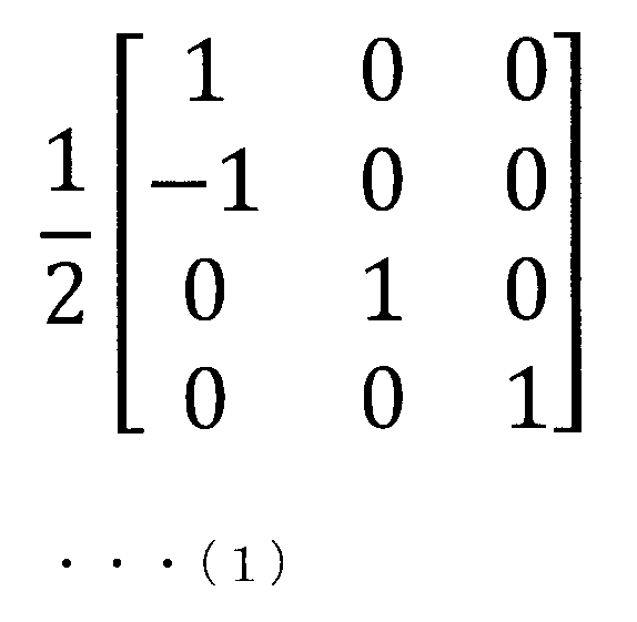
を選択し、プリコーディング行列決定部133の出力として、プリコーディング部115に入力する。
図7は、本発明の第1の実施形態に係る、図4のプリコーディング行列決定部133内の処理を説明するフローチャートである。初めに端末装置1-2は、端末装置1-2自身が持つ送信アンテナ数を把握する(ステップS1)。次に端末装置1-2は、送信アンテナ数に応じて、使用するコードブックを限定する(ステップS3)。この段階でコードブックは、OFDM用とDFT-S-OFDM用の2つに絞られる。次に、端末装置1-2は、基地局装置3から通知される次回の伝送で用いる伝送方式がOFDMであるかどうかを判断する(ステップS5)。伝送方式がOFDMである場合(ステップS5:YES)、端末装置1-2は、OFDM用のコードブックを選択する(ステップS7)。伝送方式がOFDMでない場合(ステップS5:NO)、端末装置1-2は、DFT-S-OFDM用のコードブックを選択する(ステップS9)。最後に、端末装置1-2は、選択したコードブックと、基地局装置3から通知されるPMIによって、次回の伝送に用いるプリコーディング行列を決定し(ステップS11)、決定したプリコーディング行列によって次回の伝送を行なう。
図8は、本発明の第1の実施形態に係る基地局装置3の構成を示す概略ブロック図である。基地局装置3は、受信アンテナ301-1~301-Nr(以下、受信アンテナ301-1~301-Nrを合わせて、受信アンテナ301とも表す)、参照信号分離部303-1~303-Nr(以下、参照信号分離部303-1~303-Nrを合わせて、参照信号分離部303とも表す)、OFDM信号受信部305-1~305-Nr(以下、OFDM信号受信部305-1~305-Nrを合わせて、OFDM信号受信部305とも表す)、スペクトルデマッピング部307-1~307-Nr、MIMO分離部309、切替部311-1~311-L(以下、切替部311-1~311-Lを合わせて、切替部311とも表す)、IDFT部313-1~313-L(以下、IDFT部313-1~313-Lを合わせて、IDFT部313とも表す)、復調部315-1~315-L(以下、復調部315-1~315-Lを合わせて、復調部315とも表す)、復号部317-1~317-L、P/S変換部319、チャネル推定部321、変調方式決定部323、割当情報決定部325、伝送方式決定部327、PMI決定部329、制御情報送信部331を含んで構成される。
端末装置1-1、1-2から送信された信号は、無線チャネル(伝搬路)を経由し、図8の基地局装置3の受信アンテナ301-1~301-Nrで受信される。受信アンテナ301-1~301-Nrで受信された信号は、各々の受信アンテナに接続された参照信号分離部303に入力される。参照信号分離部303では受信された信号を、データ信号と参照信号に分離し、データ信号はOFDM信号受信部305に入力し、参照信号はチャネル推定部321に入力する。チャネル推定部321では、入力された受信参照信号を用いて送信アンテナ121と受信アンテナ301の間のチャネルを推定する。得られたチャネル推定値は、MIMO分離部309、割当情報決定部325、PMI決定部329および変調方式決定部323に入力される。
変調方式決定部323では、入力されたチャネル推定値によって、次の伝送に用いる変調方式を決定し、決定した変調方式を制御情報送信部331に入力する。また決定した変調方式は変調方式決定部323内に保存しておき、端末が送信した信号を復調するため、復調部315-1~315-Lに入力する。また割当情報決定部325では、入力されたチャネル推定値によって、次の伝送にどの端末装置1-2が、どの周波数を用いるかという情報(割当情報)を決定し、PMI決定部329および制御情報送信部331に入力する。また決定した割当情報は、割当情報決定部325内に保存しておき、端末が送信した信号をスペクトルデマッピングするため、スペクトルデマッピング部307-1~307-Nrに入力する。
一方、受信データ信号は、参照信号分離部303からOFDM信号受信部305-1~305-Nrにそれぞれ入力される。図9は本発明の第1の実施形態に係るOFDM信号受信部305の構成を示す概略ブロック図である。OFDM信号受信部305-1~305-Nrの各々は、入力された信号をアナログ処理部401に入力し、搬送波周波数からベースバンドへのダウンコンバージョン、アナログフィルタリング等を行なう。アナログ処理部401の出力は、A/D変換部403に入力され、A/D(アナログ-ディジタル)変換が行なわれる。その後、CP除去部405にて端末装置1-1、1-2により付加されたCPの除去が行なわれ、さらにFFT部407にて高速フーリエ変換(Fast Fourier Transform、FFT)が行なわれ、該変換により生成された周波数領域信号は、各々に接続された図8のスペクトルデマッピング部307-1~307-Nrに出力される。
スペクトルデマッピング部307-1~307-Nrは、割当情報決定部325から入力される割当情報に基づいて、通信に用いられた周波数帯域の周波数領域信号を抽出する。各スペクトルデマッピング部307-1~307-Nrが抽出した周波数領域信号は、MIMO分離部309に入力される。
MIMO分離部309は、スペクトルデマッピング部307-1~307-Nrからの入力と、チャネル推定部321からの入力を用いて空間的に多重されている信号を、L個のレイヤに分離する。分離方法は、空間フィルタリング(ZF(Zero Forcing)、MMSE(Minimum Mean Square Error)等)、SIC(Successive Interference Cancellation)、V-BLAST(Vertical Bell Laboratories layered Space Time)、MLD(Maximum Likelihood Detection)等どのような方法であってもよい。
分離された各レイヤの周波数領域信号は、切替部311-1~311-Lに入力される。各々の切替部311-1~311-Lは、伝送方式決定部327から入力される伝送方式に関する情報によって出力先を変更する。具体的には、伝送方式決定部327から切替部311に入力される情報がSC-FDMA(あるいはClustered DFT-S-OFDM)である場合、切替部311は入力された値をIDFT部313に入力する。一方、伝送方式決定部327から切替部311に入力される情報がOFDMである場合、切替部311は入力された値を復調部315に入力する。
IDFT部313-1~313-Lの各々は、入力された周波数領域信号に対して、逆離散フーリエ変換を施し、時間領域信号に変換する。得られた時間領域信号を、復調部315-1~315-Lに入力する。復調部315では、IDFT部313あるいは切替部311から入力された受信シンボルをビット列に変換する。復調部315の出力は復号部317に入力され、誤り訂正復号が適用される。その後、P/S変換部319は、復号部317-1~317-Lの出力に対して、パラレル-シリアル変換を行ない、送信データビット系列を得る。
また図8の伝送方式決定部327では、端末の許容最大送信電力や、増幅器に対する電力余力(Power Headroom、PH)等を考慮して、上りリンクで端末装置1-2がSC-FDMA(あるいはClustered DFT-S-OFDM)を使用するか、OFDMを使用するかを決定し、PMI決定部329および制御情報送信部331に入力する。また、以前の上りリンクの伝送に用いた伝送方式も記憶しておき、受信処理に用いるため、切替部311に入力する。
図10は、本発明の第1の実施形態に係るPMI決定部329の構成を示す概略ブロック図である。PMI決定部329の処理について図10を用いて説明を行なう。伝送方式決定部327からの入力はコードブック選択部501に入力される。コードブック選択部501では、伝送方式決定部327からの入力、および送信アンテナ数通知部503が通知する端末装置1-2の送信アンテナ数に応じて、コードブックを選択する。例えば、端末装置1-2の送信アンテナ数が4であり、伝送方式がSC-FDMA(あるいはClustered DFT-S-OFDM)の場合には、送信信号のCMを増加させないコードブックである図5に記載のコードブックを用いる。
一方、端末装置1-2の送信アンテナ数が4であり、伝送方式がOFDMの場合には、送信信号のCMが十分高く、どのようなプリコーディングを行なってもCMは変化しない。そこでOFDMの場合には、図6に記載のコードブックを用いる。このようにコードブック選択部501では、伝送方式がCMの低いSC-FDMA(Clustered DFT-S-OFDM)である場合には、CM維持を前提としたコードブックを選択し、伝送方式がCMの高いOFDMである場合には、CM維持を前提とせず、良好な送信アンテナ利得を得ることができるコードブックを選択する。
コードブック選択部501が選択したコードブックはインデックス選択部505に入力される。インデックス選択部505には、割当情報決定部325から割当情報と、チャネル推定部321からチャネル推定値も入力されており、使用するチャネルに応じてコードブックの中から最適なPMIが選択される。たとえばコードブック選択部501から図5のコードブックが入力された場合には、チャネル推定値や送信すべきデータ量等を考慮し、いずれかのプリコーディング行列が選択され、そのインデックスが決定される。
ただし、図5のコードブックの場合、ランク4のプリコーディング行列は、コードブックインデックス=52のひとつしか定義されていない。これは図5がCMを維持することを優先させたコードブックであるためである。一方、図6のコードブックの場合、ランク4のプリコーディング行列として複数のパターンが定義されている。図6のコードブックは、CMを考慮しない結果、より柔軟なプリコーディングを行なうことができ、より大きな送信アンテナダイバーシチ利得を得ることができる。
インデックス選択部505の出力はPMI決定部329の出力として、図8の制御情報送信部331に入力される。制御情報送信部331では、PMI決定部329から入力されるPMI、伝送方式決定部327から入力される伝送方式に関する情報、変調方式決定部323から入力される変調方式に関する情報、割当情報決定部325から入力されるスペクトル割当に関する情報(割当情報)、さらに図示しない他の制御情報(送信電力制御に関する情報や参照信号の生成に関する情報等)も含めて端末装置1-2に送信する。
図11は、本発明の第1の実施形態に係る、図10のPMI決定部329内の処理を説明するフローチャートである。初めに基地局装置3は、対象とする端末装置1-2が持つ送信アンテナ数を把握する(ステップT1)。送信アンテナ数は通信を行なう前に端末装置1-2から予め通知されているものとする。次に基地局装置3は、送信アンテナ数に応じて、使用するコードブックを限定する(ステップT3)。この段階でコードブックは、OFDM用とDFT-S-OFDM用の2つに絞られる。次に、基地局装置3は、次回の伝送で端末装置1-2が用いる伝送方式を、OFDMとするか、DFT-S-OFDMとするかを判断する(ステップT5)。伝送方式がOFDMである場合(ステップT5:YES)、基地局装置3は、OFDM用のコードブックを選択する(ステップT7)。伝送方式がOFDMでない場合(ステップT5:NO)、基地局装置3は、DFT-S-OFDM用のコードブックを選択する(ステップT9)。最後に、基地局装置3は、チャネル推定値と、割当情報と、選択されたコードブックを用いて、次回の伝送に用いるプリコーディング行列を決定し(ステップT11)、そのプリコーディング行列のインデックスをPMIとする。
図12は、本発明の第1の実施形態に係る端末装置1-2と基地局装置3の処理について説明するシーケンスチャートである。初めに端末装置1-2が、参照信号および制御情報を基地局装置3に送信することで(ステップU1)、基地局装置3は次回のアップリンクの伝送に用いる伝送方式を決定し(ステップU3)、図10のPMI決定部329によってPMIを決定する(ステップU5)。決定された次回のアップリンクの伝送に用いる伝送方式情報およびPMIは、基地局装置3から端末装置1-2に通知される(ステップU7)。端末装置1-2は、伝送方式情報から次回のアップリンクの伝送に用いる伝送方式を認識し(ステップU9)、図4のプリコーディング行列決定部133によって、コードブックの選択(ステップU11)、プリコーディング行列の決定を行なう(ステップU13)。端末装置1-2は、決定したプリコーディング行列をデータに乗算し、データ伝送を行なう(ステップU15)。
このように本実施形態では、送信アンテナ数(アンテナポート数)だけではなく、伝送方式によって、使用するコードブックが選択される。よって、複数の伝送方式が定義された通信システムにおいて、同じPMIが通知されたとしても、使用する伝送方式によって異なるプリコーディングを行なうことができる。この結果、各伝送方式に適したプリコーディングを行なうことができるため、同一のプリコーディングを使用する場合と比較し、カバレッジを維持しつつ、スループットを増加させることができる。また、選択された伝送方式に依存してコードブックが選択されるため、どのコードブックを選択するのかという情報を追加する必要がない。この結果、下りリンク制御情報量を増加させることもない。
[第2の実施形態]
第2の実施形態では、SC-FDMAであるか、またはClusteredであるかに応じて、コードブックを変更する。第1の実施形態では、CMが低い伝送方式はSC-FDMAおよびClustered DFT-S-OFDMであり、CMが高い伝送方式はOFDMであるとして説明を行なった。しかし、Clustered DFT-S-OFDMはSC-FDMAと比較してCMが高くなる伝送方式であるため、Clustered DFT-S-OFDMをCMの高い伝送方式とし、SC-FDMAとClustered DFT-S-OFDMで異なるコードブックを用いることも可能である。第2の実施形態では、SC-FDMAをCMが低い伝送方式とし、Clustered DFT-S-OFDMをCMが高い伝送方式として扱った場合について説明を行なう。
第2の実施形態では、SC-FDMAであるか、またはClusteredであるかに応じて、コードブックを変更する。第1の実施形態では、CMが低い伝送方式はSC-FDMAおよびClustered DFT-S-OFDMであり、CMが高い伝送方式はOFDMであるとして説明を行なった。しかし、Clustered DFT-S-OFDMはSC-FDMAと比較してCMが高くなる伝送方式であるため、Clustered DFT-S-OFDMをCMの高い伝送方式とし、SC-FDMAとClustered DFT-S-OFDMで異なるコードブックを用いることも可能である。第2の実施形態では、SC-FDMAをCMが低い伝送方式とし、Clustered DFT-S-OFDMをCMが高い伝送方式として扱った場合について説明を行なう。
図13は、本発明の第2の実施形態に係る端末装置1の通信機構成を示す概略ブロック図である。第1の実施形態で示した図2の送信機構成とほぼ同じ構成であるため、異なるブロックのみ説明を行なう。まず切替部107-1~107-Lが存在しない。これはSC-FDMA、Clustered DFT-S-OFDM共に、DFT部109によるDFT処理を必要とするためである。なお、SC-FDMAおよびClustered DFT-S-OFDMに加えて、OFDMも伝送方式として存在する場合には、第1の実施形態と同様、切替部107が存在することになる。DFT部109以降は第1の実施形態と同様の処理によってアンテナ部から送信される。
一方、制御信号受信部125が受信した制御情報は、割当情報取得部131とプリコーディング行列決定部601、変調方式取得部127に入力される。割当情報取得部131は、入力された制御情報の中から割当情報(スケジューリング情報)を抽出し、スペクトルマッピング部117-1~117-Ntおよびプリコーディング行列決定部601に入力する。スペクトルマッピング部117-1~117-Ntは、入力された割当情報に基づいて、プリコーディング部115から入力されたスペクトルをシステム帯域内の周波数に配置する。
次にプリコーディング行列決定部601の処理について説明を行なう。図14は、本発明の第2の実施形態に係るプリコーディング行列決定部601の構成を示す概略ブロック図である。割当情報取得部131からの入力はコードブック選択部651に入力される。コードブック選択部651では、送信アンテナ数通知部253から通知される端末装置1の送信アンテナ数(アンテナポート数)によって複数のコードブックが選択され、さらに割当情報取得部131からの入力される割当情報によって、所定のコードブックが選択される。
例えば、割当情報取得部131から入力される割当情報が連続配置、つまり伝送方式がSC-FDMAである場合には、図5のようなCMの維持を優先したコードブックが選択され、割当情報取得部131から入力される割当情報が非連続配置、つまり伝送方式がClustered DFT-S-OFDMである場合には、図6のような良好な送信アンテナ利得を得ることができるコードブックが選択される。選択されたコードブックはプリコーディング行列選択部255に入力される。
なお、Clustered DFT-S-OFDMでは、クラスタ数が多くなるにつれてCMが高くなるという特徴がある。そこで、Clustered DFT-S-OFDMのクラスタ数に応じてコードブックを用意することが考えられる。つまり、伝送方式がSC-FDMA、あるいはクラスタ数が2のClustered DFT-S-OFDMである場合は、CMが増加しないコードブックを用い、クラスタ数が3つ以上である場合には、送信アンテナダイバーシチ利得が高いコードブックを変更することも本発明に含まれる。また上記では用意するコードブックは2つとして説明を行なったが、Clustered DFT-S-OFDMのクラスタ数に応じて3つ以上のコードブックがシステムに用意されていてもよい。
またPMI取得部257では、制御信号受信部125から入力される制御情報の中からPMIを抽出し、プリコーディング行列選択部255に入力する。プリコーディング行列選択部255では、コードブック選択部651から入力されたコードブック中の、PMIに対応するプリコーディング行列を選択し、プリコーディング行列決定部601の出力として、プリコーディング部115に入力する。
図15は、本発明の第2の実施形態に係る、図14のプリコーディング行列決定部601内の処理を説明するフローチャートである。なお、図7と同じ処理については同じ番号を付した。初めに端末装置1は、端末装置1自身が持つ送信アンテナ数を把握する(ステップS1)。次に端末装置1は、送信アンテナ数に応じて、使用するコードブックを限定する(ステップS103)。次に、端末装置1は、周波数配置が連続配置かどうかを判断する(ステップS105)。周波数配置が連続配置である場合(ステップS105:YES)、端末装置1は、SC-FDMA用のコードブックを選択する(ステップS107)。周波数配置が連続配置でない場合(ステップS105:NO)、端末装置1は、Clustered DFT-S-OFDM用のコードブックを選択する(ステップS109)。最後に、端末装置1は、選択したコードブックと、基地局装置3から通知されるPMIによって、次回の伝送に用いるプリコーディング行列を決定し(ステップS11)、決定したプリコーディング行列によって次回の伝送を行なう。
図16は、本発明の第2の実施形態に係る基地局装置3の受信機構成を示す概略ブロック図である。第1の実施形態で示した図8の構成とほぼ同じ構成であるため、異なるブロックについてのみ説明を行なう。OFDMが伝送方式として存在しないため、端末構成と同様、切替部311-1~311-Lが存在せず、MIMO分離部309の出力は、IDFT部313-1~313-Lに入力される。
また、PMI決定部701の構成が第1の実施形態とは異なるため図17を用いて説明を行なう。図17は、本発明の第2の実施形態に係るPMI決定部701の構成を示す概略ブロック図である。割当情報決定部325から入力される割当情報は、コードブック選択部801およびインデックス選択部505に入力される。コードブック選択部801では、複数のコードブックの中から、送信アンテナ数通知部503から通知される端末装置1の送信アンテナ数(アンテナポート数)によって複数のコードブックが選択され、さらに割当情報決定部325から入力される割当情報によって、所定のコードブックが選択される。
例えば、割当情報が連続配置(つまり伝送方式がSC-FDMA)であれば、図5のようなCM維持を優先したプリコーディング行列から構成されるコードブックを選択し、割当情報が非連続配置(つまり伝送方式がClustered DFT-S-OFDM)であれば、図6のような送信アンテナダイバーシチ利得を優先したプリコーディング行列から構成されるコードブックを選択する。選択されたコードブックは、インデックス選択部505に入力される。インデックス選択部505は、チャネル推定部321から入力されるチャネル推定値と、コードブック選択部801から入力されるコードブック、および割当情報決定部325から入力される割当情報を用い、コードブックの中のどのプリコーディング行列を上りリンクの伝送に用いるかを決定し、そのインデックスを制御情報送信部331に入力する。
図18は、本発明の第2の実施形態に係る、図17のPMI決定部701内の処理を説明するフローチャートである。なお、図11と同じ処理については同じ番号を付した。初めに基地局装置3は、対象とする端末装置1が持つ送信アンテナ数を把握する(ステップT1)。送信アンテナ数は通信を行なう前に端末装置1から予め通知されているものとする。次に基地局装置3は、送信アンテナ数に応じて、使用するコードブックを限定する(ステップT103)。次に、基地局装置3は、周波数配置が連続配置かどうかを判断する(ステップT105)。周波数配置が連続配置である場合(ステップT105:YES)、基地局装置3は、SC-FDMA用のコードブックを選択する(ステップT107)。周波数配置が連続配置でない場合(ステップT105:NO)、基地局装置3は、Clustered DFT-S-OFDM用のコードブックを選択する(ステップT109)。最後に、基地局装置3は、チャネル推定値と、割当情報と、選択されたコードブックを用いて、次回の伝送に用いるプリコーディング行列を決定し(ステップT11)、そのプリコーディング行列のインデックスをPMIとする。
図19は、本発明の第2の実施形態に係る端末装置1と基地局装置3の処理について説明するシーケンスチャートである。初めに端末装置1が、参照信号および制御情報を基地局装置3に送信することで(ステップU1)、基地局装置3は次回のアップリンクの伝送に用いる割当RBを決定し(ステップU103)、図17のPMI決定部701によってPMIを決定する(ステップU5)。決定された次回のアップリンクの伝送に用いる割当RB(周波数)およびPMIは、基地局装置3から端末装置1に通知される(ステップU107)。端末装置1は、伝送方式情報から次回のアップリンクの伝送に用いる割当RBを認識し(ステップU109)、図14のプリコーディング行列決定部601によって、コードブックの選択(ステップU11)、プリコーディング行列の決定を行なう(ステップU13)。端末装置1は、決定したプリコーディング行列をデータに乗算し、データ伝送を行なう(ステップU15)。
なおOFDMと異なり、一般にClustered DFT-S-OFDMはプリコーディングによってCMが増加する。図6では、コードブック内の所定のランクの伝送を行なうための複数プリコーディング行列は、どの行列も統計的にはCMの増加量は一定であるが、CMの増加量に差があるプリコーディング行列をコードブック化してもよい。例えば図6において、ランク2のプリコーディングには、インデックス4~15の12個が用意されており、すべてCMP型ではないが、12個中4つをCMP型に置き換えたものをコードブックとして用い、8つはCMが増加するようなコードブックを用いる。このようなコードブックを用意すれば、例えば端末装置1が基地局装置3に通知するPHの大きさによって、基地局装置3は、端末装置1の送信信号のCMを上げすぎないプリコーディング行列を選択することができる。
このように本実施形態のPMI決定部701では、スペクトルの割当が連続的である場合はCMを維持するプリコーディングを行なうように動作し、スペクトルの割当が非連続的である場合は、プリコーディングによらず、ある程度CMが高くなっているため、CMの増加を許容し、送信アンテナダイバーシチ利得が大きくなるプリコーディングを行なうように動作する。この結果、CMを維持するプリコーディング行列のみから構成されるコードブックを用いる場合と比較して、カバレッジを維持しつつ、CMの劣化が重要ではない端末装置1の伝送特性を改善できるため、セルスループットを増加させることができる。
また第2の実施形態では、送信信号がSC-FDMAであるか、Clustered DFT-S-OFDMであるかによってプリコーディングのコードブックの選択を行なったが、SC-FDMAはCMを維持するプリコーディング行列のみから構成されるコードブックを用い、Clustered DFT-S-OFDMについては、そのスペクトルマッピングの状態によって、CMを維持するプリコーディング行列から構成されるコードブックと、送信アンテナダイバーシチ利得を優先したプリコーディング行列から構成されるコードブックを選択する構成としてもよい。
図20A、図20Bおよび図21A、図21Bは、クラスタが配置されたシステム帯域の模式図である。例えば、2クラスタから構成されるClustered DFT-S-OFDMにおいて、図20Aのように各クラスタが離れて配置された場合、スペクトルマスクに対するシステム帯域外への輻射の影響が大きくなってしまうため、電力を抑えて送信する必要がある。この結果、平均送信電力を下げて送信を行なうことになるため、ピーク電力を増加させても、増幅器の線形領域内で増幅を行なうことができる。したがって、送信アンテナダイバーシチ利得を優先したプリコーディング行列から構成されるコードブックを選択する。一方、図20Bのように、各クラスタが近くに配置された場合、スペクトルマスクに対するシステム帯域外への輻射の影響を図20Aの場合より抑えることができるため、電力を抑えて送信する必要はない。この場合、平均送信電力を上げて送信を行なうことになるため、ピーク電力を増加させると増幅器の線形領域を超えてしまう。したがって、CMを維持するプリコーディング行列から構成されるコードブックを選択する。
このように、クラスタ間の距離の値が、所定の値より大きい場合、送信アンテナダイバーシチ利得を優先したプリコーディング行列から構成されるコードブックを選択し、クラスタ間の距離の値が、所定の値より小さい場合、CMを維持するプリコーディング行列から構成されるコードブックを選択することも本発明に含まれる。また、図21Aのように、システム帯域に対して使用帯域が広い場合、クラスタ間の距離が狭くなる確率が高く、図21Bのようにシステム帯域に対して使用帯域が狭い場合、クラスタ間の距離が広くなる確率が高い。そこでシステム帯域に対する使用帯域幅を算出し、その比によって、使用するコードブックを選択する構成としてもよい。
[第3の実施形態]
第3の実施形態では、変調方式によってコードブックを変更する。第1および第2の実施形態では、伝送方式によってCMが異なるため、伝送方式によってプリコーディング方法を変更する場合について説明した。ここでCMが変化するのは、伝送方式が変わった時だけではない。
第3の実施形態では、変調方式によってコードブックを変更する。第1および第2の実施形態では、伝送方式によってCMが異なるため、伝送方式によってプリコーディング方法を変更する場合について説明した。ここでCMが変化するのは、伝送方式が変わった時だけではない。
例えば、LTE-Aではキャリアアグリゲーションと呼ばれる、同時に複数のLTEコンポーネントキャリアを使用するN×DFT-S-OFDMによる伝送が仕様化されているが、複数のコンポーネントキャリアを1つの増幅器で増幅する場合にもCMが増加してしまう。また、LTE Rel-8では、データを送信するPUSCH(Physical Uplink Shared CHannel)と制御情報を送信するPUCCH(Physical Uplink Control CHannel)は同時に送信することはできなかったが、LTE Rel-10では、PUSCHとPUCCHを同時に送信することが仕様化されている。この時2つの信号を1つのアンテナから同時に送信するため、送信信号はマルチキャリア信号となる。この結果、送信信号のCMは増加する。キャリアアグリゲーションや、PUSCHとPUCCHの同時送信の他にも、用いる変調方式によってCMは変化する。そこで本実施形態では他のCMが変化する場合として、変調方式について説明を行なう。
図22は、本発明の第3の実施形態に係る端末装置1の送信機構成を示す概略ブロック図である。第2の実施形態で示した図13の送信機構成とほぼ同じ構成であるため、異なるブロックのみ説明を行なう。異なる点はプリコーディング行列決定部901への入力および内部での処理であり、その点についてのみ説明を行なう。第2の実施形態ではスペクトルの割当(SC-FDMAであるかClustered DFT-S-OFDMであるか)によって選択するコードブックが異なったため、割当情報取得部131の出力がプリコーディング行列決定部901に入力されていた。一方本実施形態では、変調方式によって選択するコードブックを変更するため、変調方式取得部127から変調方式に関する情報がプリコーディング行列決定部901に入力される。
次にプリコーディング行列決定部901の内部処理の一例について図23を用いて説明を行なう。図23は、本発明の第3の実施形態に係るプリコーディング行列決定部901の構成を示す概略ブロック図である。変調方式取得部127からの入力はコードブック選択部1001に入力される。コードブック選択部1001では、複数のコードブックの中から、送信アンテナ数通知部253から通知される端末装置1の送信アンテナ数(アンテナポート数)によって複数のコードブックが選択され、さらに変調方式取得部127からの入力される変調方式によって、所定のコードブックが選択される。
例えば変調方式取得部127から入力される変調方式がBPSKやQPSK、あるいは8PSKや16PSKのようなCMの低い方式である場合には、図5のようなCMの維持を優先したコードブックが選択され、変調方式取得部127から入力される変調方式が16QAMや、16QAMよりさらにCMが高い64QAM、さらには256QAMのようなCMの高い方式である場合には、図6のような良好な送信アンテナ利得を得ることができるコードブックが選択される。選択されたコードブックはプリコーディング行列選択部255に入力される。なお、上記では16QAMをCMが高い変調方式とみなしたが、CMの高低は相対的なものであるため、64QAM以上をCMの高い変調方式とすることも当然本発明に含まれる。
また制御信号受信部125からの入力はPMI取得部257に入力され、制御情報の中からPMIを抽出し、得られたPMIをプリコーディング行列選択部255に入力する。プリコーディング行列選択部255では、コードブック選択部1001から入力されたコードブック中の、PMIに対応するプリコーディング行列を選択し、プリコーディング行列決定部901の出力として、プリコーディング部115に入力する。
図24は、本発明の第3の実施形態に係る、図23のプリコーディング行列決定部901内の処理を説明するフローチャートである。なお、図7、図15と同じ処理については同じ番号を付した。初めに端末装置1は、端末装置1自身が持つ送信アンテナ数を把握する(ステップS1)。次に端末装置1は、送信アンテナ数に応じて、使用するコードブックを限定する(ステップS103)。次に、端末装置1は、変調方式がPSKかどうかを判断する(ステップS205)。変調方式がPSKである場合(ステップS205:YES)、端末装置1は、CM維持のコードブックを選択する(ステップS207)。変調方式がPSKでない場合(ステップS205:NO)、端末装置1は、ダイバーシチ利得優先のコードブックを選択する(ステップS209)。最後に、端末装置1は選択したコードブックと、基地局装置3から通知されるPMIによって、次回の伝送に用いるプリコーディング行列を決定し(ステップS11)、決定したプリコーディング行列によって次回の伝送を行なう。
次に本実施形態における基地局装置3の受信機構成の一例を図25に示す。図25は、本発明の第3の実施形態に係る基地局装置3の受信機構成を示す概略ブロック図である。第2の実施形態で示した図16の構成とほぼ同じ構成であるが、PMI決定部1101への入力、および内部処理が異なる。PMI決定部1101は、チャネル推定部321から入力されるチャネル推定値と割当情報決定部325から入力される割当情報に加えて、変調方式決定部323からも入力される。PMI決定部1101の内部処理について図26を用いて説明を行なう。図26は、本発明の第3の実施形態に係るPMI決定部1101の構成を示す概略ブロック図である。変調方式決定部323から入力される情報はコードブック選択部1201に入力される。
コードブック選択部1201では、複数のコードブックの中から、送信アンテナ数通知部503から通知される端末装置1の送信アンテナ数(アンテナポート数)によって複数のコードブックが選択され、さらに変調方式決定部323から入力される変調方式によって、所定のコードブックが選択される。つまり、変調方式決定部323から入力される変調方式がCMの低い方式(例えばBPSKやQPSK)であれば、図5のようなCM維持を優先したプリコーディング行列から構成されるコードブックを選択し、変調方式がCMの高い方式(例えば64QAMや256QAM)であれば、図6のような良好な送信アンテナ利得を得ることができるコードブックを選択する。
選択されたコードブックはインデックス選択部505に入力される。インデックス選択部505は、チャネル推定部321から入力されるチャネル推定値と、コードブック選択部1201から入力されるコードブック、および割当情報決定部325から入力される割当情報を用い、コードブックの中のどのプリコーディング行列を上りリンクの伝送に用いるかを決定し、そのインデックスを制御情報送信部331に入力する。このように本実施形態のPMI決定部1101では、CMの低い変調方式を用いる場合には、CMを維持するプリコーディングを行なうように動作し、CMの高い変調方式を用いる場合は、プリコーディングによらず、ある程度CMが高くなっているため、CMの増加を許容し、送信アンテナダイバーシチ利得が大きくなるプリコーディングを行なうように動作する。
図27は、本発明の第3の実施形態に係る、図26のPMI決定部1101内の処理を説明するフローチャートである。なお、図11、図18と同じ処理については同じ番号を付した。初めに基地局装置3は、対象とする端末装置1が持つ送信アンテナ数を把握する(ステップT1)。送信アンテナ数は通信を行なう前に端末装置1から予め通知されているものとする。次に送信アンテナ数に応じて、使用するコードブックを限定する(ステップT103)。次に、基地局装置3は、変調方式がPSKかどうかを判断する(ステップT205)。変調方式がPSKである場合(ステップT205:YES)、基地局装置3は、CM維持のコードブックを選択する(ステップT207)。変調方式がPSKでない場合(ステップT205:NO)、基地局装置3は、ダイバーシチ利得優先のコードブックを選択する(ステップT209)。最後に、基地局装置3は、チャネル推定値と、割当情報と、選択されたコードブックを用いて、次回の伝送に用いるプリコーディング行列を決定し(ステップT11)、そのプリコーディング行列のインデックスをPMIとする。
図28は、本発明の第3の実施形態に係る端末装置1と基地局装置3の処理について説明するシーケンスチャートである。初めに端末装置1が、参照信号および制御情報を基地局装置3に送信することで(ステップU1)、基地局装置3は次回のアップリンクの伝送に用いるMCSを決定し(ステップU203)、図26のPMI決定部1101によってPMIを決定する(ステップU5)。決定された次回のアップリンクの伝送に用いるMCS情報およびPMIは、基地局装置3から端末装置1に通知される(ステップU207)。端末装置1は、MCS情報から次回のアップリンクの伝送に用いるMCSを認識し(ステップU209)、図22のプリコーディング行列決定部901によって、コードブックの選択(ステップU11)、プリコーディング行列の決定を行なう(ステップU13)。端末装置1は、決定したプリコーディング行列をデータに乗算し、データ伝送を行なう(ステップU15)。
本実施形態の効果について説明を行なう。セル中央の端末装置1ほど高い電力で受信されるように送信電力制御(Transmit Power Control、TPC)を行なうフラクショナルTPCでは、セルエッジの端末装置1の信号は低い電力で受信されるため、低多値数の変調方式、つまりQPSK等を伝送に用いることが多い。この場合、本実施形態のPMI決定法では、CMを維持したプリコーディングを行なうため、伝送特性を劣化させることはない。
一方、セル中央の端末装置1の信号は高い電力で受信されるため、高次の多値数の変調方式、つまり64QAM等を伝送に用いることが多い。この場合、本実施形態のPMI決定法では、送信アンテナダイバーシチ利得が大きくなるプリコーディング行列を選択するため、全端末装置1にCMを維持したプリコーディングを行なう場合と比較して、伝送特性を改善することができる。つまり本実施形態は、特にフラクショナルTPCにおいて効果が高い。
上記の各実施形態は組み合わせて実現することも可能である。例えば変調多値数が高く、かつ伝送方式がClustered DFT-S-OFDMの場合に、CMを維持しないプリコーディングを行なったり、例えば変調多値数が高い、または伝送方式がOFDMあるいはClustered DFT-S-OFDMの場合に、CMを維持しないプリコーディングを行なったりすることも本発明に含まれる。
本発明に関わる端末装置1および基地局装置3で動作するプログラムは、本発明に関わる上記実施形態の機能を実現するように、CPU等を制御するプログラム(コンピュータを機能させるプログラム)である。そして、これら装置で取り扱われる情報は、その処理時に一時的にRAMに蓄積され、その後、各種ROMやHDDに格納され、必要に応じてCPUによって読み出し、修正・書き込みが行なわれる。プログラムを格納する記録媒体としては、半導体媒体(例えば、ROM、不揮発性メモリカード等)、光記録媒体(例えば、DVD、MO、MD、CD、BD等)、磁気記録媒体(例えば、磁気テープ、フレキシブルディスク等)等のいずれであってもよい。また、ロードしたプログラムを実行することにより、上述した実施形態の機能が実現されるだけでなく、そのプログラムの指示に基づき、オペレーティングシステムあるいは他のアプリケーションプログラム等と共同して処理することにより、本発明の機能が実現される場合もある。
また市場に流通させる場合には、可搬型の記録媒体にプログラムを格納して流通させたり、インターネット等のネットワークを介して接続されたサーバコンピュータに転送したりすることができる。この場合、サーバコンピュータの記憶装置も本発明に含まれる。また、上述した実施形態における端末装置1および基地局装置3の一部、または全部を典型的には、集積回路であるLSIとして実現してもよい。端末装置1および基地局装置3の各機能ブロックは個別にチップ化してもよいし、一部、または全部を集積してチップ化してもよい。また、集積回路化の手法はLSIに限らず、専用回路、または汎用プロセッサで実現しても良い。ハイブリッド、モノリシックのいずれでも良い。一部は、ハードウェアにより、一部はソフトウェアにより機能を実現させても良い。また、半導体技術の進歩により、LSIに代替する集積回路化等の技術が出現した場合、当該技術による集積回路を用いることも可能である。
以上、この発明の実施形態を、図面を参照して詳述してきたが、具体的な構成はこの実施形態に限られるものではなく、この発明の要旨を逸脱しない範囲の設計等も特許請求の範囲に含まれる。本発明は、携帯電話装置を端末装置1とする移動通信システムに用いることができる。
1、1-1、1-2 端末装置
3 基地局装置
101 S/P変換部
103、103-1~103-L 符号化部
105、105-1~105-L 変調部
107、107-1~107-L 切替部
109、109-1~109-L DFT部
111、111-1~111-L 参照信号多重部
113 参照信号生成部
115 プリコーディング部
117、117-1~117-Nt スペクトルマッピング部
119、119-1~119-Nt OFDM信号生成部
121、121-1~121-Nt 送信アンテナ
123 受信アンテナ
125 制御信号受信部
127 変調方式取得部
129 伝送方式識別部
131 割当情報取得部
133 プリコーディング行列決定部
201 IFFT部
203 CP挿入部
205 D/A変換部
207 アナログ処理部
251 コードブック選択部
253 送信アンテナ数通知部
255 プリコーディング行列選択部
257 PMI取得部
301、301-1~301-Nr 受信アンテナ
303、303-1~303-Nr 参照信号分離部
305、305-1~305-Nr OFDM信号受信部
307、307-1~307-Nr スペクトルデマッピング部
309 MIMO分離部
311、311-1~311-L 切替部
313、313-1~313-L IDFT部
315、315-1~315-L 復調部
317、317-1~317-L 復号部
319 P/S変換部
321 チャネル推定部
323 変調方式決定部
325 割当情報決定部
327 伝送方式決定部
329 PMI決定部
331 制御情報送信部
401 アナログ処理部
403 A/D変換部
405 CP除去部
407 FFT部
501 コードブック選択部
503 送信アンテナ数通知部
505 インデックス選択部
601 プリコーディング行列決定部
651 コードブック選択部
701 PMI決定部
801 コードブック選択部
901 プリコーディング行列決定部
1001 コードブック選択部
1101 PMI決定部
1201 コードブック選択部
3 基地局装置
101 S/P変換部
103、103-1~103-L 符号化部
105、105-1~105-L 変調部
107、107-1~107-L 切替部
109、109-1~109-L DFT部
111、111-1~111-L 参照信号多重部
113 参照信号生成部
115 プリコーディング部
117、117-1~117-Nt スペクトルマッピング部
119、119-1~119-Nt OFDM信号生成部
121、121-1~121-Nt 送信アンテナ
123 受信アンテナ
125 制御信号受信部
127 変調方式取得部
129 伝送方式識別部
131 割当情報取得部
133 プリコーディング行列決定部
201 IFFT部
203 CP挿入部
205 D/A変換部
207 アナログ処理部
251 コードブック選択部
253 送信アンテナ数通知部
255 プリコーディング行列選択部
257 PMI取得部
301、301-1~301-Nr 受信アンテナ
303、303-1~303-Nr 参照信号分離部
305、305-1~305-Nr OFDM信号受信部
307、307-1~307-Nr スペクトルデマッピング部
309 MIMO分離部
311、311-1~311-L 切替部
313、313-1~313-L IDFT部
315、315-1~315-L 復調部
317、317-1~317-L 復号部
319 P/S変換部
321 チャネル推定部
323 変調方式決定部
325 割当情報決定部
327 伝送方式決定部
329 PMI決定部
331 制御情報送信部
401 アナログ処理部
403 A/D変換部
405 CP除去部
407 FFT部
501 コードブック選択部
503 送信アンテナ数通知部
505 インデックス選択部
601 プリコーディング行列決定部
651 コードブック選択部
701 PMI決定部
801 コードブック選択部
901 プリコーディング行列決定部
1001 コードブック選択部
1101 PMI決定部
1201 コードブック選択部
Claims (9)
- 複数の送信アンテナを備え、送信信号に対してプリコーディングを行なう端末装置であって、
前記送信アンテナの数および前記送信アンテナの数以外の送信パラメータに基づいて、複数のプリコーディング行列を含む複数のコードブックからいずれか一つのコードブックを選択するコードブック選択部と、
PMI(Precoding Matrix Indicator)に基づいて、前記選択したコードブックからいずれか一つのプリコーディング行列を選択するプリコーディング行列選択部と、を備えることを特徴とする端末装置。 - 前記送信パラメータは、送信信号のCM(Cubic Metric)の大きさであることを特徴とする請求項1記載の端末装置。
- 前記送信パラメータは、伝送方式を示す情報であることを特徴とする請求項1記載の端末装置。
- 前記送信パラメータは、スペクトルの割り当てパターンを示す情報であることを特徴とする請求項1記載の端末装置。
- 前記送信パラメータは、変調方式を示す情報であることを特徴とする請求項1記載の端末装置。
- 前記コードブック選択部は、送信信号のCM(Cubic Metric)を維持する複数のプリコーディング行列を含むコードブックまたは良好な送信アンテナ利得が得られる複数のプリコーディング行列を含むコードブックのいずれか一方を選択することを特徴とする請求項1記載の端末装置。
- プリコーディングを行なった信号を複数の送信アンテナを用いて送信する端末装置と無線通信を行なう基地局装置であって、
前記端末装置の送信アンテナの数および前記送信アンテナの数以外の送信パラメータに基づいて、複数のプリコーディング行列を含む複数のコードブックからいずれか一つのコードブックを選択するコードブック選択部と、
前記選択したコードブックからいずれか一つのプリコーディング行列を選択し、前記選択したプリコーディング行列を示すインデックスを選択するインデックス選択部と、を備え、
前記選択したインデックスを示す情報を、前記端末装置に送信することを特徴とする基地局装置。 - 複数の送信アンテナを備え、送信信号に対してプリコーディングを行なう端末装置を制御するプログラムであって、
前記送信アンテナの数および前記送信アンテナの数以外の送信パラメータに基づいて、複数のプリコーディング行列を含む複数のコードブックからいずれか一つのコードブックを選択する処理と、
PMI(Precoding Matrix Indicator)に基づいて、前記選択したコードブックからいずれか一つのプリコーディング行列を選択する処理と、を含む一連の処理を、コンピュータに実行させることを特徴とするプログラム。 - 複数の送信アンテナを備えた端末装置に実装されることにより、前記端末装置に複数の機能を発揮させる集積回路であって、
前記送信アンテナの数および前記送信アンテナの数以外の送信パラメータに基づいて、複数のプリコーディング行列を含む複数のコードブックからいずれか一つのコードブックを選択する機能と、
PMI(Precoding Matrix Indicator)に基づいて、前記選択したコードブックからいずれか一つのプリコーディング行列を選択する機能と、
前記選択したプリコーディング行列を用いて、送信信号に対してプリコーディングを行なう機能と、の一連の機能を、前記端末装置に発揮させることを特徴とする集積回路。
Priority Applications (1)
| Application Number | Priority Date | Filing Date | Title |
|---|---|---|---|
| US14/236,990 US20140205038A1 (en) | 2011-08-10 | 2012-07-26 | Terminal device, base station device, program, and integrated circuit |
Applications Claiming Priority (2)
| Application Number | Priority Date | Filing Date | Title |
|---|---|---|---|
| JP2011-174473 | 2011-08-10 | ||
| JP2011174473A JP2013038666A (ja) | 2011-08-10 | 2011-08-10 | 端末装置、基地局装置、プログラムおよび集積回路 |
Publications (1)
| Publication Number | Publication Date |
|---|---|
| WO2013021827A1 true WO2013021827A1 (ja) | 2013-02-14 |
Family
ID=47668342
Family Applications (1)
| Application Number | Title | Priority Date | Filing Date |
|---|---|---|---|
| PCT/JP2012/068958 Ceased WO2013021827A1 (ja) | 2011-08-10 | 2012-07-26 | 端末装置、基地局装置、プログラムおよび集積回路 |
Country Status (3)
| Country | Link |
|---|---|
| US (1) | US20140205038A1 (ja) |
| JP (1) | JP2013038666A (ja) |
| WO (1) | WO2013021827A1 (ja) |
Families Citing this family (14)
| Publication number | Priority date | Publication date | Assignee | Title |
|---|---|---|---|---|
| US9240956B2 (en) * | 2012-03-11 | 2016-01-19 | Broadcom Corporation | Communication system using orbital angular momentum |
| WO2016203429A1 (en) * | 2015-06-18 | 2016-12-22 | Telefonaktiebolaget L M Ericsson (Publ) | Systems and methods for adapting a codebook for use with multiple antenna configurations |
| EP3419190A4 (en) * | 2016-03-10 | 2019-01-02 | Huawei Technologies Co., Ltd. | Transmission diversity method, device and system |
| CN115189735B (zh) | 2016-06-30 | 2024-03-26 | 松下电器(美国)知识产权公司 | 发送方法以及发送设备 |
| CN107733592B (zh) | 2016-08-10 | 2020-11-27 | 华为技术有限公司 | 传输方案指示方法、数据传输方法、装置及系统 |
| EP3384610B1 (en) * | 2017-02-10 | 2020-05-06 | Telefonaktiebolaget LM Ericsson (publ) | Methods for selecting a codebook |
| CA3056153C (en) * | 2017-03-14 | 2022-12-06 | Guangdong Oppo Mobile Telecommunications Corp., Ltd. | Uplink signal transmission method and related device |
| CN111034062A (zh) * | 2017-06-23 | 2020-04-17 | 株式会社Ntt都科摩 | 用户终端以及无线通信方法 |
| CN109391301B (zh) * | 2017-08-11 | 2021-12-14 | 大唐移动通信设备有限公司 | 一种上行传输码本确定方法及设备 |
| CN109803419B (zh) * | 2017-11-17 | 2024-11-12 | 华为技术有限公司 | 一种通信方法、终端及基站 |
| CN111886809B (zh) * | 2018-04-04 | 2022-08-09 | 华为技术有限公司 | 上行天线的选择方法和装置 |
| JP6657371B2 (ja) * | 2018-12-28 | 2020-03-04 | 三菱電機株式会社 | 送信装置、送信方法、制御回路およびプログラム |
| JP6972196B2 (ja) * | 2018-12-28 | 2021-11-24 | 三菱電機株式会社 | 送信装置、プログラムおよび送信方法 |
| US11445500B2 (en) * | 2020-05-06 | 2022-09-13 | Cisco Technology, Inc. | Time-sensitive networking in high density networks |
Citations (5)
| Publication number | Priority date | Publication date | Assignee | Title |
|---|---|---|---|---|
| WO2009153978A1 (ja) * | 2008-06-17 | 2009-12-23 | パナソニック株式会社 | 無線送信装置及び無線送信方法 |
| WO2010002325A1 (en) * | 2008-07-01 | 2010-01-07 | Telefonaktiebolaget L M Ericsson (Publ) | Methods and apparatus using precoding matrices in a mimo telecommunications system |
| WO2010038474A1 (ja) * | 2008-10-03 | 2010-04-08 | パナソニック株式会社 | 無線送信装置、移動局装置及びプリコーディング方法 |
| WO2010093179A2 (en) * | 2009-02-13 | 2010-08-19 | Lg Electronics Inc. | Uplink precoding method in 4-tx system |
| WO2010093226A2 (ko) * | 2009-02-13 | 2010-08-19 | 엘지전자주식회사 | 다중안테나 시스템에서 데이터 전송방법 및 장치 |
Family Cites Families (8)
| Publication number | Priority date | Publication date | Assignee | Title |
|---|---|---|---|---|
| CN101166052B (zh) * | 2006-10-19 | 2012-05-23 | 株式会社Ntt都科摩 | 一种多输入多输出系统的预编码方法及使用该方法的设备 |
| US9001802B2 (en) * | 2008-08-11 | 2015-04-07 | Lg Electronics Inc. | Method and apparatus for transmitting uplink signals using multi-antenna |
| US8451932B2 (en) * | 2009-02-23 | 2013-05-28 | Texas Instruments Incorporated | Precoding codebook design for single user MIMO |
| US8761086B2 (en) * | 2009-11-02 | 2014-06-24 | Qualcomm Incorporated | Method and apparatus for hierarchical codebook design in wireless communication |
| KR101555820B1 (ko) * | 2009-12-02 | 2015-10-06 | 삼성전자주식회사 | 접속망의 클래스에 따라 비대칭적인 피드백 기법을 사용하는 계층 셀 통신 시스템 |
| WO2011083431A2 (en) * | 2010-01-11 | 2011-07-14 | Koninklijke Philips Electronics N.V. | A method for configuring a transmission mode in a wireless network |
| US8891652B2 (en) * | 2010-06-24 | 2014-11-18 | Qualcomm Incorporated | Structured MIMO codebook |
| US20120328031A1 (en) * | 2011-06-24 | 2012-12-27 | Nokia Siemens Networks Oy | Codebooks for Mobile Communications |
-
2011
- 2011-08-10 JP JP2011174473A patent/JP2013038666A/ja active Pending
-
2012
- 2012-07-26 WO PCT/JP2012/068958 patent/WO2013021827A1/ja not_active Ceased
- 2012-07-26 US US14/236,990 patent/US20140205038A1/en not_active Abandoned
Patent Citations (5)
| Publication number | Priority date | Publication date | Assignee | Title |
|---|---|---|---|---|
| WO2009153978A1 (ja) * | 2008-06-17 | 2009-12-23 | パナソニック株式会社 | 無線送信装置及び無線送信方法 |
| WO2010002325A1 (en) * | 2008-07-01 | 2010-01-07 | Telefonaktiebolaget L M Ericsson (Publ) | Methods and apparatus using precoding matrices in a mimo telecommunications system |
| WO2010038474A1 (ja) * | 2008-10-03 | 2010-04-08 | パナソニック株式会社 | 無線送信装置、移動局装置及びプリコーディング方法 |
| WO2010093179A2 (en) * | 2009-02-13 | 2010-08-19 | Lg Electronics Inc. | Uplink precoding method in 4-tx system |
| WO2010093226A2 (ko) * | 2009-02-13 | 2010-08-19 | 엘지전자주식회사 | 다중안테나 시스템에서 데이터 전송방법 및 장치 |
Non-Patent Citations (1)
| Title |
|---|
| OSAMU NAKAMURA ET AL.: "A study of Frequency Selective Precoding for Clustered DFT-S-OFDM", IEICE TECHNICAL REPORT, vol. 109, no. 341, 10 December 2009 (2009-12-10), pages 49 - 54 * |
Also Published As
| Publication number | Publication date |
|---|---|
| US20140205038A1 (en) | 2014-07-24 |
| JP2013038666A (ja) | 2013-02-21 |
Similar Documents
| Publication | Publication Date | Title |
|---|---|---|
| WO2013021827A1 (ja) | 端末装置、基地局装置、プログラムおよび集積回路 | |
| KR101823485B1 (ko) | 하향링크 신호 전송 방법 및 기지국, 그리고 하향링크 신호 수신 방법 및 사용자기기 | |
| TWI383631B (zh) | 用於無線通信之多載波及單載波多工方案之結合使用之方法、裝置及處理器可讀媒體 | |
| US8699609B2 (en) | Methods and arrangements for peak to average power ratio reduction | |
| JP5356339B2 (ja) | 端末装置、基地局装置、通信システムおよび通信方法 | |
| KR101569215B1 (ko) | 공간 다중화 기법을 이용한 데이터 전송방법 | |
| US8520494B2 (en) | Precoding method for reducing uplink PAPR and apparatus thereof | |
| EP3288203A1 (en) | Terminal device and base station device | |
| EP2807772A1 (en) | Time and frequency synchronization for lte-advanced new carrier type | |
| KR20110081946A (ko) | 다중 안테나 시스템에서 다중 부호어의 전송방법 | |
| KR20130050111A (ko) | 다중 안테나를 위한 제어 채널 검색 방법 및 장치 | |
| WO2011099226A1 (ja) | 無線送信装置、基地局装置、無線送信方法、基地局装置の制御プログラムおよび集積回路 | |
| WO2011052280A1 (ja) | 送信装置、無線通信システム、移動局装置の制御プログラムおよび基地局装置の制御プログラム | |
| US8867332B2 (en) | Method for transmitting data in multiple antenna system | |
| WO2016052031A1 (ja) | 基地局装置および端末装置 | |
| US11451273B2 (en) | Transmission device, method, and recording medium | |
| US20120114065A1 (en) | Cubic-metric based frequency selective precoding for uplink in mimo communication system | |
| JP2013255047A (ja) | 送信装置、受信装置、送信方法及び受信方法 | |
| US20120094709A1 (en) | Wireless transmission apparatus and transmission power control method | |
| US9071307B2 (en) | Wireless communication system, wireless communication apparatus, program and transmission method | |
| KR101646259B1 (ko) | 다중 안테나 시스템에서 데이터의 전송방법 | |
| JP5797299B2 (ja) | 基地局装置、送信装置、送信方法および受信方法 | |
| JP5830568B2 (ja) | 端末装置、基地局装置、通信方法および集積回路 | |
| JP5538603B2 (ja) | 端末装置、基地局装置、通信方法および集積回路 |
Legal Events
| Date | Code | Title | Description |
|---|---|---|---|
| 121 | Ep: the epo has been informed by wipo that ep was designated in this application |
Ref document number: 12822904 Country of ref document: EP Kind code of ref document: A1 |
|
| WWE | Wipo information: entry into national phase |
Ref document number: 14236990 Country of ref document: US |
|
| NENP | Non-entry into the national phase |
Ref country code: DE |
|
| 122 | Ep: pct application non-entry in european phase |
Ref document number: 12822904 Country of ref document: EP Kind code of ref document: A1 |