WO2013021773A1 - 照明装置 - Google Patents
照明装置 Download PDFInfo
- Publication number
- WO2013021773A1 WO2013021773A1 PCT/JP2012/067665 JP2012067665W WO2013021773A1 WO 2013021773 A1 WO2013021773 A1 WO 2013021773A1 JP 2012067665 W JP2012067665 W JP 2012067665W WO 2013021773 A1 WO2013021773 A1 WO 2013021773A1
- Authority
- WO
- WIPO (PCT)
- Prior art keywords
- fluorescent member
- fluorescent
- light
- reflecting
- support
- Prior art date
- Legal status (The legal status is an assumption and is not a legal conclusion. Google has not performed a legal analysis and makes no representation as to the accuracy of the status listed.)
- Ceased
Links
Images





Classifications
-
- F—MECHANICAL ENGINEERING; LIGHTING; HEATING; WEAPONS; BLASTING
- F21—LIGHTING
- F21K—NON-ELECTRIC LIGHT SOURCES USING LUMINESCENCE; LIGHT SOURCES USING ELECTROCHEMILUMINESCENCE; LIGHT SOURCES USING CHARGES OF COMBUSTIBLE MATERIAL; LIGHT SOURCES USING SEMICONDUCTOR DEVICES AS LIGHT-GENERATING ELEMENTS; LIGHT SOURCES NOT OTHERWISE PROVIDED FOR
- F21K9/00—Light sources using semiconductor devices as light-generating elements, e.g. using light-emitting diodes [LED] or lasers
- F21K9/60—Optical arrangements integrated in the light source, e.g. for improving the colour rendering index or the light extraction
-
- F—MECHANICAL ENGINEERING; LIGHTING; HEATING; WEAPONS; BLASTING
- F21—LIGHTING
- F21S—NON-PORTABLE LIGHTING DEVICES; SYSTEMS THEREOF; VEHICLE LIGHTING DEVICES SPECIALLY ADAPTED FOR VEHICLE EXTERIORS
- F21S41/00—Illuminating devices specially adapted for vehicle exteriors, e.g. headlamps
- F21S41/10—Illuminating devices specially adapted for vehicle exteriors, e.g. headlamps characterised by the light source
- F21S41/14—Illuminating devices specially adapted for vehicle exteriors, e.g. headlamps characterised by the light source characterised by the type of light source
-
- F—MECHANICAL ENGINEERING; LIGHTING; HEATING; WEAPONS; BLASTING
- F21—LIGHTING
- F21S—NON-PORTABLE LIGHTING DEVICES; SYSTEMS THEREOF; VEHICLE LIGHTING DEVICES SPECIALLY ADAPTED FOR VEHICLE EXTERIORS
- F21S41/00—Illuminating devices specially adapted for vehicle exteriors, e.g. headlamps
- F21S41/10—Illuminating devices specially adapted for vehicle exteriors, e.g. headlamps characterised by the light source
- F21S41/14—Illuminating devices specially adapted for vehicle exteriors, e.g. headlamps characterised by the light source characterised by the type of light source
- F21S41/16—Laser light sources
-
- F—MECHANICAL ENGINEERING; LIGHTING; HEATING; WEAPONS; BLASTING
- F21—LIGHTING
- F21S—NON-PORTABLE LIGHTING DEVICES; SYSTEMS THEREOF; VEHICLE LIGHTING DEVICES SPECIALLY ADAPTED FOR VEHICLE EXTERIORS
- F21S41/00—Illuminating devices specially adapted for vehicle exteriors, e.g. headlamps
- F21S41/10—Illuminating devices specially adapted for vehicle exteriors, e.g. headlamps characterised by the light source
- F21S41/14—Illuminating devices specially adapted for vehicle exteriors, e.g. headlamps characterised by the light source characterised by the type of light source
- F21S41/176—Light sources where the light is generated by photoluminescent material spaced from a primary light generating element
-
- F—MECHANICAL ENGINEERING; LIGHTING; HEATING; WEAPONS; BLASTING
- F21—LIGHTING
- F21S—NON-PORTABLE LIGHTING DEVICES; SYSTEMS THEREOF; VEHICLE LIGHTING DEVICES SPECIALLY ADAPTED FOR VEHICLE EXTERIORS
- F21S45/00—Arrangements within vehicle lighting devices specially adapted for vehicle exteriors, for purposes other than emission or distribution of light
- F21S45/40—Cooling of lighting devices
- F21S45/42—Forced cooling
- F21S45/43—Forced cooling using gas
-
- F—MECHANICAL ENGINEERING; LIGHTING; HEATING; WEAPONS; BLASTING
- F21—LIGHTING
- F21V—FUNCTIONAL FEATURES OR DETAILS OF LIGHTING DEVICES OR SYSTEMS THEREOF; STRUCTURAL COMBINATIONS OF LIGHTING DEVICES WITH OTHER ARTICLES, NOT OTHERWISE PROVIDED FOR
- F21V13/00—Producing particular characteristics or distribution of the light emitted by means of a combination of elements specified in two or more of main groups F21V1/00 - F21V11/00
- F21V13/12—Combinations of only three kinds of elements
- F21V13/14—Combinations of only three kinds of elements the elements being filters or photoluminescent elements, reflectors and refractors
-
- F—MECHANICAL ENGINEERING; LIGHTING; HEATING; WEAPONS; BLASTING
- F21—LIGHTING
- F21V—FUNCTIONAL FEATURES OR DETAILS OF LIGHTING DEVICES OR SYSTEMS THEREOF; STRUCTURAL COMBINATIONS OF LIGHTING DEVICES WITH OTHER ARTICLES, NOT OTHERWISE PROVIDED FOR
- F21V14/00—Controlling the distribution of the light emitted by adjustment of elements
- F21V14/08—Controlling the distribution of the light emitted by adjustment of elements by movement of the screens or filters
-
- F—MECHANICAL ENGINEERING; LIGHTING; HEATING; WEAPONS; BLASTING
- F21—LIGHTING
- F21V—FUNCTIONAL FEATURES OR DETAILS OF LIGHTING DEVICES OR SYSTEMS THEREOF; STRUCTURAL COMBINATIONS OF LIGHTING DEVICES WITH OTHER ARTICLES, NOT OTHERWISE PROVIDED FOR
- F21V29/00—Protecting lighting devices from thermal damage; Cooling or heating arrangements specially adapted for lighting devices or systems
- F21V29/50—Cooling arrangements
- F21V29/70—Cooling arrangements characterised by passive heat-dissipating elements, e.g. heat-sinks
-
- F—MECHANICAL ENGINEERING; LIGHTING; HEATING; WEAPONS; BLASTING
- F21—LIGHTING
- F21V—FUNCTIONAL FEATURES OR DETAILS OF LIGHTING DEVICES OR SYSTEMS THEREOF; STRUCTURAL COMBINATIONS OF LIGHTING DEVICES WITH OTHER ARTICLES, NOT OTHERWISE PROVIDED FOR
- F21V29/00—Protecting lighting devices from thermal damage; Cooling or heating arrangements specially adapted for lighting devices or systems
- F21V29/50—Cooling arrangements
- F21V29/70—Cooling arrangements characterised by passive heat-dissipating elements, e.g. heat-sinks
- F21V29/74—Cooling arrangements characterised by passive heat-dissipating elements, e.g. heat-sinks with fins or blades
-
- F—MECHANICAL ENGINEERING; LIGHTING; HEATING; WEAPONS; BLASTING
- F21—LIGHTING
- F21V—FUNCTIONAL FEATURES OR DETAILS OF LIGHTING DEVICES OR SYSTEMS THEREOF; STRUCTURAL COMBINATIONS OF LIGHTING DEVICES WITH OTHER ARTICLES, NOT OTHERWISE PROVIDED FOR
- F21V9/00—Elements for modifying spectral properties, polarisation or intensity of the light emitted, e.g. filters
- F21V9/30—Elements containing photoluminescent material distinct from or spaced from the light source
- F21V9/32—Elements containing photoluminescent material distinct from or spaced from the light source characterised by the arrangement of the photoluminescent material
- F21V9/35—Elements containing photoluminescent material distinct from or spaced from the light source characterised by the arrangement of the photoluminescent material at focal points, e.g. of refractors, lenses, reflectors or arrays of light sources
-
- F—MECHANICAL ENGINEERING; LIGHTING; HEATING; WEAPONS; BLASTING
- F21—LIGHTING
- F21V—FUNCTIONAL FEATURES OR DETAILS OF LIGHTING DEVICES OR SYSTEMS THEREOF; STRUCTURAL COMBINATIONS OF LIGHTING DEVICES WITH OTHER ARTICLES, NOT OTHERWISE PROVIDED FOR
- F21V9/00—Elements for modifying spectral properties, polarisation or intensity of the light emitted, e.g. filters
- F21V9/40—Elements for modifying spectral properties, polarisation or intensity of the light emitted, e.g. filters with provision for controlling spectral properties, e.g. colour, or intensity
- F21V9/45—Elements for modifying spectral properties, polarisation or intensity of the light emitted, e.g. filters with provision for controlling spectral properties, e.g. colour, or intensity by adjustment of photoluminescent elements
-
- F—MECHANICAL ENGINEERING; LIGHTING; HEATING; WEAPONS; BLASTING
- F21—LIGHTING
- F21K—NON-ELECTRIC LIGHT SOURCES USING LUMINESCENCE; LIGHT SOURCES USING ELECTROCHEMILUMINESCENCE; LIGHT SOURCES USING CHARGES OF COMBUSTIBLE MATERIAL; LIGHT SOURCES USING SEMICONDUCTOR DEVICES AS LIGHT-GENERATING ELEMENTS; LIGHT SOURCES NOT OTHERWISE PROVIDED FOR
- F21K9/00—Light sources using semiconductor devices as light-generating elements, e.g. using light-emitting diodes [LED] or lasers
- F21K9/60—Optical arrangements integrated in the light source, e.g. for improving the colour rendering index or the light extraction
- F21K9/64—Optical arrangements integrated in the light source, e.g. for improving the colour rendering index or the light extraction using wavelength conversion means distinct or spaced from the light-generating element, e.g. a remote phosphor layer
-
- F—MECHANICAL ENGINEERING; LIGHTING; HEATING; WEAPONS; BLASTING
- F21—LIGHTING
- F21V—FUNCTIONAL FEATURES OR DETAILS OF LIGHTING DEVICES OR SYSTEMS THEREOF; STRUCTURAL COMBINATIONS OF LIGHTING DEVICES WITH OTHER ARTICLES, NOT OTHERWISE PROVIDED FOR
- F21V13/00—Producing particular characteristics or distribution of the light emitted by means of a combination of elements specified in two or more of main groups F21V1/00 - F21V11/00
- F21V13/02—Combinations of only two kinds of elements
- F21V13/08—Combinations of only two kinds of elements the elements being filters or photoluminescent elements and reflectors
-
- F—MECHANICAL ENGINEERING; LIGHTING; HEATING; WEAPONS; BLASTING
- F21—LIGHTING
- F21V—FUNCTIONAL FEATURES OR DETAILS OF LIGHTING DEVICES OR SYSTEMS THEREOF; STRUCTURAL COMBINATIONS OF LIGHTING DEVICES WITH OTHER ARTICLES, NOT OTHERWISE PROVIDED FOR
- F21V29/00—Protecting lighting devices from thermal damage; Cooling or heating arrangements specially adapted for lighting devices or systems
- F21V29/85—Protecting lighting devices from thermal damage; Cooling or heating arrangements specially adapted for lighting devices or systems characterised by the material
- F21V29/89—Metals
-
- F—MECHANICAL ENGINEERING; LIGHTING; HEATING; WEAPONS; BLASTING
- F21—LIGHTING
- F21V—FUNCTIONAL FEATURES OR DETAILS OF LIGHTING DEVICES OR SYSTEMS THEREOF; STRUCTURAL COMBINATIONS OF LIGHTING DEVICES WITH OTHER ARTICLES, NOT OTHERWISE PROVIDED FOR
- F21V7/00—Reflectors for light sources
- F21V7/04—Optical design
- F21V7/06—Optical design with parabolic curvature
-
- F—MECHANICAL ENGINEERING; LIGHTING; HEATING; WEAPONS; BLASTING
- F21—LIGHTING
- F21Y—INDEXING SCHEME ASSOCIATED WITH SUBCLASSES F21K, F21L, F21S and F21V, RELATING TO THE FORM OR THE KIND OF THE LIGHT SOURCES OR OF THE COLOUR OF THE LIGHT EMITTED
- F21Y2115/00—Light-generating elements of semiconductor light sources
- F21Y2115/10—Light-emitting diodes [LED]
-
- F—MECHANICAL ENGINEERING; LIGHTING; HEATING; WEAPONS; BLASTING
- F21—LIGHTING
- F21Y—INDEXING SCHEME ASSOCIATED WITH SUBCLASSES F21K, F21L, F21S and F21V, RELATING TO THE FORM OR THE KIND OF THE LIGHT SOURCES OR OF THE COLOUR OF THE LIGHT EMITTED
- F21Y2115/00—Light-generating elements of semiconductor light sources
- F21Y2115/30—Semiconductor lasers
Definitions
- the present invention relates to an illuminating device, and more particularly to an illuminating device including a fluorescent member irradiated with laser light.
- an illumination device including a fluorescent member that is irradiated with a laser beam is known (see, for example, Patent Document 1).
- Patent Document 1 discloses an ultraviolet LD element (laser generator) that functions as a laser light source, a phosphor (fluorescent member) that converts laser light emitted from the ultraviolet LD element into visible light, and a visible light emitted from the phosphor.
- a light source device illumination device including a visible light reflecting mirror that reflects light is disclosed. In this light source device, visible light (fluorescence) is extracted from the phosphor by irradiating the phosphor with laser light, which is excitation light, and the light is used as illumination light.
- Patent Document 1 since the laser light has a high light density (high energy density), in Patent Document 1, if the laser light is continuously irradiated onto the phosphor, the phosphor particles contained in the phosphor deteriorate. For this reason, there is a problem that sufficient brightness cannot be obtained and the life of the light source device is shortened. Further, when the phosphor is irradiated with laser light, the temperature of the phosphor rises. In general, the luminous efficiency of phosphors decreases with increasing temperature. For this reason, there also exists a problem that the luminous efficiency of a light source device falls due to the temperature rise of fluorescent substance.
- the present invention has been made to solve the above-described problems, and an object of the present invention is to provide illumination that can suppress a decrease in luminous efficiency and a shortening of the lifetime. Is to provide a device.
- the illumination device of the present invention is irradiated with a laser beam emitted from a laser generator, emits fluorescence, a rotating mechanism that rotates the fluorescence member, and fluorescence emitted from the fluorescence member. And a reflecting member that reflects the light toward the outside.
- a rotation mechanism for rotating the fluorescent member is provided. Thereby, it can suppress that a laser beam continues irradiating only the specific area
- the fluorescent member contains a plurality of types or one type of phosphor particles, and each of the plurality of types of phosphor particles or one type of phosphor particles is contained over the entire area of the fluorescent member.
- fluorescence of the same emission spectrum radiate
- fluorescence having the same emission spectrum is emitted from the fluorescent member. This eliminates the need to rotate the fluorescent member at high speed or constantly.
- the fluorescent member is divided into three fan-shaped regions with a central angle of 120 degrees, and three types of phosphor particles that emit red light, green light, or blue light are provided in the three regions, respectively.
- three types of phosphor particles that emit red light, green light, or blue light are provided in the three regions, respectively.
- the fluorescent member is preferably formed in a disk shape.
- the illumination device preferably further includes a support that supports the fluorescent member, and the rotating mechanism rotates the fluorescent member by rotating the support. If comprised in this way, in order to ensure the intensity
- the fluorescent member may be provided on the surface of the support on the laser generator side.
- the support preferably has a function of shielding fluorescence. If comprised in this way, it can prevent that the fluorescence radiate
- light shielding is a concept including absorbing light and reflecting light.
- the support has a function of transmitting laser light
- the fluorescent member may be provided on the surface of the support opposite to the laser generator.
- the rotation mechanism is attached to the fluorescent member, and the fluorescent member may be directly rotated.
- the reflecting member reflects at least a part of the fluorescence emitted from the fluorescent member at least once and emits it to the outside. If comprised in this way, since at least one part of the fluorescence radiate
- the fluorescent member may be alternately rotated and stopped by a rotation mechanism.
- the reflecting member includes a reflecting surface formed in a shape having a focal point, and the irradiation area of the fluorescent member irradiated with the laser light is the focal point of the reflecting surface or the reflecting surface. It is arranged near the focal point. If comprised in this way, the light (illumination light) radiate
- emitted outside from an illuminating device can be easily made into parallel light, for example, or can be condensed.
- the reflecting member includes a concave reflecting surface that reflects fluorescence, and the irradiation region of the fluorescent member that is irradiated with the laser light is disposed inside the reflecting surface. If comprised in this way, all or most fluorescence emitted from the fluorescent member can be easily utilized as illumination light.
- a gap for allowing the fluorescence reflected by the reflecting member to pass is formed between the outer periphery of the fluorescent member and the reflecting member. If comprised in this way, the fluorescence reflected with the reflecting member can be easily radiate
- the fluorescent member may be provided so as to penetrate the reflecting member.
- the lighting device further includes a fin portion that causes the air around the fluorescent member to flow when the fluorescent member rotates.
- a rotation mechanism for rotating the fluorescent member is provided. Thereby, it can suppress that a laser beam continues irradiating only the specific area
- the fluorescence emitted from the fluorescent member can be reflected in a predetermined direction and easily used as illumination light.
- the lighting device 1 is used as a headlamp that illuminates the front of a car or the like, for example.
- the illumination device 1 includes a semiconductor laser 2 (laser generator) that functions as a laser light source (excitation light source), a light guide member 3 disposed in front of the semiconductor laser 2, and laser light (excitation light). ) Irradiated with a fluorescent member 4, a support 5 that supports the fluorescent member 4, a rotating mechanism 6 for rotating the fluorescent member 4, and a reflective member that reflects the fluorescence emitted from the fluorescent member 4 to the outside 7.
- the light guide member 3 and the support 5 are provided as necessary and may be omitted.
- the semiconductor laser 2 is composed of a semiconductor laser element (not shown) and a package on which the semiconductor laser element is mounted.
- the semiconductor laser 2 is configured to emit laser light having a center wavelength of about 380 nm to about 460 nm, for example.
- the light guide member 3 has a function of guiding laser light emitted from the semiconductor laser 2 to the fluorescent member 4.
- an optical fiber, a lens, a reflecting mirror, a member that guides light by reflecting light inside using a difference in refractive index from the surroundings, or the like can be used, and a plurality of these are used in combination. May be.
- the light guide member 3 is provided as necessary.
- the semiconductor laser 2 may not be provided in the vicinity of the fluorescent member 4.
- the fluorescent member 4 is formed in a disk shape having a diameter of about 5 mm to 30 mm, for example, and has a function of emitting fluorescence when irradiated with laser light (excitation light).
- the fluorescent member 4 includes, for example, three types of phosphor particles that convert blue-violet laser light into red light, green light, and blue light, respectively. Each of the three types of phosphor particles is contained substantially uniformly over the entire area of the fluorescent member 4. Further, the phosphor member 4 may contain only one type of phosphor particle. Also in this case, the phosphor particles are contained substantially uniformly over the entire area of the fluorescent member 4.
- the fluorescent member 4 it is possible to use a material obtained by mixing phosphor particles in glass, resin, or the like, or a material obtained by pressing or sintering the phosphor particles.
- the fluorescent member 4 is supported by a disk-shaped support 5.
- the fluorescent member 4 may be fixed to the support 5 using, for example, a translucent adhesive (not shown) or the like, and a resin containing phosphor particles is applied on the surface of the support 5. It may be formed by doing.
- Rotating shaft 6a of rotating mechanism 6 is fixed at the center of support 5.
- the rotating shaft 6a is connected to a motor 6b.
- the rotating shaft 6a rotates and the support 5 and the fluorescent member 4 rotate.
- the irradiation region S region where the laser light of the fluorescent member 4 is irradiated
- the relative position of the irradiation region S with respect to the reflecting member 7 does not change.
- the rotation speed of the fluorescent member 4 can be set arbitrarily.
- the rotation speed of the fluorescent member 4 may be several rotations to several tens of rotations / second, or may be one rotation or less / second.
- a predetermined angle for example, 30 degrees or 170 degrees
- the support 5 may be formed so as to shield light (excitation light and fluorescence).
- the support 5 may be formed of a metal and may have a function of reflecting light.
- the fluorescent member 4 is provided on the surface of the support 5 on the semiconductor laser 2 side (surface on the irradiation side) as shown in FIG.
- the support 5 may be formed so as to transmit light.
- the fluorescent member 4 may be provided on the surface of the support 5 opposite to the semiconductor laser 2 (surface opposite to the irradiation side) as shown in FIG. As shown, it may be provided on the surface of the support 5 on the semiconductor laser 2 side. In the case of FIG. 3, it is not necessary for the entire support 5 to transmit light, and it is sufficient that at least a region irradiated with laser light is formed so as to transmit light.
- the fluorescent member 4 may be formed on the outer peripheral surface of the support 5 as shown in FIG.
- the support 5 may not be provided, and the rotation shaft 6 a of the rotation mechanism 6 may be fixed to the center of the fluorescent member 4. That is, the rotation mechanism 6 may be attached to the fluorescent member 4 and the fluorescent member 4 may be directly rotated.
- the reflecting member 7 has a function of reflecting the fluorescence emitted from the fluorescent member 4 toward the outside.
- the reflecting surface 7a of the reflecting member 7 is formed in a concave shape, for example, so as to include a part of a parabolic surface. Further, the reflecting member 7 may be arranged so that the focal point of the reflecting surface 7 a substantially coincides with the irradiation region S of the fluorescent member 4. Moreover, the irradiation area
- the rotation mechanism 6 that rotates the fluorescent member 4 is provided, and the irradiation region S moves within the fluorescent member 4 by rotating the fluorescent member 4. It is possible to suppress the continuous irradiation of only a specific region. For this reason, since it can suppress that the fluorescent substance particle, binder resin, etc. which comprise the fluorescent member 4 deteriorate, it can suppress that the lifetime of the illuminating device 1 becomes short. Moreover, since it can suppress that a laser beam continues irradiating only the specific area
- the reflection member 7 that reflects the fluorescence emitted from the fluorescent member 4 toward the outside, the fluorescence emitted from the fluorescent member 4 is reflected in a predetermined direction and can be easily used as illumination light. .
- the fluorescent member 4 contains a plurality of types (or one type) of phosphor particles, and each of the plurality of types of phosphor particles (or one type of phosphor particles) is a fluorescent member. 4 is contained over the whole area. As a result, regardless of which part of the fluorescent member 4 is irradiated with the laser light, fluorescence having the same emission spectrum (fluorescence of the same color) is emitted from the fluorescent member 4. That is, when any portion of the fluorescent member 4 is irradiated with laser light, red light, green light, and blue light are emitted from the fluorescent member 4 to obtain white light.
- the fluorescent member 4 is rotated at a low speed or temporarily stopped, white light (red light, green light, and blue light) is emitted from the fluorescent member 4. Thereby, there is no need to rotate the fluorescent member 4 at a high speed or always. That is, the degree of freedom of the rotation speed can be increased.
- the fluorescent member is divided into three fan-shaped regions with a central angle of 120 degrees, and three types of phosphor particles that emit red light, green light, or blue light are provided in the three regions, respectively. In order to obtain white light, it is necessary to rotate the fluorescent member several tens of revolutions per second.
- the support 5 that supports the fluorescent member 4 it is not necessary to increase the thickness of the fluorescent member 4 in order to ensure the strength of the fluorescent member 4. Moreover, since the space for attaching the rotation mechanism 6 to the fluorescent member 4 is not required, the fluorescent member 4 can be prevented from being enlarged. Moreover, since the heat generated in the fluorescent member 4 can be radiated to the support 5, the heat dissipation of the fluorescent member 4 can be improved. Thereby, it can suppress that the temperature of the fluorescent member 4 rises.
- the support 5 is made of, for example, metal, the heat dissipation of the fluorescent member 4 can be further improved. Thereby, it can suppress more that the temperature of the fluorescent member 4 rises. In this case, if the support 5 has a function of reflecting light, the light utilization efficiency can be improved.
- the irradiation region S of the fluorescent member 4 is arranged so as to substantially coincide with the focal point of the reflecting surface 7a, the light (illumination light) emitted from the illumination device 1 to the outside can be easily converted into parallel light. can do.
- the irradiation region S of the fluorescent member 4 is arranged inside the reflecting surface 7a, all or most of the fluorescence emitted from the fluorescent member 4 can be easily used as illumination light. .
- the illumination device 1 includes a semiconductor laser 2, a light guide member 3 made of, for example, a lens, a fluorescent member 4, a support 5, a rotating mechanism 6, and a reflection.
- a member 7 and a storage member 8 in which the rotation mechanism 6 is stored are provided.
- the reflecting surface 7a of the reflecting member 7 is formed so as to include a part of a paraboloid, for example, and is a plane parallel to the axis (parabolic surface rotation axis L1) connecting the apex and the focal point. It is formed in a shape that is divided. Further, a through hole 7 b for allowing the laser beam to pass is formed at a predetermined position of the reflecting member 7.
- the semiconductor laser 2 is disposed outside the through hole 7b.
- the storage member 8 is formed in a metal box shape.
- the storage member 8 is fixed to the reflection member 7, and the upper surface 8a of the storage member 8 is formed as a reflection surface that reflects light.
- the fluorescent member 4 is disposed substantially parallel to the rotation axis L1 of the paraboloid and is disposed substantially perpendicular to the opening surface 7c of the reflecting member 7.
- the fluorescent member 4 is disposed so as to face the reflecting surface 7 a of the reflecting member 7. Further, the reflecting member 7 is provided so that the focal point of the reflecting surface 7 a substantially coincides with the irradiation region S of the fluorescent member 4.
- the fluorescent member 4 is formed on the surface of the support 5 on the semiconductor laser 2 side (irradiation side surface).
- the support 5 has a function of shielding light (laser light and fluorescence), and is made of, for example, metal.
- the illumination device 1 light emitted from the fluorescent member 4 to the irradiation side (semiconductor laser 2 side) is used as illumination light. Part of the light emitted from the fluorescent member 4 is emitted outside without being reflected by the reflecting member 7, and the remaining light is reflected by the reflecting member 7 and emitted outside.
- the illumination device 1 includes a semiconductor laser 2, a light guide member 3, a fluorescent member 4, a support 5, a rotating mechanism 6, and a reflecting member 7. Prepare.
- an opening 7d for arranging the fluorescent member 4 is formed.
- the support 5 and the rotation mechanism 6 are disposed outside the reflecting member 7.
- the fluorescent member 4 is disposed substantially perpendicular to the rotation axis L1 of the paraboloid (reflecting surface 7a) and is disposed substantially parallel to the opening surface 7c of the reflecting member 7. Further, the fluorescent member 4 is arranged facing the opening surface 7 c side of the reflecting member 7. The semiconductor laser 2 is disposed outside the opening surface 7 c of the reflecting member 7.
- the illumination device 1 light emitted from the fluorescent member 4 to the irradiation side (semiconductor laser 2 side) is used as illumination light, as in the second embodiment. Part of the light emitted from the fluorescent member 4 is emitted outside without being reflected by the reflecting member 7, and the remaining light is reflected by the reflecting member 7 and emitted outside.
- the illumination device 1 includes a semiconductor laser 2, a light guide member 3, a fluorescent member 4, a support body 5, a rotating mechanism 6, a reflecting member 7, And a storage member 8.
- a through hole 7 b for allowing the laser beam to pass is formed.
- a part of the storage member 8 is arranged inside the reflection surface 7 a of the reflection member 7.
- the fluorescent member 4 is disposed substantially perpendicular to the rotation axis L1 of the parabolic surface (reflective surface 7a) and faces the apex side (the side opposite to the opening surface 7c) of the reflective surface 7a of the reflective member 7. Has been placed.
- the illumination device 1 light emitted from the fluorescent member 4 to the irradiation side (semiconductor laser 2 side) is used as illumination light. Nearly all of the fluorescence emitted from the fluorescent member 4 is reflected by the reflecting member 7 and emitted to the outside. In other words, all of the illumination light emitted from the illumination device 1 is reflected once or more by the reflecting member 7 and then emitted to the outside.
- the other structure of the fourth embodiment is the same as that of the third embodiment.
- the reflecting member 7 reflects and emits substantially all of the fluorescence emitted from the fluorescent member 4 one or more times. Thereby, since almost all of the fluorescence emitted from the fluorescent member 4 can be controlled by the reflecting member 7, a predetermined area can be efficiently illuminated.
- the illumination device 1 includes a semiconductor laser 2, a light guide member 3, a fluorescent member 4, a support 5, a rotating mechanism 6, and a reflecting member 7. I have.
- a through hole 7b for allowing the laser beam to pass is formed.
- the fluorescent member 4 is arranged substantially perpendicular to the rotation axis L1 of the paraboloid (reflecting surface 7a) and arranged substantially perpendicular to the opening surface 7c of the reflecting member 7. Further, the fluorescent member 4 is arranged facing the apex side of the reflecting surface 7a of the reflecting member 7 (the side opposite to the opening surface 7c).
- a part of the fluorescent member 4 and a part of the support 5 are disposed inside the reflecting surface 7a.
- the rotating mechanism 6 is disposed outside the reflecting member 7.
- a gap 100 for allowing the fluorescence reflected by the reflecting member 7 to pass is formed.
- the fluorescent light 4 and the support body 5 may be configured as shown in FIG. Specifically, a plurality of openings 5a for allowing fluorescence to pass through the support 5 are formed. A filter 9 that shields excitation light and transmits fluorescence is provided in the opening 5a. Thereby, it is possible to suppress that the extraction efficiency of the fluorescence emitted from the fluorescent member 4 to the outside decreases.
- the fluorescent member 4 may be divided into a plurality as shown in FIG. 10, or may be formed in a disk shape as described in the first embodiment.
- the shape of the opening 5a and the fluorescent member 4 is not limited to a circle or a square, and can be any shape.
- the filter 9 absorbs light having a wavelength of about 425 nm or less and transmits light having a wavelength greater than about 425 nm, and is manufactured by Isuzu Seiko Glass Co., Ltd. 425 or the like can be used.
- this illumination device 1 light emitted from the fluorescent member 4 to the irradiation side (semiconductor laser 2 side) is used as illumination light, as in the fourth embodiment. Nearly all of the fluorescence emitted from the fluorescent member 4 is reflected by the reflecting member 7 and emitted to the outside.
- the gap 100 for allowing the fluorescence reflected by the reflecting member 7 to pass between the outer periphery of the fluorescent member 4 and the outer periphery of the support 5 and the reflecting surface 7 a of the reflecting member 7. Is formed. Thereby, the fluorescence reflected by the reflecting member 7 can be easily emitted to the outside.
- the illumination device 1 includes a semiconductor laser 2, a light guide member 3, a fluorescent member 4, a support 5, a rotating mechanism 6, and a reflecting member 7. Prepare.
- a through hole 7b for allowing the fluorescence to pass is formed.
- the fluorescent member 4 and the support 5 are disposed outside the reflecting member 7.
- the support 5 is formed of a glass plate or the like so as to transmit light (excitation light and fluorescence).
- the illumination device 1 light emitted from the fluorescent member 4 to the side opposite to the irradiation side (semiconductor laser 2 side) is used as illumination light. Specifically, the light emitted from the fluorescent member 4 to the irradiation side is not used as illumination light, while the light emitted from the fluorescent member 4 to the side opposite to the irradiation side (support 5 side) passes through the support 5. And used as illumination light. Further, since only the excitation light that has passed through the fluorescent member 4 is emitted to the outside, the excitation light that is a laser beam is sufficiently diffused in the fluorescent member 4 to increase the emission point, and then the excitation light is made to the outside. It can be emitted.
- an optical film (not shown) that blocks excitation light and transmits fluorescence is formed on the surface of the support 5. If comprised in this way, the fluorescence radiate
- the excitation light reflected by the surface of the fluorescent member 7 is repeatedly reflected between the reflecting surface 7a and the optical film, and is eventually irradiated to the fluorescent member 4 and converted into fluorescence. And the converted fluorescence permeate
- the lighting device of the present invention is used for a headlight of an automobile, but the present invention is not limited to this. You may use the illuminating device of this invention for the headlamp of an airplane, a ship, a robot, a motorcycle or a bicycle, and another moving body.
- this invention is not limited to this. You may apply the illuminating device of this invention to a downlight, a spotlight, and another illuminating device.
- excitation light is converted into visible light.
- the present invention is not limited to this, and excitation light may be converted into light other than visible light.
- the excitation light when the excitation light is converted into infrared light, it can also be applied to a night illumination device of a security CCD camera.
- the excitation light source semiconductor laser
- the fluorescent member are configured to emit white light
- the present invention is not limited thereto.
- the excitation light source and the fluorescent member may be configured to emit light other than white light.
- a semiconductor laser is used as a laser generator that emits laser light
- the present invention is not limited to this, and a laser generator other than a semiconductor laser may be used.
- the reflecting surface of the reflecting member is formed by a part of a paraboloid.
- the present invention is not limited to this, and the reflecting surface may be formed by a part of an elliptical surface, for example. Good.
- the light emitted from the illumination device can be easily condensed by positioning the irradiation region of the fluorescent member at the focal point of the reflecting surface.
- the reflecting surface may be formed by a multi-reflector composed of a large number of curved surfaces (for example, a parabolic surface) or a free curved surface reflector provided with a large number of fine planes continuously.
- the fluorescent member and the support are formed in a disk shape.
- the present invention is not limited to this, and the fluorescent member and the support are formed in a shape other than the disk shape. Also good.
- the fluorescent member and the support may be formed in a square shape or a polygonal shape when viewed from the front.
- the present invention is not limited thereto.
- a moving mechanism 10 for moving the rotating mechanism 6 in the surface direction (for example, the radial direction) of the fluorescent member 4 is further provided, and the irradiation region S is fluorescent
- the member 4 may be moved in both the circumferential direction and the radial direction.
- the support does not have translucency.
- the support may have translucency.
- a filter that transmits fluorescence and shields excitation light may be provided on the opening surface of the reflecting member. If comprised in this way, it can prevent that a laser beam radiate
- the plurality of fin portions 11 that cause the air around the fluorescent member 4 to flow by rotating the fluorescent member 4 are connected to the support 5. You may provide integrally.
- a plurality of air holes 5 b may be provided between the fins 11 and the fluorescent member 4, for example, in the support 5. If comprised in this way, when the fluorescent member 4 and the support body 5 will rotate, air will flow through the vent hole 5b. Thereby, it can suppress more that the temperature of an irradiation area
- the fin part 11 should just be provided in the circumference
- each of the three types of phosphor particles is contained substantially uniformly over the entire area of the fluorescent member, but the present invention is not limited to this.
- the fluorescent member may be divided into three fan-shaped regions having a central angle of 120 degrees, and three types of phosphor particles may be provided in the three regions, respectively.
- the fluorescent member in order to obtain white light, the fluorescent member needs to be rotated several tens of revolutions per second.
Landscapes
- Engineering & Computer Science (AREA)
- General Engineering & Computer Science (AREA)
- Physics & Mathematics (AREA)
- Spectroscopy & Molecular Physics (AREA)
- Optics & Photonics (AREA)
- Microelectronics & Electronic Packaging (AREA)
- Non-Portable Lighting Devices Or Systems Thereof (AREA)
Abstract
発光効率が低下するのを抑制するとともに、寿命が短くなるのを抑制することが可能な照明装置を提供する。この照明装置(1)は、半導体レーザ(2)から出射したレーザ光が照射され、蛍光を出射する蛍光部材(4)と、蛍光部材を回転させる回転機構(6)と、蛍光部材から出射した蛍光を外部に向かって反射する反射部材(7)と、を備える。
Description
この発明は、照明装置に関し、特に、レーザ光が照射される蛍光部材を備えた照明装置に関する。
従来、レーザ光が照射される蛍光部材を備えた照明装置が知られている(例えば、特許文献1参照)。
上記特許文献1には、レーザ光源として機能する紫外線LD素子(レーザ発生器)と、紫外線LD素子から出射したレーザ光を可視光に変換する蛍光体(蛍光部材)と、蛍光体から出射した可視光を反射する可視光反射鏡とを備えた光源装置(照明装置)が開示されている。この光源装置では、励起光であるレーザ光を蛍光体に照射することにより、蛍光体から可視光(蛍光)を取り出し、その光を照明光として利用する。
しかしながら、レーザ光は光密度が高い(エネルギー密度が高い)ので、上記特許文献1ではレーザ光を蛍光体に照射し続けると、蛍光体に含まれる蛍光体粒子などが劣化する。このため、十分な明るさが得られなくなり、光源装置の寿命が短くなるという問題点がある。また、レーザ光を蛍光体に照射すると蛍光体の温度が上昇する。一般的に蛍光体は温度が上昇すると発光効率が低下する。このため、蛍光体の温度上昇に起因して、光源装置の発光効率が低下するという問題点もある。
この発明は、上記のような課題を解決するためになされたものであり、この発明の目的は、発光効率が低下するのを抑制するとともに、寿命が短くなるのを抑制することが可能な照明装置を提供することである。
上記目的を達成するために、この発明の照明装置は、レーザ発生器から出射したレーザ光が照射され、蛍光を出射する蛍光部材と、蛍光部材を回転させる回転機構と、蛍光部材から出射した蛍光を外部に向かって反射する反射部材と、を備える。
この発明の照明装置では、上記のように、蛍光部材を回転させる回転機構を設ける。これにより、蛍光部材を回転させることにより、レーザ光が蛍光部材の特定の領域のみを照射し続けるのを抑制することができる。
上記照明装置において、好ましくは、蛍光部材には複数種類または1種類の蛍光体粒子が含有されており、複数種類の蛍光体粒子の各々または1種類の蛍光体粒子は、蛍光部材の全域にわたって含有されている。このように構成すれば、レーザ光を蛍光部材のいずれの部分に照射しても、同じ発光スペクトルの蛍光(同じ色の蛍光)が蛍光部材から出射する。このため、蛍光部材を低速で回転させたり、一時的に停止させたとしても、同じ発光スペクトルの蛍光(同じ色の蛍光)が蛍光部材から出射する。これにより、蛍光部材を高速で回転させたり、常時回転させる必要がない。なお例えば、蛍光部材が中心角120度の扇状の3つの領域に分かれており、赤色光、緑色光または青色光を出射する3種類の蛍光体粒子がそれぞれ上記3つの領域に設けられている場合、白色光を得るためには蛍光部材を1秒当たり数十回転以上させる必要がある。
上記照明装置において、好ましくは、蛍光部材は円盤状に形成されている。
上記照明装置において、好ましくは、蛍光部材を支持する支持体をさらに備え、回転機構は支持体を回転させることにより、蛍光部材を回転させる。このように構成すれば、蛍光部材の強度を確保するために蛍光部材の厚みを大きくする必要がない。また、蛍光部材に回転機構を取り付けるためのスペースが必要ないので、蛍光部材が大型化するのを抑制することができる。また、蛍光部材で発生する熱を支持体に放熱させることができるので、蛍光部材の放熱性を向上させることができる。これにより、蛍光部材の温度が上昇するのを抑制することができる。
上記支持体を備える照明装置において、蛍光部材は支持体のレーザ発生器側の面に設けられていてもよい。
上記蛍光部材が支持体のレーザ発生器側の面に形成されている照明装置において、好ましくは、支持体は蛍光を遮光する機能を有する。このように構成すれば、蛍光部材から出射した蛍光が支持体を透過するのを防止することができ、蛍光が照明光として利用できない領域に出射するのを抑制することができる。また、支持体を例えば金属により形成すれば、蛍光部材の放熱性をより向上させることができる。これにより、蛍光部材の温度が上昇するのをより抑制することができる。
なお、本明細書および請求の範囲において、遮光とは光を吸収することや光を反射することを含む概念である。
上記支持体を備える照明装置において、支持体はレーザ光を透過する機能を有し、蛍光部材は、支持体のレーザ発生器とは反対側の面に設けられていてもよい。
上記照明装置において、回転機構は蛍光部材に取り付けられており、蛍光部材を直接的に回転させてもよい。
上記照明装置において、好ましくは、反射部材は蛍光部材から出射した蛍光の少なくとも一部を1回以上反射して外部に出射する。このように構成すれば、蛍光部材から出射する蛍光の少なくとも一部を反射部材により制御することができるので、所定の領域を効率よく照明することができる。
上記蛍光部材に複数種類または1種類の蛍光体粒子が含有されている照明装置において、蛍光部材は回転機構により回転と停止とを交互に繰り返されてもよい。
上記照明装置において、好ましくは、反射部材は、焦点を有する形状に形成された反射面を含み、蛍光部材のうちのレーザ光が照射される照射領域は、反射面の焦点、または、反射面の焦点近傍に配置されている。このように構成すれば、照明装置から外部に出射する光(照明光)を、容易に、例えば平行光にしたり集光することができる。
上記照明装置において、好ましくは、反射部材は、蛍光を反射する凹状の反射面を含み、蛍光部材のうちのレーザ光が照射される照射領域は、反射面の内側に配置されている。このように構成すれば、蛍光部材から出射した蛍光の全てまたは大部分を、容易に照明光として利用することができる。
上記照明装置において、好ましくは、蛍光部材の外周と反射部材との間には、反射部材で反射した蛍光を通過させるための隙間が形成されている。このように構成すれば、反射部材で反射した蛍光を容易に外部に出射させることができる。
上記照明装置において、蛍光部材は反射部材を貫通して設けられていてもよい。
上記照明装置において、好ましくは、蛍光部材が回転することにより蛍光部材の周囲の空気を流動させるフィン部をさらに備える。
以上のように、本発明によれば、蛍光部材を回転させる回転機構を設ける。これにより、蛍光部材を回転させることにより、レーザ光が蛍光部材の特定の領域のみを照射し続けるのを抑制することができる。このため、蛍光部材を構成する蛍光体粒子やバインダ樹脂などが劣化するのを抑制することができるので、照明装置の寿命が短くなるのを抑制することができる。また、レーザ光が蛍光部材の特定の領域のみを照射し続けるのを抑制することができるので、照射領域(蛍光部材のレーザ光が照射される領域)の温度が上昇するのを抑制することができる。これにより、蛍光部材の発光効率が低下するのを抑制することができる。
また、蛍光部材から出射した蛍光を外部に向かって反射する反射部材を設けることによって、蛍光部材から出射した蛍光を、所定の方向に反射して照明光として容易に利用することができる。
以下、本発明の実施形態について図面を参照して説明する。なお、理解を容易にするために、断面図であってもハッチングを施さない場合がある。
(第1実施形態)
図1~図5を参照して、本発明の第1実施形態による照明装置1の構造について説明する。
図1~図5を参照して、本発明の第1実施形態による照明装置1の構造について説明する。
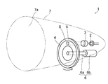
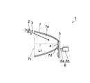
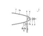
本発明の第1実施形態による照明装置1は、例えば自動車などの前方を照明する前照灯として用いられるものである。照明装置1は図1に示すように、レーザ光源(励起光源)として機能する半導体レーザ2(レーザ発生器)と、半導体レーザ2の前方に配置された導光部材3と、レーザ光(励起光)が照射される蛍光部材4と、蛍光部材4を支持する支持体5と、蛍光部材4を回転させるための回転機構6と、蛍光部材4から出射した蛍光を外部に向かって反射する反射部材7とを備える。なお、後述するように、導光部材3および支持体5は必要に応じて設けられるものであり、無くてもよい。
半導体レーザ2は半導体レーザ素子(図示せず)と半導体レーザ素子が搭載されるパッケージとによって構成されている。半導体レーザ2は例えば約380nm~約460nmの中心波長を有するレーザ光を出射するように構成されている。
導光部材3は半導体レーザ2から出射したレーザ光を蛍光部材4まで導光する機能を有する。導光部材3としては、光ファイバ、レンズ、反射鏡、周囲との屈折率差を利用して内部で光を反射させることにより導光する部材などを用いることができ、これらを複数組み合わせて用いてもよい。なお、導光部材3は必要に応じて設けられるものであり、例えば半導体レーザ2を蛍光部材4の近傍に配置する場合は無くてもよい。
蛍光部材4は例えば5mm~30mm程度の直径を有する円盤状に形成されており、レーザ光(励起光)が照射されることにより蛍光を出射する機能を有する。蛍光部材4は、例えば青紫色のレーザ光を赤色光、緑色光および青色光にそれぞれ変換する3種類の蛍光体粒子を含んでいる。この3種類の蛍光体粒子の各々は、蛍光部材4の全域にわたって略均一に含有されている。また、蛍光部材4に含有される蛍光体粒子は1種類だけであってもよい。この場合も、蛍光体粒子は、蛍光部材4の全域にわたって略均一に含有される。蛍光部材4は、蛍光体粒子をガラスや樹脂などに混ぜて固めたものや、蛍光体粒子を加圧または焼結したものなどを用いることが可能である。
蛍光部材4は円盤状の支持体5に支持されている。蛍光部材4は例えば透光性を有する接着材(図示せず)などを用いて支持体5に固定されていてもよいし、蛍光体粒子を含有する樹脂等を支持体5の表面上に塗布することにより形成されていてもよい。
支持体5の中心部には回転機構6の回転軸6aが固定されている。回転軸6aはモータ6bに連結されており、モータ6bを駆動することにより、回転軸6aが回転して支持体5および蛍光部材4が回転する。蛍光部材4が回転すると、照射領域S(蛍光部材4のレーザ光が照射される領域)が蛍光部材4内で周方向に移動する。これにより、レーザ光が蛍光部材4の特定の領域のみを照射し続けるのを抑制することが可能である。なお、照射領域Sが蛍光部材4内で移動しても、反射部材7に対する照射領域Sの相対位置は変化しない。
蛍光部材4の回転速度は任意に設定することが可能である。例えば、蛍光部材4の回転速度を数回転~数十回転/秒にしてもよいし、1回転以下/秒にしてもよい。また、蛍光部材4を不連続に回転させてもよい。すなわち、所定の角度(例えば30度や170度)だけ蛍光部材4を回転させ、所定の時間回転を停止し、その後、蛍光部材4をさらに所定の角度だけ回転させる、といったように回転と停止とを繰り返してもよい。すなわち、本発明では、レーザ光が蛍光部材4の特定の領域のみを照射し続けるのを抑制することが目的であるため、蛍光部材4の回転速度の自由度を高くすることが可能である。
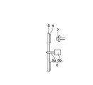
支持体5は光(励起光および蛍光)を遮光するように形成されていてもよい。この場合、支持体5は金属により形成されていてもよく、光を反射する機能を有していてもよい。支持体5が光を遮光するように形成されている場合、蛍光部材4は図2に示すように、支持体5の半導体レーザ2側の面(照射側の面)上に設けられる。
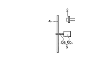
また、支持体5は光を透過するように形成されていてもよい。この場合、蛍光部材4は、図3に示すように支持体5の半導体レーザ2とは反対側の面(照射側とは反対側の面)上に設けられていてもよいし、図2に示すように支持体5の半導体レーザ2側の面上に設けられてもよい。なお図3の場合、支持体5の全体が光を透過する必要はなく、少なくともレーザ光が照射される領域が、光を透過するように形成されていればよい。
また、蛍光部材4は図4に示すように、支持体5の外周面上に形成されていてもよい。また、図5に示すように、支持体5を設けず、蛍光部材4の中心部に回転機構6の回転軸6aを固定してもよい。すなわち、回転機構6が蛍光部材4に取り付けられ、蛍光部材4を直接回転させてもよい。
図1に示すように、反射部材7は蛍光部材4から出射した蛍光を外部に向かって反射する機能を有する。反射部材7の反射面7aは凹状に形成されており、例えば放物面の一部を含むように形成されている。また、反射面7aの焦点が蛍光部材4の照射領域Sと略一致するように、反射部材7が配置されていてもよい。また、蛍光部材4の照射領域Sは、反射面7aの内側に配置されていてもよい。
本実施形態では、上記のように、蛍光部材4を回転させる回転機構6を設け、蛍光部材4を回転させることによって、照射領域Sが蛍光部材4内で移動するので、レーザ光が蛍光部材4の特定の領域のみを照射し続けるのを抑制することができる。このため、蛍光部材4を構成する蛍光体粒子やバインダ樹脂などが劣化するのを抑制することができるので、照明装置1の寿命が短くなるのを抑制することができる。また、レーザ光が蛍光部材4の特定の領域のみを照射し続けるのを抑制することができるので、照射領域Sの温度が上昇するのを抑制することができる。これにより、蛍光部材4の発光効率が低下するのを抑制することができる。
また、蛍光部材4から出射した蛍光を外部に向かって反射する反射部材7を設けることによって、蛍光部材4から出射した蛍光を、所定の方向に反射して照明光として容易に利用することができる。
また、上記のように、蛍光部材4には複数種類(または1種類)の蛍光体粒子が含有されており、複数種類の蛍光体粒子の各々(または1種類の蛍光体粒子)は、蛍光部材4の全域にわたって含有されている。これにより、レーザ光を蛍光部材4のいずれの部分に照射しても、同じ発光スペクトルの蛍光(同じ色の蛍光)が蛍光部材4から出射する。すなわち、レーザ光を蛍光部材4のいずれの部分に照射しても、赤色光、緑色光および青色光が蛍光部材4から出射し白色光が得られる。このため、蛍光部材4を低速で回転させたり、一時的に停止させたとしても、白色光(赤色光、緑色光および青色光)が蛍光部材4から出射する。これにより、蛍光部材4を高速で回転させたり、常時回転させる必要がない。すなわち、回転速度の自由度を高くすることができる。なお例えば、蛍光部材が中心角120度の扇状の3つの領域に分かれており、赤色光、緑色光または青色光を出射する3種類の蛍光体粒子がそれぞれ上記3つの領域に設けられている場合、白色光を得るためには蛍光部材を1秒当たり数十回転以上させる必要がある。
また、上記のように、蛍光部材4を支持する支持体5を設けることによって、蛍光部材4の強度を確保するために蛍光部材4の厚みを大きくする必要がない。また、蛍光部材4に回転機構6を取り付けるためのスペースが必要ないので、蛍光部材4が大型化するのを抑制することができる。また、蛍光部材4で発生する熱を支持体5に放熱させることができるので、蛍光部材4の放熱性を向上させることができる。これにより、蛍光部材4の温度が上昇するのを抑制することができる。
また、上記のように、支持体5を例えば金属により形成すれば、蛍光部材4の放熱性をより向上させることができる。これにより、蛍光部材4の温度が上昇するのをより抑制することができる。この場合、支持体5が光を反射する機能を有していれば、光の利用効率を向上させることができる。
また、上記のように、蛍光部材4の照射領域Sを、反射面7aの焦点と略一致するように配置すれば、照明装置1から外部に出射する光(照明光)を、容易に平行光することができる。
また、上記のように、蛍光部材4の照射領域Sを、反射面7aの内側に配置すれば、蛍光部材4から出射した蛍光の全てまたは大部分を、容易に照明光として利用することができる。
(第2実施形態)
この第2実施形態では、支持体5が光を遮光するように形成されている場合(透光性を有しない場合)について説明する。
この第2実施形態では、支持体5が光を遮光するように形成されている場合(透光性を有しない場合)について説明する。
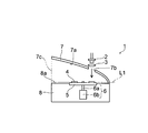
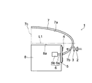
本発明の第2実施形態による照明装置1は図6に示すように、半導体レーザ2と、例えばレンズからなる導光部材3と、蛍光部材4と、支持体5と、回転機構6と、反射部材7と、回転機構6が収納される収納部材8とを備える。
反射部材7の反射面7aは例えば放物面の一部を含むように形成されており、放物面をその頂点と焦点とを結ぶ軸(放物面の回転軸L1)に平行な面で分割したような形状に形成されている。また、反射部材7の所定の位置には、レーザ光を通過させるための貫通穴7bが形成されている。半導体レーザ2は貫通穴7bの外側に配置されている。
収納部材8は金属製の箱状に形成されている。収納部材8は反射部材7に固定されており、収納部材8の上面8aは光を反射する反射面に形成されている。収納部材8を設けることによって、万一、半導体レーザ2から出射したレーザ光が蛍光部材4および支持体5を透過した場合であっても、レーザ光は迷光とならずに収納部材8に閉じ込めることが可能である。
蛍光部材4は放物面の回転軸L1と略平行に配置されているとともに、反射部材7の開口面7cに対して略垂直に配置されている。また、蛍光部材4は反射部材7の反射面7aに対向するように配置されている。また、反射面7aの焦点が蛍光部材4の照射領域Sと略一致するように、反射部材7が設けられている。蛍光部材4は支持体5の半導体レーザ2側の面(照射側の面)上に形成されている。
支持体5は光(レーザ光および蛍光)を遮光する機能を有しており、例えば金属により形成されている。
この照明装置1では、蛍光部材4から照射側(半導体レーザ2側)に出射した光が照明光として利用される。蛍光部材4から出射した光の一部は反射部材7で反射されることなく外部に出射し、残りの光は反射部材7で反射されて外部に出射する。
第2実施形態のその他の構造および効果は、上記第1実施形態と同様である。
(第3実施形態)
この第3実施形態では、上記第2実施形態と異なり、蛍光部材4が反射部材7の開口面7cに対して略平行に配置される場合について説明する。
この第3実施形態では、上記第2実施形態と異なり、蛍光部材4が反射部材7の開口面7cに対して略平行に配置される場合について説明する。
本発明の第3実施形態による照明装置1は図7に示すように、半導体レーザ2と、導光部材3と、蛍光部材4と、支持体5と、回転機構6と、反射部材7とを備える。
反射部材7の頂点付近には、蛍光部材4を配置するための開口部7dが形成されている。支持体5および回転機構6は反射部材7の外側に配置されている。
蛍光部材4は放物面(反射面7a)の回転軸L1に対して略垂直に配置されているとともに、反射部材7の開口面7cに対して略平行に配置されている。また、蛍光部材4は、反射部材7の開口面7c側に向いて配置されている。半導体レーザ2は反射部材7の開口面7cの外側に配置されている。
この照明装置1では、上記第2実施形態と同様、蛍光部材4から照射側(半導体レーザ2側)に出射した光が照明光として利用される。蛍光部材4から出射した光の一部は反射部材7で反射されることなく外部に出射し、残りの光は反射部材7で反射されて外部に出射する。
なお、第3実施形態のその他の構造および効果は、上記第2実施形態と同様である。
(第4実施形態)
この第4実施形態では、上記第2および第3実施形態と異なり、蛍光部材4から出射した蛍光の略全てが反射部材7で反射されて外部に出射する場合について説明する。
この第4実施形態では、上記第2および第3実施形態と異なり、蛍光部材4から出射した蛍光の略全てが反射部材7で反射されて外部に出射する場合について説明する。
本発明の第4実施形態による照明装置1は図8に示すように、半導体レーザ2と、導光部材3と、蛍光部材4と、支持体5と、回転機構6と、反射部材7と、収納部材8とを備える。
反射部材7の所定の位置には、レーザ光を通過させるための貫通穴7bが形成されている。収納部材8の一部は反射部材7の反射面7aの内側に配置されている。
蛍光部材4は放物面(反射面7a)の回転軸L1に対して略垂直に配置されているとともに、反射部材7の反射面7aの頂点側(開口面7cとは反対側)に向いて配置されている。
この照明装置1では、蛍光部材4から照射側(半導体レーザ2側)に出射した光が照明光として利用される。蛍光部材4から出射した蛍光の略全てが反射部材7で反射されて外部に出射する。言い換えると、照明装置1から出射する照明光の全てが、反射部材7で1回以上反射された後、外部に出射される。
第4実施形態のその他の構造は、上記第3実施形態と同様である。
本実施形態では、上記のように、反射部材7は蛍光部材4から出射した蛍光の略全てを1回以上反射して外部に出射する。これにより、蛍光部材4から出射する蛍光の略全てを反射部材7により制御することができるので、所定の領域を効率よく照明することができる。
第4実施形態のその他の効果は、上記第1~第3実施形態と同様である。
(第5実施形態)
この第5実施形態では、上記第4実施形態と異なり、収納部材8が設けられていない場合について説明する。
この第5実施形態では、上記第4実施形態と異なり、収納部材8が設けられていない場合について説明する。
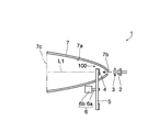
本発明の第5実施形態による照明装置1は図9に示すように、半導体レーザ2と、導光部材3と、蛍光部材4と、支持体5と、回転機構6と、反射部材7とを備えている。
反射部材7の頂点付近には、レーザ光を通過させるための貫通穴7bが形成されている。
蛍光部材4は放物面(反射面7a)の回転軸L1に対して略垂直に配置されているとともに、反射部材7の開口面7cに対して略垂直に配置されている。また、蛍光部材4は、反射部材7の反射面7aの頂点側(開口面7cとは反対側)に向いて配置されている。
蛍光部材4の一部および支持体5の一部は、反射面7aの内側に配置されている。回転機構6は反射部材7の外側に配置されている。
蛍光部材4の外周および支持体5の外周と反射部材7の反射面7aとの間には、反射部材7で反射した蛍光を通過させるための隙間100が形成されている。
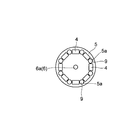
第5実施形態では、反射部材7の反射面7aと支持体5との間の隙間100を通過した光が照明光として利用される。隙間100が十分に大きくない場合、照明装置1の外部に蛍光を十分に取り出せなくなるので、蛍光部材4および支持体5を図10に示すように構成してもよい。具体的には、支持体5に蛍光を通過させるための開口部5aを複数形成する。そして、その開口部5aに、励起光を遮光し蛍光を透過するフィルタ9を設ける。これにより、蛍光部材4から出射した蛍光の外部への取り出し効率が低下するのを抑制することが可能ある。蛍光部材4は図10に示すように複数に分割されていてもよいし、上記第1実施形態などで説明したように円盤状に形成されていてもよい。また、開口部5aや蛍光部材4の形状は、丸や四角に限られず、任意の形状にすることが可能である。励起光の中心波長が例えば約405nmである場合は、フィルタ9として、約425nm以下の波長の光を吸収し約425nmよりも大きい波長の光を透過する、五鈴精工硝子株式会社製のITY-425などを用いることが可能である。
この照明装置1では、上記第4実施形態と同様、蛍光部材4から照射側(半導体レーザ2側)に出射した光が照明光として利用される。蛍光部材4から出射した蛍光の略全てが反射部材7で反射されて外部に出射する。
第5実施形態のその他の構造は、上記第4実施形態と同様である。
本実施形態では、上記のように、蛍光部材4の外周および支持体5の外周と反射部材7の反射面7aとの間には、反射部材7で反射した蛍光を通過させるための隙間100が形成されている。これにより、反射部材7で反射した蛍光を容易に外部に出射させることができる。
第5実施形態のその他の効果は、上記第4実施形態と同様である。
(第6実施形態)
この第6実施形態では、上記第2~第5実施形態と異なり、支持体5が光を透過するように形成されている場合(透光性を有する場合)について説明する。
この第6実施形態では、上記第2~第5実施形態と異なり、支持体5が光を透過するように形成されている場合(透光性を有する場合)について説明する。
本発明の第6実施形態による照明装置1は図11に示すように、半導体レーザ2と、導光部材3と、蛍光部材4と、支持体5と、回転機構6と、反射部材7とを備える。
反射部材7の頂点付近には、蛍光を通過させるための貫通穴7bが形成されている。
蛍光部材4および支持体5は、反射部材7の外側に配置されている。支持体5は光(励起光および蛍光)を透過するように、ガラス板などにより形成されている。
この照明装置1では、蛍光部材4から照射側(半導体レーザ2側)とは反対側に出射した光が照明光として利用される。具体的には、蛍光部材4から照射側に出射した光は照明光として利用されない一方、蛍光部材4から照射側とは反対側(支持体5側)に出射した光は支持体5を透過して照明光として利用される。また、励起光は蛍光部材4を通過したものだけが外部に出射されるので、レーザ光である励起光を蛍光部材4内で十分に拡散させ発光点を大きくした状態で、励起光を外部に出射させることが可能である。これにより、眼に対する安全性を向上させることが可能である。このため、後述する第7実施形態のように励起光を遮光する部材(光学膜など)を用いずとも、安全に使用できる照明装置を実現することが可能である。
第6実施形態のその他の構造および効果は、上記第5実施形態と同様である。
(第7実施形態)
本発明の第7実施形態による照明装置1では図12に示すように、上記第6実施形態と異なり、蛍光部材4の一部および支持体5の一部が反射面7aの内側に配置されている。支持体5は反射部材7を貫通(横断)するように設けられている。このため、上記第5実施形態と異なり、反射部材7の反射面7aと支持体5との間に隙間100は形成されていない。
本発明の第7実施形態による照明装置1では図12に示すように、上記第6実施形態と異なり、蛍光部材4の一部および支持体5の一部が反射面7aの内側に配置されている。支持体5は反射部材7を貫通(横断)するように設けられている。このため、上記第5実施形態と異なり、反射部材7の反射面7aと支持体5との間に隙間100は形成されていない。
支持体5の表面上には、励起光を遮光し蛍光を透過する光学膜(図示せず)が形成されていることが好ましい。このように構成すれば、蛍光部材7から出射した蛍光は支持体5を透過して外部に出射する。その一方、蛍光部材7の表面で反射した励起光は反射面7aおよび光学膜の間で反射を繰り返し、いずれ蛍光部材4に照射され蛍光に変換される。そして、変換された蛍光は支持体5を透過して外部に出射する。このため、励起光を高効率で蛍光に変換することができ、光の利用効率を向上させることが可能となる。
また、支持体5の表面上に、励起光を遮光し蛍光を透過する光学膜を形成すれば、励起光が外部に出射するのを抑制することが可能となる。このため、眼に対する安全性をより向上させることが可能である。
第7実施形態のその他の構造および効果は、上記第6実施形態と同様である。
なお、今回開示された実施形態は、すべての点で例示であって制限的なものではないと考えられるべきである。本発明の範囲は、上記した実施形態の説明ではなく請求の範囲によって示され、さらに請求の範囲と均等の意味および範囲内でのすべての変更が含まれる。
例えば、上記実施形態では、本発明の照明装置を自動車の前照灯に用いた例について示したが、本発明はこれに限らない。本発明の照明装置を、飛行機、船舶、ロボット、バイクまたは自転車や、その他の移動体の前照灯に用いてもよい。
また、上記実施形態では、本発明の照明装置を前照灯に適用した例について示したが、本発明はこれに限らない。本発明の照明装置をダウンライトまたはスポットライトや、その他の照明装置に適用してもよい。
また、上記実施形態では、励起光を可視光に変換した例について示したが、本発明はこれに限らず、励起光を可視光以外の光に変換してもよい。例えば、励起光を赤外光に変換する場合には、セキュリティ用CCDカメラの夜間照明装置などにも適用可能である。
また、上記実施形態では、白色光を出射するように、励起光源(半導体レーザ)および蛍光部材を構成した例について示したが、本発明はこれに限らない。白色光以外の光を出射するように、励起光源および蛍光部材を構成してもよい。
また、上記実施形態では、レーザ光を出射するレーザ発生器として、半導体レーザを用いた例について示したが、本発明はこれに限らず、半導体レーザ以外のレーザ発生器を用いてもよい。
また、上記実施形態で示した数値は一例であり、各数値は限定されない。
また、上記実施形態では、反射部材の反射面を放物面の一部により形成した例について示したが、本発明はこれに限らず、反射面を例えば楕円面の一部により形成してもよい。この場合、蛍光部材の照射領域を反射面の焦点に位置させることにより、照明装置から出射する光を容易に集光することができる。また、反射面を多数の曲面(例えば放物面)からなるマルチリフレクタや、多数の微細な平面が連続して設けられた自由曲面リフレクタなどにより形成してもよい。
また、上記実施形態では、蛍光部材および支持体が円盤状に形成されている場合について示したが、本発明はこれに限らず、蛍光部材および支持体は円盤状以外の形状に形成されていてもよい。例えば、蛍光部材および支持体は正面から見て正方形状や多角形状に形成されていてもよい。
また、上記実施形態では、蛍光部材を回転させることにより、照射領域を蛍光部材内で移動させた例について示したが、本発明はこれに限らない。例えば図13に示した本発明の第1変形例による照明装置のように、蛍光部材4の面方向(例えば半径方向)に回転機構6を移動させる移動機構10をさらに設け、照射領域Sを蛍光部材4の周方向と半径方向との両方向に移動させてもよい。
また、上記第5実施形態では、支持体が透光性を有しない場合について示したが、上記第5実施形態の構造において支持体が透光性を有してもよい。
また、反射部材の開口面に蛍光を透過し励起光(レーザ光)を遮光するフィルタを設けてもよい。このように構成すれば、レーザ光が外部に出射するのを防止することができ、眼に対する安全性を容易に向上させることができる。
また、図14に示した本発明の第2変形例による照明装置のように、蛍光部材4が回転することにより蛍光部材4の周囲の空気を流動させる複数のフィン部11を、支持体5と一体的に設けてもよい。そして、支持体5のうちの例えばフィン部11と蛍光部材4との間に、通気孔5bを複数設けてもよい。このように構成すれば、蛍光部材4および支持体5が回転すると、空気が通気孔5bを通過し流動する。これにより、照射領域の温度が上昇するのをより抑制することができ効果的である。なお、フィン部11は蛍光部材4の周囲に設けられていればよく、蛍光部材4や回転機構6の回転軸6aに取り付けられていてもよい。
また、上記実施形態では、3種類の蛍光体粒子の各々が、蛍光部材の全域にわたって略均一に含有されている例について示したが、本発明はこれに限らない。例えば、蛍光部材が中心角120度の扇状の3つの領域に分かれており、3種類の蛍光体粒子がそれぞれ上記3つの領域に設けられていてもよい。ただし、この場合、白色光を得るためには蛍光部材を1秒当たり数十回転以上させる必要がある。
1 照明装置
2 半導体レーザ(レーザ発生器)
3 導光部材
4 蛍光部材
5 支持体
6 回転機構
7 反射部材
7a 反射面
11 フィン部
100 隙間
S 照射領域
2 半導体レーザ(レーザ発生器)
3 導光部材
4 蛍光部材
5 支持体
6 回転機構
7 反射部材
7a 反射面
11 フィン部
100 隙間
S 照射領域
Claims (15)
- レーザ発生器から出射したレーザ光が照射され、蛍光を出射する蛍光部材と、
前記蛍光部材を回転させる回転機構と、
前記蛍光部材から出射した蛍光を外部に向かって反射する反射部材と、
を備えることを特徴とする照明装置。 - 前記蛍光部材には複数種類または1種類の蛍光体粒子が含有されており、
前記複数種類の蛍光体粒子の各々または前記1種類の蛍光体粒子は、前記蛍光部材の全域にわたって含有されていることを特徴とする請求項1に記載の照明装置。 - 前記蛍光部材は円盤状に形成されていることを特徴とする請求項1または2に記載の照明装置。
- 前記蛍光部材を支持する支持体をさらに備え、
前記回転機構は前記支持体を回転させることにより、前記蛍光部材を回転させることを特徴とする請求項1~3のいずれか1項に記載の照明装置。 - 前記蛍光部材は前記支持体の前記レーザ発生器側の面に設けられていることを特徴とする請求項4に記載の照明装置。
- 前記支持体は前記蛍光を遮光する機能を有することを特徴とする請求項5に記載の照明装置。
- 前記支持体は前記レーザ光を透過する機能を有し、
前記蛍光部材は、前記支持体の前記レーザ発生器とは反対側の面に設けられていることを特徴とする請求項4に記載の照明装置。 - 前記回転機構は前記蛍光部材に取り付けられており、前記蛍光部材を直接的に回転させることを特徴とする請求項1~3のいずれか1項に記載の照明装置。
- 前記反射部材は前記蛍光部材から出射した蛍光の少なくとも一部を1回以上反射して外部に出射することを特徴とする請求項1~8のいずれか1項に記載の照明装置。
- 前記蛍光部材は前記回転機構により回転と停止とを交互に繰り返されることを特徴とする請求項2に記載の照明装置。
- 前記反射部材は、焦点を有する形状に形成された反射面を含み、
前記蛍光部材のうちの前記レーザ光が照射される照射領域は、前記反射面の焦点、または、前記反射面の焦点近傍に配置されていることを特徴とする請求項1~10のいずれか1項に記載の照明装置。 - 前記反射部材は、前記蛍光を反射する凹状の反射面を含み、
前記蛍光部材のうちの前記レーザ光が照射される照射領域は、前記反射面の内側に配置されていることを特徴とする請求項1~11のいずれか1項に記載の照明装置。 - 前記蛍光部材の外周と前記反射部材との間には、前記反射部材で反射した蛍光を通過させるための隙間が形成されていることを特徴とする請求項1~12のいずれか1項に記載の照明装置。
- 前記蛍光部材は前記反射部材を貫通して設けられていることを特徴とする請求項1~13のいずれか1項に記載の照明装置。
- 前記蛍光部材が回転することにより前記蛍光部材の周囲の空気を流動させるフィン部をさらに備えることを特徴とする請求項1~14のいずれか1項に記載の照明装置。
Priority Applications (1)
| Application Number | Priority Date | Filing Date | Title |
|---|---|---|---|
| US14/233,926 US9115873B2 (en) | 2011-08-08 | 2012-07-11 | Lighting device |
Applications Claiming Priority (2)
| Application Number | Priority Date | Filing Date | Title |
|---|---|---|---|
| JP2011172550A JP5261549B2 (ja) | 2011-08-08 | 2011-08-08 | 照明装置 |
| JP2011-172550 | 2011-08-08 |
Publications (1)
| Publication Number | Publication Date |
|---|---|
| WO2013021773A1 true WO2013021773A1 (ja) | 2013-02-14 |
Family
ID=47668293
Family Applications (1)
| Application Number | Title | Priority Date | Filing Date |
|---|---|---|---|
| PCT/JP2012/067665 Ceased WO2013021773A1 (ja) | 2011-08-08 | 2012-07-11 | 照明装置 |
Country Status (3)
| Country | Link |
|---|---|
| US (1) | US9115873B2 (ja) |
| JP (1) | JP5261549B2 (ja) |
| WO (1) | WO2013021773A1 (ja) |
Cited By (3)
| Publication number | Priority date | Publication date | Assignee | Title |
|---|---|---|---|---|
| WO2017081741A1 (ja) * | 2015-11-10 | 2017-05-18 | Necディスプレイソリューションズ株式会社 | 蛍光体ホイールおよびプロジェクタ、蛍光体ホイールの製造方法 |
| CN107036025A (zh) * | 2016-02-03 | 2017-08-11 | 保时捷股份公司 | 前照灯 |
| JPWO2018042560A1 (ja) * | 2016-08-31 | 2018-12-06 | Necディスプレイソリューションズ株式会社 | プロジェクタ及び駆動制御方法 |
Families Citing this family (11)
| Publication number | Priority date | Publication date | Assignee | Title |
|---|---|---|---|---|
| DE102013221953A1 (de) * | 2013-10-29 | 2015-05-21 | Volkswagen Aktiengesellschaft | Leuchtvorrichtung für ein Kraftfahrzeug |
| DE102013226639A1 (de) * | 2013-12-19 | 2015-06-25 | Osram Gmbh | Erzeugen eines Lichtabstrahlmusters in einem Fernfeld |
| DE102014207024A1 (de) * | 2014-04-11 | 2015-10-15 | Osram Gmbh | Leuchtvorrichtung mit Lichtquelle und beabstandetem Leuchtstoffkörper |
| DE102014208660A1 (de) * | 2014-05-08 | 2015-11-12 | Osram Gmbh | Erzeugen eines Lichtabstrahlmusters in einem Fernfeld |
| KR20150145651A (ko) | 2014-06-20 | 2015-12-30 | 에스엘 주식회사 | 차량용 램프 |
| KR20160019809A (ko) * | 2014-08-12 | 2016-02-22 | 현대모비스 주식회사 | 레이져 광학계와 이를 구비한 차량용 램프 |
| JP6459104B2 (ja) * | 2016-03-04 | 2019-01-30 | パナソニックIpマネジメント株式会社 | 波長変換装置及び照明装置 |
| DE102016225361A1 (de) | 2016-12-16 | 2018-06-21 | Osram Gmbh | Beleuchtungsvorrichtung mit leuchtstoffrad |
| CN108286663A (zh) * | 2017-09-06 | 2018-07-17 | 绵阳聚强极风科技有限公司 | 一种激光激发荧光照明装置 |
| US11313671B2 (en) * | 2019-05-28 | 2022-04-26 | Mitutoyo Corporation | Chromatic confocal range sensing system with enhanced spectrum light source configuration |
| WO2024157834A1 (ja) * | 2023-01-24 | 2024-08-02 | パナソニックIpマネジメント株式会社 | 波長変換ホイール、光源装置、及び投写型映像表示装置 |
Citations (11)
| Publication number | Priority date | Publication date | Assignee | Title |
|---|---|---|---|---|
| JP2003295319A (ja) * | 2002-04-04 | 2003-10-15 | Nitto Kogaku Kk | 光源装置及びプロジェクタ |
| JP2004325874A (ja) * | 2003-04-25 | 2004-11-18 | Seiko Epson Corp | 投射型表示装置 |
| JP2004341105A (ja) * | 2003-05-14 | 2004-12-02 | Nec Viewtechnology Ltd | 投写型表示装置 |
| JP2007200782A (ja) * | 2006-01-27 | 2007-08-09 | Ricoh Opt Ind Co Ltd | 蛍光体光源およびその製造方法および光源装置および照明装置 |
| JP2008052070A (ja) * | 2006-08-25 | 2008-03-06 | Samsung Electronics Co Ltd | カラーホイール、可視光光源、投射型画像表示装置、投射型画像表示方法 |
| JP2009539219A (ja) * | 2006-06-02 | 2009-11-12 | コーニンクレッカ フィリップス エレクトロニクス エヌ ヴィ | 有色及び白色光を生成する照明装置 |
| JP2010217566A (ja) * | 2009-03-17 | 2010-09-30 | Casio Computer Co Ltd | 発光装置及び光源装置並びにこの光源装置を用いたプロジェクタ |
| JP2011013316A (ja) * | 2009-06-30 | 2011-01-20 | Casio Computer Co Ltd | 光源装置及びプロジェクタ |
| JP2011124002A (ja) * | 2009-12-08 | 2011-06-23 | Stanley Electric Co Ltd | 光源装置および照明装置 |
| WO2011118536A1 (ja) * | 2010-03-25 | 2011-09-29 | 三洋電機株式会社 | 投写型映像表示装置および光源装置 |
| JP2012074242A (ja) * | 2010-09-28 | 2012-04-12 | Panasonic Corp | 発光装置およびプロジェクタ |
Family Cites Families (3)
| Publication number | Priority date | Publication date | Assignee | Title |
|---|---|---|---|---|
| US8684560B2 (en) * | 2009-11-18 | 2014-04-01 | Stanley Electric Co., Ltd. | Semiconductor light source apparatus and lighting unit |
| US8556437B2 (en) * | 2009-12-17 | 2013-10-15 | Stanley Electric Co., Ltd. | Semiconductor light source apparatus and lighting unit |
| US8496352B2 (en) * | 2010-02-26 | 2013-07-30 | Texas Instruments Incorporated | Wavelength conversion |
-
2011
- 2011-08-08 JP JP2011172550A patent/JP5261549B2/ja active Active
-
2012
- 2012-07-11 US US14/233,926 patent/US9115873B2/en active Active
- 2012-07-11 WO PCT/JP2012/067665 patent/WO2013021773A1/ja not_active Ceased
Patent Citations (11)
| Publication number | Priority date | Publication date | Assignee | Title |
|---|---|---|---|---|
| JP2003295319A (ja) * | 2002-04-04 | 2003-10-15 | Nitto Kogaku Kk | 光源装置及びプロジェクタ |
| JP2004325874A (ja) * | 2003-04-25 | 2004-11-18 | Seiko Epson Corp | 投射型表示装置 |
| JP2004341105A (ja) * | 2003-05-14 | 2004-12-02 | Nec Viewtechnology Ltd | 投写型表示装置 |
| JP2007200782A (ja) * | 2006-01-27 | 2007-08-09 | Ricoh Opt Ind Co Ltd | 蛍光体光源およびその製造方法および光源装置および照明装置 |
| JP2009539219A (ja) * | 2006-06-02 | 2009-11-12 | コーニンクレッカ フィリップス エレクトロニクス エヌ ヴィ | 有色及び白色光を生成する照明装置 |
| JP2008052070A (ja) * | 2006-08-25 | 2008-03-06 | Samsung Electronics Co Ltd | カラーホイール、可視光光源、投射型画像表示装置、投射型画像表示方法 |
| JP2010217566A (ja) * | 2009-03-17 | 2010-09-30 | Casio Computer Co Ltd | 発光装置及び光源装置並びにこの光源装置を用いたプロジェクタ |
| JP2011013316A (ja) * | 2009-06-30 | 2011-01-20 | Casio Computer Co Ltd | 光源装置及びプロジェクタ |
| JP2011124002A (ja) * | 2009-12-08 | 2011-06-23 | Stanley Electric Co Ltd | 光源装置および照明装置 |
| WO2011118536A1 (ja) * | 2010-03-25 | 2011-09-29 | 三洋電機株式会社 | 投写型映像表示装置および光源装置 |
| JP2012074242A (ja) * | 2010-09-28 | 2012-04-12 | Panasonic Corp | 発光装置およびプロジェクタ |
Cited By (7)
| Publication number | Priority date | Publication date | Assignee | Title |
|---|---|---|---|---|
| WO2017081741A1 (ja) * | 2015-11-10 | 2017-05-18 | Necディスプレイソリューションズ株式会社 | 蛍光体ホイールおよびプロジェクタ、蛍光体ホイールの製造方法 |
| WO2017081885A1 (ja) * | 2015-11-10 | 2017-05-18 | Necディスプレイソリューションズ株式会社 | 蛍光体ホイールおよびプロジェクタ、蛍光体ホイールの製造方法 |
| JPWO2017081885A1 (ja) * | 2015-11-10 | 2018-08-30 | Necディスプレイソリューションズ株式会社 | 蛍光体ホイールおよびプロジェクタ、蛍光体ホイールの製造方法 |
| US10288873B2 (en) | 2015-11-10 | 2019-05-14 | Nec Display Solutions, Ltd. | Phosphor wheel, projector, and method of manufacturing phosphor wheel |
| CN107036025A (zh) * | 2016-02-03 | 2017-08-11 | 保时捷股份公司 | 前照灯 |
| JPWO2018042560A1 (ja) * | 2016-08-31 | 2018-12-06 | Necディスプレイソリューションズ株式会社 | プロジェクタ及び駆動制御方法 |
| US10725364B2 (en) | 2016-08-31 | 2020-07-28 | Nec Display Solutions, Ltd. | Projector and drive control method |
Also Published As
| Publication number | Publication date |
|---|---|
| US9115873B2 (en) | 2015-08-25 |
| US20140185272A1 (en) | 2014-07-03 |
| JP5261549B2 (ja) | 2013-08-14 |
| JP2013037867A (ja) | 2013-02-21 |
Similar Documents
| Publication | Publication Date | Title |
|---|---|---|
| JP5261549B2 (ja) | 照明装置 | |
| JP6342279B2 (ja) | 発光装置 | |
| JP5259791B2 (ja) | 発光装置、車両用前照灯、照明装置、及び車両 | |
| JP5323998B2 (ja) | 蛍光体、励起光源、光学システム、およびヒートシンクを備えた照明器具 | |
| JP6258083B2 (ja) | 発光ユニット、発光装置、照明装置および車両用前照灯 | |
| JP5589007B2 (ja) | 発光装置、照明装置および車両用前照灯 | |
| US9291759B2 (en) | Illumination device and vehicle headlight | |
| JP6161877B2 (ja) | 発光装置、車両用前照灯および照明装置 | |
| JP5285038B2 (ja) | 投光構造体および照明装置 | |
| JP2012099280A (ja) | 発光装置、車両用前照灯および照明装置 | |
| JP5373742B2 (ja) | 発光装置、車両用前照灯、照明装置およびレーザ素子 | |
| JP6067629B2 (ja) | 発光装置、照明装置および車両用前照灯 | |
| CN104334965B (zh) | 汽车前大灯和激光汽车前大灯用的光学组件、光源模块 | |
| JP2012084276A (ja) | 発光装置、前照灯および移動体 | |
| JP5891858B2 (ja) | 発光装置及び車両用灯具 | |
| JP5615669B2 (ja) | 車両用灯具 | |
| JP6125776B2 (ja) | 投光装置 | |
| JP5883114B2 (ja) | 発光装置、車両用前照灯および照明装置 | |
| JP2014170758A (ja) | 照明装置、および車両用前照灯 | |
| JP2014007023A (ja) | 車両用灯具 | |
| JP2013197057A (ja) | 照明装置、車両用前照灯および導光部材 | |
| JP2013030380A (ja) | 発光装置 | |
| JP5661886B2 (ja) | 発光装置、車両用前照灯および照明装置 | |
| JP6305967B2 (ja) | 発光装置、照明装置および車両用前照灯 |
Legal Events
| Date | Code | Title | Description |
|---|---|---|---|
| 121 | Ep: the epo has been informed by wipo that ep was designated in this application |
Ref document number: 12821665 Country of ref document: EP Kind code of ref document: A1 |
|
| WWE | Wipo information: entry into national phase |
Ref document number: 14233926 Country of ref document: US |
|
| NENP | Non-entry into the national phase |
Ref country code: DE |
|
| 122 | Ep: pct application non-entry in european phase |
Ref document number: 12821665 Country of ref document: EP Kind code of ref document: A1 |