WO2013021569A1 - 端末装置、基地局装置及び送受信方法 - Google Patents
端末装置、基地局装置及び送受信方法 Download PDFInfo
- Publication number
- WO2013021569A1 WO2013021569A1 PCT/JP2012/004787 JP2012004787W WO2013021569A1 WO 2013021569 A1 WO2013021569 A1 WO 2013021569A1 JP 2012004787 W JP2012004787 W JP 2012004787W WO 2013021569 A1 WO2013021569 A1 WO 2013021569A1
- Authority
- WO
- WIPO (PCT)
- Prior art keywords
- subframe
- unit band
- unit
- downlink data
- terminal
- Prior art date
Links
Images


Classifications
-
- H—ELECTRICITY
- H04—ELECTRIC COMMUNICATION TECHNIQUE
- H04L—TRANSMISSION OF DIGITAL INFORMATION, e.g. TELEGRAPHIC COMMUNICATION
- H04L1/00—Arrangements for detecting or preventing errors in the information received
- H04L1/12—Arrangements for detecting or preventing errors in the information received by using return channel
- H04L1/16—Arrangements for detecting or preventing errors in the information received by using return channel in which the return channel carries supervisory signals, e.g. repetition request signals
- H04L1/18—Automatic repetition systems, e.g. Van Duuren systems
- H04L1/1829—Arrangements specially adapted for the receiver end
- H04L1/1854—Scheduling and prioritising arrangements
-
- H—ELECTRICITY
- H04—ELECTRIC COMMUNICATION TECHNIQUE
- H04L—TRANSMISSION OF DIGITAL INFORMATION, e.g. TELEGRAPHIC COMMUNICATION
- H04L1/00—Arrangements for detecting or preventing errors in the information received
- H04L1/12—Arrangements for detecting or preventing errors in the information received by using return channel
- H04L1/16—Arrangements for detecting or preventing errors in the information received by using return channel in which the return channel carries supervisory signals, e.g. repetition request signals
- H04L1/18—Automatic repetition systems, e.g. Van Duuren systems
- H04L1/1829—Arrangements specially adapted for the receiver end
- H04L1/1861—Physical mapping arrangements
-
- H—ELECTRICITY
- H04—ELECTRIC COMMUNICATION TECHNIQUE
- H04L—TRANSMISSION OF DIGITAL INFORMATION, e.g. TELEGRAPHIC COMMUNICATION
- H04L5/00—Arrangements affording multiple use of the transmission path
- H04L5/003—Arrangements for allocating sub-channels of the transmission path
- H04L5/0053—Allocation of signaling, i.e. of overhead other than pilot signals
- H04L5/0055—Physical resource allocation for ACK/NACK
-
- H—ELECTRICITY
- H04—ELECTRIC COMMUNICATION TECHNIQUE
- H04W—WIRELESS COMMUNICATION NETWORKS
- H04W72/00—Local resource management
- H04W72/12—Wireless traffic scheduling
- H04W72/1263—Mapping of traffic onto schedule, e.g. scheduled allocation or multiplexing of flows
- H04W72/1268—Mapping of traffic onto schedule, e.g. scheduled allocation or multiplexing of flows of uplink data flows
-
- H—ELECTRICITY
- H04—ELECTRIC COMMUNICATION TECHNIQUE
- H04L—TRANSMISSION OF DIGITAL INFORMATION, e.g. TELEGRAPHIC COMMUNICATION
- H04L27/00—Modulated-carrier systems
- H04L27/26—Systems using multi-frequency codes
- H04L27/2601—Multicarrier modulation systems
-
- H—ELECTRICITY
- H04—ELECTRIC COMMUNICATION TECHNIQUE
- H04L—TRANSMISSION OF DIGITAL INFORMATION, e.g. TELEGRAPHIC COMMUNICATION
- H04L5/00—Arrangements affording multiple use of the transmission path
- H04L5/0001—Arrangements for dividing the transmission path
- H04L5/0003—Two-dimensional division
- H04L5/0005—Time-frequency
- H04L5/0007—Time-frequency the frequencies being orthogonal, e.g. OFDM(A), DMT
Definitions
- the present invention relates to a terminal device, a base station device, and a transmission / reception method.
- OFDMA Orthogonal Frequency Frequency Division Multiple Multiple Access
- SCH Synchronization Channel
- BCH Broadcast Channel
- the terminal first secures synchronization with the base station by capturing the SCH. After that, the terminal acquires parameters (for example, frequency bandwidth) unique to the base station by reading the BCH information (see Non-Patent Documents 1, 2, and 3).
- the terminal establishes communication with the base station by making a connection request to the base station after the acquisition of the parameters unique to the base station is completed.
- the base station transmits control information via a downlink control channel such as PDCCH (Physical Downlink Control Channel) as necessary to a terminal with which communication has been established.
- PDCCH Physical Downlink Control Channel
- the terminal then performs “blind determination” on each of a plurality of control information (downlink control information: DL assignment (also referred to as Downlink control information: DCI)) included in the received PDCCH signal. That is, the control information includes a CRC (Cyclic Redundancy Check) part, and this CRC part is masked by the terminal ID of the transmission target terminal in the base station. Therefore, the terminal cannot determine whether or not the received control information is control information destined for the own device until the CRC part of the received control information is demasked with the terminal ID of the own device. In this blind determination, if the CRC calculation is OK as a result of demasking, it is determined that the control information is addressed to the own device.
- DL assignment also referred to as Downlink control information: DCI
- ARQ Automatic Repeat Request
- the terminal feeds back a response signal indicating an error detection result of downlink data to the base station.
- An uplink control channel such as PUCCH (Physical Uplink Control Channel) is used for feedback of this response signal (that is, ACK / NACK signal, which may be simply referred to as “A / N” hereinafter).
- PUCCH Physical Uplink Control Channel
- the control information transmitted from the base station includes resource allocation information including resource information allocated to the terminal by the base station.
- the PDCCH is used for transmitting the control information.
- This PDCCH is composed of one or a plurality of L1 / L2 CCHs (L1 / L2 Control Channel).
- Each L1 / L2CCH is composed of one or a plurality of CCEs (Control Channel Element). That is, CCE is a basic unit for mapping control information to PDCCH.
- one L1 / L2CCH is composed of a plurality (2, 4, 8) of CCEs, a plurality of consecutive CCEs starting from CCEs having even indexes are allocated to the L1 / L2CCH. It is done.
- the base station allocates L1 / L2 CCH to the resource allocation target terminal according to the number of CCEs required for reporting control information to the resource allocation target terminal. Then, the base station maps the physical resource corresponding to the CCE of this L1 / L2CCH and transmits control information.
- each CCE is associated with a PUCCH configuration resource (hereinafter also referred to as a PUCCH resource) in a one-to-one correspondence. Therefore, the terminal that has received the L1 / L2CCH specifies a PUCCH configuration resource corresponding to the CCE that configures the L1 / L2CCH, and transmits a response signal to the base station using this resource.
- a PUCCH configuration resource hereinafter also referred to as a PUCCH resource
- the terminal may use the PUCCH configuration resource corresponding to the CCE having the smallest index among the plurality of PUCCH configuration resources respectively corresponding to the plurality of CCEs (that is, A response signal is transmitted to the base station using a PUCCH configuration resource associated with a CCE having an even-numbered CCE index.
- the terminal may use the PUCCH configuration resource corresponding to the CCE having the smallest index among the plurality of PUCCH configuration resources respectively corresponding to the plurality of CCEs (that is, A response signal is transmitted to the base station using a PUCCH configuration resource associated with a CCE having an even-numbered CCE index.
- downlink communication resources are efficiently used.
- a plurality of response signals transmitted from a plurality of terminals include a ZAC (Zero Auto-correlation) sequence having a Zero Auto-correlation characteristic on the time axis, a Walsh sequence, and a DFT ( Discrete Fourier Transform) sequence and code-multiplexed in PUCCH.
- ZAC Zero Auto-correlation
- W 1 , W 2 , W 3 represents a Walsh sequence with a sequence length of 4
- (F 0 , F 1 , F 2 ) represents a DFT sequence with a sequence length of 3.
- an ACK or NACK response signal is first-order spread to a frequency component corresponding to one SC-FDMA symbol by a ZAC sequence (sequence length 12) on the frequency axis. That is, a response signal component represented by a complex number is multiplied by a ZAC sequence having a sequence length of 12.
- the ZAC sequence as the response signal and the reference signal after the first spreading is a Walsh sequence (sequence length 4: W 0 to W 3, sometimes called a Walsh code sequence), a DFT sequence (sequence length 3 : F 0 to F 3 ) are secondarily diffused corresponding to each.
- a signal having a sequence length of 12 (orthogonal sequence: Walsh sequence or DFT sequence for each component of a response signal after first spreading or a ZAC sequence (Reference Signal Sequence) as a reference signal)
- the second-order spread signal is converted into a signal having a sequence length of 12 on the time axis by IFFT (Inverse Fast Fourier Transform), and CP for each of the signals after IFFT. Is added to form a one-slot signal composed of seven SC-FDMA symbols.
- IFFT Inverse Fast Fourier Transform
- Response signals from different terminals are spread using ZAC sequences corresponding to different cyclic shift amounts (Cyclic Shift Index) or orthogonal code sequences corresponding to different sequence numbers (Orthogonal Cover Index: OC index).
- the orthogonal code sequence is a set of a Walsh sequence and a DFT sequence.
- the orthogonal code sequence may also be referred to as a block-wise spreading code sequence. Therefore, the base station can separate these response signals that have been code-multiplexed by using conventional despreading and correlation processing (see Non-Patent Document 4).
- each terminal blindly determines the downlink allocation control signal addressed to itself in each subframe, reception of the downlink allocation control signal is not always successful on the terminal side.
- a terminal fails to receive a downlink assignment control signal addressed to itself in a certain downlink unit band, the terminal cannot even know whether downlink data addressed to itself exists in the downlink unit band. Therefore, if reception of a downlink assignment control signal in a certain downlink unit band fails, the terminal does not generate a response signal for downlink data in the downlink unit band.
- This error case is defined as DTX (DTX (Discontinuous transmission) of ACK / NACK signals) of the response signal in the sense that the response signal is not transmitted on the terminal side.
- LTE system the base station performs resource allocation independently for uplink data and downlink data. Therefore, in the LTE system, in the uplink, a terminal (that is, a terminal compatible with the LTE system (hereinafter referred to as “LTE terminal”)) must simultaneously transmit a response signal to downlink data and uplink data. A situation that does not occur occurs. In this situation, the response signal and the uplink data from the terminal are transmitted using time-division multiplexing (TDM). As described above, the single carrier characteristic (Single carrier properties) of the transmission waveform of the terminal is maintained by simultaneously transmitting the response signal and the uplink data using TDM.
- TDM time-division multiplexing
- a response signal (“A / N”) transmitted from a terminal is a resource (PUSCH (Physical-Uplink-Shared-CHannel) resource allocated for uplink data).
- PUSCH Physical-Uplink-Shared-CHannel
- Occupying a part (a part of the SC-FDMA symbol adjacent to the SC-FDMA symbol to which the reference signal (RS) is mapped) is transmitted to the base station.
- “Subcarrier” on the vertical axis in FIG. 2 is sometimes called “Virtual subcarrier” or “Time contiguous signal”, and “time” input to a DFT (Discrete Fourier Transform) circuit in the SC-FDMA transmitter.
- DFT Discrete Fourier Transform
- the base station compensates for quality degradation of uplink data due to puncturing by instructing a terminal to a very low coding rate or instructing a very large transmission power.
- 3GPP LTE-Advanced is being standardized to realize higher communication speed than 3GPP LTE.
- the 3GPP LTE-Advanced system (hereinafter sometimes referred to as “LTE-A system”) follows the LTE system.
- LTE-A system a base station and a terminal capable of communicating at a wideband frequency of 40 MHz or more are introduced in order to realize a downlink transmission rate of 1 Gbps or more at the maximum.
- the LTE- The band for the A system is divided into “unit bands” of 20 MHz or less, which is the support bandwidth of the LTE system. That is, the “unit band” is a band having a maximum width of 20 MHz, and is defined as a basic unit of the communication band.
- a “unit band” in the downlink is a band delimited by downlink frequency band information in the BCH broadcast from the base station, Or it may be defined as a band defined by the dispersion width when the downlink control channel (PDCCH) is dispersedly arranged in the frequency domain.
- PDCH downlink control channel
- the “unit band” in the uplink is a band delimited by uplink frequency band information in the BCH broadcast from the base station, or a PUSCH (Physical It may be defined as a basic unit of a communication band of 20 MHz or less including an Uplink (Shared Channel) area and including PUCCH for LTE at both ends.
- the “unit band” may be expressed in English as “Component Carrier (s)” or “Cell” in 3GPPGLTE-Advanced. Moreover, it may be described as CC (s) as an abbreviation.
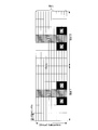
- the downlink unit band and the uplink unit band are the same frequency band, and downlink communication and uplink communication are realized by switching between the downlink and the uplink in a time division manner. Therefore, in the case of the TDD system, the downlink unit band can also be expressed as “downlink communication timing in the unit band”. The uplink unit band can also be expressed as “uplink communication timing in the unit band”. Switching between the downlink unit band and the uplink unit band is based on UL-DL configuration as shown in FIG. In the UL-DL configuration shown in FIG.
- UL-DL configuration can construct a communication system that can flexibly cope with the throughput for downlink communication and the throughput requirement for uplink communication by changing the subframe ratio between downlink communication and uplink communication.
- FIG. 3 shows UL-DL Configurations (Config 0 to 6) having different subframe ratios for downlink communication and uplink communication.
- the downlink communication subframe is represented by “D”
- the uplink communication subframe is represented by “U”
- S special subframe
- the special subframe is a subframe at the time of switching from the downlink communication subframe to the uplink communication subframe.
- downlink data communication may be performed as in the downlink communication subframe.
- subframes (20 subframes) for two frames are used for subframes (upper “D” and “S”) used for downlink communication and uplink communication.
- the sub-frame (lower “U”) is divided into two stages.
- the error detection result (ACK / NACK) for downlink data is reported in an uplink communication subframe that is four or more subframes after the subframe to which the downlink data is assigned.
- the LTE-A system supports communication using a band in which several unit bands are bundled, so-called Carrier Aggregation (CA).
- CA Carrier Aggregation
- the UL-DL configuration can be set for each unit band, but a terminal supporting the LTE-A system (hereinafter referred to as “LTE-A terminal”) has the same UL-DL configuration between a plurality of unit bands. It is designed assuming that is set.
- FIG. 4 is a diagram for explaining an asymmetric carrier aggregation applied to individual terminals and a control sequence thereof.
- the terminal 1 is configured to perform carrier aggregation using two downlink unit bands and one uplink unit band on the left side.
- the terminal 2 is set to use the right uplink unit band in the uplink communication, although the setting is made to use the same two downlink unit bands as the terminal 1.
- LTE-A base station the base station compatible with the LTE-A system
- LTE-A base station the base station compatible with the LTE-A system
- transmission and reception of signals are performed according to the sequence diagram shown in FIG. 4A.
- Terminal 1 synchronizes with the left downlink unit band at the start of communication with the base station, and transmits information on the uplink unit band paired with the left downlink unit band to SIB2 Read from a notification signal called (System Information Block Type 2).
- SIB2 System Information Block Type 2
- the terminal 1 starts communication with the base station, for example, by transmitting a connection request to the base station.
- the base station When determining that it is necessary to assign a plurality of downlink unit bands to the terminal, the base station instructs the terminal to add a downlink unit band. However, in this case, the number of uplink unit bands does not increase, and asymmetric carrier aggregation is started in terminal 1, which is an individual terminal.
- a terminal may receive a plurality of downlink data in a plurality of downlink unit bands at a time.
- LTE-A as a method of transmitting a plurality of response signals for the plurality of downlink data, there are Channel Selection (also referred to as Multiplexing), Bundling, and DFT-S-OFDM (Discrete Fourier Transform spread Orthogonal Frequency Division Multiplexing) format. is there.
- Channel Selection the terminal changes not only the symbol points used for the response signal but also the resources for mapping the response signal, according to the pattern of error detection results for a plurality of downlink data.
- the response signal is transmitted using a predetermined resource (calculating the logical AND of the detection results).
- the terminal collectively encodes response signals for a plurality of downlink data (Joint coding), and transmits the encoded data using the format (non-coding). (See Patent Document 5).
- the terminal may perform feedback of a response signal (ACK / NACK) by either Channel Selection, Bundling, or DFT-S-OFDM according to the number of bits of the error detection result pattern.
- the base station may set the transmission method of the response signal in advance.
- Channel Selection is based on whether the error detection results for a plurality of downlink data for each downlink unit band received in a plurality of downlink unit bands (up to two downlink unit bands) are ACK or NACK, respectively, as shown in FIG.
- PUCCH resource not only the phase point of the response signal (that is, Constellation) point) but also the resource used for transmitting the response signal (hereinafter also referred to as “PUCCH resource”) is changed.
- Bundling is a method of bundling ACK / NACK signals for a plurality of downlink data into one and transmitting them from one predetermined resource (see Non-Patent Documents 6 and 7).
- a signal obtained by bundling ACK / NACK signals for a plurality of downlink data may be referred to as a bundled ACK / NACK signal.
- the following two methods are conceivable as a method of transmitting a response signal on the uplink when the terminal receives downlink allocation control information via the PDCCH and receives downlink data.
- One is a method (Implicit signaling) that transmits a response signal using a PUCCH resource that is associated with a CCE (Control Channel Element) occupied by the PDCCH in a one-to-one relationship (Method 1). That is, when DCI directed to a terminal under the base station is arranged in the PDCCH region, each PDCCH occupies a resource composed of one or a plurality of continuous CCEs. Further, the number of CCEs occupied by the PDCCH (CCE concatenation number: CCE aggregation level) is, for example, one of 1, 2, 4, and 8 depending on the number of information bits of the allocation control information or the channel state of the terminal. Is selected.
- the other is a method in which resources for PUCCH are previously notified from the base station to the terminal (Explicit signaling) (Method 2). That is, in Method 2, the terminal transmits a response signal using the PUCCH resource notified in advance from the base station.
- the terminal transmits a response signal using one of the two unit bands.
- a unit band for transmitting such a response signal is called PCC (Primary Component Carrier) or PCell (Primary Cell).
- PCC Primary Component Carrier
- PCell Primary Cell
- SCC Secondary Component Carrier
- SCell Secondary Cell
- the PCC (PCell) is a unit band that transmits broadcast information (for example, SIB2 (System Information Block type2)) regarding a unit band that transmits a response signal.
- SIB2 System Information Block type2
- a resource for PUCCH common to a plurality of terminals may be notified in advance from the base station to the terminal.
- the terminal may adopt a method of selecting one resource for PUCCH that is actually used based on a 2-bit TPC (Transmit Power Control) command (transmission power control command) included in the DCI in the SCell.
- TPC command is also called ARI (Ack / nack Resource Indicator).
- a certain terminal uses a resource for PUCCH that has been explicitly signaled in a certain subframe, and in another subframe, another terminal uses a resource for the same explicit signal that has been signaled to PUCCH. You can use it.
- the PUCCH resource in the uplink unit band is associated with the first CCE index of the CCE, which is one-to-one associated with the PDCCH occupied by the PDSCH (Physical Downlink Shared Shared CHannel) in the PCC (PCell).
- PUCCH resource in PUCCH region 1 in FIG. 5 is allocated (Implicit signaling).
- a unit band group composed of unit band 1 (PCell) and unit band 2 (SCell) (which may be expressed as “Component carrier set” in English) is set for terminal 1. .
- PCell unit band 1
- SCell unit band 2
- downlink resource allocation information is transmitted from the base station to the terminal 1 via each PDCCH of the unit bands 1 and 2, downlink data is transmitted using resources corresponding to the downlink resource allocation information.
- a response signal indicating an error detection result for a plurality of downlink data in unit band 1 (PCell) and an error detection result for a plurality of downlink data in unit band 2 (SCell) are included in PUCCH region 1 or It is mapped to the PUCCH resource included in the PUCCH region 2.
- the terminal uses one of two types of phase points (BPSK (Binary Phase Shift Shift Keying) mapping) or four types of phase points (QPSK (Quadrature Phase Shift Shift Keying) mapping) as the response signal.
- BPSK Binary Phase Shift Shift Keying
- QPSK Quadrature Phase Shift Shift Keying
- error detection results for a plurality of downlink data in unit band 1 (PCell) and error detection results for a plurality of downlink data in unit band 2 (SCell) are combined by combining PUCCH resources and phase points.
- a pattern can be represented.
- FIG. 6A shows a pattern mapping method of error detection results when there are two unit bands (one PCell and one SCell).
- FIG. 6A assumes a case where the transmission mode is set to any of the following (a), (b), and (c).
- Each unit band is a transmission mode that supports only downlink 1CW transmission.
- B One unit band is a transmission mode that supports only downlink 1CW transmission. Transmission mode in which the other unit band supports up to downlink 2CW transmission
- c Transmission mode in which each unit band supports up to downlink 2CW transmission
- FIG. 6A shows a method of mapping a pattern of error detection results when the above (a) to (c) and (1) to (4) are combined.
- the terminal does not bundle the error detection results, but in the order of (a), (b), (c), 4 patterns, 8 patterns, 16 patterns.
- the error detection result patterns are mapped to two, three, and four PUCCH resources, respectively (Step 3 in FIG. 6A). That is, the terminal reports an error detection result of 1 bit per unit band in which a transmission mode (non-MIMO) that supports only 1 CW (codeword) transmission is set in the downlink, and transmits 2 CW in the downlink.
- a 2-bit error detection result is notified per unit band in which a transmission mode (MIMO) that supports the above is set.
- the terminal maps eight error detection result patterns to four PUCCH resources without bundling the error detection results (see FIG. 6A, Step 3). At that time, the terminal notifies an error detection result of 2 bits per downlink unit band.
- the terminal uses a unit band with a transmission mode that supports up to 2 CW transmission on the downlink.
- the error detection result is bundled in the spatial domain (spatial bundling) (Step 1 in FIG. 6A).
- spatial bundling for example, when the error detection result for at least one CW among the error detection results of 2CW is NACK, the error detection result after spatial bundling is determined as NACK. That is, in spatial bundling, a logical AND (Logical And) is taken with respect to the error detection result of 2CW.
- the terminal maps the error detection result patterns after spatial bundling (eight patterns for (2) and (b), 16 patterns for (2) and (c)) to four PUCCH resources. (Step 3 in FIG. 6A). At that time, the terminal notifies an error detection result of 2 bits per downlink unit band.
- the terminal performs bundling (temporal) in the time domain after spatial bundling (Step 1). Domain bundling (Time-domain bundling) (Step 2 in FIG. 6A). Then, the terminal maps the error detection result pattern after time domain bundling to four PUCCH resources (Step 3 in FIG. 6A). At that time, the terminal notifies an error detection result of 2 bits per downlink unit band.
- the PCell error detection results are four DL subframes (SF1 to SF4), and in the order of (CW0, CW1), (ACK (A), ACK), (ACK, ACK), (NACK (N ), NACK), (ACK, ACK).
- M 4
- the terminal performs spatial bundling at Step 1 in FIG. 6A (portion surrounded by a solid line in FIG. 6B).
- ACK, ACK, NACK, and ACK are obtained in order in the four DL subframes of PCell shown in FIG. 6B.
- the terminal performs time-domain bundling on the 4-bit error detection result pattern (ACK, ACK, NACK, ACK) after spatial bundling obtained in Step 1 (FIG. 6B).
- ACK, ACK, NACK, ACK 4-bit error detection result pattern
- Step 1 FIG. 6B
- the terminal performs space bundling and time domain bundling on the SCell shown in FIG. 6B, and thereby a 2-bit error detection result of (NACK, NACK) is obtained.
- Step 3 of FIG. 6A the terminal combines the 2-bit error detection result patterns after PCell and SCell time domain bundling in the order of PCell and SCell in order of 4-bit error detection result patterns (NACK, ACK, NACK, NACK).
- the terminal determines a PUCCH resource (in this case, h1) and a phase point (in this case, ⁇ j) using the mapping table shown in Step 3 of FIG. 6A for this 4-bit error detection result pattern.
- 3GPP TS 36.211 V10.1.0 “Physical Channels and Modulation (Release 9),” March 2011 3GPP TS 36.212 V10.1.0, “Multiplexing and channel coding (Release 9),” March 2011 3GPP TS 36.213 V10.1.0, “Physical layer procedures (Release 9),” March 2011 Seigo Nakao, Tomofumi Takata, Daichi Imamura, and Katsuhiko Hiramatsu, “Performance enhancement of E-UTRA uplink control channel in fast fading environments,” Proceeding of IEEE VTC 2009 spring, April.
- the LTE-A terminal is designed on the assumption that the same UL-DL configuration is set between a plurality of unit bands.
- the following UL-DL configuration is being considered. That is, the UL-DL configuration of the newly allocated frequency band is set differently from the UL-DL configuration of the existing frequency band, depending on which service the communication carrier attaches importance to.
- UL-DL Configuration for example, Config 3, 4, or 5 in Fig. 3
- Config 3, 4, or 5 in Fig. 3 has a large ratio of DL subframes to UL subframes in a new frequency band.
- the unit band (frequency f1) for which Config 1 is set is PCell
- the unit band (frequency f2) for which Config 3 is set is SCell.
- FIG. 7A shows a method of notifying an error detection result independently in each unit band of PCell and SCell.
- the complexity is low.
- the method of FIG. 7A requires a resource (A / N resource) for transmitting an error detection result (response signal) for each of two unit bands.
- the base station needs to perform decoding processing in parallel (that is, two in parallel) on the error detection results of two unit bands. That is, in the method of FIG. 7A, compared with 3GPPNRelease ⁇ ⁇ 10 (Rel-10) in which only one unit band (1CC) is set in the terminal, double A / N resources and double decoding processing are required. Become.
- the A / N resources for a maximum of 5 CCs are required. Furthermore, in the base station, it becomes necessary to decode the error detection result in a maximum of 5 parallels (1CC error detection result / 1 parallel).
- the timing of UL subframes in each unit band is the same. Therefore, even when the unit band is set to a maximum of 5 CCs for the terminal, the A / N resource amount may be an A / N resource for 1 CC.
- the decoding processing of the error detection result in the base station is only required for one parallel (processing for the error detection result of 1 CC) when a maximum of 5 CCs is set.
- a / N resources and decoding processing amount of up to 5 times are required.
- the method of FIG. 7B is a method in which the error detection results of each unit band are always notified collectively by PCell. That is, in the method of FIG. 7B, the error detection results of both PCell and SCell are transmitted in the UL subframe of PCell.
- the A / N resource to be used may be one CC of the PCell.
- the decoding process of the error detection result in the base station may be one parallel (maximum 5 CC error detection result / one parallel).
- the notification timing of the error detection result of SCell may be different from that in 1CC.
- the earliest notification timing with respect to the error detection result of the data of SCell subframe # 0 in which Config 3 is set is PCell subframe # 7.
- the notification timing for the error detection result for the data of subframe # 0 is subframe # 4.
- the notification timing of the error detection result differs depending on the combination of a plurality of UL-DL configurations and subframe numbers. In this case, the processing related to the error detection results of the base station and the terminal becomes very complicated, and the number of test cases at the development stage of the base station and the terminal increases.
- FIG. 8A to 8D show notification timings of error detection results (A / N) when Configell3 is set in SCell and different UL-DL Configuration is set in PCell.
- the terminal In the methods of FIGS. 8A to 8D, as in the method of FIG. 7B, the terminal always communicates the error detection result for the downlink data of the SCell using the PCell.
- FIG. 8A As in FIG. 7B, Config ⁇ 1 is set in PCell and Config 3 is set in SCell. 8B, FIG. 8C, and FIG. 8D are different in UL-DL configuration set in FIG. 8A and PCell, and Config 0, Config 4, and Config 2 are sequentially set in PCell.
- the terminal paying attention to subframe # 0, it is considered that the terminal notifies an error detection result for downlink data received by the SCell at the earliest timing of the PCell.
- PCell is ConfigPC1 and Config 2 as shown in FIG. 8A and FIG. 8D
- the terminal notifies an error detection result for downlink data received in subframe # 0 of SCell in subframe # 7.
- PCell is Config 0 as shown in FIG.
- the terminal notifies an error detection result for downlink data received in subframe # 0 of SCell in subframe # 4.
- the terminal displays the error detection result for the downlink data received in the subframe # 0 of the SCell in the subframe # 12 (the next frame (one frame is composed of 10 subframes)). Notification is made in subframe # 2).
- the terminal notifies an error detection result for downlink data received in the same subframe of the SCell at different timings of the PCell.
- the notification timing of the error detection result in accordance with the combination must be determined in advance. Since the number of combinations is very large, processing related to notification of error detection results in the base station and the terminal becomes very complicated. In addition, the number of test cases at the development stage of base stations and terminals increases.
- FIG. 9 shows the notification timing of the error detection result according to the combination of the UL-DL configuration of two cells (PCell and SCell) and the subframe number for receiving downlink data (in which subframe of PCell is notified)
- the data table showing is shown.
- 9A to 9G are data tables when the SCell's UL-DL configuration is Config 0 to Config 6 respectively.
- a plurality of rows of each data table indicate notification timings when the PCell UL-DL Configuration is Config 0 to Config 6, respectively.
- the plurality of columns respectively show notification timings in the case of error detection results for downlink data received in SCell subframe numbers # 0 to # 9.
- the notification timing when the same UL-DL configuration is set in two cells is indicated by hatching, and the notification timing scattered by the combination of UL-DL configurations is a dot network. It is indicated by a hanger.
- the notification timing of the error detection result for the received data of SCell subframe # 0 is subframe # 4 when PCell is Config 0, Config 3, or Config 6.
- the notification timing is subframe # 7.
- the notification timing is subframe # 12 (that is, subframe # 2 of the next frame (one frame is composed of 10 subframes)).
- the notification timing of the error detection result for the received data of the SCell subframe # 9 is subframe # 13 (that is, subframe # 3 of the next frame) when the PCell is Config 0, Config 1, Config 4 or Config 6. It is.
- PCell is Config 2 the notification timing is subframe # 17 (that is, subframe # 7 of the next frame).
- PCell is Config 5 the notification timing is subframe # 22 (that is, subframe # 2 of the next frame).
- An object of the present invention is when ARQ is applied in communication using a plurality of unit bands, and the UL-DL configuration (ratio of UL subframes and DL subframes) set for each unit band is different. In this case, the notification timing of the error detection result of the downlink data received by the SCell is not scattered in a complicated manner. And it is providing the terminal device, base station apparatus, and transmission / reception method which can simplify the transmission process of the response signal in a terminal, and the reception process of the response signal in a base station by it.
- a terminal apparatus uses a plurality of unit bands including a first unit band (for example, a PCell unit band) and a second unit band (for example, a SCell unit band)
- a terminal device configured to communicate, wherein each unit band is configured with a configuration pattern that defines an arrangement of a plurality of types of subframes including a downlink communication subframe and an uplink communication subframe within one frame,
- Receiving means for receiving downlink data in a band; error detecting means for detecting errors in each downlink data; generating means for generating a response signal indicating an error detection result of each downlink data obtained by the error detecting means; Control means for transmitting the response signal to the base station apparatus, and the first unit band and the second unit band are different from each other.
- the control unit can transmit a response signal to the downlink data received in the second unit band in the first unit band and the downlink data received in the second unit band.
- the subframe of the first unit band is a downlink communication subframe and the subframe of the second unit band is an uplink communication subframe during a reference transmission period of a response signal to A response signal to the data is transmitted in a specific uplink communication subframe set in the first unit band, and the specific uplink communication subframe is a minimum in which a switching point of the type of the subframe appears periodically.
- a configuration is adopted in which one uplink transmission subframe is set for each period and is arranged in the same period within the minimum period.
- a base station apparatus and a terminal apparatus transmit and receive radio signals using a plurality of unit bands including a first unit band and a second unit band, and the unit bands are transmitted.
- a transmission / reception method in which a configuration pattern that defines the arrangement of a plurality of types of subframes including a downlink communication subframe and an uplink communication subframe within one frame is set, and the base station apparatus includes the first unit
- Different configuration patterns are set for the band and the second unit band
- the terminal apparatus receives downlink data in the plurality of unit bands, detects an error in each downlink data, and obtains each downlink data obtained
- the response signal indicating the error detection result of the second unit band is received and a period necessary for generating the response signal has elapsed since the reception of the downlink data of the second unit band
- the subband of the higher band is a downlink communication subframe and the subframe of the second unit band is an uplink communication subframe
- the present invention when ARQ is applied in communication using a plurality of unit bands, and the UL-DL configuration (ratio of UL subframes and DL subframes) set for each unit band is different. Therefore, it is avoided that the notification timing of the error detection result of the downlink data received by the SCell is scattered in a complicated manner. Thereby, the transmission process of the response signal at the terminal and the reception process of the response signal at the base station can be simplified.
- diffusion method of a response signal and a reference signal The figure which shows the operation
- the figure which shows the notification timing of the response signal when different UL-DL Configuration is set in SCell and PCell The figure showing the notification timing of the response signal according to the combination of UL-DL configuration of PCell and SCell and subframe number for receiving downlink data
- the block diagram which shows the structure of the base station which concerns on Embodiment 1 of this invention.
- the block diagram which shows the structure of the terminal which concerns on Embodiment 1 of this invention.
- the figure which shows the notification timing of the response signal which concerns on Embodiment 1 of this invention The figure showing the notification timing of the response signal according to the combination of the UL-DL configuration of PCell and SCell and the subframe number for receiving downlink data according to Embodiment 1 of the present invention Flowchart for explaining a method for determining a response signal notification timing according to the first embodiment of the present invention.
- the figure showing the notification timing of the response signal according to the combination of the subframe number which receives UL-DL Configuration of PCell and SCell and downlink data according to Embodiment 2 of the present invention Flowchart for explaining a method for determining a response signal notification timing according to the second embodiment of the present invention.
- the figure explaining the notification timing of the response signal according to the presence or absence of UL grant according to the third embodiment of the present invention and the notification timing similar to the conventional standard according to the presence or absence of UL grant The block diagram which shows the main structures of the base station which concerns on Embodiment 4 of this invention.
- the figure explaining the delay of the response signal which concerns on embodiment of this invention are examples of the response signal according to the combination of the subframe number which receives UL-DL Configuration of PCell and SCell and downlink data according to Embodiment 2 of the present invention.
- FIG. 10 is a main configuration diagram of terminal 200 according to the present embodiment.
- Terminal 200 communicates with base station 100 using a plurality of unit bands including a first unit band and a second unit band.
- each unit band set in the terminal 200 is a subframe configuration pattern constituting one frame, and is used for downlink communication subframes (DL subframes) used for downlink communication and uplink communication.
- a configuration pattern (DL-UL Configuration) including the uplink communication subframe (UL subframe) to be used is set.
- extraction section 204 receives downlink data in a plurality of unit bands
- CRC section 211 detects an error in each downlink data
- response signal generation section 212 receives each downlink data obtained in CRC section 211.
- a response signal is generated using the data error detection result, and the control unit 208 transmits the response signal to the base station 100.
- the control unit 208 transmits a response signal including an error detection result for the data received in the second unit band in the subframe # 2 or the subframe # 7 of the first unit band.
- Different UL DL Configurations can be set for the first unit band and the second unit band.
- the UL DL Configuration set in the first unit band may be referred to as “first UL DL Configuration” or “first configuration pattern”.
- the UL DL Configuration set in the second unit band may be referred to as “second UL DL Configuration” or “second configuration pattern”.
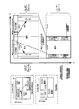
- FIG. 11 is a block diagram showing a configuration of base station 100 according to the present embodiment.
- the base station 100 includes a control unit 101, a control information generation unit 102, an encoding unit 103, a modulation unit 104, an encoding unit 105, a data transmission control unit 106, a modulation unit 107, Mapping unit 108, IFFT (Inverse Fast Fourier Transform) unit 109, CP adding unit 110, radio transmitting unit 111, radio receiving unit 112, CP removing unit 113, PUCCH extracting unit 114, and despreading unit 115
- a retransmission control signal generation unit 122 includes a retransmission control signal generation unit 122.
- the control unit 101 transmits, to a resource allocation target terminal (hereinafter also referred to as “destination terminal” or simply “terminal”) 200, downlink resources for transmitting control information (that is, downlink control information allocation resources), and downlink A downlink resource (that is, a downlink data allocation resource) for transmitting line data is allocated (assigned).
- This resource allocation is performed in the downlink unit band included in the unit band group set in the resource allocation target terminal 200.
- the downlink control information allocation resource is selected in a resource corresponding to a downlink control channel (PDCCH) in each downlink unit band.
- the downlink data allocation resource is selected in a resource corresponding to a downlink data channel (PDSCH) in each downlink unit band.
- the control unit 101 allocates different resources to each of the resource allocation target terminals 200.
- the downlink control information allocation resource is equivalent to the above-mentioned L1 / L2CCH. That is, the downlink control information allocation resource is composed of one or a plurality of CCEs.
- control unit 101 determines a coding rate used when transmitting control information to the resource allocation target terminal 200. Since the data amount of control information differs according to the coding rate, downlink control information allocation resources having a number of CCEs to which control information of this data amount can be mapped are allocated by the control unit 101.
- control part 101 outputs the information regarding a downlink data allocation resource with respect to the control information generation part 102.
- FIG. the control unit 101 outputs information on the coding rate to the coding unit 103.
- Control section 101 also determines the coding rate of transmission data (that is, downlink data) and outputs the coding rate to coding section 105.
- the control unit 101 outputs information on the downlink data allocation resource and the downlink control information allocation resource to the mapping unit 108.
- the control unit 101 controls the downlink data and the downlink control information for the downlink data to be mapped to the same downlink unit band.
- the control information generation unit 102 generates control information including information on downlink data allocation resources and outputs the control information to the encoding unit 103. This control information is generated for each downlink unit band. Further, when there are a plurality of resource allocation target terminals 200, the control information includes the terminal ID of the destination terminal 200 in order to distinguish the resource allocation target terminals 200 from each other. For example, a CRC bit masked with the terminal ID of the destination terminal 200 is included in the control information. This control information may be referred to as “downlink control information (DCI)” or “downlink control information (DCI)”.
- DCI downlink control information
- DCI downlink control information
- the encoding unit 103 encodes the control information according to the encoding rate received from the control unit 101, and outputs the encoded control information to the modulation unit 104.
- Modulation section 104 modulates the encoded control information and outputs the obtained modulated signal to mapping section 108.
- the encoding unit 105 receives the transmission data (that is, downlink data) for each destination terminal 200 and the coding rate information from the control unit 101 as input, encodes the transmission data, and outputs the transmission data to the data transmission control unit 106. However, when a plurality of downlink unit bands are allocated to destination terminal 200, encoding section 105 encodes transmission data transmitted in each downlink unit band, and transmits the encoded transmission data as data transmission. Output to the control unit 106.
- the data transmission control unit 106 holds the encoded transmission data and outputs it to the modulation unit 107 during the initial transmission.
- the encoded transmission data is held for each destination terminal 200.
- Transmission data to one destination terminal 200 is held for each downlink unit band to be transmitted. As a result, not only retransmission control of the entire data transmitted to the destination terminal 200 but also retransmission control for each downlink unit band is possible.
- data transmission control section 106 when data transmission control section 106 receives NACK or DTX for downlink data transmitted in a certain downlink unit band from retransmission control signal generation section 122, data transmission control section 106 outputs retained data corresponding to this downlink unit band to modulation section 107. To do. When data transmission control section 106 receives ACK for downlink data transmitted in a certain downlink unit band from retransmission control signal generation section 122, data transmission control section 106 deletes the retained data corresponding to this downlink unit band.
- Modulation section 107 modulates the encoded transmission data received from data transmission control section 106 and outputs the modulated signal to mapping section 108.
- the mapping unit 108 maps the modulation signal of the control information received from the modulation unit 104 to the resource indicated by the downlink control information allocation resource received from the control unit 101, and outputs it to the IFFT unit 109.
- mapping section 108 assigns a modulation signal of transmission data received from modulation section 107 to a resource (PDSCH (downlink data channel)) indicated by a downlink data allocation resource (that is, information included in control information) received from control section 101. Mapping is performed and output to the IFFT unit 109.
- PDSCH downlink data channel
- Control information and transmission data mapped to a plurality of subcarriers in a plurality of downlink unit bands by the mapping unit 108 are converted from a frequency domain signal to a time domain signal by the IFFT unit 109.
- the converted signal is converted into an OFDM signal by adding a CP at the CP adding unit 110, and then subjected to transmission processing such as D / A (Digital-to-Analog) conversion, amplification, and up-conversion at the wireless transmission unit 111. And transmitted to the terminal 200 via the antenna.
- the radio reception unit 112 receives an uplink response signal or reference signal transmitted from the terminal 200 via an antenna, and performs reception processing such as down-conversion and A / D conversion on the uplink response signal or reference signal.
- the CP removal unit 113 removes the CP added to the uplink response signal or the reference signal after reception processing.
- the PUCCH extraction unit 114 extracts a PUCCH region signal corresponding to a bundle ACK / NACK resource that has been previously notified to the terminal 200 from the PUCCH signal included in the received signal.
- the bundle ACK / NACK resource is a resource to which a bundle ACK / NACK signal is to be transmitted, and is a resource that adopts a DFT-S-OFDM format configuration.
- the PUCCH extraction unit 114 performs the data portion of the PUCCH region corresponding to the bundle ACK / NACK resource (that is, the SC-FDMA symbol in which the bundle ACK / NACK signal is arranged) and the reference signal portion (that is, the bundle).
- PUCCH extraction section 114 outputs the extracted data portion to bundle A / N despreading section 119 and outputs the reference signal portion to despreading section 115-1.
- the PUCCH extraction unit 114 uses the A / N resource associated with the CCE occupied by the PDCCH used for transmission of the downlink allocation control information (DCI) from the PUCCH signal included in the received signal and the terminal in advance. A plurality of PUCCH regions corresponding to a plurality of A / N resources notified to 200 are extracted.
- the A / N resource is a resource to which A / N is to be transmitted.
- the PUCCH extraction unit 114 demodulates the data part (SC-FDMA symbol in which the uplink control signal is allocated) and the reference signal part (uplink control signal for the A / N resource). SC-FDMA symbols in which reference signals are arranged) are extracted.
- PUCCH extraction section 114 outputs both the extracted data portion and reference signal portion to despreading section 115-2.
- the response signal is received using the resource selected from the PUCCH resource associated with the CCE and the specific PUCCH resource notified to the terminal 200.
- sequence control unit 116 may be used for spreading each of the A / N, the reference signal for the A / N notified from the terminal 200, and the reference signal for the bundled ACK / NACK signal. Long ZAC sequence). Also, sequence control section 116 specifies correlation windows corresponding to resources (hereinafter referred to as “reference signal resources”) in which reference signals can be arranged in PUCCH resources that terminal 200 may use. Sequence control section 116 then outputs information indicating a correlation window corresponding to a reference signal resource in which a reference signal can be arranged in bundled ACK / NACK resources and Base sequence to correlation processing section 117-1. Sequence control section 116 outputs information indicating a correlation window corresponding to the reference signal resource and Base sequence to correlation processing section 117-1. In addition, sequence control section 116 outputs information indicating a correlation window corresponding to the A / N resource in which the A / N and the reference signal for A / N are arranged and Base sequence to correlation processing section 117-2.
- reference signal resources herein
- the despreading unit 115-1 and the correlation processing unit 117-1 perform processing of the reference signal extracted from the PUCCH region corresponding to the bundle ACK / NACK resource.
- despreading section 115-1 despreads the reference signal portion with a Walsh sequence that terminal 200 should use for secondary spreading in the reference signal of bundled ACK / NACK resource, and correlates the signal after despreading Output to the unit 117-1.
- Correlation processing section 117-1 uses the information indicating the correlation window corresponding to the reference signal resource and Base sequence, and the signal input from despreading section 115-1 and the possibility of being used for primary spreading in terminal 200 Find the correlation value with the base sequence where Correlation processing section 117-1 outputs the correlation value to bundle A / N determination section 121.
- the despreading unit 115-2 and the correlation processing unit 117-2 perform processing of reference signals and A / N extracted from a plurality of PUCCH regions corresponding to a plurality of A / N resources.
- despreading section 115-2 despreads the data part and reference signal part with Walsh sequence and DFT sequence that terminal 200 should use for secondary spreading in the data part and reference signal part of each A / N resource. Then, the despread signal is output to the correlation processing unit 117-2.
- Correlation processing section 117-2 uses the signal indicating correlation window corresponding to each A / N resource and the base sequence, and the signal input from despreading section 115-2 and is used for primary spreading in terminal 200. Correlation values with possible Base sequence are obtained. Correlation processing section 117-2 outputs each correlation value to A / N determination section 118.
- a / N determination section 118 uses which A / N resource is transmitted from terminal 200, or which A / N It is determined whether N resources are also used. If the A / N determination unit 118 determines that a signal is transmitted from any one of the A / N resources from the terminal 200, the A / N determination unit 118 uses a component corresponding to the reference signal and a component corresponding to A / N. The synchronous detection is performed, and the result of the synchronous detection is output to the retransmission control signal generation unit 122. On the other hand, if the terminal 200 determines that no A / N resource is used, the A / N determination unit 118 outputs to the retransmission control signal generation unit 122 that the A / N resource is not used. .
- the bundle A / N despreading section 119 despreads the bundle ACK / NACK signal corresponding to the data portion of the bundle ACK / NACK resource input from the PUCCH extraction section 114 using the DFT sequence, and outputs the signal to the IDFT section 120 To do.
- the IDFT unit 120 converts the bundle ACK / NACK signal on the frequency domain input from the bundle A / N despreading unit 119 into a signal on the time domain by IDFT processing, and converts the bundle ACK / NACK signal on the time domain to The data is output to the bundle A / N determination unit 121.
- the bundle A / N determination unit 121 converts the bundle ACK / NACK signal corresponding to the data portion of the bundle ACK / NACK resource input from the IDFT unit 120 to the bundle ACK / NACK signal input from the correlation processing unit 117-1. Demodulate using reference signal information. Further, the bundle A / N determination unit 121 decodes the demodulated bundle ACK / NACK signal and outputs the decoded result to the retransmission control signal generation unit 122 as bundle A / N information. However, when the bundle A / N determination unit 121 determines that the correlation value input from the correlation processing unit 117-1 is smaller than the threshold value and no signal is transmitted from the terminal 200 using the bundle A / N resource. Is sent to the retransmission control signal generator 122.
- the retransmission control signal generation unit 122 determines whether or not the data transmitted in the downlink unit band (downlink data) should be retransmitted, and generates a retransmission control signal based on the determination result. This determination is performed based on information input from the bundle A / N determination unit 121, information input from the A / N determination unit 118, and notification timing information of an error detection result.
- the notification timing information of the error detection result is determined according to a combination of a plurality of UL-DL configurations defined between the base station 100 and the terminal 200 in advance and the subframe timing.
- retransmission control signal generation section 122 determines that it is necessary to retransmit downlink data transmitted in a certain downlink unit band, retransmission control signal generation section 122 generates a retransmission control signal indicating a retransmission instruction for the downlink data. The retransmission control signal is output to the data transmission control unit 106. If retransmission control signal generation section 122 determines that there is no need to retransmit downlink data transmitted in a certain downlink unit band, retransmission control signal generation section 122 does not retransmit the downlink data transmitted in that downlink unit band. Is generated, and the retransmission control signal is output to the data transmission control unit 106. The details of the notification timing information of the error detection result for a combination of a plurality of UL-DL configurations and subframe timings used for determining whether or not to retransmit data in retransmission control signal generation section 122 will be described later.
- FIG. 12 is a block diagram showing a configuration of terminal 200 according to the present embodiment.
- a terminal 200 includes a radio reception unit 201, a CP removal unit 202, an FFT (Fast Fourier Transform) unit 203, an extraction unit 204, a demodulation unit 205, a decoding unit 206, a determination unit 207, Control unit 208, demodulation unit 209, decoding unit 210, CRC unit 211, response signal generation unit 212, encoding & modulation unit 213, primary spreading units 214-1, 214-2, secondary Spreading units 215-1 and 215-2, DFT unit 216, spreading unit 217, IFFT units 218-1, 182-2, and 218-3, CP adding units 219-1, 219-2, and 219-3 A time multiplexing unit 220, a selection unit 221, and a wireless transmission unit 222.
- FFT Fast Fourier Transform
- the radio reception unit 201 receives an OFDM signal transmitted from the base station 100 via an antenna, and performs reception processing such as down-conversion and A / D conversion on the received OFDM signal.
- the received OFDM signal includes a PDSCH signal (downlink data) assigned to a resource in PDSCH or a PDCCH signal assigned to a resource in PDCCH.
- CP removing section 202 removes the CP added to the OFDM signal after reception processing.
- the FFT unit 203 performs FFT on the received OFDM signal and converts it into a frequency domain signal, and outputs the obtained received signal to the extracting unit 204.
- the extraction unit 204 extracts a downlink control channel signal (PDCCH signal) from the received signal received from the FFT unit 203 according to the input coding rate information. That is, since the number of CCEs (or R-CCEs) constituting the downlink control information allocation resource changes according to the coding rate, the extraction unit 204 uses the number of CCEs corresponding to the coding rate as the extraction unit, A control channel signal is extracted. Further, the downlink control channel signal is extracted for each downlink unit band. The extracted downlink control channel signal is output to demodulation section 205.
- PDCCH signal downlink control channel signal
- the extraction unit 204 extracts downlink data (downlink data channel signal (PDSCH signal)) from the received signal based on information on downlink data allocation resources addressed to the own device received from the determination unit 207 described later, and a demodulation unit To 209. As described above, the extraction unit 204 receives downlink allocation control information (DCI) mapped to the PDCCH, and receives downlink data on the PDSCH.
- DCI downlink allocation control information
- the demodulation unit 205 demodulates the downlink control channel signal received from the extraction unit 204 and outputs the obtained demodulation result to the decoding unit 206.
- the decoding unit 206 decodes the demodulation result received from the demodulation unit 205 according to the input coding rate information, and outputs the obtained decoding result to the determination unit 207.
- the determination unit 207 when detecting the control information addressed to the own device (that is, downlink allocation control information), the determination unit 207 notifies the control unit 208 that an ACK / NACK signal is generated (exists). In addition, when the determination unit 207 detects control information addressed to itself from the PDCCH signal, the determination unit 207 outputs information on the CCE occupied by the PDCCH to the control unit 208.
- the control unit 208 specifies an A / N resource associated with the CCE from the information on the CCE input from the determination unit 207. Then, the control unit 208 obtains the Base sequence and cyclic shift amount corresponding to the A / N resource associated with the CCE or the A / N resource previously notified from the base station 100, and the primary spreading unit 214-1 The Walsh sequence and DFT sequence corresponding to the A / N resource are output to the secondary spreading section 215-1. Control unit 208 also outputs frequency resource information of A / N resources to IFFT unit 218-1.
- control unit 208 determines to transmit the bundled ACK / NACK signal using the bundled ACK / NACK resource, the reference signal portion (reference signal resource) of the bundled ACK / NACK resource notified from the base station 100 in advance. Are output to the primary spreading section 214-2, and the Walsh sequence is output to the secondary spreading section 215-2. Further, control unit 208 outputs the frequency resource information of the bundled ACK / NACK resource to IFFT unit 218-2.
- control unit 208 outputs the DFT sequence used for spreading the data part of the bundled ACK / NACK resource to the spreading unit 217, and outputs the frequency resource information of the bundled ACK / NACK resource to the IFFT unit 218-3.
- control unit 208 selects either the bundled ACK / NACK resource or the A / N resource, and instructs the selection unit 221 to output the selected resource to the wireless transmission unit 222. Furthermore, the control unit 208 instructs the response signal generation unit 212 to generate either a bundled ACK / NACK signal or an ACK / NACK signal according to the selected resource.
- Demodulation section 209 demodulates the downlink data received from extraction section 204, and outputs the demodulated downlink data to decoding section 210.
- Decoding section 210 decodes the downlink data received from demodulation section 209 and outputs the decoded downlink data to CRC section 211.
- the response signal generation unit 212 receives a response signal based on the downlink data reception status (downlink data error detection result) in each downlink unit band and the notification timing information of the error detection result, which are input from the CRC unit 211 Is generated.
- the notification timing information of the error detection result is determined according to a combination of a plurality of UL-DL configurations defined between the base station 100 and the terminal 200 in advance and the subframe timing.
- the response signal generation unit 212 includes a bundled ACK / NACK in which each error detection result for each downlink unit band is included as individual data. Generate a signal.
- response signal generation section 212 when instructed by control section 208 to generate an ACK / NACK signal, response signal generation section 212 generates an ACK / NACK signal of one symbol. Then, the response signal generation unit 212 outputs the generated response signal to the encoding / modulation unit 213.
- the details of the notification timing information of the error detection result for a combination of a plurality of UL-DL configurations and subframe timings used in the response signal generation unit 212 will be described later.
- the encoder / modulator 213 When a bundle ACK / NACK signal is input, the encoder / modulator 213 encodes and modulates the input bundle ACK / NACK signal, generates a 12-symbol modulated signal, and outputs the modulated signal to the DFT unit 216. To do. Also, when a 1-symbol ACK / NACK signal is input, encoding / modulation section 213 modulates the ACK / NACK signal and outputs it to primary spreading section 214-1.
- the primary spreading sections 214-1 and 214-2 corresponding to the reference signal resources of the A / N resource and the bundled ACK / NACK resource correspond to the ACK / NACK signal or the reference signal according to the instruction of the control section 208.
- the base signals are spread by the base sequence and the spread signals are output to the secondary spreading sections 215-1 and 215-2.
- Secondary spreading sections 215-1 and 215-2 based on an instruction from control section 208, spread the input primary spread signal using a Walsh sequence or a DFT sequence, and send it to IFFT sections 218-1 and 181-2. Output.
- the DFT unit 216 obtains 12 signal components on the frequency axis by collecting 12 input time-series bundle ACK / NACK signals and performing DFT processing. Then, the DFT unit 216 outputs the 12 signal components to the spreading unit 217.
- Spreading section 217 spreads the 12 signal components input from DFT section 216 using the DFT sequence specified by control section 208, and outputs the result to IFFT section 218-3.
- the IFFT units 218-1, 218-2, and 218-3 perform IFFT processing in accordance with the instruction from the control unit 208 in association with the input signal to the frequency position to be arranged.
- signals ie, ACK / NACK signal, A / N resource reference signal, bundle ACK / NACK resource reference signal, bundle ACK / NACK
- Signal is converted to a time domain signal.
- CP adding sections 219-1, 219-2, and 219-3 add the same signal as the tail part of the signal after IFFT to the head of the signal as a CP.
- the time multiplexing unit 220 receives the bundle ACK / NACK signal input from the CP addition unit 219-3 (that is, the signal transmitted using the data portion of the bundle ACK / NACK resource) and the CP addition unit 219-2.
- the bundled ACK / NACK resource reference signal is time-multiplexed with the bundled ACK / NACK resource. Then, the time multiplexing unit 220 outputs the obtained signal to the selection unit 221.
- the selection unit 221 selects either the bundle ACK / NACK resource input from the time multiplexing unit 220 or the A / N resource input from the CP addition unit 219-1 according to the instruction of the control unit 208, and selects the selected resource
- the signal assigned to is output to the wireless transmission unit 222.
- the radio transmission unit 222 performs transmission processing such as D / A conversion, amplification, and up-conversion on the signal received from the selection unit 221, and transmits the signal from the antenna to the base station 100.
- terminal 200 when 2CC-specific configuration is set, terminal 200 always reports an error detection result for downlink data received in the SCell unit band in subframe # 2 or subframe # 7 in the PCell unit band. To do. That is, in the first embodiment, in the case of 2CC-specific configuration setting, the error detection result for the SCell downlink data is notified, and the error detection result of the downlink data received in the same subframe in 1CC-SCell configuration setting is notified. The timing to do is not the same.
- the terminal 200 notifies the error detection result for the downlink data of the SCell in the PCell unit band at the same timing as the notification timing of the 1CC-SCell configuration setting.
- the notification timing of the error detection result for the downlink data of the SCell is not the same in the case of 2CC-specific configuration setting and in the case of 2CC-same configuration setting.
- the Special subframe includes a DL / UL switching point (guard period, also referred to as Guard Period (GP)).
- Config 0 Config 1
- Config 2 Config 6
- the DL / UL switching point appears at a cycle of 5 ms.
- Config-3, Config-4, and Config-5 DL / UL switching points appear at a cycle of 10 ms.
- the UL-DL Configuration in which the minimum cycle in which the Special subframe appears periodically is a 5 ms cycle
- UL-DL Configuration a UL-DL Configuration in which the minimum cycle in which the Special subframe appears periodically is a 10 ms cycle
- a UL-DL Configuration in which the minimum cycle in which the Special subframe appears periodically is a 10 ms cycle
- 10 ms cycle UL-DL Configuration a UL-DL Configuration in which the minimum cycle in which the Special subframe appears periodically is a 10 ms cycle
- the reason why there are two types of cycles is to allow the ratio of various UL subframes and DL subframes (and Special subframes) to be specified.
- the ratio of UL subframes to DL subframes (and Special subframes) is 6: 4 for Config50, 5: 5 for Config 6, 4: 6 for Config 1, 3: 7 for Config 3, Config It is 2: 8 when 2 and 1: 9 when Config 5.
- the DL / UL switching point for each UL-DL configuration is always present in subframe # 1 in the 5 ms period UL-DL configuration. Further, in the UL-DL configuration with a 10 ms period, it always exists in subframe # 1 and subframe # 6.
- the DL / UL switching point is defined at the same timing among a plurality of UL-DL Configurations, so that the base station 100 and the terminal 200 can determine whether or not the sub-frame is a special subframe based on a small number of cases. it can.
- the special subframe since the special subframe includes a DL / UL switching point, the subframe next to the special subframe is always a UL subframe in any UL-DL configuration. That is, in Config 0, Config 1, Config 2 and Config 6), subframe # 2 and subframe # 7 are always UL subframes.
- subframe # 2 is always a UL subframe.
- terminal 200 when a UL-DL configuration with a 10 ms period is set in a PCell unit band, terminal 200 notifies an error detection result for downlink data of SCell in subframe # 2.
- Subframe # 2 is a UL subframe common to all UL-DL configurations. Also, when a UL-DL configuration with a 5 ms cycle is set in a PCell unit band, terminal 200 notifies an error detection result for downlink data of SCell in subframe # 2 and subframe # 7.
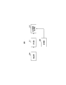
- FIG. 13 is a view for explaining the notification timing of the error detection result for the downlink data of the SCell according to the first embodiment.
- FIG. 13A is an example in which Config 1 is set in PCell and Config 3 is set in SCell, as in FIG. 8A.
- the examples of FIGS. 13B, 13C, and 13D are examples in which Config 0, Config 4, and ConfigPC2 are sequentially set in the PCell, and the same Config 3 as that in FIG. 13A is set in the SCell.
- terminal 200 focusing on subframe # 0, terminal 200 notifies an error detection result for downlink data received by SCell in a subframe of the earliest timing among subframes determined for notification.
- terminal 200 requires at least 4 ms (time required for generating a response signal including an error detection result) from receiving downlink data to notifying the error detection result. Therefore, terminal 200 notifies an error detection result for the downlink data in subframe # 2 or subframe # 7 with the earliest timing after 4 ms from the reception of downlink data. That is, as shown in FIG. 13A, FIG. 13B, or FIG. 13D, when the UL-DL Configuration having a 5 ms period is set in PCell, terminal 200 notifies an error detection result in subframe # 7 that appears next. When UL-DL configuration with a 10 ms cycle is set in PCell as shown in FIG. 13C, terminal 200 uses subframe # 12 (subframe # 2 of the next frame) at the earliest timing after 4 ms from reception. Notify the error detection result.
- terminal 200 limits the timing of notifying the error detection result in PCell to subframe # 2 or subframe # 7.
- the notification timing is the subframe # 2 or the subframe #. It is limited to 7. That is, the notification timing of the error detection result is not complicatedly distributed depending on conditions. Therefore, the base station 100 and the terminal 200 can perform processing related to the error detection result in a simplified manner. In addition, the number of test cases in the development stage of the base station 100 and the terminal 200 is reduced.
- FIG. 14 shows a data table representing the error detection result notification timing according to the combination of the UL-DL configuration of two cells (PCell and SCell) and the subframe number for receiving downlink data in the first embodiment. Indicates.
- FIG. 14 shows the error detection result for downlink data received in a certain downlink subframe of the SCell in any subframe of the PCell when a certain UL-DL configuration is set in the SCell, as in FIG. Indicates whether to notify.
- the notification timing when the same UL-DL configuration is set in two cells is indicated by hatching.
- the notification timing of the error detection result for the received data in SCell subframe # 0 is subframe # 7 when the PCell is a UL-DL configuration with a 5 ms period.
- the PCell is a UL-DL configuration with a 10 ms period, it is subframe # 12 (that is, subframe # 2 of the next frame).
- the notification timing of the error detection result for the received data in the sub-frame # 9 of the SCell is sub-frame # 17 (that is, sub-frame # 7 of the next frame) when the PCell is UL-DL configuration with a 5 ms cycle.
- the PCell is a UL-DL configuration with a 10 ms cycle, it is subframe # 22 (that is, subframe # 2 of the second frame ahead).
- the error detection result for the received data in the sub-frame # 5 of the SCell is sub-frame # 12 (that is, sub-frame # 2 of the next frame) when the PCell has a UL-DL configuration with a 5 ms cycle.
- the case where the PCell is a UL-DL configuration with a 10 ms cycle is also subframe # 12 (that is, subframe # 2 of the next frame).
- FIG. 15 is a flowchart illustrating a method for determining the notification timing of the error detection result according to the first embodiment. This determination flow is based on the premise that different UL-DL configurations are set for PCell and SCell.
- the notification timing of the error detection result (ACK / NACK) according to the first embodiment described above can be obtained by the decision flow of FIG. That is, when determining the notification timing, first, it is determined whether the UL-DL configuration of the PCell is a 10 ms cycle (a minimum cycle in which a Special subframe appears periodically) or a 5 ms cycle (S100). If the discrimination result is a 10 ms cycle, the notification timing is determined to be the earliest subframe (SF) # 2 of PCell (S101).
- the subframe number of the PDSCH in which the downlink data of the SCell is transmitted is determined (S101). As a result, if the subframe number is “# 0 to # 2, # 9”, the notification timing is determined to be the subframe # 7 with the earliest PCell (S103). If the subframe number is “# 4 to # 8”, the notification timing is determined to be subframe # 2 with the earliest PCell (S101).
- the terminal 200 adopts the error detection result notification timing defined in the case of 1CC.
- control unit 208 (see FIG. 10) of the terminal 200 may determine the notification timing of the error detection result by executing the determination flow of FIG.
- control unit 208 of the terminal 200 holds the table data indicating the notification timing determined by the determination flow of FIG. 15 in the memory, and the control unit 208 reads this table data and determines the notification timing of the error detection result. May be.
- the transmission / reception method of the first embodiment attention is paid to the following situation and timing. That is, attention is paid to the timing when 4 ms necessary for generating an error detection result of the downlink data has elapsed after the terminal 200 receives downlink data in the SCell after different UL-DL configurations are set in the PCell and the SCell. At this time, when the SCell is the UL subframe and the PCell is the DL subframe, the terminal 200 cannot notify the error detection result by the PCell at the same timing as in the case of the 1CC-SCell configuration setting. However, even in such a case, the control unit 208 of the terminal 200 according to the first embodiment can easily determine the notification timing of the error detection result for the downlink data.
- terminal 200 determines the period of the subframe number shared by a plurality of UL-DL configurations, that is, the next subframe # 2 of the PCell (in the case of UL-DL configuration with a 5 m period, the next subframe # 2 or # 7) is notified of the error detection result. Therefore, the error detection result transmission process in terminal 200 and the error detection result reception process in base station 100 are simplified.
- terminal 200 notifies PCell of an error detection result for downlink data received in the SCell unit band at the next timing. That is, if the PCell subframe is a UL subframe during the period of notification timing when 1CC-SCell configuration is set for downlink data of SCell, terminal 200 notifies the error detection result in this UL subframe. To do. If the PCell subframe in the period corresponding to the notification timing is the 1CC-SCell configuration setting, the terminal 200 notifies the error detection result at the same timing as in the first embodiment.
- the terminal 200 if the UL-DL Configuration with a 10 m period is set in the PCell, the terminal 200 notifies the error detection result in subframe # 2 that appears earliest next. Also, if a 5-m-cycle UL-DL Configuration is set in the PCell, the terminal 200 notifies the error detection result in subframe # 2 or # 7 that appears first.
- subframe # 3 of Config 0, Config 1, Config 3, Config 4, and Config 6 is a UL subframe. Therefore, when these UL-DL configurations are set in the SCell and PCell, the following can be said. That is, in this case, if the CC configuration is 1CC-SCell configuration, terminal 200 can notify the error detection result by PCell at the notification timing for the downlink data of SCell in which subframe # 3 is the notification timing.
- the terminal 200 can notify the error detection result for the downlink data received by the SCell using the PCell using the notification timing in the case of 1CC. Further, such notification timing is a common timing for a plurality of UL-DL configurations, and the notification timing is not scattered in a complicated manner by a combination of UL-DL configurations. Therefore, in such a case, it is less necessary to make the notification timing of the error detection result different from the notification timing when the 1CC-SCell configuration is set.
- FIG. 16 shows the notification timing of the error detection result according to the combination of the UL-DL configuration of two cells (PCell and SCell) and the subframe number for receiving downlink data in SCell in the second embodiment.
- a data table is shown.
- FIG. 16 shows error detection results for downlink data received in a certain downlink frame of the SCell when a certain UL-DL configuration is set in the SCell, as in FIG. 9 or FIG. , Which subframe of PCell is used for notification.
- the notification timing when the same UL-DL configuration is set in two cells is indicated by hatching, and the notification timing that is the same as that in the case of 1CC-SCell configuration setting is shown. Indicated by dot shading.
- the notification timing of the error detection result in the first and second embodiments is that the PCell UL-DL configuration is # 0 or # 6, and the SCell downlink data is received. This is different when the subframe is # 7, # 8 or # 9.
- the notification timing of Embodiment 1 is subframes # 12 and # 17, but the notification timing of Embodiment 2 is subframes # 13 and # 14.
- the notification timings of the subframes # 13 and # 14 are the same as the notification timing when the UL-DL configuration of the PCell and the UL-DL configuration of the SCell are the same.
- FIG. 17 is a flowchart illustrating a method for determining the error detection result notification timing according to the second embodiment. This determination flow is based on the premise that different UL-DL configurations are set for PCell and SCell.
- determining the notification timing first, with respect to the error detection result for the downlink data of the SCell, whether or not the PCell is a UL subframe (UL SF) during the period of the notification timing if the 1CC-SCell configuration is set. Is discriminated (S200). As a result of this determination, if it is a UL subframe, the notification timing of the error detection result is determined as this UL subframe of the PCell (S201).
- the notification timing of the error detection result is determined according to the determination method of FIG. 15 (S202).
- the notification timing of the error detection result (ACK / NACK) according to the second embodiment shown in FIG. 16 is obtained by this decision flow.
- control unit 208 (see FIG. 10) of the terminal 200 may determine the notification timing of the error detection result by executing the determination flow of FIG.
- control unit 208 of the terminal 200 holds the table data indicating the notification timing determined by the determination flow of FIG. 17 in the memory, and the control unit 208 reads this table data and determines the notification timing of the error detection result. May be.
- the terminal 200 when different UL-DL configurations are set for the PCell and the SCell, the terminal 200 notifies the PCell of an error detection result for the downlink data of the SCell.
- the notification timing of the error detection result in the PCell is determined according to the combination of the UL-DL configuration number set in the PCell and the SCell and the number of the subframe in which downlink data is received in the SCell. .
- the notification timing in the PCell of the error detection result is limited to subframe # 2 or subframe # 7 when the above combination is a partial combination.
- the error detection result transmission process in terminal 200 and the error detection result reception process in base station 100 are the same as those in the case of 1CC-SCell configuration setting or 2CC-same configuration setting. Thereby, the test cases in the development stage of the terminal 200 and the base station 100 are reduced.
- terminal 200 of Embodiment 3 In the case of 2CC-same configuration setting, terminal 200 of Embodiment 3 always shows an error detection result for downlink data received in the SCell unit band, regardless of whether uplink data (PUSCH) is transmitted in the SCell unit band. Notification by PCell. Specifically, terminal 200 reports this error detection result in the PCSCH PUSCH region or PUCCH region. Also, in the case of 2CC-specific configuration setting, the terminal 200 always notifies the PCell of the error detection result for the downlink data received in the SCell unit band regardless of whether uplink data (PUSCH) is transmitted in the SCell unit band. To do.
- the notification timing of the error detection result for the downlink data received by the SCell in the case of 2CC-specific configuration setting, and the notification timing of this error detection result in the case of the 1CC-SCell configuration setting Is different from the timing.
- the notification timing of the error detection result for the data received by the terminal 200 in the SCell unit band is different between the 2CC-same configuration setting and the 2CC-different configuration setting.
- the same UL-DL configuration is set for the PCell unit band and the SCell unit band for the terminal.
- a terminal notifies the error detection result with respect to the downlink data received by PCell, and the error detection result with respect to the downlink data received by SCell in the uplink control channel (PUCCH) area
- the terminal transmits uplink data using the SCell, the terminal notifies the error detection result as follows. That is, the terminal adds the error detection result of the downlink data previously received by the PCell and the error detection result of the downlink data previously received by the SCell to the uplink data channel of the SCell in accordance with the uplink data of the SCell. Notification is made in the (PUSCH) area.
- Such transmission on a single channel is performed in order to maintain low PAPR (Peak-to-Average Power Ratio) single carrier characteristics in uplink transmission.
- PAPR Peak-to-Average Power Ratio
- FIG. 18 shows a method (a) according to the third embodiment and a method (b) similar to LTE-Advanced Release 10 regarding the notification timing of the error detection result according to the presence / absence of uplink data transmission in the SCell.
- the explanatory view which contrasted is shown.
- FIG. 18 shows a case where different UL-DL configurations are set for the PCell unit band and the SCell unit band. However, when the same UL-DL configuration is set for them, the same contents are obtained.
- the line (A) in FIG. 18 shows a case where there is no SCell UL grant (control information for allocating resources for uplink data to a UL subframe designated by the SCell for the terminal), that is, there is no uplink data transmission. Show.
- the row (B) shows a case where there is a UL cell grant of SCell, that is, there is uplink data transmission.
- base station 100 notifies DL 200 assignment of SCell (control information for assigning downlink data resources) to terminal 200 in subframe # 0, and terminal 200 receives downlink data in this subframe. .
- the terminal 200 since the UL cell grant of the SCell is not notified, the terminal 200 notifies the error detection result for the downlink data received in the SCell subframe # 0 in the PCell subframe # 7.
- the terminal 200 When notifying the error detection result, if the uplink data resource allocation is performed for the PCell, the terminal 200 notifies the error detection result in the PUell region of the PCell.
- terminal 200 notifies the error detection result in the PUCCH region of PCell.
- base station 100 notifies terminal 200 of the UL cell grant of SCell in subframe # 0, and uses the resources in the PUSCH area of subframe # 4 of SCell for uplink data transmission. Assigned to the terminal 200.
- the terminal in a method similar to (b) LTE-Advanced Release 10, the terminal notifies an error detection result for downlink data received in SCell subframe # 0 in the PUSCH region of SCell subframe # 4.
- the base station 100 cannot recognize whether the DL assignment and UL grant notified to the terminal are correctly received by the terminal. Therefore, the base station 100 must also consider the case where the terminal fails to receive the DL assignment and UL grant.
- the base station 100 determines whether the error detection result for the downlink data received in the SCell subframe # 0 is notified in the following 1, 2 or 3 It is necessary to confirm. 1, PUSCH region of subframe # 4 shown in (B)-(b), 2, PUCCH region of PCell subframe # 7 shown in (A)-(b), 3, (A)-(b PCSCH subframe # 7 PUSCH region shown in FIG.
- the base station 100 needs to confirm the error detection result for certain downlink data across a plurality of unit bands and a plurality of timings. Therefore, the decoding process of the error detection result in the base station 100 becomes complicated.
- terminal 200 always keeps PCell even when UL grant is notified by SCell and uplink data is transmitted in the PUSCH region of SCell.
- the error detection result of SCell is notified.
- FIGS. 18B to 18A show specific examples of this notification. That is, base station 200 notifies terminal 100 of the UL cell grant of SCell in subframe # 0, and terminal 100 transmits uplink data in the PUSCH region of subframe # 4 of SCell. Even in this case, terminal 200 notifies PCell subframe # 7 of the error detection result for the downlink data received in SCell subframe # 0.
- terminal 200 always transmits an error detection result for downlink data received by SCell in the PUCCH PUCCH region or PUSCH region regardless of the presence or absence of the SCell PUSCH region. .
- base station 100 should just confirm whether the error detection result with respect to the downlink data transmitted by SCell is notified by the PUCCH area
- the notification timing of the error detection result of the SCell differs between the case of 2CC-same configuration setting and the case of 2CC-specific configuration setting, but the base station 100 determines the error detection result. Can be easily performed.
- the transmission / reception method of the third embodiment is not applicable only to the configuration of the first or second embodiment. That is, the notification timing of the error detection result for the downlink data of the SCell is not limited to application to different configurations in the case of 2CC-same configuration setting and in the case of 2CC-separate configuration setting.
- the transmission / reception method of the third embodiment is that the terminal 200 notifies the error detection result of the SCell by the PCell even when UL grant is notified by the SCell and uplink data is transmitted in the PUSCH region of the SCell. It points to the method of doing.
- the terminal 200 displays the SCell error detection result in the earliest PCell UL subframe that can be notified.
- the configuration for notification For example, for the downlink data received in SCell subframe # 9 in which Config-3 (see FIG. 3) is set, terminal 200 uses subframe # 4 in the next frame in the case of 2CC-same configuration setting. Notify the error detection result.
- the SCell when notifying the error detection result for the downlink data received by the SCell at the earliest timing of the PCell as shown in FIG.
- the terminal 200 displays the error detection result for the downlink data as a subframe of the next frame. Notification is made at # 3. If the method of Embodiment 3 is applied to the case of FIG. 7B, the following is obtained. That is, in FIG. 7B, even when PUSCH transmission is performed in subframe # 4 of the next frame of SCell, terminal 200 indicates the error detection result for the downlink data received in subframe # 9 of SCell, Notification is made in subframe # 3. Accordingly, the base station 100 does not need to determine the error detection result across a plurality of unit bands and a plurality of timings, and the base station 100 can easily perform the error detection result decoding process.
- the transmission / reception method of the third embodiment is not only applicable to the configuration of FIG. 7B and FIG. 8, the configuration of the first embodiment shown in FIG. 14, and the configuration of the second embodiment.
- the method of the third embodiment is applicable to any configuration in which the error detection result notification timing for the downlink data of the SCell is different between the 2CC-specific configuration setting and the 2CC-same configuration setting. can do. And the same effect is show
- Embodiment 4 In addition to the method of Embodiment 1 and Embodiment 2, the transmission / reception method according to Embodiment 4 adds a restriction to the subframe in which base station 100 notifies terminal 200 of DL assignment, The delay is reduced.
- FIG. 19 is a main configuration diagram of base station 100 according to Embodiment 4.
- the base station 100 includes a control unit 101 that determines assignment of downlink data resources to the terminal 200, a control information generation unit 102 that generates control information including DL assignment based on the determination of the control unit 101, and a downlink to the terminal 200.
- the wireless transmission part 111 etc. which transmit data and control information are provided.
- FIG. 20 is a diagram for explaining the delay of the error detection result according to the embodiment of the present invention.
- the notification timing of the error detection result for the downlink data of the SCell is shifted so as to be different from the notification timing in the case of 1CC-SCell configuration setting. Therefore, the delay of the error detection result may be larger than in the case of 1CC-SCell configuration setting.
- the delay of the notification timing (delay from the notification timing in the case of 1CC-SCell configuration setting) is a maximum of 4 ms when the UL-DL configuration with a period of 5 ms is set in the PCell. That is, as shown in FIG.
- terminal 200 notifies the error detection result notified in subframe # 3 in subframe # 7 if the 1CC-SCell configuration is set. Further, when the UL-DL configuration with a 10 ms period is set in the PCell, the delay of the error detection result is 9 ms at the maximum. That is, terminal 200 notifies the error detection result notified in subframe # 3 in subframe # 2 of the next frame if 1CC-SCell configuration is set.
- the base station 100 defines the delay of the error detection result notification timing (delay from the notification timing of the 1CC-SCell configuration setting) within a maximum value (for example, 4 ms). Then, base station 100 restricts subframes for transmitting downlink data to terminal 200, that is, subframes for reporting DL assignment, so that notification of an error detection result exceeding this maximum value does not occur. Specifically, when transmitting downlink data, the base station 100 prohibits notification of DL assignment for subframes in which the error detection result exceeds the maximum value. Thereby, the base station 100 can limit the delay of the error detection result within the maximum value.
- a maximum value for example, 4 ms
- the base station 100 or the terminal 200 may limit the UL-DL-Configuration that can be set in the PCell to only the UL-DL Configuration (Config 0, 1, 2, and 6) with a period of 5 ms. Also in this method, the terminal 200 can limit the delay in notification timing of the error detection result to the maximum value (4 ms) or less.
- the base station 100 may affect other terminals in the PCell. That is, when a terminal that does not support setting different UL-DL configurations in a plurality of unit bands exists in the PCell, if the UL-DL configuration of the PCell is limited, the terminal is connected to the UL-DL with a 10 ms period. Cannot communicate with DL Configuration. On the other hand, the effect of not affecting other terminals in the PCell is achieved by adopting a configuration in which the base station 100 restricts the subframes in which the DL assignment is notified as in the fourth embodiment.
- the present invention is not limited to this.
- the present invention can also be applied to the case where a TDD band is set in PCell and at least a downlink FDD band is set in SCell.
- LSI Large Scale Integration
- IC Integrated Circuit
- system LSI super LSI
- ultra LSI ultra LSI depending on the degree of integration.
- the method of circuit integration is not limited to LSI's, and implementation using dedicated circuitry or general purpose processors is also possible.
- An FPGA Field Programmable Gate Array
- a reconfigurable processor that can reconfigure the connection or setting of circuit cells inside the LSI may be used.
- integrated circuit technology comes out to replace LSI's as a result of the advancement of semiconductor technology or a derivative other technology, it is naturally also possible to carry out function block integration using this technology. For example, biotechnology can be applied.
- Each functional block used in the description of each embodiment of the present invention described above can also be realized by software that functions when a computer executes a program, or by cooperation between software and hardware.
- the present invention is useful for mobile communication systems and the like.
Abstract
複数の単位バンドに異なるUL-DL Configurationが設定される場合でも、SCellの誤り検出結果の通知タイミングが複雑に散らばらないようにして、誤り検出結果に関する処理を簡略化すること。制御部208は、第2の単位バンドの下りデータに対する応答信号の基準の通知タイミングに、第2の単位バンドのサブフレームが上り通信サブフレームであり、且つ、第1の単位バンドのサブフレームが下り通信サブフレームである場合、この下りデータに対する応答信号を、第1の単位バンドに設定された特定の上り通信サブフレーム(例えば#2又は#7)で送信する。
Description
本発明は、端末装置、基地局装置及び送受信方法に関する。
3GPP LTEでは、下り回線の通信方式としてOFDMA(Orthogonal Frequency Division Multiple Access)が採用されている。3GPP LTEが適用された無線通信システムでは、基地局が予め定められた通信リソースを用いて同期信号(Synchronization Channel:SCH)及び報知信号(Broadcast Channel:BCH)を送信する。そして、端末は、まず、SCHを捕まえることによって基地局との同期を確保する。その後、端末は、BCH情報を読むことにより基地局独自のパラメータ(例えば、周波数帯域幅など)を取得する(非特許文献1、2、3参照)。
また、端末は、基地局独自のパラメータの取得が完了した後、基地局に対して接続要求を行うことにより、基地局との通信を確立する。基地局は、通信が確立された端末に対して、必要に応じてPDCCH(Physical Downlink Control Channel)等の下り回線制御チャネルを介して制御情報を送信する。
そして、端末は、受信したPDCCH信号に含まれる複数の制御情報(下り割当制御情報:DL assignment(Downlink Control Information:DCIと呼ばれることもある))をそれぞれ「ブラインド判定」する。すなわち、制御情報は、CRC(Cyclic Redundancy Check)部分を含み、このCRC部分は、基地局において、送信対象端末の端末IDによってマスクされる。従って、端末は、受信した制御情報のCRC部分を自機の端末IDでデマスクしてみるまでは、自機宛の制御情報であるか否かを判定できない。このブラインド判定では、デマスクした結果、CRC演算がOKとなれば、その制御情報が自機宛であると判定される。
また、3GPP LTEでは、基地局から端末への下り回線データに対してARQ(Automatic Repeat Request)が適用される。つまり、端末は下り回線データの誤り検出結果を示す応答信号を基地局へフィードバックする。端末は下り回線データに対しCRCを行って、CRC=OK(誤り無し)であればACK(Acknowledgment)を、CRC=NG(誤り有り)であればNACK(Negative Acknowledgment)を応答信号として基地局へフィードバックする。この応答信号(つまり、ACK/NACK信号。以下、単に「A/N」と表記することもある)のフィードバックには、PUCCH(Physical Uplink Control Channel)等の上り回線制御チャネルが用いられる。
ここで、基地局から送信される上記制御情報には、基地局が端末に対して割り当てたリソース情報等を含むリソース割当情報が含まれる。この制御情報の送信には、前述の通りPDCCHが用いられる。このPDCCHは、1つ又は複数のL1/L2CCH(L1/L2 Control Channel)から構成される。各L1/L2CCHは、1つ又は複数のCCE(Control Channel Element)から構成される。すなわち、CCEは、制御情報をPDCCHにマッピングするときの基本単位である。また、1つのL1/L2CCHが複数(2,4,8個)のCCEから構成される場合には、そのL1/L2CCHには偶数のインデックスを持つCCEを起点とする連続する複数のCCEが割り当てられる。基地局は、リソース割当対象端末に対する制御情報の通知に必要なCCE数に従って、そのリソース割当対象端末に対してL1/L2CCHを割り当てる。そして、基地局は、このL1/L2CCHのCCEに対応する物理リソースにマッピングして制御情報を送信する。
また、ここで、各CCEは、PUCCHの構成リソース(以下、PUCCHリソースと呼ぶことがある)と1対1に対応付けられている。従って、L1/L2CCHを受信した端末は、このL1/L2CCHを構成するCCEに対応するPUCCHの構成リソースを特定し、このリソースを用いて応答信号を基地局へ送信する。ただし、L1/L2CCHが連続する複数のCCEを占有する場合には、端末は、複数のCCEにそれぞれ対応する複数のPUCCH構成リソースのうち一番インデックスが小さいCCEに対応するPUCCH構成リソース(すなわち、偶数番号のCCEインデックスを持つCCEに対応付けられたPUCCH構成リソース)を利用して、応答信号を基地局へ送信する。こうして下り回線の通信リソースが効率良く使用される。
複数の端末から送信される複数の応答信号は、図1に示すように、時間軸上でZero Auto-correlation特性を持つZAC(Zero Auto-correlation)系列、ウォルシュ(Walsh)系列、及び、DFT(Discrete Fourier Transform)系列によって拡散され、PUCCH内でコード多重されている。図1において(W0,W1,W2,W3)は系列長4のウォルシュ系列を表し、(F0,F1,F2)は系列長3のDFT系列を表す。図1に示すように、端末では、ACK又はNACKの応答信号が、まず周波数軸上でZAC系列(系列長12)によって1SC-FDMAシンボルに対応する周波数成分へ1次拡散される。すなわち、系列長12のZAC系列に対して複素数で表される応答信号成分が乗算される。次いで1次拡散後の応答信号及び参照信号としてのZAC系列がウォルシュ系列(系列長4:W0~W3。ウォルシュ符号系列(Walsh Code Sequence)と呼ばれることもある)、DFT系列(系列長3:F0~F3)それぞれに対応させられて2次拡散される。すなわち、系列長12の信号(1次拡散後の応答信号、又は、参照信号としてのZAC系列(Reference Signal Sequence)のそれぞれの成分に対して、直交符号系列(Orthogonal sequence:ウォルシュ系列又はDFT系列)の各成分が乗算される。さらに、2次拡散された信号が、IFFT(Inverse Fast Fourier Transform)によって時間軸上の系列長12の信号に変換される。そして、IFFT後の信号それぞれに対しCPが付加され、7つのSC-FDMAシンボルからなる1スロットの信号が形成される。
異なる端末からの応答信号同士は、異なる巡回シフト量(Cyclic Shift Index)に対応するZAC系列、又は、異なる系列番号(Orthogonal Cover Index : OC index)に対応する直交符号系列を用いて拡散されている。直交符号系列は、ウォルシュ系列とDFT系列との組である。また、直交符号系列はブロックワイズ拡散コード系列(Block-wise spreading code)と称されることもある。従って、基地局は、従来の逆拡散及び相関処理を用いることにより、これらコード多重された複数の応答信号を分離することができる(非特許文献4参照)。
ただし、各端末が各サブフレームにおいて自分宛の下り割当制御信号をブラインド判定するので、端末側では、必ずしも下り割当制御信号の受信が成功するとは限らない。端末が或る下り単位バンドにおける自分宛の下り割当制御信号の受信に失敗した場合、端末は、当該下り単位バンドにおいて自分宛の下り回線データが存在するか否かさえも知り得ない。従って、或る下り単位バンドにおける下り割当制御信号の受信に失敗した場合、端末は、当該下り単位バンドにおける下り回線データに対する応答信号も生成しない。このエラーケースは、端末側で応答信号の送信が行われないという意味での、応答信号のDTX(DTX (Discontinuous transmission) of ACK/NACK signals)として定義されている。
ところで、3GPP LTEシステム(以下、「LTEシステム」と呼ばれることがある)では、基地局は上り回線データ及び下り回線データに対してそれぞれ独立にリソース割当を行う。そのため、LTEシステムでは、上り回線において、端末(つまり、LTEシステム対応の端末(以下、「LTE端末」と呼ぶ))が、下り回線データに対する応答信号と、上り回線データとを同時に送信しなければならない状況が発生する。この状況では、端末からの応答信号及び上り回線データは、時間多重(Time Division Multiplexing:TDM)を用いて送信される。このように、TDMを用いて応答信号と上り回線データとを同時に送信することで、端末の送信波形のシングルキャリア特性(Single carrier properties)を維持している。
また、図2に示すように、時間多重(TDM)では、端末から送信される応答信号(「A/N」)は、上り回線データ向けに割り当てられたリソース(PUSCH(Physical Uplink Shared CHannel)リソース)の一部(参照信号(RS:Reference Signal)がマッピングされるSC-FDMAシンボルに隣接するSC-FDMAシンボルの一部)を占有して基地局に送信される。ただし、図2における縦軸の「Subcarrier」は「Virtual subcarrier」、又は「Time contiguous signal」と呼ばれることもあり、SC-FDMA送信機においてDFT(Discrete Fourier Transform)回路に纏めて入力される「時間的に連続する信号」を便宜上「subcarrier」として表したものである。すなわち、PUSCHリソースでは、応答信号によって、上り回線データのうちの任意のデータがパンクチャ(puncture)される。このため、符号化後の上り回線データの任意のビットがパンクチャされることで、上り回線データの品質(例えば、符号化利得)が大幅に劣化する。そのため、基地局は、例えば、端末に対して非常に低い符号化率を指示したり、非常に大きな送信電力を指示したりすることで、パンクチャによる上り回線データの品質劣化を補償する。
また、3GPP LTEよりも更なる通信の高速化を実現する3GPP LTE-Advancedの標準化が行われている。3GPP LTE-Advancedシステム(以下、「LTE-Aシステム」と呼ばれることがある)は、LTEシステムを踏襲する。3GPP LTE-Advancedでは、最大1Gbps以上の下り伝送速度を実現するために、40MHz以上の広帯域周波数で通信可能な基地局及び端末が導入される。
LTE-Aシステムにおいては、LTEシステムにおける伝送速度の数倍もの超高速伝送速度による通信、及び、LTEシステムに対する後方互換性(バックワードコンパチビリティー:Backward Compatibility)を同時に実現するために、LTE-Aシステム向けの帯域が、LTEシステムのサポート帯域幅である20MHz以下の「単位バンド」に区切られる。すなわち、「単位バンド」は、ここでは、最大20MHzの幅を持つ帯域であって、通信帯域の基本単位として定義される。FDD(Frequency Division Duplex)システムでは、さらに、下り回線における「単位バンド」(以下、「下り単位バンド」と呼ぶ)は基地局から報知されるBCHの中の下り周波数帯域情報によって区切られた帯域、又は、下り制御チャネル(PDCCH)が周波数領域に分散配置される場合の分散幅によって定義される帯域として定義されることもある。また、上り回線における「単位バンド」(以下、「上り単位バンド」と呼ぶ)は、基地局から報知されるBCHの中の上り周波数帯域情報によって区切られた帯域、又は、中心付近にPUSCH(Physical Uplink Shared Channel)領域を含み、両端部にLTE向けのPUCCHを含む20MHz以下の通信帯域の基本単位として定義されることもある。なお、「単位バンド」は、3GPP LTE-Advancedにおいて、英語でComponent Carrier(s)又はCellと表記されることがある。また、略称としてCC(s)と表記されることもある。
TDD(Time Division Duplex)システムでは、下り単位バンドと上り単位バンドとが同一周波数帯域であり、時分割で下り回線と上り回線とを切り替えることによって、下り通信と上り通信とを実現する。そのためTDDシステムの場合、下り単位バンドは、「単位バンドにおける下り通信タイミング」とも表現できる。上り単位バンドは、「単位バンドにおける上り通信タイミング」とも表現できる。下り単位バンドと上り単位バンドとの切り替えは、図3に示すように、UL-DL Configurationに基づく。図3に示すUL-DL Configurationでは、1フレーム(10msec)当たりの下り通信(DL:Downlink)と上り通信(UL:Uplink)とのサブフレーム単位(すなわち、1msec単位)のタイミングが設定される。UL-DL Configurationは、下り通信と上り通信とのサブフレーム割合を変更することにより、下り通信に対するスループット及び上り通信に対するスループットの要求に柔軟に対応できる通信システムを構築することができる。例えば、図3は、下り通信と上り通信とのサブフレーム割合が異なるUL-DL Configuration(Config 0~6)を示す。また、図3において、下り通信サブフレームを「D」で表し、上り通信サブフレームを「U」で表し、スペシャルサブフレームを「S」で表す。ここで、スペシャルサブフレームは、下り通信サブフレームから上り通信サブフレームへの切替時のサブフレームである。また、スペシャルサブフレームでは、下り通信サブフレームと同様、下りデータ通信が行われる場合がある。なお、図3に示す各UL-DL Configurationでは、2フレーム分のサブフレーム(20サブフレーム)を、下り通信に用いられるサブフレーム(上段の「D」及び「S」)と上り通信に用いられるサブフレーム(下段の「U」)とに分けて2段で表している。また、図3に示すように、下りデータに対する誤り検出結果(ACK/NACK)は、当該下りデータが割り当てられたサブフレームの4サブフレーム以上後の上り通信サブフレームで通知される。
LTE-Aシステムでは、単位バンドを幾つか束ねた帯域を用いた通信、所謂Carrier aggregation(CA)がサポートされる。なお、UL-DL Configurationは、単位バンド毎に設定可能であるが、LTE-Aシステム対応の端末(以下、「LTE-A端末」と呼ぶ)は、複数の単位バンド間で同じUL-DL Configurationが設定されることを想定して設計されている。
図4は、個別の端末に適用される非対称のCarrier aggregation及びその制御シーケンスの説明に供する図である。
図4Bに示すように、端末1に対しては、2つの下り単位バンドと左側の1つの上り単位バンドを用いてCarrier aggregationを行うような設定(Configuration)が為される。一方、端末2に対しては、端末1と同一の2つの下り単位バンドを用いるような設定が為されるにも拘らず、上り通信では右側の上り単位バンドを利用するような設定が為される。
そして、端末1に着目すると、LTE-Aシステムを構成する基地局(つまり、LTE-Aシステム対応の基地局(以下、「LTE-A基地局」と呼ぶ))とLTE-A端末との間では、図4Aに示すシーケンス図に従って、信号の送受信が行われる。図4Aに示すように、(1)端末1は、基地局との通信開始時に、左側の下り単位バンドと同期を取り、左側の下り単位バンドとペアになっている上り単位バンドの情報をSIB2(System Information Block Type 2)と呼ばれる報知信号から読み取る。(2)端末1は、この上り単位バンドを用いて、例えば、接続要求を基地局に送信することによって基地局との通信を開始する。(3)端末に対し複数の下り単位バンドを割り当てる必要があると判断した場合には、基地局は、端末に下り単位バンドの追加を指示する。ただし、この場合、上り単位バンド数は増えず、個別の端末である端末1において非対称Carrier aggregationが開始される。
また、前述のCarrier aggregationが適用されるLTE-Aでは、端末が一度に複数の下り単位バンドにおいて複数の下り回線データを受信することがある。LTE-Aでは、この複数の下り回線データに対する複数の応答信号の送信方法として、Channel Selection(Multiplexingとも呼ぶ)、Bundling、及び、DFT-S-OFDM(Discrete Fourier Transform spread Orthogonal Frequency Division Multiplexing)フォーマットがある。Channel Selectionでは、端末は、複数の下り回線データに関する誤り検出結果のパターンに応じて、応答信号に用いるシンボル点だけでなく、応答信号をマッピングするリソースも変化させる。これに対し、Bundlingでは、端末は、複数の下り回線データに関する誤り検出結果より生成されたACK又はNACK信号をBundlingして(すなわち、ACK=1、NACK=0とし、複数の下り回線データに関する誤り検出結果の論理積(Logical AND)を計算して)、予め決められた一つのリソースを用いて応答信号を送信する。また、DFT-S-OFDMフォーマットを用いた送信時には、端末は、複数の下り回線データに対する応答信号を纏めて符号化(Joint coding)し、当該フォーマットを用いてその符号化データを送信する(非特許文献5参照)。例えば、端末は、誤り検出結果のパターンのビット数に応じて、Channel Selection、Bundling、又は、DFT-S-OFDMのいずれかによる応答信号(ACK/NACK)のフィードバックを行ってもよい。又は、基地局が上記応答信号の送信方法を予め設定してもよい。
Channel Selectionは、図5に示すように、複数の下り単位バンド(最大2つの下り単位バンド)で受信した、下り単位バンド毎の複数の下り回線データに対する誤り検出結果がそれぞれACKかNACKかに基づいて、応答信号の位相点(すなわち、Constellation point)だけではなく、応答信号の送信に用いるリソース(以下、「PUCCHリソース」と表記することもある)も変化させる手法である。これに対し、Bundlingは、複数の下り回線データに対するACK/NACK信号を一つに束ねて、予め決められた一つのリソースから送信する手法である(非特許文献6、7参照)。以下、複数の下り回線データに対するACK/NACK信号を一つに束ねた信号を束ACK/NACK信号と呼ぶことがある。
ここで、端末がPDCCHを介して下り割当制御情報を受信し、下り回線データを受信した場合における上り回線での応答信号の送信方法として、以下の2つの方法が考えられる。
一つは、PDCCHが占有しているCCE(Control Channel Element)と1対1に関連付けられたPUCCHリソースを用いて応答信号を送信する方法(Implicit signaling)である(方法1)。つまり、基地局配下の端末に向けたDCIをPDCCH領域に配置する場合、各PDCCHは、1つ又は連続する複数のCCEで構成されるリソースを占有する。また、PDCCHが占有するCCE数(CCE連結数:CCE aggregation level)としては、例えば、割当制御情報の情報ビット数又は端末の伝搬路状態に応じて、1,2,4,8の中の1つが選択される。
もう一つは、基地局からPUCCH向けのリソースを端末に対して予め通知しておく方法(Explicit signaling)である(方法2)。つまり、方法2では、端末は、基地局から予め通知されたPUCCHリソースを用いて応答信号を送信する。
また、図5に示すように、端末は、2つの単位バンドのうち、1つの単位バンドを用いて、応答信号を送信する。このような応答信号を送信する単位バンドは、PCC(Primary Component Carrier)又はPCell(Primary Cell)と呼ばれる。また、それ以外の単位バンドは、SCC(Secondary Component Carrier)又はSCell(Secondary Cell)と呼ばれる。例えば、PCC(PCell)は、応答信号を送信する単位バンドに関する報知情報(例えば、SIB2(System Information Block type2))を送信している単位バンドである。
なお、方法2では、複数の端末間で共通のPUCCH向けのリソース(例えば4つのPUCCH向けのリソース)を、基地局から端末に対して予め通知してもよい。例えば、端末は、SCell内のDCIに含まれる2ビットのTPC(Transmit Power Control)コマンド(送信電力制御命令)に基づいて、実際に用いるPUCCH向けのリソースを1つ選択する方法を採ってもよい。その際、当該TPCコマンドは、ARI(Ack/nack Resource Indicator)とも呼ばれる。これにより、Explicit signaling時に、或るサブフレームにおいて、或る端末がexplicit signalingされたPUCCH向けのリソースを使い、別のサブフレームでは、別の端末が、同一のexplicit signalingされたPUCCH向けのリソースを使うことができるようになる。
また、Channel selectionでは、PCC(PCell)内のPDSCH(Physical Downlink Shared CHannel)を指示するPDCCHが占有している、CCEの先頭CCEインデックスに1対1に関連付けられて、上り単位バンド内のPUCCHリソース(図5ではPUCCH領域1内のPUCCHリソース)が割り当てられる(Implicit signaling)。
ここで、上記した非対称のCarrier aggregationが端末に適用される場合のChannel SelectionによるARQ制御について、図5、図6を援用して説明する。
例えば、図5では、端末1に対して、単位バンド1(PCell)、単位バンド2(SCell)から成る単位バンドグループ(英語で「Component carrier set」と表記されることがある)が設定される。この場合には、単位バンド1,2のそれぞれのPDCCHを介して下りリソース割当情報が基地局から端末1へ送信された後に、その下りリソース割当情報に対応するリソースで下り回線データが送信される。
また、Channel selectionでは、単位バンド1(PCell)における複数の下りデータに対する誤り検出結果と、単位バンド2(SCell)における複数の下りデータに対する誤り検出結果とを表す応答信号が、PUCCH領域1内又はPUCCH領域2内に含まれるPUCCHリソースにマッピングされる。また、端末は、その応答信号として、2種類の位相点(BPSK(Binary Phase Shift Keying)マッピング)又は4種類の位相点(QPSK(Quadrature Phase Shift Keying)マッピング)のいずれかを用いる。すなわち、Channel selectionでは、PUCCHリソースと位相点との組み合わせにより、単位バンド1(PCell)における複数の下りデータに対する誤り検出結果、及び、単位バンド2(SCell)における複数の下りデータに対する誤り検出結果のパターンを表すことができる。
ここで、TDDシステムにおいて、単位バンドが2つの場合(PCellが1つ、SCellが1つの場合)の誤り検出結果のパターンのマッピング方法を図6Aに示す。
なお、図6Aは、送信モードが以下の(a),(b),(c)のいずれかに設定される場合を想定する。
(a)各単位バンドが、下り1CW送信のみをサポートする送信モード
(b)一方の単位バンドが、下り1CW送信のみをサポートする送信モードで、
他方の単位バンドが、下り2CW送信までをサポートする送信モード
(c)各単位バンドが、下り2CW送信までをサポートする送信モード
(a)各単位バンドが、下り1CW送信のみをサポートする送信モード
(b)一方の単位バンドが、下り1CW送信のみをサポートする送信モードで、
他方の単位バンドが、下り2CW送信までをサポートする送信モード
(c)各単位バンドが、下り2CW送信までをサポートする送信モード
更に、図6Aは、単位バンド当たりに、何個分の下り通信サブフレーム(以降、「DL(DownLink)サブフレーム」と記載する。図3に示す「D」又は「S」)の誤り検出結果を、1つの上り通信サブフレーム(以降、「UL(UpLink)サブフレーム」と記載する。図3に示す「U」)で基地局に通知する必要があるか、を表す数Mが、以下の(1)~(4)のいずれかに設定される場合を想定する。例えば、図3に示すConfig 2では、4個のDLサブフレームの誤り検出結果が1つのULサブフレームで基地局に通知されるので、M=4となる。
(1)M=1
(2)M=2
(3)M=3
(4)M=4
(1)M=1
(2)M=2
(3)M=3
(4)M=4
つまり、図6Aは、上記(a)~(c)及び上記(1)~(4)のそれぞれを組み合わせた場合の誤り検出結果のパターンのマッピング方法を示す。なお、Mの値は、図3に示すように、UL-DL Configuration(Config 0~6)、及び、1フレーム内のサブフレーム番号(SF#0~SF#9)によって異なる。また、図3に示すConfig 5では、サブフレーム(SF)#2においてM=9となる。しかし、この場合、LTE-AのTDDシステムでは、端末は、Channel selectionを適用せずに、例えばDFT-S-OFDMフォーマットを用いて誤り検出結果を通知する。このため、図6Aでは、Config 5(M=9)を、上記組合せに組み入れていない。
(1)の場合、誤り検出結果のパターン数は、(a)、(b)、(c)の順に、22×1=4パターン、23×1=8パターン、24×1=16パターン存在する。(2)の場合、誤り検出結果のパターン数は、(a)、(b)、(c)の順に、22×2=8パターン、23×2=16パターン、24×2=32パターン存在する。(3)、(4)の場合も同様である。
ここで、1つのPUCCHリソースにおいてマッピングする各位相点間の位相差が最小でも90度である場合(すなわち、1つのPUCCHリソースあたり最大4パターンをマッピングする場合)を想定する。この場合、誤り検出結果の全てのパターンをマッピングするために必要なPUCCHリソース数は、誤り検出結果のパターン数が最大の(4)かつ(c)の場合(24×4=64パターン)に、24×4÷4=16個必要になってしまい、現実的ではない。そこで、TDDシステムでは、誤り検出結果を、空間領域、さらに必要ならば、時間領域で束ねる(バンドリング:Bundling)ことで、誤り検出結果の情報量を意図的に欠落させる。これにより、誤り検出結果パターンの通知に必要なPUCCHリソース数を制限している。
LTE-AのTDDシステムでは、(1)の場合、端末は、誤り検出結果をバンドリングせずに、(a)、(b)、(c)の順に、4パターン、8パターン、16パターンの誤り検出結果パターンを、それぞれ2つ、3つ、4つのPUCCHリソースにマッピングする(図6AのStep3)。すなわち、端末は、下り回線で1CW(コードワード:codeword)送信のみをサポートする送信モード(non-MIMO)が設定された単位バンドあたり、1ビットの誤り検出結果を通知し、下り回線で2CW送信までをサポートする送信モード(MIMO)が設定された単位バンドあたり、2ビットの誤り検出結果を通知する。
LTE-AのTDDシステムでは、(2)かつ(a)の場合も、端末は、誤り検出結果をバンドリングせずに、8パターンの誤り検出結果パターンを、4つのPUCCHリソースにマッピングする(図6AのStep3)。その際、端末は、1つの下り単位バンドあたり、2ビットの誤り検出結果を通知する。
LTE-AのTDDシステムでは、(2)かつ(b)((2)かつ(c)も同様)の場合、端末は、下り回線で2CW送信までをサポートする送信モードが設定された単位バンドの誤り検出結果を空間領域でバンドリング(空間バンドリング:Spatial bundling)(図6AのStep1)する。空間バンドリングでは、たとえば、2CWの誤り検出結果のうち、少なくとも一方のCWに対する誤り検出結果がNACKである場合、空間バンドリング後の誤り検出結果をNACKと判定する。すなわち、空間バンドリングでは、2CWの誤り検出結果に対して論理AND(Logical And)をとる。そして、端末は、空間バンドリング後の誤り検出結果パターン((2)かつ(b)の場合は8パターン、(2)かつ(c)の場合は16パターン)を、4つのPUCCHリソースにマッピングする(図6AのStep3)。その際、端末は、1つの下り単位バンドあたり、2ビットの誤り検出結果を通知する。
LTE-AのTDDシステムでは、(3)又は(4)、かつ、(a)、(b)又は(c)の場合、端末は、空間バンドリング(Step1)後に、時間領域でバンドリング(時間領域バンドリング:Time-domain bundling)する(図6AのStep2)。そして、端末は、時間領域バンドリング後の誤り検出結果パターンを、4つのPUCCHリソースにマッピングする(図6AのStep3)。その際、端末は、1つの下り単位バンドあたり、2ビットの誤り検出結果を通知する。
次に、図6Bを用いて、具体的なマッピング方法の一例を示す。図6Bは、下り単位バンドが2つ(PCellが1つ、SCellが1つ)の場合、かつ、「(c)各単位バンドが、下り2CW送信までをサポートする送信モード」が設定され、かつ、「(4)M=4」の場合の例である。
図6Bでは、PCellの誤り検出結果が、4つのDLサブフレーム(SF1~4)で、(CW0,CW1)の順に、(ACK(A),ACK)、(ACK,ACK)、(NACK(N),NACK)、(ACK,ACK)となる。図6Bに示すPCellでは、M=4であるので、端末は、図6AのStep1で、これらを空間バンドリングする(図6Bの実線で囲んだ部分)。空間バンドリングの結果、図6Bに示すPCellの4つのDLサブフレームでは、順にACK、ACK、NACK、ACKが得られる。さらに、端末は、図6AのStep2で、Step1で得られた空間バンドリング後の4ビットの誤り検出結果パターン(ACK,ACK,NACK,ACK)に対して、時間領域バンドリングする(図6Bの破線で囲んだ部分)。これにより、図6Bに示すPCellでは、(NACK,ACK)の2ビットの誤り検出結果が得られる。
端末は、図6Bに示すSCellについても同様に、空間バンドリング及び時間領域バンドリングを行うことにより、(NACK,NACK)の2ビットの誤り検出結果が得られる。
そして、端末は、図6AのStep3で、PCell及びSCellの時間領域バンドリング後の各2ビットの誤り検出結果パターンをPCell、SCellの順に組み合わせて、4ビットの誤り検出結果パターン(NACK,ACK,NACK,NACK)にまとめる。端末は、この4ビットの誤り検出結果パターンを、図6AのStep3に示すマッピングテーブルを用いて、PUCCHリソース(この場合、h1)と位相点(この場合、-j)とを決定する。
3GPP TS 36.211 V10.1.0, "Physical Channels and Modulation (Release 9)," March 2011
3GPP TS 36.212 V10.1.0, "Multiplexing and channel coding (Release 9)," March 2011
3GPP TS 36.213 V10.1.0, "Physical layer procedures (Release 9)," March 2011
Seigo Nakao, Tomofumi Takata, Daichi Imamura, and Katsuhiko Hiramatsu, "Performance enhancement of E-UTRA uplink control channel in fast fading environments,"Proceeding of IEEE VTC 2009 spring, April. 2009
Ericsson and ST-Ericsson, "A/N transmission in the uplink for carrier aggregation," R1-100909, 3GPP TSG-RAN WG1 #60, Feb. 2010
ZTE, 3GPP RAN1 meeting #57, R1-091702, "Uplink Control Channel Design for LTE-Advanced," May 2009
Panasonic, 3GPP RAN1 meeting #57, R1-091744, "UL ACK/NACK transmission on PUCCH for Carrier aggregation," May 2009
LTE-A端末は、前述のとおり、複数の単位バンド間で同じUL-DL Configurationが設定されることを想定して設計されている。
ところで、LTE-AのTDDシステムを提供する通信キャリアが、周波数帯域を新たにLTE-Aサービスに割り当てる際には、次のようなUL-DL Configurationの設定を行うことが検討されている。すなわち、当該通信キャリアが、どのサービスを重視するかに応じて、新たに割り当てた周波数帯域のUL-DL Configurationを、既存の周波数帯域のUL-DL Configurationと異なる設定にする。具体的には、下り通信のスループットを重視する通信キャリアでは、新たな周波数帯域に、ULサブフレームに対するDLサブフレームの割合が大きいUL-DL Configuration(例えば図3では、Config 3、4又は5等)が用いられる。これにより、より柔軟なシステム構築が行われる。
しかしながら、単位バンド間でUL-DL Configurationが異なる場合、つまり、単位バンド間で「M」の値が異なる場合の誤り検出結果のバンドリング方法については、これまで検討されてこなかった。
図7Aおよび図7Bは、単位バンド間でUL-DL Configurationが異なる場合の誤り検出結果の通知方法の一例を示す。例えば、図7A及び図7Bでは、Config 1が設定された単位バンド(周波数f1)はPCellであり、Config 3が設定された単位バンド(周波数f2)はSCellである。
図7Aは、PCellおよびSCellのそれぞれの単位バンドで独立に誤り検出結果を通知する方法である。図7Aの方法では、端末は、単位バンド毎に独立に誤り検出結果を通知できるため、複雑度は低い。しかし、図7Aの方法では、2つの単位バンド毎に誤り検出結果(応答信号)を送信するためのリソース(A/Nリソース)が必要となる。さらに、図7Aの方法では、基地局は、2つの単位バンドの誤り検出結果に対して、復号処理を並列(つまり、2並列)で行う必要がある。つまり、図7Aの方法では、端末に1単位バンド(1CC)のみが設定される3GPP Release 10(Rel-10)と比較して、2倍のA/Nリソース及び2倍の復号処理が必要となる。
また、端末に対して単位バンドが最大5CC設定される場合、最大5CC分のA/Nリソースが必要となる。さらに、基地局においては、最大5並列(1CCの誤り検出結果/1並列)で誤り検出結果の復号処理を行うことが必要となってしまう。ここで、単位バンド間でUL-DL Configurationが常に同じである場合には各単位バンドでのULサブフレームのタイミングは同じである。よって、端末に対して単位バンドが最大5CC設定されている場合であっても、A/Nリソース量は1CC分のA/Nリソースで済む。さらに、基地局における誤り検出結果の復号処理も最大5CC設定時において1並列分(1CCの誤り検出結果に対する処理)で済む。これに対し、単位バンド間でUL-DL Configurationが異なる場合は、最大5倍のA/Nリソースおよび復号処理量を要することになる。
一方、図7Bの方法は、各単位バンドの誤り検出結果を常にPCellでまとめて通知する方法である。すなわち、図7Bの方法では、PCell及びSCellの双方の誤り検出結果は、PCellのULサブフレームで送信される。図7Bの方法では、端末は、常にPCellから誤り検出結果を通知するため、使用するA/NリソースはPCellの1CC分でよい。また、基地局における誤り検出結果の復号処理についても、1並列分でよい(最大5CCの誤り検出結果/1並列)。
しかし、PCell及びSCellにそれぞれ設定されるUL-DL Configurationの組合せに応じて、SCellの誤り検出結果の通知タイミングが、1CC時と比較して前後することがある。例えば、図7Bにおいて、Config 3が設定されたSCellのサブフレーム#0のデータの誤り検出結果に対する、最も早い通知タイミングは、PCellのサブフレーム#7である。しかし、図3に示すように、Config 3が単一の単位バンド(1CC)のみに設定されている場合、サブフレーム#0のデータに対する誤り検出結果に対する通知タイミングは、サブフレーム#4である。このように、複数のUL-DL Configurationおよびサブフレーム番号の組合せに応じて、誤り検出結果の通知タイミングが異なってしまう。この場合、基地局および端末の誤り検出結果に関する処理が非常に煩雑になり、また基地局および端末の開発段階のテストケースが増加してしまう。
処理の煩雑化に関して、図8を用いてより具体的に説明する。図8Aから図8Dには、SCellにConfig 3、PCellに異なるUL-DL Configurationがそれぞれ設定された場合の誤り検出結果(A/N)の通知タイミングを示す。図8Aから図8Dの方法では、図7Bの方法のように、端末は、SCellの下りデータに対する誤り検出結果を常にPCellで通信する。
図8Aでは、図7Bと同様、PCellにはConfig 1が設定され、SCellにはConfig 3が設定されている。図8B、図8Cおよび図8Dではそれぞれ、図8AとPCellに設定されるUL-DL Configurationが異なり、PCellには、順に、Config 0、Config 4、Config 2が設定されている。ここで、サブフレーム#0に着目して、端末が、SCellで受信した下りデータに対する誤り検出結果を、PCellの最も早いタイミングで通知することを検討する。図8Aと図8DのようにPCellがConfig 1およびConfig 2の場合には、端末はSCellのサブフレーム#0で受信した下りデータに対する誤り検出結果をサブフレーム#7で通知する。図8BのようにPCellがConfig 0の場合には、端末はSCellのサブフレーム#0で受信した下りデータに対する誤り検出結果をサブフレーム#4で通知する。図8CのようにPCellがConfig 4の場合には、端末はSCellのサブフレーム#0で受信した下りデータに対する誤り検出結果をサブフレーム#12(次フレーム(1フレームは10サブフレームから成る)のサブフレーム#2)で通知する。このように、PCellとSCellとで異なるUL-DL Configurationが設定された場合、端末は、SCellの同一のサブフレームで受信した下りデータに対する誤り検出結果をPCellの異なるタイミングで通知する。すなわち、複数のUL-DL Configurationの組合せと、SCellにおける下りデータを受信するサブフレーム番号との組合せに応じて、端末は、この下りデータに対する誤り検出結果をPCellの様々なタイミングで通知してしまう。従って、図8Aから図8Dに示す方法において、基地局および端末は、複数のUL-DL Configuration(2種類の場合は7×7=49通り)とサブフレーム番号(Config 5のとき最大9通り)との組合せに応じた誤り検出結果の通知タイミングを予め定めておかねばならない。この組合せ数は非常に多いため、基地局および端末における誤り検出結果の通知に関する処理は非常に煩雑になる。また、基地局および端末の開発段階のテストケースが増加してしまう。
図9には、2つのセル(PCellとSCell)のUL-DL Configurationと下りデータを受信するサブフレーム番号との組合せに応じた誤り検出結果の通知タイミング(PCellのどのサブフレームで通知するか)を表わしたデータテーブルを示す。図9Aから図9Gの複数のデータテーブルは、SCellのUL-DL ConfigurationがそれぞれConfig 0からConfig 6であるときのデータテーブルである。各データテーブルの複数の行には、PCellのUL-DL ConfigurationがConfig 0からConfig6の場合の通知タイミングがそれぞれ示されている。また、複数の列には、SCellのサブフレーム番号#0から#9で受信した下りデータに対する誤り検出結果である場合の通知タイミングがそれぞれ示されている。また、図9には、2つのセルに同一のUL-DL Configurationが設定されているときの通知タイミングが斜線の網掛けにより示され、UL-DL Configurationの組み合わせにより散らばった通知タイミングがドットの網掛けにより示されている。
例えば、図9Dに示されるように、SCellがConfig 3であり、PCellのUL-DL ConfigurationがSCellのUL-DL Configurationと異なる(すなわちConfig 3以外)場合には、次のようになる。すなわち、SCellのサブフレーム#0の受信データに対する誤り検出結果の通知タイミングは、PCellがConfig 0、Config 3またはConfig 6の場合、サブフレーム#4である。PCellがConfig 1またはConfig 2の場合、上記通知タイミングはサブフレーム#7である。PCellがConfig 4またはConfig 5の場合、上記通知タイミングはサブフレーム#12(すなわち次のフレーム(1フレームは10サブフレームから成る)のサブフレーム#2)である。
また、SCellのサブフレーム#9の受信データに対する誤り検出結果の通知タイミングは、PCellがConfig 0、Config 1、Config 4またはConfig 6の場合、サブフレーム#13(すなわち次フレームのサブフレーム#3)である。PCellがConfig 2の場合、上記通知タイミングはサブフレーム#17(すなわち次フレームのサブフレーム#7)である。PCellがConfig 5の場合、上記通知タイミングはサブフレーム#22(すなわち次々フレームのサブフレーム#2)である。
本発明の目的は、複数の単位バンドを使用した通信においてARQが適用される場合、かつ、単位バンド毎に設定されるUL-DL Configuration(ULサブフレームとDLサブフレームとの割合)が異なる場合において、SCellで受信した下りデータの誤り検出結果の通知タイミングが複雑に散らばらないようにすることである。そして、それにより、端末での応答信号の送信処理と基地局での応答信号の受信処理を簡略化できる端末装置、基地局装置及び送受信方法を提供することである。
本発明の一態様に係る端末装置は、第1の単位バンド(例えばPCellの単位バンド)と第2の単位バンド(例えばSCellの単位バンド)とを含む複数の単位バンドを用いて基地局装置と通信し、前記各単位バンドには1フレーム内における下り通信サブフレームおよび上り通信サブフレームを含む複数種類のサブフレームの配置を規定した構成パターンが設定される端末装置であって、前記複数の単位バンドで下りデータをそれぞれ受信する受信手段と、各下りデータの誤りを検出する誤り検出手段と、前記誤り検出手段で得られる各下りデータの誤り検出結果を示す応答信号を生成する生成手段と、前記応答信号を前記基地局装置へ送信する制御手段と、を具備し、前記第1の単位バンドと前記第2の単位バンドには異なる前記構成パターンが設定可能であり、前記制御手段は、前記第2の単位バンドで受信した下りデータに対する応答信号を前記第1の単位バンドで送信するとともに、前記第2の単位バンドで受信した下りデータに対する応答信号の基準の送信期間に、前記第1の単位バンドのサブフレームが下り通信サブフレームであり、且つ、前記第2の単位バンドのサブフレームが上り通信サブフレームである場合に、前記下りデータに対する応答信号を、前記第1の単位バンドに設定された特定の上り通信サブフレームで送信し、前記特定の上り通信サブフレームは、前記サブフレームの種類の切り替わり点が周期的に現れる最小の周期ごとに一つずつ設定され、且つ、前記最小の周期内で同一の期間に配置される上り通信サブフレームである構成を採る。
本発明の一態様に係る送受信方法は、第1の単位バンドと第2の単位バンドとを含む複数の単位バンドを用いて基地局装置と端末装置とが無線信号を送受信し、前記各単位バンドには1フレーム内における下り通信サブフレームおよび上り通信サブフレームを含む複数種類のサブフレームの配置を規定した構成パターンが設定される送受信方法であって、前記基地局装置が、前記第1の単位バンドと前記第2の単位バンドに異なる前記構成パターンを設定し、前記端末装置が、前記複数の単位バンドで下りデータをそれぞれ受信し、各下りデータの誤りを検出し、得られた各下りデータの誤り検出結果を示す応答信号を生成し、前記第2の単位バンドの下りデータの受信から前記応答信号の生成に必要な期間を経過したときに、前記第1の単位バンドのサブフレームが下り通信サブフレームであり、且つ、前記第2の単位バンドのサブフレームが上り通信サブフレームである場合に、前記下りデータに対する応答信号を、前記第1の単位バンドに設定された特定の上り通信サブフレームで送信し、前記特定の上り通信サブフレームは、前記サブフレームの種類の切り替わり点が周期的に現れる最小の周期ごとに一つずつ設定され、且つ、前記最小の周期内で同一の期間に配置される上り通信サブフレームである送受信方法とする。
本発明によれば、複数の単位バンドを使用した通信においてARQが適用される場合、かつ、単位バンド毎に設定されるUL-DL Configuration(ULサブフレームとDLサブフレームとの割合)が異なる場合において、SCellで受信した下りデータの誤り検出結果の通知タイミングが複雑に散らばってしまうことが回避される。それにより、端末での応答信号の送信処理と基地局での応答信号の受信処理を簡略化できる。
以下、本発明の各実施の形態について図面を参照して詳細に説明する。なお、実施の形態において、同一の構成要素には同一の符号を付し、その説明は重複するので省略する。
(実施の形態1)
図10は、本実施の形態に係る端末200の主要構成図である。端末200は、第1の単位バンド及び第2の単位バンドを含む複数の単位バンドを用いて基地局100と通信する。また、端末200に設定される各単位バンドには、1フレームを構成するサブフレームの構成パターンであって、下り回線の通信に用いられる下り通信サブフレーム(DLサブフレーム)及び上り回線の通信に用いられる上り通信サブフレーム(ULサブフレーム)を含む構成パターン(DL-UL Configuration)が設定される。端末200において、抽出部204が、複数の単位バンドで下りデータをそれぞれ受信し、CRC部211が、各下りデータの誤りを検出し、応答信号生成部212が、CRC部211で得られる各下りデータの誤り検出結果を用いて応答信号を生成し、制御部208が、応答信号を基地局100へ送信する。
図10は、本実施の形態に係る端末200の主要構成図である。端末200は、第1の単位バンド及び第2の単位バンドを含む複数の単位バンドを用いて基地局100と通信する。また、端末200に設定される各単位バンドには、1フレームを構成するサブフレームの構成パターンであって、下り回線の通信に用いられる下り通信サブフレーム(DLサブフレーム)及び上り回線の通信に用いられる上り通信サブフレーム(ULサブフレーム)を含む構成パターン(DL-UL Configuration)が設定される。端末200において、抽出部204が、複数の単位バンドで下りデータをそれぞれ受信し、CRC部211が、各下りデータの誤りを検出し、応答信号生成部212が、CRC部211で得られる各下りデータの誤り検出結果を用いて応答信号を生成し、制御部208が、応答信号を基地局100へ送信する。
制御部208は、第2の単位バンドで受信されたデータに対する誤り検出結果を含む応答信号を、第1の単位バンドのサブフレーム#2またはサブフレーム#7で送信する。第1の単位バンドと第2の単位バンドには、異なるUL DL Configurationが設定可能にされている。以下、第1の単位バンドに設定されるUL DL Configurationを、「第1のUL DL Configuration」、または、「第1の構成パターン」と言うことがある。また、第2の単位バンドに設定されるUL DL Configurationを、「第2のUL DL Configuration」、または、「第2の構成パターン」と言うことがある。
[基地局の構成]
図11は、本実施の形態に係る基地局100の構成を示すブロック図である。図11において、基地局100は、制御部101と、制御情報生成部102と、符号化部103と、変調部104と、符号化部105と、データ送信制御部106と、変調部107と、マッピング部108と、IFFT(Inverse Fast Fourier Transform)部109と、CP付加部110と、無線送信部111と、無線受信部112と、CP除去部113と、PUCCH抽出部114と、逆拡散部115と、系列制御部116と、相関処理部117と、A/N判定部118と、束A/N逆拡散部119と、IDFT(Inverse Discrete Fourier Transform)部120と、束A/N判定部121と、再送制御信号生成部122とを有する。
図11は、本実施の形態に係る基地局100の構成を示すブロック図である。図11において、基地局100は、制御部101と、制御情報生成部102と、符号化部103と、変調部104と、符号化部105と、データ送信制御部106と、変調部107と、マッピング部108と、IFFT(Inverse Fast Fourier Transform)部109と、CP付加部110と、無線送信部111と、無線受信部112と、CP除去部113と、PUCCH抽出部114と、逆拡散部115と、系列制御部116と、相関処理部117と、A/N判定部118と、束A/N逆拡散部119と、IDFT(Inverse Discrete Fourier Transform)部120と、束A/N判定部121と、再送制御信号生成部122とを有する。
制御部101は、リソース割当対象端末(以下「宛先端末」又は単に「端末」ともいう)200に対して、制御情報を送信するための下りリソース(つまり、下り制御情報割当リソース)、及び、下り回線データを送信するための下りリソース(つまり、下りデータ割当リソース)を割り当てる(Assignする)。このリソース割当は、リソース割当対象端末200に設定される単位バンドグループに含まれる下り単位バンドにおいて行われる。また、下り制御情報割当リソースは、各下り単位バンドにおける下り制御チャネル(PDCCH)に対応するリソース内で選択される。また、下りデータ割当リソースは、各下り単位バンドにおける下りデータチャネル(PDSCH)に対応するリソース内で選択される。また、リソース割当対象端末200が複数有る場合には、制御部101は、リソース割当対象端末200のそれぞれに異なるリソースを割り当てる。
下り制御情報割当リソースは、上記したL1/L2CCHと同等である。すなわち、下り制御情報割当リソースは、1つ又は複数のCCEから構成される。
また、制御部101は、リソース割当対象端末200に対して制御情報を送信する際に用いる符号化率を決定する。この符号化率に応じて制御情報のデータ量が異なるので、このデータ量の制御情報をマッピング可能な数のCCEを持つ下り制御情報割当リソースが、制御部101によって割り当てられる。
そして、制御部101は、制御情報生成部102に対して、下りデータ割当リソースに関する情報を出力する。また、制御部101は、符号化部103に対して、符号化率に関する情報を出力する。また、制御部101は、送信データ(つまり、下り回線データ)の符号化率を決定し、符号化部105に出力する。また、制御部101は、下りデータ割当リソース及び下り制御情報割当リソースに関する情報をマッピング部108に対して出力する。ただし、制御部101は下り回線データと当該下り回線データに対する下り制御情報を同一の下り単位バンドにマッピングするよう制御する。
制御情報生成部102は、下りデータ割当リソースに関する情報を含む制御情報を生成して符号化部103へ出力する。この制御情報は下り単位バンド毎に生成される。また、リソース割当対象端末200が複数有る場合に、リソース割当対象端末200同士を区別するために、制御情報には、宛先端末200の端末IDが含まれる。例えば、宛先端末200の端末IDでマスキングされたCRCビットが制御情報に含まれる。この制御情報は、「下り割当制御情報(Control information carrying downlink assignment)」又は「Downlink Control Information(DCI)」と呼ばれることがある。
符号化部103は、制御部101から受け取る符号化率に従って、制御情報を符号化し、符号化された制御情報を変調部104へ出力する。
変調部104は、符号化後の制御情報を変調し、得られた変調信号をマッピング部108へ出力する。
符号化部105は、宛先端末200毎の送信データ(つまり、下り回線データ)及び制御部101からの符号化率情報を入力として送信データを符号化し、データ送信制御部106に出力する。ただし、宛先端末200に対して複数の下り単位バンドが割り当てられる場合には、符号化部105は、各下り単位バンドで送信される送信データをそれぞれ符号化し、符号化後の送信データをデータ送信制御部106へ出力する。
データ送信制御部106は、初回送信時には、符号化後の送信データを保持すると共に変調部107へ出力する。符号化後の送信データは、宛先端末200毎に保持される。また、1つの宛先端末200への送信データは、送信される下り単位バンド毎に保持される。これにより、宛先端末200に送信されるデータ全体の再送制御だけでなく、下り単位バンド毎の再送制御も可能になる。
また、データ送信制御部106は、再送制御信号生成部122から或る下り単位バンドで送信した下り回線データに対するNACK又はDTXを受け取ると、この下り単位バンドに対応する保持データを変調部107へ出力する。データ送信制御部106は、再送制御信号生成部122から或る下り単位バンドで送信した下り回線データに対するACKを受け取ると、この下り単位バンドに対応する保持データを削除する。
変調部107は、データ送信制御部106から受け取る符号化後の送信データを変調し、変調信号をマッピング部108へ出力する。
マッピング部108は、制御部101から受け取る下り制御情報割当リソースの示すリソースに、変調部104から受け取る制御情報の変調信号をマッピングし、IFFT部109へ出力する。
また、マッピング部108は、制御部101から受け取る下りデータ割当リソース(すなわち、制御情報に含まれる情報)の示すリソース(PDSCH(下りデータチャネル))に、変調部107から受け取る送信データの変調信号をマッピングし、IFFT部109へ出力する。
マッピング部108にて複数の下り単位バンドにおける複数のサブキャリアにマッピングされた制御情報及び送信データは、IFFT部109で周波数領域信号から時間領域信号に変換される。変換された信号は、CP付加部110にてCPが付加されてOFDM信号とされた後に、無線送信部111にてD/A(Digital to Analog)変換、増幅及びアップコンバート等の送信処理が施され、アンテナを介して端末200へ送信される。
無線受信部112は、端末200から送信された上り応答信号又は参照信号を、アンテナを介して受信し、上り応答信号又は参照信号に対しダウンコンバート、A/D変換等の受信処理を行う。
CP除去部113は、受信処理後の上り応答信号又は参照信号に付加されているCPを除去する。
PUCCH抽出部114は、受信信号に含まれるPUCCH信号から、予め端末200に通知してある束ACK/NACKリソースに対応するPUCCH領域の信号を抽出する。ここで、束ACK/NACKリソースとは、前述したように、束ACK/NACK信号が送信されるべきリソースであり、DFT-S-OFDMフォーマット構成を採るリソースである。具体的には、PUCCH抽出部114は、束ACK/NACKリソースに対応するPUCCH領域のデータ部分(すなわち、束ACK/NACK信号が配置されているSC-FDMAシンボル)と参照信号部分(すなわち、束ACK/NACK信号を復調するための参照信号が配置されているSC-FDMAシンボル)を抽出する。PUCCH抽出部114は、抽出したデータ部分を束A/N逆拡散部119に出力し、参照信号部分を逆拡散部115-1に出力する。
また、PUCCH抽出部114は、受信信号に含まれるPUCCH信号から、下り割当制御情報(DCI)の送信に用いられたPDCCHが占有していたCCEに対応付けられているA/Nリソース及び予め端末200に通知してある複数のA/Nリソースに対応する複数のPUCCH領域を抽出する。ここで、A/Nリソースとは、A/Nが送信されるべきリソースである。具体的には、PUCCH抽出部114は、A/Nリソースに対応するPUCCH領域のデータ部分(上り制御信号が配置されているSC-FDMAシンボル)と参照信号部分(上り制御信号を復調するための参照信号が配置されているSC-FDMAシンボル)を抽出する。そして、PUCCH抽出部114は、抽出したデータ部分及び参照信号部分の両方を、逆拡散部115-2に出力する。このようにして、CCEに関連付けられたPUCCHリソース及び端末200に対して通知した特定のPUCCHリソースの中から選択されたリソースで応答信号が受信される。
系列制御部116は、端末200から通知されるA/N、A/Nに対する参照信号、及び、束ACK/NACK信号に対する参照信号のそれぞれの拡散に用いられる可能性があるBase sequence(すなわち、系列長12のZAC系列)を生成する。また、系列制御部116は、端末200が用いる可能性のあるPUCCHリソースにおいて、参照信号が配置され得るリソース(以下「参照信号リソース」と呼ぶ)に対応する相関窓をそれぞれ特定する。そして、系列制御部116は、束ACK/NACKリソースにおいて参照信号が配置され得る参照信号リソースに対応する相関窓を示す情報及びBase sequenceを相関処理部117-1に出力する。系列制御部116は、参照信号リソースに対応する相関窓を示す情報及びBase sequenceを、相関処理部117-1に出力する。また、系列制御部116は、A/N及びA/Nに対する参照信号が配置されるA/Nリソースに対応する相関窓を示す情報及びBase sequenceを相関処理部117-2に出力する。
逆拡散部115-1及び相関処理部117-1は、束ACK/NACKリソースに対応するPUCCH領域から抽出された参照信号の処理を行う。
具体的には、逆拡散部115-1は、端末200が束ACK/NACKリソースの参照信号において2次拡散に用いるべきウォルシュ系列で参照信号部分を逆拡散し、逆拡散後の信号を相関処理部117-1に出力する。
相関処理部117-1は、参照信号リソースに対応する相関窓を示す情報及びBase sequenceを用いて、逆拡散部115-1から入力される信号と、端末200において1次拡散に用いられる可能性のあるBase sequenceとの相関値を求める。そして、相関処理部117-1は、相関値を束A/N判定部121に出力する。
逆拡散部115-2及び相関処理部117-2は、複数のA/Nリソースに対応する複数のPUCCH領域から抽出された参照信号及びA/Nの処理を行う。
具体的には、逆拡散部115-2は、端末200が各A/Nリソースのデータ部分及び参照信号部分において2次拡散に用いるべきウォルシュ系列及びDFT系列でデータ部分及び参照信号部分を逆拡散し、逆拡散後の信号を相関処理部117-2に出力する。
相関処理部117-2は、各A/Nリソースに対応する相関窓を示す情報及びBase sequenceを用いて、逆拡散部115-2から入力される信号と、端末200において1次拡散に用いられる可能性のあるBase sequenceとの相関値をそれぞれ求める。そして、相関処理部117-2は、それぞれの相関値をA/N判定部118に出力する。
A/N判定部118は、相関処理部117-2から入力される複数の相関値に基づいて、端末200からどのA/Nリソースを用いて信号が送信されているか、若しくは、いずれのA/Nリソースも用いられていないかを判定する。そして、A/N判定部118は、端末200からいずれかのA/Nリソースを用いて信号が送信されていると判定した場合、参照信号に対応する成分及びA/Nに対応する成分を用いて同期検波を行い、同期検波の結果を再送制御信号生成部122に出力する。一方、A/N判定部118は、端末200がいずれのA/Nリソースも用いていないと判定した場合には、A/Nリソースが用いられていない旨を再送制御信号生成部122に出力する。
束A/N逆拡散部119は、PUCCH抽出部114から入力される束ACK/NACKリソースのデータ部分に対応する束ACK/NACK信号をDFT系列によって逆拡散し、その信号をIDFT部120に出力する。
IDFT部120は、束A/N逆拡散部119から入力される周波数領域上の束ACK/NACK信号を、IDFT処理によって時間領域上の信号に変換し、時間領域上の束ACK/NACK信号を束A/N判定部121に出力する。
束A/N判定部121は、IDFT部120から入力される束ACK/NACKリソースのデータ部分に対応する束ACK/NACK信号を、相関処理部117-1から入力される束ACK/NACK信号の参照信号情報を用いて復調する。また、束A/N判定部121は、復調後の束ACK/NACK信号を復号し、復号結果を束A/N情報として再送制御信号生成部122に出力する。ただし、束A/N判定部121は、相関処理部117-1から入力される相関値が閾値よりも小さく、端末200から束A/Nリソースを用いて信号が送信されていないと判定した場合には、その旨を再送制御信号生成部122に出力する。
再送制御信号生成部122は、下り単位バンドで送信したデータ(下り回線データ)を再送すべきか否かを判定し、判定結果に基づいて再送制御信号を生成する。この判定は、束A/N判定部121から入力される情報、A/N判定部118から入力される情報、および、誤り検出結果の通知タイミング情報に基づいて行われる。誤り検出結果の通知タイミング情報は、予め基地局100及び端末200間で定められた複数のUL-DL Configurationとサブフレームタイミングの組合せに応じて決定される。再送制御信号生成部122は、或る下り単位バンドで送信した下り回線データに対して再送する必要があると判断した場合には、当該下り回線データの再送命令を示す再送制御信号を生成して、再送制御信号をデータ送信制御部106へ出力する。また、再送制御信号生成部122は、或る下り単位バンドで送信した下り回線データに対して再送する必要が無いと判断した場合には、当該下り単位バンドで送信した下り回線データを再送しないことを示す再送制御信号を生成して、再送制御信号をデータ送信制御部106へ出力する。なお、再送制御信号生成部122においてデータを再送すべきか否かの判定に使用される、複数のUL-DL Configurationとサブフレームタイミングの組合せに対する誤り検出結果の通知タイミング情報の詳細については後述する。
[端末の構成]
図12は、本実施の形態に係る端末200の構成を示すブロック図である。図12において、端末200は、無線受信部201と、CP除去部202と、FFT(Fast Fourier Transform)部203と、抽出部204と、復調部205と、復号部206と、判定部207と、制御部208と、復調部209と、復号部210と、CRC部211と、応答信号生成部212と、符号化&変調部213と、1次拡散部214-1,214-2と、2次拡散部215-1,215-2と、DFT部216と、拡散部217と、IFFT部218-1,218-2,218-3と、CP付加部219-1,219-2,219-3と、時間多重部220と、選択部221と、無線送信部222とを有する。
図12は、本実施の形態に係る端末200の構成を示すブロック図である。図12において、端末200は、無線受信部201と、CP除去部202と、FFT(Fast Fourier Transform)部203と、抽出部204と、復調部205と、復号部206と、判定部207と、制御部208と、復調部209と、復号部210と、CRC部211と、応答信号生成部212と、符号化&変調部213と、1次拡散部214-1,214-2と、2次拡散部215-1,215-2と、DFT部216と、拡散部217と、IFFT部218-1,218-2,218-3と、CP付加部219-1,219-2,219-3と、時間多重部220と、選択部221と、無線送信部222とを有する。
無線受信部201は、基地局100から送信されたOFDM信号を、アンテナを介して受信し、受信OFDM信号に対しダウンコンバート、A/D変換等の受信処理を行う。なお、受信OFDM信号には、PDSCH内のリソースに割り当てられたPDSCH信号(下り回線データ)又はPDCCH内のリソースに割り当てられたPDCCH信号が含まれる。
CP除去部202は、受信処理後のOFDM信号に付加されているCPを除去する。
FFT部203は、受信OFDM信号をFFTして周波数領域信号に変換し、得られた受信信号を抽出部204へ出力する。
抽出部204は、入力される符号化率情報に従って、FFT部203から受け取る受信信号から下り制御チャネル信号(PDCCH信号)を抽出する。すなわち、符号化率に応じて下り制御情報割当リソースを構成するCCE(又はR-CCE)の数が変わるので、抽出部204は、その符号化率に対応する個数のCCEを抽出単位として、下り制御チャネル信号を抽出する。また、下り制御チャネル信号は、下り単位バンドごとに抽出される。抽出された下り制御チャネル信号は、復調部205へ出力される。
また、抽出部204は、後述する判定部207から受け取る自装置宛の下りデータ割当リソースに関する情報に基づいて、受信信号から下り回線データ(下りデータチャネル信号(PDSCH信号))を抽出し、復調部209へ出力する。このように、抽出部204は、PDCCHにマッピングされた下り割当制御情報(DCI)を受信し、PDSCHで下り回線データを受信する。
復調部205は、抽出部204から受け取る下り制御チャネル信号を復調し、得られた復調結果を復号部206に出力する。
復号部206は、入力される符号化率情報に従って、復調部205から受け取る復調結果を復号して、得られた復号結果を判定部207に出力する。
判定部207は、復号部206から受け取る復号結果に含まれる制御情報が自装置宛の制御情報であるか否かをブラインド判定(モニタ)する。この判定は、上記した抽出単位に対応する復号結果を単位として行われる。例えば、判定部207は、自装置の端末IDでCRCビットをデマスキングし、CRC=OK(誤り無し)となった制御情報を自装置宛の制御情報であると判定する。そして、判定部207は、自装置宛の制御情報に含まれる、自装置に対する下りデータ割当リソースに関する情報を抽出部204へ出力する。
また、判定部207は、自装置宛の制御情報(すなわち、下り割当制御情報)を検出した場合、ACK/NACK信号が発生(存在)する旨を制御部208に通知する。また、判定部207は、自装置宛の制御情報をPDCCH信号から検出した場合、当該PDCCHが占有していたCCEに関する情報を制御部208に出力する。
制御部208は、判定部207から入力されるCCEに関する情報から、当該CCEに関連付けられたA/Nリソースを特定する。そして、制御部208は、CCEに関連付けられたA/Nリソース、又は、予め基地局100から通知されているA/Nリソースに対応するBase sequence及び循環シフト量を、1次拡散部214-1へ出力し、当該A/Nリソースに対応するウォルシュ系列及びDFT系列を2次拡散部215-1へ出力する。また、制御部208は、A/Nリソースの周波数リソース情報をIFFT部218-1に出力する。
また、制御部208は、束ACK/NACK信号を束ACK/NACKリソースを用いて送信すると判断した場合、予め基地局100から通知されている束ACK/NACKリソースの参照信号部分(参照信号リソース)に対応するBase sequence及び循環シフト量を、1次拡散部214-2へ出力し、ウォルシュ系列を2次拡散部215-2へ出力する。また、制御部208は、束ACK/NACKリソースの周波数リソース情報をIFFT部218-2に出力する。
また、制御部208は、束ACK/NACKリソースのデータ部分の拡散に用いるDFT系列を拡散部217に出力し、束ACK/NACKリソースの周波数リソース情報をIFFT部218-3に出力する。
また、制御部208は、束ACK/NACKリソース又はA/Nリソースのいずれかを選択し、選択したリソースを無線送信部222に出力するよう選択部221に指示する。更に、制御部208は、選択したリソースに応じて、束ACK/NACK信号又はACK/NACK信号のいずれかを生成するよう応答信号生成部212に指示する。
復調部209は、抽出部204から受け取る下り回線データを復調し、復調後の下り回線データを復号部210へ出力する。
復号部210は、復調部209から受け取る下り回線データを復号し、復号後の下り回線データをCRC部211へ出力する。
CRC部211は、復号部210から受け取る復号後の下り回線データを生成し、CRCを用いて下り単位バンド毎に誤り検出し、CRC=OK(誤り無し)の場合にはACKを、CRC=NG(誤り有り)の場合にはNACKを、応答信号生成部212へそれぞれ出力する。また、CRC部211は、CRC=OK(誤り無し)の場合には、復号後の下り回線データを受信データとして出力する。
応答信号生成部212は、CRC部211から入力される、各下り単位バンドにおける下り回線データの受信状況(下り回線データの誤り検出結果)、及び、誤り検出結果の通知タイミング情報に基づいて応答信号を生成する。ここで、誤り検出結果の通知タイミング情報は、予め基地局100及び端末200間で定められた複数のUL-DL Configurationとサブフレームタイミングの組合せに応じて決定される。応答信号生成部212は、制御部208から束ACK/NACK信号を生成するように指示された場合には、下り単位バンド毎の誤り検出結果の各々が個別データとして含まれている束ACK/NACK信号を生成する。一方、応答信号生成部212は、制御部208からACK/NACK信号を生成するように指示された場合には、1シンボルのACK/NACK信号を生成する。そして、応答信号生成部212は生成した応答信号を符号化・変調部213に出力する。なお、応答信号生成部212において使用される、複数のUL-DL Configurationとサブフレームタイミングの組合せに対する誤り検出結果の通知タイミング情報の詳細については後述する。
符号化・変調部213は、束ACK/NACK信号が入力された場合には、入力された束ACK/NACK信号を符号化・変調し、12シンボルの変調信号を生成し、DFT部216へ出力する。また、符号化・変調部213は、1シンボルのACK/NACK信号が入力された場合には、当該ACK/NACK信号を変調し、1次拡散部214-1に出力する。
A/Nリソース、及び、束ACK/NACKリソースの参照信号リソースに対応する1次拡散部214-1及び214-2は、制御部208の指示に従ってACK/NACK信号又は参照信号を、リソースに対応するBase sequenceによって拡散し、拡散した信号を2次拡散部215-1,215-2へ出力する。
2次拡散部215-1,215-2は、制御部208の指示により、入力された1次拡散後の信号をウォルシュ系列又はDFT系列を用いて拡散しIFFT部218-1,218-2に出力する。
DFT部216は、入力される時系列の束ACK/NACK信号を12個纏めてDFT処理を行うことにより、12個の周波数軸上の信号成分を得る。そして、DFT部216は12個の信号成分を拡散部217に出力する。
拡散部217は、制御部208から指示されたDFT系列を用いて、DFT部216から入力された12個の信号成分を拡散し、IFFT部218-3に出力する。
IFFT部218-1,218-2,218-3は、制御部208の指示により、入力された信号を、配置されるべき周波数位置に対応付けてIFFT処理を行う。これにより、IFFT部218-1,218-2,218-3に入力された信号(すなわち、ACK/NACK信号、A/Nリソースの参照信号、束ACK/NACKリソースの参照信号、束ACK/NACK信号)は時間領域の信号に変換される。
CP付加部219-1,219-2,219-3は、IFFT後の信号の後尾部分と同じ信号をCPとしてその信号の先頭に付加する。
時間多重部220は、CP付加部219-3から入力される束ACK/NACK信号(すなわち、束ACK/NACKリソースのデータ部分を用いて送信される信号)と、CP付加部219-2から入力される束ACK/NACKリソースの参照信号とを、束ACK/NACKリソースに時間多重する。そして、時間多重部220は、得られた信号を選択部221へ出力する。
選択部221は、制御部208の指示に従って、時間多重部220から入力される束ACK/NACKリソースとCP付加部219-1から入力されるA/Nリソースのいずれかを選択し、選択したリソースに割り当てられた信号を無線送信部222へ出力する。
無線送信部222は、選択部221から受け取る信号に対しD/A変換、増幅及びアップコンバート等の送信処理を行い、アンテナから基地局100へ送信する。
[基地局100及び端末200の動作]
次に、上記の構成を有する基地局100及び端末200の動作について説明する。以下、続く説明のために、PCellの単位バンドとSCellの単位バンドとに異なるUL-DL Configurationが設定されている場合のことを、「2CC-別コンフィグ設定」と呼ぶ。また、PCellの単位バンドとSCellの単位バンドとに同一のUL-DL Configurationが設定されている場合のことを、「2CC-同コンフィグ設定」と呼ぶ。また、端末200に単一の単位バンド(1CC)のみが設定され、この単位バンドに比較対象のSCellと同一のUL-DL Configurationが設定されている場合のことを、「1CC-SCellコンフィグ設定」と呼ぶ。
次に、上記の構成を有する基地局100及び端末200の動作について説明する。以下、続く説明のために、PCellの単位バンドとSCellの単位バンドとに異なるUL-DL Configurationが設定されている場合のことを、「2CC-別コンフィグ設定」と呼ぶ。また、PCellの単位バンドとSCellの単位バンドとに同一のUL-DL Configurationが設定されている場合のことを、「2CC-同コンフィグ設定」と呼ぶ。また、端末200に単一の単位バンド(1CC)のみが設定され、この単位バンドに比較対象のSCellと同一のUL-DL Configurationが設定されている場合のことを、「1CC-SCellコンフィグ設定」と呼ぶ。
実施の形態1において、2CC-別コンフィグ設定の場合、端末200は、SCellの単位バンドで受信した下りデータに対する誤り検出結果を、常にPCellの単位バンドのサブフレーム#2またはサブフレーム#7で通知する。つまり、実施の形態1では、2CC-別コンフィグ設定の場合にSCellの下りデータに対する誤り検出結果を通知するタイミングと、1CC-SCellコンフィグ設定で同じサブフレームで受信した下りデータの誤り検出結果を通知するタイミングとは同一にならない。
なお、2CC-同コンフィグ設定の場合、端末200は、1CC-SCellコンフィグ設定の通知タイミングと同一のタイミングで、SCellの下りデータに対する誤り検出結果をPCellの単位バンドで通知する。言い換えれば、本実施の形態において、SCellの下りデータに対する誤り検出結果の通知タイミングは、2CC-別コンフィグ設定の場合と、2CC-同コンフィグ設定の場合とで同一にならない。
図3に示すように、Specialサブフレームには、DL/UL切り替えポイント(ガード期間、Guard Period(GP)ともいう)が含まれる。Config 0、Config 1、Config 2およびConfig 6において、DL/UL切り替えポイントは5ms周期で現れる。また、Config 3、Config 4、Config 5において、DL/UL切り替えポイントは10ms周期で現れる。以下、Specialサブフレームが周期的に現れる最小周期が5ms周期であるUL-DL Configurationを「5ms周期のUL-DL Configuration」と呼ぶ。また、Specialサブフレームが周期的に現れる最小周期が10ms周期であるUL-DL Configurationを「10ms周期のUL-DL Configuration」と呼ぶ。
2種類の周期が存在する理由は、様々なULサブフレームとDLサブフレーム(およびSpecialサブフレーム)の比率を規定できるようにするためである。ULサブフレームとDLサブフレーム(およびSpecialサブフレーム)の比率は、Config 0のとき6:4、Config 6のとき5:5、Config 1のとき4:6、Config 3のとき3:7、Config 2のとき2:8、Config 5のとき1:9である。各UL-DL Configurationに対するDL/UL切り替えポイントは、5ms周期のUL-DL Configurationでは、常にサブフレーム#1に存在する。また、10ms周期のUL-DL Configurationでは、常にサブフレーム#1およびサブフレーム#6に存在する。このように、複数のUL-DL Configuration間で同じタイミングにDL/UL切り替えポイントが規定されることにより、基地局100および端末200は、Specialサブフレームか否かを少ない場合分けで判断することができる。ここで、前述の通り、SpecialサブフレームにはDL/UL切り替えポイントが含まれるため、Specialサブフレームの次のサブフレームは、どのUL-DL Configurationにおいても、必ずULサブフレームになる。すなわち、Config 0、Config 1、Config 2およびConfig 6)では、サブフレーム#2およびサブフレーム#7が必ずULサブフレームになる。10ms周期のUL-DL Configuration(Config 3、Config 4およびConfig 5)では、サブフレーム#2が必ずULサブフレームになる。
そこで本実施の形態では、PCellの単位バンドに10ms周期のUL-DL Configurationが設定されている場合、端末200は、サブフレーム#2でSCellの下りデータに対する誤り検出結果を通知する。サブフレーム#2は、全てのUL-DL Configurationで共通にULサブフレームとなる。また、PCellの単位バンドに5ms周期のUL-DL Configurationが設定されている場合、端末200は、サブフレーム#2とサブフレーム#7でSCellの下りデータに対する誤り検出結果を通知する。
図13には、実施の形態1に係るSCellの下りデータに対する誤り検出結果の通知タイミングを説明する図を示す。図13Aは、図8Aと同様、PCellにConfig 1が設定され、SCellにConfig 3が設定された例である。図13B、図13Cおよび図13Dの例は、PCellに、順に、Config 0、Config 4、Config 2が設定され、SCellに図13Aと同じConfig 3が設定された例である。ここで、サブフレーム#0に着目すると、端末200は、SCellで受信した下りデータに対する誤り検出結果を、通知用に定められたサブフレームのうち最も早いタイミングのサブフレームで通知する。ただし、端末200は、下りデータの受信から誤り検出結果を通知するまでに最低4ms(誤り検出結果を含む応答信号の生成に必要な時間)を要する。そのため、端末200は、下りデータの受信から4ms以降で最も早いタイミングのサブフレーム#2またはサブフレーム#7で、この下りデータに対する誤り検出結果を通知する。すなわち、図13A、図13B又は図13DのようにPCellに5ms周期のUL-DL Configurationが設定されている場合、端末200は、次に現れるサブフレーム#7で誤り検出結果を通知する。図13CのようにPCellに10ms周期のUL-DL Configurationが設定されている場合には、端末200は、受信から4ms以降で最も早いタイミングのサブフレーム#12(次フレームのサブフレーム#2)で誤り検出結果を通知する。
このように、PCellとSCellとに異なるUL-DL Configurationが設定された場合、端末200は、誤り検出結果をPCellで通知するタイミングを、サブフレーム#2またはサブフレーム#7に限定する。PCellとSCellに設定されるUL-DL Configurationと、端末200が下りデータを受信するSCellのサブフレーム番号との組合せが何れの場合であっても、上記通知タイミングはサブフレーム#2またはサブフレーム#7に限定される。つまり、誤り検出結果の通知タイミングが条件によって複雑に分散しない。したがって、基地局100および端末200は、誤り検出結果に関する処理を簡略化して行うことができる。また、基地局100および端末200の開発段階におけるテストケースが少なくなる。
図14には、実施の形態1における、2つのセル(PCellとSCell)のUL-DL Configurationと下りデータを受信するサブフレーム番号との組合せに応じた誤り検出結果の通知タイミングを表わしたデータテーブルを示す。図14は、図9と同様に、SCellに或るUL-DL Configurationが設定されている場合に、SCellの或る下りサブフレームで受信した下りデータに対する誤り検出結果を、PCellのどのサブフレームで通知するかを示している。また、図14には、2つのセルに同一のUL-DL Configurationが設定されているときの通知タイミングを斜線の網掛けにより示している。
例えば、図14Dに示されるように、SCellがConfig 3であり、PCellのUL-DL ConfigurationがSCellのUL-DL Configurationと異なる(すなわちConfig 3以外)場合には、次のようになる。すなわち、SCellのサブフレーム#0における受信データに対する誤り検出結果の通知タイミングは、PCellが5ms周期のUL-DL Configurationの場合、サブフレーム#7である。PCellが10ms周期のUL-DL Configurationの場合、サブフレーム#12(すなわち次フレームのサブフレーム#2)である。
また、SCellのサブフレーム#9における受信データに対する誤り検出結果の通知タイミングは、PCellが5ms周期のUL-DL Configurationの場合、サブフレーム#17(すなわち次フレームのサブフレーム#7)である。PCellが10ms周期のUL-DL Configurationの場合、サブフレーム#22(すなわち2つ先のフレームのサブフレーム#2)である。
また、SCellのサブフレーム#5における受信データに対する誤り検出結果は、PCellが5ms周期のUL-DL Configurationの場合、サブフレーム#12(すなわち次フレームのサブフレーム#2)である。PCellが10ms周期のUL-DL Configurationの場合もまた、サブフレーム#12(すなわち次フレームのサブフレーム#2)である。
図15には、実施の形態1に係る誤り検出結果の通知タイミングの決定方法を説明するフローチャートを示す。この決定フローは、PCellとSCellに異なるUL-DL Configurationの設定が行われている場合を前提としたものである。上述した実施の形態1に係る誤り検出結果(ACK/NACK)の通知タイミングは、図15の決定フローにより求めることができる。すなわち、通知タイミングを決定する場合、先ず、PCellのUL-DL Configurationが10ms周期(Specialサブフレームが周期的に現れる最小周期)か5ms周期かが判別(S100)される。判別結果が10ms周期であれば、通知タイミングはPCellの最も早いサブフレーム(SF)#2と決定される(S101)。判別結果が5ms周期であれば、次に、SCellの下りデータが伝送されたPDSCHのサブフレーム番号が判別される(S101)。その結果、サブフレーム番号が「#0~#2,#9」であれば、通知タイミングはPCellの最も早いサブフレーム#7と決定される(S103)。サブフレーム番号が「#4~#8」であれば、通知タイミングはPCellの最も早いサブフレーム#2と決定される(S101)。
PCellとSCellに同じUL-DL Configurationの設定が行われている場合には、端末200は、1CCの場合に規定される誤り検出結果の通知タイミングを採用する。
本実施の形態において、端末200の制御部208(図10参照)は、図15の決定フローを実行することで、誤り検出結果の通知タイミングを決定してもよい。或いは、端末200の制御部208は、図15の決定フローにより決定された通知タイミングを表わすテーブルデータをメモリに保持し、制御部208がこのテーブルデータを読んで誤り検出結果の通知タイミングを決定してもよい。
この実施の形態1の送受信方法において、次の状況およびタイミングについて着目する。すなわち、PCellとSCellに異なるUL-DL Configurationが設定され、端末200がSCellで下りデータを受信した後、この下りデータの誤り検出結果を生成するのに必要な4msが経過したタイミングに着目する。このとき、SCellがULサブフレーム、PCellがDLサブフレームであった場合、端末200は、1CC-SCellコンフィグ設定の場合と同様のタイミングで誤り検出結果をPCellで通知できない。しかしながら、この実施の形態1の端末200の制御部208は、このような場合でも、上記下りデータに対する誤り検出結果の通知タイミングを簡単に決定することができる。そして、端末200は、複数のUL-DL Configurationで共通にされたサブフレーム番号の期間、すなわち、PCellの次のサブフレーム#2(5m周期のUL-DL Configurationの場合は、次のサブフレーム#2又は#7)に誤り検出結果を通知する。従って、端末200における誤り検出結果の送信処理と、基地局100における誤り検出結果の受信処理とが簡略化される。
(実施の形態2)
実施の形態2において、端末200は、次のタイミングで、SCellの単位バンドで受信された下りデータに対する誤り検出結果をPCellで通知する。すなわち、SCellの下りデータに対して1CC-SCellコンフィグ設定であれば通知タイミングとなる期間に、PCellのサブフレームがULサブフレームである場合、端末200は、このULサブフレームで誤り検出結果を通知する。1CC-SCellコンフィグ設定であれば通知タイミングとなる期間におけるPCellのサブフレームがDLサブフレームである場合、端末200は、実施の形態1と同様のタイミングで誤り検出結果を通知する。すなわち、この後者の場合、端末200は、PCellに10m周期のUL-DL Configurationが設定されていれば、次に最も早く現れるサブフレーム#2で誤り検出結果を通知する。また、端末200は、PCellに5m周期のUL-DL Configurationが設定されていれば、次に最も早く現れるサブフレーム#2または#7で誤り検出結果を通知する。
実施の形態2において、端末200は、次のタイミングで、SCellの単位バンドで受信された下りデータに対する誤り検出結果をPCellで通知する。すなわち、SCellの下りデータに対して1CC-SCellコンフィグ設定であれば通知タイミングとなる期間に、PCellのサブフレームがULサブフレームである場合、端末200は、このULサブフレームで誤り検出結果を通知する。1CC-SCellコンフィグ設定であれば通知タイミングとなる期間におけるPCellのサブフレームがDLサブフレームである場合、端末200は、実施の形態1と同様のタイミングで誤り検出結果を通知する。すなわち、この後者の場合、端末200は、PCellに10m周期のUL-DL Configurationが設定されていれば、次に最も早く現れるサブフレーム#2で誤り検出結果を通知する。また、端末200は、PCellに5m周期のUL-DL Configurationが設定されていれば、次に最も早く現れるサブフレーム#2または#7で誤り検出結果を通知する。
図3に示すように、複数のUL-DL Configurationの中には、サブフレーム#2およびサブフレーム#7以外でも、同じタイミングでULサブフレームを有する複数のUL-DL Configurationの組み合わせがある。例えば、Config 0、Config 1、Config 3、Config 4およびConfig 6のサブフレーム#3は、ULサブフレームである。従って、SCellとPCellにこれらのUL-DL Configurationが設定されている場合には、次のことが言える。すなわち、この場合、1CC-SCellコンフィグ設定であればサブフレーム#3が通知タイミングとなるSCellの下りデータに対して、端末200は、この誤り検出結果をこの通知タイミングにPCellで通知できる。Config 0、Config 1、Config 3、Config 4およびConfig 6のうち、SCellとPCellに別々のUL-DL Configurationが設定されている場合も同様である。つまり、上記の条件が満たされる場合には、端末200は、1CCの場合の通知タイミングを利用して、SCellで受信した下りデータに対する誤り検出結果をPCellで通知することが可能となる。また、このような通知タイミングは、複数のUL-DL Configurationで共通のタイミングであり、UL-DL Configurationの組み合わせによって通知タイミングは複雑に散らばらない。従って、このような場合、上記誤り検出結果の通知タイミングを、1CC-SCellコンフィグ設定のときの通知タイミングから異ならせる必要性は少なくなる。
一方、PCellにConfig 2またはConfig 5が設定されている場合、PCellのサブフレーム#3はDLサブフレームになる。従って、この場合、1CC-SCellコンフィグ設定であればサブフレーム#3が通知タイミングとなるSCellの下りデータに対して、端末200は、この通知タイミングにPCellで誤り検出結果を通知できない。従って、このような場合、端末200は、上記の誤り検出結果の通知タイミングを、1CC-SCellコンフィグ設定のときの通知タイミングから異ならせる必要がある。
図16には、実施の形態2における、2つのセル(PCellとSCell)のUL-DL ConfigurationとSCellで下りデータを受信するサブフレーム番号との組合せに応じた誤り検出結果の通知タイミングを表わしたデータテーブルを示す。具体的には、図16は、図9または図14と同様に、SCellに或るUL-DL Configurationが設定されている場合に、SCellの或る下りフレームで受信した下りデータに対する誤り検出結果を、PCellのどのサブフレームで通知するかを示している。また、図16には、2つのセルに同一のUL-DL Configurationが設定されているときの通知タイミングが斜線の網掛けにより示され、1CC-SCellコンフィグ設定のときと同一にされた通知タイミングがドットの網掛けにより示されている。
例えば、図16Dに示すように、実施の形態1と実施の形態2の誤り検出結果の通知タイミングは、PCellのUL-DL Configurationが#0または#6で、且つ、SCellの下りデータを受信したサブフレームが#7、#8または#9の場合に、異なっている。実施の形態1の通知タイミングは、サブフレーム#12と#17であるが、実施の形態2の通知タイミングはサブフレーム#13と#14となる。このサブフレーム#13と#14の通知タイミングは、PCellのUL-DL Configurationと、SCellのUL-DL Configurationとが同一である場合の通知タイミングと同じになる。
図17には、実施の形態2に係る誤り検出結果の通知タイミングの決定方法を説明するフローチャートを示す。この決定フローは、PCellとSCellに異なるUL-DL Configurationの設定が行われている場合を前提としたものである。通知タイミングを決定する場合、先ず、SCellの下りデータに対する誤り検出結果に対して、1CC-SCellコンフィグ設定であれば通知タイミングとなる期間に、PCellはULサブフレーム(UL SF)であるか否かが判別される(S200)。この判別の結果、ULサブフレームであれば、上記誤り検出結果の通知タイミングは、PCellのこのULサブフレームと決定される(S201)。一方、ULサブフレームでなければ、上記誤り検出結果の通知タイミングは、図15の決定方法に従って決定される(S202)。図16に示される実施の形態2に係る誤り検出結果(ACK/NACK)の通知タイミングは、この決定フローにより求められる。
この実施の形態2において、端末200の制御部208(図10参照)は、図15の決定フローを実行することで、誤り検出結果の通知タイミングを決定してもよい。或いは、端末200の制御部208は、図17の決定フローにより決定された通知タイミングを表わすテーブルデータをメモリに保持し、制御部208がこのテーブルデータを読んで誤り検出結果の通知タイミングを決定してもよい。
この実施の形態2に係る送受信方法によれば、PCellとSCellとに異なるUL-DL Configurationが設定された場合に、端末200は、SCellの下りデータに対する誤り検出結果をPCellで通知する。その際、誤り検出結果のPCellでの通知タイミングは、PCellとSCellとにそれぞれ設定されるUL-DL Configurationの番号と、SCellで下りデータを受信するサブフレームの番号の組み合わせに応じて決定される。実施の形態2では、誤り検出結果のPCellでの通知タイミングは、上記の組み合わせが一部の組み合わせとなる場合に、サブフレーム#2またはサブフレーム#7に限定される。PCellとSCellにそれぞれ設定されるUL-DL Configurationの番号の組み合わせは49(=7×7)通りであり、SCellで下りデータを受信するサブフレーム番号は、最大で9通り(Config 5の場合)である。それゆえ、これらの組み合わせ数は非常に多くなるが、各組み合わせに応じた誤り検出結果の通知タイミングは、多くの場合にサブフレーム#2またはサブフレーム#7に限定され、複雑に散らばらない。従って、端末200における誤り検出結果の送信処理と、基地局100における誤り検出結果の受信処理とが簡略化される。また、端末200および基地局100の開発段階におけるテストケースが少なくなる。
さらに、実施の形態2に係る送受信方法によれば、端末200は、SCellで受信した下りデータの誤り検出結果をPCellで通知する際、可能であれば1CC-SCellコンフィグ設定の場合と同じ通知タイミングで誤り検出結果をPCellで通知する。つまり、実際の誤り検出結果の通知タイミングと、1CC-SCellコンフィグ設定の場合の通知タイミングとがずれる状況が最小限になる。つまり、PCellとSCellで異なるUL-DL Configurationが設定された場合でも、1CC-SCellコンフィグ設定の場合および2CC-同コンフィグ設定の場合と比較して、誤り検出結果の通知処理の内容(タイミングなど)の変更が少なくなる。従って、端末200における誤り検出結果の送信処理、および、基地局100における誤り検出結果の受信処理は、1CC-SCellコンフィグ設定の場合あるいは2CC-同コンフィグ設定の場合の処理と同様になる。それにより、端末200および基地局100の開発段階におけるテストケースが少なくなる。
(実施の形態3)
実施の形態3の端末200は、2CC-同コンフィグ設定の場合、SCellの単位バンドにおける上りデータ(PUSCH)送信の有無によらず、SCellの単位バンドで受信した下りデータに対する誤り検出結果を、常にPCellで通知する。具体的には、端末200は、この誤り検出結果を、PCellのPUSCH領域またはPUCCH領域で通知する。また、2CC-別コンフィグ設定の場合、端末200は、SCellの単位バンドにおける上りデータ(PUSCH)送信の有無によらず、SCellの単位バンドで受信した下りデータに対する誤り検出結果を、常にPCellで通知する。
実施の形態3の端末200は、2CC-同コンフィグ設定の場合、SCellの単位バンドにおける上りデータ(PUSCH)送信の有無によらず、SCellの単位バンドで受信した下りデータに対する誤り検出結果を、常にPCellで通知する。具体的には、端末200は、この誤り検出結果を、PCellのPUSCH領域またはPUCCH領域で通知する。また、2CC-別コンフィグ設定の場合、端末200は、SCellの単位バンドにおける上りデータ(PUSCH)送信の有無によらず、SCellの単位バンドで受信した下りデータに対する誤り検出結果を、常にPCellで通知する。
実施の形態1および実施の形態2では、2CC-別コンフィグ設定の場合にSCellで受信された下りデータに対する誤り検出結果の通知タイミングと、1CC-SCellコンフィグ設定であればこの誤り検出結果の通知タイミングとなるタイミングとが、異なる。あるいは、別の表現をすると、端末200がSCellの単位バンドで受信したデータに対する誤り検出結果の通知タイミングは、2CC-同コンフィグ設定の場合と、2CC-別コンフィグ設定の場合とで異なる。次に、実施の形態3に係る基地局100および端末200の動作について、上記のように誤り検出結果の通知タイミングが異なる場合で、且つ、SCellに上りデータ送信がある場合とない場合に対して、それぞれ説明する。
LTE-Advanced Release10では、端末に対して、PCellの単位バンドとSCellの単位バンドとに同じUL-DL Configurationが設定される。そして、端末は、PCellで受信した下りデータに対する誤り検出結果と、SCellで受信した下りデータに対する誤り検出結果とを、ULサブフレームにおけるPCellの上り制御チャネル(PUCCH)領域で通知する。ただし、このULサブフレームにおいて、端末がSCellで上りデータを送信する場合には、端末は、次のように誤り検出結果を通知する。すなわち、端末は、SCellの上がりデータに合わせて、PCellで前に受信した下りデータの誤り検出結果と、SCellで前に受信した下りデータの誤り検出結果とを追加して、SCellの上りデータチャネル(PUSCH)領域で通知する。このような単一チャネルでの伝送は、上り送信において、低PAPR(Peak-to-Average Power Ratio)のシングルキャリア特性を維持するために行われる。
図18には、SCellでの上りデータ送信の有無に応じた誤り検出結果の通知タイミングについて、実施の形態3に係る方法(a)と、LTE-AdvancedのRelease10に類似させた方法(b)とを対比させた説明図を示す。図18では、PCellの単位バンドとSCellの単位バンドに異なるUL-DL Configurationが設定された場合を示している。ただし、これらに同一のUL-DL Configurationが設定されている場合も同様の内容となる。図18中の(A)の行は、SCellのUL grant(端末に対してSCellの指定のULサブフレームに上りデータ用のリソースを割り当てる制御情報)が無い、すなわち、上りデータ送信が無い場合を示す。(B)の行は、SCellのUL grantが有る、すなわち、上りデータ送信が有る場合を示す。
図18の例では、基地局100は、サブフレーム#0でSCellのDL assignment(下りデータのリソースを割り当てる制御情報)を端末200へ通知し、端末200は、このサブフレームで下りデータを受信する。(A)行の例では、SCellのUL grantが通知されないため、端末200は、SCellのサブフレーム#0で受信した下りデータに対する誤り検出結果を、PCellのサブフレーム#7で通知する。この誤り検出結果の通知の際、端末200は、PCellに上りデータのリソース割当が行われていれば、PCellのPUSCH領域で誤り検出結果を通知する。一方、PCellに上りデータのリソース割当が行われていなければ、端末200は、PCellのPUCCH領域でこの誤り検出結果を通知する。
それに対して、(B)行の例では、基地局100はサブフレーム#0でSCellのUL grantを端末200へ通知し、SCellのサブフレーム#4のPUSCH領域のリソースを上りデータの送信用に端末200へ割り当てている。この場合、(b)LTE-Advanced Release10に類似させた方法では、端末は、SCellのサブフレーム#4のPUSCH領域で、SCellのサブフレーム#0で受信した下りデータに対する誤り検出結果を通知する。ただし、基地局100は、端末に通知したDL assignmentおよびUL grantが、端末により正しく受信されたかを把握することができない。したがって、基地局100は、端末がDL assignmentおよびUL grantを受信失敗した場合も考慮しなければならない。具体的には、(b)の方法では、基地局100は、SCellのサブフレーム#0で受信した下りデータに対する誤り検出結果が、次の1、2、或いは3の何れで通知されるのかを確認する必要がある。1、(B)-(b)に示されるサブフレーム#4のPUSCH領域、2、(A)-(b)に示されるPCellのサブフレーム#7のPUCCH領域、3、(A)-(b)に示されるPCellのサブフレーム#7のPUSCH領域。このように、(b)LTE-Advanced Release10に類似させた方法では、基地局100は、ある下りデータに対する誤り検出結果の確認を、複数の単位バンドおよび複数のタイミングにまたがって行う必要がある。そのため、基地局100における誤り検出結果の復号処理が煩雑になる。
そこで、図18(a)に示す本実施の形態3の方法では、SCellでUL grantが通知されてSCellのPUSCH領域で上りデータが送信される場合であっても、端末200は、常に、PCellでSCellの誤り検出結果を通知するようにしている。図18(B)-(a)にはこの通知の具体例が示されている。すなわち、基地局200はサブフレーム#0でSCellのUL grantを端末100に通知し、端末100はSCellのサブフレーム#4のPUSCH領域で上りデータを送信している。そして、この場合でも、端末200は、SCellのサブフレーム#0で受信した下りデータに対する誤り検出結果をPCellのサブフレーム#7で通知する。
つまり、実施の形態3に係る送受信方法では、端末200は、SCellのPUSCH領域の有無によらず、SCellで受信した下りデータに対する誤り検出結果を、常に、PCellのPUCCH領域またはPUSCH領域で送信する。このようにすることで、基地局100は、SCellで送信した下りデータに対する誤り検出結果が、PCellのPUCCH領域で通知されるのか、PCellのPUSCH領域で通知されるのかを確認すればよくなる。言い換えれば、基地局100は、複数の単位バンドおよび複数のタイミングにまたがって上記の確認を行う必要がなくなる。したがって、実施の形態3に係る送受信方法では、SCellの誤り検出結果の通知タイミングは、2CC-同コンフィグ設定の場合と、2CC-別コンフィグ設定の場合とで異なるが、基地局100は誤り検出結果の復号処理を簡単に行うことができる。
なお、実施の形態3の送受信方法は、実施の形態1または実施の形態2の構成に対してのみ適用可能なものではない。すなわち、SCellの下りデータに対する誤り検出結果の通知タイミングが、2CC-同コンフィグ設定の場合と2CC-別コンフィグ設定の場合とで異なる構成への適用に制限されない。ここで、実施の形態3の送受信方法とは、SCellでUL grantが通知され、SCellのPUSCH領域で上りデータが送信される場合であっても、端末200はSCellの誤り検出結果をPCellで通知するという方法を指している。
この実施の形態3の送受信方法は、例えば、図7Bに示すように、2CC-別コンフィグ設定の場合に、端末200が、通知可能となる最も早いPCellのULサブフレームでSCellの誤り検出結果を通知する構成に対しても同様に適用することができる。例えば、端末200は、Config 3(図3参照)が設定されたSCellのサブフレーム#9で受信した下りデータに対して、2CC-同コンフィグ設定の場合には、次フレームのサブフレーム#4で誤り検出結果を通知する。それに対して、図7Bのように、PCellの最も早いタイミングで、SCellで受信した下りデータに対する誤り検出結果を通知する場合、端末200は、当該下りデータに対する誤り検出結果を、次フレームのサブフレーム#3で通知する。実施の形態3の方法を、この図7Bの場合に適用すれば、次のようになる。すなわち、図7Bにおいて、SCellの次フレームのサブフレーム#4でPUSCH送信が行われる場合でも、端末200は、SCellのサブフレーム#9で受信した下りデータに対する誤り検出結果を、PCellの次フレームのサブフレーム#3で通知する。従って、基地局100は、複数の単位バンドおよび複数のタイミングにまたがって誤り検出結果の判断を行う必要がなくなり、基地局100は誤り検出結果の復号処理を簡単に行うことができる。
また、実施の形態3の送受信方法は、上記図7Bおよび図8の構成、図14に示した実施の形態1の構成、実施の形態2の構成に適用可能なだけでない。この実施の形態3の方法は、SCellの下りデータに対する誤り検出結果の通知タイミングが、2CC-別コンフィグ設定の場合と、2CC-同コンフィグ設定の場合とで異なるどのような構成に対しても適用することができる。そして、それにより同様の効果が奏される。
(実施の形態4)
実施の形態4に係る送受信方法は、実施の形態1と実施の形態2の方法に加えて、基地局100がDL assignmentを端末200へ通知するサブフレームに制限を付加して、誤り検出結果の遅延を小さくしたものである。
実施の形態4に係る送受信方法は、実施の形態1と実施の形態2の方法に加えて、基地局100がDL assignmentを端末200へ通知するサブフレームに制限を付加して、誤り検出結果の遅延を小さくしたものである。
図19は、実施の形態4に係る基地局100の主要構成図である。基地局100は、端末200へ下りデータのリソースの割り当てを決定する制御部101と、制御部101の決定に基づいてDL assignmentを含む制御情報を生成する制御情報生成部102と、端末200へ下りデータと制御情報とを送信する無線送信部111などとを備えている。
図20は、本発明の実施の形態に係る誤り検出結果の遅延を説明する図である。実施の形態1および実施の形態2の方法において、SCellの下りデータに対する誤り検出結果の通知タイミングは、1CC-SCellコンフィグ設定の場合の通知タイミングと異なるようにずらされる。そのため、誤り検出結果の遅延が、1CC-SCellコンフィグ設定の場合よりも大きくなることがある。この通知タイミングの遅延(1CC-SCellコンフィグ設定の場合の通知タイミングからの遅延)は、PCellに5ms周期のUL-DL Configurationが設定されている場合、最大4msとなる。すなわち、図20に示すように、端末200は、1CC-SCellコンフィグ設定であればサブフレーム#3で通知していた誤り検出結果を、サブフレーム#7で通知する。また、PCellに10ms周期のUL-DL Configurationが設定されている場合、誤り検出結果の遅延は最大で9msとなる。すなわち、端末200は、1CC-SCellコンフィグ設定であればサブフレーム#3で通知していた誤り検出結果を、次のフレームのサブフレーム#2で通知する。
実施の形態4において、基地局100は、誤り検出結果の通知タイミングの遅延(1CC-SCellコンフィグ設定の通知タイミングからの遅延)を最大値(例えば4ms)以内と規定する。そして、基地局100は、この最大値を超える誤り検出結果の通知が発生しないように、端末200に対して下りデータを送信するサブフレーム、すなわち、DL assignmentを通知するサブフレームを制限する。具体的には、基地局100は、下りデータを送信した場合に誤り検出結果が最大値を超えるサブフレームに対して、DL assignmentの通知を禁止する。これにより、基地局100は、誤り検出結果の遅延を最大値以内に制限することができる。
なお、PCellに10ms周期のUL-DL Configurationが設定されている場合、誤り検出結果の遅延量はより大きくなる。そのため、基地局100あるいは端末200は、PCellに設定可能なUL-DL Configurationを、5ms周期のUL-DL Configuration(Config 0, 1, 2および6)のみに制限してもよい。この方法でも、端末200は、誤り検出結果の通知タイミングの遅延を上記の最大値(4ms)以下に制限することができる。
但し、PCellに対して10ms周期のUL-DL Configurationの設定を制限した場合、基地局100は、PCell内の他の端末に影響を与えてしまうことがある。すなわち、複数の単位バンドに異なるUL-DL Configurationが設定されることをサポートしない端末がPCell内に存在した場合、PCellのUL-DL Configurationが制限されてしまうと、上記端末は10ms周期のUL-DL Configurationで通信できなくなる。一方、実施の形態4のように、基地局100がDL assignmentを通知するサブフレームを制限する構成を採用することで、PCell内の他の端末に影響を与えないという効果が奏される。
なお、実施の形態1から4では、TDDシステムにおいて、複数の単位バンド間でUL-DL Configurationが異なる場合についての例を示した。しかしながら、本発明は、これに限られず、例えば、PCellにTDDバンド、SCellに少なくとも下り回線のFDDバンドが設定されている場合においても同様に適用することができる。
また、上記の本発明の各実施の形態の説明で用いた各機能ブロックは、典型的には集積回路であるLSI(Large Scale Integration)として実現される。これらは個別に1チップ化されてもよいし、一部又はすべてを含むように1チップ化されてもよい。なお、ここでは、LSIとしたが、集積度の違いにより、IC(Integrated Circuit)、システムLSI、スーパーLSI、ウルトラLSIと呼称されることもある。また、集積回路化の手法はLSIに限るものではなく、専用回路又は汎用プロセッサで実現してもよい。LSI製造後に、プログラムすることが可能なFPGA(Field Programmable Gate Array)、LSI内部の回路セルの接続あるいは設定を再構成可能なリコンフィギュラブルプロセッサを利用してもよい。さらには、半導体技術の進歩又は派生する別技術によりLSIに置き換わる集積回路化の技術が登場すれば、当然、その技術を用いて機能ブロックの集積化を行ってもよい。例えば、バイオ技術の適用などが可能性としてあり得る。また、上記の本発明の各実施の形態の説明で用いた各機能ブロックは、コンピュータがプログラムを実行することで機能するソフトウェア、或いは、ソフトウェアとハードウェアとの連携により実現することもできる。
2011年8月10日出願の特願2011-174888の日本出願に含まれる明細書、図面および要約書の開示内容は、すべて本願に援用される。
本発明は、移動通信システム等に有用である。
100 基地局
200 端末
101,208 制御部
102 制御情報生成部
103,105 符号化部
104,107 変調部
106 データ送信制御部
108 マッピング部
109,218 IFFT部
110,219 CP付加部
111,222 無線送信部
112,201 無線受信部
113,202 CP除去部
114 PUCCH抽出部
115 逆拡散部
116 系列制御部
117 相関処理部
118 A/N判定部
119 束A/N逆拡散部
120 IDFT部
121 束A/N判定部
122 再送制御信号生成部
203 FFT部
204 抽出部
205,209 復調部
206,210 復号部
207 判定部
211 CRC部
212 応答信号生成部
213 符号化・変調部
214 1次拡散部
215 2次拡散部
216 DFT部
217 拡散部
220 時間多重部
221 選択部
Claims (11)
- 第1の単位バンドと第2の単位バンドとを含む複数の単位バンドを用いて基地局装置と通信し、前記各単位バンドには1フレーム内における下り通信サブフレームおよび上り通信サブフレームを含む複数種類のサブフレームの配置を規定した構成パターンが設定される端末装置であって、
前記複数の単位バンドで下りデータをそれぞれ受信する受信手段と、
各下りデータの誤りを検出する誤り検出手段と、
前記誤り検出手段で得られる各下りデータの誤り検出結果を示す応答信号を生成する生成手段と、
前記応答信号を前記基地局装置へ送信する制御手段と、
を具備し、
前記第1の単位バンドと前記第2の単位バンドには異なる前記構成パターンが設定可能であり、
前記制御手段は、
前記第2の単位バンドで受信した下りデータに対する応答信号を前記第1の単位バンドで送信するとともに、
前記第2の単位バンドで受信した下りデータに対する応答信号の基準の送信期間に、前記第1の単位バンドのサブフレームが下り通信サブフレームであり、且つ、前記第2の単位バンドのサブフレームが上り通信サブフレームである場合に、前記下りデータに対する応答信号を、前記第1の単位バンドに設定された特定の上り通信サブフレームで送信し、
前記特定の上り通信サブフレームは、前記サブフレームの種類の切り替わり点が周期的に現れる最小の周期ごとに一つずつ設定され、且つ、前記最小の周期内で同一の期間に配置される上り通信サブフレームである
端末装置。 - 前記基準の送信期間は、前記第2の単位バンドの下りデータの受信から応答信号の生成に必要な期間を経過したときのサブフレームの期間である
請求項1に記載の端末装置。 - 前記基準の送信期間は、単一の単位バンドのみを用いて前記基地局装置と通信し、且つ、前記単一の単位バンドに前記第2の単位バンドと同じ構成パターンが設定される場合に、前記下りデータに対する応答信号が送信される上り通信サブフレームに対応する期間である
請求項1に記載の端末装置。 - 前記特定の上り通信サブフレームは、
前記最小の周期の中で、他の種類のサブフレームから上り通信サブフレームへ切り替わる時点の直後に配置される上り通信サブフレームである
請求項1に記載の端末装置。 - 前記特定の上り通信サブフレームは、
前記第1の単位バンドに設定可能な複数種類の構成パターンでそれぞれ共通に配置される上り通信サブフレーム、および、前記共通に配置される上り通信サブフレームから所定周期ごとまたは前記所定周期の二倍の周期ごとに配置される一連の上り通信サブフレームである
請求項1に記載の端末装置。 - 前記制御手段は、
前記第2の単位バンドで受信した下りデータに対する応答信号の基準の送信期間に、前記第1の単位バンドのサブフレームが上り通信サブフレームである場合、前記下りデータに対する応答信号を、前記第1の単位バンドの前記特定の上り通信サブフレームで送信し、
前記基準の送信期間は、単一の単位バンドのみを用いて前記基地局装置と通信し、且つ、前記単一の単位バンドに前記第2の単位バンドと同じ構成パターンが設定される場合に、前記下りデータに対する応答信号が送信される上り通信サブフレームに対応する期間である
請求項1に記載の端末装置。 - 前記制御手段は、
前記第2の単位バンドで受信した下りデータに対する応答信号の基準の送信期間に、前記第1の単位バンドのサブフレームが上り通信サブフレームである場合、前記下りデータに対する応答信号を、前記応答信号の基準の送信期間に対応する前記第1の単位バンドの上り通信サブフレームで送信し、
前記基準の送信期間は、単一の単位バンドのみを用いて前記基地局装置と通信し、且つ、前記単一の単位バンドに前記第2の単位バンドと同じ構成パターンが設定される場合に、前記下りデータに対する応答信号が送信される上り通信サブフレームに対応する期間である
請求項1に記載の端末装置。 - 前記制御手段は、
前記基地局装置が前記第2の単位バンドの上り通信サブフレームに上りデータのリソース割り当てを行った場合でも、前記第2の単位バンドで受信した下りデータに対する応答信号を前記第1の単位バンドで送信する
請求項1に記載の端末装置。 - 前記構成パターンには、前記サブフレームの種類の切り替わり点が現れる最小周期が5msである構成パターンと10msである構成パターンとが含まれ、
前記第1の単位バンドには、前記最小周期が5msである構成パターンのみが設定可能にされている請求項1に記載の端末装置。 - 請求項1に記載の端末装置と通信する基地局装置であって、
前記第2の単位バンドの下り通信サブフレームに対して前記端末装置宛の下りデータのリソース割り当てを行う割当手段、
を具備し、
前記割当手段は、
下りデータの送信から応答信号が通知されるまでの遅延が、予め設定された遅延条件を超える下り通信サブフレームに対して、前記端末装置宛の下りデータのリソース割り当てを行わず、
前記遅延条件に収まる下り通信サブフレームに対して前記端末装置宛の下りデータのリソース割り当てを行う
基地局装置。 - 第1の単位バンドと第2の単位バンドとを含む複数の単位バンドを用いて基地局装置と端末装置とが無線信号を送受信し、前記各単位バンドには1フレーム内における下り通信サブフレームおよび上り通信サブフレームを含む複数種類のサブフレームの配置を規定した構成パターンが設定される送受信方法であって、
前記基地局装置が、
前記第1の単位バンドと前記第2の単位バンドに異なる前記構成パターンを設定し、
前記端末装置が、
前記複数の単位バンドで下りデータをそれぞれ受信し、
各下りデータの誤りを検出し、
得られた各下りデータの誤り検出結果を示す応答信号を生成し、
前記第2の単位バンドの下りデータの受信から前記応答信号の生成に必要な期間を経過したときに、前記第1の単位バンドのサブフレームが下り通信サブフレームであり、且つ、前記第2の単位バンドのサブフレームが上り通信サブフレームである場合に、前記下りデータに対する応答信号を、前記第1の単位バンドに設定された特定の上り通信サブフレームで送信し、
前記特定の上り通信サブフレームは、前記サブフレームの種類の切り替わり点が周期的に現れる最小の周期ごとに一つずつ設定され、且つ、前記最小の周期内で同一の期間に配置される上り通信サブフレームである
送受信方法。
Priority Applications (9)
| Application Number | Priority Date | Filing Date | Title |
|---|---|---|---|
| EP20186632.4A EP3742793B1 (en) | 2011-08-10 | 2012-07-27 | Terminal device, base station device, and transmission/reception method |
| CN201280026565.6A CN103563436B (zh) | 2011-08-10 | 2012-07-27 | 终端装置、基站装置和发送接收方法 |
| EP12822419.3A EP2704482B1 (en) | 2011-08-10 | 2012-07-27 | Terminal device, base station device, and transmission/reception method |
| JP2013527862A JP5905469B2 (ja) | 2011-08-10 | 2012-07-27 | 端末装置、応答信号送信方法及び集積回路 |
| US14/122,068 US9425942B2 (en) | 2011-08-10 | 2012-07-27 | Terminal device, base station device, and transmission/reception method |
| US15/212,081 US9843432B2 (en) | 2011-08-10 | 2016-07-15 | Terminal device, base station device, and transmission/reception method |
| US15/807,270 US10404439B2 (en) | 2011-08-10 | 2017-11-08 | Terminal device, base station device, and transmission/reception method |
| US16/513,536 US10805054B2 (en) | 2011-08-10 | 2019-07-16 | Terminal device, base station device, and transmission/reception method |
| US17/016,026 US11418309B2 (en) | 2011-08-10 | 2020-09-09 | Terminal device, base station device, and transmission/reception method |
Applications Claiming Priority (2)
| Application Number | Priority Date | Filing Date | Title |
|---|---|---|---|
| JP2011174888 | 2011-08-10 | ||
| JP2011-174888 | 2011-08-10 |
Related Child Applications (2)
| Application Number | Title | Priority Date | Filing Date |
|---|---|---|---|
| US14/122,068 A-371-Of-International US9425942B2 (en) | 2011-08-10 | 2012-07-27 | Terminal device, base station device, and transmission/reception method |
| US15/212,081 Continuation US9843432B2 (en) | 2011-08-10 | 2016-07-15 | Terminal device, base station device, and transmission/reception method |
Publications (1)
| Publication Number | Publication Date |
|---|---|
| WO2013021569A1 true WO2013021569A1 (ja) | 2013-02-14 |
Family
ID=47668109
Family Applications (1)
| Application Number | Title | Priority Date | Filing Date |
|---|---|---|---|
| PCT/JP2012/004787 WO2013021569A1 (ja) | 2011-08-10 | 2012-07-27 | 端末装置、基地局装置及び送受信方法 |
Country Status (5)
| Country | Link |
|---|---|
| US (5) | US9425942B2 (ja) |
| EP (2) | EP2704482B1 (ja) |
| JP (2) | JP5905469B2 (ja) |
| CN (2) | CN103563436B (ja) |
| WO (1) | WO2013021569A1 (ja) |
Cited By (6)
| Publication number | Priority date | Publication date | Assignee | Title |
|---|---|---|---|---|
| WO2014148442A1 (ja) * | 2013-03-22 | 2014-09-25 | シャープ株式会社 | 端末装置、基地局装置、集積回路および無線通信方法 |
| WO2015045731A1 (ja) * | 2013-09-26 | 2015-04-02 | シャープ株式会社 | 端末装置、基地局装置、集積回路、および、通信方法 |
| WO2015034890A3 (en) * | 2013-09-04 | 2015-04-30 | Qualcomm Incorporated | Reducing interference from lte in unlicensed bands |
| JP2016519459A (ja) * | 2013-03-16 | 2016-06-30 | クゥアルコム・インコーポレイテッドQualcomm Incorporated | Lteセルラーシステムにおいて遅延したack/nackをスケジュールするための装置および方法 |
| WO2017150447A1 (ja) * | 2016-02-29 | 2017-09-08 | 株式会社Nttドコモ | ユーザ端末、無線基地局及び無線通信方法 |
| JP2017532876A (ja) * | 2014-09-18 | 2017-11-02 | ホアウェイ・テクノロジーズ・カンパニー・リミテッド | 応答情報を送信するための方法、装置及びデバイス |
Families Citing this family (11)
| Publication number | Priority date | Publication date | Assignee | Title |
|---|---|---|---|---|
| JP5905469B2 (ja) | 2011-08-10 | 2016-04-20 | パナソニック インテレクチュアル プロパティ コーポレーション オブ アメリカPanasonic Intellectual Property Corporation of America | 端末装置、応答信号送信方法及び集積回路 |
| WO2014127532A1 (zh) * | 2013-02-22 | 2014-08-28 | 华为技术有限公司 | 子帧生成方法及设备、子帧确定方法及用户设备 |
| CN103338050B (zh) * | 2013-05-30 | 2015-11-25 | 华为技术有限公司 | 射频收发装置、终端及方法 |
| EP3054614B1 (en) * | 2013-11-01 | 2019-09-25 | Huawei Technologies Co., Ltd. | Transmission method for uplink control information, base station and user equipment |
| WO2015139255A1 (en) * | 2014-03-20 | 2015-09-24 | Huawei Technologies Co., Ltd. | Method and apparatus for transmitting pattern information |
| CN105207757B (zh) | 2014-06-24 | 2020-01-21 | 中兴通讯股份有限公司 | 通信系统的载波聚合方法及装置 |
| CN106134115B (zh) * | 2014-09-25 | 2018-04-17 | 松下电器(美国)知识产权公司 | 通信装置、发送方法及接收方法 |
| CN107079425B (zh) * | 2014-11-05 | 2020-04-07 | 富士通株式会社 | 无线通信系统、基站装置、终端装置和发送方法 |
| JP6645807B2 (ja) * | 2015-11-06 | 2020-02-14 | パナソニック インテレクチュアル プロパティ コーポレーション オブ アメリカPanasonic Intellectual Property Corporation of America | 通信端末、送信方法及び集積回路 |
| JP6832794B2 (ja) * | 2017-06-05 | 2021-02-24 | ルネサスエレクトロニクス株式会社 | 無線通信システム |
| US11337192B2 (en) * | 2017-09-28 | 2022-05-17 | LG Electionics Inc. | Method and apparatus for supporting multiple carriers in wireless communication system |
Citations (1)
| Publication number | Priority date | Publication date | Assignee | Title |
|---|---|---|---|---|
| JP2010521942A (ja) * | 2008-03-16 | 2010-06-24 | エルジー エレクトロニクス インコーポレイティド | 無線通信システムで制御信号の効率的な伝送方法 |
Family Cites Families (6)
| Publication number | Priority date | Publication date | Assignee | Title |
|---|---|---|---|---|
| KR101580004B1 (ko) * | 2008-08-08 | 2015-12-24 | 파나소닉 인텔렉츄얼 프로퍼티 코포레이션 오브 아메리카 | 단말 장치 및 수신 방법 |
| CN107104780B (zh) * | 2009-10-01 | 2020-10-16 | 交互数字专利控股公司 | 上行链路控制数据传输 |
| JP5471587B2 (ja) | 2010-02-25 | 2014-04-16 | トヨタ紡織株式会社 | 乗員検知システム及び乗員検知システムの制御方法 |
| US8837358B2 (en) * | 2010-10-18 | 2014-09-16 | Nokia Siemens Networks Oy | UL ACK/NACK for inter-radio access technology carrier aggregation |
| KR101961807B1 (ko) * | 2011-05-31 | 2019-07-18 | 삼성전자 주식회사 | 반송파 결합을 지원하는 tdd 통신 시스템에서 물리채널의 송수신 타이밍 및 자원 할당을 정의하는 방법 및 장치 |
| JP5905469B2 (ja) * | 2011-08-10 | 2016-04-20 | パナソニック インテレクチュアル プロパティ コーポレーション オブ アメリカPanasonic Intellectual Property Corporation of America | 端末装置、応答信号送信方法及び集積回路 |
-
2012
- 2012-07-27 JP JP2013527862A patent/JP5905469B2/ja active Active
- 2012-07-27 EP EP12822419.3A patent/EP2704482B1/en active Active
- 2012-07-27 US US14/122,068 patent/US9425942B2/en active Active
- 2012-07-27 EP EP20186632.4A patent/EP3742793B1/en active Active
- 2012-07-27 WO PCT/JP2012/004787 patent/WO2013021569A1/ja active Application Filing
- 2012-07-27 CN CN201280026565.6A patent/CN103563436B/zh active Active
- 2012-07-27 CN CN201710695790.3A patent/CN107294668B/zh active Active
-
2016
- 2016-03-16 JP JP2016052629A patent/JP6176551B2/ja active Active
- 2016-07-15 US US15/212,081 patent/US9843432B2/en active Active
-
2017
- 2017-11-08 US US15/807,270 patent/US10404439B2/en active Active
-
2019
- 2019-07-16 US US16/513,536 patent/US10805054B2/en active Active
-
2020
- 2020-09-09 US US17/016,026 patent/US11418309B2/en active Active
Patent Citations (1)
| Publication number | Priority date | Publication date | Assignee | Title |
|---|---|---|---|---|
| JP2010521942A (ja) * | 2008-03-16 | 2010-06-24 | エルジー エレクトロニクス インコーポレイティド | 無線通信システムで制御信号の効率的な伝送方法 |
Non-Patent Citations (9)
| Title |
|---|
| "A/N transmission in the uplink for carrier aggregation", R1-100909, 3GPP TSG-RAN WG1 #60, February 2010 (2010-02-01) |
| "Multiplexing and channel coding (Release 9", 3GPP TS 36.212, March 2011 (2011-03-01) |
| "Physical Channels and Modulation (Release 9", 3GPP TS 36.211, March 2011 (2011-03-01) |
| "Physical layer procedures (Release 9", 3GPP TS 36.213, March 2011 (2011-03-01) |
| "UL ACK/NACK transmission on PUCCH for Carrier aggregation", 3GPP RANI MEETING #57, RI-091744, May 2009 (2009-05-01) |
| "Uplink Control Channel Design for LTE-Advanced", 3GPP RANI MEETING #57, R1-091702, May 2009 (2009-05-01) |
| NOKIA SIEMENS NETWORKS ET AL.: "A/N feedback for TDD with PUCCH Format 1b with channel selection, mode b", 3GPP TSG-RAN WG1 MEETING #63BIS R1-110430, 21 January 2011 (2011-01-21), XP050599060 * |
| PANASONIC: "Further considerations on PHICH Linkage for carrier aggregation", 3GPP TSG-RAN WG1 MEETING #57 R1-091740, 8 May 2009 (2009-05-08), XP050339266 * |
| SEIGO NAKAO; TOMOFUMI TAKATA; DAICHI IMAMURA; KATSUHIKO HIRAMATSU: "Performance enhancement of E-UTRA uplink control channel in fast fading environments", PROCEEDING OF IEEE VTC 2009 SPRING, April 2009 (2009-04-01) |
Cited By (12)
| Publication number | Priority date | Publication date | Assignee | Title |
|---|---|---|---|---|
| JP2016519459A (ja) * | 2013-03-16 | 2016-06-30 | クゥアルコム・インコーポレイテッドQualcomm Incorporated | Lteセルラーシステムにおいて遅延したack/nackをスケジュールするための装置および方法 |
| US10624075B2 (en) | 2013-03-16 | 2020-04-14 | Qualcomm Incorporated | Apparatus and method for scheduling delayed ACKs/NACKs in LTE cellular systems |
| WO2014148442A1 (ja) * | 2013-03-22 | 2014-09-25 | シャープ株式会社 | 端末装置、基地局装置、集積回路および無線通信方法 |
| JPWO2014148442A1 (ja) * | 2013-03-22 | 2017-02-16 | シャープ株式会社 | 端末装置、基地局装置、集積回路および無線通信方法 |
| WO2015034890A3 (en) * | 2013-09-04 | 2015-04-30 | Qualcomm Incorporated | Reducing interference from lte in unlicensed bands |
| CN105493541A (zh) * | 2013-09-04 | 2016-04-13 | 高通股份有限公司 | 减少来自无执照频带中的lte的干扰 |
| WO2015045731A1 (ja) * | 2013-09-26 | 2015-04-02 | シャープ株式会社 | 端末装置、基地局装置、集積回路、および、通信方法 |
| JPWO2015045731A1 (ja) * | 2013-09-26 | 2017-03-09 | シャープ株式会社 | 端末装置、基地局装置、集積回路、および、通信方法 |
| JP2017532876A (ja) * | 2014-09-18 | 2017-11-02 | ホアウェイ・テクノロジーズ・カンパニー・リミテッド | 応答情報を送信するための方法、装置及びデバイス |
| US10313081B2 (en) | 2014-09-18 | 2019-06-04 | Huawei Technologies Co., Ltd. | Method, apparatus, and device for transmitting acknowledgement information |
| WO2017150447A1 (ja) * | 2016-02-29 | 2017-09-08 | 株式会社Nttドコモ | ユーザ端末、無線基地局及び無線通信方法 |
| US11677521B2 (en) | 2016-02-29 | 2023-06-13 | Ntt Docomo, Inc. | User terminal, radio base station and radio communication method |
Also Published As
| Publication number | Publication date |
|---|---|
| CN103563436A (zh) | 2014-02-05 |
| US9425942B2 (en) | 2016-08-23 |
| US20180069679A1 (en) | 2018-03-08 |
| EP2704482A4 (en) | 2015-04-08 |
| US10805054B2 (en) | 2020-10-13 |
| CN107294668B (zh) | 2020-09-29 |
| JP5905469B2 (ja) | 2016-04-20 |
| CN103563436B (zh) | 2017-09-22 |
| JP6176551B2 (ja) | 2017-08-09 |
| EP2704482B1 (en) | 2020-09-02 |
| JPWO2013021569A1 (ja) | 2015-03-05 |
| US20160330009A1 (en) | 2016-11-10 |
| JP2016146652A (ja) | 2016-08-12 |
| US11418309B2 (en) | 2022-08-16 |
| EP3742793B1 (en) | 2021-10-27 |
| US9843432B2 (en) | 2017-12-12 |
| US20190342056A1 (en) | 2019-11-07 |
| EP2704482A1 (en) | 2014-03-05 |
| US20200412510A1 (en) | 2020-12-31 |
| EP3742793A1 (en) | 2020-11-25 |
| CN107294668A (zh) | 2017-10-24 |
| US10404439B2 (en) | 2019-09-03 |
| US20140133420A1 (en) | 2014-05-15 |
Similar Documents
| Publication | Publication Date | Title |
|---|---|---|
| JP6574969B2 (ja) | 通信装置、通信方法及び集積回路 | |
| JP6569119B2 (ja) | 端末装置、送信方法及び集積回路 | |
| JP6176551B2 (ja) | 通信装置、通信方法及び集積回路 | |
| JP6528338B2 (ja) | Lte−a通信システム、及び、送受信方法 | |
| JP5878652B2 (ja) | 端末装置及び通信方法 | |
| JP6094914B2 (ja) | 通信装置、通信方法及び集積回路 | |
| JP6392405B2 (ja) | 端末装置および送信方法 | |
| JP5871917B2 (ja) | 端末装置及び応答信号送信方法 |
Legal Events
| Date | Code | Title | Description |
|---|---|---|---|
| 121 | Ep: the epo has been informed by wipo that ep was designated in this application |
Ref document number: 12822419 Country of ref document: EP Kind code of ref document: A1 |
|
| ENP | Entry into the national phase |
Ref document number: 2013527862 Country of ref document: JP Kind code of ref document: A |
|
| WWE | Wipo information: entry into national phase |
Ref document number: 14122068 Country of ref document: US |
|
| NENP | Non-entry into the national phase |
Ref country code: DE |