WO2013018762A1 - Method for correcting alignment of substrate to be exposed, and exposure device - Google Patents
Method for correcting alignment of substrate to be exposed, and exposure device Download PDFInfo
- Publication number
- WO2013018762A1 WO2013018762A1 PCT/JP2012/069339 JP2012069339W WO2013018762A1 WO 2013018762 A1 WO2013018762 A1 WO 2013018762A1 JP 2012069339 W JP2012069339 W JP 2012069339W WO 2013018762 A1 WO2013018762 A1 WO 2013018762A1
- Authority
- WO
- WIPO (PCT)
- Prior art keywords
- exposed
- substrate
- alignment
- correction amount
- camera
- Prior art date
Links
Images

Classifications
-
- G—PHYSICS
- G03—PHOTOGRAPHY; CINEMATOGRAPHY; ANALOGOUS TECHNIQUES USING WAVES OTHER THAN OPTICAL WAVES; ELECTROGRAPHY; HOLOGRAPHY
- G03F—PHOTOMECHANICAL PRODUCTION OF TEXTURED OR PATTERNED SURFACES, e.g. FOR PRINTING, FOR PROCESSING OF SEMICONDUCTOR DEVICES; MATERIALS THEREFOR; ORIGINALS THEREFOR; APPARATUS SPECIALLY ADAPTED THEREFOR
- G03F9/00—Registration or positioning of originals, masks, frames, photographic sheets or textured or patterned surfaces, e.g. automatically
- G03F9/70—Registration or positioning of originals, masks, frames, photographic sheets or textured or patterned surfaces, e.g. automatically for microlithography
- G03F9/7003—Alignment type or strategy, e.g. leveling, global alignment
- G03F9/7007—Alignment other than original with workpiece
- G03F9/7015—Reference, i.e. alignment of original or workpiece with respect to a reference not on the original or workpiece
-
- G—PHYSICS
- G03—PHOTOGRAPHY; CINEMATOGRAPHY; ANALOGOUS TECHNIQUES USING WAVES OTHER THAN OPTICAL WAVES; ELECTROGRAPHY; HOLOGRAPHY
- G03F—PHOTOMECHANICAL PRODUCTION OF TEXTURED OR PATTERNED SURFACES, e.g. FOR PRINTING, FOR PROCESSING OF SEMICONDUCTOR DEVICES; MATERIALS THEREFOR; ORIGINALS THEREFOR; APPARATUS SPECIALLY ADAPTED THEREFOR
- G03F9/00—Registration or positioning of originals, masks, frames, photographic sheets or textured or patterned surfaces, e.g. automatically
- G03F9/70—Registration or positioning of originals, masks, frames, photographic sheets or textured or patterned surfaces, e.g. automatically for microlithography
- G03F9/7003—Alignment type or strategy, e.g. leveling, global alignment
- G03F9/7019—Calibration
-
- H—ELECTRICITY
- H01—ELECTRIC ELEMENTS
- H01L—SEMICONDUCTOR DEVICES NOT COVERED BY CLASS H10
- H01L21/00—Processes or apparatus adapted for the manufacture or treatment of semiconductor or solid state devices or of parts thereof
- H01L21/67—Apparatus specially adapted for handling semiconductor or electric solid state devices during manufacture or treatment thereof; Apparatus specially adapted for handling wafers during manufacture or treatment of semiconductor or electric solid state devices or components ; Apparatus not specifically provided for elsewhere
- H01L21/68—Apparatus specially adapted for handling semiconductor or electric solid state devices during manufacture or treatment thereof; Apparatus specially adapted for handling wafers during manufacture or treatment of semiconductor or electric solid state devices or components ; Apparatus not specifically provided for elsewhere for positioning, orientation or alignment
- H01L21/682—Mask-wafer alignment
-
- G—PHYSICS
- G03—PHOTOGRAPHY; CINEMATOGRAPHY; ANALOGOUS TECHNIQUES USING WAVES OTHER THAN OPTICAL WAVES; ELECTROGRAPHY; HOLOGRAPHY
- G03F—PHOTOMECHANICAL PRODUCTION OF TEXTURED OR PATTERNED SURFACES, e.g. FOR PRINTING, FOR PROCESSING OF SEMICONDUCTOR DEVICES; MATERIALS THEREFOR; ORIGINALS THEREFOR; APPARATUS SPECIALLY ADAPTED THEREFOR
- G03F7/00—Photomechanical, e.g. photolithographic, production of textured or patterned surfaces, e.g. printing surfaces; Materials therefor, e.g. comprising photoresists; Apparatus specially adapted therefor
- G03F7/70—Microphotolithographic exposure; Apparatus therefor
- G03F7/70691—Handling of masks or workpieces
- G03F7/70791—Large workpieces, e.g. glass substrates for flat panel displays or solar panels
Definitions
- the present invention relates to an alignment correction method and an exposure apparatus for an exposure substrate that corrects an alignment shift that occurs in an exposure substrate that is aligned with respect to a photomask, and more particularly, from an alignment shift in a previously exposed substrate.
- the present invention relates to an alignment correction method for an exposed substrate and an exposure apparatus that can improve alignment accuracy by correcting the alignment of the exposed substrate to be exposed later based on the calculated correction amount.
- a conventional alignment correction method for a substrate to be exposed includes a plurality of rectangular pixels formed on the substrate to be exposed by an imaging unit having a plurality of light receiving elements arranged in a straight line in a direction orthogonal to the transport direction of the substrate to be exposed.
- An image is picked up, the position of the left edge of the leftmost pixel of the substrate to be exposed is detected based on the luminance information of the picked-up image, and the position between the left edge of the leftmost pixel and the reference position preset in the imaging means
- the photomask is moved in the direction orthogonal to the transport direction of the substrate to be exposed so as to correct the position shift amount, and the photomask and the substrate to be exposed are aligned ( For example, see Patent Document 1).
- the alignment of the substrate to be exposed is corrected by detecting the misalignment of the substrate to be exposed that has been conveyed and is detected each time.
- the alignment correction cannot be made in time, and there is a possibility of causing an exposure failure.
- the problem to be solved by the present invention that addresses such problems is to improve the alignment accuracy of the substrate to be exposed when the alignment accuracy of the substrate to be exposed before the start of exposure has decreased.
- a substrate alignment method and an exposure apparatus are provided.
- the alignment correction method for a substrate to be exposed includes the alignment of the substrate to be exposed previously exposed when sequentially exposing the substrate to be exposed that is transported in the transport direction by the transport means.
- An alignment correction method for a substrate to be exposed that corrects the alignment of a substrate to be exposed later on the basis of the deviation of the exposure substrate, in order to observe the alignment deviation of the substrate to be exposed that has been transported in the transport direction.
- a coordinate detecting step for detecting coordinates of a first observation point and a second observation point which are predetermined on the exposure substrate; and a predetermined value corresponding to the detected coordinates and the first observation point and the second observation point.
- a correction amount calculating step for calculating a correction amount based on a deviation from a reference line, and an alignment for correcting alignment of a substrate to be exposed later based on the calculated correction amount;
- a correction step and performs.
- the alignment of the substrate to be exposed includes a first alignment mark formed on the surface of the substrate to be exposed by a first camera provided on the leading side in the transport direction and a second camera provided in the rear direction.
- the correction amount calculating step is performed based on information detected from the second alignment mark, and the correction amount calculating step is based on a deviation between the coordinates of the first observation point and the second observation point and the reference line, and is a head in the transport direction of the exposed substrate.
- An offset amount which is a correction amount in a direction intersecting the transport direction in a plane parallel to the transport surface of the first alignment mark provided on the part side and the second alignment mark provided on the rear side, and the exposure target A gain amount that is a correction amount of a tilt with respect to a reference line of the substrate is calculated, and the alignment correction step is performed by the first camera and the second camera using the first alignment. After detecting the mark and the second alignment mark to align the substrate to be exposed, the first alignment mark and the second alignment mark are rotated by the gain amount symmetrically with respect to the center of the both, respectively, The alignment of the substrate to be exposed is corrected by detecting the point moved by the offset amount in the direction intersecting the transport direction by the first camera and the second camera.
- the alignment of the substrate to be exposed includes a first alignment mark formed on the surface of the substrate to be exposed by a first camera provided on the leading side in the transport direction and a second camera provided in the rear direction.
- the correction amount calculation step is performed based on information detected from the second alignment mark, and the correction amount calculating step is performed in a plane parallel to the transport surface based on a deviation between the coordinates of the first observation point and the second observation point and the reference line.
- Calculating a first camera correction amount that is a correction amount of the first camera in a direction crossing the transport direction and a second camera correction amount that is a correction amount of the second camera, and the alignment correction step includes: The first camera is moved in the direction intersecting the transport direction by the first camera correction amount, and the second camera is moved by the second camera correction amount, whereby the substrate to be exposed is moved. Raimento is intended to compensate for.
- the alignment of the substrate to be exposed is a first alignment mark formed on the surface of the substrate to be exposed by a first camera provided on the leading side in the transport direction and a second camera provided in the rear direction.
- the correction amount calculating step is performed in an in-plane parallel to the transport surface based on a deviation between the coordinates of the first observation point and the second observation point and the reference line. Calculating a first axis correction amount that is a correction amount of the first axis in a direction crossing the transport direction and a second axis correction amount that is a correction amount of the second axis, and the alignment correction step.
- the first shaft is moved by the first shaft correction amount, by moving the second shaft by a second axis correction amount, it corrects the alignment of the substrate to be exposed.
- the correction amount calculating step stores the calculated correction amount in a storage unit for each of the exposed substrates having different shapes
- the alignment correcting step stores the correction amount stored for each of the exposed substrates having different shapes. Is used to correct the alignment of the substrate to be exposed.
- the exposure apparatus exposes a substrate to be exposed later on the basis of the misalignment of the previously exposed substrate when sequentially exposing the substrate to be exposed transported in the transport direction by the transport means.
- An exposure apparatus that corrects the alignment of a substrate and performs exposure, and in order to observe a misalignment of the substrate to be exposed that has been transported in the transport direction, a first observation point that is predetermined on the substrate to be exposed and Coordinate detection means for detecting the coordinates of the second observation point, and correction for calculating a correction amount based on a deviation between the detected coordinates and a reference line predetermined according to the first observation point and the second observation point
- An amount calculating unit and an alignment correcting unit that corrects an alignment of a substrate to be exposed later based on the calculated correction amount.
- the correction amount is calculated based on the deviation of the previously exposed substrate, and the alignment of the exposed substrate to be exposed later is corrected.
- the exposed substrate to be exposed later can be aligned in a state where the misalignment is corrected in advance. Therefore, even when the alignment accuracy before exposure is lowered, it is possible to prevent a situation where the alignment correction is not in time, and the alignment accuracy can be improved.
- the first alignment mark and the second alignment mark are detected by the first camera and the second camera to align the substrate to be exposed
- the first alignment mark and the second alignment mark Is rotated by the gain amount symmetrically with respect to the center of the both, and is moved by an offset amount in a direction crossing the transport direction in a plane parallel to the transport surface, thereby aligning the substrate to be exposed.
- the first camera is moved by a first camera correction amount in a direction that intersects the transport direction in a plane parallel to the transport surface, and the second camera is moved by the second camera correction amount.
- the surface is parallel to the transport surface.
- the alignment of the substrate to be exposed can be corrected by moving the first axis by the first axis correction amount in the direction intersecting the transport direction and moving the second axis by the second axis correction amount. Therefore, the alignment of the substrate to be exposed can be corrected even when the first camera and the second camera are fixed and cannot move.
- the correction amount calculating means corrects based on the detected detection. Since the amount is calculated and the alignment correction unit corrects the alignment of the substrate to be exposed later, the substrate to be exposed later can be aligned in a state in which the alignment deviation is corrected in advance. Therefore, even when the alignment accuracy before exposure is lowered, it is possible to prevent a situation where the alignment correction is not in time, and the alignment accuracy can be improved.
- FIG. 5 is a graph illustrating a correction amount calculation process in the correction amount calculation step according to the first embodiment.
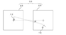
- FIG. 5 is a schematic diagram illustrating positions where the first camera and the second camera detect the first alignment mark and the second alignment mark, respectively, in the alignment correction step according to the first embodiment.
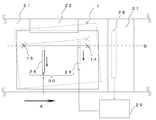
- It is the schematic explaining the movement of a 1st camera and a 2nd camera in the alignment correction step by 2nd Embodiment of this invention.
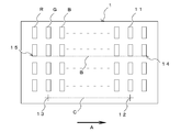
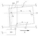
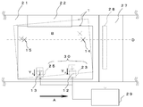
- FIG. 1 is a schematic view showing a substrate 1 to be exposed exposed by an alignment correction method for a substrate to be exposed according to the present invention (hereinafter simply referred to as “alignment correction method”) and an exposure apparatus according to the present invention.
- the substrate 1 to be exposed is a substrate such as a color filter used in a liquid crystal display, which is transported in a certain transport direction A by a transport unit 22 of an exposure apparatus described later, and is exposed by an exposure unit 27. As shown in FIG.
- a formed first alignment mark 12 and a second alignment mark 13 formed on the rear side are provided.
- each of the pixels 11 is formed in a substantially rectangular shape that is long in the direction perpendicular to the conveyance direction A (hereinafter simply referred to as “vertical direction”), and the periphery thereof is covered with a black matrix (BM).
- BM black matrix
- the lower right corner of the pixel 11 on the leading side in the transport direction A as opposed to the figure is used as a first observation point 14 for observing misalignment of the substrate to be exposed 1 and the pixel 11.
- the lower left corner of the pixel 11 on the rear side in the transport direction A formed in the same row is predetermined as the second observation point 15.
- first alignment mark 12 and the second alignment mark 13 include a straight line B connecting the first observation point 14 and the second observation point 15, the first alignment mark 12, the second alignment mark 13, and the like. And the straight line C connecting the two are parallel to each other.
- the first observation point 14 and the second observation point 15 can be defined in any row of the pixels 11 arranged in a lattice shape.
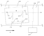
- an exposure apparatus that exposes the substrate 1 to be exposed includes a stage 21 on which the substrate 1 to be exposed is placed, a transport unit 22 that transports the substrate 1 to be exposed in a certain transport direction A, A first camera 23 and a first shaft 24 provided on the front side in the transport direction A; a second camera 25 and a second shaft 26 provided on the rear side; and an exposure means 27 for exposing the substrate 1 to be exposed.
- the line image sensor 28 provided on the rear side in the transport direction A of the exposure unit 27, the correction amount calculation unit 29, and the alignment correction unit 30 are included.
- the first camera 23 and the second camera 25 are cameras for detecting the first alignment mark 12 and the second alignment mark 13 to align the substrate 1 to be exposed, and are attached above the stage 21.
- the first axis 24 and the second axis 26 move in a plane parallel to the surface of the stage 21 while supporting the exposed substrate 1 placed on the stage 21 from below to align the exposed substrate 1.
- the line image sensor 28 detects the coordinates of the first observation point 14 and the second observation point 15 in order to observe the misalignment of the exposed substrate 1 conveyed in the conveyance direction A.
- a solid-state imaging device such as a CCD or CMOS is used.
- the correction amount calculation means 29 is predetermined according to the coordinates of the first observation point 14 and the second observation point 15 detected by the line image sensor 28 and the first observation point 14 and the second observation point 15.
- the alignment correction amount of the substrate 1 to be exposed is calculated based on the deviation from the reference line parallel to the transport direction A.
- the alignment correction unit 30 is configured by a combination of the first camera 23 and the second camera 25 or a combination of the first axis 24 and the second axis 26.
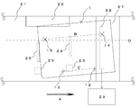
- the first alignment mark 12 and the second alignment mark 13 of the substrate 1 to be exposed first are detected by the first camera 23 and the second camera 25, respectively.
- the substrate 1 to be exposed is moved by the first shaft 24 and the second shaft 26 so that the alignment mark 12 and the second alignment mark 13 are in the center of the first camera 23 and the second camera 25. Align. In this case, for example, when the positions of the first camera 23 and the second camera 25 are shifted with respect to the transport direction A as shown in FIG.
- the position of the exposed substrate 1 aligned using the two cameras 25 is shifted according to the shift of the camera.
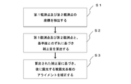
- Step S1 the coordinates of the first observation point 14 and the second observation point 15 that are set in advance on the substrate 1 to be exposed are detected.
- the transport of the first observation point 14 and the second observation point 15 is based on the time from observation of the first observation point 14 to observation of the second observation point 15.
- the coordinates in direction A can be determined.
- the detected first observation point 14 and the second observation point 14 are determined. From the coordinates of the observation point 15, the coordinates of the first alignment mark 12 and the second alignment mark 13 can be calculated.
- the coordinates of the first alignment mark 12 and the second alignment mark 13 may be detected by the line image sensor 28.
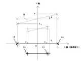
- the correction amount calculation unit 29 When the coordinate information of the first observation point 14 and the second observation point 15 is input to the correction amount calculation unit 29, the correction amount calculation unit 29 is placed at the set position of the first observation point 14 and the second observation point 15. Accordingly, the coordinate information of the reference line D that is predetermined and stored in the correction amount calculation means 29 and is parallel to the conveyance direction A is compared with the coordinate information of the first observation point 14 and the second observation point 15. Then, based on the deviation between the first observation point 14 and the second observation point 15 and the reference line D, a correction amount of alignment of the substrate 1 to be exposed is calculated (step S2).
- the reference line D is a first observation point 14 and a second observation point 15 that are detected by the line image sensor 28 in FIGS. 1, 4 and 5 when the substrate 1 to be exposed has been transported in an accurately aligned state. These are straight lines that are parallel to the transport direction A and are determined in advance according to the set positions of the first observation point 14 and the second observation point 15.
- the offset amount Y 1 is a correction amount in the Y-axis direction as a correction amount for correcting the coordinates
- the gain amount ⁇ is a rotation angle with respect to the X-axis.
- the alignment of the substrate 1 to be exposed exposed on the second and subsequent sheets is corrected by the correction amount thus calculated (step S3).
- the calculated correction amount is input from the correction amount calculation unit 29 to the alignment correction unit 30.
- the first camera 23 and the second camera 25 are used as the alignment correction means 30.
- the first alignment mark 12 and the second alignment mark 13 are formed in the same manner as the first substrate 1 to be exposed. After aligning the substrate 1 to be exposed so that it is positioned at the center of the first camera 23 and the second camera 25, the first alignment mark 12 and the second alignment mark 13 are placed on the substrate 1 to be exposed.
- the X coordinates of the first observation point 14, the second observation point 15, the first alignment mark 12, and the second alignment mark 13 are changed to a line by correcting the inclination.
- the amount of change is also a minute amount that can be ignored compared to the calculated correction amount. Therefore, the amount of change is also ignored in the above calculation formula. The same applies to the second and third embodiments.
- step S1 the detection of the coordinates of the first observation point 14 and the second observation point 15 (step S1) is the same as in the first embodiment.
- the first camera 23 and the second camera 25 are used as the alignment correction means 30.
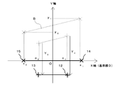
- the correction amount calculation means 29 is based on the deviation between the coordinates of the first observation point 14 and the second observation point 15 and the reference line D (X axis).
- First camera correction amount Y 2 and the second camera correction amount Y 3 can be obtained from the following equation.
- Y 2 ⁇ (y 1 ⁇ y 2 ) / (x 1 ⁇ x 2 ) ⁇ ⁇ (x 1 ⁇ c 1 ) ⁇ y 1
- Y 3 ⁇ (y 1 ⁇ y 2 ) / (x 1 ⁇ x 2 ) ⁇ ⁇ (x 1 ⁇ c 2 ) ⁇ y 1
- the alignment of the substrate 1 to be exposed exposed on the second and subsequent sheets is corrected by the correction amount thus calculated (step S3).
- the first camera 23 is moved in the Y-axis direction based on the correction amount input from the correction amount calculation means 29. moved by the correction amount Y 2, after moving the second camera 25 by a second camera correction amount Y 3, so as to detect a first alignment mark 12 and the second alignment marks 13 respectively.
- the shift that has occurred in the alignment of the first substrate 1 to be exposed is corrected as indicated by the broken line in FIG. 10, and the alignment of the substrate 1 to be exposed is appropriately performed as indicated by the solid line.
- the alignment is corrected by moving the first camera 23 and the second camera 25 themselves, even if the alignment accuracy during the alignment of the first substrate 1 to be exposed is significantly reduced, the first camera 23 and the second camera 25 If the displacement is within the movable range of the two cameras 25, the alignment of the substrate 1 to be exposed can be corrected.
- the detection of the coordinates of the first observation point 14 and the second observation point 15 (step S1) is the same as in the first embodiment and the second embodiment.
- the first axis 24 and the second axis 26 are used as the alignment correction means 30.
- the correction amount calculation means 29 is based on the deviation between the coordinates of the first observation point 14 and the second observation point 15 and the reference line D, and the first axis correction amount Y that is the correction amount of the first axis 24 in the Y-axis direction. 4, calculates a second axis correction amount Y 5 is a correction amount of the second shaft 26 (step S2).
- the calculation formula of this correction amount is the 1st camera correction amount in 2nd Embodiment.
- the calculation formula of the second camera correction amount can be obtained from the following equation.
- Y 4 ⁇ (y 1 ⁇ y 2 ) / (x 1 ⁇ x 2 ) ⁇ ⁇ (x 1 ⁇ c 1 ) ⁇ y 1
- Y 5 ⁇ (y 1 ⁇ y 2 ) / (x 1 ⁇ x 2 ) ⁇ ⁇ (x 1 ⁇ c 2 ) ⁇ y 1
- the alignment of the substrate 1 to be exposed exposed on the second and subsequent sheets is corrected by the correction amount calculated in this way (step S3).
- the first shaft 24 moves to the Y-axis direction by the first axis correction amount Y 4, by moving the second shaft 26 by the second axis correction amount Y 5, alignment of the substrate to be exposed 1 Correct.
- the deviation that has occurred in the alignment of the first substrate 1 to be exposed is corrected, and the alignment of the substrate 1 to be exposed is appropriately performed as shown by the solid line.
- the first camera 23 and the second camera 25 are fixed in order to correct the alignment by the first axis 24 and the second axis 26. Even when the substrate cannot be moved, the alignment of the exposed substrate 1 can be corrected.
- the correction amount calculating step (step S2) stores the calculated correction amount in the storage unit of the exposure apparatus for each of the exposed substrates 1 having different shapes, and the alignment correction step (step).
- the alignment of the exposed substrate 1 may be corrected using the correction amount stored for each exposed substrate 1 having a different shape.
- the first substrate to be exposed 1 is transported while being tilted with respect to the transport direction A. Therefore, in the first exposure of the substrate 1 to be exposed, the position of the edge of the pixel 11 along the straight line B is detected by the line image sensor 28, and between the position and a reference position preset in the line image sensor 28.
- the exposure means 27 follows the substrate 1 to be exposed by moving the exposure means 27 in a direction perpendicular to the transport direction A within a plane parallel to the surface of the stage 21 so that the amount of positional deviation of the image becomes a predetermined value. It is good to expose.
- the first exposed substrate 1 may be used as a dummy substrate.
Abstract
Description
図1は、本発明による被露光基板のアライメント補正方法(以下、単に「アライメント補正方法」という。)によって露光される被露光基板1と本発明による露光装置を示す概略図である。前記被露光基板1は、液晶ディスプレイに使用されるカラーフィルタなどの基板であり、後述する露光装置の搬送手段22によって一定の搬送方向Aに搬送され、露光手段27によって露光されるものであって、図2に示すように、その表面には、格子状に複数形成された赤(R)、緑(G)、青(B)の各色のピクセル11と、前記搬送方向Aの先頭部側に形成された第1アライメントマーク12と、後部側に形成された第2アライメントマーク13と、が設けられている。 Embodiments of the present invention will be described below in detail with reference to the accompanying drawings.
FIG. 1 is a schematic view showing a
まず、図3に示すように、最初に露光される被露光基板1の前記第1アライメントマーク12及び第2アライメントマーク13を、前記第1カメラ23及び第2カメラ25によりそれぞれ検知し、第1アライメントマーク12及び第2アライメントマーク13が、第1カメラ23及び第2カメラ25の中央にくるように、第1軸24及び第2軸26によって被露光基板1を移動し、被露光基板1をアライメントする。この場合、例えば、熱による露光装置の変形などにより、同図に示すように第1カメラ23及び第2カメラ25の位置が搬送方向Aに対してずれていたとき、前記第1カメラ23及び第2カメラ25を使用してアライメントされた被露光基板1の位置はカメラのずれに応じてずれた位置となる。 Next, a first embodiment of an alignment correction method for the
First, as shown in FIG. 3, the
Y1={(y1-y2)/(x1-x2)×x1}-y1
θ=-tan-1(y1-y2)/(x1-x2) In FIG. 7, in order to move the straight line B connecting the
Y 1 = {(y 1 −y 2 ) / (x 1 −x 2 ) × x 1 } −y 1
θ = −tan −1 (y 1 −y 2 ) / (x 1 −x 2 )
第2実施形態において、第1観測点14及び第2観測点15の座標の検出(ステップS1)は第1実施形態と同様である。第2実施形態において、アライメント補正手段30として第1カメラ23及び第2カメラ25が使用される。ステップS1を実施した後、図9に示すように、第1観測点14及び第2観測点15の座標と基準線D(X軸)とのずれに基づき、補正量算出手段29は、Y軸方向への第1カメラ23の補正量である第1カメラ補正量Y2と、第2カメラ25の補正量である第2カメラ補正量Y3とを算出する(ステップS2)。第1カメラ補正量Y2及び第2カメラ補正量Y3は、以下の式より求めることができる。
Y2={(y1-y2)/(x1-x2)}×(x1-c1)-y1
Y3={(y1-y2)/(x1-x2)}×(x1-c2)-y1 Furthermore, a second embodiment of the alignment correction method using the
In the second embodiment, the detection of the coordinates of the
Y 2 = {(y 1 −y 2 ) / (x 1 −x 2 )} × (x 1 −c 1 ) −y 1
Y 3 = {(y 1 −y 2 ) / (x 1 −x 2 )} × (x 1 −c 2 ) −y 1
第3実施形態において、第1観測点14及び第2観測点15の座標の検出(ステップS1)は第1実施形態及び第2実施形態と同様である。第3実施形態において、アライメント補正手段30として第1軸24及び第2軸26が使用される。補正量算出手段29は、第1観測点14及び第2観測点15の座標と基準線Dとのずれに基づき、Y軸方向への第1軸24の補正量である第1軸補正量Y4と、第2軸26の補正量である第2軸補正量Y5を算出する(ステップS2)。この補正量の算出式は、第1軸24及び第2軸26のX座標がそれぞれ第1カメラ23及び第2カメラ25のX座標と同じであれば、第2実施形態における第1カメラ補正量と第2カメラ補正量の算出式と同様となる。すなわち、第1軸補正量Y4及び第2軸補正量Y5は、以下の式より求めることができる。
Y4={(y1-y2)/(x1-x2)}×(x1-c1)-y1
Y5={(y1-y2)/(x1-x2)}×(x1-c2)-y1 Furthermore, a third embodiment of the alignment correction method using the
In the third embodiment, the detection of the coordinates of the
Y 4 = {(y 1 −y 2 ) / (x 1 −x 2 )} × (x 1 −c 1 ) −y 1
Y 5 = {(y 1 −y 2 ) / (x 1 −x 2 )} × (x 1 −c 2 ) −y 1
11…ピクセル
12…第1アライメントマーク
13…第2アライメントマーク
14…第1観測点
15…第2観測点
21…ステージ
22…搬送手段
23…第1カメラ
24…第1軸
25…第2カメラ
26…第2軸
27…露光手段
28…ラインイメージセンサ
29…補正量算出手段
30…アライメント補正手段
A…搬送方向
B…第1観測点と第2観測点とを結んだ直線
C…第1アライメントマークと第2アライメントマークとを結んだ直線
D…基準線
θ…ゲイン量
Y1…オフセット量
Y2…第1カメラ補正量
Y3…第2カメラ補正量
Y4…第1軸補正量
Y5…第2軸補正量
DESCRIPTION OF
Claims (6)
- 搬送手段により搬送方向に搬送される被露光基板を、順次露光する際に、前に露光された被露光基板のアライメントのずれに基づき、後に露光される被露光基板のアライメントを補正する被露光基板のアライメント補正方法であって、
前記搬送方向に搬送されてきた被露光基板のアライメントのずれを観測するために、被露光基板上に予め定められた第1観測点及び第2観測点の座標を検出する座標検出ステップと、
前記検出された座標と前記第1観測点及び第2観測点に応じて予め定められた基準線とのずれに基づき補正量を算出する補正量算出ステップと、
前記算出された補正量に基づき後に露光される被露光基板のアライメントを補正するアライメント補正ステップと、
を行う被露光基板のアライメント補正方法。 When sequentially exposing the substrate to be exposed that is transported in the transport direction by the transport means, the substrate to be exposed that corrects the alignment of the substrate to be exposed later based on the misalignment of the previously exposed substrate to be exposed An alignment correction method of
A coordinate detection step of detecting coordinates of a first observation point and a second observation point that are predetermined on the substrate to be exposed in order to observe a misalignment of the substrate to be exposed that has been transported in the transport direction;
A correction amount calculating step for calculating a correction amount based on a deviation between the detected coordinates and a reference line predetermined according to the first observation point and the second observation point;
An alignment correction step of correcting the alignment of a substrate to be exposed later based on the calculated correction amount;
An alignment correction method for a substrate to be exposed. - 前記被露光基板のアライメントは、前記搬送方向の先頭部側に設けられた第1カメラ及び後部方向に設けられた第2カメラによって、被露光基板の表面に形成された第1アライメントマーク及び第2アライメントマークを検知した情報に基づき行われ、
前記補正量算出ステップは、前記第1観測点及び第2観測点の座標と前記基準線とのずれに基づき、被露光基板の搬送方向の先頭部側に設けられ第1アライメントマーク及び後部側に設けられた第2アライメントマークの搬送面に平行な面内にて前記搬送方向と交差する方向への補正量であるオフセット量と、前記被露光基板の基準線に対する傾きの補正量であるゲイン量とを算出し、
前記アライメント補正ステップは、前記第1カメラ及び第2カメラによって前記第1アライメントマーク及び第2アライメントマークを検知して前記被露光基板をアライメントした後、前記第1アライメントマーク及び第2アライメントマークを、該両者の中心に対してそれぞれ点対称に前記ゲイン量だけ回転し、前記搬送方向に対して交差する方向に前記オフセット量だけ移動することによって前記被露光基板のアライメントを補正することを特徴とする請求項1に記載の被露光基板のアライメント補正方法。 The alignment of the substrate to be exposed is performed by a first alignment mark and a second alignment mark formed on the surface of the substrate to be exposed by a first camera provided on the leading side in the transport direction and a second camera provided in the rear direction. Based on the information that detected the alignment mark,
The correction amount calculating step is provided on the first alignment mark and rear side on the leading side in the transport direction of the substrate to be exposed based on the deviation between the coordinates of the first observation point and the second observation point and the reference line. An offset amount that is a correction amount in a direction crossing the transport direction in a plane parallel to the transport surface of the provided second alignment mark, and a gain amount that is a correction amount of an inclination with respect to a reference line of the substrate to be exposed And
In the alignment correction step, the first alignment mark and the second alignment mark are detected by the first camera and the second camera to align the exposed substrate, and then the first alignment mark and the second alignment mark are The alignment of the substrate to be exposed is corrected by rotating by the gain amount symmetrically with respect to the center of both and moving by the offset amount in a direction intersecting the transport direction. The alignment correction method for a substrate to be exposed according to claim 1. - 前記被露光基板のアライメントは、前記搬送方向の先頭部側に設けられた第1カメラ及び後部方向に設けられた第2カメラによって、被露光基板の表面に形成された第1アライメントマーク及び第2アライメントマークを検知した情報に基づき行われ、
前記補正量算出ステップは、前記第1観測点及び第2観測点の座標と前記基準線とのずれに基づき、搬送面に平行な面内にて前記搬送方向と交差する方向への前記第1カメラの補正量である第1カメラ補正量と、前記第2カメラの補正量である第2カメラ補正量とを算出し、
前記アライメント補正ステップは、前記搬送方向と交差する方向へ前記第1カメラを前記第1カメラ補正量だけ移動し、前記第2カメラを前記第2カメラ補正量だけ移動することにより、前記被露光基板のアライメントを補正することを特徴とする請求項1に記載の被露光基板のアライメント補正方法。 The alignment of the substrate to be exposed is performed by a first alignment mark and a second alignment mark formed on the surface of the substrate to be exposed by a first camera provided on the leading side in the transport direction and a second camera provided in the rear direction. Based on the information that detected the alignment mark,
In the correction amount calculating step, the first direction in the direction intersecting the transport direction within a plane parallel to the transport surface is determined based on a deviation between the coordinates of the first observation point and the second observation point and the reference line. Calculating a first camera correction amount that is a camera correction amount and a second camera correction amount that is a correction amount of the second camera;
The alignment correction step moves the first camera in the direction intersecting the transport direction by the first camera correction amount, and moves the second camera by the second camera correction amount to thereby expose the substrate to be exposed. The alignment correction method for a substrate to be exposed according to claim 1, wherein the alignment is corrected. - 前記被露光基板のアライメントは、前記搬送方向の先頭部側に設けられた第1カメラ及び後部方向に設けられた第2カメラによって、被露光基板の表面に形成された第1アライメントマーク及び第2アライメントマークを検知した情報に基づき行われ、
前記補正量算出ステップは、前記第1観測点及び第2観測点の座標と前記基準線とのずれに基づき、搬送面に平行な面内にて前記搬送方向と交差する方向への前記第1軸の補正量である第1軸補正量と、前記第2軸の補正量である第2軸補正量とを算出し、
前記アライメント補正ステップは、前記第1カメラ及び第2カメラによって前記第1アライメントマーク及び第2アライメントマークを検知して前記被露光基板をアライメントした後、前記搬送方向と交差する方向へ前記第1軸を第1軸補正量だけ移動し、前記第2軸を第2軸補正量だけ移動することにより、前記被露光基板のアライメントを補正することを特徴とする請求項1に記載の被露光基板のアライメント補正方法。 The alignment of the substrate to be exposed is performed by a first alignment mark and a second alignment mark formed on the surface of the substrate to be exposed by a first camera provided on the leading side in the transport direction and a second camera provided in the rear direction. Based on the information that detected the alignment mark,
In the correction amount calculating step, the first direction in the direction intersecting the transport direction within a plane parallel to the transport surface is determined based on a deviation between the coordinates of the first observation point and the second observation point and the reference line. Calculating a first axis correction amount that is an axis correction amount and a second axis correction amount that is a correction amount of the second axis;
The alignment correction step detects the first alignment mark and the second alignment mark by the first camera and the second camera, aligns the substrate to be exposed, and then moves the first axis in a direction intersecting the transport direction. The alignment of the substrate to be exposed is corrected by moving the second axis by a first axis correction amount and moving the second axis by a second axis correction amount. Alignment correction method. - 前記補正量算出ステップは、形状の異なる被露光基板ごとに、算出された補正量を記憶手段に記憶し、
前記アライメント補正ステップは、形状の異なる被露光基板ごとに記憶された前記補正量を使用して、前記被露光基板のアライメントを補正することを特徴とする請求項1~4のいずれか1項に記載の被露光基板のアライメント補正方法。 The correction amount calculating step stores the calculated correction amount in a storage unit for each substrate to be exposed having a different shape,
5. The alignment correction step according to claim 1, wherein the alignment correction step corrects alignment of the substrate to be exposed using the correction amount stored for each of the substrates to be exposed having different shapes. An alignment correction method for a substrate to be exposed. - 搬送手段により搬送方向に搬送される被露光基板を、順次露光する際に、前に露光された被露光基板のアライメントのずれに基づき、後に露光される被露光基板のアライメントを補正して露光する露光装置であって、
前記搬送方向に搬送されてきた被露光基板のアライメントのずれを観測するために、被露光基板上に予め定められた第1観測点及び第2観測点の座標を検出する座標検出手段と、
前記検出された座標と前記第1観測点及び第2観測点に応じて予め定められた基準線とのずれに基づき補正量を算出する補正量算出手段と、
前記算出された補正量に基づき後に露光される被露光基板のアライメントを補正するアライメント補正手段と、
を備えた露光装置。 When sequentially exposing the substrate to be exposed conveyed in the conveying direction by the conveying means, the exposure is performed by correcting the alignment of the substrate to be exposed later, based on the misalignment of the previously exposed substrate to be exposed. An exposure apparatus,
A coordinate detection means for detecting coordinates of a first observation point and a second observation point which are predetermined on the substrate to be exposed in order to observe a misalignment of the substrate to be exposed that has been transported in the transport direction;
A correction amount calculating means for calculating a correction amount based on a deviation between the detected coordinates and a reference line predetermined according to the first observation point and the second observation point;
Alignment correction means for correcting alignment of a substrate to be exposed later based on the calculated correction amount;
An exposure apparatus comprising:
Priority Applications (3)
| Application Number | Priority Date | Filing Date | Title |
|---|---|---|---|
| KR1020147005146A KR20140056298A (en) | 2011-08-03 | 2012-07-30 | Method for correcting alignment of substrate to be exposed, and exposure device |
| CN201280037975.0A CN103733138B (en) | 2011-08-03 | 2012-07-30 | Be exposed positioning correction method and the exposure device of substrate |
| US14/168,212 US9360776B2 (en) | 2011-08-03 | 2014-01-30 | Alignment correction method for substrate to be exposed, and exposure apparatus |
Applications Claiming Priority (2)
| Application Number | Priority Date | Filing Date | Title |
|---|---|---|---|
| JP2011170292A JP5704606B2 (en) | 2011-08-03 | 2011-08-03 | Alignment correction method and exposure apparatus for substrate to be exposed |
| JP2011-170292 | 2011-08-03 |
Related Child Applications (1)
| Application Number | Title | Priority Date | Filing Date |
|---|---|---|---|
| US14/168,212 Continuation US9360776B2 (en) | 2011-08-03 | 2014-01-30 | Alignment correction method for substrate to be exposed, and exposure apparatus |
Publications (1)
| Publication Number | Publication Date |
|---|---|
| WO2013018762A1 true WO2013018762A1 (en) | 2013-02-07 |
Family
ID=47629284
Family Applications (1)
| Application Number | Title | Priority Date | Filing Date |
|---|---|---|---|
| PCT/JP2012/069339 WO2013018762A1 (en) | 2011-08-03 | 2012-07-30 | Method for correcting alignment of substrate to be exposed, and exposure device |
Country Status (6)
| Country | Link |
|---|---|
| US (1) | US9360776B2 (en) |
| JP (1) | JP5704606B2 (en) |
| KR (1) | KR20140056298A (en) |
| CN (1) | CN103733138B (en) |
| TW (1) | TWI531876B (en) |
| WO (1) | WO2013018762A1 (en) |
Cited By (1)
| Publication number | Priority date | Publication date | Assignee | Title |
|---|---|---|---|---|
| WO2023189435A1 (en) * | 2022-03-31 | 2023-10-05 | 株式会社ニコン | Analysis system, light exposure method, light exposure apparatus, and device |
Families Citing this family (14)
| Publication number | Priority date | Publication date | Assignee | Title |
|---|---|---|---|---|
| CN104677314A (en) | 2015-03-02 | 2015-06-03 | 合肥京东方光电科技有限公司 | Device and method for detecting surface flatness of display panel |
| CN104678622A (en) * | 2015-03-26 | 2015-06-03 | 合肥鑫晟光电科技有限公司 | Array substrate detection method and system |
| US20170323708A1 (en) * | 2016-05-03 | 2017-11-09 | Texas Instruments Incorporated | Component sheet and method of singulating |
| CN106086786B (en) * | 2016-08-19 | 2018-06-05 | 京东方科技集团股份有限公司 | offset calibration method and system |
| JP6717382B2 (en) | 2016-09-30 | 2020-07-01 | 日本電産リード株式会社 | Length measuring device |
| KR101874409B1 (en) * | 2016-10-25 | 2018-07-04 | 에이피시스템 주식회사 | The align-inspection device and the method using the same |
| CN106502057B (en) * | 2016-11-25 | 2018-07-27 | 天津津芯微电子科技有限公司 | Scaling method and calibration system |
| CN108267871B (en) * | 2017-01-04 | 2020-12-04 | 京东方科技集团股份有限公司 | Angle adjustment tool |
| DE102017123686A1 (en) | 2017-10-11 | 2019-04-11 | Miva Technologies Gmbh | Method and exposure device for exposing at least one stored representation on a photosensitive recording medium |
| CN108198219B (en) * | 2017-11-21 | 2022-05-13 | 合肥工业大学 | Error compensation method for camera calibration parameters for photogrammetry |
| CN109969807B (en) * | 2019-05-29 | 2019-08-16 | 湖南思威博恒智能科技有限责任公司 | Automatic deviation correction clamp for stacking, robot palletizer and pallet method for correcting error |
| DE102019122839A1 (en) * | 2019-08-26 | 2021-03-04 | Miva Technologies Gmbh | Method and exposure device for exposing a light-sensitive recording medium |
| CN112117316A (en) * | 2020-09-23 | 2020-12-22 | 京东方科技集团股份有限公司 | Display mother board, preparation method and alignment method of display mother board |
| CN113382231B (en) * | 2021-06-08 | 2023-04-07 | 京东方科技集团股份有限公司 | Display panel detection method, device, equipment and storage medium |
Citations (5)
| Publication number | Priority date | Publication date | Assignee | Title |
|---|---|---|---|---|
| JP2003162068A (en) * | 2001-11-29 | 2003-06-06 | Dainippon Screen Mfg Co Ltd | Laser drawing method and device |
| JP2006337874A (en) * | 2005-06-03 | 2006-12-14 | Fujifilm Holdings Corp | Exposure device and exposure method |
| JP2009230008A (en) * | 2008-03-25 | 2009-10-08 | Fujifilm Corp | Exposure apparatus and exposure method |
| JP2010054849A (en) * | 2008-08-28 | 2010-03-11 | Nsk Ltd | Scan exposure apparatus and scan exposure method |
| JP2010231062A (en) * | 2009-03-27 | 2010-10-14 | Dainippon Screen Mfg Co Ltd | Drawing apparatus and drawing method |
Family Cites Families (3)
| Publication number | Priority date | Publication date | Assignee | Title |
|---|---|---|---|---|
| TW200641564A (en) * | 2005-02-24 | 2006-12-01 | Fuji Photo Film Co Ltd | The correction method of plotting device |
| JP2008076709A (en) | 2006-09-21 | 2008-04-03 | V Technology Co Ltd | Exposure device |
| CN100520599C (en) * | 2007-09-17 | 2009-07-29 | 上海微电子装备有限公司 | Asymmetric transmission mark combination and its aligning method |
-
2011
- 2011-08-03 JP JP2011170292A patent/JP5704606B2/en not_active Expired - Fee Related
-
2012
- 2012-07-30 WO PCT/JP2012/069339 patent/WO2013018762A1/en active Application Filing
- 2012-07-30 CN CN201280037975.0A patent/CN103733138B/en not_active Expired - Fee Related
- 2012-07-30 KR KR1020147005146A patent/KR20140056298A/en not_active Application Discontinuation
- 2012-08-03 TW TW101127907A patent/TWI531876B/en not_active IP Right Cessation
-
2014
- 2014-01-30 US US14/168,212 patent/US9360776B2/en active Active
Patent Citations (5)
| Publication number | Priority date | Publication date | Assignee | Title |
|---|---|---|---|---|
| JP2003162068A (en) * | 2001-11-29 | 2003-06-06 | Dainippon Screen Mfg Co Ltd | Laser drawing method and device |
| JP2006337874A (en) * | 2005-06-03 | 2006-12-14 | Fujifilm Holdings Corp | Exposure device and exposure method |
| JP2009230008A (en) * | 2008-03-25 | 2009-10-08 | Fujifilm Corp | Exposure apparatus and exposure method |
| JP2010054849A (en) * | 2008-08-28 | 2010-03-11 | Nsk Ltd | Scan exposure apparatus and scan exposure method |
| JP2010231062A (en) * | 2009-03-27 | 2010-10-14 | Dainippon Screen Mfg Co Ltd | Drawing apparatus and drawing method |
Cited By (1)
| Publication number | Priority date | Publication date | Assignee | Title |
|---|---|---|---|---|
| WO2023189435A1 (en) * | 2022-03-31 | 2023-10-05 | 株式会社ニコン | Analysis system, light exposure method, light exposure apparatus, and device |
Also Published As
| Publication number | Publication date |
|---|---|
| JP5704606B2 (en) | 2015-04-22 |
| CN103733138A (en) | 2014-04-16 |
| TW201321908A (en) | 2013-06-01 |
| CN103733138B (en) | 2016-03-30 |
| TWI531876B (en) | 2016-05-01 |
| JP2013037034A (en) | 2013-02-21 |
| KR20140056298A (en) | 2014-05-09 |
| US20140146299A1 (en) | 2014-05-29 |
| US9360776B2 (en) | 2016-06-07 |
Similar Documents
| Publication | Publication Date | Title |
|---|---|---|
| JP5704606B2 (en) | Alignment correction method and exposure apparatus for substrate to be exposed | |
| JP7247013B2 (en) | Alignment method, vapor deposition method using same, and method for manufacturing electronic device | |
| JP4705526B2 (en) | Alignment apparatus and method | |
| JP4854998B2 (en) | Manufacturing method of liquid crystal display device | |
| JP4592021B2 (en) | Alignment apparatus and method | |
| KR102112430B1 (en) | Transfer device for electronic device and transfer method for electronic device | |
| JP2006240015A (en) | Pattern forming apparatus, alignment apparatus, substrate handling apparatus, pattern formation method, and substrate handling method | |
| US8778576B2 (en) | Exposure method and exposure device | |
| JP2004303559A (en) | Alignment device, alignment method, and organic el element manufactured by using the same | |
| WO2018147339A1 (en) | Vapor deposition mask, vapor deposition mask alignment method, and vapor deposition mask-securing device | |
| JP5145530B2 (en) | Photomask and exposure method using the same | |
| JP2017134375A (en) | Exposure apparatus and exposure method | |
| JP2006292426A (en) | Coordinate-measuring method and dimension measuring method | |
| JP2007315882A (en) | Apparatus and method for positioning substrate, and device and method for manufacturing color filter | |
| JP3936546B2 (en) | Exposure apparatus, substrate positioning method in the apparatus, and flat display panel manufacturing method | |
| US9362153B2 (en) | Method for aligning substrates in different spaces and having different sizes | |
| JP5076233B2 (en) | Method for adjusting initial position and orientation of exposure mask | |
| JP2012220439A (en) | Pattern inspection method and pattern inspection apparatus | |
| JP2006112933A (en) | Alignment mark inspection method and program | |
| JP2016031524A (en) | Alignment system | |
| KR101239821B1 (en) | robot for transporting substrate and alignment method of the same | |
| JP5398314B2 (en) | Exposure apparatus and exposure method | |
| JP4860366B2 (en) | Surface mount equipment | |
| JPH0917710A (en) | Method and device for aligning exposure film | |
| JP2011118205A (en) | Alignment method |
Legal Events
| Date | Code | Title | Description |
|---|---|---|---|
| WWE | Wipo information: entry into national phase |
Ref document number: 201280037975.0 Country of ref document: CN |
|
| 121 | Ep: the epo has been informed by wipo that ep was designated in this application |
Ref document number: 12820314 Country of ref document: EP Kind code of ref document: A1 |
|
| NENP | Non-entry into the national phase |
Ref country code: DE |
|
| ENP | Entry into the national phase |
Ref document number: 20147005146 Country of ref document: KR Kind code of ref document: A |
|
| 122 | Ep: pct application non-entry in european phase |
Ref document number: 12820314 Country of ref document: EP Kind code of ref document: A1 |