WO2013018750A1 - 表示装置 - Google Patents
表示装置 Download PDFInfo
- Publication number
- WO2013018750A1 WO2013018750A1 PCT/JP2012/069299 JP2012069299W WO2013018750A1 WO 2013018750 A1 WO2013018750 A1 WO 2013018750A1 JP 2012069299 W JP2012069299 W JP 2012069299W WO 2013018750 A1 WO2013018750 A1 WO 2013018750A1
- Authority
- WO
- WIPO (PCT)
- Prior art keywords
- eye
- phase difference
- region
- pixel
- light
- Prior art date
- Legal status (The legal status is an assumption and is not a legal conclusion. Google has not performed a legal analysis and makes no representation as to the accuracy of the status listed.)
- Ceased
Links
Images

Classifications
-
- G—PHYSICS
- G02—OPTICS
- G02F—OPTICAL DEVICES OR ARRANGEMENTS FOR THE CONTROL OF LIGHT BY MODIFICATION OF THE OPTICAL PROPERTIES OF THE MEDIA OF THE ELEMENTS INVOLVED THEREIN; NON-LINEAR OPTICS; FREQUENCY-CHANGING OF LIGHT; OPTICAL LOGIC ELEMENTS; OPTICAL ANALOGUE/DIGITAL CONVERTERS
- G02F1/00—Devices or arrangements for the control of the intensity, colour, phase, polarisation or direction of light arriving from an independent light source, e.g. switching, gating or modulating; Non-linear optics
- G02F1/01—Devices or arrangements for the control of the intensity, colour, phase, polarisation or direction of light arriving from an independent light source, e.g. switching, gating or modulating; Non-linear optics for the control of the intensity, phase, polarisation or colour
- G02F1/13—Devices or arrangements for the control of the intensity, colour, phase, polarisation or direction of light arriving from an independent light source, e.g. switching, gating or modulating; Non-linear optics for the control of the intensity, phase, polarisation or colour based on liquid crystals, e.g. single liquid crystal display cells
- G02F1/133—Constructional arrangements; Operation of liquid crystal cells; Circuit arrangements
- G02F1/1333—Constructional arrangements; Manufacturing methods
- G02F1/1335—Structural association of cells with optical devices, e.g. polarisers or reflectors
- G02F1/13363—Birefringent elements, e.g. for optical compensation
-
- G—PHYSICS
- G02—OPTICS
- G02B—OPTICAL ELEMENTS, SYSTEMS OR APPARATUS
- G02B30/00—Optical systems or apparatus for producing three-dimensional [3D] effects, e.g. stereoscopic images
- G02B30/20—Optical systems or apparatus for producing three-dimensional [3D] effects, e.g. stereoscopic images by providing first and second parallax images to an observer's left and right eyes
- G02B30/22—Optical systems or apparatus for producing three-dimensional [3D] effects, e.g. stereoscopic images by providing first and second parallax images to an observer's left and right eyes of the stereoscopic type
- G02B30/25—Optical systems or apparatus for producing three-dimensional [3D] effects, e.g. stereoscopic images by providing first and second parallax images to an observer's left and right eyes of the stereoscopic type using polarisation techniques
-
- G—PHYSICS
- G02—OPTICS
- G02B—OPTICAL ELEMENTS, SYSTEMS OR APPARATUS
- G02B5/00—Optical elements other than lenses
- G02B5/30—Polarising elements
- G02B5/3016—Polarising elements involving passive liquid crystal elements
Definitions
- the present technology relates to a display device including a phase difference element that changes a polarization state of light.
- Patent Documents 1 and 2 in order to emit light having different polarization states in the left-eye pixel and the right-eye pixel, a phase difference element in which a liquid crystal cell is partially formed, or a plurality of mutually different slow axes are used. It has been proposed to provide a phase difference element in which a kind of phase difference material is arranged.
- Patent Document 3 proposes to provide a retardation element formed by applying a liquid crystal on a patterned photo-alignment film and polymerizing it.
- phase difference element is disposed on the video display surface of the stereoscopic video display device. Therefore, when the distance between the phase difference element and the image display surface is long and the viewer views the image display surface from an oblique direction, a positional deviation between the liquid crystal cell and the phase difference element in the display panel occurs. The characteristic (crosstalk) may be deteriorated.
- a display device includes a display panel in which a plurality of pixels are arranged in a matrix and a phase difference element bonded to the display panel.
- the phase difference element has a phase difference layer in which two or more types of phase difference regions having different slow axis directions are arranged corresponding to each pixel.
- P Pixel pitch d: Distance between pixel and the phase difference element
- a swell of amplitude a satisfying the following expression is provided in a side portion in contact with another type of phase difference region.
- the display device since it is possible to suppress the entry of light due to the undulation of the side portions of each phase difference region, it is possible to reduce the degradation of crosstalk.
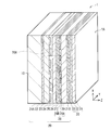
- FIG. 2 is a cross-sectional view illustrating an example of an internal configuration of the display device in FIG. 1.
- FIG. 3 is a cross-sectional view illustrating an example of a configuration of the phase difference element in FIG. 2. It is sectional drawing showing an example of a structure of the alignment film of FIG. It is a conceptual diagram showing an example of the slow axis of the phase difference area for right eyes and the phase difference area for left eyes of FIG. 3 together with the slow axis or the transmission axis of another optical member. It is a perspective view showing an example of a structure of the optical element for right eyes of the polarized glasses of FIG. 1, and the optical element for left eyes.
- FIG. 3 is an enlarged cross-sectional view illustrating a part of the display panel and the phase difference element in FIG. 2. It is a figure showing the relationship between (phi) and amax ((phi)). It is a figure showing an example of the relationship between a viewing angle and crosstalk. It is a schematic diagram for demonstrating an example of the manufacturing method of the phase difference element of FIG. It is a conceptual diagram for demonstrating an example of the slow axis and transmission axis at the time of observing the image
- FIG. 1 is a perspective view of a display device 1 according to an embodiment of the present technology together with polarized glasses 2 described later.
- FIG. 2 illustrates an example of a cross-sectional configuration of the display device 1 of FIG.
- the display device 1 is a polarized glasses type display device that displays a stereoscopic image to an observer (not shown) wearing the polarized glasses 2 in front of the eyeball.
- the display device 1 is configured by laminating a backlight unit 10, a liquid crystal display panel 20, and a retardation element 30 in this order.
- the surface of the phase difference element 30 is an image display surface 1 ⁇ / b> A and is directed toward the observer side.
- the display device 1 is arranged so that the video display surface 1A is parallel to the vertical surface (vertical surface).
- the video display surface 1A has, for example, a rectangular shape, and the longitudinal direction of the video display surface 1A is, for example, parallel to the horizontal direction (y-axis direction in the figure). It is assumed that the observer observes the video display surface 1A after wearing the polarizing glasses 2 in front of the eyeball.
- the polarized glasses 2 are of a circularly polarized type, and the display device 1 is a display device for circularly polarized glasses.
- the backlight unit 10 illuminates the liquid crystal display panel 20 from behind, and includes, for example, a reflector, a light source, and an optical sheet (none of which are shown).
- the reflection plate returns the light emitted from the light source to the optical sheet side, and has functions such as reflection, scattering, and diffusion.
- the light source is, for example, a plurality of linear light sources arranged in parallel at equal intervals, or a plurality of point light sources arranged two-dimensionally. Examples of the linear light source include a hot cathode fluorescent lamp (HCFL) and a cold cathode fluorescent lamp (CCFL). Examples of the point light source include a light emitting diode (LED).
- the optical sheet equalizes the in-plane luminance distribution of light from the light source, or adjusts the divergence angle and polarization state of light from the light source within a desired range.
- a diffusion plate, a diffusion sheet, A prism sheet, a reflective polarizing element, a phase difference plate, and the like are included.
- the light source may be of an edge light type, and in that case, a light guide plate or a light guide film is used as necessary.
- the liquid crystal display panel 20 is a transmissive display panel in which a plurality of pixels are two-dimensionally arranged, and displays an image by driving each pixel according to a video signal.
- the liquid crystal display panel 20 includes a polarizer 21 ⁇ / b> A, a transparent substrate 22, a pixel electrode 23, an alignment film 24, a liquid crystal layer 25, an alignment film 26, and a common electrode in order from the backlight unit 10 side. 27, a color filter 28, a transparent substrate 29, and a polarizer 21B.
- the polarizer 21A is a polarizing plate disposed on the light incident side of the liquid crystal display panel 20, and the polarizer 21B is a polarizing plate disposed on the light emission side of the liquid crystal display panel 20.
- the polarizers 21A and 21B are a kind of optical shutter, and allow only light (polarized light) having a certain vibration direction to pass therethrough.
- Each of the polarizers 21A and 21B is disposed, for example, so that the polarization axes thereof are different from each other by a predetermined angle (for example, 90 degrees), whereby the light emitted from the backlight unit 10 is transmitted through the liquid crystal layer, Or it is cut off.
- a polarizing plate is not limited to plate shape.
- the direction of the transmission axis of the polarizer 21A is set within a range where light emitted from the backlight unit 10 can be transmitted.
- the transmission axis of the polarizer 21A is also directed in the vertical direction, and the polarization of the light emitted from the backlight unit 10 is
- the axis is in the horizontal direction
- the transmission axis of the polarizer 21A is also in the horizontal direction.
- the light emitted from the backlight unit 10 is not limited to linearly polarized light, and may be circularly polarized light, elliptically polarized light, or non-polarized light.
- the direction of the polarization axis of the polarizer 21B is set within a range where light transmitted through the liquid crystal display panel 20 can be transmitted.
- the polarization axis of the polarizer 21A is in the horizontal direction
- the polarization axis of the polarizer 21B is in a direction (vertical direction) orthogonal to the polarization axis of the polarizer 21A.
- the orientation of the polarization axis of the polarizer 21A is the vertical direction
- the polarization axis of the polarizer 21B is oriented in the direction (horizontal direction) orthogonal to the polarization axis of the polarizer 21A.
- the polarization axis and the transmission axis are synonymous with each other.
- the transparent substrates 22 and 29 are generally substrates that are transparent to visible light.
- the transparent substrate 22 on the backlight unit 10 side is formed with, for example, an active driving circuit including TFTs (Thin Film Transistors) as wiring elements electrically connected to the pixel electrodes 23 and wiring.
- TFTs Thin Film Transistors
- the pixel electrode 23 is made of, for example, indium tin oxide (ITO), and functions as an electrode for each pixel.
- the alignment films 24 and 26 are made of, for example, a polymer material such as polyimide, and perform alignment processing on the liquid crystal.
- the liquid crystal layer 25 is made of, for example, VA (Vertical Alignment) mode, IPS (In-Plane (Switching) mode, TN (Twisted Nematic) mode, or STN (Super w Twisted Nematic) mode liquid crystal.
- the liquid crystal layer 25 has a function of transmitting or blocking light emitted from the backlight unit 10 for each pixel by an applied voltage from a drive circuit (not shown).
- the common electrode 27 is made of, for example, ITO and functions as a common counter electrode for the pixel electrodes 23.
- the color filter 28 has a plurality of filter portions 28A arranged corresponding to the pixel electrodes 23 and a black matrix portion 28B arranged corresponding to the peripheral region of the pixel electrodes 23.
- the filter unit 28A has light transmittance, and color-separates light from the backlight unit 10 into, for example, red, green, or blue.
- the black matrix portion 28B has a light shielding property.
- a portion facing the filter unit 28A constitutes a pixel 20A of the liquid crystal display panel 20, and the filter unit 28A is disposed on the video display surface 1A side in the pixel 20A.
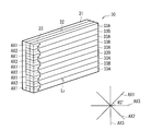
- FIG. 3 is a perspective view showing an example of the configuration of the phase difference element 30.
- the phase difference element 30 changes the polarization state of the light transmitted through the polarizer 21 ⁇ / b> B of the liquid crystal display panel 20.
- the phase difference element 30 is affixed to the surface (polarizer 21B) of the light emission side of the liquid crystal display panel 20 with an adhesive (not shown) or the like.
- the retardation element 30 includes a base material 31, an alignment film 32, and a retardation layer 33 in order from the image display surface 1 ⁇ / b> A side.
- the base material 31, the alignment film 32, and the retardation layer 33 may be arranged in this order from the liquid crystal display panel 20 side.
- the base material 31 supports the alignment film 32 and the retardation layer 33, and is made of, for example, a transparent resin film.
- a transparent resin film those having a small optical anisotropy, that is, a birefringence are preferred.
- the alignment film 32 has a function of specifically aligning an alignment material such as liquid crystal.
- the alignment film 32 is made of a transparent resin, for example, a UV curable type, an electron beam curable type, or a thermoplastic transparent resin.
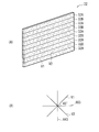
- the alignment film 32 is provided on the surface of the substrate 31. For example, as shown in FIG. 4A, two types of alignment regions having different alignment directions (right-eye alignment region 32A, left-eye alignment region). 32B).
- the right-eye alignment region 32A and the left-eye alignment region 32B have, for example, a belt-like shape extending in one common direction (horizontal direction), and are shorter than the right-eye alignment region 32A and the left-eye alignment region 32B. They are alternately arranged in the direction (vertical direction).
- the side portion extending in the longitudinal direction (horizontal direction) of the right-eye alignment region 32A and the side portion extending in the longitudinal direction (horizontal direction) of the left-eye alignment region 32B are in contact with each other.
- the right-eye alignment region 32A and the left-eye alignment region 32B are arranged corresponding to the pixels 20A of the liquid crystal display panel 20, for example, a pitch corresponding to the pixel pitch in the short direction (vertical direction) of the liquid crystal display panel 20. Is arranged in.
- the right-eye alignment region 32A has a plurality of grooves V1 extending in a direction intersecting with the polarization axis AX3 of the polarizer 21B at 45 °. Yes.
- the left-eye alignment region 32B is in a direction intersecting with the polarization axis AX3 of the polarizer 21B at 45 ° and extending the groove V1. It has the some groove
- each of the grooves V1 and V2 extends obliquely in a 45 ° direction when the polarization axis AX3 of the polarizer 21B is oriented in the vertical direction or the horizontal direction.
- the groove V1 extends, for example, in the horizontal direction
- the groove V2 extends, for example, in the vertical direction.
- Each groove V1 may extend linearly in one direction, or may extend in one direction while fluctuating (meandering), for example.
- the cross-sectional shape of each groove V1 is V-shaped, for example.
- the cross-sectional shape of each groove V2 is, for example, V-shaped.
- the entire cross-sectional shape of the right-eye alignment region 32A and the left-eye alignment region 32B is serrated.
- the pitch is preferably smaller, several ⁇ m or less, and more preferably several hundred nm or less. Such a shape is collectively formed, for example, by transfer using a mold.
- the alignment film 32 is not based on the groove structure shown above, but may be a photo-alignment film formed by polarized UV irradiation.
- the photo-alignment film is preliminarily coated with a material that aligns in the UV polarization direction when irradiated with polarized UV, and UV light polarized in different directions is irradiated to the right-eye alignment region 32A and the left-eye alignment region 32B. Can be manufactured.
- the retardation layer 33 is a thin layer having optical anisotropy.
- the retardation layer 33 is provided on the surfaces of the right-eye alignment region 32A and the left-eye alignment region 32B, for example.
- the phase difference layer 33 includes two types of phase difference regions (a right-eye phase difference region 33 ⁇ / b> A and a left-eye phase difference region 33 ⁇ / b> B) having different slow axis directions. .
- the right-eye retardation region 33A is formed on the right-eye alignment region 32A
- the left-eye retardation region 33B is formed on the left-eye alignment region 32B. Accordingly, the right-eye retardation region 33A and the left-eye retardation region 33B have a band-like shape extending in one common direction (horizontal direction), like the right-eye alignment region 32A and the left-eye alignment region 32B. Yes. Furthermore, the right-eye phase difference region 33A and the left-eye phase difference region 33B are alternately arranged in the short direction (vertical direction) of the right-eye phase difference region 33A and the left-eye phase difference region 33B.
- the side portion extending in the longitudinal direction (horizontal direction) of the right-eye retardation region 33A and the side portion extending in the longitudinal direction (horizontal direction) of the left-eye retardation region 33B are in contact with each other and are in contact with each other.
- the boundary line Lb extends in the horizontal direction.
- the right-eye retardation region 33A and the left-eye retardation region 33B are arranged corresponding to the pixels 20A of the liquid crystal display panel 20, and correspond to, for example, the pixel pitch in the short direction (vertical direction) of the liquid crystal display panel 20. It is arranged at a pitch.
- the relationship between the pixel 20A of the liquid crystal display panel 20 and the phase difference element 30 will be described in detail later.
- the right-eye retardation region 33A has a slow axis AX1 in a direction intersecting with the polarization axis AX3 of the polarizer 21B at 45 °, for example, as shown in FIG.
- the left-eye retardation region 33B has a slow phase in a direction that intersects the polarization axis AX3 of the polarizer 21B at 45 ° and that is orthogonal to the slow axis AX1. It has an axis AX2.
- the slow axes AX1 and AX2 are inclined 45 ° when the polarization axis AX3 of the polarizer 21B is oriented in the vertical direction or the horizontal direction.
- the slow axis AX1 extends, for example, in the horizontal direction
- the slow axis AX2 extends, for example, in the vertical direction. It is suitable.
- the slow axis AX1 faces the extending direction of the groove V1
- the slow axis AX2 faces the extending direction of the groove V2.
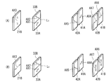
- the slow axis AX1 has the same direction as the direction of the slow axis AX4 of the right-eye phase difference plate 41A (described later) of the polarizing glasses 2 as shown in FIGS. 5 (A) and 5 (B), for example. It faces the direction different from the direction of the slow axis AX5 of the left-eye retardation plate 42A (described later) of the polarizing glasses 2.
- the slow axis AX2 is directed in the same direction as the slow axis AX5, for example, and is directed in a direction different from the slow axis AX4.
- the retardation layer 33 includes, for example, a polymerized polymer liquid crystal material. That is, in the retardation layer 33, the alignment state of the liquid crystal molecules is fixed.
- a polymerized polymer liquid crystal material a material selected according to a phase transition temperature (liquid crystal phase-isotropic phase), a refractive index wavelength dispersion characteristic, a viscosity characteristic, a process temperature, and the like of the liquid crystal material is used.
- the major axes of the liquid crystal molecules are arranged along the extending direction of the groove V1, and the groove V2 and the left-eye retardation are arranged.
- the major axes of the liquid crystal molecules are aligned along the extending direction of the groove V2. That is, the orientation of the liquid crystal molecules is controlled by the shapes and extending directions of the grooves V1 and V2, and the optical axes of the right-eye retardation region 33A and the left-eye retardation region 33B are set.
- the retardation values of the right-eye retardation region 33A and the left-eye retardation region 33B are set by adjusting the constituent materials and thicknesses of the right-eye retardation region 33A and the left-eye retardation region 33B. Is done.
- This retardation value is preferably set in consideration of the phase difference of the base material 31 when the base material 31 has a phase difference.
- the right-eye retardation region 33A and the left-eye retardation region 33B are made of the same material and thickness, and thereby the absolute values of the retardations are equal to each other.
- the polarized glasses 2 are worn in front of the eyeball of an observer (not shown), and are used by the observer when observing an image displayed on the image display surface 1A of the display device 1.
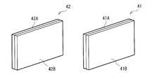
- the polarized glasses 2 are, for example, circularly polarized glasses, and include, for example, a right-eye optical element 41, a left-eye optical element 42, and a frame 43 as shown in FIG.
- the frame 43 supports the right-eye optical element 41 and the left-eye optical element 42.
- the shape of the frame 43 is not particularly limited.
- the frame 43 has a shape that is caught on the nose and ears of an observer (not shown).
- the right-eye optical element 41 and the left-eye optical element 42 are used in a state of facing the video display surface 1 ⁇ / b> A of the display device 1.
- the right-eye optical element 41 and the left-eye optical element 42 are preferably used in a state where they are arranged in one horizontal plane as much as possible, but are used in a state where they are arranged in a slightly inclined flat surface. May be.
- the right-eye optical element 41 includes, for example, a right-eye retardation plate 41A and a polarizing plate 41B as shown in FIG.
- the right-eye retardation plate 41A and the polarizing plate 41B are sequentially arranged from the display device 1 side.
- the left-eye optical element 42 includes, for example, a left-eye retardation plate 42A and a polarizing plate 42B as shown in FIG.
- the left-eye retardation plate 42A and the polarizing plate 42B are sequentially arranged from the display device 1 side.
- the right-eye optical element 41 and the left-eye optical element 42 may have members other than those exemplified above. For example, when the polarizing plates 41B and 42B are damaged on the light emitting side (observer side) surfaces of the right-eye optical element 41 and the left-eye optical element 42, the broken pieces are prevented from scattering on the eyeball of the observer. A protective film (not shown) or a protective coating layer (not shown) may be provided. Further, the right-eye optical element 41 and the left-eye optical element 42 may have, for example, a flat plate shape as shown in FIG. 6 or a curved shape protruding toward the light incident side, although not shown. It may be a shape.
- the polarizing plates 41B and 42B pass only light (polarized light) in a certain vibration direction.
- the polarization axes AX6 and AX7 of the polarizing plates 41B and 42B are oriented in the direction orthogonal to the polarization axis AX3 of the polarizing plate 21B of the display device 1, respectively.
- the polarization axes AX6 and AX7 are horizontally oriented when the polarization axis AX3 of the polarizing plate 21B is oriented vertically, for example, FIG.
- the right-eye retardation plate 41A and the left-eye retardation plate 42A are thin layers or films having optical anisotropy.
- the slow axis AX4 of the right-eye phase difference plate 41A faces the direction intersecting with the polarization axis AX6 at 45 °.
- the slow axis AX5 of the left-eye retardation plate 42A faces the direction intersecting with the polarization axis AX7 at 45 °
- the slow axis AX4 It faces the direction orthogonal to. For example, as shown in FIGS.
- the slow axes AX4 and AX5 are respectively in the horizontal and vertical directions when the polarization axes AX6 and AX7 are oriented in the horizontal direction or the vertical direction. It faces in the direction that intersects any of the directions.
- the slow axis AX4 is directed to the horizontal direction, for example, and the slow axis AX5 is directed to the vertical direction, for example.
- the slow axis AX4 is directed in the same direction as the slow axis AX1 of the right-eye phase difference area 33A, and is directed in a direction different from the direction of the slow axis AX2 of the left-eye phase difference area 33B.
- the slow axis AX5 is directed in the same direction as the slow axis AX2, and is directed in a direction different from the direction of the slow axis AX1.
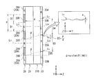
- FIG. 7 is an enlarged view of a part of the cross section of the liquid crystal display panel 20 and the phase difference element 30.
- a pixel 20 ⁇ / b> A that generates right-eye video light (a portion illustrated as R in the drawing) and a pixel 20 ⁇ / b> A that generates left-eye video light (a portion illustrated as L in the drawing).
- a black matrix portion 28B is provided between the right-eye pixel 20A and the left-eye pixel 20A adjacent to each other in a direction (vertical direction) orthogonal to the pixel row.
- a black matrix portion 28 ⁇ / b> B is provided between the adjacent right-eye pixels 20 ⁇ / b> A in a direction parallel to the pixel row (horizontal direction).
- the black matrix portion 28B is also provided between the left-eye pixels 20A adjacent to each other in the direction parallel to the pixel row (horizontal direction).
- a filter unit 28A is disposed on the video display surface 1A side of the right-eye pixel 20A, and this filter unit 28A functions as an opening of the right-eye pixel 20A.
- a filter unit 28A is also arranged on the video display surface 1A side of the left-eye pixel 20A, and this filter unit 28A functions as an opening of the left-eye pixel 20A.
- the vertical width D1 of each filter unit 28A and the distance D2 between the filter units 28A adjacent to each other in the vertical direction are equal to each other.
- the right-eye phase difference region 33A of the phase difference layer 33 includes a vertical center line Lc1 of the right-eye pixel 20A (filter unit 28A) and a vertical center line Lc2 of the right-eye phase difference region 33A. They are arranged in the same plane.
- the left-eye phase difference area 33B of the phase difference layer 33 includes a vertical center line Lc3 of the left-eye pixel 20A (filter unit 28A) and a vertical center line Lc4 of the left-eye phase difference area 33B. They are arranged so as to be in the same plane. Furthermore, the vertical width D3 of the right-eye retardation region 33A is equal to the pixel 20A pitch P, and the vertical width D4 of the left-eye retardation region 33B is also equal to the pixel 20A pitch P.
- the shift amount D5 between the boundary line Lb and the upper end of the pixel 20A and the distance d are the amount of leakage of the right-eye video light into the left-eye phase difference region 33B or the right-eye phase difference of the left-eye video light.
- the boundary line Lb has a wave of amplitude a that satisfies the following equations (1) to (3).
- amax ( ⁇ ) is the maximum value of the amplitude a when the worse value of two types of crosstalk defined by the following equations (4) and (5) is 5%.
- the following formulas (4) and (5) target the range of the vertical viewing angle ⁇ 5 degrees as the observation direction.
- Crosstalk of left-eye image light (luminance when left-eye image light is viewed through right-eye optical element 41 of polarized glasses 2) / (left-eye image light is converted to left-eye optical element 42 of polarized glasses 2) (Luminance when viewed through)
- Crosstalk of right-eye image light (luminance when right-eye image light is viewed through left-eye optical element 42 of polarized glasses 2) / (right-eye image light and right-eye optical element 41 of polarized glasses 2) (Luminance when viewed through) (5)
- the boundary line Lb is a straight line, but when actually observed with an optical microscope, the boundary line Lb is unexpectedly wavy.
- the waviness of the boundary line Lb tends to increase when the alignment film 32 is made of a photo-alignment film, and tends to decrease when the alignment film 32 is manufactured by a manufacturing method (mold transfer) described later.
- the boundary line of the photo-alignment film was measured with one of the display devices on the market, the undulation of the boundary line Lb was so large that the above formula was not satisfied.
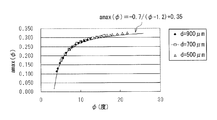
- FIG. 8 shows the relationship between the angle ⁇ and amax ( ⁇ ) obtained by simulation when the crosstalk is 5%.
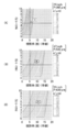
- FIG. 9 shows the relationship between the viewing angle and crosstalk obtained by simulation.
- 9A shows the results when the panel size is 23 inches and the pixel pitch is 265 ⁇ m
- FIG. 9B shows the results when the panel size is 47 inches and the pixel pitch is 542 ⁇ m
- FIG. 9C shows the panel size 55. This is the result when the pixel pitch is 630 ⁇ m.
- FIG. 9 shows a result when it is assumed that the pixel 20A and the phase difference element 30 have the relationship shown in FIG.
- FIG. 9 shows that the maximum value of the amplitude a that can suppress the crosstalk to 5% or less increases as the pixel pitch increases, that is, as the angle ⁇ increases.
- FIG. 9 shows that as the pixel pitch increases, the maximum value of the viewing angle at which crosstalk can be suppressed to 5% or less also increases.
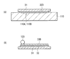
- FIGS. 10A and 10B show a process of manufacturing the phase difference element 30.
- FIG. First a plate in which a plurality of uneven regions 110A having an inverted pattern of surface unevenness of the right-eye alignment region 32A and a plurality of uneven regions 110B having an inverted pattern of surface unevenness of the left-eye alignment region 32B are alternately formed on the surface.
- a prepared master 110 is prepared.
- a UV curable resin layer 32D containing, for example, a UV curable acrylic resin liquid is disposed on the surface of the master 110, the UV curable resin layer 32D is sealed with the base material 31 (FIG. 10A).
- the UV curable resin layer 32D is cured by irradiating the UV curable resin layer 32D with ultraviolet rays.
- the alignment film 32 in which the right-eye alignment regions 32A and the left-eye alignment regions 32B are alternately arranged is formed on the base material 31. Thereafter, the master 110 is peeled off.
- a liquid crystal layer 33D containing a liquid crystal monomer is coated on the surface of the alignment film 32 by, for example, a roll coater 120 (FIG. 10B).
- a solvent for dissolving the liquid crystalline monomer, a polymerization initiator, a polymerization inhibitor, a surfactant, a leveling agent, and the like can be used for the liquid crystal layer 33D as necessary.
- it does not specifically limit as a solvent It is preferable to use the thing with the high solubility of a liquid crystalline monomer, low vapor pressure at room temperature, and being hard to evaporate at room temperature.
- Examples of the solvent that hardly evaporates at room temperature include 1-methoxy-2-acetoxypropane (PGMEA), toluene, methyl ethyl ketone (MEK), and methyl isobutyl ketone (MIBK). This is because if a solvent that easily evaporates at room temperature is used, the evaporation rate of the solvent after coating and forming the liquid crystal layer 33D is too high, and the alignment of the liquid crystalline monomer formed after the evaporation of the solvent tends to be disturbed. is there.
- PGMEA 1-methoxy-2-acetoxypropane
- MEK methyl ethyl ketone
- MIBK methyl isobutyl ketone
- alignment treatment of the liquid crystalline monomer of the liquid crystal layer 33D is performed.
- This heat treatment is performed at a temperature equal to or higher than the phase transition temperature of the liquid crystalline monomer, and particularly when a solvent is used, at a temperature equal to or higher than the temperature at which the solvent dries.
- the coating of the liquid crystalline monomer in the previous step causes a shear stress to act on the interface between the liquid crystalline monomer and the alignment film 32, thereby causing an alignment due to flow (fluid alignment) or an alignment due to force (external force alignment). It may be oriented in an unintended direction.
- the heat treatment is performed in order to temporarily cancel the alignment state of the liquid crystalline monomer that has been aligned in such an unintended direction.
- the solvent is dried to become only the liquid crystalline monomer, and the state thereof is an isotropic phase.
- the liquid crystal layer 33D is gradually cooled to a temperature slightly lower than the phase transition temperature.
- the liquid crystalline monomer is aligned according to the pattern of the alignment region 32A for the right eye and the alignment region 32B for the left eye formed on the surface of the alignment film 32. That is, the liquid crystalline monomer is aligned along the extending direction of the grooves V1 and V2.
- the liquid crystalline monomer is polymerized by irradiating the liquid crystal layer 33D after the alignment treatment with, for example, UV light.
- the treatment temperature is generally around room temperature, but the temperature may be raised to a temperature equal to or lower than the phase transition temperature in order to adjust the retardation value.
- the alignment state of the liquid crystal molecules is fixed along the extending direction of the grooves V1 and V2, and the right-eye retardation region 33A and the left-eye retardation region 33B are formed.
- the phase difference element 30 is completed.
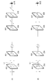
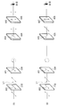
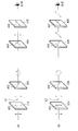
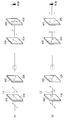
- FIGS. 11A and 11B and FIGS. 12A and 12B focus only on the right-eye image light L1 incident on the right-eye retardation region 33A of the retardation layer 33, and pass through the polarizing glasses 2.
- the right-eye image light L1 and the left-eye image light L2 are output in a mixed state.
- FIGS. 11A and 11B FIGS. 14A and 14B are described.
- the image light L1 for the right eye and the image light L2 for the left eye are separately described.
- a parallax signal including a right-eye image and a left-eye image is input to the liquid crystal display panel 20 as a video signal. Then, the right-eye image light L1 is output from the odd-numbered pixels (FIGS. 11A and 11B or FIGS. 12A and 12B), and the left-eye image light L2 is output from the even-numbered pixels. (FIGS. 13A and 13B or FIGS. 14A and 14B).
- the right-eye image light L1 and the left-eye image light L2 are converted into elliptically polarized light by the right-eye phase difference region 33A and the left-eye phase difference region 33B of the phase difference element 30, and then the video display surface 1A of the display device 1 is displayed. Is output to the outside. Thereafter, the light output to the outside of the display device 1 is incident on the polarizing glasses 2 and is returned from elliptically polarized light to linearly polarized light by the right-eye phase difference plate 41A and the left-eye phase difference plate 42A. 42B is incident.
- the polarization axis of the light corresponding to the right-eye image light L1 among the incident light to the polarization plates 41B and 42B is parallel to the polarization axis AX6 of the polarization plate 41B, and the polarization axis AX7 of the polarization plate 42B. Orthogonal. Accordingly, the light corresponding to the right-eye image light L1 among the incident light to the polarizing plates 41B and 42B is transmitted only through the polarizing plate 41B and reaches the right eye of the observer (FIGS. 11A and 11B). Or FIG. 12 (A), (B)).
- the polarization axis of the light corresponding to the image light L2 for the left eye among the incident lights to the polarization plates 41B and 42B is orthogonal to the polarization axis AX6 of the polarization plate 41B and parallel to the polarization axis AX7 of the polarization plate 42B. It has become. Therefore, the light corresponding to the image light L2 for the left eye among the incident light to the polarizing plates 41B and 42B is transmitted only through the polarizing plate 42B and reaches the left eye of the observer (FIGS. 13A and 13B). Or FIG. 14 (A), (B)).
- the observer can view the image of the display device 1. It can be recognized as if a stereoscopic image is displayed on the display surface 1A.
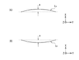
- the boundary line Lb between the right-eye retardation region 33A and the left-eye retardation region 33B is expressed by the above equations (1) to (3). It has a wave of amplitude a to satisfy.
- the ratio of the right-eye image light entering the left-eye phase difference region 33B due to the undulation of the boundary line Lb, and vice versa the ratio of the left-eye image light entering the right-eye phase difference region 33A.
- the ratio can be reduced. As a result, it is possible to reduce crosstalk degradation.
- the boundary line Lb is exemplified as a regular or periodic undulation, but may be an irregular undulation, for example, as shown in FIG. ), (B), the upper or lower side may be bent like a bow.
- phase difference regions (the right-eye phase difference region 33A and the left-eye phase difference region 33B) of the phase difference element 30 extend in the horizontal direction. It does not matter if it extends in the direction of.
- the phase difference regions (the right-eye phase difference region 33A and the left-eye phase difference region 33B) of the phase difference element 30 may extend in the vertical direction.
- phase difference regions of the phase difference element 30 there are only two types of phase difference regions of the phase difference element 30, but there may be three or more types.
- the polarized glasses 2 are of the circularly polarized type and the display device 1 is a display device for circularly polarized glasses has been described.
- the polarized glasses 2 are of the linearly polarized type and display
- the present technology can also be applied to the case where the device 1 is a display device for linearly polarized glasses.
- each is substantially equal to the extent that the effect of the present technology is not impaired.
- an error caused by various factors such as manufacturing error and variation may be included.
- this technique can take the following composition.
- a display panel in which a plurality of pixels are arranged in a matrix;
- a retardation element bonded to the display panel,
- the phase difference element has a phase difference layer in which two or more types of phase difference regions different from each other in the direction of the slow axis are arranged corresponding to each pixel, Each phase difference region is arranged in contact with other types of phase difference regions,
- the side part which touches other kinds of phase contrast fields among each phase contrast field has a wave of amplitude a which satisfies the following formula.
- the display panel has a light transmissive filter portion on the phase difference element side of each pixel, Furthermore, it has a black matrix part in the same plane as the filter part,
- variety of each filter part and the distance between mutually adjacent filter parts are mutually equal, The display apparatus as described in (B).
Landscapes
- Physics & Mathematics (AREA)
- General Physics & Mathematics (AREA)
- Optics & Photonics (AREA)
- Chemical & Material Sciences (AREA)
- Crystallography & Structural Chemistry (AREA)
- Nonlinear Science (AREA)
- Mathematical Physics (AREA)
- Liquid Crystal (AREA)
- Polarising Elements (AREA)
Priority Applications (3)
| Application Number | Priority Date | Filing Date | Title |
|---|---|---|---|
| CN201280037465.3A CN103718072A (zh) | 2011-08-03 | 2012-07-30 | 显示装置 |
| US14/235,376 US9164322B2 (en) | 2011-08-03 | 2012-07-30 | Display unit |
| IN631CHN2014 IN2014CN00631A (enExample) | 2011-08-03 | 2012-07-30 |
Applications Claiming Priority (2)
| Application Number | Priority Date | Filing Date | Title |
|---|---|---|---|
| JP2011170008A JP2013033175A (ja) | 2011-08-03 | 2011-08-03 | 表示装置 |
| JP2011-170008 | 2011-08-03 |
Publications (1)
| Publication Number | Publication Date |
|---|---|
| WO2013018750A1 true WO2013018750A1 (ja) | 2013-02-07 |
Family
ID=47629273
Family Applications (1)
| Application Number | Title | Priority Date | Filing Date |
|---|---|---|---|
| PCT/JP2012/069299 Ceased WO2013018750A1 (ja) | 2011-08-03 | 2012-07-30 | 表示装置 |
Country Status (5)
| Country | Link |
|---|---|
| US (1) | US9164322B2 (enExample) |
| JP (1) | JP2013033175A (enExample) |
| CN (1) | CN103718072A (enExample) |
| IN (1) | IN2014CN00631A (enExample) |
| WO (1) | WO2013018750A1 (enExample) |
Cited By (1)
| Publication number | Priority date | Publication date | Assignee | Title |
|---|---|---|---|---|
| TWI852945B (zh) * | 2018-09-26 | 2024-08-21 | 日商東京威力科創股份有限公司 | 電漿處理裝置 |
Families Citing this family (4)
| Publication number | Priority date | Publication date | Assignee | Title |
|---|---|---|---|---|
| CN110959132B (zh) * | 2017-05-27 | 2022-06-14 | 李汶基 | 眼镜型显示器及可变焦距眼镜型显示器 |
| CN108051926B (zh) | 2018-01-02 | 2021-04-30 | 京东方科技集团股份有限公司 | 一种显示面板、可穿戴vr显示装置 |
| CN110221375B (zh) * | 2018-03-02 | 2022-08-02 | 住友化学株式会社 | 层叠膜 |
| CN110133864A (zh) * | 2019-05-30 | 2019-08-16 | 京东方科技集团股份有限公司 | 立体显示装置及其制造方法 |
Citations (1)
| Publication number | Priority date | Publication date | Assignee | Title |
|---|---|---|---|---|
| JP2010164956A (ja) * | 2008-12-15 | 2010-07-29 | Sony Corp | 位相差素子および表示装置 |
Family Cites Families (5)
| Publication number | Priority date | Publication date | Assignee | Title |
|---|---|---|---|---|
| US3881706A (en) | 1973-06-28 | 1975-05-06 | William C Mohrmann | Trailer having concrete mixer thereon |
| US5327285A (en) | 1990-06-11 | 1994-07-05 | Faris Sadeg M | Methods for manufacturing micropolarizers |
| US5676975A (en) | 1995-06-29 | 1997-10-14 | Dezes; Alexander C. | Burn symptom relief composition and method of producing same |
| JP4027898B2 (ja) * | 2004-01-29 | 2007-12-26 | 株式会社有沢製作所 | 偏光透過スクリーン、及び当該偏光透過スクリーンを用いた立体画像表示装置 |
| TW200842417A (en) * | 2006-12-28 | 2008-11-01 | Sony Corp | Optical compensation plate, liquid crystal display device, projection type liquid crystal display device, display device manufacturing method, and adjusting method |
-
2011
- 2011-08-03 JP JP2011170008A patent/JP2013033175A/ja not_active Withdrawn
-
2012
- 2012-07-30 CN CN201280037465.3A patent/CN103718072A/zh active Pending
- 2012-07-30 US US14/235,376 patent/US9164322B2/en active Active
- 2012-07-30 IN IN631CHN2014 patent/IN2014CN00631A/en unknown
- 2012-07-30 WO PCT/JP2012/069299 patent/WO2013018750A1/ja not_active Ceased
Patent Citations (1)
| Publication number | Priority date | Publication date | Assignee | Title |
|---|---|---|---|---|
| JP2010164956A (ja) * | 2008-12-15 | 2010-07-29 | Sony Corp | 位相差素子および表示装置 |
Cited By (1)
| Publication number | Priority date | Publication date | Assignee | Title |
|---|---|---|---|---|
| TWI852945B (zh) * | 2018-09-26 | 2024-08-21 | 日商東京威力科創股份有限公司 | 電漿處理裝置 |
Also Published As
| Publication number | Publication date |
|---|---|
| US20140192303A1 (en) | 2014-07-10 |
| JP2013033175A (ja) | 2013-02-14 |
| US9164322B2 (en) | 2015-10-20 |
| CN103718072A (zh) | 2014-04-09 |
| IN2014CN00631A (enExample) | 2015-04-03 |
Similar Documents
| Publication | Publication Date | Title |
|---|---|---|
| JP5445761B2 (ja) | 位相差素子および表示装置 | |
| CN101896842B (zh) | 相差元件和显示设备 | |
| JP5055406B2 (ja) | 位相差素子および表示装置 | |
| US10564337B2 (en) | Optical film | |
| WO2013018750A1 (ja) | 表示装置 | |
| WO2010110432A1 (ja) | 液晶表示装置 | |
| US9259906B2 (en) | Optical laminated body, method of manufacturing the same, and display unit | |
| JP5828204B2 (ja) | 塗料、位相差素子、表示装置、位相差素子の製造方法 | |
| CN102289019A (zh) | 立体影像观看光学元件和眼镜、以及立体影像显示系统 | |
| US20130052341A1 (en) | Alignment film and method of manufacturing the alignment film, and retardation film and method of manufacturing the retardation film | |
| CN105334564B (zh) | 滤光片 | |
| JP2013101262A (ja) | 積層体およびその製造方法、ならびに表示装置 | |
| JP5711071B2 (ja) | 積層体、低反射性積層体、偏光板、画像表示装置、及び3d画像表示システム | |
| KR20140137511A (ko) | 영상표시장치 | |
| JP2017199032A (ja) | 配向フィルムおよびその製造方法、ならびに位相差フィルムおよびその製造方法 | |
| JP2016085474A (ja) | 配向フィルムおよびその製造方法、ならびに位相差フィルムおよびその製造方法 |
Legal Events
| Date | Code | Title | Description |
|---|---|---|---|
| 121 | Ep: the epo has been informed by wipo that ep was designated in this application |
Ref document number: 12819756 Country of ref document: EP Kind code of ref document: A1 |
|
| WWE | Wipo information: entry into national phase |
Ref document number: 14235376 Country of ref document: US |
|
| NENP | Non-entry into the national phase |
Ref country code: DE |
|
| 122 | Ep: pct application non-entry in european phase |
Ref document number: 12819756 Country of ref document: EP Kind code of ref document: A1 |