WO2013018141A1 - Dispositif d'alimentation électrique, dispositif de transmission audio, système de haut-parleurs, haut-parleur, procédé de commande de dispositif d'alimentation électrique et programme - Google Patents
Dispositif d'alimentation électrique, dispositif de transmission audio, système de haut-parleurs, haut-parleur, procédé de commande de dispositif d'alimentation électrique et programme Download PDFInfo
- Publication number
- WO2013018141A1 WO2013018141A1 PCT/JP2011/004385 JP2011004385W WO2013018141A1 WO 2013018141 A1 WO2013018141 A1 WO 2013018141A1 JP 2011004385 W JP2011004385 W JP 2011004385W WO 2013018141 A1 WO2013018141 A1 WO 2013018141A1
- Authority
- WO
- WIPO (PCT)
- Prior art keywords
- speaker
- data
- charging
- audio
- speakers
- Prior art date
Links
Images


Classifications
-
- H—ELECTRICITY
- H02—GENERATION; CONVERSION OR DISTRIBUTION OF ELECTRIC POWER
- H02J—CIRCUIT ARRANGEMENTS OR SYSTEMS FOR SUPPLYING OR DISTRIBUTING ELECTRIC POWER; SYSTEMS FOR STORING ELECTRIC ENERGY
- H02J7/00—Circuit arrangements for charging or depolarising batteries or for supplying loads from batteries
- H02J7/0013—Circuit arrangements for charging or depolarising batteries or for supplying loads from batteries acting upon several batteries simultaneously or sequentially
- H02J7/0014—Circuits for equalisation of charge between batteries
- H02J7/0019—Circuits for equalisation of charge between batteries using switched or multiplexed charge circuits
-
- H—ELECTRICITY
- H04—ELECTRIC COMMUNICATION TECHNIQUE
- H04R—LOUDSPEAKERS, MICROPHONES, GRAMOPHONE PICK-UPS OR LIKE ACOUSTIC ELECTROMECHANICAL TRANSDUCERS; DEAF-AID SETS; PUBLIC ADDRESS SYSTEMS
- H04R27/00—Public address systems
-
- H—ELECTRICITY
- H04—ELECTRIC COMMUNICATION TECHNIQUE
- H04R—LOUDSPEAKERS, MICROPHONES, GRAMOPHONE PICK-UPS OR LIKE ACOUSTIC ELECTROMECHANICAL TRANSDUCERS; DEAF-AID SETS; PUBLIC ADDRESS SYSTEMS
- H04R2227/00—Details of public address [PA] systems covered by H04R27/00 but not provided for in any of its subgroups
- H04R2227/005—Audio distribution systems for home, i.e. multi-room use
Definitions
- the present invention relates to a power supply apparatus, an audio transmission apparatus, a speaker system, a speaker, a control method for a power supply apparatus, and a program for supplying power to a plurality of speakers connected in series via a single transmission path.
- a power supply apparatus an audio transmission apparatus, a speaker system, a speaker, a control method for a power supply apparatus, and a program for supplying power to a plurality of speakers connected in series via a single transmission path.
- Patent Document 1 has been proposed as a method of supplying power to each speaker connected in a daisy chain (series connection by a single transmission line, daisy chain connection).
- each speaker is provided with a first connector that receives power supply from an AC power source and a second connector that receives power supply via a transmission line, and is supplied from any one of the connectors.
- a configuration using power determined to have a high power voltage value is described.
- the speaker described in Patent Document 1 can adaptively select a power supply source used internally, and can perform a stable operation as a whole system.
- the present invention provides a power supply device, an audio transmission device, a speaker system, a speaker, and the like that can stably supply power to each daisy chain connected speaker using only one transmission line. It is an object to provide a control method and program for a power supply apparatus.
- the power supply device of the present invention is a power supply device that supplies power to a plurality of speakers connected in series via one transmission line via the transmission line, and charges the secondary batteries of the plurality of speakers. And a charge control unit that controls charging of each speaker by switching, in a time division manner, a target speaker that is designated as a charging target among a plurality of speakers.
- a control method for a power supply apparatus of the present invention is a control method for a power supply apparatus that supplies power via a transmission line to secondary batteries of a plurality of speakers connected in series via a single transmission line,
- the power supply device performs a charge control step of controlling charging to each speaker by switching a target speaker to be specified as a charging target among a plurality of speakers in a time division manner.
- the power supply device side performs control to switch the target speaker designated as the charging target in a time-sharing manner, thereby stably supplying power to each speaker using only one transmission line. be able to.
- power supply is not performed randomly, and the problem of allowable current capacity and the problem of voltage drop and heat generation due to the impedance of the power supply line can be solved.
- switching target speakers in a time-sharing manner means that the target speakers are sequentially switched every predetermined time.
- the number of target speakers is not necessarily one, and a plurality of target speakers may be provided as long as stable power supply can be performed.
- An audio transmission apparatus includes each unit in the above-described power supply apparatus and an audio transmission unit that transmits audio data to a plurality of speakers via a transmission path, and the audio transmission unit is a transmission target. Audio data is transmitted together with a speaker ID for designating a speaker.
- both power supply and audio data transmission can be realized by connecting each speaker with only one transmission path.
- the number of transmission paths can be suppressed, and the system configuration can be simplified and reduced in price.
- wiring work is facilitated, and there is no hindrance during passage and cleaning.
- the target speaker is preferably specified by transmitting the speaker ID via the transmission path. According to this configuration, the target speaker can be easily and reliably switched.
- the transmission path is a general-purpose cable.
- a LAN cable that uses a general-purpose cable can be used, so that the system configuration can be further reduced in price.
- the general-purpose cable is a multi-core cable capable of transmitting signals, control, and power.
- a speaker system includes the above-described audio transmission device and a plurality of speakers, and each speaker maintains a secondary battery charging stop state when the speaker is not designated as a target speaker. .
- the charging control unit counts the elapsed time from the start of charging the target speaker, and when the predetermined time has elapsed, determines that charging is complete and switches the target speaker.
- each speaker detects a remaining amount detecting unit for detecting the remaining amount of its secondary battery, and when the remaining amount of the secondary battery exceeds a first predetermined amount during charging.
- a charge stop request transmission unit that transmits a charge stop request to the audio transmission device, and when the charge control unit receives the charge stop request from the speaker that is being charged, determines that charging is complete, and the target speaker It is characterized by switching.
- the transmission device further includes a charge start request transmission unit that transmits a charge start request, and when the charge control unit receives a charge start request from a non-charged speaker, the charging to the speaker being charged is stopped, Alternatively, after the charging of the speaker being charged is completed, the speaker that has requested charging start is switched to the target speaker.
- the speaker when a charging start request is received from a non-charging speaker, the speaker is set as the next target speaker, so that insufficient charging can be prevented. As a result, a stable audio output can be performed as a speaker system.
- the speaker of the present invention is used in the above speaker system.
- the program of the present invention causes a computer to execute each step in the above-described method for controlling the power supply apparatus.
- FIG. 1 is a system configuration diagram of a speaker system according to an embodiment of the present invention. It is a figure which shows the example of arrangement
- FIG. 1 is a system configuration diagram of the speaker system SY.
- the speaker system SY includes an audio transmission device 1 that functions as an AV center unit (AV receiver), a plurality of speakers 2, and a daisy chain cable 3 (transmission) for connecting the speakers 2 in series. Path, hereinafter simply referred to as “cable 3”) and an audio input source 4 for inputting audio data.
- AV center unit AV receiver
- daisy chain cable 3 transmission
- path hereinafter simply referred to as “cable 3”
- an audio input source 4 for inputting audio data.
- the audio input source 4 is wired / wirelessly connected to the audio transmission device 1 and mainly uses content via a network (including streaming playback), a CD player, a Blu-ray player, a smartphone, a network player, and the like.
- the audio transmission device 1 incorporates a decoder 41 (see FIG. 16 and the like) corresponding to each audio input source 4, and multi-channel audio data input from each audio input source 4 is transmitted via the cable 3 to each Transmit to the speaker 2.
- a cable 3 in which audio data of each channel is packed is serially transmitted.
- the audio transmission device 1 also functions as a power supply device, and supplies power to each speaker 2 via the cable 3. The supply of power will be described in the fourth embodiment.
- As the cable 3, a general-purpose cable or the like (see FIG. 32) is used.
- the speaker 2 has a built-in amplifier 56 (sound amplifier function, see FIG. 18 and the like), and volume control and channel selection designation are performed using the control line of the cable 3.
- a plurality of speakers 2 are connected in series via one cable 3 (physically, the number of speakers 3 connecting between the speakers 2), and are arranged at home or in a hall.
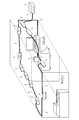
- FIG. 2 is a diagram illustrating an arrangement example of the speakers 2 when the speaker system SY is constructed in two rooms at home. In the example of the figure, a total of 12 speakers are arranged in the order of a part of speakers 2 arranged in the living room from the audio transmission device 1, a speaker 2 arranged in the kitchen, and the remaining speakers 2 arranged in the living room. Are connected in a daisy chain.
- the speaker system SY of this embodiment can introduce the speaker system SY across a plurality of rooms. Therefore, by installing only one audio transmission apparatus 1 at home, different contents can be reproduced simultaneously in a plurality of zones (reproduction areas).
- the audio transmission device 1 is connected to a plurality of audio input sources 4 as described above, and can simultaneously reproduce audio data input from the audio input sources 4. Accordingly, it is possible to enjoy the music of the CD player in the living room and the music of the Blu-ray player in the kitchen.
- the speaker system SY in the home it is not necessary to arrange the audio transmission device 1 for each room, and the number of cables can be reduced, so that an audio viewing environment can be simply constructed.
- the number of cables can be reduced significantly and the problem that the cable 3 becomes obstructive at the time of cleaning etc. can also be eliminated. .
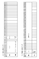
- FIG. 3A is a rear view of the audio transmission device 1.
- a power supply port 11 that receives power supply from an AC power supply and one output terminal 12 for performing daisy chain output are provided.
- the output terminal 12 has a simple configuration, thereby reducing the size of the housing. Can do.
- FIG. 3B is a front view and a rear view of the speaker 2.
- a vibration member 21 is provided on the front surface of the speaker 2.
- one input terminal 22 and one output terminal 23 for performing daisy chain input / output are provided.
- the rear configuration of all speakers 2 connected in a daisy chain is the same.
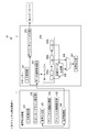
- the audio transmission device 1 includes an ID initialization unit 101, a speaker assignment setting unit 102, an audio input unit 103, a channel information acquisition unit 104, a channel information setting unit 105, and a transmission control unit 106 as main functional configurations.
- the ID initialization unit 101 performs initial setting for recognizing the configuration of the speakers 2 connected in a daisy chain.
- the ID initialization unit 101 issues a unique speaker ID to each speaker 2 and stores the issued speaker ID in an internal memory (not shown) according to the issue order. Details will be described later with reference to FIG.
- the speaker assignment setting unit 102 performs assignment processing that prompts the user to assign a channel to the speaker 2.
- the audio transmission device 1 is provided with a display and a user interface such as an operation panel or a remote controller.
- the corresponding speaker 2 can be assigned to each zone (multi-listening area). Details will be described later with reference to FIGS.
- the voice input unit 103 inputs voice data (audio sampling data) from each voice input source 4. It is also possible to input a plurality of channels of audio data from each audio input source 4.
- the channel information acquisition unit 104 acquires it.
- the channel information is information indicating the number of content reproduction channels and channels to be thinned / not thinned.
- the audio data to be transmitted to each speaker 2 is thinned out in the time axis direction, thereby realizing audio reproduction with an increased number of allowable transmission channels than before without increasing the transmission frequency.
- the “channel to be thinned out” is set to, for example, “fourth to thirteenth channels” when 13 channels are realized. In this case, the fourth to thirteenth total 10 channels are divided into two groups of fourth to eighth and ninth to thirteenth, and audio data is transmitted alternately. As a result, 13-channel content reproduction is realized with a data transmission amount for a maximum of 8 channels.
- the channel information setting unit 105 sets channel information (thinning target / non-thinning target channel) using a user interface provided in the audio transmission device 1.
- the channel information acquired by the channel information acquisition unit 104 may be prioritized.
- the user may be able to set which is prioritized, or may be configured to prompt the user to set channel information only when channel information is not embedded in the playback content. In the latter case, the following setting method can be considered.
- the audio transmission device 1 determines whether division transmission is necessary by comparing with the number of reproduction channels included in the content.
- the user is prompted to select the speaker 2 that is not desired to be divided or the speaker 2 that may be divided.
- the audio transmission device 1 determines whether or not the transmission rate is within the allowable transmission rate (the number of speakers 2 to be divided is the necessary number that can be transmitted).
- the user is notified of the completion of the divided transmission setting.
- the user can set the viewing environment suitable for the viewing environment by setting the channel information.
- the transmission control unit 106 packs a plurality of audio data input from the plurality of audio input sources 4 into one frame for transmission.
- FIG. 12 shows a case where the audio data of channels 1 to 8 is 1 frame, and channels 1 to 3 and 9 to 13 are 1 frame, and each frame configuration is transmitted alternately. Specifically, at least a part of the plurality of speakers 2 connected in a daisy chain is divided into two speaker groups, and the audio data is divided into two pieces of sampling for each divided speaker group. Are transmitted sequentially (intermittent transmission control is performed). For example, in FIG. 12, channels 4 to 8 are grouped as a first group, and channels 9 to 13 are grouped as a second group.
- Channels 1 to 3 belong to non-divided groups that are not grouped. Audio data is always transmitted to the speakers 2 of these non-divided groups. In this non-divided group, relatively important speakers such as front L, R, and center channel, which are easy for the user to feel a difference in quality, are set.
- the speaker 2 includes an ID storage unit 201, a data selection acquisition unit 202, a daisy chain output unit 203, a data buffer 204, an interpolation data generation unit 205, a selection circuit 206, and an audio output unit 207 as main control configurations. Yes.
- the ID storage unit 201 stores the speaker ID issued by the ID initialization unit 101, and is realized by a nonvolatile memory.
- the data selection / acquisition unit 202 selects and acquires a start code packet and audio data for the own speaker 2 from the frame transmitted from the audio transmission device 1. Whether the speaker 2 is used is determined by using the speaker ID stored in the ID storage unit 201.
- the daisy chain output unit 203 performs daisy output to the next-stage speaker 2 connected downstream. That is, the frame transmitted from the upstream cable 3 is output to the downstream cable 3.
- the data buffer 204 stores audio data for three consecutive samples in the partial buffers 204a, 204b, and 204c.
- the interpolation data generation unit 205 adds the real data (actually transmitted audio data) stored in the preceding and subsequent partial buffers 204a and 204c, for example. Interpolation data is generated by halving.
- the interpolation data generation unit 205 determines the lack of data based on the channel setting flag included in the start code packet of the frame. That is, when the channel setting flag indicates “invalid”, it is determined that the audio data at that timing is missing, and interpolation data is generated.
- the selection circuit 206 selects whether to select interpolation data or real data according to the channel setting flag. When the channel setting flag indicates “invalid”, the interpolation data is selected. When the channel setting flag indicates “valid”, the real data stored in the data buffer 204 is selected.
- the audio output unit 207 outputs real data or interpolation data based on the selection result of the selection circuit 206. In the case of the present embodiment (when transmission is performed by dividing into two groups), the speaker 2 to be divided alternately outputs real data and interpolation data.
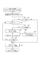
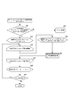
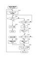
- the audio transmission device 1 accesses the head speaker 2 (the most upstream speaker 2) (S12).
- the ID storage unit 201 of the speaker 2 is cleared (S14), and a speaker ID is assigned (S15).
- daisy-out active setting is performed for the speaker 2 (S16), and the next (downstream) speaker 2 is accessed (S17).
- S18: Yes the steps after S14 are repeated.
- the audio transmission device 1 accesses the head speaker 2 (S31) and waits for reception of an ACK signal.
- the ACK signal is received (S32: Yes)
- the speaker ID of the speaker 2 is acquired (S33), and it is determined whether or not the value is an expected value (S34). That is, it is determined whether or not the speaker IDs are acquired in the stored order. If the speaker ID is not the expected value (S34: No), there is a possibility that the speaker 2 has been replaced or the order has been changed, so the daisy chain ID initialization process shown in FIG. 5 is performed ( S35).
- FIG. 7A is a flowchart showing the zone number setting process.
- the voice transmission device 1 first prompts the user to input the number of zones (S41). Specifically, the user is notified that input is required by display on the display or audio output. If the number of zones is input (S42: Yes), it is determined whether or not the value is valid (S43). If it is valid (S43: Yes), the set value is stored in the internal memory. Store (S44). If S42: No, input standby is performed, and if a time-out occurs (S45: Yes), error processing is performed (S46). If the time has not expired (S45: No), the process returns to S42. Furthermore, when the input zone number is an invalid value (S43: No), error processing is performed (S46).
- FIG. 7B is a flowchart showing the setting process of the number of channels (number of speakers 2).
- the user is prompted to input the number of channels (S51). In this case as well, the user is notified that input is required by display on the display or audio output.
- the number of channels is input (S52: Yes)
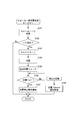
- FIG. 8 is a flowchart showing the speaker assignment setting process. This processing is assumed to be performed after the setting processing of FIGS. 7 (a) and 7 (b).
- the audio transmission device 1 determines whether or not there is a speaker 2 with an ID set and an unassigned setting (S61). If it does not exist (S61: No), error processing is performed (S62). If there is a speaker 2 with an ID set and no assignment (S61: Yes), the speaker ID to be set (initially “1”) is set (S63), and the assignment loop process is started sequentially (S63). S64).
- an identification signal (sound or indicator (LED)) is output from the speaker 2 to be set (S65), and the user is made aware of where to set the speaker 2 currently arranged.
- the user is prompted to input an assignment (S66).
- a zone number is input using a GUI on a display device (such as a TV monitor) connected to the audio transmission device 1.
- the generation of the identification signal is performed by the identification signal Gen67 (see FIG. 28).
- the speaker ID to be set is incremented (S74). If the ID is valid (S75: Yes if assignment of all speakers 2 has not been completed), S64 and thereafter. repeat. If the ID is invalid (when assignment of all speakers 2 is completed, S75: No), the speaker assignment setting process is terminated.
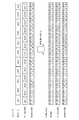
- data transmission is performed using three signals as shown in FIG.
- data of a plurality of channels is collected and data transmission is performed as one frame.
- data of up to 32 bits for each channel is embedded between Sync_data (start code packet) and Sync_data.
- Each channel is separated by a ch_div signal.
- the speaker 2 corresponding to each channel captures the data of each channel every frame, measures the synchronization timing with Sync_data, and takes the synchronization timing with clk.
- Sync_data is detected by determining a specific pattern in advance (see FIG. 15A, etc.).
- the data protocol of the figure is an example, and other data protocols may be used.
- the bit length is also arbitrary, and data such as 48, 64 bits may be embedded.
- voice (audio) data serial transmission will be described with reference to FIG.
- “S” indicates Sync_data, and each number indicates a channel number.
- the audio data (Nomal_data) of each channel is transmitted in time series.
- audio data for all channels (8 channels in the example in the figure) has been transmitted for all channels until the next Sync_data is sent (within 1 / fs). There is a need to.
- each speaker 2 is driven in synchronization, so that sound field reproduction can be performed for each moment (in sampling frequency units).
- FIG. 11 is an explanatory diagram of a channel setting flag.
- the Sync_data includes a payload and a channel setting flag.
- the payload includes various types of data information that follows.
- the channel setting flag indicates validity / invalidity for each channel (speaker 2).
- the setting (incorporation) of the channel setting flag is performed by the transmission control unit 106.
- Speaker 2 (interpolation data generation unit 205) recognizes transmission data according to the setting of the channel setting flag and determines that interpolation is necessary (when the channel setting flag for the speaker 2 indicates “invalid”). Generate interpolation data.
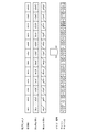
- FIG. 12 is a conceptual diagram of audio data serial transmission according to the present embodiment.
- data transmission is intermittently performed for some channels.
- channels 4 to 8 are divided into a first group and channels 9 to 13 are divided into a second group, and data transmission is performed alternately for each group.
- Channels 1 to 3 belong to a non-divided group that is not a grouping target (intermittent transmission target).
- the non-divided group + first group data is transmitted as an odd-numbered frame
- the non-divided group + second group data is transmitted as an even-numbered frame.
- each channel of the non-divided group and the second group reproduces real data that is audio data transmitted as a frame.
- each channel (channels 4 to 8) of the first group is obtained by multiplying, for example, the audio data transmitted in the first frame and the audio data transmitted in the third frame by a factor of 1/2. Interpolated data is generated and output in synchronization with the audio output timing of the second frame.
- each channel of the non-divided group and the first group reproduces real data.
- each channel (channels 9 to 13) of the second group is obtained by multiplying, for example, the audio data transmitted in the second frame and the audio data transmitted in the fourth frame by a factor of 1/2.
- Interpolated data is generated and output in synchronization with the audio output timing of the third frame. By repeating this, only 8 channels are always transmitted when viewed in units of frames. However, in the first group and the second group, real data and interpolated data are alternately output to constantly reproduce all 13 channels. Is possible.
- FIG. 13 is a flowchart showing the reproduction processing according to the present embodiment.
- the audio transmission apparatus 1 side data is alternately transmitted to each speaker group to be divided, and on the speaker 2 side, on the time axis acquired by the own speaker 2. Since interpolated data for interpolating untransmitted audio data is generated from the audio data before and after the above, the number of reproducible speakers (number of channels) can be increased without increasing the carrier frequency. Further, since it is not a method of generating interpolated data of the speaker 2 between the sampling data of the adjacent speakers 2, the sound field can be obtained even when a plurality of music reproductions are performed or when the correlation between adjacent channels is low. Thus, it is possible to transmit audio data for a number of channels while maintaining a sense of localization. In addition, it is possible to create multi-channel content that exceeds the upper limit on the number of channels determined by the standards of disk media and the like, and it is possible to meet the demand of content creators to express with more channels.
- the channel setting flag indicating validity / invalidity is defined for each speaker 2 in Sync_data, it is possible to accurately determine whether interpolation data should be generated on the speaker 2 side.
- a non-divided group that constantly transmits sampling data can be set, it is possible to prevent deterioration in sound quality.
- speakers that are important for direct sound such as front speakers, as non-divided speakers, it is possible to suppress the influence of sound quality on hearing.
- a part of all the channels is divided into two groups and the audio data is transmitted alternately.
- it may be divided into three or more groups (N groups).
- audio data is transmitted to each speaker 2 in the group to be divided at a rate of 1 / N times as compared with the case of constant transmission.
- (N + 1) partial buffers are provided as buffers, and when the intermediate partial buffer is empty, interpolation data is generated using data in the preceding and subsequent partial buffers.
- the voice transmission device 1 may be configured to determine the number of divisions (the number of N when dividing into N groups) so as to be within the allowable transmission rate.
- the interpolation data generation method is exemplified by a method of adding 1/2 of the preceding and succeeding data, but other filtering methods may be employed. Further, the dividing method of each channel does not necessarily need to be grouped according to the connection order of the speakers. For example, a method of grouping with odd speakers and even speakers may be considered.
- FIG. 14 is a functional block diagram of the speaker system SY according to the second embodiment.
- the audio transmission device 1 includes an audio input unit 103, a frequency conversion unit 111, a device-side memory 112, and a transmission control unit 113 as main functional configurations.
- the voice input unit 103 inputs voice data from each voice input source 4.
- the frequency conversion unit 111 converts the reproduction clock of each audio input source 4 into a constant frequency clock by the SRC 43 (see FIG. 16) provided corresponding to the signal input unit of each audio input source 4. Note that the frequency converter 111 may not be provided for the analog signal input unit.
- the device-side memory 112 buffers each audio data after frequency conversion by each frequency conversion unit 111, and corresponds to the memory 46 in FIG.
- the transmission control unit 113 packs each piece of audio data read from the device-side memory 112 into one frame and transmits it with a single clock corresponding to a certain frequency clock. “Corresponding to a fixed frequency clock” means that the single clock is the fixed frequency clock itself or a clock obtained by multiplying the fixed frequency clock (the clock on the reading side of the SRC 43). As a result, it is possible to prevent an error in data transfer that occurs when the sampling rate is the same and the reproduction clock of each audio input source 4 is slightly different or when the sampling rate is different.
- the transmission control unit 113 includes the daisy format Gen45 and the CPU 48 of FIG. 16 as main parts.
- the speaker 2 includes a data selection acquisition unit 202, a daisy chain output unit 203, a speaker side memory 208, a phase synchronization unit 211, a counter unit 212, an audio output unit 207, and a standby control unit 213 as main functional configurations.
- a data selection acquisition unit 202 and the daisy chain output unit 203 are the same as those in the first embodiment, description thereof is omitted.
- the speaker side memory 208 buffers the audio data selected and acquired by the data selection acquisition unit 202, and corresponds to the memory 53 of FIG.
- the phase synchronization unit 211 generates an internal clock in synchronization with Sync_data separated by the data selection / acquisition unit 202, and corresponds to the PLL 52 (Phase-locked loop) in FIG.
- the counter unit 212 measures the output timing of audio data from the speaker-side memory 208, and corresponds to the counter 54 in FIG.
- the audio output unit 207 outputs audio based on audio data read from the speaker-side memory 208, and corresponds to the audio output mechanism 57 in FIG.
- the standby control unit 213 sets the speaker 2 to the standby state when detection of “invalid” of the enable flag (corresponding to the channel setting flag of the first embodiment) continues for a certain time.
- the enable flag is a flag set corresponding to the audio data of each channel, and indicates the validity / invalidity of the corresponding data. Therefore, when the detection of the enable flag “invalid” continues for a certain period of time, it can be determined that the speaker 2 is not used. Therefore, the power consumption can be suppressed by setting the standby state (pausing the amplifier 56 and the like). . However, even when the speaker 2 is in a standby state, only daisy chain transmission can be performed.
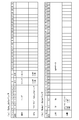
- the Sync_data of this embodiment sets the header (0th to 7th bits) to “10111111”, and determines whether it is Sync_data by detecting the header.
- the ninth bit defines reset. When the reset is “1: ON”, each speaker 2 performs a reset process.
- FIG. (B) in the figure shows an assignment example of the Normal_data pack.
- an enable (enable flag) is defined at the 0th bit. “Enable” indicates whether or not the corresponding data is valid, and each speaker 2 performs standby processing when the detection of the enable “0: invalid” continues for a predetermined time. Further, even if audio data is transmitted to all the speakers 2 on the daisy chain, if there is time remaining until the next sync timing, the remaining Normal_data pack enable flags are set to “0: invalid”.
- an example of a maximum of 32 bits is shown, but the number of bits per channel is not limited.
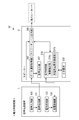
- FIG. 16 is a control block diagram of the audio transmission device 1.
- the audio transmission apparatus 1 includes a decoder 41a to 41c corresponding to each audio input source 4 such as a CD player, a Blu-ray player, a network player, a PLL 42a to 42c corresponding to each audio input source 4, and an SRC 43a corresponding to each audio input source 4.
- a clock generation unit 44 for generating a system clock
- a daisy format Gen45 for transmitting each sound data after frequency conversion by the SRCs 43a to 43c in synchronism with the sound output timing
- a memory 46 for storing each sound data
- various controls A nonvolatile memory 47 for storing programs and control data, and a CPU 48 (Central Processing Unit) for performing various arithmetic processes according to the control program stored in the nonvolatile memory 47 are provided.
- a CPU 48 Central Processing Unit
- Daisy format Gen 45 performs conversion to a data protocol as shown in FIG. Specifically, the audio data output from the SRCs 43a to 43c is rearranged in the order of transfer, or is replaced with a frequency clock for daisy chain transmission (a transmission clock synchronized with the clock on the reading side of the SRC 43). Or embed Sync_data. With this configuration, the audio transmission device 1 can send out audio data having different sampling rates on a single daisy chain.
- FIG. 17 is a control block diagram showing a modification of FIG. FIG. 17 shows an example of inputting a microphone signal.
- an analog signal is input in this way, it is digitized by the A / D converter 49.
- the clock used by the A / D converter 49 is the frequency clock on the reading side of the SRCs 43a and 43b, or is multiplied or This is a divided frequency clock.
- the SRC 43 corresponding to the analog signal input unit can be omitted.
- FIG. 18 is a control block diagram of the speaker 2.
- the speaker 2 includes a daisy data separation unit 51 that separates Sync_data and Normal_data from a frame, a PLL 52 that performs phase synchronization, a memory 53 that temporarily stores audio data, a counter 54 that measures sound output timing, DA converter 55, amplifier 56, audio output mechanism 57, non-volatile memory 58 for storing various control programs and various control data, control unit 59 for controlling the entire speaker 2, daisy active for daisy output active setting / inactive setting A control unit 60 is provided.
- the speaker 2 operates by generating an internal system clock by separating the Sync_data of the data input from Daisy In and assembling the PLL 52 in synchronization with the data. That is, a pulse is generated at the timing at which Sync_data is detected, and the pulse is input to the phase comparator of the PLL 52 as a primary source. Thereby, the operation clock of the DA converter 55 can be generated by the PLL 52. Since Sync_data is transmitted at a sampling frequency cycle, the PLL 52 generates a frequency clock obtained by multiplying the sampling frequency. In addition, the speaker 2 synchronizes the timing of sound output by temporarily storing the input data in the memory 53 (the sound output between the speakers 2 is adjusted with respect to the shift due to daisy chain transmission within one sampling frequency).
- FIG. 19 is a diagram illustrating the relationship between input data with different sampling rates and SRC output data.
- the figure for simplification, only one channel is input from each audio input source 4 (actually, a plurality of channels can be input for each audio input source 4).
- the upper part shows the signal input on the input side
- the lower part shows the output signal of the SRC 43. In this way, by passing through the SRC 43, the reproduction clock of each audio input source 4 is converted into a constant frequency clock.
- FIG. 20 is a diagram showing the relationship between the SRC output data and the transfer image on the daisy chain.
- S indicates Sync_data
- d * indicates the period (frame number).
- the SRC 43 is provided for each audio input source 4 and the reproduction clock of each audio input source 4 is converted into a constant frequency clock. Can be played simultaneously in one daisy chain. Also, since the audio data after frequency conversion is buffered in the memory 46, the output timing of the audio data can be synchronized (synchronized). Further, since a plurality of audio data is packed and transmitted in one frame, transmission control can be easily performed. In other words, compared to the case where packing is not performed, only one Sync_data (information for identifying data of the corresponding channel) is required, so the amount of data can be reduced, and one frame of data is aligned with 32 bits. Therefore, Sync_data detection and data separation of each channel can be easily performed. In addition, although the example of 32 bits was demonstrated, as long as it does not deviate from the meaning of this application, other numbers of bits are applicable.
- the speaker 2 is provided with a PLL 52 and generates an internal clock in synchronization with the separated Sync_data, so that synchronization with other speakers 2 can be achieved. Further, since the audio data is temporarily stored in the memory 53 and the output timing is counted by the counter 54, it is possible to eliminate the deviation of the sound output between the speakers due to the daisy chain transmission within one sampling frequency.
- the speaker 2 pauses the amplifier 56 and the like to enter a standby state, thereby reducing power consumption.
- the amplifier 56 is provided on the speaker 2 side, control can be performed independently for each channel, so that power consumption can be suppressed as compared with a configuration in which the amplifier is provided on the audio transmission device 1 side.
- FIGS. 27 a third embodiment of the present invention will be described with reference to FIGS.
- the present embodiment is characterized in that synchronized playback of a plurality of types of audio data having different sampling rates is realized using FiFo61 (First-In First-Out) (see FIG. 27). Only differences from the first and second embodiments will be described below.
- the same components as those in the first and second embodiments are denoted by the same reference numerals, and detailed description thereof is omitted. Also, modifications applied to the same configurations and parts as those in the first and second embodiments are similarly applied to this embodiment.
- FIG. 21 is a functional block diagram of the speaker system SY according to the third embodiment.
- the audio transmission device 1 includes an option ID assignment setting unit 121, an audio input unit 103, a device side buffer 122, a buffer monitoring unit 123, a transmission control unit 124, and a resync setting command unit 125 as main functional configurations.
- the option ID assignment setting unit 121 performs an option ID assignment process.
- the speaker ID of each speaker 2 is associated with the option ID. Details will be described later with reference to FIG.
- the voice input unit 103 inputs voice data from each voice input source 4.
- the apparatus-side buffer 122 buffers the audio data input from each audio input source 4, and corresponds to the FiFo 61 in FIG.
- the buffer monitoring unit 123 monitors the data amount of each device-side buffer 122 and corresponds to the FiFo data monitoring unit 62 in FIG.
- the transmission control unit 124 determines the number of pieces of audio data to be read from each device-side buffer 122 based on the monitoring result of each buffer monitoring unit 123, and packs each piece of audio data having the determined number of data into one frame. And transmit with a single clock.
- the transmission control unit 124 has the daisy format Gen 45 and the CPU 48 of FIG. 27 as main parts.
- the frame of this embodiment includes a channel data area group (“Ch1... Ch Last”) composed of a plurality of Normal_data (channel data areas) corresponding to each speaker 2 and each speaker.
- 2 includes an option data area group (“Op1... Op Last”) composed of a plurality of Option_data (option data areas) corresponding to 2.
- the transmission control unit 124 embeds a total of two samplings (two data) of audio data in the channel data area and the option data area.
- the transmission control unit 124 does not incorporate data into each data area.
- the transmission control unit 124 indicates, in an option flag, whether each channel data area corresponding to each speaker 2 has data in each option data area corresponding to each speaker 2. Similarly, the validity / invalidity of the corresponding data is represented by an enable flag in each channel data area corresponding to each speaker 2. With these flags, the speaker 2 is notified of the location of the transmitted data.
- the transmission control unit 124 represents a resync flag in the Sync_data pack of the frame.
- “when a predetermined condition is satisfied” refers to switching of audio input, changing the sampling rate of input audio data, turning on the power of the audio transmission device, starting output of audio data, and the like.
- the resync setting command unit 125 classifies the plurality of speakers 2 for each zone (for example, for each room) and commands the resync setting to each speaker 2 in the zone to be subjected to the synchronization process. On the speaker 2 side, synchronization processing is performed based on the command of the resync setting command unit 125 and the detection of the resync flag. Details will be described later with reference to FIGS.
- the speaker 2 has, as main control configurations, a data selection acquisition unit 202, a daisy chain output unit 203, a speaker side buffer 221, a buffer control unit 222, an audio output unit 207, a standby control unit 213, a resync setting unit 223, and a synchronization.
- a processing unit 224 is provided.
- the speaker-side buffer 221 buffers audio data transmitted from the audio transmission device 1, and corresponds to FiFo64 in FIG.
- the buffer control unit 222 writes audio data to the speaker side buffer 221 and monitors the amount of written data, and performs variable control of the read clock based on the monitoring result.
- the audio output unit 207 outputs audio based on audio data read from the speaker-side buffer 221 and corresponds to the audio output mechanism 57 in FIG.
- the standby control unit 213 sets the speaker 2 to the standby state when the detection of the enable flag “invalid” continues for a certain period of time.
- the resync setting unit 223 performs the resync setting of the speaker 2 according to the command of the resync setting command unit 125. Specifically, resync is set in the resync register.
- the synchronization processing unit 224 performs synchronization processing when the resync is set by the resync setting unit 223 and the resync flag “ON” is detected from the Sync_data pack.
- Sync_data of this embodiment defines a header at 0 to 7 bits and a reset at 9 bits. These are the same as in the second embodiment, but differ in that resync is defined at the eighth bit.
- the resynchronization is for causing the speaker 2 to execute resynchronization processing when it is necessary to regain synchronization as described above. Since there is no need for resynchronization processing when there is no change in the audio input, the normal Sync_data resync flag is set to “0: OFF”.
- (B) in the figure shows an assignment example of the Normal_data pack.
- the Normal_data of this embodiment is similar to the second embodiment in that enable is defined in the 0th bit, but differs in that an option (option flag) is defined in the 1st bit.
- the option is set to “1: Yes” if audio data is incorporated in the option data area, and “1: None” if audio data is not incorporated in the option data area.
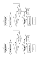
- the audio transmission device 1 determines whether or not there is a speaker 2 for which the speaker ID is set and the option ID is not set (S91). If it does not exist (S91: No), there is no need for the option ID assignment setting process, so an error process is performed (S92). If it exists (S91: Yes), the speaker ID to be set (initially “1”) is set (S93), and assignment loop processing is started sequentially (S94).
- the option ID to be set is set (the number of speakers plus the speaker ID, S95), and the set option ID is stored (S96).
- the speaker ID to be set is incremented (S98), and it is determined whether the speaker ID is valid (S99).
- S99 Yes when assignment of all the speakers 2 is not completed
- S94 and subsequent steps are repeated. If the speaker ID is invalid (if all the speakers 2 have been assigned, S99: No), the option ID assignment setting process is terminated.
- FIG. 25 is a flowchart showing a synchronization reset process on the voice transmission device 1 side. If the audio transmission device 1 determines that a synchronous reset process is necessary, such as when the sampling rate of input data is changed or when input switching is performed (S111: Yes), the audio transmission device 1 reads the speaker ID in the corresponding zone. (S112), the resync preprocessing loop of the speaker 2 in the corresponding zone is started (S113). In the resync preprocessing loop, the corresponding speaker 2 is set to mute (S114), and the resync setting is performed for each speaker 2 (S115).
- the mute command is issued to the corresponding speaker 2 and the setting to the resync register is commanded.
- the mute setting is for preventing noise due to the resync operation.
- the speaker ID of the first speaker 2 in the corresponding zone is read (S120), and a resync post-processing loop is started (S121).
- the resync post-processing loop the resync setting of the corresponding speaker 2 is canceled and the mute setting is canceled (S122, S123).
- S124 the post-resync processing loop is completed (S124)
- the next speaker ID in the corresponding zone is read (S125), and it is determined whether or not the remaining speaker 2 exists in the corresponding zone (S126). When it exists (S126: Yes), S120 and subsequent steps are repeated. If not (S126: No), the synchronization reset process is terminated.
- the speaker 2 refers to the resync register to determine whether or not the resync setting is performed (S131). If the resync setting is performed (S131: Yes), the mute setting is performed (S132). When Sync_data of the resync flag “1: ON” is input (S133: Yes), the resync operation is performed (S134). Thereafter, when a mute setting cancel command is acquired from the audio transmission device 1 (S135: Yes), the mute setting is canceled (S136), and the synchronization reset process is terminated. As described above, by performing the synchronization reset processing according to the flow of FIG. 25 and FIG. 26, even in the present embodiment in which each audio data is transmitted as one frame (even when only one Sync_data exists in the frame) ), You can resync for each zone.
- FIG. 27 is a control block diagram of the audio transmission device 1.
- the audio transmission device 1 includes decoders 41a and 41b corresponding to each audio input source 4 such as a CD player and a Blu-ray player, PLLs 42a and 42b corresponding to each audio input source 4, FiFo 61a and 61b corresponding to each audio input source 4, FiFo data monitoring units 62a and 62b that monitor the amount of data in each FiFo 61a and 61b, a clock generation unit 44 that generates a system clock, a daisy format Gen45 that transmits each audio data read from each FiFo 61a and 61b, and each audio data
- a memory 46 for storing, a resync timing Gen 63 for performing resync setting, a non-volatile memory 47 for storing various control programs and control data, and a CPU 48 for performing various arithmetic processes
- the audio transmission apparatus 1 detects that the amount of data in the FiFo 61 corresponding to the channel 1 exceeds the upper threshold by the FiFo data monitoring unit 62, the input of the channel 1 is faster than the daisy chain transmission ( The input rate exceeds the transfer rate), data for one sampling is stored in the channel data area of “Ch1”, and the next sampling data is stored in the option data area of “Ch1” (FIG. 22). reference).
- the input rate exceeds the transfer rate
- data for one sampling is stored in the channel data area of “Ch1”
- the next sampling data is stored in the option data area of “Ch1” (FIG. 22). reference).
- the daisy format Gen45 incorporates the enable “1: valid” in the 0th bit of the Normal_data pack and the option “1: present” in the 1st bit. .
- daisy format Gen 45 determines that the input of channel 1 is slower than daisy chain transmission, and the channel of “Ch1” Do not include in the data area. In this case, the daisy format Gen 45 enables the 0th bit of the Normal_data pack “0: invalid”.
- the resync timing Gen63 creates the timing for setting the sync_data resync flag. Specifically, when the CPU 48 detects that the sampling rate of input data has been changed or input switching has been performed, resync setting of the corresponding speaker 2 is performed. When the resync settings for all the speakers 2 have been completed, the resync timing Gen63 outputs a timing signal at the timing of Sync_data embedding, and the daisy format Gen45 sets the resync flag to “1: ON” in accordance with this signal. Is generated.
- FIG. 28 is a control block diagram of the speaker 2. As shown in the figure, the speaker 2 measures a sound output timing, a daisy data separation unit 51 that separates Sync_data and Normal_data from a frame, a PLL 52 for synchronizing with Sync_data, a memory 53 that temporarily stores audio data.
- a daisy data separation unit 51 that separates Sync_data and Normal_data from a frame
- a PLL 52 for synchronizing with Sync_data
- a memory 53 that temporarily stores audio data.
- FiFo64 for buffering audio data
- FiFo data monitoring unit 65 for monitoring the amount of data in FiFo64
- PLL 66 for changing the readout clock of FiFo64
- a transmission source for outputting channel assignment sound (identification signal) Identification signal Gen67
- selector 68 for switching between identification signal and normal sound
- DA converter 55 mute circuit 69 for muting the audio signal during synchronization reset processing
- amplifier 56 audio output mechanism 57
- Non-volatile memory 58 for storing data
- Manufacturers 2 controller 59 that controls the whole
- a daisy active control unit 60 for active set / inactive settings daisy output.
- the speaker 2 separates and captures “Ch1” data from the data (frame) input from Daisy In by the daisy data separation unit 51. If the enable flag of the fetched “Ch1” data is set to “1: Valid”, the data is written into the FiFo64. In addition, when the option flag is set to “1: present”, the data of “Op1” is also written. On the other hand, when the enable flag is set to “0: invalid”, writing to the FiFo 64 is not performed. Further, even when the option flag is set to “0: None”, the data of “Op1” is not written. Further, the data amount of FiFo64 is monitored by the FiFo data monitoring unit 65.
- the PLL 66 When the upper limit threshold is exceeded, the PLL 66 is controlled to increase the frequency clock on the reading side of the FiFo64. On the other hand, when the value falls below the lower limit threshold, the PLL 66 is controlled to lower the frequency clock on the reading side of the FiFo64. As a result, it is possible to perform audio reproduction in synchronization with the input of the audio transmission device 1 indirectly without emptying or overflowing the FiFo64.
- FIG. 29 is a diagram illustrating a relationship between input data with different sampling rates and data of FiFo output.
- the upper part shows the signal input on the input side
- the lower part shows the output signal on the reading side of the FiFo 64 provided in the speaker 2.
- the speaker 2 performs reproduction with a frequency clock equivalent to the frequency clock of the input audio input source 4.
- FIG. 30 is a diagram showing a relationship between input data with different sampling rates and a transfer image on the daisy chain.
- S indicates Sync_data
- the number represented by “d *” indicates the period (frame number).
- Dx indicates an enable flag “0: Invalid”, and “ox” indicates an option flag “0: None”.
- the first sampling data is the channel data area of the first frame
- the second sampling data is the channel data area of the second frame
- the third sampling data is the option of the second frame.
- the data data area, the fourth sampling data are incorporated into the channel data area of the third frame, and data transmission is performed.
- the audio transmission apparatus 1 side monitors the data amount of the FiFo 61 corresponding to each audio input source 4, and each audio data included in one frame based on the monitoring result.
- a plurality of types of audio data having different sampling rates can be transmitted.
- the transmitted audio data is once written in the FiFo 64, and the read clock is variably controlled according to the amount of data, so a plurality of types of audio data are reproduced simultaneously with one daisy chain speaker system.
- the voice transmission device 1 side when the data amount of FiFo 61 exceeds the upper threshold, when it is lower than the upper threshold and equal to or higher than the lower threshold, it is divided into three patterns when it falls below the lower threshold, and is transferred to the frame. Since the audio data is recorded and each pattern is indicated by an option flag and an enable flag, each pattern can be accurately discriminated on the speaker 2 side, and buffer writing processing and reproduction clock generation can be performed.
- the resync flag can be set in the Sync_data pack, when the audio input is switched, when the sampling rate of the input audio data is changed, when the audio transmission device 1 is turned on, when the output of the audio data is started, etc. Resynchronization processing can be performed at a necessary timing.
- the resync setting command unit 125 can command the resync setting to each speaker 2 in the zone to be synchronized, an efficient resynchronization process only for the speakers 2 in the zone requiring the resynchronization process. It can be performed.
- FIGS. 1 a fourth embodiment of the present invention will be described with reference to FIGS.
- the present embodiment is characterized in that power is supplied from the audio transmission device 1 to each speaker 2. Only the feature points different from the above embodiments will be described below.
- the same components as those in the above-described embodiments are denoted by the same reference numerals, and detailed description thereof is omitted.
- the modification applied about the structure similar to each said embodiment and a part is applied similarly about this embodiment.
- FIG. 31 is a functional block diagram of the speaker system SY according to the fourth embodiment.
- the arrows in the figure indicate the flow of audio data and the flow of power.
- functions related to power supply will be mainly described.
- the audio transmission device 1 includes an audio input unit 103, an audio transmission unit 131, a power supply unit 132, and a charging control unit 133 as main functional configurations.
- the voice input unit 103 inputs voice data from each voice input source 4.
- the audio transmission unit 131 packs each input audio data into a frame and transmits the daisy chain. Note that the audio transmission unit 131 functions as the transmission control units 106, 113, and 124 of the first to third embodiments.
- the power supply unit 132 charges the secondary batteries 232 in the plurality of speakers 2 connected in a daisy chain via the cable 3.
- the charging control unit 133 controls charging to each speaker 2 by switching target speakers to be specified as charging targets among the plurality of speakers 2 in a time-sharing manner (sequentially switching every predetermined time). Specifically, the elapsed time from the start of charging the target speaker is counted by a counter, an RTC (Real Time Clock) or the like, and when a predetermined time has elapsed, it is determined that charging is complete and the target speaker is switched.
- RTC Real Time Clock
- the speaker 2 includes a data separation unit 202, a daisy chain output unit 203, an audio output unit 207, a power control unit 231 and a secondary battery 232 as main functional configurations.
- the flow of audio data in the data separation unit 202, daisy chain output unit 203, and audio output unit 207 is the same as in each of the above embodiments.
- the power control unit 231 receives power supply from the audio transmission device 1 (charge control unit 133) via the cable 3 and charges the secondary battery 232. In addition, when the power control unit 231 is not designated as a target speaker to be charged, the power control unit 231 holds the charge stop state of the secondary battery 232.
- the secondary battery 232 various rechargeable batteries such as a lithium ion secondary battery and a lithium ion polymer secondary battery are applicable.
- the power control unit 231 includes a remaining amount detection unit 231a and a charge stop request transmission unit 231b.
- the remaining amount detection unit 231a detects the remaining amount of the secondary battery 232 of the speaker 2 itself.
- the charge stop request transmission unit 231b detects that the remaining amount of the secondary battery 232 exceeds a predetermined amount (first predetermined amount) by the remaining amount detection unit 231a, the charging stop request transmission unit 231b connects the cable 3 to the audio transmission device 1.
- a charge stop request is transmitted via
- the consumption ratio becomes a predetermined value or less (for example, 1/5 or less of the total battery capacity)
- the charging stop request may be transmitted at the same time.
- FIG. 32A is a diagram showing pin assignment of a straight connection type LAN cable. As shown in the figure, generally, only two pairs of Nos. 1, 2, 3, and 6 are used lines. For this reason, in this embodiment, as shown in FIG. 4B, the audio data is transmitted and the power is supplied using two unused pairs of lines 4, 5, 7, and 8.
- FIG. 33 is a flowchart showing the charging process on the voice transmission device 1 side.
- the audio transmission device 1 designates the target speaker to be charged by the speaker ID and notifies the target speaker (S141). Thereafter, the reception timeout of the ACK signal is determined (S142). If the timeout has occurred (S142: Yes), error processing is performed (S143). Specifically, the error is notified by voice output or screen display. On the other hand, when the time-out does not occur (S142: No) and an ACK signal is received from the target speaker (S144: Yes), charging is started (S145).
- the charging counter is set simultaneously with the start of charging (S146), and when the counting is ended (S147: Yes), charging is terminated and a charging timeout is notified to the target speaker (S148). Thereafter, the speaker ID is incremented (S149), and S141 and subsequent steps are repeated for the next-stage speaker 2.
- the charging is also terminated (S150), and the speaker ID is incremented (S149).
- FIG. 34 is a flowchart showing the charging process on the speaker 2 side.
- the speaker 2 target speaker determines the consistency between the received speaker ID and the ID stored in the speaker 2 (S162). If they match (if the speaker IDs match, S162: Yes), the ACK signal is returned to the audio transmission device 1 and the supply of power transmitted from the audio transmission device 1 is started (to the secondary battery 232). Charging is performed, S164). Thereafter, the remaining battery level of the secondary battery 232 is checked (S165), and when it is determined that the battery has become full (when it is detected that the remaining battery level of the secondary battery 232 exceeds a predetermined amount) (S166: Yes).
- the voice transmission device 1 is notified of a charge stop request (S167), and the charging process is terminated. On the other hand, also when the charging timeout notification is received from the audio transmission device 1 as the interrupt processing (S168), the charging processing is terminated.
- transmission and reception of various notifications and ACK signals use two pairs of lines 1, 2, 3, and 6 of the LAN cable (see FIG. 32).
- each speaker 2 can be achieved with only one cable 3. Can be stably supplied. As a result, power supply is not performed randomly, and the problem of allowable current capacity and the problem of voltage drop and heat generation due to the impedance of the power supply line can be solved.
- the target speaker to be charged is transmitted by transmitting the speaker ID used at the time of audio transmission, the target speaker can be easily and reliably switched.
- the system configuration can be further reduced.
- the charging stop state of the secondary battery 232 is maintained, so that more stable power supply can be performed as the entire system.
- the audio transmission device 1 since the audio transmission device 1 counts the elapsed time from the start of charging and switches the target speaker, the power transmission to each speaker 2 is performed in an appropriate cycle for maintaining a sufficiently charged state on average. It can be carried out.
- a charge stop request is received from the speaker 2 being charged, this is used as an interrupt process to switch the target speaker, so that overcharging can be prevented and power supply to each speaker 2 can be efficiently performed. Can do.
- charging is performed by designating target speakers one by one.
- target speakers may be designated by a plurality of units.
- the charging order may be from the downstream speaker 2 to the upstream side instead of going from the upstream speaker 2 to the downstream side, and the charging is performed in a random order regardless of the arrangement order of the speakers 2. May be.
- the target speaker may perform switching control for only the speaker 2 belonging to a specific zone (for example, the speaker 2 to be reproduced).
- a general-purpose LAN cable is used as a transmission path for supplying power, but a dedicated cable may be used.
- a dedicated speaker ID assigned for power supply may be used instead of the speaker ID used for audio transmission.
- each speaker 2 when it is detected that the remaining amount of the secondary battery 232 is equal to or less than a predetermined amount (second predetermined amount) during non-charging, You may transmit a charge start request
- the charging control unit 133 receives a charging start request from the non-charging speaker 2, the charging control unit 133 stops charging the charging speaker 2 or waits for the charging of the charging speaker 2 to be completed. It is preferable to switch the speaker 2 that has requested charging start to the target speaker.
- the speaker 2 is set as the next target speaker 2, and thus insufficient charging can be prevented. Thereby, the stable audio
- FIG. 35 is a system configuration diagram showing a first modification.
- cables 3a and 3b extend in two directions from the audio transmission device 1.
- two output terminals 12 for performing daisy chain output are required on the back surface of the audio transmission device 1 (see FIG. 3A).
- the audio data to be transmitted need not be distinguished for each of the cables 3a and 3b, and the same audio data may be transmitted.
- the degree of freedom of daisy chain connection can be improved by providing a plurality of output terminals 12 and only flowing the same data to both terminals.
- the number of output terminals 12 provided on the back surface of the audio transmission device 1 is arbitrary, and may be three or more.
- FIG. 36 is a system configuration diagram showing a second modification.
- This modification is characterized by using an omnidirectional speaker 2.
- a plurality of multi-channel spaces can be formed in one room.
- the television 81 and the audio transmission device 1 are connected.
- the source source of the projector 82 and the audio transmission device 1 are also connected.
- the omnidirectional speaker 2 for example, watching sports on the television 81 at some times and watching a movie on the projector 82 at some times can change the wiring. Instead, it can be realized only by changing the setting of the voice transmission device 1.
- the speaker 2a is used as a surround speaker (right side) placed behind the viewer, and in the latter case, it is used as a front speaker (left side) placed on the left and right of the screen.
- the speaker 2b is used as a surround speaker (left side) in the former and latter cases. Thereby, the same speaker 2 can be shared in a plurality of trial listening environments.
- the room can be easily redesigned.
- the usage of the speakers 2 can be changed simply by changing the settings of the audio transmission device 1 as described above.
- the speaker 2 used for the viewing environment on the TV 81 side is arranged, and when changing the pattern or adding a trial listening environment (for the projector 82, etc.), the corresponding speaker 2 is added and audio transmission is performed.
- two listening environments can be created.
- speaker system SY which combined these suitably may be realized.
- the program can be provided by being stored in various recording media (CD-ROM, flash memory, etc.). That is, a program for causing a computer to function as each part of the audio transmission device 1 or the speaker 2 and a recording medium on which the program is recorded are also included in the scope of the right of the present invention.
- the system configuration of the speaker system SY, the device configurations of the audio transmission device 1 and the speaker 2, processing steps, and the like can be appropriately changed without departing from the gist of the present invention, regardless of the above embodiment.
- Charge control unit 201 ... ID storage unit 202 ... Data selection acquisition unit 203 ... Daisy chain output unit 204 ... Data buffer 2 5 ... Interpolation data generation unit 206 ... Selection circuit 207 ... Audio output unit 208 ... Speaker side memory 211 ... Phase synchronization unit 212 ... Counter unit 213 ... Standby control unit 221 ... Speaker side buffer 222 ... Buffer control unit 223 ... Resync setting unit 224 ... Synchronization processing unit 231 ... Power control unit 231a ... Remaining amount detection unit 231b ... Charge stop request transmission unit 232 ... Secondary battery SY ... Speaker system
Abstract
La présente invention a pour but de fournir de l'énergie de manière stable à chaque haut-parleur qui est connecté en série dans seulement un trajet de transmission unique. Le dispositif de transmission audio (1) de la présente invention fournit de l'énergie par l'intermédiaire du trajet de transmission à une pluralité de haut-parleurs (2) qui sont connectés en série dans l'unique trajet de transmission, et est caractérisé en ce qu'il comporte : une unité d'alimentation électrique (132) pour charger des batteries secondaires (232) d'une pluralité de haut-parleurs (2) ; et une unité de commande de charge (133) qui commande la charge pour chacun des haut-parleurs (2) par commutation, sur une base de temps partagé, d'un haut-parleur à charger qui a été spécifié en tant qu'objet de charge parmi la pluralité de haut-parleurs (2).
Priority Applications (1)
| Application Number | Priority Date | Filing Date | Title |
|---|---|---|---|
| PCT/JP2011/004385 WO2013018141A1 (fr) | 2011-08-03 | 2011-08-03 | Dispositif d'alimentation électrique, dispositif de transmission audio, système de haut-parleurs, haut-parleur, procédé de commande de dispositif d'alimentation électrique et programme |
Applications Claiming Priority (1)
| Application Number | Priority Date | Filing Date | Title |
|---|---|---|---|
| PCT/JP2011/004385 WO2013018141A1 (fr) | 2011-08-03 | 2011-08-03 | Dispositif d'alimentation électrique, dispositif de transmission audio, système de haut-parleurs, haut-parleur, procédé de commande de dispositif d'alimentation électrique et programme |
Publications (1)
| Publication Number | Publication Date |
|---|---|
| WO2013018141A1 true WO2013018141A1 (fr) | 2013-02-07 |
Family
ID=47628718
Family Applications (1)
| Application Number | Title | Priority Date | Filing Date |
|---|---|---|---|
| PCT/JP2011/004385 WO2013018141A1 (fr) | 2011-08-03 | 2011-08-03 | Dispositif d'alimentation électrique, dispositif de transmission audio, système de haut-parleurs, haut-parleur, procédé de commande de dispositif d'alimentation électrique et programme |
Country Status (1)
| Country | Link |
|---|---|
| WO (1) | WO2013018141A1 (fr) |
Cited By (2)
| Publication number | Priority date | Publication date | Assignee | Title |
|---|---|---|---|---|
| WO2017094494A1 (fr) * | 2015-12-04 | 2017-06-08 | ヤマハ株式会社 | Système, terminal de commande, procédé de commande et programme |
| WO2022026291A1 (fr) * | 2020-07-31 | 2022-02-03 | Bose Corporation | Système de haut-parleurs line array alimenté avec réseau et alimentation électrique redondants |
Citations (1)
| Publication number | Priority date | Publication date | Assignee | Title |
|---|---|---|---|---|
| JP2009251891A (ja) * | 2008-04-04 | 2009-10-29 | Canon Inc | 情報処理装置、その制御方法及びプログラム |
-
2011
- 2011-08-03 WO PCT/JP2011/004385 patent/WO2013018141A1/fr active Application Filing
Patent Citations (1)
| Publication number | Priority date | Publication date | Assignee | Title |
|---|---|---|---|---|
| JP2009251891A (ja) * | 2008-04-04 | 2009-10-29 | Canon Inc | 情報処理装置、その制御方法及びプログラム |
Cited By (4)
| Publication number | Priority date | Publication date | Assignee | Title |
|---|---|---|---|---|
| WO2017094494A1 (fr) * | 2015-12-04 | 2017-06-08 | ヤマハ株式会社 | Système, terminal de commande, procédé de commande et programme |
| WO2022026291A1 (fr) * | 2020-07-31 | 2022-02-03 | Bose Corporation | Système de haut-parleurs line array alimenté avec réseau et alimentation électrique redondants |
| US11496833B2 (en) | 2020-07-31 | 2022-11-08 | Bose Corporation | Powered line array speaker system with redundant network and power supply |
| US11778380B2 (en) | 2020-07-31 | 2023-10-03 | Bose Corporation | Powered line array speaker system with redundant network and power supply |
Similar Documents
| Publication | Publication Date | Title |
|---|---|---|
| JP5934468B2 (ja) | 積層可能な通信システム | |
| CN104584567B (zh) | 音频转发设备和对应的方法 | |
| USRE45886E1 (en) | Information signal transmission system and remote control device for the same | |
| CN107634888B (zh) | 用于提供低延迟音频的系统、方法、装置和制品 | |
| EP2059066A1 (fr) | Système de reproduction sonore multimodal et procédé correspondant | |
| MX2012011016A (es) | Dispositivo colector, dispositivo de origen y sistema de transmision inalambrica. | |
| WO2005015901A1 (fr) | Recepteur de television et dispositifs externes | |
| CN102970633A (zh) | 设备控制装置、设备控制方法和程序 | |
| WO2009052223A1 (fr) | Amélioration du contrôle inter-éléments (cec) | |
| CN102088587A (zh) | 数字电视和用于控制数字电视中的外部装置的方法 | |
| CN102648606A (zh) | 终端装置、声音输出方法以及信息处理系统 | |
| CN109479176A (zh) | 同步音频回放设备 | |
| WO2013018141A1 (fr) | Dispositif d'alimentation électrique, dispositif de transmission audio, système de haut-parleurs, haut-parleur, procédé de commande de dispositif d'alimentation électrique et programme | |
| JP3975678B2 (ja) | 映像切換装置及び映像出力装置 | |
| EP2013767A2 (fr) | Procédé et système de sélection automatique de format audio numérique à partir d'un dispositif récepteur | |
| WO2013018139A1 (fr) | Système de haut-parleurs, dispositif de transmission audio, haut-parleur, procédé de transmission audio et programme | |
| WO2013018138A1 (fr) | Procédé de transmission audio, système de haut-parleurs, dispositif de transmission audio, haut-parleur et programme | |
| JP2005079614A (ja) | 移動型音声出力装置、コンテンツ再生装置、無線チャネル制御方法及び同期制御方法 | |
| WO2013018140A1 (fr) | Système de haut-parleurs, dispositif de transmission audio, haut-parleur, procédé de transmission audio et programme | |
| JP2008060675A (ja) | 音声再生装置、音声再生方法 | |
| JP7439758B2 (ja) | 送信装置、送信方法、受信装置および受信方法 | |
| US20110285878A1 (en) | Method for generating multimedia data to be displayed on display apparatus and associated multimedia player | |
| CN108282720B (zh) | 一种音频数据流的传输方法及装置 | |
| JP2005175570A (ja) | 映像音声出力装置 | |
| JPH09185577A (ja) | ディジタルインターフェース装置 |
Legal Events
| Date | Code | Title | Description |
|---|---|---|---|
| 121 | Ep: the epo has been informed by wipo that ep was designated in this application |
Ref document number: 11870207 Country of ref document: EP Kind code of ref document: A1 |
|
| NENP | Non-entry into the national phase |
Ref country code: DE |
|
| 122 | Ep: pct application non-entry in european phase |
Ref document number: 11870207 Country of ref document: EP Kind code of ref document: A1 |
|
| NENP | Non-entry into the national phase |
Ref country code: JP |