WO2013015063A1 - サイクロン分離装置およびこれを備える電気掃除機 - Google Patents
サイクロン分離装置およびこれを備える電気掃除機 Download PDFInfo
- Publication number
- WO2013015063A1 WO2013015063A1 PCT/JP2012/066364 JP2012066364W WO2013015063A1 WO 2013015063 A1 WO2013015063 A1 WO 2013015063A1 JP 2012066364 W JP2012066364 W JP 2012066364W WO 2013015063 A1 WO2013015063 A1 WO 2013015063A1
- Authority
- WO
- WIPO (PCT)
- Prior art keywords
- collection container
- peripheral surface
- compression member
- dust
- inner peripheral
- Prior art date
- Legal status (The legal status is an assumption and is not a legal conclusion. Google has not performed a legal analysis and makes no representation as to the accuracy of the status listed.)
- Ceased
Links
Images



Classifications
-
- A—HUMAN NECESSITIES
- A47—FURNITURE; DOMESTIC ARTICLES OR APPLIANCES; COFFEE MILLS; SPICE MILLS; SUCTION CLEANERS IN GENERAL
- A47L—DOMESTIC WASHING OR CLEANING; SUCTION CLEANERS IN GENERAL
- A47L9/00—Details or accessories of suction cleaners, e.g. mechanical means for controlling the suction or for effecting pulsating action; Storing devices specially adapted to suction cleaners or parts thereof; Carrying-vehicles specially adapted for suction cleaners
- A47L9/10—Filters; Dust separators; Dust removal; Automatic exchange of filters
- A47L9/106—Dust removal
- A47L9/108—Dust compression means
-
- A—HUMAN NECESSITIES
- A47—FURNITURE; DOMESTIC ARTICLES OR APPLIANCES; COFFEE MILLS; SPICE MILLS; SUCTION CLEANERS IN GENERAL
- A47L—DOMESTIC WASHING OR CLEANING; SUCTION CLEANERS IN GENERAL
- A47L9/00—Details or accessories of suction cleaners, e.g. mechanical means for controlling the suction or for effecting pulsating action; Storing devices specially adapted to suction cleaners or parts thereof; Carrying-vehicles specially adapted for suction cleaners
- A47L9/10—Filters; Dust separators; Dust removal; Automatic exchange of filters
- A47L9/16—Arrangement or disposition of cyclones or other devices with centrifugal action
- A47L9/1683—Dust collecting chambers; Dust collecting receptacles
Definitions
- the present invention relates to a cyclone separator and a vacuum cleaner provided with the same.
- Patent Document 3 of Japanese Patent Application Laid-Open No. 2010-119623 (Patent Document 1), Japanese Patent Application Laid-Open No. 2010-252998 (Patent Document 2), and Japanese Utility Model Application Nos. 53-152396 (55-68553). There is what is described in.
- the cyclone separator described in Patent Document 1 includes a collection container having a substantially cylindrical inner peripheral surface, and includes a rotatable compression member in the collection container.
- the compression member is rotated by a motor as a dust removal operation.
- the compression member rotates for several seconds as one dust removal operation.
- the dust accumulated in the collection container is guided downward by the spiral curved surface and compressed to the bottom of the collection container.
- a shade portion is provided in the middle of the cyclone separating cylinder taper portion, but it is not a structure for compressing accumulated dust.
- a bottom cover is provided at the lower end of the dust collection chamber. Open the bottom lid when throwing away the collected trash. By opening the bottom lid, the dust in the dust collection chamber naturally falls according to gravity. In this configuration, since the dust is not compressed, the dust is caught and remains above the planned position, and the dust can be accumulated at a high position as it is.
- JP 2010-119623 A JP 2010-252998 A Microfilm of Japanese Utility Model No. 53-152396 Japanese Utility Model Application Publication No. 55-68553
- the lower part of the compression member is a cylindrical member having a constant diameter called a rotating shaft portion.
- the lower end of the rotating shaft is in contact with the lower end of the collection container.
- Patent Document 1 In the configuration of Patent Document 1, as described in Patent Document 2, when it is attempted to adopt a method in which the bottom bottom lid is opened and the garbage falls naturally, the garbage is compressed in the collection container. Therefore, even if the bottom cover of the collection container is opened, there is a case where dust is difficult to fall between the inner peripheral surface of the collection container and the rotating shaft portion.
- an object of the present invention is to provide a cyclone separation device and a vacuum cleaner that compress dust in a collection container and that can be thrown away smoothly when the bottom cover is opened.
- a cyclone separating apparatus has a substantially cylindrical inner peripheral surface, and has an air inlet that is open at the bottom and passes through the outer wall so as to reach the inner peripheral surface.
- a collection container a bottom cover that can be opened and closed to close the bottom, a compression member that is disposed inside the collection container and is rotatable about a central axis of the inner peripheral surface of the collection container, and And a filter disposed at the center of the collection container on the upper side of the compression member.
- the cyclone separator is configured such that the air sucked from the air inlet is swirled along the inner peripheral surface of the collection container, and then exhausted through the filter, whereby the first size contained in the air is obtained.
- the compression member includes a disc portion that is spaced apart from the bottom lid, a rotary shaft portion that extends from the disc portion along the central axis toward the bottom lid, and an outer periphery of the compression member And a spiral protrusion provided to wrap around the surface.
- the rotating shaft portion includes a first portion that is spaced apart from the bottom lid, and a second portion that is closer to the bottom lid than the first portion and has a smaller diameter than the first portion.
- the spiral protrusion is disposed on the outer peripheral surface of the first portion.
- the present invention since it is possible to reduce the probability that dust is caught between the inner peripheral surface of the collection container and the rotating shaft portion, it is difficult to drop, so that the garbage is compressed in the collection container, and the bottom It is possible to provide a cyclone separator that can smoothly throw away garbage when the lid is opened.
- FIG. 1 It is a schematic diagram of the vacuum cleaner with which the cyclone separator in Embodiment 1 based on this invention is incorporated, and is also a schematic diagram of the vacuum cleaner in Embodiment 2. It is sectional drawing of the cyclone separation apparatus in Embodiment 1 based on this invention. It is an exploded view of the lower part of the cyclone separator in Embodiment 1 based on this invention. It is a side view in the state where the filter is attached of the inner cylinder contained in the cyclone separator in Embodiment 1 based on the present invention. It is a perspective view of the compression member contained in the cyclone separation apparatus in Embodiment 1 based on this invention.
- the cyclone separation apparatus 101 is used for the vacuum cleaner 201 shown in FIG. 1, for example.
- the electric vacuum cleaner 201 includes a vacuum cleaner body 1, an air inlet 2, a connection pipe 3, a connection hose 4, and an operation handle 5.
- the cyclone separator 101 is attached to the cleaner body 1.
- the cyclone separating apparatus 101 includes a grip portion 6. When the user holds and lifts the grip portion 6, the cyclone separating device 101 is taken out from the cleaner body 1.
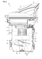
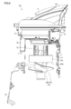
- a cross-sectional view of the extracted cyclone separator 101 is shown in FIG.
- the cyclone separating apparatus 101 includes an upper exterior part 10 that forms a part of the exterior of the cleaner body 1, an upper filter unit 13, a collection container 11, an inner cylinder 12, a compression member 23, and an airflow connection part 7.
- the dust removal drive unit 15 and the bottom cover 16 are provided.
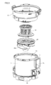
- FIG. 3 shows a disassembled main part of the lower part of the cyclone separator 101.
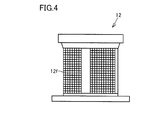
- FIG. 2 and FIG. 3 in order to show the structure of the inner cylinder 12, the state which removed the mesh-like filter attached to the outer peripheral surface of the inner cylinder 12 is displayed. Originally, as shown in FIG. 4, a mesh-like filter 12 f is attached to the outer peripheral surface of the inner cylinder 12.
- the cyclone separating apparatus 101 in the present embodiment has a substantially cylindrical inner peripheral surface 11r, a bottom 11b is opened, and an air inlet 7a that penetrates to reach the inner peripheral surface 11r in the middle of the outer wall.
- the cyclone separation device 101 swirls the air sucked from the air inlet 7a along the inner peripheral surface 11r of the collection container 11, and then exhausts it through the filter 12f, whereby the first size contained in the air is obtained.
- the collection object is collected at the bottom 11b of the collection container 11, and the collection object of the second size smaller than the first size is collected by the filter 12f, and further the third smaller than the second size.
- It is a cyclone separation device that collects a collection object of size with a filter (not shown) inside the upper filter unit 13.
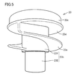
- the compression member 23 includes a disc portion 23d that is spaced apart from the bottom lid 16, a rotary shaft portion 23b that extends from the disc portion 23d along the central axis 11c toward the bottom lid 16, and a compression member 23.
- the rotation shaft portion 23 b includes a first portion 231 that is located away from the bottom lid 16, and a second portion 232 that is closer to the bottom lid 16 than the first portion 231 and has a smaller diameter than the first portion 231.
- the spiral protrusion 23 a is disposed on the outer peripheral surface of the first portion 231.
- FIG. 5 shows a state where the compression member 23 is taken out alone.
- the dust removal drive unit 15 includes a motor for rotating the compression member 23.
- the dust removal driving unit 15 is operated and the compression member 23 is continuously rotated for a predetermined time.
- the fixed time is, for example, about 8 seconds.
- the upper side of the disk portion 23d is a cylindrical portion 23c.
- the spiral protrusion 23a is provided only in a portion below the disc portion 23d and is not provided on the outer peripheral surface of the cylindrical portion 23c. However, the spiral protrusion 23a is not provided. May be provided continuously up to the outer peripheral surface of the cylindrical portion 23c.
- the collection container 11 is preferably transparent. This is because the amount of dust accumulated inside can be visually confirmed if it is transparent. It is preferable that the inside of the rotating shaft part 23b is hollow and the lower end is opened. This is because if the lower end of the rotating shaft portion 23b is open, the dust collected by the upper filter unit 13 and the like can be discharged when the bottom cover 16 is opened, as will be described later.
- the air that has passed through the filter 12 f installed in the inner cylinder 12 from the outside toward the inside is exhausted through the upper filter unit 13.
- first size When “first size”, “second size”, and “third size” are referred to with respect to the size of the dust, it does not only indicate that the diameter of the dust is a specific value, but is a numerical value in which the diameter of the dust is a fixed value. It means to be in range.
- FIG. 6 shows a cross-sectional view of the state in which the bottom cover 16 is opened in order to discharge dust.
- the bottom cover 16 is opened, not only the dust collected around the rotary shaft portion 23b in the bottom portion 11b of the collection container 11, but also the dust collected inside the rotary shaft portion 23b is discharged by natural fall.
- the rotation shaft portion 23b includes the second portion 232 having a diameter that is closer to the bottom cover 16, and the spiral protrusion 23a is not disposed on the outer surface of the second portion 232.
- the radial gap between the rotary shaft portion 23b and the inner peripheral surface 11r becomes large. As a result, it is possible to reduce the probability that the dust is difficult to fall between the inner peripheral surface of the collection container and the rotating shaft portion.
- the dust guided downward from the disk portion 23d is further guided toward the bottom portion 11b by the spiral protruding portion 23a outside the rotating shaft portion 23b.
- the cyclone separator 101 can be a cyclone separator that compresses dust in the collection container and smoothly throws away the dust when the bottom cover is opened.
- the second portion 232 may include a tapered portion whose diameter becomes narrower as the distance from the first portion 231 increases.
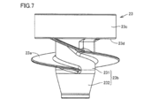
- the fact that the second portion 232 includes a tapered portion means that the entire second portion 232 may be tapered as shown in FIG. 7, and the second portion 232 may be formed as shown in FIGS. A part may be tapered. 7 to 9 are merely examples of variations in the shape of the second portion 232, and are not limited to these shapes.
- the second portion 232 includes a tapered portion whose diameter becomes smaller as the distance from the first portion 231 increases, dust collected between the inner peripheral surface 11r of the collection container 11 and the like. Is less likely to get caught, making it easier to fall naturally. Therefore, the dust can be thrown away more smoothly when the bottom cover is opened.
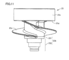
- the second portion 232 may have a stepped diameter that decreases as the distance from the first portion 231 increases. As described above, if the second portion 232 is configured to have a stepped diameter that decreases from the first portion 231, dust collected between the inner peripheral surface 11 r of the collection container 11 is less likely to be caught. It becomes easy to fall naturally. Therefore, the dust can be thrown away more smoothly when the bottom cover is opened.
- Embodiment 2 The vacuum cleaner in Embodiment 2 based on this invention is demonstrated.
- the vacuum cleaner in the present embodiment is the vacuum cleaner 201 shown in FIG.
- This vacuum cleaner includes any one of the cyclone separation devices described as the first embodiment and the modifications thereof.
- the present invention can be used for a cyclone separator and a vacuum cleaner provided with the same.
- Vacuum cleaner body 2 inlet port, 3 connection pipe, 4 connection hose, 5 operation handle, 6 gripping part, 7 airflow connection part, 7a air inlet, 10 upper exterior part, 11 collection container, 11b (collection (Bottom) bottom, 11c central axis, 11r inner peripheral surface, 12 inner cylinder, 12f filter, 13 upper filter unit, 15 dust removal drive unit, 16 bottom lid, 23 compression member, 23a spiral protrusion, 23b rotating shaft, 23c Cylindrical part, 23d disc part, 101 cyclone separator, 201 vacuum cleaner, 231 (rotary shaft part) first part, 232 (rotary shaft part) second part.
Landscapes
- Engineering & Computer Science (AREA)
- Mechanical Engineering (AREA)
- Filters For Electric Vacuum Cleaners (AREA)
- Cyclones (AREA)
Abstract
サイクロン分離装置(101)は、捕集容器(11)と、底蓋(16)と、回転可能な圧縮部材(23)と、圧縮部材(23)の上側に配置されたフィルタとを備える。空気流入口(7a)から吸い込まれた空気は、内周面(11r)に沿って旋回した後、上記フィルタを経て排気される。圧縮部材(23)は、底蓋(16)から離隔して配置される円板部(23d)と、円板部(23d)から底蓋(16)に向かって延在する回転軸部(23b)と、圧縮部材(23)の外周面に設けられた螺旋状突出部(23a)とを備える。回転軸部(23b)は、底蓋(16)から離隔して位置する第1部分(231)と、より小さな径の第2部分(232)とを有する。螺旋状突出部(23a)は、第1部分(231)の外周面に配置されている。
Description
本発明は、サイクロン分離装置およびこれを備える電気掃除機に関するものである。
従来から、電気掃除機に用いられるための数多くのサイクロン分離装置ないし集塵装置が提案されている。たとえば特開2010-119623号公報(特許文献1)、特開2010-252998号公報(特許文献2)、実願昭53-152396号(実開昭55-68553)のマイクロフィルム(特許文献3)に記載されたものがある。
特許文献1に記載されたサイクロン分離装置は、略円筒状の内周面を有する捕集容器を備え、捕集容器内に回転可能な圧縮部材を備えている。このサイクロン分離装置では、除塵動作としてモータにより圧縮部材が回転する。1回の除塵動作として数秒間にわたって圧縮部材が回転する。圧縮部材が回転すれば、捕集容器内に溜まったゴミは螺旋状曲面によって下方へと誘導され、捕集容器の底部に圧縮される。
特許文献2に記載された電気掃除機のサイクロン集塵室においては、サイクロン分離筒テーパ部の途中に笠部が設けられているが、溜まったゴミを圧縮する構造ではない。特許文献2に示された構成では、集塵室の下端に底蓋が設けられている。溜まったゴミを捨てる際に、底蓋を開放する。底蓋を開放することによって、集塵室内のゴミは、重力に従い自然落下する。この構成では、ゴミを圧縮しないので、予定位置より上にゴミがひっかかって残り、そのまま高い位置でゴミが溜まることもありうる。
特許文献3に記載された集塵装置では、円筒状の本体内に大きな空間があり、そのため、溜まっているゴミが少量の場合には、ゴミが本体内で暴れて舞い上がることとなる。
特許文献1に記載されたサイクロン分離装置においては、圧縮部材の下部は回転軸部と称する一定直径の円柱状の部材となっている。回転軸部の下端は捕集容器の下端に当接している。特許文献1の構成では、圧縮部材によってゴミを圧縮するので、ゴミが集積される位置が一定となり、捕集容器内でゴミが暴れることも避けられる。しかし、圧縮されたゴミには膨張しようとする力が働くので、捕集容器の内周面に対してゴミが押し付けられた状態となりうる。
特許文献1の構成において、特許文献2に記載されているように、下側の底蓋を開放してゴミを自然落下させる方式を採用しようとした場合、ゴミは捕集容器内で圧縮されているので、たとえ捕集容器の底蓋を開放しても、ゴミが捕集容器の内周面と回転軸部との間に挟まって落ちにくくなる場合があった。
そこで、本発明は、捕集容器内でゴミを圧縮し、なおかつ、底蓋開放の際にゴミが円滑に捨てられるサイクロン分離装置および電気掃除機を提供することを目的とする。
上記目的を達成するため、本発明に基づくサイクロン分離装置は、略円筒状の内周面を有し、底部が開口し、外壁の途中に上記内周面に至るように貫通した空気流入口を有する捕集容器と、上記底部を塞ぐ開閉自在な底蓋と、上記捕集容器の内部に配置され、上記捕集容器の上記内周面の中心軸を中心として回転可能な圧縮部材と、上記圧縮部材の上側において上記捕集容器の中心部に配置されたフィルタとを備える。このサイクロン分離装置は、上記空気流入口から吸い込まれた空気を上記捕集容器の上記内周面に沿って旋回させた後、上記フィルタを経て排気することにより、上記空気に含まれる第1サイズの捕集対象物を上記捕集容器の底部で捕集すると共に、上記第1サイズより小さい第2サイズの捕集対象物を上記フィルタにおいて捕集するサイクロン分離装置である。上記圧縮部材は、上記底蓋から離隔して配置される円板部と、上記円板部から上記中心軸に沿って上記底蓋に向かって延在する回転軸部と、上記圧縮部材の外周面に巻きつくように設けられた螺旋状突出部とを備える。上記回転軸部は、上記底蓋から離隔して位置する第1部分と、上記第1部分よりも上記底蓋寄りにあって上記第1部分より小さな径の第2部分とを有する。上記螺旋状突出部は、上記第1部分の外周面に配置されている。
本発明によれば、ゴミが捕集容器の内周面と回転軸部との間に挟まって落ちにくくなる確率を低減することができるので、捕集容器内でゴミを圧縮し、なおかつ、底蓋開放の際にゴミが円滑に捨てられるサイクロン分離装置を提供することができる。
(実施の形態1)
図1~図6を参照して、本発明に基づく実施の形態1におけるサイクロン分離装置101について説明する。サイクロン分離装置101は、たとえば図1に示す電気掃除機201に用いられるものである。電気掃除機201は、掃除機本体1と、吸気口部2と、接続管3と、接続ホース4と、操作ハンドル5とを備えている。サイクロン分離装置101は掃除機本体1に取り付けられている。サイクロン分離装置101は把持部6を備えている。ユーザが把持部6をつかんで持ち上げることによって、サイクロン分離装置101は掃除機本体1から取り出される。取り出されたサイクロン分離装置101の断面図を図2に示す。サイクロン分離装置101は、掃除機本体1の外装の一部をなす上外装部10と、上部フィルタユニット13と、捕集容器11と、内筒12と、圧縮部材23と、気流接続部7と、除塵駆動部15と、底蓋16とを備える。サイクロン分離装置101の下部の主要部を分解したところを図3に示す。図2、図3では、内筒12の構造を示すために、内筒12の外周面に取り付けられているメッシュ状のフィルタを取り外した状態を表示している。本来は、図4に示すように内筒12の外周面にはメッシュ状のフィルタ12fが取り付けられている。
図1~図6を参照して、本発明に基づく実施の形態1におけるサイクロン分離装置101について説明する。サイクロン分離装置101は、たとえば図1に示す電気掃除機201に用いられるものである。電気掃除機201は、掃除機本体1と、吸気口部2と、接続管3と、接続ホース4と、操作ハンドル5とを備えている。サイクロン分離装置101は掃除機本体1に取り付けられている。サイクロン分離装置101は把持部6を備えている。ユーザが把持部6をつかんで持ち上げることによって、サイクロン分離装置101は掃除機本体1から取り出される。取り出されたサイクロン分離装置101の断面図を図2に示す。サイクロン分離装置101は、掃除機本体1の外装の一部をなす上外装部10と、上部フィルタユニット13と、捕集容器11と、内筒12と、圧縮部材23と、気流接続部7と、除塵駆動部15と、底蓋16とを備える。サイクロン分離装置101の下部の主要部を分解したところを図3に示す。図2、図3では、内筒12の構造を示すために、内筒12の外周面に取り付けられているメッシュ状のフィルタを取り外した状態を表示している。本来は、図4に示すように内筒12の外周面にはメッシュ状のフィルタ12fが取り付けられている。
本実施の形態におけるサイクロン分離装置101は、略円筒状の内周面11rを有し、底部11bが開口し、外壁の途中に内周面11rに至るように貫通した空気流入口7aを有する捕集容器11と、底部11bを塞ぐ開閉自在な底蓋16と、捕集容器11の内部に配置され、捕集容器11の内周面11rの中心軸11cを中心として回転可能な圧縮部材23と、圧縮部材23の上側において前記捕集容器の中心部に配置されたフィルタ12fとを備える。サイクロン分離装置101は、空気流入口7aから吸い込まれた空気を捕集容器11の内周面11rに沿って旋回させた後、フィルタ12fを経て排気することにより、前記空気に含まれる第1サイズの捕集対象物を捕集容器11の底部11bで捕集すると共に、前記第1サイズより小さい第2サイズの捕集対象物をフィルタ12fにおいて捕集し、さらに前記第2サイズより小さい第3サイズの捕集対象物を、上部フィルタユニット13の内部にある図示しないフィルタで捕集するサイクロン分離装置である。圧縮部材23は、底蓋16から離隔して配置される円板部23dと、円板部23dから中心軸11cに沿って底蓋16に向かって延在する回転軸部23bと、圧縮部材23の外周面に巻きつくように設けられた螺旋状突出部23aとを備える。回転軸部23bは、底蓋16から離隔して位置する第1部分231と、第1部分231よりも底蓋16寄りにあって第1部分231より小さな径の第2部分232とを有する。螺旋状突出部23aは、第1部分231の外周面に配置されている。圧縮部材23を単独で取り出した状態を図5に示す。
除塵駆動部15は圧縮部材23を回転させるためのモータを含んでいる。サイクロン分離装置101は、ユーザが電気掃除機201の作動状態をオフにする操作をする度に、除塵駆動部15が作動して、圧縮部材23を一定時間回転させ続ける。一定時間とはたとえば約8秒間である。
圧縮部材23において円板部23dの上側は円筒部23cとなっている。本実施の形態では、螺旋状突出部23aは円板部23dより下の部分にのみ設けられており、円筒部23cの外周面には設けられていないものとして示したが、螺旋状突出部23aは、円筒部23cの外周面にまで連続して設けられていてもよい。
捕集容器11は透明であることが好ましい。透明であれば内部に溜まっているゴミの量を目視で確認することができるからである。回転軸部23bの内部は空洞となっており、下端は開口していることが好ましい。なぜなら、回転軸部23bの下端が開口していれば、上部フィルタユニット13などによって捕集したゴミを、後述するように、底蓋16開放時に排出することができるからである。
内筒12に設置されたフィルタ12fを外側から内側に向けて通過した空気は、上部フィルタユニット13を経由して排気される。
ゴミの大きさに関して「第1サイズ」、「第2サイズ」、「第3サイズ」という場合、ゴミの径が特定の数値であることのみを指すのではなく、ゴミの径がそれぞれ一定の数値範囲に入っていることを意味するものとする。
ゴミを排出するために底蓋16を開放した状態の断面図を図6に示す。底蓋16を開放したときには、捕集容器11の底部11bにおいて回転軸部23bの周りに溜まっていたゴミだけでなく、回転軸部23bの内部に溜まっていたゴミも自然落下により排出される。
本実施の形態では、回転軸部23bが底蓋16寄りに径が細くなった第2部分232を備えており、第2部分232の外面には螺旋状突出部23aが配置されていないので、捕集容器11の底蓋16付近では回転軸部23bと内周面11rとの間の半径方向の間隙が大きくなる。その結果、ゴミが捕集容器の内周面と回転軸部との間に挟まって落ちにくくなる確率を低減することができる。本実施の形態におけるサイクロン分離装置101では、円板部23dより下側に誘導されたゴミは、回転軸部23bの外側の螺旋状突出部23aによって底部11bに向けてさらに誘導される。このようにして、底部11bに誘導されて溜まった捕集容器内のゴミは、回転軸部23bの回転に伴う螺旋状突出部23aの回転によって圧縮される。したがって、本実施の形態におけるサイクロン分離装置101は、捕集容器内でゴミを圧縮し、なおかつ、底蓋開放の際にゴミが円滑に捨てられるサイクロン分離装置とすることができる。
なお、図7~図9に示すように、第2部分232は、第1部分231から遠ざかるにつれて径が細くなるテーパ状の部分を含んでいてもよい。第2部分232がテーパ状の部分を含むということは、図7に示すように第2部分232の全体がテーパ状であってもよく、図8、図9に示すように第2部分232の一部がテーパ状であってもよい。図7~図9に示したのはあくまでも第2部分232の形状のバリエーションの例示であって、これらの形状に限られない。このように、第2部分232が、第1部分231から遠ざかるにつれて径が細くなるテーパ状の部分を含む構成となっていれば、捕集容器11の内周面11rとの間に溜まったゴミがひっかかりにくくなり、自然落下しやすくなる。したがって、底蓋開放の際にゴミがより円滑に捨てられるようになる。
なお、図10、図11に示すように、第2部分232は、第1部分231から遠ざかるにつれて階段状に径が細くなっていてもよい。このように、第2部分232が、第1部分231から遠ざかるにつれて階段状に径が細くなる構成となっていれば、捕集容器11の内周面11rとの間に溜まったゴミがひっかかりにくくなり、自然落下しやすくなる。したがって、底蓋開放の際にゴミがより円滑に捨てられるようになる。
(実施の形態2)
本発明に基づく実施の形態2における電気掃除機について説明する。本実施の形態における電気掃除機は、図1に示した電気掃除機201である。この電気掃除機は、実施の形態1およびその変形例として説明したいずれかのサイクロン分離装置を備える。
本発明に基づく実施の形態2における電気掃除機について説明する。本実施の形態における電気掃除機は、図1に示した電気掃除機201である。この電気掃除機は、実施の形態1およびその変形例として説明したいずれかのサイクロン分離装置を備える。
本実施の形態によれば、捕集容器内でゴミを圧縮し、なおかつ、底蓋開放の際にゴミが円滑に捨てられる電気掃除機を実現することができる。
なお、今回開示した上記実施の形態はすべての点で例示であって制限的なものではない。本発明の範囲は上記した説明ではなくて請求の範囲によって示され、請求の範囲と均等の意味および範囲内でのすべての変更を含むものである。
本発明は、サイクロン分離装置およびこれを備える電気掃除機に利用することができる。
1 掃除機本体、2 吸気口部、3 接続管、4 接続ホース、5 操作ハンドル、6 把持部、7 気流接続部、7a 空気流入口、10 上外装部、11 捕集容器、11b (捕集容器の)底部、11c 中心軸、11r 内周面、12 内筒、12f フィルタ、13 上部フィルタユニット、15 除塵駆動部、16 底蓋、23 圧縮部材、23a 螺旋状突出部、23b 回転軸部、23c 円筒部、23d 円板部、101 サイクロン分離装置、201 電気掃除機、231 (回転軸部の)第1部分、232 (回転軸部の)第2部分。
Claims (4)
- 略円筒状の内周面(11r)を有し、底部(11b)が開口し、外壁の途中に前記内周面に至るように貫通した空気流入口(7a)を有する捕集容器(11)と、
前記底部を塞ぐ開閉自在な底蓋(16)と、
前記捕集容器の内部に配置され、前記捕集容器の前記内周面の中心軸を中心として回転可能な圧縮部材(23)と、
前記圧縮部材の上側において前記捕集容器の中心部に配置されたフィルタ(12f)とを備え、
前記空気流入口から吸い込まれた空気を前記捕集容器の前記内周面に沿って旋回させた後、前記フィルタを経て排気することにより、前記空気に含まれる第1サイズの捕集対象物を前記捕集容器の底部で捕集すると共に、前記第1サイズより小さい第2サイズの捕集対象物を前記フィルタにおいて捕集するサイクロン分離装置(101)であって、
前記圧縮部材は、前記底蓋から離隔して配置される円板部(23d)と、
前記円板部から前記中心軸に沿って前記底蓋に向かって延在する回転軸部(23b)と、
前記圧縮部材の外周面に巻きつくように設けられた螺旋状突出部(23a)とを備え、
前記回転軸部は、前記底蓋から離隔して位置する第1部分(231)と、前記第1部分よりも前記底蓋寄りにあって前記第1部分より小さな径の第2部分(232)とを有し、前記螺旋状突出部は、前記第1部分の外周面に配置されている、サイクロン分離装置。 - 前記第2部分は、前記第1部分から遠ざかるにつれて径が細くなるテーパ状の部分を含む、請求項1に記載のサイクロン分離装置。
- 前記第2部分は、前記第1部分から遠ざかるにつれて階段状に径が細くなっている、請求項1に記載のサイクロン分離装置。
- 請求項1に記載のサイクロン分離装置を備える、電気掃除機。
Applications Claiming Priority (2)
| Application Number | Priority Date | Filing Date | Title |
|---|---|---|---|
| JP2011165594A JP5107452B1 (ja) | 2011-07-28 | 2011-07-28 | サイクロン分離装置およびこれを備える電気掃除機 |
| JP2011-165594 | 2011-07-28 |
Publications (1)
| Publication Number | Publication Date |
|---|---|
| WO2013015063A1 true WO2013015063A1 (ja) | 2013-01-31 |
Family
ID=47528555
Family Applications (1)
| Application Number | Title | Priority Date | Filing Date |
|---|---|---|---|
| PCT/JP2012/066364 Ceased WO2013015063A1 (ja) | 2011-07-28 | 2012-06-27 | サイクロン分離装置およびこれを備える電気掃除機 |
Country Status (3)
| Country | Link |
|---|---|
| JP (1) | JP5107452B1 (ja) |
| CN (1) | CN202821203U (ja) |
| WO (1) | WO2013015063A1 (ja) |
Families Citing this family (8)
| Publication number | Priority date | Publication date | Assignee | Title |
|---|---|---|---|---|
| KR102308501B1 (ko) * | 2015-03-27 | 2021-10-06 | 삼성전자주식회사 | 사이클론 집진장치 및 이를 포함하는 진공 청소기 |
| US10299646B2 (en) | 2016-05-03 | 2019-05-28 | Lg Electronics Inc. | Vacuum cleaner |
| KR101852435B1 (ko) | 2016-05-03 | 2018-04-26 | 엘지전자 주식회사 | 진공 청소기 |
| US10299645B2 (en) | 2016-05-03 | 2019-05-28 | Lg Electronics Inc. | Vacuum cleaner |
| KR101822944B1 (ko) | 2016-05-03 | 2018-01-29 | 엘지전자 주식회사 | 진공 청소기 |
| US10271702B2 (en) | 2016-05-03 | 2019-04-30 | Lg Electronics Inc. | Vacuum cleaner |
| US10299647B2 (en) * | 2016-05-03 | 2019-05-28 | Lg Electronics Inc. | Vacuum cleaner |
| KR102350782B1 (ko) * | 2017-07-04 | 2022-01-14 | 엘지전자 주식회사 | 청소기 |
Citations (6)
| Publication number | Priority date | Publication date | Assignee | Title |
|---|---|---|---|---|
| JP4070787B2 (ja) * | 2005-12-14 | 2008-04-02 | シャープ株式会社 | 電気掃除機 |
| JP2010063751A (ja) * | 2008-09-12 | 2010-03-25 | Panasonic Corp | 電気掃除機 |
| JP2010081962A (ja) * | 2008-09-29 | 2010-04-15 | Sharp Corp | サイクロン分離装置 |
| JP2010099236A (ja) * | 2008-10-23 | 2010-05-06 | Sharp Corp | 電気掃除機 |
| JP2011078463A (ja) * | 2009-10-05 | 2011-04-21 | Sharp Corp | 電気掃除機 |
| JP2011092476A (ja) * | 2009-10-30 | 2011-05-12 | Sharp Corp | 電気掃除機 |
-
2011
- 2011-07-28 JP JP2011165594A patent/JP5107452B1/ja not_active Expired - Fee Related
-
2012
- 2012-06-27 WO PCT/JP2012/066364 patent/WO2013015063A1/ja not_active Ceased
- 2012-07-27 CN CN 201220367101 patent/CN202821203U/zh not_active Expired - Lifetime
Patent Citations (6)
| Publication number | Priority date | Publication date | Assignee | Title |
|---|---|---|---|---|
| JP4070787B2 (ja) * | 2005-12-14 | 2008-04-02 | シャープ株式会社 | 電気掃除機 |
| JP2010063751A (ja) * | 2008-09-12 | 2010-03-25 | Panasonic Corp | 電気掃除機 |
| JP2010081962A (ja) * | 2008-09-29 | 2010-04-15 | Sharp Corp | サイクロン分離装置 |
| JP2010099236A (ja) * | 2008-10-23 | 2010-05-06 | Sharp Corp | 電気掃除機 |
| JP2011078463A (ja) * | 2009-10-05 | 2011-04-21 | Sharp Corp | 電気掃除機 |
| JP2011092476A (ja) * | 2009-10-30 | 2011-05-12 | Sharp Corp | 電気掃除機 |
Also Published As
| Publication number | Publication date |
|---|---|
| CN202821203U (zh) | 2013-03-27 |
| JP2013027552A (ja) | 2013-02-07 |
| JP5107452B1 (ja) | 2012-12-26 |
Similar Documents
| Publication | Publication Date | Title |
|---|---|---|
| JP5101720B1 (ja) | サイクロン分離装置およびこれを備える電気掃除機 | |
| JP5107452B1 (ja) | サイクロン分離装置およびこれを備える電気掃除機 | |
| JP4750164B2 (ja) | サイクロン分離装置 | |
| JP2010081968A (ja) | サイクロン分離装置 | |
| JP2010035771A (ja) | サイクロン分離装置 | |
| KR101641257B1 (ko) | 진공청소기용 집진장치 | |
| WO2009116611A1 (ja) | サイクロン分離装置 | |
| JP6867991B2 (ja) | 電気掃除機 | |
| JP2010104502A (ja) | 電気掃除機 | |
| JP2010004909A (ja) | サイクロン分離装置 | |
| JP4378420B2 (ja) | サイクロン分離装置 | |
| CN102578960B (zh) | 电动吸尘器 | |
| JP4856271B2 (ja) | サイクロン分離装置 | |
| JP4871416B2 (ja) | サイクロン分離装置 | |
| JP6334204B2 (ja) | 集塵装置、及び電気掃除機 | |
| JP5841563B2 (ja) | 電気掃除機 | |
| JP7365484B2 (ja) | 電気掃除機 | |
| JP5184428B2 (ja) | サイクロン分離装置 | |
| JP5122406B2 (ja) | サイクロン分離装置 | |
| JP5212874B2 (ja) | 電気掃除機 | |
| JP2011005344A (ja) | 電気掃除機 | |
| JP2018008154A (ja) | 電気掃除機 | |
| JP2015006623A (ja) | サイクロン分離装置、電気掃除機 | |
| JP5066282B2 (ja) | サイクロン分離装置 | |
| JP2012061345A (ja) | 電気掃除機 |
Legal Events
| Date | Code | Title | Description |
|---|---|---|---|
| 121 | Ep: the epo has been informed by wipo that ep was designated in this application |
Ref document number: 12818119 Country of ref document: EP Kind code of ref document: A1 |
|
| NENP | Non-entry into the national phase |
Ref country code: DE |
|
| 122 | Ep: pct application non-entry in european phase |
Ref document number: 12818119 Country of ref document: EP Kind code of ref document: A1 |