WO2013012042A1 - Système, dispositif et procédé de traitement d'image, et dispositif de diagnostic par imagerie médicale - Google Patents
Système, dispositif et procédé de traitement d'image, et dispositif de diagnostic par imagerie médicale Download PDFInfo
- Publication number
- WO2013012042A1 WO2013012042A1 PCT/JP2012/068371 JP2012068371W WO2013012042A1 WO 2013012042 A1 WO2013012042 A1 WO 2013012042A1 JP 2012068371 W JP2012068371 W JP 2012068371W WO 2013012042 A1 WO2013012042 A1 WO 2013012042A1
- Authority
- WO
- WIPO (PCT)
- Prior art keywords
- image
- volume data
- unit
- stereoscopic
- parallax
- Prior art date
Links
Images


Classifications
-
- G—PHYSICS
- G06—COMPUTING; CALCULATING OR COUNTING
- G06T—IMAGE DATA PROCESSING OR GENERATION, IN GENERAL
- G06T15/00—3D [Three Dimensional] image rendering
- G06T15/08—Volume rendering
-
- A—HUMAN NECESSITIES
- A61—MEDICAL OR VETERINARY SCIENCE; HYGIENE
- A61B—DIAGNOSIS; SURGERY; IDENTIFICATION
- A61B6/00—Apparatus for radiation diagnosis, e.g. combined with radiation therapy equipment
- A61B6/46—Apparatus for radiation diagnosis, e.g. combined with radiation therapy equipment with special arrangements for interfacing with the operator or the patient
- A61B6/461—Displaying means of special interest
- A61B6/466—Displaying means of special interest adapted to display 3D data
-
- G—PHYSICS
- G06—COMPUTING; CALCULATING OR COUNTING
- G06T—IMAGE DATA PROCESSING OR GENERATION, IN GENERAL
- G06T19/00—Manipulating 3D models or images for computer graphics
- G06T19/20—Editing of 3D images, e.g. changing shapes or colours, aligning objects or positioning parts
-
- A—HUMAN NECESSITIES
- A61—MEDICAL OR VETERINARY SCIENCE; HYGIENE
- A61B—DIAGNOSIS; SURGERY; IDENTIFICATION
- A61B90/00—Instruments, implements or accessories specially adapted for surgery or diagnosis and not covered by any of the groups A61B1/00 - A61B50/00, e.g. for luxation treatment or for protecting wound edges
- A61B90/36—Image-producing devices or illumination devices not otherwise provided for
- A61B90/37—Surgical systems with images on a monitor during operation
- A61B2090/372—Details of monitor hardware
-
- A—HUMAN NECESSITIES
- A61—MEDICAL OR VETERINARY SCIENCE; HYGIENE
- A61B—DIAGNOSIS; SURGERY; IDENTIFICATION
- A61B90/00—Instruments, implements or accessories specially adapted for surgery or diagnosis and not covered by any of the groups A61B1/00 - A61B50/00, e.g. for luxation treatment or for protecting wound edges
- A61B90/50—Supports for surgical instruments, e.g. articulated arms
- A61B2090/502—Headgear, e.g. helmet, spectacles
-
- G—PHYSICS
- G01—MEASURING; TESTING
- G01R—MEASURING ELECTRIC VARIABLES; MEASURING MAGNETIC VARIABLES
- G01R33/00—Arrangements or instruments for measuring magnetic variables
- G01R33/20—Arrangements or instruments for measuring magnetic variables involving magnetic resonance
- G01R33/44—Arrangements or instruments for measuring magnetic variables involving magnetic resonance using nuclear magnetic resonance [NMR]
- G01R33/48—NMR imaging systems
- G01R33/54—Signal processing systems, e.g. using pulse sequences ; Generation or control of pulse sequences; Operator console
- G01R33/56—Image enhancement or correction, e.g. subtraction or averaging techniques, e.g. improvement of signal-to-noise ratio and resolution
- G01R33/5608—Data processing and visualization specially adapted for MR, e.g. for feature analysis and pattern recognition on the basis of measured MR data, segmentation of measured MR data, edge contour detection on the basis of measured MR data, for enhancing measured MR data in terms of signal-to-noise ratio by means of noise filtering or apodization, for enhancing measured MR data in terms of resolution by means for deblurring, windowing, zero filling, or generation of gray-scaled images, colour-coded images or images displaying vectors instead of pixels
-
- G—PHYSICS
- G06—COMPUTING; CALCULATING OR COUNTING
- G06T—IMAGE DATA PROCESSING OR GENERATION, IN GENERAL
- G06T2210/00—Indexing scheme for image generation or computer graphics
- G06T2210/41—Medical
-
- G—PHYSICS
- G06—COMPUTING; CALCULATING OR COUNTING
- G06T—IMAGE DATA PROCESSING OR GENERATION, IN GENERAL
- G06T2219/00—Indexing scheme for manipulating 3D models or images for computer graphics
- G06T2219/20—Indexing scheme for editing of 3D models
- G06T2219/2021—Shape modification
-
- H—ELECTRICITY
- H04—ELECTRIC COMMUNICATION TECHNIQUE
- H04N—PICTORIAL COMMUNICATION, e.g. TELEVISION
- H04N13/00—Stereoscopic video systems; Multi-view video systems; Details thereof
- H04N13/30—Image reproducers
- H04N13/302—Image reproducers for viewing without the aid of special glasses, i.e. using autostereoscopic displays
- H04N13/305—Image reproducers for viewing without the aid of special glasses, i.e. using autostereoscopic displays using lenticular lenses, e.g. arrangements of cylindrical lenses
-
- H—ELECTRICITY
- H04—ELECTRIC COMMUNICATION TECHNIQUE
- H04N—PICTORIAL COMMUNICATION, e.g. TELEVISION
- H04N13/00—Stereoscopic video systems; Multi-view video systems; Details thereof
- H04N13/30—Image reproducers
- H04N13/349—Multi-view displays for displaying three or more geometrical viewpoints without viewer tracking
- H04N13/351—Multi-view displays for displaying three or more geometrical viewpoints without viewer tracking for displaying simultaneously
Definitions
- Embodiments described herein relate generally to an image processing system, apparatus, method, and medical image diagnostic apparatus.
- a technique for displaying a stereoscopically visible image for a user using dedicated equipment such as stereoscopic glasses by displaying two images captured from two viewpoints on a monitor is known.
- an image captured from a plurality of viewpoints (for example, nine images) is displayed on a monitor using a light controller such as a lenticular lens, so that an image that can be stereoscopically viewed by a naked-eye user can be obtained.
- a technique for displaying is known. Note that a plurality of images displayed on a stereoscopically visible monitor may be generated by estimating depth information of an image taken from one viewpoint and performing image processing using the estimated information.
- X-ray CT Computer Tomography
- MRI Magnetic Resonance Imaging
- ultrasonic diagnostic apparatuses apparatuses capable of generating three-dimensional medical image data (hereinafter referred to as volume data) are practical. It has become.
- a medical image diagnostic apparatus generates a planar image for display by executing various image processing on the volume data, and displays it on a general-purpose monitor.
- the medical image diagnostic apparatus generates a two-dimensional rendering image in which three-dimensional information about the subject is reflected by performing volume rendering processing on the volume data, and the generated rendering image is displayed on the general-purpose monitor. Display above.
- the problem to be solved by the present invention is to provide an image processing system, apparatus, method, and medical image diagnostic apparatus capable of displaying a stereoscopic image in a subject during surgery before surgery.
- the image processing system includes a reception unit, an estimation unit, a rendering processing unit, and a display control unit.
- the accepting unit accepts an operation of applying a virtual force to the subject indicated by the stereoscopic image.
- the estimation unit estimates the position variation of the voxel group included in the volume data based on the force received by the reception unit.
- the rendering processing unit generates a new parallax image group by changing the arrangement of the voxel groups included in the volume data based on the estimation result by the estimation unit and performing the rendering process on the changed volume data.
- the display control unit causes the stereoscopic display device to display the parallax image group newly generated by the rendering processing unit.
- FIG. 1 is a diagram for explaining a configuration example of an image processing system according to the first embodiment.
- FIG. 2A is a diagram (1) illustrating an example of a stereoscopic display monitor that performs stereoscopic display using two parallax images.
- FIG. 2B is a diagram (2) illustrating an example of a stereoscopic display monitor that performs stereoscopic display using two parallax images.
- FIG. 3 is a diagram for explaining an example of a stereoscopic display monitor that performs stereoscopic display with nine parallax images.
- FIG. 4 is a diagram for explaining a configuration example of the workstation according to the first embodiment.
- FIG. 5 is a diagram for explaining a configuration example of the rendering processing unit shown in FIG. FIG.
- FIG. 6 is a diagram for explaining an example of volume rendering processing according to the first embodiment.
- FIG. 7 is a diagram for explaining an example of processing performed by the image processing system according to the first embodiment.
- FIG. 8 is a diagram for explaining the terminal device according to the first embodiment.
- FIG. 9 is a diagram illustrating an example of a correspondence relationship between the stereoscopic image space and the volume data space.
- FIG. 10 is a diagram for explaining a configuration example of a control unit in the first embodiment.
- FIG. 11 is a diagram for explaining an example of an estimation process by the estimation unit according to the first embodiment.
- FIG. 12 is a sequence diagram illustrating an example of a processing flow by the image processing system according to the first embodiment.
- FIG. 13 is a diagram for explaining an example of processing by the image processing system according to the second embodiment.
- FIG. 14 is a diagram for explaining an example of the estimation process by the estimation unit according to the second embodiment.
- FIG. 15 is a sequence diagram illustrating an example of a flow of processing by the image processing system according to the second embodiment.
- FIG. 16 is a diagram for explaining a modification of the second embodiment.
- FIG. 17 is a diagram for explaining a modification of the second embodiment.
- FIG. 18 is a diagram for explaining a modification of the second embodiment.
- FIG. 19 is a diagram for explaining a modification of the second embodiment.
- FIG. 20 is a diagram for explaining a modification of the second embodiment.
- the “parallax image group” is an image generated by performing volume rendering processing by moving the viewpoint position by a predetermined parallax angle with respect to volume data. It is a group. That is, the “parallax image group” includes a plurality of “parallax images” having different “viewpoint positions”.
- the “parallax angle” is a predetermined position in the space represented by the volume data and an adjacent viewpoint position among the viewpoint positions set to generate the “parallax image group” (for example, the center of the space) It is an angle determined by.
- the “parallax number” is the number of “parallax images” necessary for stereoscopic viewing on the stereoscopic display monitor.
- the “9 parallax images” described below is a “parallax image group” composed of nine “parallax images”.
- the “two-parallax image” described below is a “parallax image group” composed of two “parallax images”.
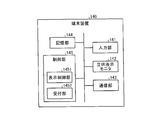
- FIG. 1 is a diagram for explaining a configuration example of an image processing system according to the first embodiment.
- the image processing system 1 includes a medical image diagnostic apparatus 110, an image storage apparatus 120, a workstation 130, and a terminal apparatus 140.
- Each device illustrated in FIG. 1 is in a state where it can communicate with each other directly or indirectly by, for example, an in-hospital LAN (Local Area Network) 2 installed in a hospital.
- an in-hospital LAN Local Area Network
- PACS Picture Archiving and Communication System
- each apparatus transmits and receives medical images and the like according to the DICOM (Digital Imaging and Communications in Medicine) standard.
- DICOM Digital Imaging and Communications in Medicine
- the image processing system 1 generates a parallax image group from volume data that is three-dimensional medical image data generated by the medical image diagnostic apparatus 110, and displays the parallax image group on a stereoscopically viewable monitor.
- a stereoscopic image which is an image that can be visually recognized by the observer, is provided to an observer such as a doctor or a laboratory technician working in the hospital.
- the workstation 130 performs various image processes on the volume data to generate a parallax image group.
- the workstation 130 and the terminal device 140 have a stereoscopically visible monitor, and display a stereoscopic image to the user by displaying a parallax image group generated by the workstation 130 on the monitor.
- the image storage device 120 stores the volume data generated by the medical image diagnostic device 110 and the parallax image group generated by the workstation 130.
- the workstation 130 or the terminal device 140 acquires volume data or a parallax image group from the image storage device 120, executes arbitrary image processing on the acquired volume data or parallax image group, or selects a parallax image group. Or display on a monitor.
- each device will be described in order.
- the medical image diagnostic apparatus 110 includes an X-ray diagnostic apparatus, an X-ray CT (Computed Tomography) apparatus, an MRI (Magnetic Resonance Imaging) apparatus, an ultrasonic diagnostic apparatus, a SPECT (Single Photon Emission Computed Tomography) apparatus, and a PET (Positron Emission computed Tomography). ) Apparatus, a SPECT-CT apparatus in which a SPECT apparatus and an X-ray CT apparatus are integrated, a PET-CT apparatus in which a PET apparatus and an X-ray CT apparatus are integrated, or a group of these apparatuses. Further, the medical image diagnostic apparatus 110 according to the first embodiment can generate three-dimensional medical image data (volume data).
- the medical image diagnostic apparatus 110 generates volume data by imaging a subject.
- the medical image diagnostic apparatus 110 collects data such as projection data and MR signals by imaging the subject, and medical image data of a plurality of axial surfaces along the body axis direction of the subject from the collected data.
- volume data is generated.
- the medical image diagnostic apparatus 110 reconstructs 500 pieces of medical image data on the axial plane
- the 500 pieces of medical image data groups on the axial plane become volume data.
- the projection data of the subject imaged by the medical image diagnostic apparatus 110, the MR signal, or the like may be used as the volume data.
- the medical image diagnostic apparatus 110 transmits the generated volume data to the image storage apparatus 120.
- the medical image diagnostic apparatus 110 identifies, for example, a patient ID for identifying a patient, an examination ID for identifying an examination, and the medical image diagnostic apparatus 110 as supplementary information when transmitting volume data to the image storage apparatus 120.
- a device ID, a series ID for identifying one shot by the medical image diagnostic device 110, and the like are transmitted.
- the image storage device 120 is a database that stores medical images. Specifically, the image storage device 120 according to the first embodiment receives volume data from the medical image diagnostic device 110 and stores the received volume data in a predetermined storage unit. In the first embodiment, the workstation 130 generates a parallax image group from the volume data, and transmits the generated parallax image group to the image storage device 120. For this reason, the image storage device 120 stores the parallax image group transmitted from the workstation 130 in a predetermined storage unit. In the present embodiment, the workstation 130 illustrated in FIG. 1 and the image storage device 120 may be integrated by using the workstation 130 that can store a large-capacity image. That is, this embodiment may be a case where volume data or a parallax image group is stored in the workstation 130 itself.
- the volume data and the parallax image group stored in the image storage device 120 are stored in association with the patient ID, examination ID, device ID, series ID, and the like. For this reason, the workstation 130 and the terminal device 140 acquire necessary volume data and a parallax image group from the image storage device 120 by performing a search using a patient ID, an examination ID, a device ID, a series ID, and the like.
- the workstation 130 is an image processing apparatus that performs image processing on medical images. Specifically, the workstation 130 according to the first embodiment generates a parallax image group by performing various rendering processes on the volume data acquired from the image storage device 120.
- the workstation 130 has a monitor (also referred to as a stereoscopic display monitor or a stereoscopic image display device) capable of displaying a stereoscopic image as a display unit.
- the workstation 130 generates a parallax image group and displays the generated parallax image group on the stereoscopic display monitor.
- the operator of the workstation 130 can perform an operation for generating a parallax image group while confirming the stereoscopically viewable stereoscopic image displayed on the stereoscopic display monitor.
- the workstation 130 transmits the generated parallax image group to the image storage device 120 and the terminal device 140.
- the workstation 130 transmits, for example, a patient ID, an examination ID, a device ID, a series ID, and the like as supplementary information.
- the incidental information transmitted when transmitting the parallax image group to the image storage device 120 includes incidental information regarding the parallax image group.
- the incidental information regarding the parallax image group includes the number of parallax images (for example, “9”), the resolution of the parallax images (for example, “466 ⁇ 350 pixels”), and the volume data that is the generation source of the parallax image group. There is information on the three-dimensional virtual space represented by (volume space information).
- the terminal device 140 is a device for allowing a doctor or laboratory technician working in a hospital to view a medical image.
- the terminal device 140 is a PC (Personal Computer), a tablet PC, a PDA (Personal Digital Assistant), a mobile phone, or the like operated by a doctor or laboratory technician working in a hospital.
- the terminal device 140 according to the first embodiment includes a stereoscopic display monitor as a display unit.
- the terminal device 140 acquires a parallax image group from the image storage device 120 and displays the acquired parallax image group on the stereoscopic display monitor.
- a doctor or laboratory technician who is an observer can view a medical image that can be viewed stereoscopically.
- the terminal device 140 may be any information processing terminal connected to a stereoscopic display monitor as an external device.
- a general-purpose monitor that is most popular at present displays a two-dimensional image in two dimensions, and cannot display a two-dimensional image in three dimensions. If an observer requests stereoscopic viewing on a general-purpose monitor, an apparatus that outputs an image to the general-purpose monitor needs to display two parallax images that can be viewed stereoscopically by the observer in parallel by the parallel method or the intersection method. is there.
- an apparatus that outputs an image to a general-purpose monitor for example, uses an after-color method with an eyeglass that has a red cellophane attached to the left eye portion and a blue cellophane attached to the right eye portion. It is necessary to display a stereoscopically viewable image.
- a stereoscopic display monitor there is a stereoscopic display monitor capable of stereoscopically viewing a two-parallax image (also referred to as a binocular parallax image) by using dedicated equipment such as stereoscopic glasses.
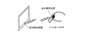
- FIGS. 2A and 2B are diagrams for explaining an example of a stereoscopic display monitor that performs stereoscopic display using two parallax images.
- An example shown in FIGS. 2A and 2B is a stereoscopic display monitor that performs stereoscopic display by a shutter method, and shutter glasses are used as stereoscopic glasses worn by an observer who observes the monitor.
- Such a stereoscopic display monitor emits two parallax images alternately on the monitor.
- the monitor shown in FIG. 2A alternately emits a left-eye image and a right-eye image at 120 Hz.
- the monitor is provided with an infrared emitting unit, and the infrared emitting unit controls the emission of infrared rays in accordance with the timing at which the image is switched.
- the infrared light emitted from the infrared light emitting unit is received by the infrared light receiving unit of the shutter glasses shown in FIG. 2A.
- a shutter is attached to each of the left and right frames of the shutter glasses, and the shutter glasses alternately switch the transmission state and the light shielding state of the left and right shutters according to the timing when the infrared light receiving unit receives the infrared rays.
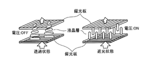
- the switching process between the transmission state and the light shielding state in the shutter will be described.
- each shutter has an incident-side polarizing plate and an output-side polarizing plate, and further has a liquid crystal layer between the incident-side polarizing plate and the output-side polarizing plate.
- the incident-side polarizing plate and the outgoing-side polarizing plate are orthogonal to each other.
- the light passing through the incident-side polarizing plate is rotated 90 degrees by the action of the liquid crystal layer, and the outgoing-side polarizing plate is To Penetrate. That is, a shutter to which no voltage is applied is in a transmissive state.
- the infrared emitting unit emits infrared rays while the image for the left eye is displayed on the monitor.
- the infrared light receiving unit applies a voltage to the right-eye shutter without applying a voltage to the left-eye shutter during a period of receiving the infrared light.
- the right-eye shutter is in a light-shielding state and the left-eye shutter is in a transmissive state, so that an image for the left eye enters the left eye of the observer.
- the infrared ray emitting unit stops emitting infrared rays while the right-eye image is displayed on the monitor.
- the infrared light receiving unit applies a voltage to the left-eye shutter without applying a voltage to the right-eye shutter during a period in which no infrared light is received. Accordingly, the left-eye shutter is in a light-shielding state and the right-eye shutter is in a transmissive state, so that an image for the right eye is incident on the right eye of the observer.
- the stereoscopic display monitor illustrated in FIGS. 2A and 2B displays an image that can be viewed stereoscopically by the observer by switching the image displayed on the monitor and the state of the shutter in conjunction with each other.
- a monitor adopting a polarized glasses method is also known in addition to the shutter method described above.
- a stereoscopic display monitor that allows a viewer to stereoscopically view a multi-parallax image such as a 9-parallax image with the naked eye by using a light controller such as a lenticular lens.
- a light controller such as a lenticular lens.
- Such a stereoscopic display monitor enables stereoscopic viewing based on binocular parallax, and also enables stereoscopic viewing based on motion parallax that also changes the image observed in accordance with the viewpoint movement of the observer.
- FIG. 3 is a diagram for explaining an example of a stereoscopic display monitor that performs stereoscopic display with nine parallax images.
- a light beam controller is arranged on the front surface of a flat display surface 200 such as a liquid crystal panel.
- a vertical lenticular sheet 201 whose optical aperture extends in the vertical direction is attached to the front surface of the display surface 200 as a light beam controller.
- the vertical lenticular sheet 201 is pasted so that the convex portion of the vertical lenticular sheet 201 becomes the front surface, but the convex portion of the vertical lenticular sheet 201 is pasted so as to face the display surface 200. There may be.
- the display surface 200 has an aspect ratio of 3: 1 and pixels in which three sub-pixels, red (R), green (G), and blue (B), are arranged in the vertical direction. 202 are arranged in a matrix.
- the stereoscopic display monitor shown in FIG. 3 converts a nine-parallax image composed of nine images into an intermediate image arranged in a predetermined format (for example, a lattice shape), and then outputs it to the display surface 200. That is, the stereoscopic display monitor shown in FIG. 3 assigns and outputs nine pixels at the same position in nine parallax images to nine columns of pixels 202.
- the nine columns of pixels 202 constitute a unit pixel group 203 that simultaneously displays nine images with different viewpoint positions.
- the nine-parallax images simultaneously output as the unit pixel group 203 on the display surface 200 are emitted as parallel light by, for example, an LED (Light Emitting Diode) backlight, and further emitted in multiple directions by the vertical lenticular sheet 201.
- an LED Light Emitting Diode
- the light incident on the right eye and the left eye of the observer changes in conjunction with the position of the observer (viewpoint position). That is, the parallax angle between the parallax image incident on the right eye and the parallax image incident on the left eye differs depending on the viewing angle of the observer.
- the observer can visually recognize the photographing object in three dimensions at each of the nine positions shown in FIG. 3, for example.
- the observer can view the image three-dimensionally in a state of facing the object to be imaged at the position “5” shown in FIG. 3, and at each position other than “5” shown in FIG. It can be visually recognized in a three-dimensional manner with the direction of the object changed.
- the stereoscopic display monitor shown in FIG. 3 is merely an example.
- the stereoscopic display monitor that displays the nine-parallax image may be a horizontal stripe liquid crystal of “RRR..., GGG..., BBB. .. ”” May be used.
- the stereoscopic display monitor shown in FIG. 3 may be a vertical lens system in which the lenticular sheet is vertical as shown in FIG. 3 or a diagonal lens system in which the lenticular sheet is oblique. There may be.
- the configuration example of the image processing system 1 according to the first embodiment has been briefly described.
- the application of the image processing system 1 described above is not limited when PACS is introduced.
- the image processing system 1 is similarly applied when an electronic medical chart system that manages an electronic medical chart to which a medical image is attached is introduced.
- the image storage device 120 is a database that stores electronic medical records.
- the image processing system 1 is similarly applied when a HIS (Hospital Information System) and a RIS (Radiology Information System) are introduced.
- HIS Hospital Information System
- RIS Radiology Information System
- the image processing system 1 is not limited to the configuration example described above. The functions and sharing of each device may be appropriately changed according to the operation mode.
- FIG. 4 is a diagram for explaining a configuration example of the workstation according to the first embodiment.
- the “parallax image group” refers to a group of stereoscopic images generated by performing volume rendering processing on volume data. Further, the “parallax image” is an individual image constituting the “parallax image group”. That is, the “parallax image group” includes a plurality of “parallax images” having different viewpoint positions.
- the workstation 130 is a high-performance computer suitable for image processing and the like, and as illustrated in FIG. 4, an input unit 131, a display unit 132, a communication unit 133, and a storage unit 134. And a control unit 135 and a rendering processing unit 136.
- the workstation 130 is a high-performance computer suitable for image processing or the like.
- the present invention is not limited to this, and may be any information processing apparatus. For example, any personal computer may be used.
- the input unit 131 is a mouse, a keyboard, a trackball, or the like, and receives input of various operations on the workstation 130 from the operator. Specifically, the input unit 131 according to the first embodiment receives input of information for acquiring volume data to be subjected to rendering processing from the image storage device 120. For example, the input unit 131 receives input of a patient ID, an examination ID, a device ID, a series ID, and the like. Further, the input unit 131 according to the first embodiment receives an input of a condition regarding rendering processing (hereinafter, rendering condition).
- rendering condition a condition regarding rendering processing
- the display unit 132 is a liquid crystal panel or the like as a stereoscopic display monitor, and displays various types of information. Specifically, the display unit 132 according to the first embodiment displays a GUI (Graphical User Interface) for receiving various operations from the operator, a parallax image group, and the like.
- the communication unit 133 is a NIC (Network Interface Card) or the like, and communicates with other devices.
- the storage unit 134 is a hard disk, a semiconductor memory element, or the like, and stores various information. Specifically, the storage unit 134 according to the first embodiment stores volume data acquired from the image storage device 120 via the communication unit 133. In addition, the storage unit 134 according to the first embodiment stores volume data during rendering processing, a group of parallax images generated by the rendering processing, and the like.
- the control unit 135 is an electronic circuit such as a CPU (Central Processing Unit), MPU (Micro Processing Unit) or GPU (Graphics Processing Unit), or an integrated circuit such as an ASIC (Application Specific Integrated Circuit) or FPGA (Field Programmable Gate Array). Yes, the entire control of the workstation 130 is performed.
- CPU Central Processing Unit
- MPU Micro Processing Unit
- GPU Graphics Processing Unit
- ASIC Application Specific Integrated Circuit
- FPGA Field Programmable Gate Array
- control unit 135 controls the display of the GUI and the display of the parallax image group on the display unit 132.
- the control unit 135 controls transmission / reception of volume data and a parallax image group performed with the image storage device 120 via the communication unit 133.
- the control unit 135 controls the rendering process performed by the rendering processing unit 136.
- the control unit 135 controls reading of volume data from the storage unit 134 and storage of the parallax image group in the storage unit 134.
- the rendering processing unit 136 performs various rendering processes on the volume data acquired from the image storage device 120 under the control of the control unit 135, and generates a parallax image group. Specifically, the rendering processing unit 136 according to the first embodiment reads volume data from the storage unit 134 and first performs preprocessing on the volume data. Next, the rendering processing unit 136 performs a volume rendering process on the pre-processed volume data to generate a parallax image group. Subsequently, the rendering processing unit 136 generates a two-dimensional image in which various kinds of information (scale, patient name, examination item, etc.) are drawn, and superimposes it on each of the parallax image groups, thereby outputting 2 for output. Generate a dimensional image.
- rendering processing refers to the entire image processing performed on volume data.
- Volume rendering processing refers to a two-dimensional image reflecting three-dimensional information in the rendering processing. It is a process to generate.
- a parallax image corresponds to the medical image generated by the rendering process.
- FIG. 5 is a diagram for explaining a configuration example of the rendering processing unit shown in FIG.
- the rendering processing unit 136 includes a preprocessing unit 1361, a 3D image processing unit 1362, and a 2D image processing unit 1363.
- the preprocessing unit 1361 performs preprocessing on the volume data
- the 3D image processing unit 1362 generates a parallax image group from the preprocessed volume data
- the 2D image processing unit 1363 stores various information on the parallax image group.
- a two-dimensional image for output on which is superimposed is generated.
- each part is demonstrated in order.
- the preprocessing unit 1361 is a processing unit that performs various types of preprocessing when rendering processing is performed on volume data, and includes an image correction processing unit 1361a, a three-dimensional object fusion unit 1361e, and a three-dimensional object display area setting. Part 1361f.
- the image correction processing unit 1361a is a processing unit that performs image correction processing when processing two types of volume data as one volume data, and as illustrated in FIG. 5, a distortion correction processing unit 1361b, a body motion correction processing unit, 1361c and an inter-image registration processing unit 1361d.
- the image correction processing unit 1361a performs image correction processing when processing volume data of a PET image generated by a PET-CT apparatus and volume data of an X-ray CT image as one volume data.
- the image correction processing unit 1361a performs image correction processing when processing the volume data of the T1-weighted image and the volume data of the T2-weighted image generated by the MRI apparatus as one volume data.
- the distortion correction processing unit 1361b corrects the data distortion caused by the collection conditions at the time of data collection by the medical image diagnostic apparatus 110 in each volume data.
- the body motion correction processing unit 1361c corrects the movement caused by the body motion of the subject at the time of collecting the data used for generating the individual volume data.
- the inter-image registration processing unit 1361d performs registration (Registration) using, for example, a cross-correlation method between the two volume data subjected to the correction processing by the distortion correction processing unit 1361b and the body motion correction processing unit 1361c. )I do.
- the three-dimensional object fusion unit 1361e fuses a plurality of volume data that have been aligned by the inter-image alignment processing unit 1361d. Note that the processing of the image correction processing unit 1361a and the three-dimensional object fusion unit 1361e is omitted when rendering processing is performed on single volume data.
- the three-dimensional object display area setting unit 1361f is a processing unit that sets a display area corresponding to a display target organ designated by the operator, and includes a segmentation processing unit 1361g.
- the segmentation processing unit 1361g is a processing unit that extracts organs such as the heart, lungs, and blood vessels designated by the operator by, for example, a region expansion method based on pixel values (voxel values) of volume data.
- segmentation processing unit 1361 g does not perform the segmentation processing when the display target organ is not designated by the operator.
- the segmentation processing unit 1361g extracts a plurality of corresponding organs when a plurality of display target organs are designated by the operator. Further, the processing of the segmentation processing unit 1361g may be executed again in response to an operator fine adjustment request referring to the rendered image.
- the 3D image processing unit 1362 performs a volume rendering process on the pre-processed volume data processed by the pre-processing unit 1361.
- a 3D image processing unit 1362 includes a projection method setting unit 1362a, a 3D geometric transformation processing unit 1362b, a 3D object appearance processing unit 1362f, and a 3D virtual space rendering unit 1362k.
- Projection method setting unit 1362a determines a projection method for generating a parallax image group. For example, the projection method setting unit 1362a determines whether to execute the volume rendering process by the parallel projection method or the perspective projection method.
- the three-dimensional geometric transformation processing unit 1362b is a processing unit that determines information for transforming volume data on which volume rendering processing is performed into a three-dimensional geometrical structure.
- the three-dimensional geometric transformation processing unit 1362b includes a parallel movement processing unit 1362c, a rotation processing unit 1362d, and an enlargement unit.
- a reduction processing unit 1362e is included.
- the translation processing unit 1362c is a processing unit that determines the amount of movement to translate the volume data when the viewpoint position when performing the volume rendering processing is translated, and the rotation processing unit 1362d performs the volume rendering processing. This is a processing unit that determines the amount of movement to rotate the volume data when the viewpoint position at the time of rotation is rotated.
- the enlargement / reduction processing unit 1362e is a processing unit that determines the enlargement rate or reduction rate of the volume data when enlargement or reduction of the parallax image group is requested.
- the 3D object appearance processing unit 1362f includes a 3D object color processing unit 1362g, a 3D object opacity processing unit 1362h, a 3D object material processing unit 1362i, and a 3D virtual space light source processing unit 1362j.
- the three-dimensional object appearance processing unit 1362f performs a process of determining the display state of the displayed parallax image group in response to an operator's request, for example.
- the three-dimensional object color processing unit 1362g is a processing unit that determines a color to be colored for each region segmented by the volume data.
- the three-dimensional object opacity processing unit 1362h is a processing unit that determines the opacity (Opacity) of each voxel constituting each region segmented by volume data. It should be noted that the area behind the area having the opacity of “100%” in the volume data is not drawn in the parallax image group. In addition, an area in which the opacity is “0%” in the volume data is not drawn in the parallax image group.
- the three-dimensional object material processing unit 1362i is a processing unit that determines the material of each region segmented by volume data and adjusts the texture when this region is rendered.
- the three-dimensional virtual space light source processing unit 1362j is a processing unit that determines the position of the virtual light source installed in the three-dimensional virtual space and the type of the virtual light source when performing volume rendering processing on the volume data. Examples of the virtual light source include a light source that emits parallel rays from infinity, a light source that emits radial rays from a viewpoint, and the like.
- the 3D virtual space rendering unit 1362k performs volume rendering processing on the volume data to generate a parallax image group.
- the three-dimensional virtual space rendering unit 1362k performs various types of information determined by the projection method setting unit 1362a, the three-dimensional geometric transformation processing unit 1362b, and the three-dimensional object appearance processing unit 1362f as necessary when performing the volume rendering process. Is used.
- the volume rendering process by the three-dimensional virtual space rendering unit 1362k is performed according to the rendering conditions.
- the rendering condition is “parallel projection method” or “perspective projection method”.
- the rendering condition is “reference viewpoint position, parallax angle, and number of parallaxes”.
- the rendering conditions are “translation of viewpoint position”, “rotational movement of viewpoint position”, “enlargement of parallax image group”, and “reduction of parallax image group”.
- the rendering conditions are “color to be colored”, “transparency”, “texture”, “position of virtual light source”, and “type of virtual light source”.
- Such a rendering condition may be accepted from the operator via the input unit 131 or may be initially set.
- the three-dimensional virtual space rendering unit 1362k receives a rendering condition from the control unit 135, and performs volume rendering processing on the volume data according to the rendering condition.
- the projection method setting unit 1362a, the three-dimensional geometric transformation processing unit 1362b, and the three-dimensional object appearance processing unit 1362f determine various pieces of necessary information according to the rendering conditions, so the three-dimensional virtual space rendering unit 1362k. Generates a parallax image group using the determined various pieces of information.
- FIG. 6 is a diagram for explaining an example of the volume rendering process according to the first embodiment.
- the three-dimensional virtual space rendering unit 1362k accepts the parallel projection method as a rendering condition, and further, the reference viewpoint position (5) and the parallax. Assume that the angle “1 degree” is received. In such a case, the three-dimensional virtual space rendering unit 1362k translates the position of the viewpoint from (1) to (9) so that the parallax angle is every “1 degree”, and performs the parallax angle (line of sight) by the parallel projection method.
- the three-dimensional virtual space rendering unit 1362k sets a light source that emits parallel rays from infinity along the line-of-sight direction.
- the three-dimensional virtual space rendering unit 1362k accepts a perspective projection method as a rendering condition, and further, the reference viewpoint position (5) and the parallax Assume that the angle “1 degree” is received. In such a case, the three-dimensional virtual space rendering unit 1362k rotates and moves the viewpoint position from (1) to (9) so that the parallax angle is “1 degree” around the center (center of gravity) of the volume data. Thus, nine parallax images having different parallax angles by 1 degree are generated by the perspective projection method.
- the three-dimensional virtual space rendering unit 1362k sets a point light source or a surface light source that radiates light three-dimensionally radially around the viewing direction at each viewpoint.
- the viewpoints (1) to (9) may be moved in parallel depending on rendering conditions.
- the three-dimensional virtual space rendering unit 1362k radiates light two-dimensionally radially around the line-of-sight direction with respect to the vertical direction of the displayed volume rendered image, and the horizontal direction of the displayed volume rendered image.
- volume rendering processing using both the parallel projection method and the perspective projection method may be performed by setting a light source that emits parallel light rays from infinity along the line-of-sight direction.
- the nine parallax images generated in this way are a group of parallax images.
- the nine parallax images are converted into intermediate images arranged in a predetermined format (for example, a lattice shape) by the control unit 135, for example, and are output to the display unit 132 as a stereoscopic display monitor.
- the operator of the workstation 130 can perform an operation for generating a parallax image group while confirming a stereoscopically viewable medical image displayed on the stereoscopic display monitor.
- the rendering unit 1362k generates a parallax image group while reflecting each rendering condition.
- the 3D virtual space rendering unit 1362k has a function of reconstructing an MPR image from volume data by performing a cross-section reconstruction method (MPR: Multi Planer Reconstruction) in addition to volume rendering.
- MPR Multi Planer Reconstruction
- the three-dimensional virtual space rendering unit 1362k also has a function of performing “Curved MPR” and a function of performing “Intensity Projection”.
- the parallax image group generated from the volume data by the three-dimensional image processing unit 1362 is an underlay.
- an overlay (Overlay) on which various types of information (scale, patient name, examination item, etc.) are drawn is superimposed on the underlay, thereby obtaining a two-dimensional image for output.
- the two-dimensional image processing unit 1363 is a processing unit that generates an output two-dimensional image by performing image processing on the overlay and the underlay. As illustrated in FIG. 5, the two-dimensional object drawing unit 1363a, A two-dimensional geometric transformation processing unit 1363b and a luminance adjustment unit 1363c are included.
- the two-dimensional image processing unit 1363 superimposes one overlay on each of nine parallax images (underlays) in order to reduce the load required to generate a two-dimensional image for output.
- nine output two-dimensional images are generated.
- an underlay with an overlay superimposed may be simply referred to as a “parallax image”.
- the two-dimensional object drawing unit 1363a is a processing unit that draws various information drawn on the overlay, and the two-dimensional geometric transformation processing unit 1363b performs parallel movement processing or rotational movement processing on the position of the various information drawn on the overlay. Or a processing unit that performs an enlargement process or a reduction process of various types of information drawn on the overlay.
- the luminance adjustment unit 1363c is a processing unit that performs luminance conversion processing. For example, an image such as gradation of an output destination stereoscopic display monitor, window width (WW: Window Width), window level (WL: Window Level), or the like. This is a processing unit that adjusts the brightness of the overlay and the underlay according to the processing parameters.
- WW Window Width
- WL Window Level
- the control unit 135 temporarily stores the output two-dimensional image generated in this manner in the storage unit 134 and then transmits the two-dimensional image to the image storage device 120 via the communication unit 133. Then, for example, the terminal device 140 acquires the two-dimensional image for output from the image storage device 120, converts it into an intermediate image arranged in a predetermined format (for example, a lattice shape), and displays it on the stereoscopic display monitor. For example, the control unit 135 temporarily stores the output two-dimensional image in the storage unit 134, and then transmits the output two-dimensional image to the image storage device 120 and the terminal device 140 via the communication unit 133.
- a predetermined format for example, a lattice shape
- the terminal device 140 converts the output two-dimensional image received from the workstation 130 into an intermediate image arranged in a predetermined format (for example, a lattice shape) and displays the converted image on the stereoscopic display monitor. Accordingly, a doctor or a laboratory technician who uses the terminal device 140 can browse a stereoscopically viewable medical image in a state where various information (scale, patient name, examination item, etc.) is drawn.
- a predetermined format for example, a lattice shape
- the stereoscopic display monitor described above provides a stereoscopic image that can be viewed stereoscopically by an observer by displaying a parallax image group.
- an observer such as a doctor observes a three-dimensional image of various organs such as blood vessels, brains, hearts, and lungs by observing a stereoscopic image before performing an open operation (craniotomy, thoracotomy, laparotomy, etc.). It is possible to grasp the correct positional relationship.
- the various organs in the subject are surrounded by bones (skulls, ribs, etc.) and muscles, and can be said to be sealed in the human body.
- the brain when the brain is opened, the brain may expand slightly outside the body and rise from the craniotomy portion.
- organs such as the lung, heart, intestine, and liver may expand slightly outside the body when opened or opened.
- the stereoscopic image generated by imaging the subject before surgery does not always match the state in the subject during surgery (for example, after craniotomy, after thoracotomy, and after abdomen). As a result, it is difficult for doctors and the like to accurately grasp the three-dimensional positional relationship between various organs before surgery.
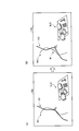
- FIG. 7 is a diagram for explaining an example of processing performed by the image processing system according to the first embodiment.
- the workstation 130 generates a parallax image group after estimating the state in the subject after the craniotomy
- the terminal device 140 generates the parallax image group generated by the workstation 130.
- the case of displaying will be described as an example.
- the terminal device 140 includes the stereoscopic display monitor 142, and displays the parallax image group generated by the workstation 130 on the stereoscopic display monitor 142. .
- the terminal device 140 displays a parallax image group indicating the head of the subject on the stereoscopic display monitor 142.
- the observer of the terminal device 140 can stereoscopically view the stereoscopic image I11 indicating the head of the subject.
- the terminal device 140 receives designation
- the workstation 130 estimates the state inside the head after the craniotomy. Specifically, the workstation 130 estimates the positional fluctuation of the brain, blood vessels, and the like inside the head when the craniotomy site K11 is opened. Then, the workstation 130 generates volume data after changing the positions of the brain, blood vessels, and the like based on the estimation result, and performs a rendering process on the volume data, thereby creating a new parallax image group. Is generated. Then, the workstation 130 transmits the newly generated parallax image group to the terminal device 140.
- the terminal device 140 displays the parallax image group received from the workstation 130 on the stereoscopic display monitor 142, so that the stereoscopic image showing the head of the subject after opening is displayed as in the example illustrated in FIG. 7B. I12 is displayed.
- an observer such as a doctor can stereoscopically view the state inside the head after craniotomy, and as a result, grasp the positional relationship of the brain, blood vessels, etc. whose position has changed by craniotomy before the operation. Is possible.
- the medical image diagnostic apparatus 110 is an X-ray CT apparatus
- the medical image diagnostic apparatus 110 may be an MRI apparatus or an ultrasonic diagnostic apparatus, and the CT value described in the following explanation is based on the intensity of an MR signal associated with each pulse sequence or the reflection of an ultrasonic wave. It may be wave data or the like.
- FIG. 8 is a diagram for explaining the terminal device 140 according to the first embodiment.
- the terminal device 140 according to the first embodiment includes an input unit 141, a stereoscopic display monitor 142, a communication unit 143, a storage unit 144, and a control unit 145.
- the input unit 141 is a pointing device such as a mouse or a trackball, or an information input device such as a keyboard, and receives input of various operations on the terminal device 140 from an operator.
- the input unit 141 accepts input of a patient ID, an examination ID, a device ID, a series ID, and the like for designating volume data for which the operator desires stereoscopic vision as a stereoscopic vision request.
- the input unit 141 according to the first embodiment accepts setting of an incision area that is an area for performing incision (craniotomy, thoracotomy, open abdomen, and the like) in a state where a stereoscopic image is displayed on the stereoscopic display monitor 142.
- the stereoscopic display monitor 142 is a liquid crystal panel or the like and displays various information. Specifically, the stereoscopic display monitor 142 according to the first embodiment displays a GUI (Graphical User Interface) for receiving various operations from the operator, a parallax image group, and the like.
- the stereoscopic display monitor 142 may be a stereoscopic display monitor (hereinafter referred to as a 2-parallax monitor) described with reference to FIGS. 2A and 2B, or a stereoscopic display monitor (hereinafter referred to as a 9-parallax monitor) described with reference to FIG. Described).
- a stereoscopic display monitor 142 is a nine-parallax monitor will be described.
- the communication unit 143 is a NIC (Network Interface Card) or the like, and communicates with other devices. Specifically, the communication unit 143 according to the first embodiment transmits the stereoscopic request received by the input unit 141 to the workstation 130. Further, the communication unit 143 according to the first embodiment receives a parallax image group transmitted by the workstation 130 in response to a stereoscopic request.
- NIC Network Interface Card
- the storage unit 144 is a hard disk, a semiconductor memory element, or the like, and stores various types of information. Specifically, the storage unit 144 according to the first embodiment stores a parallax image group acquired from the workstation 130 via the communication unit 143. The storage unit 144 also stores incidental information (number of parallaxes, resolution, volume space information, etc.) of the parallax image group acquired from the workstation 130 via the communication unit 143.
- the control unit 145 is an electronic circuit such as a CPU, MPU, or GPU, or an integrated circuit such as an ASIC or FPGA, and performs overall control of the terminal device 140.
- the control unit 145 controls transmission / reception of a stereoscopic request and a parallax image group performed with the workstation 130 via the communication unit 143.
- the control unit 145 controls storage of the parallax image group in the storage unit 144 and reading of the parallax image group from the storage unit 144.
- the control unit 145 includes a display control unit 1451 and a reception unit 1452 as illustrated in FIG.
- the display control unit 1451 displays the parallax image group received from the workstation 130 on the stereoscopic display monitor 142. Thereby, the parallax image group is displayed on the stereoscopic display monitor 142, and an observer of the stereoscopic display monitor 142 can observe a stereoscopically viewable stereoscopic image.
- the reception unit 1452 receives the setting of the incision region of the stereoscopic image displayed on the stereoscopic display monitor 142. Specifically, the reception unit 1452 in the first embodiment displays a stereoscopic image when a predetermined region of the stereoscopic image is designated as an incision region using the input unit 141 such as a pointing device. Coordinates of the incision region in the dimensional space (hereinafter sometimes referred to as “stereoscopic image space”) are received from the input unit 141. Then, the reception unit 1452 converts the coordinates of the incision region in the stereoscopic image space into coordinates in a space in which volume data is arranged (hereinafter sometimes referred to as “volume data space”) using a coordinate conversion formula described later. Convert. Then, the reception unit 1452 transmits the coordinates of the incision area in the volume data space to the workstation 130.
- stereoscopic image space Coordinates of the incision region in the dimensional space
- volume data space a space in which volume data is
- the reception unit 1452 acquires volume space information related to a three-dimensional space in which the volume data that is the generation source of the parallax image group is arranged as supplementary information related to the parallax image group from the workstation 130.
- the receiving unit 1452 sets the three-dimensional space indicated by the volume space information as the volume data space.
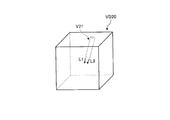
- FIG. 9 is a diagram illustrating an example of a correspondence relationship between the stereoscopic image space and the volume data space.
- FIG. 9A shows volume data
- FIG. 9B shows a stereoscopic image displayed by the stereoscopic display monitor 142.
- the coordinates 301, 302, and distance 303 in FIG. 9A correspond to the coordinates 304, 305, and distance 306 in FIG. 9B, respectively.
- Such correspondence between the stereoscopic image space coordinates and the volume data space coordinates is uniquely determined by the scale and parallax angle of the stereoscopic image, the line-of-sight direction (the line-of-sight direction during rendering or the line-of-sight direction during stereoscopic image observation), and the like. For example, it can be expressed in the following form (Equation 1).
- “x2”, “y2”, and “z2” respectively indicate stereoscopic image space coordinates.
- “X1”, “y1”, and “z1” indicate volume data space coordinates, respectively.
- the function “F” is a function that is uniquely determined by the scale, viewing angle, line-of-sight direction, and the like of the stereoscopic image. That is, the reception unit 1452 can acquire the correspondence between the stereoscopic image space coordinates and the volume data space coordinates by using (Equation 1).
- the function “F” is generated by the receiving unit 1452 every time the stereoscopic image scale, viewing angle, line-of-sight direction (line-of-sight direction during rendering or line-of-sight direction during stereoscopic image observation), and the like are changed.
- the affine transformation shown in (Expression 2) is used as the function “F” for transforming rotation, translation, enlargement, and reduction.
- the reception unit 1452 acquires the coordinates of the volume data space based on the function “F” is shown, but the present invention is not limited to this.
- the terminal device 140 has a coordinate table that is a table in which stereoscopic image space coordinates and volume data space coordinates are associated, and the reception unit 1452 searches the coordinate table using the stereoscopic image space coordinates as search keys.
- the volume data space coordinates corresponding to the stereoscopic image space coordinates may be acquired.
- FIG. 10 is a diagram for explaining a configuration example of the control unit 135 in the first embodiment.
- the control unit 135 of the workstation 130 includes an estimation unit 1351, a rendering control unit 1352, and a display control unit 1353.
- the estimation unit 1351 determines a voxel indicating the surface portion (skin, skull, muscle, etc.) of the subject among the voxels in the volume data located at the coordinates of the incision region received from the reception unit 1452. remove. For example, the estimation unit 1351 replaces the CT value of the voxel indicating the surface portion with a CT value indicating air. Then, after removing the surface portion, the estimation unit 1351 estimates the position variation of each voxel in the volume data based on various parameters (X1) to (X7) shown below.
- “position fluctuation” includes a voxel movement vector (movement direction and movement amount) and an expansion rate.
- the above (X1) will be described.
- Various organs in the subject are surrounded by surface portions such as bones and muscles existing on the surface of the subject and receive pressure from the surface portions.
- the brain before craniotomy is surrounded by the skull and is in a state of receiving pressure from the skull.
- the (X1) indicates the pressure applied to the inside of the subject (hereinafter may be referred to as “internal pressure”), and in the case of the above example, indicates the pressure applied to the brain due to the presence of the skull. Since various internal organs in the subject are not subjected to internal pressure from the surface portion when the surface portion is removed, they are easily moved in the direction of the removed surface portion and further easily expanded.
- the estimation unit 1351 uses the internal pressure (X1) when estimating the position variation of each voxel.
- the internal pressure applied to each part (voxel) is calculated in advance based on the distance between each part (voxel) and the surface part, the hardness of the surface part, and the like.
- the CT value is a value indicating the characteristics of the organ, and indicates, for example, the hardness of the organ.
- an organ with a higher CT value indicates a harder organ.
- the level of the CT value is an indicator of the amount of movement and the expansion rate of various organs.
- the estimation unit 1351 uses the (X2) CT value when estimating the position variation of each voxel.
- the estimation unit 1351 uses the CT value of the (X5) adjacent voxel when estimating the position variation of each voxel.
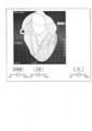
- the estimation unit 1351 of the workstation 130 estimates the movement vector and expansion rate of each voxel included in the volume data VD10.
- FIG. 11B not all the voxels are shown, but the estimation process by the estimation unit 1351 will be described using the volume data VD11 of the volume data VD10 as an example.
- one rectangle represents one voxel.
- a rectangle (voxel) that is shaded is a skull.
- the estimation unit 1351 replaces the voxels with diagonal lines above the incision region K11 shown in FIG. 11B with CT values such as air.
- the estimation unit 1351 estimates the movement vector and the expansion rate of each voxel using the movement estimation function calculated by the parameters (X1) to (X7) described above.
- the estimation unit 1351 calculates a function for movement estimation for each voxel using an internal pressure received from the voxel before being replaced with a CT value such as air.
- a CT value such as air.
- the estimation unit 1351 estimates that the entire voxel moves in the direction of the removed surface portion. Further, the estimation unit 1351 estimates that the movement amount is larger as the voxel is closer to the hatched voxel (skull), and the movement amount is smaller as the voxel is farther from the hatched voxel (skull). In the example shown in FIG. 11, each voxel seems to move in parallel with respect to the xy plane, but the estimation unit 1351 actually estimates the moving direction of each voxel in three dimensions.
- the estimation unit 1351 estimates a movement vector for each voxel included in the volume data VD10 as well as the volume data VD11. Furthermore, although not shown in FIG. 11, the estimation unit 1351 also estimates the expansion rate of each voxel.
- the rendering control unit 1352 generates a parallax image group from the volume data in cooperation with the rendering processing unit 136. Specifically, the rendering control unit 1352 according to the first embodiment generates volume data based on the estimation result by the estimation unit 1351, and performs a rendering process on the generated volume data. To control. At this time, the rendering control unit 1352 uses the movement vector of each voxel estimated by the estimation unit 1351 and the volume data that is the generation source of the parallax image group displayed on the stereoscopic display monitor 142 of the terminal device 140. New volume data is generated by reflecting the expansion rate. In the following description, the volume data reflecting the estimation result may be referred to as “virtual volume data”.
- the estimation unit 1351 estimates that the voxel V10 moves to a position between the voxel V11 and the voxel V12.
- the estimation unit 1351 estimates “2 times (200%)” as the expansion rate of the voxel V10.
- the rendering control unit 1352 arranges the voxel V10 at a position between the voxel V11 and the voxel V12, and doubles the size of the voxel V10.
- the rendering control unit 1352 arranges the voxel V10 in the voxel V11 and the voxel V12. In this way, the rendering control unit 1352 generates virtual volume data by changing the arrangement of each voxel based on the estimation result by the estimation unit 1351.
- the display control unit 1353 causes the stereoscopic display monitor 142 to display the parallax image group by transmitting the parallax image group generated by the rendering processing unit 136 to the terminal device 140.
- the display control unit 1353 in the first embodiment displays the parallax image group as a terminal device 140.
- the terminal device 140 displays a stereoscopic image I12 and the like showing the inside of the head after the head opening on the stereoscopic display monitor 142 as shown in FIG. 7B, for example.
- FIG. 12 is a sequence diagram illustrating an example of a processing flow by the image processing system according to the first embodiment.
- the terminal device 140 determines whether or not a stereoscopic view request is input from the observer (step S101).
- the terminal device 140 stands by.
- the terminal device 140 acquires a parallax image group corresponding to the stereoscopic request from the workstation 130 (step S102). Then, the display control unit 1451 displays the parallax image group acquired from the workstation 130 on the stereoscopic display monitor 142 (step S103).
- the reception unit 1452 of the terminal device 140 determines whether or not an incision region setting for the stereoscopic image displayed on the stereoscopic display monitor 142 has been received (step S104).
- the reception unit 1452 waits until the setting of the incision area is accepted.
- the accepting unit 1452 uses the function “F” described above to obtain the coordinates of the volume data space corresponding to the coordinates of the incision area in the stereoscopic image space.
- the acquired coordinates of the incision area in the acquired volume data space are transmitted to the workstation 130 (step S105).
- the estimation unit 1351 of the workstation 130 removes the voxels indicating the surface portion of the subject located at the coordinates of the incision region received from the terminal device 140, and based on the various parameters (X1) to (X7) and the like described above. Then, the position variation (movement vector and expansion rate) of each voxel in the volume data is estimated (step S106).
- the rendering control unit 1352 generates virtual volume data by reflecting the movement vector and expansion rate of each voxel estimated by the estimation unit 1351 in the volume data (step S107). Then, the rendering control unit 1352 generates a parallax image group by controlling the rendering processing unit 136 so as to perform rendering processing on the virtual volume data (step S108). Then, the display control unit 1353 transmits the parallax image group generated by the rendering processing unit 136 to the terminal device 140 (step S109).
- the display control unit 1451 of the terminal device 140 displays the parallax image group received from the workstation 130 on the stereoscopic display monitor 142 (step S110). Thereby, the stereoscopic display monitor 142 can display the stereoscopic image after the opening.
- 1st Embodiment is not restricted to said embodiment, Embodiment of the aspect containing the some modification shown below may be sufficient. Below, the modification of 1st Embodiment is demonstrated.
- the workstation 130 estimates the movement vectors and expansion rates of various organs based on the incision area designated by the observer. However, the workstation 130 may set incision areas at random, perform the estimation process by the estimation unit 1351 described above in each incision area, and transmit a parallax image group corresponding to each incision area to the terminal device 140. Then, the terminal device 140 may display the plurality of parallax image groups received from the workstation 130 on the stereoscopic display monitor 142 in parallel.
- the workstation 130 selects an incision region in which the average value of the movement amount and the expansion rate is lower than a predetermined threshold among the randomly set incision regions, and displays a parallax image group corresponding to the selected incision region. It may be transmitted to the device 140. Thereby, an observer such as a doctor can obtain an incision region having a small amount of movement and expansion rate of various organs even when craniotomy or the like is performed.
- the workstation 130 performs segmentation processing on the volume data to extract organs such as the heart, lungs, and blood vessels included in the volume data, and estimates the movement vector and the expansion rate for each extracted organ. May be. Then, when generating virtual volume data, the workstation 130 may perform control so that a group of voxels indicating the same organ is arranged at an adjacent position. That is, when generating virtual volume data, the workstation 130 arranges each voxel so that a stereoscopic image that is the same organ is not divided.
- the rendering control unit 1352 extracts only the voxel group estimated to move or expand by the estimation unit 1351, and volume data (hereinafter, “ A parallax image group may be generated from “specific volume data” in some cases.
- the stereoscopic display monitor 142 of the terminal device 140 displays a stereoscopic image showing only the part estimated to move or expand. Thereby, the observer can easily find a site that moves or expands.
- the rendering control unit 1352 may superimpose the parallax image group generated from the volume data before reflecting the estimation result and the parallax image group generated from the specific volume data.
- the stereoscopic display monitor 142 of the terminal device 140 displays a stereoscopic image in which the state inside the subject before opening and the state inside the subject after opening are superimposed. Thereby, the observer can easily find a site that moves or expands.
- the rendering control unit 1352 may color the voxel estimated to be moved or expanded by the estimation unit 1351 with a different color. At this time, the rendering control unit 1352 may change the color to be colored according to the movement amount or the expansion amount. In such a case, the stereoscopic display monitor 142 of the terminal device 140 displays a stereoscopic image in which a color different from usual is colored only on a portion estimated to move or expand. Thereby, the observer can easily find a site that moves or expands.
- the terminal device 240 receives operation which arrange
- the terminal device 240 accepts an operation of arranging the stereoscopic image Ic21 in a region indicating between the ribs in the stereoscopic image space in which the stereoscopic image I21 is displayed.
- the terminal device 240 transmits the coordinates of the volume data space corresponding to the position of the stereoscopic image space where the stereoscopic image Ic21 is arranged to the workstation 230.
- the workstation 230 When the workstation 230 receives the position of the stereoscopic image Ic21 from the terminal device 240, the workstation 230 estimates the state in the subject when the stereoscopic image Ic21 is inserted. Then, the workstation 230 generates virtual volume data reflecting the estimation result, and generates a new parallax image group by performing rendering processing on the generated virtual volume data. Then, the workstation 230 transmits the newly generated parallax image group to the terminal device 240.
- the terminal device 240 displays the group of parallax images received from the workstation 230 on the stereoscopic display monitor 142, so that the state in the subject into which the medical device is inserted is displayed as in the example illustrated in FIG.
- a stereoscopic image I22 shown and a stereoscopic image Ic22 showing a medical device inserted in the subject are displayed.
- an observer such as a doctor can stereoscopically view the state in the subject after insertion of the medical device, and as a result, grasps the positional relationship of various parts in the subject before the operation using the medical device. It becomes possible.
- the workstation 230 corresponds to the workstation 130 shown in FIG. 1, and the terminal device 240 is shown in FIG. This corresponds to the terminal device 140.
- the configuration of the terminal device 240 in the second embodiment is the same as the configuration example of the terminal device 140 shown in FIG.
- the control unit 245 included in the terminal device 240 according to the second embodiment performs processing different from the display control unit 1451 and the reception unit 1452 included in the control unit 145 illustrated in FIG. Therefore, the control unit 245 includes a display control unit 2451 instead of the display control unit 1451 included in the control unit 145, and includes a reception unit 2452 instead of the reception unit 1452.
- control unit 235 included in the workstation 230 in the second embodiment is the same as the configuration example of the control unit 135 illustrated in FIG.
- the control unit 235 in the second embodiment performs processing different from the estimation unit 1351 and the rendering control unit 1352 included in the control unit 135. Therefore, the control unit 235 includes an estimation unit 2351 instead of the estimation unit 1351 included in the control unit 135, and includes a rendering control unit 2352 instead of the rendering control unit 1352.
- a stereoscopic image indicating a subject may be referred to as a “subject stereoscopic image”
- a stereoscopic image indicating a medical device may be referred to as a “device stereoscopic image”.
- the display control unit 2451 of the terminal device 240 in the second embodiment displays the subject stereoscopic image and the device stereoscopic image on the stereoscopic display monitor 142 as in the example illustrated in FIG.
- the parallax image group for displaying the subject stereoscopic image is generated by the workstation 230, but the parallax image group for displaying the device stereoscopic image may be generated by the workstation 230 or a terminal. It may be generated by device 240.
- the workstation 230 may generate a parallax image group including both the subject and the medical device by superimposing the image of the medical device on the parallax image group of the subject.
- the terminal device 240 generates a parallax image group including both the subject and the medical device by superimposing the image of the medical device on the parallax image group of the subject generated by the workstation 230. Also good.
- the estimation unit 2351 of the workstation 230 receives the coordinates of the device stereoscopic image in the volume data space from the terminal device 240, the estimation unit 2351 estimates the position variation of each voxel included in the volume data. Specifically, the estimation unit 2351 assumes that the medical device is arranged at the position indicated by the coordinates of the device stereoscopic image received from the reception unit 2452, and based on various parameters (Y1) to (Y7) shown below. The position variation (movement vector and expansion coefficient) of each voxel in the volume data is estimated.
- the above (Y1) will be described.
- Various organs in the subject receive external force from the medical device when a medical device such as an endoscope or a scalpel is inserted. Specifically, various organs are pushed away from their original positions by the inserted medical device, and thus move in a direction away from the medical device. For this reason, the estimation unit 2351 uses the (Y1) external force when estimating the position variation of each voxel.
- the external force applied to each part (voxel) is calculated in advance based on the distance between each part (voxel) and the medical device, the type of medical device, and the like.
- the type of medical device here refers to an endoscope, a knife such as a knife, or the like.
- the type of medical device when the type of medical device is a blade, the organ is cut by the blade, so the amount of movement is small.
- the type of medical device is an endoscope
- the organ is moved to its original position by the endoscope. Since it is pushed out from, the amount of movement becomes large.
- the (Y2) CT value indicates the hardness of the organ, as described in (X2) above, and is therefore an indicator of the amount of movement and expansion rate of the organ itself. Further, the above (Y3) will be described.
- the larger the medical device the larger the region that occupies the subject, and the greater the amount of movement of the organ.
- an elongated and small medical device occupies a small area in the subject, and therefore the amount of movement of the organ is small.
- the estimation unit 2351 uses the size and shape of the medical device (Y3) when estimating the position variation of each voxel.
- the above (Y4) to (Y7) are the same as the above (X4) to (X7).
- the estimation unit 2351 in the second embodiment estimates the movement vector and the expansion rate of each voxel in the volume data using a function having the various parameters (Y1) to (Y7) as variables as described above.
- FIG. 14 is a diagram for describing an example of an estimation process performed by the estimation unit 2351 according to the second embodiment.
- the workstation 230 transmits the parallax image group generated from the volume data VD20 to the terminal device 240.
- the terminal device 240 displays the subject stereoscopic image and the device stereoscopic image illustrated in FIG. 13A on the stereoscopic display monitor 142 by displaying the parallax image group received from the workstation 230, An operation for moving the device stereoscopic image is received.
- the rendering control unit 2352 of the workstation 230 generates virtual volume data by reflecting the movement vector and the expansion rate of each voxel estimated by the estimation unit 2351 in the volume data, and generates the virtual volume data in the generated virtual volume data.
- the rendering processing unit 136 is controlled so as to perform the rendering process.
- the virtual volume data generation processing by the rendering control unit 2352 will be described using the example shown in FIG. As shown in FIG. 14 (B1), the rendering control unit 2352 first changes the arrangement of the voxels in the volume data VD20 based on the movement vector and the expansion rate of each voxel estimated by the estimation unit 2351. Furthermore, the rendering control unit 2352 replaces the CT value of the voxel in the voxel region V21 with a CT value indicating a medical device (metal or the like) as in a region D21 indicated by hatching in FIG. 14B2. . In this way, the rendering control unit 2352 generates virtual volume data.
- the parallax image group newly generated by the rendering processing unit 136 is transmitted to the terminal device 240 by the display control unit 1353.
- the display control unit 2451 of the terminal device 240 displays such a parallax image group on the stereoscopic display monitor 142, thereby, as shown in FIG. 13B, a stereoscopic image I22 including a stereoscopic image Ic22 indicating a medical device. Is displayed.
- the terminal device 240 determines whether or not a stereoscopic view request is input from the observer (step S201).
- the terminal device 240 stands by.
- the workstation 230 generates a parallax image group of the subject that does not include an image of the medical device, and transmits the generated parallax image group to the terminal device 240.
- the terminal device 240 generates a parallax image group including both the subject and the medical device by superimposing the image of the medical device on the parallax image group of the subject received from the workstation 230.
- the reception unit 2452 of the terminal device 240 determines whether or not an operation for arranging the device stereoscopic image in the stereoscopic image space in which the subject stereoscopic image displayed on the stereoscopic display monitor 142 is displayed has been received. (Step S204).
- the reception unit 2452 waits until the placement operation is received.
- the accepting unit 2452 accepts a device stereo image placement operation (Yes in step S204)
- the function “F” described above is used to correspond to the volume data space corresponding to the coordinates of the device stereo image in the stereo image space.
- the coordinates of the device stereoscopic image in the acquired volume data space are transmitted to the workstation 230 (step S205).
- the estimation unit 2351 of the workstation 230 assumes that the medical device is arranged at the coordinates of the device stereoscopic image received from the terminal device 240, and determines the volume based on the various parameters (Y1) to (Y7) and the like.
- the position variation (movement vector and expansion rate) of each voxel in the data is estimated (step S206).
- the rendering control unit 2352 generates virtual volume data by reflecting the movement vector and expansion rate of each voxel estimated by the estimation unit 2351 in the volume data (step S207). Then, the rendering control unit 2352 generates a parallax image group by controlling the rendering processing unit 136 to perform rendering processing on the virtual volume data (step S208). Then, the display control unit 1353 transmits the parallax image group generated by the rendering processing unit 136 to the terminal device 240 (step S209).
- 2nd Embodiment is not restricted to said embodiment, Embodiment of the aspect containing the some modification shown below may be sufficient. Below, the modification of 2nd Embodiment is demonstrated.
- the terminal device 240 may display a plurality of medical devices and allow the observer to select a medical device to be moved.
- the terminal device 240 may accept an operation of picking a blood vessel with a medical device such as tweezers, an operation of pulling a blood vessel, an operation of incising an organ surface with a scalpel or medical scissors, and the like.
- the workstation 230 extracts the blood vessel indicated by the stereoscopic image I31 and the blood vessel indicated by the stereoscopic image I41 as different blood vessels. That is, when generating virtual volume data, the workstation 230 arranges each voxel so that the stereoscopic image I31 and the stereoscopic image I32 that are the same organ are not divided. In a state in which such a stereoscopic image is displayed, the observer selects a desired medical device from the stereoscopic image Ic31 using a pointing device or the like, so that the medical device can select the stereoscopic image I31 or I41. Various operations can be performed.
- the rendering control unit 2352 estimates the position variation for each organ based on the function set in the tweezers and the various parameters (Y1) to (Y7) described above, and generates virtual volume data. .
- the rendering control unit 2352 does not move only the stereoscopic image I31 operated by tweezers, but moves other organs (such as blood vessels indicated by the stereoscopic image I41) as the blood vessels indicated by the stereoscopic image I31 move.
- the terminal device 240 By displaying the parallax image group generated from such virtual volume data, the terminal device 240 observes the stereoscopic image I32 indicating the blood vessel after movement as in the example illustrated in FIG. Furthermore, it is possible to observe the stereoscopic image I42 showing the blood vessel affected by the movement of the blood vessel. Further, since the observer can move the stereoscopic image for each organ even when a plurality of stereoscopic images are overlapped, an aneurysm W or the like as in the example shown in FIG. Can be found.
- FIG. 13B the example in which the appearance inside the subject into which a medical device such as an endoscope is inserted is displayed as a stereoscopic image has been described.
- the stereoscopic image of the endoscope is arranged in the subject as in the example illustrated in FIG. 13
- the stereoscopic image in the subject viewed from the endoscope is displayed together with the appearance of the subject. May be displayed.
- an endoscope is used by using a virtual endoscopy (VE) display method widely used as a display method (CTC: CT Colonography) of a three-dimensional X-ray CT image obtained by imaging the large intestine or the like.
- VE virtual endoscopy
- CTC CT Colonography
- the rendering control unit 2352 generates a parallax image group using the nine viewpoint positions L1 to L9 positioned at the distal end portion of the virtual endoscope as rendering conditions. Then, the workstation 230 transmits, to the terminal device 240, a parallax image group that shows the appearance inside the subject, together with the parallax image group viewed from the virtual endoscope.
- the terminal device 240 as in the example illustrated in FIG. 18, has a three-dimensional image in the subject viewed from the virtual endoscope as well as the appearance in the subject in which the device stereoscopic image (endoscope) Ic21 is inserted.
- the image I51 can be displayed. As a result, the observer can confirm before the operation what kind of image is projected on the endoscope when the endoscope is inserted.
- the terminal device 240 in the second embodiment may accept an operation of injecting air after an operation of inserting the endoscope into the subject.
- the terminal device 240 receives an operation for injecting air, the terminal device 240 notifies the workstation 230 that the operation has been received.
- the workstation 230 notified from the terminal device 240 assumes that air has been injected from the distal end of the endoscope, and based on the various parameters (Y1) to (Y7) and the like, Virtual volume data is generated by estimating the position variation (movement vector and expansion rate) of the voxel. Then, the workstation 230 generates a parallax image group by performing rendering processing on the virtual volume data, and transmits the generated parallax image group to the terminal device 240. As a result, the terminal device 240 can display a three-dimensional image indicating a state inside the subject into which air has been injected from the endoscope after insertion of the endoscope.
- FIG. 19 is a diagram for explaining a modification of the second embodiment.
- the terminal device 240 displays a control bar capable of setting an opacity for each part.
- the terminal device 240 superimposes the control bar image on the parallax image group.
- the terminal device 240 transmits the changed opacity for each organ to the workstation 230.
- the workstation 230 performs rendering processing on the volume data based on the opacity for each organ received from the terminal device 240, and transmits the generated parallax image group to the terminal device 240.
- the terminal device 240 can display a three-dimensional image that can change the opacity of each organ. Note that what can be changed for each organ is not limited to opacity, and the terminal device 240 may change the color density and the like for each organ using the control bar as in the above example.
- FIG. 20 is a diagram for explaining a modification of the second embodiment.
- the workstation 230 for example, automatically reduces the opacity of the voxel located in the vicinity of the voxel region V21, and then performs the rendering process on the volume data VD20. I do. Accordingly, the terminal device 240 displays a stereoscopic image in which the area A10 in the vicinity of the medical device is transparent, as in the example illustrated in FIG. As a result, the observer can accurately observe the influence on the surrounding organs when the medical device is inserted.
- the medical image diagnostic apparatus is an X-ray CT apparatus
- the medical image diagnostic apparatus may be an MRI apparatus or an ultrasonic diagnostic apparatus.
- (X2) CT value, (X5) CT value of adjacent voxel, (Y2) CT value, (Y5) CT value of adjacent voxel, and the like described above are the intensity of MR signal associated with each pulse sequence, It may be ultrasonic reflected wave data or the like.
- the medical image diagnostic apparatus is an MRI apparatus, an ultrasonic diagnostic apparatus or the like, the elastic modulus (hardness) of the living tissue is measured in a state in which the living tissue is compressed from the outside, and elastography (Elastography) is performed.
- the medical image diagnostic apparatus is an MRI apparatus, an ultrasonic diagnostic apparatus, or the like
- the estimation unit 1351 and the estimation unit 2351 described above perform various parameters (X1) to (X7) and (Y1) to (Y In addition to Y7), the position variation of each voxel in the volume data may be estimated based on the elastic modulus (hardness) of the living tissue obtained by elastography.
- the terminal device 140 or 240 acquires the parallax image group corresponding to the movement of the own device or the movement of the observation position from the workstation 130 or 230.
- the terminal device 140 has the same functions as the control unit 135 and the rendering processing unit 136 of the workstation 130
- the terminal device 240 has the same functions as the control unit 235 and the rendering processing unit 136 of the workstation 230. You may have.
- the terminal device 140 or 240 acquires volume data from the image storage device 120 and performs the same processing as the control unit 135 or 235 described above.
- each component of each illustrated apparatus is functionally conceptual and does not necessarily need to be physically configured as illustrated. That is, the specific form of distribution / integration of each device is not limited to the one shown in the figure, and all or a part of the distribution / integration may be functionally or physically distributed in arbitrary units according to various loads or usage conditions. Can be integrated and configured.
- the control unit 135 of the workstation 130 may be connected as an external device of the workstation 130 via a network.
Abstract
Le système de traitement d'image (1) ci-décrit comprend une unité de réception (1452), une unité d'estimation (1351), une unité de traitement de rendu (136), et une unité de commande d'affichage (1353). L'unité de réception (1452) reçoit la commande permettant de conférer une force virtuelle à un sujet représenté par une image tridimensionnelle. L'unité d'estimation (1351) estime la variation de position d'un groupe de voxels contenu dans un ensemble de données volumétriques sur la base de la force reçue par l'intermédiaire de l'unité de réception (1452). L'unité de traitement de rendu (136) modifie l'agencement du groupe de voxels contenu dans l'ensemble de données volumétriques sur la base du résultat d'estimation de l'unité d'estimation (1351) et génère un groupe d'images parallaxes par soumission de l'ensemble de données volumétriques modifié au traitement de rendu. L'unité de commande d'affichage (1451) affiche le groupe d'images parallaxes qui vient d'être généré par l'intermédiaire de l'unité de traitement de rendu (136) sur un dispositif d'affichage tridimensionnel (142).
Priority Applications (2)
| Application Number | Priority Date | Filing Date | Title |
|---|---|---|---|
| CN201280003495.2A CN103200871B (zh) | 2011-07-19 | 2012-07-19 | 图像处理系统、装置、方法以及医用图像诊断装置 |
| US14/158,352 US20140132605A1 (en) | 2011-07-19 | 2014-01-17 | System, apparatus, and method for image processing and medical image diagnosis apparatus |
Applications Claiming Priority (2)
| Application Number | Priority Date | Filing Date | Title |
|---|---|---|---|
| JP2011-158226 | 2011-07-19 | ||
| JP2011158226A JP5984235B2 (ja) | 2011-07-19 | 2011-07-19 | 画像処理システム、装置、方法及び医用画像診断装置 |
Related Child Applications (1)
| Application Number | Title | Priority Date | Filing Date |
|---|---|---|---|
| US14/158,352 Continuation US20140132605A1 (en) | 2011-07-19 | 2014-01-17 | System, apparatus, and method for image processing and medical image diagnosis apparatus |
Publications (1)
| Publication Number | Publication Date |
|---|---|
| WO2013012042A1 true WO2013012042A1 (fr) | 2013-01-24 |
Family
ID=47558217
Family Applications (1)
| Application Number | Title | Priority Date | Filing Date |
|---|---|---|---|
| PCT/JP2012/068371 WO2013012042A1 (fr) | 2011-07-19 | 2012-07-19 | Système, dispositif et procédé de traitement d'image, et dispositif de diagnostic par imagerie médicale |
Country Status (4)
| Country | Link |
|---|---|
| US (1) | US20140132605A1 (fr) |
| JP (1) | JP5984235B2 (fr) |
| CN (1) | CN103200871B (fr) |
| WO (1) | WO2013012042A1 (fr) |
Families Citing this family (11)
| Publication number | Priority date | Publication date | Assignee | Title |
|---|---|---|---|---|
| JP6042711B2 (ja) * | 2012-12-18 | 2016-12-14 | 富士フイルム株式会社 | トロカーポート位置決定支援装置、トロカーポート位置決定支援プログラムおよびトロカーポート位置決定支援装置の作動方法 |
| JP2014206893A (ja) * | 2013-04-15 | 2014-10-30 | ソニー株式会社 | 画像処理装置と画像処理方法およびプログラム |
| US10143381B2 (en) * | 2013-04-19 | 2018-12-04 | Canon Kabushiki Kaisha | Object information acquiring apparatus and control method therefor |
| US10613176B2 (en) * | 2014-05-19 | 2020-04-07 | The United States Of America, As Represented By The Secretary, Department Of Health And Human Services | Magnetic resonance 2D relaxometry reconstruction using partial data |
| JP2015220643A (ja) * | 2014-05-19 | 2015-12-07 | 株式会社東芝 | 立体観察装置 |
| JP6336930B2 (ja) * | 2015-02-16 | 2018-06-06 | 富士フイルム株式会社 | 仮想オブジェクト表示装置、方法、プログラムおよびシステム |
| US10342633B2 (en) * | 2016-06-20 | 2019-07-09 | Toshiba Medical Systems Corporation | Medical image data processing system and method |
| US10299699B2 (en) * | 2016-11-28 | 2019-05-28 | Biosense Webster (Israel) Ltd. | Computerized tomography image correction |
| US9892564B1 (en) * | 2017-03-30 | 2018-02-13 | Novarad Corporation | Augmenting real-time views of a patient with three-dimensional data |
| KR102083558B1 (ko) | 2018-10-23 | 2020-03-02 | 김지원 | 복셀리곤을 이용한 3차원 객체 모델링 방법 및 프로그램 |
| JP7331524B2 (ja) * | 2019-07-24 | 2023-08-23 | 富士フイルムビジネスイノベーション株式会社 | 情報処理装置及びプログラム |
Citations (7)
| Publication number | Priority date | Publication date | Assignee | Title |
|---|---|---|---|---|
| JPH0437405U (fr) * | 1990-07-27 | 1992-03-30 | ||
| JPH11175767A (ja) * | 1997-09-19 | 1999-07-02 | Mitsubishi Electric Inf Technol Center America Inc | コンピュータにおけるグラフィック表現生成方法 |
| JP2003210386A (ja) * | 2002-01-24 | 2003-07-29 | Olympus Optical Co Ltd | 内視鏡シミュレータシステム |
| JP2003339703A (ja) * | 2003-05-26 | 2003-12-02 | Olympus Optical Co Ltd | 超音波画像信号処理装置及び超音波画像信号処理システム |
| JP2006101329A (ja) * | 2004-09-30 | 2006-04-13 | Kddi Corp | 立体視画像観察装置ならびにその共有サーバ、クライアント端末およびピア・ツー・ピア端末、レンダリング画像生成方法および立体視画像表示方法ならびにそのプログラムおよび記憶媒体 |
| WO2007015365A1 (fr) * | 2005-08-01 | 2007-02-08 | National University Corporation NARA Institute of Science and Technology | Dispositif et programme de traitement d'informations |
| JP2008029415A (ja) * | 2006-07-26 | 2008-02-14 | Hitachi Medical Corp | 医療画像装置 |
Family Cites Families (10)
| Publication number | Priority date | Publication date | Assignee | Title |
|---|---|---|---|---|
| JP2002092656A (ja) * | 2000-09-11 | 2002-03-29 | Canon Inc | 立体画像表示装置及び画像データの表示方法 |
| US7376903B2 (en) * | 2004-06-29 | 2008-05-20 | Ge Medical Systems Information Technologies | 3D display system and method |
| DE102005029903A1 (de) * | 2005-06-25 | 2007-01-04 | Universitätsklinikum Hamburg-Eppendorf | Verfahren und Vorrichtung zur 3D-Navigation auf Schichtbildern |
| US8500451B2 (en) * | 2007-01-16 | 2013-08-06 | Simbionix Ltd. | Preoperative surgical simulation |
| CN101320526B (zh) * | 2008-07-11 | 2010-12-22 | 深圳先进技术研究院 | 一种手术预测和训练的设备及其方法 |
| US8374723B2 (en) * | 2008-12-31 | 2013-02-12 | Intuitive Surgical Operations, Inc. | Obtaining force information in a minimally invasive surgical procedure |
| US20100178644A1 (en) * | 2009-01-15 | 2010-07-15 | Simquest Llc | Interactive simulation of biological tissue |
| CN102117378B (zh) * | 2009-12-31 | 2012-07-25 | 苏州瑞派宁科技有限公司 | 一种基于三维多模影像的肝肿瘤综合手术规划模拟方法及其系统 |
| US20110213342A1 (en) * | 2010-02-26 | 2011-09-01 | Ashok Burton Tripathi | Real-time Virtual Indicium Apparatus and Methods for Guiding an Implant into an Eye |
| CN101976298B (zh) * | 2010-09-27 | 2012-06-27 | 南京信息工程大学 | 增强力触觉再现的对称式板弹簧虚拟模型的建模方法 |
-
2011
- 2011-07-19 JP JP2011158226A patent/JP5984235B2/ja active Active
-
2012
- 2012-07-19 WO PCT/JP2012/068371 patent/WO2013012042A1/fr active Application Filing
- 2012-07-19 CN CN201280003495.2A patent/CN103200871B/zh active Active
-
2014
- 2014-01-17 US US14/158,352 patent/US20140132605A1/en not_active Abandoned
Patent Citations (7)
| Publication number | Priority date | Publication date | Assignee | Title |
|---|---|---|---|---|
| JPH0437405U (fr) * | 1990-07-27 | 1992-03-30 | ||
| JPH11175767A (ja) * | 1997-09-19 | 1999-07-02 | Mitsubishi Electric Inf Technol Center America Inc | コンピュータにおけるグラフィック表現生成方法 |
| JP2003210386A (ja) * | 2002-01-24 | 2003-07-29 | Olympus Optical Co Ltd | 内視鏡シミュレータシステム |
| JP2003339703A (ja) * | 2003-05-26 | 2003-12-02 | Olympus Optical Co Ltd | 超音波画像信号処理装置及び超音波画像信号処理システム |
| JP2006101329A (ja) * | 2004-09-30 | 2006-04-13 | Kddi Corp | 立体視画像観察装置ならびにその共有サーバ、クライアント端末およびピア・ツー・ピア端末、レンダリング画像生成方法および立体視画像表示方法ならびにそのプログラムおよび記憶媒体 |
| WO2007015365A1 (fr) * | 2005-08-01 | 2007-02-08 | National University Corporation NARA Institute of Science and Technology | Dispositif et programme de traitement d'informations |
| JP2008029415A (ja) * | 2006-07-26 | 2008-02-14 | Hitachi Medical Corp | 医療画像装置 |
Non-Patent Citations (4)
| Title |
|---|
| MEGUMI NAKAO: "Supporting Surgical Planning with Simulation of Tissue Cutting and Opening Incision", TRANSACTIONS OF THE VIRTUAL REALITY SOCIETY OF JAPAN, vol. 8, no. 2, 30 June 2003 (2003-06-30), pages 163 - 170 * |
| NAOKI SUZUKI: "Virtual Surgery System for Interactive Surgical Simulation", THE SEVENTH INTERNATIONAL CONFERENCE ON ARTIFICIAL AND REALITY AND TELE-EXISTENCE ICAT'97, 25 June 1999 (1999-06-25), pages 129 - 134 * |
| RYO MOCHIZUKI: "Hivision-Computer Aided Surgery system and Virtual Hospital", ITE TECHNICAL REPORT, vol. 23, no. 70, 17 November 1999 (1999-11-17), pages 55 - 60 * |
| TAKEYA FUKUNAGA: "Usefulness of Volume Rendering Stereo-movie in Neurosurgical Craniotomies", JAPANESE JOURNAL OF RADIOLOGICAL TECHNOLOGY, vol. 63, no. 12, 20 December 2007 (2007-12-20), pages 1370 - 1376 * |
Also Published As
| Publication number | Publication date |
|---|---|
| JP5984235B2 (ja) | 2016-09-06 |
| JP2013022156A (ja) | 2013-02-04 |
| US20140132605A1 (en) | 2014-05-15 |
| CN103200871A (zh) | 2013-07-10 |
| CN103200871B (zh) | 2015-07-01 |
Similar Documents
| Publication | Publication Date | Title |
|---|---|---|
| JP5984235B2 (ja) | 画像処理システム、装置、方法及び医用画像診断装置 | |
| JP5909055B2 (ja) | 画像処理システム、装置、方法及びプログラム | |
| JP6058290B2 (ja) | 画像処理システム、装置、方法及び医用画像診断装置 | |
| JP5808146B2 (ja) | 画像処理システム、装置及び方法 | |
| JP6058306B2 (ja) | 画像処理システム、装置、方法及び医用画像診断装置 | |
| JP5818531B2 (ja) | 画像処理システム、装置及び方法 | |
| JP6058286B2 (ja) | 医用画像診断装置、医用画像処理装置及び方法 | |
| JP5972533B2 (ja) | 画像処理システム及び方法 | |
| JP6430149B2 (ja) | 医用画像処理装置 | |
| JP6147464B2 (ja) | 画像処理システム、端末装置及び方法 | |
| US9445082B2 (en) | System, apparatus, and method for image processing | |
| JP5173053B2 (ja) | 画像処理システム、装置、方法及び医用画像診断装置 | |
| JP6017124B2 (ja) | 画像処理システム、画像処理装置、医用画像診断装置、画像処理方法及び画像処理プログラム | |
| JP6104982B2 (ja) | 画像処理装置、画像処理方法及び医用画像診断装置 | |
| JP5835975B2 (ja) | 画像処理システム、装置、方法及び医用画像診断装置 | |
| JP5813986B2 (ja) | 画像処理システム、装置、方法及びプログラム | |
| JP5974235B2 (ja) | 画像処理装置、画像処理方法、画像処理システム及び医用画像診断装置 | |
| Eck et al. | Display technologies | |
| JP5868051B2 (ja) | 画像処理装置、画像処理方法、画像処理システム及び医用画像診断装置 | |
| JP6087618B2 (ja) | 画像処理システムおよび画像処理方法 | |
| JP2013013552A (ja) | 医用画像診断装置、医用画像処理装置及び方法 |
Legal Events
| Date | Code | Title | Description |
|---|---|---|---|
| 121 | Ep: the epo has been informed by wipo that ep was designated in this application |
Ref document number: 12815002 Country of ref document: EP Kind code of ref document: A1 |
|
| NENP | Non-entry into the national phase |
Ref country code: DE |
|
| 122 | Ep: pct application non-entry in european phase |
Ref document number: 12815002 Country of ref document: EP Kind code of ref document: A1 |