WO2013012042A1 - Image processing system, device and method, and medical image diagnostic device - Google Patents
Image processing system, device and method, and medical image diagnostic device Download PDFInfo
- Publication number
- WO2013012042A1 WO2013012042A1 PCT/JP2012/068371 JP2012068371W WO2013012042A1 WO 2013012042 A1 WO2013012042 A1 WO 2013012042A1 JP 2012068371 W JP2012068371 W JP 2012068371W WO 2013012042 A1 WO2013012042 A1 WO 2013012042A1
- Authority
- WO
- WIPO (PCT)
- Prior art keywords
- image
- volume data
- unit
- stereoscopic
- parallax
- Prior art date
Links
Images


Classifications
-
- G—PHYSICS
- G06—COMPUTING; CALCULATING OR COUNTING
- G06T—IMAGE DATA PROCESSING OR GENERATION, IN GENERAL
- G06T15/00—3D [Three Dimensional] image rendering
- G06T15/08—Volume rendering
-
- A—HUMAN NECESSITIES
- A61—MEDICAL OR VETERINARY SCIENCE; HYGIENE
- A61B—DIAGNOSIS; SURGERY; IDENTIFICATION
- A61B6/00—Apparatus for radiation diagnosis, e.g. combined with radiation therapy equipment
- A61B6/46—Apparatus for radiation diagnosis, e.g. combined with radiation therapy equipment with special arrangements for interfacing with the operator or the patient
- A61B6/461—Displaying means of special interest
- A61B6/466—Displaying means of special interest adapted to display 3D data
-
- G—PHYSICS
- G06—COMPUTING; CALCULATING OR COUNTING
- G06T—IMAGE DATA PROCESSING OR GENERATION, IN GENERAL
- G06T19/00—Manipulating 3D models or images for computer graphics
- G06T19/20—Editing of 3D images, e.g. changing shapes or colours, aligning objects or positioning parts
-
- A—HUMAN NECESSITIES
- A61—MEDICAL OR VETERINARY SCIENCE; HYGIENE
- A61B—DIAGNOSIS; SURGERY; IDENTIFICATION
- A61B90/00—Instruments, implements or accessories specially adapted for surgery or diagnosis and not covered by any of the groups A61B1/00 - A61B50/00, e.g. for luxation treatment or for protecting wound edges
- A61B90/36—Image-producing devices or illumination devices not otherwise provided for
- A61B90/37—Surgical systems with images on a monitor during operation
- A61B2090/372—Details of monitor hardware
-
- A—HUMAN NECESSITIES
- A61—MEDICAL OR VETERINARY SCIENCE; HYGIENE
- A61B—DIAGNOSIS; SURGERY; IDENTIFICATION
- A61B90/00—Instruments, implements or accessories specially adapted for surgery or diagnosis and not covered by any of the groups A61B1/00 - A61B50/00, e.g. for luxation treatment or for protecting wound edges
- A61B90/50—Supports for surgical instruments, e.g. articulated arms
- A61B2090/502—Headgear, e.g. helmet, spectacles
-
- G—PHYSICS
- G01—MEASURING; TESTING
- G01R—MEASURING ELECTRIC VARIABLES; MEASURING MAGNETIC VARIABLES
- G01R33/00—Arrangements or instruments for measuring magnetic variables
- G01R33/20—Arrangements or instruments for measuring magnetic variables involving magnetic resonance
- G01R33/44—Arrangements or instruments for measuring magnetic variables involving magnetic resonance using nuclear magnetic resonance [NMR]
- G01R33/48—NMR imaging systems
- G01R33/54—Signal processing systems, e.g. using pulse sequences ; Generation or control of pulse sequences; Operator console
- G01R33/56—Image enhancement or correction, e.g. subtraction or averaging techniques, e.g. improvement of signal-to-noise ratio and resolution
- G01R33/5608—Data processing and visualization specially adapted for MR, e.g. for feature analysis and pattern recognition on the basis of measured MR data, segmentation of measured MR data, edge contour detection on the basis of measured MR data, for enhancing measured MR data in terms of signal-to-noise ratio by means of noise filtering or apodization, for enhancing measured MR data in terms of resolution by means for deblurring, windowing, zero filling, or generation of gray-scaled images, colour-coded images or images displaying vectors instead of pixels
-
- G—PHYSICS
- G06—COMPUTING; CALCULATING OR COUNTING
- G06T—IMAGE DATA PROCESSING OR GENERATION, IN GENERAL
- G06T2210/00—Indexing scheme for image generation or computer graphics
- G06T2210/41—Medical
-
- G—PHYSICS
- G06—COMPUTING; CALCULATING OR COUNTING
- G06T—IMAGE DATA PROCESSING OR GENERATION, IN GENERAL
- G06T2219/00—Indexing scheme for manipulating 3D models or images for computer graphics
- G06T2219/20—Indexing scheme for editing of 3D models
- G06T2219/2021—Shape modification
-
- H—ELECTRICITY
- H04—ELECTRIC COMMUNICATION TECHNIQUE
- H04N—PICTORIAL COMMUNICATION, e.g. TELEVISION
- H04N13/00—Stereoscopic video systems; Multi-view video systems; Details thereof
- H04N13/30—Image reproducers
- H04N13/302—Image reproducers for viewing without the aid of special glasses, i.e. using autostereoscopic displays
- H04N13/305—Image reproducers for viewing without the aid of special glasses, i.e. using autostereoscopic displays using lenticular lenses, e.g. arrangements of cylindrical lenses
-
- H—ELECTRICITY
- H04—ELECTRIC COMMUNICATION TECHNIQUE
- H04N—PICTORIAL COMMUNICATION, e.g. TELEVISION
- H04N13/00—Stereoscopic video systems; Multi-view video systems; Details thereof
- H04N13/30—Image reproducers
- H04N13/349—Multi-view displays for displaying three or more geometrical viewpoints without viewer tracking
- H04N13/351—Multi-view displays for displaying three or more geometrical viewpoints without viewer tracking for displaying simultaneously
Landscapes
- Engineering & Computer Science (AREA)
- Physics & Mathematics (AREA)
- Health & Medical Sciences (AREA)
- Life Sciences & Earth Sciences (AREA)
- Computer Graphics (AREA)
- General Physics & Mathematics (AREA)
- Theoretical Computer Science (AREA)
- Medical Informatics (AREA)
- Optics & Photonics (AREA)
- Biomedical Technology (AREA)
- Software Systems (AREA)
- General Engineering & Computer Science (AREA)
- Biophysics (AREA)
- High Energy & Nuclear Physics (AREA)
- Computer Hardware Design (AREA)
- Nuclear Medicine, Radiotherapy & Molecular Imaging (AREA)
- Architecture (AREA)
- Pathology (AREA)
- Radiology & Medical Imaging (AREA)
- Human Computer Interaction (AREA)
- Heart & Thoracic Surgery (AREA)
- Molecular Biology (AREA)
- Surgery (AREA)
- Animal Behavior & Ethology (AREA)
- General Health & Medical Sciences (AREA)
- Public Health (AREA)
- Veterinary Medicine (AREA)
- Apparatus For Radiation Diagnosis (AREA)
- Magnetic Resonance Imaging Apparatus (AREA)
- Ultra Sonic Daignosis Equipment (AREA)
- Testing, Inspecting, Measuring Of Stereoscopic Televisions And Televisions (AREA)
- Measuring And Recording Apparatus For Diagnosis (AREA)
Abstract
This image processing system (1) is provided with a reception unit (1452), an estimation unit (1351), a rendering processing unit (136), and a display control unit (1353). The reception unit (1452) receives the operation to impart virtual force to a subject represented by a three-dimensional image. The estimation unit (1351) estimates the position variation of a voxel group contained in a set of volume data on the basis of the force received by means of the reception unit (1452). The rendering processing unit (136) modifies the arrangement of the voxel group contained in the set of volume data on the basis of the estimation result of the estimation unit (1351) and newly generates a parallax image group by subjecting the modified set of volume data to rendering processing. The display control unit (1451) displays the parallax image group that was newly generated by means of the rendering processing unit (136) onto a three-dimensional display device (142).
Description
本発明の実施形態は、画像処理システム、装置、方法及び医用画像診断装置に関する。
Embodiments described herein relate generally to an image processing system, apparatus, method, and medical image diagnostic apparatus.
従来、2つの視点から撮影された2つの画像をモニタに表示することで、立体視用メガネ等の専用機器を用いた利用者にとって立体視可能な画像を表示する技術が知られている。また、近年、レンチキュラーレンズ等の光線制御子を用いて、複数の視点から撮影された画像(例えば、9つの画像)をモニタに表示することで、裸眼の利用者にとっても立体視可能な画像を表示する技術が知られている。なお、立体視可能なモニタにて表示される複数の画像は、1視点から撮影された画像の奥行き情報を推定し、推定した情報を用いた画像処理により生成される場合もある。
Conventionally, a technique for displaying a stereoscopically visible image for a user using dedicated equipment such as stereoscopic glasses by displaying two images captured from two viewpoints on a monitor is known. In recent years, an image captured from a plurality of viewpoints (for example, nine images) is displayed on a monitor using a light controller such as a lenticular lens, so that an image that can be stereoscopically viewed by a naked-eye user can be obtained. A technique for displaying is known. Note that a plurality of images displayed on a stereoscopically visible monitor may be generated by estimating depth information of an image taken from one viewpoint and performing image processing using the estimated information.
一方、X線CT(Computed Tomography)装置やMRI(Magnetic Resonance Imaging)装置、超音波診断装置等の医用画像診断装置では、3次元の医用画像データ(以下、ボリュームデータ)を生成可能な装置が実用化されている。かかる医用画像診断装置は、ボリュームデータに対して種々の画像処理を実行することで表示用の平面画像を生成し、汎用モニタ上に表示する。例えば、医用画像診断装置は、ボリュームデータに対してボリュームレンダリング処理を実行することで、被検体についての3次元の情報が反映された2次元のレンダリング画像を生成し、生成したレンダリング画像を汎用モニタ上に表示する。
On the other hand, in medical image diagnostic apparatuses such as X-ray CT (Computed Tomography) apparatuses, MRI (Magnetic Resonance Imaging) apparatuses, and ultrasonic diagnostic apparatuses, apparatuses capable of generating three-dimensional medical image data (hereinafter referred to as volume data) are practical. It has become. Such a medical image diagnostic apparatus generates a planar image for display by executing various image processing on the volume data, and displays it on a general-purpose monitor. For example, the medical image diagnostic apparatus generates a two-dimensional rendering image in which three-dimensional information about the subject is reflected by performing volume rendering processing on the volume data, and the generated rendering image is displayed on the general-purpose monitor. Display above.
本発明が解決しようとする課題は、術中における被検体内の立体画像を術前に表示することができる画像処理システム、装置、方法及び医用画像診断装置を提供することである。
The problem to be solved by the present invention is to provide an image processing system, apparatus, method, and medical image diagnostic apparatus capable of displaying a stereoscopic image in a subject during surgery before surgery.
実施形態に係る画像処理システムは、受付部と、推定部と、レンダリング処理部と、表示制御部とを備える。受付部は、立体画像が示す被検体に仮想的な力を加える操作を受け付ける。推定部は、前記受付部によって受け付けられた力に基づいて、ボリュームデータに含まれるボクセル群の位置変動を推定する。レンダリング処理部は、前記推定部による推定結果に基づいて、前記ボリュームデータに含まれるボクセル群の配置を変更し、変更後のボリュームデータに対してレンダリング処理を行うことにより視差画像群を新たに生成する。表示制御部は、前記レンダリング処理部によって新たに生成された視差画像群を立体表示装置に表示させる。
The image processing system according to the embodiment includes a reception unit, an estimation unit, a rendering processing unit, and a display control unit. The accepting unit accepts an operation of applying a virtual force to the subject indicated by the stereoscopic image. The estimation unit estimates the position variation of the voxel group included in the volume data based on the force received by the reception unit. The rendering processing unit generates a new parallax image group by changing the arrangement of the voxel groups included in the volume data based on the estimation result by the estimation unit and performing the rendering process on the changed volume data. To do. The display control unit causes the stereoscopic display device to display the parallax image group newly generated by the rendering processing unit.
以下、添付図面を参照して、画像処理システム、装置、方法及び医用画像診断装置の実施形態を詳細に説明する。なお、以下では、画像処理装置としての機能を有するワークステーションを含む画像処理システムを実施形態として説明する。ここで、以下の実施形態で用いる用語について説明すると、「視差画像群」とは、ボリュームデータに対して、所定の視差角ずつ視点位置を移動させてボリュームレンダリング処理を行うことで生成された画像群のことである。すなわち、「視差画像群」は、「視点位置」が異なる複数の「視差画像」から構成される。また、「視差角」とは、「視差画像群」を生成するために設定された各視点位置のうち隣接する視点位置とボリュームデータによって表される空間内の所定位置(例えば、空間の中心)とにより定まる角度のことである。また、「視差数」とは、立体表示モニタにて立体視されるために必要となる「視差画像」の数のことである。また、以下で記載する「9視差画像」とは、9つの「視差画像」から構成される「視差画像群」のことである。また、以下で記載する「2視差画像」とは、2つの「視差画像」から構成される「視差画像群」のことである。
Hereinafter, embodiments of an image processing system, apparatus, method, and medical image diagnostic apparatus will be described in detail with reference to the accompanying drawings. In the following, an image processing system including a workstation having a function as an image processing apparatus will be described as an embodiment. Here, the terms used in the following embodiments will be described. The “parallax image group” is an image generated by performing volume rendering processing by moving the viewpoint position by a predetermined parallax angle with respect to volume data. It is a group. That is, the “parallax image group” includes a plurality of “parallax images” having different “viewpoint positions”. The “parallax angle” is a predetermined position in the space represented by the volume data and an adjacent viewpoint position among the viewpoint positions set to generate the “parallax image group” (for example, the center of the space) It is an angle determined by. The “parallax number” is the number of “parallax images” necessary for stereoscopic viewing on the stereoscopic display monitor. The “9 parallax images” described below is a “parallax image group” composed of nine “parallax images”. The “two-parallax image” described below is a “parallax image group” composed of two “parallax images”.
(第1の実施形態)
まず、第1の実施形態に係る画像処理システムの構成例について説明する。図1は、第1の実施形態に係る画像処理システムの構成例を説明するための図である。 (First embodiment)
First, a configuration example of the image processing system according to the first embodiment will be described. FIG. 1 is a diagram for explaining a configuration example of an image processing system according to the first embodiment.
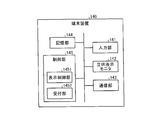
図1に示すように、第1の実施形態に係る画像処理システム1は、医用画像診断装置110と、画像保管装置120と、ワークステーション130と、端末装置140とを有する。図1に例示する各装置は、例えば、病院内に設置された院内LAN(Local Area Network)2により、直接的、又は間接的に相互に通信可能な状態となっている。例えば、画像処理システム1にPACS(Picture Archiving and Communication System)が導入されている場合、各装置は、DICOM(Digital Imaging and Communications in Medicine)規格に則って、医用画像等を相互に送受信する。
As shown in FIG. 1, the image processing system 1 according to the first embodiment includes a medical image diagnostic apparatus 110, an image storage apparatus 120, a workstation 130, and a terminal apparatus 140. Each device illustrated in FIG. 1 is in a state where it can communicate with each other directly or indirectly by, for example, an in-hospital LAN (Local Area Network) 2 installed in a hospital. For example, when PACS (Picture Archiving and Communication System) is introduced into the image processing system 1, each apparatus transmits and receives medical images and the like according to the DICOM (Digital Imaging and Communications in Medicine) standard.
かかる画像処理システム1は、医用画像診断装置110により生成された3次元の医用画像データであるボリュームデータから視差画像群を生成し、この視差画像群を立体視可能なモニタに表示することで、病院内に勤務する医師や検査技師等の観察者に対して、かかる観察者が立体的に視認可能な画像である立体画像を提供する。具体的には、第1の実施形態において、ワークステーション130は、ボリュームデータに対して種々の画像処理を行い、視差画像群を生成する。また、ワークステーション130及び端末装置140は、立体視可能なモニタを有し、ワークステーション130にて生成された視差画像群をモニタに表示することで立体画像を利用者に表示する。また、画像保管装置120は、医用画像診断装置110にて生成されたボリュームデータや、ワークステーション130にて生成された視差画像群を保管する。例えば、ワークステーション130や端末装置140は、画像保管装置120からボリュームデータや視差画像群を取得し、取得したボリュームデータや視差画像群に対して任意の画像処理を実行したり、視差画像群をモニタに表示したりする。以下、各装置を順に説明する。
The image processing system 1 generates a parallax image group from volume data that is three-dimensional medical image data generated by the medical image diagnostic apparatus 110, and displays the parallax image group on a stereoscopically viewable monitor. A stereoscopic image, which is an image that can be visually recognized by the observer, is provided to an observer such as a doctor or a laboratory technician working in the hospital. Specifically, in the first embodiment, the workstation 130 performs various image processes on the volume data to generate a parallax image group. In addition, the workstation 130 and the terminal device 140 have a stereoscopically visible monitor, and display a stereoscopic image to the user by displaying a parallax image group generated by the workstation 130 on the monitor. Further, the image storage device 120 stores the volume data generated by the medical image diagnostic device 110 and the parallax image group generated by the workstation 130. For example, the workstation 130 or the terminal device 140 acquires volume data or a parallax image group from the image storage device 120, executes arbitrary image processing on the acquired volume data or parallax image group, or selects a parallax image group. Or display on a monitor. Hereinafter, each device will be described in order.
医用画像診断装置110は、X線診断装置、X線CT(Computed Tomography)装置、MRI(Magnetic Resonance Imaging)装置、超音波診断装置、SPECT(Single Photon Emission Computed Tomography)装置、PET(Positron Emission computed Tomography)装置、SPECT装置とX線CT装置とが一体化されたSPECT-CT装置、PET装置とX線CT装置とが一体化されたPET-CT装置、又はこれらの装置群等である。また、第1の実施形態に係る医用画像診断装置110は、3次元の医用画像データ(ボリュームデータ)を生成可能である。
The medical image diagnostic apparatus 110 includes an X-ray diagnostic apparatus, an X-ray CT (Computed Tomography) apparatus, an MRI (Magnetic Resonance Imaging) apparatus, an ultrasonic diagnostic apparatus, a SPECT (Single Photon Emission Computed Tomography) apparatus, and a PET (Positron Emission computed Tomography). ) Apparatus, a SPECT-CT apparatus in which a SPECT apparatus and an X-ray CT apparatus are integrated, a PET-CT apparatus in which a PET apparatus and an X-ray CT apparatus are integrated, or a group of these apparatuses. Further, the medical image diagnostic apparatus 110 according to the first embodiment can generate three-dimensional medical image data (volume data).
具体的には、第1の実施形態に係る医用画像診断装置110は、被検体を撮影することによりボリュームデータを生成する。例えば、医用画像診断装置110は、被検体を撮影することにより投影データやMR信号等のデータを収集し、収集したデータから、被検体の体軸方向に沿った複数のアキシャル面の医用画像データを再構成することで、ボリュームデータを生成する。例えば、医用画像診断装置110は、500枚のアキシャル面の医用画像データを再構成する場合、この500枚のアキシャル面の医用画像データ群が、ボリュームデータとなる。なお、医用画像診断装置110により撮影された被検体の投影データやMR信号等自体をボリュームデータとしても良い。
Specifically, the medical image diagnostic apparatus 110 according to the first embodiment generates volume data by imaging a subject. For example, the medical image diagnostic apparatus 110 collects data such as projection data and MR signals by imaging the subject, and medical image data of a plurality of axial surfaces along the body axis direction of the subject from the collected data. By reconfiguring, volume data is generated. For example, when the medical image diagnostic apparatus 110 reconstructs 500 pieces of medical image data on the axial plane, the 500 pieces of medical image data groups on the axial plane become volume data. In addition, the projection data of the subject imaged by the medical image diagnostic apparatus 110, the MR signal, or the like may be used as the volume data.
また、第1の実施形態に係る医用画像診断装置110は、生成したボリュームデータを画像保管装置120に送信する。なお、医用画像診断装置110は、ボリュームデータを画像保管装置120に送信する際に、付帯情報として、例えば、患者を識別する患者ID、検査を識別する検査ID、医用画像診断装置110を識別する装置ID、医用画像診断装置110による1回の撮影を識別するシリーズID等を送信する。
Further, the medical image diagnostic apparatus 110 according to the first embodiment transmits the generated volume data to the image storage apparatus 120. The medical image diagnostic apparatus 110 identifies, for example, a patient ID for identifying a patient, an examination ID for identifying an examination, and the medical image diagnostic apparatus 110 as supplementary information when transmitting volume data to the image storage apparatus 120. A device ID, a series ID for identifying one shot by the medical image diagnostic device 110, and the like are transmitted.
画像保管装置120は、医用画像を保管するデータベースである。具体的には、第1の実施形態に係る画像保管装置120は、医用画像診断装置110からボリュームデータを受信し、受信したボリュームデータを所定の記憶部に保管する。また、第1の実施形態においては、ワークステーション130が、ボリュームデータから視差画像群を生成し、生成した視差画像群を画像保管装置120に送信する。このため、画像保管装置120は、ワークステーション130から送信された視差画像群を所定の記憶部に保管する。なお、本実施形態は、大容量の画像を保管可能なワークステーション130を用いることで、図1に例示するワークステーション130と画像保管装置120とが統合される場合であってもよい。すなわち、本実施形態は、ワークステーション130そのものにボリュームデータもしくは視差画像群を記憶させる場合であってもよい。
The image storage device 120 is a database that stores medical images. Specifically, the image storage device 120 according to the first embodiment receives volume data from the medical image diagnostic device 110 and stores the received volume data in a predetermined storage unit. In the first embodiment, the workstation 130 generates a parallax image group from the volume data, and transmits the generated parallax image group to the image storage device 120. For this reason, the image storage device 120 stores the parallax image group transmitted from the workstation 130 in a predetermined storage unit. In the present embodiment, the workstation 130 illustrated in FIG. 1 and the image storage device 120 may be integrated by using the workstation 130 that can store a large-capacity image. That is, this embodiment may be a case where volume data or a parallax image group is stored in the workstation 130 itself.
なお、第1の実施形態において、画像保管装置120に保管されたボリュームデータや視差画像群は、患者ID、検査ID、装置ID、シリーズID等と対応付けて保管される。このため、ワークステーション130や端末装置140は、患者ID、検査ID、装置ID、シリーズID等を用いた検索を行うことで、必要なボリュームデータや視差画像群を画像保管装置120から取得する。
In the first embodiment, the volume data and the parallax image group stored in the image storage device 120 are stored in association with the patient ID, examination ID, device ID, series ID, and the like. For this reason, the workstation 130 and the terminal device 140 acquire necessary volume data and a parallax image group from the image storage device 120 by performing a search using a patient ID, an examination ID, a device ID, a series ID, and the like.
ワークステーション130は、医用画像に対して画像処理を行う画像処理装置である。具体的には、第1の実施形態に係るワークステーション130は、画像保管装置120から取得したボリュームデータに対して種々のレンダリング処理を行うことで、視差画像群を生成する。
The workstation 130 is an image processing apparatus that performs image processing on medical images. Specifically, the workstation 130 according to the first embodiment generates a parallax image group by performing various rendering processes on the volume data acquired from the image storage device 120.
また、第1の実施形態に係るワークステーション130は、表示部として、立体画像を表示可能なモニタ(立体表示モニタ、立体画像表示装置とも称する)を有する。ワークステーション130は、視差画像群を生成し、生成した視差画像群を立体表示モニタに表示する。この結果、ワークステーション130の操作者は、立体表示モニタに表示された立体視可能な立体画像を確認しながら、視差画像群を生成するための操作を行うことができる。
Also, the workstation 130 according to the first embodiment has a monitor (also referred to as a stereoscopic display monitor or a stereoscopic image display device) capable of displaying a stereoscopic image as a display unit. The workstation 130 generates a parallax image group and displays the generated parallax image group on the stereoscopic display monitor. As a result, the operator of the workstation 130 can perform an operation for generating a parallax image group while confirming the stereoscopically viewable stereoscopic image displayed on the stereoscopic display monitor.
また、ワークステーション130は、生成した視差画像群を画像保管装置120や端末装置140に送信する。なお、ワークステーション130は、画像保管装置120や端末装置140に視差画像群を送信する際に、付帯情報として、例えば、患者ID、検査ID、装置ID、シリーズID等を送信する。視差画像群を画像保管装置120に送信する際に送信される付帯情報としては、視差画像群に関する付帯情報も挙げられる。視差画像群に関する付帯情報としては、視差画像の枚数(例えば、「9」)や、視差画像の解像度(例えば、「466×350画素」)や、かかる視差画像群の生成元となったボリュームデータによって表される3次元仮想空間に関する情報(ボリューム空間情報)等がある。
Further, the workstation 130 transmits the generated parallax image group to the image storage device 120 and the terminal device 140. In addition, when transmitting the parallax image group to the image storage device 120 or the terminal device 140, the workstation 130 transmits, for example, a patient ID, an examination ID, a device ID, a series ID, and the like as supplementary information. The incidental information transmitted when transmitting the parallax image group to the image storage device 120 includes incidental information regarding the parallax image group. The incidental information regarding the parallax image group includes the number of parallax images (for example, “9”), the resolution of the parallax images (for example, “466 × 350 pixels”), and the volume data that is the generation source of the parallax image group. There is information on the three-dimensional virtual space represented by (volume space information).
端末装置140は、病院内に勤務する医師や検査技師に医用画像を閲覧させるための装置である。例えば、端末装置140は、病院内に勤務する医師や検査技師により操作されるPC(Personal Computer)やタブレット式PC、PDA(Personal Digital Assistant)、携帯電話等である。具体的には、第1の実施形態に係る端末装置140は、表示部として立体表示モニタを有する。また、端末装置140は、画像保管装置120から視差画像群を取得し、取得した視差画像群を立体表示モニタに表示する。この結果、観察者である医師や検査技師は、立体視可能な医用画像を閲覧することができる。なお、端末装置140は、外部装置としての立体表示モニタと接続された任意の情報処理端末であってもよい。
The terminal device 140 is a device for allowing a doctor or laboratory technician working in a hospital to view a medical image. For example, the terminal device 140 is a PC (Personal Computer), a tablet PC, a PDA (Personal Digital Assistant), a mobile phone, or the like operated by a doctor or laboratory technician working in a hospital. Specifically, the terminal device 140 according to the first embodiment includes a stereoscopic display monitor as a display unit. In addition, the terminal device 140 acquires a parallax image group from the image storage device 120 and displays the acquired parallax image group on the stereoscopic display monitor. As a result, a doctor or laboratory technician who is an observer can view a medical image that can be viewed stereoscopically. Note that the terminal device 140 may be any information processing terminal connected to a stereoscopic display monitor as an external device.
ここで、ワークステーション130や端末装置140が有する立体表示モニタについて説明する。現在最も普及している一般的な汎用モニタは、2次元画像を2次元で表示するものであり、2次元画像を立体表示することができない。仮に、観察者が汎用モニタにて立体視を要望する場合、汎用モニタに対して画像を出力する装置は、平行法や交差法により観察者が立体視可能な2視差画像を並列表示させる必要がある。又は、汎用モニタに対して画像を出力する装置は、例えば、左目用の部分に赤色のセロハンが取り付けられ、右目用の部分に青色のセロハンが取り付けられたメガネを用いて余色法により観察者が立体視可能な画像を表示する必要がある。
Here, the stereoscopic display monitor included in the workstation 130 and the terminal device 140 will be described. A general-purpose monitor that is most popular at present displays a two-dimensional image in two dimensions, and cannot display a two-dimensional image in three dimensions. If an observer requests stereoscopic viewing on a general-purpose monitor, an apparatus that outputs an image to the general-purpose monitor needs to display two parallax images that can be viewed stereoscopically by the observer in parallel by the parallel method or the intersection method. is there. Alternatively, an apparatus that outputs an image to a general-purpose monitor, for example, uses an after-color method with an eyeglass that has a red cellophane attached to the left eye portion and a blue cellophane attached to the right eye portion. It is necessary to display a stereoscopically viewable image.
一方、立体表示モニタとしては、立体視用メガネ等の専用機器を用いることで、2視差画像(両眼視差画像とも称する)を立体視可能とするものがある。
On the other hand, as a stereoscopic display monitor, there is a stereoscopic display monitor capable of stereoscopically viewing a two-parallax image (also referred to as a binocular parallax image) by using dedicated equipment such as stereoscopic glasses.
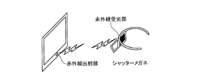
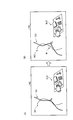
図2A及び図2Bは、2視差画像により立体表示を行う立体表示モニタの一例を説明するための図である。図2A及び図2Bに示す一例は、シャッター方式により立体表示を行う立体表示モニタであり、モニタを観察する観察者が装着する立体視用メガネとしてシャッターメガネが用いられる。かかる立体表示モニタは、モニタにて2視差画像を交互に出射する。例えば、図2Aに示すモニタは、左目用の画像と右目用の画像を、120Hzにて交互に出射する。ここで、モニタには、図2Aに示すように、赤外線出射部が設置され、赤外線出射部は、画像が切り替わるタイミングに合わせて赤外線の出射を制御する。
2A and 2B are diagrams for explaining an example of a stereoscopic display monitor that performs stereoscopic display using two parallax images. An example shown in FIGS. 2A and 2B is a stereoscopic display monitor that performs stereoscopic display by a shutter method, and shutter glasses are used as stereoscopic glasses worn by an observer who observes the monitor. Such a stereoscopic display monitor emits two parallax images alternately on the monitor. For example, the monitor shown in FIG. 2A alternately emits a left-eye image and a right-eye image at 120 Hz. Here, as shown in FIG. 2A, the monitor is provided with an infrared emitting unit, and the infrared emitting unit controls the emission of infrared rays in accordance with the timing at which the image is switched.
また、赤外線出射部から出射された赤外線は、図2Aに示すシャッターメガネの赤外線受光部により受光される。シャッターメガネの左右それぞれの枠には、シャッターが取り付けられており、シャッターメガネは、赤外線受光部が赤外線を受光したタイミングに合わせて左右のシャッターそれぞれの透過状態及び遮光状態を交互に切り替える。以下、シャッターにおける透過状態及び遮光状態の切り替え処理について説明する。
Further, the infrared light emitted from the infrared light emitting unit is received by the infrared light receiving unit of the shutter glasses shown in FIG. 2A. A shutter is attached to each of the left and right frames of the shutter glasses, and the shutter glasses alternately switch the transmission state and the light shielding state of the left and right shutters according to the timing when the infrared light receiving unit receives the infrared rays. Hereinafter, the switching process between the transmission state and the light shielding state in the shutter will be described.
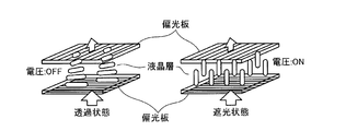
各シャッターは、図2Bに示すように、入射側の偏光板と出射側の偏光板とを有し、更に、入射側の偏光板と出射側の偏光板との間に液晶層を有する。また、入射側の偏光板と出射側の偏光板とは、図2Bに示すように、互いに直交している。ここで、図2Bに示すように、電圧が印加されていない「OFF」の状態では、入射側の偏光板を通った光は、液晶層の作用により90度回転し、出射側の偏光板を透過する。すなわち、電圧が印加されていないシャッターは、透過状態となる。
As shown in FIG. 2B, each shutter has an incident-side polarizing plate and an output-side polarizing plate, and further has a liquid crystal layer between the incident-side polarizing plate and the output-side polarizing plate. In addition, as shown in FIG. 2B, the incident-side polarizing plate and the outgoing-side polarizing plate are orthogonal to each other. Here, as shown in FIG. 2B, in an “OFF” state in which no voltage is applied, the light passing through the incident-side polarizing plate is rotated 90 degrees by the action of the liquid crystal layer, and the outgoing-side polarizing plate is To Penetrate. That is, a shutter to which no voltage is applied is in a transmissive state.
一方、図2Bに示すように、電圧が印加された「ON」の状態では、液晶層の液晶分子による偏光回転作用が消失するため、入射側の偏光板を通った光は、出射側の偏光板で遮られてしまう。すなわち、電圧が印加されたシャッターは、遮光状態となる。
On the other hand, as shown in FIG. 2B, in the “ON” state in which a voltage is applied, the polarization rotation action caused by the liquid crystal molecules in the liquid crystal layer disappears. It will be blocked by a board. That is, the shutter to which the voltage is applied is in a light shielding state.
そこで、例えば、赤外線出射部は、モニタ上に左目用の画像が表示されている期間、赤外線を出射する。そして、赤外線受光部は、赤外線を受光している期間、左目のシャッターに電圧を印加せず、右目のシャッターに電圧を印加させる。これにより、図2Aに示すように、右目のシャッターが遮光状態となり、左目のシャッターが透過状態となるため、観察者の左目に左目用の画像が入射する。一方、赤外線出射部は、モニタ上に右目用の画像が表示されている期間、赤外線の出射を停止する。そして、赤外線受光部は、赤外線が受光されない期間、右目のシャッターに電圧を印加せず、左目のシャッターに電圧を印加させる。これにより、左目のシャッターが遮光状態となり、右目のシャッターが透過状態であるため、観察者の右目に右目用の画像が入射する。このように、図2A及び図2Bに示す立体表示モニタは、モニタに表示される画像とシャッターの状態を連動させて切り替えることで、観察者が立体視可能な画像を表示させる。なお、2視差画像を立体視可能な立体表示モニタとしては、上記のシャッター方式以外にも、偏光メガネ方式を採用したモニタも知られている。
Therefore, for example, the infrared emitting unit emits infrared rays while the image for the left eye is displayed on the monitor. The infrared light receiving unit applies a voltage to the right-eye shutter without applying a voltage to the left-eye shutter during a period of receiving the infrared light. As a result, as shown in FIG. 2A, the right-eye shutter is in a light-shielding state and the left-eye shutter is in a transmissive state, so that an image for the left eye enters the left eye of the observer. On the other hand, the infrared ray emitting unit stops emitting infrared rays while the right-eye image is displayed on the monitor. The infrared light receiving unit applies a voltage to the left-eye shutter without applying a voltage to the right-eye shutter during a period in which no infrared light is received. Accordingly, the left-eye shutter is in a light-shielding state and the right-eye shutter is in a transmissive state, so that an image for the right eye is incident on the right eye of the observer. As described above, the stereoscopic display monitor illustrated in FIGS. 2A and 2B displays an image that can be viewed stereoscopically by the observer by switching the image displayed on the monitor and the state of the shutter in conjunction with each other. As a stereoscopic display monitor capable of stereoscopically viewing a two-parallax image, a monitor adopting a polarized glasses method is also known in addition to the shutter method described above.
更に、近年実用化された立体表示モニタとしては、レンチキュラーレンズ等の光線制御子を用いることで、例えば、9視差画像等の多視差画像を観察者が裸眼にて立体視可能とするものがある。かかる立体表示モニタは、両眼視差による立体視を可能とし、更に、観察者の視点移動に合わせて観察される映像も変化する運動視差による立体視も可能とする。
Furthermore, as a stereoscopic display monitor that has been put into practical use in recent years, there is a stereoscopic display monitor that allows a viewer to stereoscopically view a multi-parallax image such as a 9-parallax image with the naked eye by using a light controller such as a lenticular lens. . Such a stereoscopic display monitor enables stereoscopic viewing based on binocular parallax, and also enables stereoscopic viewing based on motion parallax that also changes the image observed in accordance with the viewpoint movement of the observer.
図3は、9視差画像により立体表示を行う立体表示モニタの一例を説明するための図である。図3に示す立体表示モニタには、液晶パネル等の平面状の表示面200の前面に、光線制御子が配置される。例えば、図3に示す立体表示モニタには、光線制御子として、光学開口が垂直方向に延びる垂直レンチキュラーシート201が表示面200の前面に貼り付けられている。なお、図3に示す一例では、垂直レンチキュラーシート201の凸部が前面となるように貼り付けられているが、垂直レンチキュラーシート201の凸部が表示面200に対向するように貼り付けられる場合であってもよい。
FIG. 3 is a diagram for explaining an example of a stereoscopic display monitor that performs stereoscopic display with nine parallax images. In the stereoscopic display monitor shown in FIG. 3, a light beam controller is arranged on the front surface of a flat display surface 200 such as a liquid crystal panel. For example, in the stereoscopic display monitor shown in FIG. 3, a vertical lenticular sheet 201 whose optical aperture extends in the vertical direction is attached to the front surface of the display surface 200 as a light beam controller. In the example shown in FIG. 3, the vertical lenticular sheet 201 is pasted so that the convex portion of the vertical lenticular sheet 201 becomes the front surface, but the convex portion of the vertical lenticular sheet 201 is pasted so as to face the display surface 200. There may be.
表示面200には、図3に示すように、縦横比が3:1であり、縦方向にサブ画素である赤(R)、緑(G)、青(B)の3つが配置された画素202がマトリクス状に配置される。図3に示す立体表示モニタは、9つの画像により構成される9視差画像を、所定フォーマット(例えば格子状)に配置した中間画像に変換したうえで、表示面200に出力する。すなわち、図3に示す立体表示モニタは、9視差画像にて同一位置にある9つの画素それぞれを、9列の画素202に割り振って出力させる。9列の画素202は、視点位置の異なる9つの画像を同時に表示する単位画素群203となる。
As shown in FIG. 3, the display surface 200 has an aspect ratio of 3: 1 and pixels in which three sub-pixels, red (R), green (G), and blue (B), are arranged in the vertical direction. 202 are arranged in a matrix. The stereoscopic display monitor shown in FIG. 3 converts a nine-parallax image composed of nine images into an intermediate image arranged in a predetermined format (for example, a lattice shape), and then outputs it to the display surface 200. That is, the stereoscopic display monitor shown in FIG. 3 assigns and outputs nine pixels at the same position in nine parallax images to nine columns of pixels 202. The nine columns of pixels 202 constitute a unit pixel group 203 that simultaneously displays nine images with different viewpoint positions.
表示面200において単位画素群203として同時に出力された9視差画像は、例えば、LED(Light Emitting Diode)バックライトにより平行光として放射され、更に、垂直レンチキュラーシート201により、多方向に放射される。9視差画像の各画素の光が多方向に放射されることにより、観察者の右目及び左目に入射する光は、観察者の位置(視点の位置)に連動して変化する。すなわち、観察者の見る角度により、右目に入射する視差画像と左目に入射する視差画像とは、視差角が異なる。これにより、観察者は、例えば、図3に示す9つの位置それぞれにおいて、撮影対象を立体的に視認できる。また、観察者は、例えば、図3に示す「5」の位置において、撮影対象に対して正対した状態で立体的に視認できるとともに、図3に示す「5」以外それぞれの位置において、撮影対象の向きを変化させた状態で立体的に視認できる。なお、図3に示す立体表示モニタは、あくまでも一例である。9視差画像を表示する立体表示モニタは、図3に示すように、「RRR・・・、GGG・・・、BBB・・・」の横ストライプ液晶である場合であってもよいし、「RGBRGB・・・」の縦ストライプ液晶である場合であってもよい。また、図3に示す立体表示モニタは、図3に示すように、レンチキュラーシートが垂直となる縦レンズ方式である場合であってもよいし、レンチキュラーシートが斜めとなる斜めレンズ方式である場合であってもよい。
The nine-parallax images simultaneously output as the unit pixel group 203 on the display surface 200 are emitted as parallel light by, for example, an LED (Light Emitting Diode) backlight, and further emitted in multiple directions by the vertical lenticular sheet 201. As the light of each pixel of the nine-parallax image is emitted in multiple directions, the light incident on the right eye and the left eye of the observer changes in conjunction with the position of the observer (viewpoint position). That is, the parallax angle between the parallax image incident on the right eye and the parallax image incident on the left eye differs depending on the viewing angle of the observer. Thereby, the observer can visually recognize the photographing object in three dimensions at each of the nine positions shown in FIG. 3, for example. In addition, for example, the observer can view the image three-dimensionally in a state of facing the object to be imaged at the position “5” shown in FIG. 3, and at each position other than “5” shown in FIG. It can be visually recognized in a three-dimensional manner with the direction of the object changed. Note that the stereoscopic display monitor shown in FIG. 3 is merely an example. As shown in FIG. 3, the stereoscopic display monitor that displays the nine-parallax image may be a horizontal stripe liquid crystal of “RRR..., GGG..., BBB. .. ”” May be used. Further, the stereoscopic display monitor shown in FIG. 3 may be a vertical lens system in which the lenticular sheet is vertical as shown in FIG. 3 or a diagonal lens system in which the lenticular sheet is oblique. There may be.
ここまで、第1の実施形態に係る画像処理システム1の構成例について簡単に説明した。なお、上述した画像処理システム1は、PACSが導入されている場合にその適用が限られるものではない。例えば、画像処理システム1は、医用画像が添付された電子カルテを管理する電子カルテシステムが導入されている場合にも、同様に適用される。この場合、画像保管装置120は、電子カルテを保管するデータベースである。また、例えば、画像処理システム1は、HIS(Hospital Information System)、RIS(Radiology Information System)が導入されている場合にも、同様に適用される。また、画像処理システム1は、上述した構成例に限られるものではない。各装置が有する機能やその分担は、運用の形態に応じて適宜変更されてよい。
So far, the configuration example of the image processing system 1 according to the first embodiment has been briefly described. Note that the application of the image processing system 1 described above is not limited when PACS is introduced. For example, the image processing system 1 is similarly applied when an electronic medical chart system that manages an electronic medical chart to which a medical image is attached is introduced. In this case, the image storage device 120 is a database that stores electronic medical records. Further, for example, the image processing system 1 is similarly applied when a HIS (Hospital Information System) and a RIS (Radiology Information System) are introduced. The image processing system 1 is not limited to the configuration example described above. The functions and sharing of each device may be appropriately changed according to the operation mode.
次に、第1の実施形態に係るワークステーションの構成例について図4を用いて説明する。図4は、第1の実施形態に係るワークステーションの構成例を説明するための図である。なお、以下において、「視差画像群」とは、ボリュームデータに対してボリュームレンダリング処理を行うことで生成された立体視用の画像群のことである。また、「視差画像」とは、「視差画像群」を構成する個々の画像のことである。すなわち、「視差画像群」は、視点位置が異なる複数の「視差画像」から構成される。
Next, a configuration example of the workstation according to the first embodiment will be described with reference to FIG. FIG. 4 is a diagram for explaining a configuration example of the workstation according to the first embodiment. In the following description, the “parallax image group” refers to a group of stereoscopic images generated by performing volume rendering processing on volume data. Further, the “parallax image” is an individual image constituting the “parallax image group”. That is, the “parallax image group” includes a plurality of “parallax images” having different viewpoint positions.
第1の実施形態に係るワークステーション130は、画像処理等に適した高性能なコンピュータであり、図4に示すように、入力部131と、表示部132と、通信部133と、記憶部134と、制御部135と、レンダリング処理部136とを有する。なお、以下では、ワークステーション130が画像処理等に適した高性能なコンピュータである場合を用いて説明するが、これに限定されるものではなく、任意の情報処理装置であってよい。例えば、任意のパーソナルコンピュータであってもよい。
The workstation 130 according to the first embodiment is a high-performance computer suitable for image processing and the like, and as illustrated in FIG. 4, an input unit 131, a display unit 132, a communication unit 133, and a storage unit 134. And a control unit 135 and a rendering processing unit 136. In the following description, the workstation 130 is a high-performance computer suitable for image processing or the like. However, the present invention is not limited to this, and may be any information processing apparatus. For example, any personal computer may be used.
入力部131は、マウス、キーボード、トラックボール等であり、ワークステーション130に対する各種操作の入力を操作者から受け付ける。具体的には、第1の実施形態に係る入力部131は、レンダリング処理の対象となるボリュームデータを画像保管装置120から取得するための情報の入力を受け付ける。例えば、入力部131は、患者ID、検査ID、装置ID、シリーズID等の入力を受け付ける。また、第1の実施形態に係る入力部131は、レンダリング処理に関する条件(以下、レンダリング条件)の入力を受け付ける。
The input unit 131 is a mouse, a keyboard, a trackball, or the like, and receives input of various operations on the workstation 130 from the operator. Specifically, the input unit 131 according to the first embodiment receives input of information for acquiring volume data to be subjected to rendering processing from the image storage device 120. For example, the input unit 131 receives input of a patient ID, an examination ID, a device ID, a series ID, and the like. Further, the input unit 131 according to the first embodiment receives an input of a condition regarding rendering processing (hereinafter, rendering condition).
表示部132は、立体表示モニタとしての液晶パネル等であり、各種情報を表示する。具体的には、第1の実施形態に係る表示部132は、操作者から各種操作を受け付けるためのGUI(Graphical User Interface)や、視差画像群等を表示する。通信部133は、NIC(Network Interface Card)等であり、他の装置との間で通信を行う。
The display unit 132 is a liquid crystal panel or the like as a stereoscopic display monitor, and displays various types of information. Specifically, the display unit 132 according to the first embodiment displays a GUI (Graphical User Interface) for receiving various operations from the operator, a parallax image group, and the like. The communication unit 133 is a NIC (Network Interface Card) or the like, and communicates with other devices.
記憶部134は、ハードディスク、半導体メモリ素子等であり、各種情報を記憶する。具体的には、第1の実施形態に係る記憶部134は、通信部133を介して画像保管装置120から取得したボリュームデータを記憶する。また、第1の実施形態に係る記憶部134は、レンダリング処理中のボリュームデータや、レンダリング処理により生成された視差画像群等を記憶する。
The storage unit 134 is a hard disk, a semiconductor memory element, or the like, and stores various information. Specifically, the storage unit 134 according to the first embodiment stores volume data acquired from the image storage device 120 via the communication unit 133. In addition, the storage unit 134 according to the first embodiment stores volume data during rendering processing, a group of parallax images generated by the rendering processing, and the like.
制御部135は、CPU(Central Processing Unit)、MPU(Micro Processing Unit)やGPU(Graphics Processing Unit)等の電子回路、ASIC(Application Specific Integrated Circuit)やFPGA(Field Programmable Gate Array)等の集積回路であり、ワークステーション130の全体制御を行う。
The control unit 135 is an electronic circuit such as a CPU (Central Processing Unit), MPU (Micro Processing Unit) or GPU (Graphics Processing Unit), or an integrated circuit such as an ASIC (Application Specific Integrated Circuit) or FPGA (Field Programmable Gate Array). Yes, the entire control of the workstation 130 is performed.
例えば、第1の実施形態に係る制御部135は、表示部132に対するGUIの表示や視差画像群の表示を制御する。また、例えば、制御部135は、画像保管装置120との間で通信部133を介して行われるボリュームデータや視差画像群の送受信を制御する。また、例えば、制御部135は、レンダリング処理部136によるレンダリング処理を制御する。また、例えば、制御部135は、ボリュームデータの記憶部134からの読み込みや、視差画像群の記憶部134への格納を制御する。
For example, the control unit 135 according to the first embodiment controls the display of the GUI and the display of the parallax image group on the display unit 132. For example, the control unit 135 controls transmission / reception of volume data and a parallax image group performed with the image storage device 120 via the communication unit 133. For example, the control unit 135 controls the rendering process performed by the rendering processing unit 136. For example, the control unit 135 controls reading of volume data from the storage unit 134 and storage of the parallax image group in the storage unit 134.
レンダリング処理部136は、制御部135による制御の下、画像保管装置120から取得したボリュームデータに対して種々のレンダリング処理を行い、視差画像群を生成する。具体的には、第1の実施形態に係るレンダリング処理部136は、記憶部134からボリュームデータを読み込み、このボリュームデータに対して、まず前処理を行う。次に、レンダリング処理部136は、前処理後のボリュームデータに対してボリュームレンダリング処理を行い、視差画像群を生成する。続いて、レンダリング処理部136は、各種情報(目盛り、患者名、検査項目等)が描出された2次元画像を生成し、これを視差画像群それぞれに対して重畳することで、出力用の2次元画像を生成する。そして、レンダリング処理部136は、生成した視差画像群や出力用の2次元画像を記憶部134に格納する。なお、第1の実施形態において、レンダリング処理とは、ボリュームデータに対して行う画像処理全体のことであり、ボリュームレンダリング処理とは、レンダリング処理の内、3次元の情報を反映した2次元画像を生成する処理のことである。レンダリング処理により生成される医用画像とは、例えば、視差画像が該当する。
The rendering processing unit 136 performs various rendering processes on the volume data acquired from the image storage device 120 under the control of the control unit 135, and generates a parallax image group. Specifically, the rendering processing unit 136 according to the first embodiment reads volume data from the storage unit 134 and first performs preprocessing on the volume data. Next, the rendering processing unit 136 performs a volume rendering process on the pre-processed volume data to generate a parallax image group. Subsequently, the rendering processing unit 136 generates a two-dimensional image in which various kinds of information (scale, patient name, examination item, etc.) are drawn, and superimposes it on each of the parallax image groups, thereby outputting 2 for output. Generate a dimensional image. Then, the rendering processing unit 136 stores the generated parallax image group and the output two-dimensional image in the storage unit 134. In the first embodiment, rendering processing refers to the entire image processing performed on volume data. Volume rendering processing refers to a two-dimensional image reflecting three-dimensional information in the rendering processing. It is a process to generate. For example, a parallax image corresponds to the medical image generated by the rendering process.
図5は、図4に示すレンダリング処理部の構成例を説明するための図である。図5に示すように、レンダリング処理部136は、前処理部1361と、3次元画像処理部1362と、2次元画像処理部1363とを有する。前処理部1361が、ボリュームデータに対する前処理を行い、3次元画像処理部1362が、前処理後のボリュームデータから視差画像群を生成し、2次元画像処理部1363が、視差画像群に各種情報が重畳された出力用の2次元画像を生成する。以下、各部を順に説明する。
FIG. 5 is a diagram for explaining a configuration example of the rendering processing unit shown in FIG. As illustrated in FIG. 5, the rendering processing unit 136 includes a preprocessing unit 1361, a 3D image processing unit 1362, and a 2D image processing unit 1363. The preprocessing unit 1361 performs preprocessing on the volume data, the 3D image processing unit 1362 generates a parallax image group from the preprocessed volume data, and the 2D image processing unit 1363 stores various information on the parallax image group. A two-dimensional image for output on which is superimposed is generated. Hereinafter, each part is demonstrated in order.
前処理部1361は、ボリュームデータに対してレンダリング処理を行う際に、種々の前処理を行う処理部であり、画像補正処理部1361aと、3次元物体フュージョン部1361eと、3次元物体表示領域設定部1361fとを有する。
The preprocessing unit 1361 is a processing unit that performs various types of preprocessing when rendering processing is performed on volume data, and includes an image correction processing unit 1361a, a three-dimensional object fusion unit 1361e, and a three-dimensional object display area setting. Part 1361f.
画像補正処理部1361aは、2種類のボリュームデータを1つのボリュームデータとして処理する際に画像補正処理を行う処理部であり、図5に示すように、歪み補正処理部1361b、体動補正処理部1361c及び画像間位置合わせ処理部1361dを有する。例えば、画像補正処理部1361aは、PET-CT装置により生成されたPET画像のボリュームデータとX線CT画像のボリュームデータとを1つのボリュームデータとして処理する際に画像補正処理を行う。或いは、画像補正処理部1361aは、MRI装置により生成されたT1強調画像のボリュームデータとT2強調画像のボリュームデータとを1つのボリュームデータとして処理する際に画像補正処理を行う。
The image correction processing unit 1361a is a processing unit that performs image correction processing when processing two types of volume data as one volume data, and as illustrated in FIG. 5, a distortion correction processing unit 1361b, a body motion correction processing unit, 1361c and an inter-image registration processing unit 1361d. For example, the image correction processing unit 1361a performs image correction processing when processing volume data of a PET image generated by a PET-CT apparatus and volume data of an X-ray CT image as one volume data. Alternatively, the image correction processing unit 1361a performs image correction processing when processing the volume data of the T1-weighted image and the volume data of the T2-weighted image generated by the MRI apparatus as one volume data.
また、歪み補正処理部1361bは、個々のボリュームデータにおいて、医用画像診断装置110によるデータ収集時の収集条件に起因するデータの歪みを補正する。また、体動補正処理部1361cは、個々のボリュームデータを生成するために用いられたデータの収集時期における被検体の体動に起因する移動を補正する。また、画像間位置合わせ処理部1361dは、歪み補正処理部1361b及び体動補正処理部1361cによる補正処理が行われた2つのボリュームデータ間で、例えば、相互相関法等を用いた位置合わせ(Registration)を行う。
In addition, the distortion correction processing unit 1361b corrects the data distortion caused by the collection conditions at the time of data collection by the medical image diagnostic apparatus 110 in each volume data. Further, the body motion correction processing unit 1361c corrects the movement caused by the body motion of the subject at the time of collecting the data used for generating the individual volume data. Further, the inter-image registration processing unit 1361d performs registration (Registration) using, for example, a cross-correlation method between the two volume data subjected to the correction processing by the distortion correction processing unit 1361b and the body motion correction processing unit 1361c. )I do.
3次元物体フュージョン部1361eは、画像間位置合わせ処理部1361dにより位置合わせが行われた複数のボリュームデータをフュージョンさせる。なお、画像補正処理部1361a及び3次元物体フュージョン部1361eの処理は、単一のボリュームデータに対してレンダリング処理を行う場合、省略される。
The three-dimensional object fusion unit 1361e fuses a plurality of volume data that have been aligned by the inter-image alignment processing unit 1361d. Note that the processing of the image correction processing unit 1361a and the three-dimensional object fusion unit 1361e is omitted when rendering processing is performed on single volume data.
3次元物体表示領域設定部1361fは、操作者により指定された表示対象臓器に対応する表示領域を設定する処理部であり、セグメンテーション処理部1361gを有する。セグメンテーション処理部1361gは、操作者により指定された心臓、肺、血管等の臓器を、例えば、ボリュームデータの画素値(ボクセル値)に基づく領域拡張法により抽出する処理部である。
The three-dimensional object display area setting unit 1361f is a processing unit that sets a display area corresponding to a display target organ designated by the operator, and includes a segmentation processing unit 1361g. The segmentation processing unit 1361g is a processing unit that extracts organs such as the heart, lungs, and blood vessels designated by the operator by, for example, a region expansion method based on pixel values (voxel values) of volume data.
なお、セグメンテーション処理部1361gは、操作者により表示対象臓器が指定されなかった場合、セグメンテーション処理を行わない。また、セグメンテーション処理部1361gは、操作者により表示対象臓器が複数指定された場合、該当する複数の臓器を抽出する。また、セグメンテーション処理部1361gの処理は、レンダリング画像を参照した操作者の微調整要求により再度実行される場合もある。
Note that the segmentation processing unit 1361 g does not perform the segmentation processing when the display target organ is not designated by the operator. The segmentation processing unit 1361g extracts a plurality of corresponding organs when a plurality of display target organs are designated by the operator. Further, the processing of the segmentation processing unit 1361g may be executed again in response to an operator fine adjustment request referring to the rendered image.
3次元画像処理部1362は、前処理部1361が処理を行った前処理後のボリュームデータに対してボリュームレンダリング処理を行う。ボリュームレンダリング処理を行う処理部として、3次元画像処理部1362は、投影方法設定部1362aと、3次元幾何変換処理部1362bと、3次元物体アピアランス処理部1362fと、3次元仮想空間レンダリング部1362kとを有する。
The 3D image processing unit 1362 performs a volume rendering process on the pre-processed volume data processed by the pre-processing unit 1361. As a processing unit that performs volume rendering processing, a 3D image processing unit 1362 includes a projection method setting unit 1362a, a 3D geometric transformation processing unit 1362b, a 3D object appearance processing unit 1362f, and a 3D virtual space rendering unit 1362k. Have
投影方法設定部1362aは、視差画像群を生成するための投影方法を決定する。例えば、投影方法設定部1362aは、ボリュームレンダリング処理を平行投影法により実行するか、透視投影法により実行するかを決定する。
Projection method setting unit 1362a determines a projection method for generating a parallax image group. For example, the projection method setting unit 1362a determines whether to execute the volume rendering process by the parallel projection method or the perspective projection method.
3次元幾何変換処理部1362bは、ボリュームレンダリング処理が実行されるボリュームデータを3次元幾何学的に変換するための情報を決定する処理部であり、平行移動処理部1362c、回転処理部1362d及び拡大縮小処理部1362eを有する。平行移動処理部1362cは、ボリュームレンダリング処理を行う際の視点位置が平行移動された場合に、ボリュームデータを平行移動させる移動量を決定する処理部であり、回転処理部1362dは、ボリュームレンダリング処理を行う際の視点位置が回転移動された場合に、ボリュームデータを回転移動させる移動量を決定する処理部である。また、拡大縮小処理部1362eは、視差画像群の拡大や縮小が要求された場合に、ボリュームデータの拡大率や縮小率を決定する処理部である。
The three-dimensional geometric transformation processing unit 1362b is a processing unit that determines information for transforming volume data on which volume rendering processing is performed into a three-dimensional geometrical structure. The three-dimensional geometric transformation processing unit 1362b includes a parallel movement processing unit 1362c, a rotation processing unit 1362d, and an enlargement unit. A reduction processing unit 1362e is included. The translation processing unit 1362c is a processing unit that determines the amount of movement to translate the volume data when the viewpoint position when performing the volume rendering processing is translated, and the rotation processing unit 1362d performs the volume rendering processing. This is a processing unit that determines the amount of movement to rotate the volume data when the viewpoint position at the time of rotation is rotated. The enlargement / reduction processing unit 1362e is a processing unit that determines the enlargement rate or reduction rate of the volume data when enlargement or reduction of the parallax image group is requested.
3次元物体アピアランス処理部1362fは、3次元物体色彩処理部1362g、3次元物体不透明度処理部1362h、3次元物体材質処理部1362i及び3次元仮想空間光源処理部1362jを有する。3次元物体アピアランス処理部1362fは、これらの処理部により、例えば、操作者の要求に応じて、表示される視差画像群の表示状態を決定する処理を行う。
The 3D object appearance processing unit 1362f includes a 3D object color processing unit 1362g, a 3D object opacity processing unit 1362h, a 3D object material processing unit 1362i, and a 3D virtual space light source processing unit 1362j. The three-dimensional object appearance processing unit 1362f performs a process of determining the display state of the displayed parallax image group in response to an operator's request, for example.
3次元物体色彩処理部1362gは、ボリュームデータにてセグメンテーションされた各領域に対して着色される色彩を決定する処理部である。3次元物体不透明度処理部1362hは、ボリュームデータにてセグメンテーションされた各領域を構成する各ボクセルの不透過度(Opacity)を決定する処理部である。なお、ボリュームデータにおいて不透過度が「100%」とされた領域の後方の領域は、視差画像群において描出されないこととなる。また、ボリュームデータにおいて不透過度が「0%」とされた領域は、視差画像群において描出されないこととなる。
The three-dimensional object color processing unit 1362g is a processing unit that determines a color to be colored for each region segmented by the volume data. The three-dimensional object opacity processing unit 1362h is a processing unit that determines the opacity (Opacity) of each voxel constituting each region segmented by volume data. It should be noted that the area behind the area having the opacity of “100%” in the volume data is not drawn in the parallax image group. In addition, an area in which the opacity is “0%” in the volume data is not drawn in the parallax image group.
3次元物体材質処理部1362iは、ボリュームデータにてセグメンテーションされた各領域の材質を決定することで、この領域が描出される際の質感を調整する処理部である。3次元仮想空間光源処理部1362jは、ボリュームデータに対してボリュームレンダリング処理を行う際に、3次元仮想空間に設置する仮想光源の位置や、仮想光源の種類を決定する処理部である。仮想光源の種類としては、無限遠から平行光線を照射する光源や、視点から放射状の光線を照射する光源等が挙げられる。
The three-dimensional object material processing unit 1362i is a processing unit that determines the material of each region segmented by volume data and adjusts the texture when this region is rendered. The three-dimensional virtual space light source processing unit 1362j is a processing unit that determines the position of the virtual light source installed in the three-dimensional virtual space and the type of the virtual light source when performing volume rendering processing on the volume data. Examples of the virtual light source include a light source that emits parallel rays from infinity, a light source that emits radial rays from a viewpoint, and the like.
3次元仮想空間レンダリング部1362kは、ボリュームデータに対してボリュームレンダリング処理を行い、視差画像群を生成する。また、3次元仮想空間レンダリング部1362kは、ボリュームレンダリング処理を行う際、必要に応じて、投影方法設定部1362a、3次元幾何変換処理部1362b、3次元物体アピアランス処理部1362fにより決定された各種情報を用いる。
The 3D virtual space rendering unit 1362k performs volume rendering processing on the volume data to generate a parallax image group. The three-dimensional virtual space rendering unit 1362k performs various types of information determined by the projection method setting unit 1362a, the three-dimensional geometric transformation processing unit 1362b, and the three-dimensional object appearance processing unit 1362f as necessary when performing the volume rendering process. Is used.
ここで、3次元仮想空間レンダリング部1362kによるボリュームレンダリング処理は、レンダリング条件に従って行われることになる。例えば、レンダリング条件は、「平行投影法」又は「透視投影法」である。また、例えば、レンダリング条件は、「基準の視点位置、視差角及び視差数」である。また、例えば、レンダリング条件は、「視点位置の平行移動」、「視点位置の回転移動」、「視差画像群の拡大」、「視差画像群の縮小」である。また、例えば、レンダリング条件は、「着色される色彩」、「透過度」、「質感」、「仮想光源の位置」、「仮想光源の種類」である。このようなレンダリング条件は、入力部131を介して操作者から受け付ける場合や、初期設定される場合が考えられる。いずれの場合も、3次元仮想空間レンダリング部1362kは、制御部135からレンダリング条件を受け付け、このレンダリング条件に従って、ボリュームデータに対するボリュームレンダリング処理を行う。また、このとき、上述した投影方法設定部1362a、3次元幾何変換処理部1362b、3次元物体アピアランス処理部1362fが、このレンダリング条件に従って必要な各種情報を決定するので、3次元仮想空間レンダリング部1362kは、決定されたこれらの各種情報を用いて視差画像群を生成する。
Here, the volume rendering process by the three-dimensional virtual space rendering unit 1362k is performed according to the rendering conditions. For example, the rendering condition is “parallel projection method” or “perspective projection method”. For example, the rendering condition is “reference viewpoint position, parallax angle, and number of parallaxes”. Further, for example, the rendering conditions are “translation of viewpoint position”, “rotational movement of viewpoint position”, “enlargement of parallax image group”, and “reduction of parallax image group”. Further, for example, the rendering conditions are “color to be colored”, “transparency”, “texture”, “position of virtual light source”, and “type of virtual light source”. Such a rendering condition may be accepted from the operator via the input unit 131 or may be initially set. In any case, the three-dimensional virtual space rendering unit 1362k receives a rendering condition from the control unit 135, and performs volume rendering processing on the volume data according to the rendering condition. At this time, the projection method setting unit 1362a, the three-dimensional geometric transformation processing unit 1362b, and the three-dimensional object appearance processing unit 1362f determine various pieces of necessary information according to the rendering conditions, so the three-dimensional virtual space rendering unit 1362k. Generates a parallax image group using the determined various pieces of information.
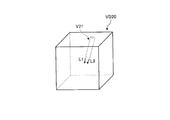
図6は、第1の実施形態に係るボリュームレンダリング処理の一例を説明するための図である。例えば、3次元仮想空間レンダリング部1362kが、図6の「9視差画像生成方式(1)」に示すように、レンダリング条件として、平行投影法を受け付け、更に、基準の視点位置(5)と視差角「1度」とを受け付けたとする。かかる場合、3次元仮想空間レンダリング部1362kは、視差角が「1度」おきとなるように、視点の位置を(1)~(9)に平行移動して、平行投影法により視差角(視線方向間の角度)が1度ずつ異なる9つの視差画像を生成する。なお、平行投影法を行う場合、3次元仮想空間レンダリング部1362kは、視線方向に沿って無限遠から平行光線を照射する光源を設定する。
FIG. 6 is a diagram for explaining an example of the volume rendering process according to the first embodiment. For example, as shown in “9 parallax image generation method (1)” in FIG. 6, the three-dimensional virtual space rendering unit 1362k accepts the parallel projection method as a rendering condition, and further, the reference viewpoint position (5) and the parallax. Assume that the angle “1 degree” is received. In such a case, the three-dimensional virtual space rendering unit 1362k translates the position of the viewpoint from (1) to (9) so that the parallax angle is every “1 degree”, and performs the parallax angle (line of sight) by the parallel projection method. Nine parallax images with different degrees between directions are generated. When performing the parallel projection method, the three-dimensional virtual space rendering unit 1362k sets a light source that emits parallel rays from infinity along the line-of-sight direction.
或いは、3次元仮想空間レンダリング部1362kが、図6の「9視差画像生成方式(2)」に示すように、レンダリング条件として、透視投影法を受け付け、更に、基準の視点位置(5)と視差角「1度」とを受け付けたとする。かかる場合、3次元仮想空間レンダリング部1362kは、ボリュームデータの中心(重心)を中心に視差角が「1度」おきとなるように、視点の位置を(1)~(9)に回転移動して、透視投影法により視差角が1度ずつ異なる9つの視差画像を生成する。なお、透視投影法を行う場合、3次元仮想空間レンダリング部1362kは、視線方向を中心に光を3次元的に放射状に照射する点光源や面光源を各視点にて設定する。また、透視投影法を行う場合、レンダリング条件によっては、視点(1)~(9)は、平行移動される場合であってもよい。
Alternatively, as shown in “9-parallax image generation method (2)” in FIG. 6, the three-dimensional virtual space rendering unit 1362k accepts a perspective projection method as a rendering condition, and further, the reference viewpoint position (5) and the parallax Assume that the angle “1 degree” is received. In such a case, the three-dimensional virtual space rendering unit 1362k rotates and moves the viewpoint position from (1) to (9) so that the parallax angle is “1 degree” around the center (center of gravity) of the volume data. Thus, nine parallax images having different parallax angles by 1 degree are generated by the perspective projection method. When performing the perspective projection method, the three-dimensional virtual space rendering unit 1362k sets a point light source or a surface light source that radiates light three-dimensionally radially around the viewing direction at each viewpoint. When the perspective projection method is performed, the viewpoints (1) to (9) may be moved in parallel depending on rendering conditions.
なお、3次元仮想空間レンダリング部1362kは、表示されるボリュームレンダリング画像の縦方向に対しては、視線方向を中心に光を2次元的に放射状に照射し、表示されるボリュームレンダリング画像の横方向に対しては、視線方向に沿って無限遠から平行光線を照射する光源を設定することで、平行投影法と透視投影法とを併用したボリュームレンダリング処理を行ってもよい。
Note that the three-dimensional virtual space rendering unit 1362k radiates light two-dimensionally radially around the line-of-sight direction with respect to the vertical direction of the displayed volume rendered image, and the horizontal direction of the displayed volume rendered image. On the other hand, volume rendering processing using both the parallel projection method and the perspective projection method may be performed by setting a light source that emits parallel light rays from infinity along the line-of-sight direction.
このようにして生成された9つの視差画像が、視差画像群である。第1の実施形態において、9つの視差画像は、例えば制御部135により所定フォーマット(例えば格子状)に配置した中間画像に変換され、立体表示モニタとしての表示部132に出力される。すると、ワークステーション130の操作者は、立体表示モニタに表示された立体視可能な医用画像を確認しながら、視差画像群生成のための操作を行うことができる。
The nine parallax images generated in this way are a group of parallax images. In the first embodiment, the nine parallax images are converted into intermediate images arranged in a predetermined format (for example, a lattice shape) by the control unit 135, for example, and are output to the display unit 132 as a stereoscopic display monitor. Then, the operator of the workstation 130 can perform an operation for generating a parallax image group while confirming a stereoscopically viewable medical image displayed on the stereoscopic display monitor.
なお、図6の例では、レンダリング条件として、投影方法、基準の視点位置及び視差角を受け付けた場合を説明したが、レンダリング条件として、他の条件を受け付けた場合も同様に、3次元仮想空間レンダリング部1362kは、それぞれのレンダリング条件を反映しつつ、視差画像群を生成する。
In the example of FIG. 6, the case where the projection method, the reference viewpoint position, and the parallax angle are received as the rendering conditions has been described. However, the three-dimensional virtual space is similarly applied when other conditions are received as the rendering conditions. The rendering unit 1362k generates a parallax image group while reflecting each rendering condition.
また、3次元仮想空間レンダリング部1362kは、ボリュームレンダリングだけでなく、断面再構成法(MPR:Multi Planer Reconstruction)を行ってボリュームデータからMPR画像を再構成する機能も有する。なお、3次元仮想空間レンダリング部1362kは、「Curved MPR」を行う機能や、「Intensity Projection」を行う機能も有する。
The 3D virtual space rendering unit 1362k has a function of reconstructing an MPR image from volume data by performing a cross-section reconstruction method (MPR: Multi Planer Reconstruction) in addition to volume rendering. The three-dimensional virtual space rendering unit 1362k also has a function of performing “Curved MPR” and a function of performing “Intensity Projection”.
続いて、3次元画像処理部1362がボリュームデータから生成した視差画像群は、アンダーレイ(Underlay)とされる。そして、各種情報(目盛り、患者名、検査項目等)が描出されたオーバーレイ(Overlay)がアンダーレイに対して重畳されることで、出力用の2次元画像とされる。2次元画像処理部1363は、オーバーレイ及びアンダーレイに対して画像処理を行うことで、出力用の2次元画像を生成する処理部であり、図5に示すように、2次元物体描画部1363a、2次元幾何変換処理部1363b及び輝度調整部1363cを有する。例えば、2次元画像処理部1363は、出力用の2次元画像の生成処理に要する負荷を軽減するために、9枚の視差画像(アンダーレイ)のそれぞれに対して1枚のオーバーレイを重畳することで、出力用の2次元画像を9枚、生成する。なお、以下では、オーバーレイが重畳されたアンダーレイを単に「視差画像」と表記する場合もある。
Subsequently, the parallax image group generated from the volume data by the three-dimensional image processing unit 1362 is an underlay. Then, an overlay (Overlay) on which various types of information (scale, patient name, examination item, etc.) are drawn is superimposed on the underlay, thereby obtaining a two-dimensional image for output. The two-dimensional image processing unit 1363 is a processing unit that generates an output two-dimensional image by performing image processing on the overlay and the underlay. As illustrated in FIG. 5, the two-dimensional object drawing unit 1363a, A two-dimensional geometric transformation processing unit 1363b and a luminance adjustment unit 1363c are included. For example, the two-dimensional image processing unit 1363 superimposes one overlay on each of nine parallax images (underlays) in order to reduce the load required to generate a two-dimensional image for output. Thus, nine output two-dimensional images are generated. In the following, an underlay with an overlay superimposed may be simply referred to as a “parallax image”.
2次元物体描画部1363aは、オーバーレイに描出される各種情報を描画する処理部であり、2次元幾何変換処理部1363bは、オーバーレイに描出される各種情報の位置を平行移動処理又は回転移動処理したり、オーバーレイに描出される各種情報の拡大処理又は縮小処理したりする処理部である。
The two-dimensional object drawing unit 1363a is a processing unit that draws various information drawn on the overlay, and the two-dimensional geometric transformation processing unit 1363b performs parallel movement processing or rotational movement processing on the position of the various information drawn on the overlay. Or a processing unit that performs an enlargement process or a reduction process of various types of information drawn on the overlay.
また、輝度調整部1363cは、輝度変換処理を行う処理部であり、例えば、出力先の立体表示モニタの諧調や、ウィンドウ幅(WW:Window Width)、ウィンドウレベル(WL:Window Level)等の画像処理用のパラメータに応じて、オーバーレイ及びアンダーレイの輝度を調整する処理部である。
The luminance adjustment unit 1363c is a processing unit that performs luminance conversion processing. For example, an image such as gradation of an output destination stereoscopic display monitor, window width (WW: Window Width), window level (WL: Window Level), or the like. This is a processing unit that adjusts the brightness of the overlay and the underlay according to the processing parameters.
制御部135は、例えば、このようにして生成された出力用の2次元画像を、一旦記憶部134に格納し、その後、通信部133を介して画像保管装置120に送信する。そして、端末装置140は、例えば、画像保管装置120からこの出力用の2次元画像を取得し、所定フォーマット(例えば格子状)に配置した中間画像に変換した上で立体表示モニタに表示する。また、例えば、制御部135は、出力用の2次元画像を、一旦記憶部134に格納し、その後、通信部133を介して画像保管装置120に送信するとともに、端末装置140に送信する。そして、端末装置140は、ワークステーション130から受信した出力用の2次元画像を所定フォーマット(例えば格子状)に配置した中間画像に変換した上で立体表示モニタに表示する。これにより、端末装置140を利用する医師や検査技師は、各種情報(目盛り、患者名、検査項目等)が描出された状態で、立体視可能な医用画像を閲覧することができる。
For example, the control unit 135 temporarily stores the output two-dimensional image generated in this manner in the storage unit 134 and then transmits the two-dimensional image to the image storage device 120 via the communication unit 133. Then, for example, the terminal device 140 acquires the two-dimensional image for output from the image storage device 120, converts it into an intermediate image arranged in a predetermined format (for example, a lattice shape), and displays it on the stereoscopic display monitor. For example, the control unit 135 temporarily stores the output two-dimensional image in the storage unit 134, and then transmits the output two-dimensional image to the image storage device 120 and the terminal device 140 via the communication unit 133. Then, the terminal device 140 converts the output two-dimensional image received from the workstation 130 into an intermediate image arranged in a predetermined format (for example, a lattice shape) and displays the converted image on the stereoscopic display monitor. Accordingly, a doctor or a laboratory technician who uses the terminal device 140 can browse a stereoscopically viewable medical image in a state where various information (scale, patient name, examination item, etc.) is drawn.
このように、上述してきた立体表示モニタは、視差画像群を表示することにより、観察者が立体視可能な立体画像を提供する。例えば、医師等の観察者は、切開手術(開頭手術、開胸手術、開腹手術等)を行う前に立体画像を観察することにより、血管、脳、心臓、肺等の各種臓器の3次元的な位置関係を把握することができる。しかし、被検体内の各種臓器は、骨(頭蓋骨、肋骨等)や筋肉等に囲まれており、人体内に密閉されているといえる。したがって、脳は、開頭された場合に、体外にやや膨張して開頭部分より盛り上がることがある。同様に、肺、心臓、腸や肝臓等の臓器は、開胸や開腹された場合には、体外にやや膨張することがある。このため、術前の被検体を撮影して生成された立体画像は、術中(例えば、開頭後、開胸後、開腹後)における被検体内の状態と一致するとは限らない。この結果、医師等は、術前に各種臓器の3次元的な位置関係を正確に把握することが困難である。
Thus, the stereoscopic display monitor described above provides a stereoscopic image that can be viewed stereoscopically by an observer by displaying a parallax image group. For example, an observer such as a doctor observes a three-dimensional image of various organs such as blood vessels, brains, hearts, and lungs by observing a stereoscopic image before performing an open operation (craniotomy, thoracotomy, laparotomy, etc.). It is possible to grasp the correct positional relationship. However, the various organs in the subject are surrounded by bones (skulls, ribs, etc.) and muscles, and can be said to be sealed in the human body. Therefore, when the brain is opened, the brain may expand slightly outside the body and rise from the craniotomy portion. Similarly, organs such as the lung, heart, intestine, and liver may expand slightly outside the body when opened or opened. For this reason, the stereoscopic image generated by imaging the subject before surgery does not always match the state in the subject during surgery (for example, after craniotomy, after thoracotomy, and after abdomen). As a result, it is difficult for doctors and the like to accurately grasp the three-dimensional positional relationship between various organs before surgery.
そこで、第1の実施形態では、術中(例えば、開頭後、開胸後、開腹後)における被検体内の状態を推定することで、術中の被検体内の状態を示す立体画像を表示可能にする。この点について、図7を用いて簡単に説明する。図7は、第1の実施形態における画像処理システムによる処理の一例を説明するための図である。なお、第1の実施形態では、ワークステーション130が、開頭後における被検体内の状態を推定した上で視差画像群を生成し、端末装置140が、ワークステーション130によって生成された視差画像群を表示する場合を例に挙げて説明する。
Therefore, in the first embodiment, it is possible to display a stereoscopic image indicating a state in the subject during surgery by estimating the state in the subject during surgery (for example, after craniotomy, after thoracotomy, and after abdomen). To do. This point will be briefly described with reference to FIG. FIG. 7 is a diagram for explaining an example of processing performed by the image processing system according to the first embodiment. In the first embodiment, the workstation 130 generates a parallax image group after estimating the state in the subject after the craniotomy, and the terminal device 140 generates the parallax image group generated by the workstation 130. The case of displaying will be described as an example.
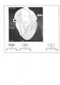
図7(A)に示した例のように、第1の実施形態における端末装置140は、立体表示モニタ142を有し、ワークステーション130によって生成された視差画像群を立体表示モニタ142に表示する。ここでは、端末装置140は、被検体の頭部を示す視差画像群を立体表示モニタ142に表示する。これにより、端末装置140の観察者は、被検体の頭部を示す立体画像I11を立体視することができる。そして、端末装置140は、観察者から、立体画像I11のうち開頭する領域である切開領域の指定を受け付ける。ここでは、端末装置140は、図7(A)に示した切開領域K11を受け付けるものとする。かかる場合に、端末装置140は、切開領域K11をワークステーション130に送信する。
As in the example illustrated in FIG. 7A, the terminal device 140 according to the first embodiment includes the stereoscopic display monitor 142, and displays the parallax image group generated by the workstation 130 on the stereoscopic display monitor 142. . Here, the terminal device 140 displays a parallax image group indicating the head of the subject on the stereoscopic display monitor 142. Thereby, the observer of the terminal device 140 can stereoscopically view the stereoscopic image I11 indicating the head of the subject. And the terminal device 140 receives designation | designated of the incision area | region which is an area | region to open in the stereo image I11 from the observer. Here, it is assumed that the terminal device 140 receives the incision region K11 illustrated in FIG. In such a case, the terminal device 140 transmits the incision region K11 to the workstation 130.
ワークステーション130は、端末装置140から切開領域K11を受信した場合に、開頭後における頭部内部の状態を推定する。具体的には、ワークステーション130は、開頭部位K11により開頭された場合における頭部内部の脳や血管等の位置変動を推定する。そして、ワークステーション130は、かかる推定結果に基づいて、脳や血管等の位置を変動させた後のボリュームデータを生成し、かかるボリュームデータに対してレンダリング処理を行うことにより、新たな視差画像群を生成する。そして、ワークステーション130は、新たに生成した視差画像群を端末装置140に送信する。
When the workstation 130 receives the incision region K11 from the terminal device 140, the workstation 130 estimates the state inside the head after the craniotomy. Specifically, the workstation 130 estimates the positional fluctuation of the brain, blood vessels, and the like inside the head when the craniotomy site K11 is opened. Then, the workstation 130 generates volume data after changing the positions of the brain, blood vessels, and the like based on the estimation result, and performs a rendering process on the volume data, thereby creating a new parallax image group. Is generated. Then, the workstation 130 transmits the newly generated parallax image group to the terminal device 140.
端末装置140は、ワークステーション130から受信した視差画像群を立体表示モニタ142に表示することで、図7(B)に示した例のように、開頭後における被検体の頭部を示す立体画像I12を表示する。これにより、医師等の観察者は、開頭後における頭部内部の状態を立体視することができ、この結果、開頭することで位置変動した脳や血管等の位置関係を術前に把握することが可能になる。
The terminal device 140 displays the parallax image group received from the workstation 130 on the stereoscopic display monitor 142, so that the stereoscopic image showing the head of the subject after opening is displayed as in the example illustrated in FIG. 7B. I12 is displayed. As a result, an observer such as a doctor can stereoscopically view the state inside the head after craniotomy, and as a result, grasp the positional relationship of the brain, blood vessels, etc. whose position has changed by craniotomy before the operation. Is possible.
以下に、このような第1の実施形態におけるワークステーション130及び端末装置140について詳細に説明する。なお、第1の実施形態では、医用画像診断装置110がX線CT装置である場合を例に挙げて説明する。ただし、医用画像診断装置110は、MRI装置や超音波診断装置であってもよく、以下の説明で記載するCT値は、パルスシーケンス毎に対応付けられたMR信号の強度や、超音波の反射波データ等であってもよい。
Hereinafter, the workstation 130 and the terminal device 140 in the first embodiment will be described in detail. In the first embodiment, a case where the medical image diagnostic apparatus 110 is an X-ray CT apparatus will be described as an example. However, the medical image diagnostic apparatus 110 may be an MRI apparatus or an ultrasonic diagnostic apparatus, and the CT value described in the following explanation is based on the intensity of an MR signal associated with each pulse sequence or the reflection of an ultrasonic wave. It may be wave data or the like.
まず、図8を用いて、第1の実施形態における端末装置140について説明する。図8は、第1の実施形態における端末装置140を説明するための図である。図8に例示するように、第1の実施形態における端末装置140は、入力部141と、立体表示モニタ142と、通信部143と、記憶部144と、制御部145とを有する。
First, the terminal device 140 according to the first embodiment will be described with reference to FIG. FIG. 8 is a diagram for explaining the terminal device 140 according to the first embodiment. As illustrated in FIG. 8, the terminal device 140 according to the first embodiment includes an input unit 141, a stereoscopic display monitor 142, a communication unit 143, a storage unit 144, and a control unit 145.
入力部141は、マウスやトラックボール等のポインティングデバイスや、キーボード等の情報入力デバイスであり、端末装置140に対する各種操作の入力を操作者から受け付ける。例えば、入力部141は、立体視要求として、操作者が立体視を要望するボリュームデータを指定するための患者ID、検査ID、装置ID、シリーズID等の入力を受け付ける。また、第1の実施形態における入力部141は、立体表示モニタ142に立体画像が表示されている状態において、切開(開頭、開胸、開腹等)を行う領域である切開領域の設定を受け付ける。
The input unit 141 is a pointing device such as a mouse or a trackball, or an information input device such as a keyboard, and receives input of various operations on the terminal device 140 from an operator. For example, the input unit 141 accepts input of a patient ID, an examination ID, a device ID, a series ID, and the like for designating volume data for which the operator desires stereoscopic vision as a stereoscopic vision request. In addition, the input unit 141 according to the first embodiment accepts setting of an incision area that is an area for performing incision (craniotomy, thoracotomy, open abdomen, and the like) in a state where a stereoscopic image is displayed on the stereoscopic display monitor 142.
立体表示モニタ142は、液晶パネル等であり、各種情報を表示する。具体的には、第1の実施形態に係る立体表示モニタ142は、操作者から各種操作を受け付けるためのGUI(Graphical User Interface)や、視差画像群等を表示する。例えば、立体表示モニタ142は、図2A及び図2Bを用いて説明した立体表示モニタ(以下、2視差モニタと記載する)や、図6を用いて説明した立体表示モニタ(以下、9視差モニタと記載する)である。以下では、立体表示モニタ142が9視差モニタである場合について説明する。
The stereoscopic display monitor 142 is a liquid crystal panel or the like and displays various information. Specifically, the stereoscopic display monitor 142 according to the first embodiment displays a GUI (Graphical User Interface) for receiving various operations from the operator, a parallax image group, and the like. For example, the stereoscopic display monitor 142 may be a stereoscopic display monitor (hereinafter referred to as a 2-parallax monitor) described with reference to FIGS. 2A and 2B, or a stereoscopic display monitor (hereinafter referred to as a 9-parallax monitor) described with reference to FIG. Described). Hereinafter, a case where the stereoscopic display monitor 142 is a nine-parallax monitor will be described.
通信部143は、NIC(Network Interface Card)等であり、他の装置との間で通信を行う。具体的には、第1の実施形態に係る通信部143は、入力部141が受け付けた立体視要求をワークステーション130に送信する。また、第1の実施形態に係る通信部143は、立体視要求に応じてワークステーション130が送信した視差画像群を受信する。
The communication unit 143 is a NIC (Network Interface Card) or the like, and communicates with other devices. Specifically, the communication unit 143 according to the first embodiment transmits the stereoscopic request received by the input unit 141 to the workstation 130. Further, the communication unit 143 according to the first embodiment receives a parallax image group transmitted by the workstation 130 in response to a stereoscopic request.
記憶部144は、ハードディスク、半導体メモリ素子等であり、各種情報を記憶する。具体的には、第1の実施形態に係る記憶部144は、通信部143を介してワークステーション130から取得した視差画像群を記憶する。また、記憶部144は、通信部143を介してワークステーション130から取得した視差画像群の付帯情報(視差数、解像度、ボリューム空間情報等)も記憶する。
The storage unit 144 is a hard disk, a semiconductor memory element, or the like, and stores various types of information. Specifically, the storage unit 144 according to the first embodiment stores a parallax image group acquired from the workstation 130 via the communication unit 143. The storage unit 144 also stores incidental information (number of parallaxes, resolution, volume space information, etc.) of the parallax image group acquired from the workstation 130 via the communication unit 143.
制御部145は、CPU、MPUやGPU等の電子回路、ASICやFPGA等の集積回路であり、端末装置140の全体制御を行う。例えば、制御部145は、ワークステーション130との間で通信部143を介して行われる立体視要求や視差画像群の送受信を制御する。また、例えば、制御部145は、視差画像群の記憶部144への格納や、視差画像群の記憶部144からの読み込みを制御する。
The control unit 145 is an electronic circuit such as a CPU, MPU, or GPU, or an integrated circuit such as an ASIC or FPGA, and performs overall control of the terminal device 140. For example, the control unit 145 controls transmission / reception of a stereoscopic request and a parallax image group performed with the workstation 130 via the communication unit 143. For example, the control unit 145 controls storage of the parallax image group in the storage unit 144 and reading of the parallax image group from the storage unit 144.
かかる制御部145は、図8に例示するように、表示制御部1451と、受付部1452とを有する。表示制御部1451は、ワークステーション130から受信した視差画像群を立体表示モニタ142に表示させる。これにより、立体表示モニタ142には視差画像群が表示され、かかる立体表示モニタ142の観察者は、立体視可能な立体画像を観察することができる。
The control unit 145 includes a display control unit 1451 and a reception unit 1452 as illustrated in FIG. The display control unit 1451 displays the parallax image group received from the workstation 130 on the stereoscopic display monitor 142. Thereby, the parallax image group is displayed on the stereoscopic display monitor 142, and an observer of the stereoscopic display monitor 142 can observe a stereoscopically viewable stereoscopic image.
受付部1452は、立体表示モニタ142に表示されている立体画像の切開領域の設定を受け付ける。具体的には、第1の実施形態における受付部1452は、ポインティングデバイス等の入力部141を用いて立体画像の所定の領域が切開領域として指定された場合に、立体画像が表示されている3次元空間(以下、「立体画像空間」と表記する場合がある)における切開領域の座標を入力部141から受け付ける。そして、受付部1452は、後述する座標変換式を用いて、立体画像空間における切開領域の座標をボリュームデータが配置される空間(以下、「ボリュームデータ空間」と表記する場合がある)における座標に変換する。そして、受付部1452は、ボリュームデータ空間における切開領域の座標をワークステーション130に送信する。
The reception unit 1452 receives the setting of the incision region of the stereoscopic image displayed on the stereoscopic display monitor 142. Specifically, the reception unit 1452 in the first embodiment displays a stereoscopic image when a predetermined region of the stereoscopic image is designated as an incision region using the input unit 141 such as a pointing device. Coordinates of the incision region in the dimensional space (hereinafter sometimes referred to as “stereoscopic image space”) are received from the input unit 141. Then, the reception unit 1452 converts the coordinates of the incision region in the stereoscopic image space into coordinates in a space in which volume data is arranged (hereinafter sometimes referred to as “volume data space”) using a coordinate conversion formula described later. Convert. Then, the reception unit 1452 transmits the coordinates of the incision area in the volume data space to the workstation 130.
なお、受付部1452は、上述したように、ワークステーション130から視差画像群に関する付帯情報として、視差画像群の生成元となったボリュームデータが配置される3次元空間に関するボリューム空間情報を取得する。受付部1452は、かかるボリューム空間情報が示す3次元空間を上記のボリュームデータ空間とする。
In addition, as described above, the reception unit 1452 acquires volume space information related to a three-dimensional space in which the volume data that is the generation source of the parallax image group is arranged as supplementary information related to the parallax image group from the workstation 130. The receiving unit 1452 sets the three-dimensional space indicated by the volume space information as the volume data space.
ここで、立体画像空間とボリュームデータ空間とでは座標系が異なるので、受付部1452は、所定の座標変換式を用いて、立体画像空間に対応するボリュームデータ空間の座標を取得する。以下に、図9を用いて、立体画像空間とボリュームデータ空間との対応関係について説明する。図9は、立体画像空間とボリュームデータ空間との対応関係の一例を示す図である。図9(A)は、ボリュームデータを示し、図9(B)は、立体表示モニタ142によって表示される立体画像を示す。また、図9(A)における座標301と座標302と距離303とは、それぞれ、図9(B)における座標304と座標305と距離306とに対応する。
Here, since the coordinate system is different between the stereoscopic image space and the volume data space, the accepting unit 1452 acquires the coordinates of the volume data space corresponding to the stereoscopic image space using a predetermined coordinate conversion formula. Hereinafter, the correspondence between the stereoscopic image space and the volume data space will be described with reference to FIG. FIG. 9 is a diagram illustrating an example of a correspondence relationship between the stereoscopic image space and the volume data space. FIG. 9A shows volume data, and FIG. 9B shows a stereoscopic image displayed by the stereoscopic display monitor 142. Further, the coordinates 301, 302, and distance 303 in FIG. 9A correspond to the coordinates 304, 305, and distance 306 in FIG. 9B, respectively.
図9に示すように、ボリュームデータが配置されるボリュームデータ空間と、立体画像が表示されている立体画像空間とは、座標系が異なる。具体的には、図9(B)に示す立体画像は、図9(A)に示すボリュームデータと比較して、奥行き方向(z方向)が狭くなっている。言い換えると、図9(B)に示した立体画像では、図9(A)に示されたボリュームデータの奥行き方向の成分が、圧縮された上で表示されている。この場合、図9(B)に示すように、座標304と座標305との間の距離306は、図9(A)における座標301と座標302との間の距離303と比較して、圧縮される分短くなる。
As shown in FIG. 9, the coordinate system is different between the volume data space in which the volume data is arranged and the stereoscopic image space in which the stereoscopic image is displayed. Specifically, the stereoscopic image shown in FIG. 9B is narrower in the depth direction (z direction) than the volume data shown in FIG. In other words, in the stereoscopic image shown in FIG. 9B, the component in the depth direction of the volume data shown in FIG. 9A is displayed after being compressed. In this case, as shown in FIG. 9B, the distance 306 between the coordinates 304 and the coordinates 305 is compressed as compared with the distance 303 between the coordinates 301 and the coordinates 302 in FIG. It gets shorter.
このような立体画像空間座標とボリュームデータ空間座標との対応関係は、立体画像のスケールや視差角、視線方向(レンダリング時の視線方向、又は、立体画像観察時の視線方向)等により一意に決定され、例えば、以下の(数1)のような形で表現することが可能となる。
Such correspondence between the stereoscopic image space coordinates and the volume data space coordinates is uniquely determined by the scale and parallax angle of the stereoscopic image, the line-of-sight direction (the line-of-sight direction during rendering or the line-of-sight direction during stereoscopic image observation), and the like. For example, it can be expressed in the following form (Equation 1).
(数1)=(x1、y1、z1)=F(x2、y2、z2)
(Equation 1) = (x1, y1, z1) = F (x2, y2, z2)
(数1)において、「x2」「y2」「z2」は、それぞれ、立体画像空間座標を示す。また、「x1」「y1」「z1」は、それぞれ、ボリュームデータ空間座標を示す。また、関数「F」は、立体画像のスケールや視野角、視線方向等により一意に決定される関数である。すなわち、受付部1452は、(数1)を用いることで、立体画像空間座標とボリュームデータ空間座標との対応関係を取得することができる。なお、関数「F」は、立体画像のスケールや視野角、視線方向(レンダリング時の視線方向、又は、立体画像観察時の視線方向)等が変更されるごとに受付部1452により生成される。例えば、回転、平行移動、拡大、縮小を変換する関数「F」として(数2)に示したアフィン変換が用いられる。
In (Equation 1), “x2”, “y2”, and “z2” respectively indicate stereoscopic image space coordinates. “X1”, “y1”, and “z1” indicate volume data space coordinates, respectively. The function “F” is a function that is uniquely determined by the scale, viewing angle, line-of-sight direction, and the like of the stereoscopic image. That is, the reception unit 1452 can acquire the correspondence between the stereoscopic image space coordinates and the volume data space coordinates by using (Equation 1). The function “F” is generated by the receiving unit 1452 every time the stereoscopic image scale, viewing angle, line-of-sight direction (line-of-sight direction during rendering or line-of-sight direction during stereoscopic image observation), and the like are changed. For example, the affine transformation shown in (Expression 2) is used as the function “F” for transforming rotation, translation, enlargement, and reduction.
(数2)
x1=a*x2+b*y2+c*z3+d
y1=e*x2+f*y2+g*z3+h
z1=i*x2+j*y2+k*z3+l
(a~lは変換係数) (Equation 2)
x1 = a * x2 + b * y2 + c * z3 + d
y1 = e * x2 + f * y2 + g * z3 + h
z1 = i * x2 + j * y2 + k * z3 + l
(A to l are conversion coefficients)
x1=a*x2+b*y2+c*z3+d
y1=e*x2+f*y2+g*z3+h
z1=i*x2+j*y2+k*z3+l
(a~lは変換係数) (Equation 2)
x1 = a * x2 + b * y2 + c * z3 + d
y1 = e * x2 + f * y2 + g * z3 + h
z1 = i * x2 + j * y2 + k * z3 + l
(A to l are conversion coefficients)
なお、上述した説明では、受付部1452が、関数「F」に基づいてボリュームデータ空間の座標を取得する例を示したが、これに限定されるものではない。例えば、端末装置140が、立体画像空間座標とボリュームデータ空間座標とが対応付けられたテーブルである座標テーブルを有し、受付部1452が、立体画像空間座標を検索キーとして座標テーブルを検索することで、立体画像空間座標に対応するボリュームデータ空間座標を取得してもよい。
In the above description, the example in which the reception unit 1452 acquires the coordinates of the volume data space based on the function “F” is shown, but the present invention is not limited to this. For example, the terminal device 140 has a coordinate table that is a table in which stereoscopic image space coordinates and volume data space coordinates are associated, and the reception unit 1452 searches the coordinate table using the stereoscopic image space coordinates as search keys. Thus, the volume data space coordinates corresponding to the stereoscopic image space coordinates may be acquired.
次に、図10を用いて、第1の実施形態におけるワークステーション130が有する制御部135について説明する。図10は、第1の実施形態における制御部135の構成例を説明するための図である。図10に例示するように、ワークステーション130の制御部135は、推定部1351と、レンダリング制御部1352と、表示制御部1353とを有する。
Next, the control unit 135 included in the workstation 130 according to the first embodiment will be described with reference to FIG. FIG. 10 is a diagram for explaining a configuration example of the control unit 135 in the first embodiment. As illustrated in FIG. 10, the control unit 135 of the workstation 130 includes an estimation unit 1351, a rendering control unit 1352, and a display control unit 1353.
推定部1351は、術中(例えば、開頭後、開胸後、開腹後)における被検体内の状態を推定する。具体的には、第1の実施形態における推定部1351は、端末装置140の受付部1452からボリュームデータ空間における切開領域の座標を受信した場合に、端末装置140の立体表示モニタ142に表示されている視差画像群の生成元となったボリュームデータに含まれる各ボクセルの位置変動を推定する。
The estimation unit 1351 estimates the state in the subject during the operation (for example, after craniotomy, after thoracotomy, and after laparotomy). Specifically, the estimation unit 1351 in the first embodiment is displayed on the stereoscopic display monitor 142 of the terminal device 140 when the coordinates of the incision area in the volume data space are received from the reception unit 1452 of the terminal device 140. The position variation of each voxel included in the volume data that is the generation source of the present parallax image group is estimated.
より具体的に説明すると、推定部1351は、受付部1452から受信した切開領域の座標に位置するボリュームデータ内のボクセルのうち、被検体の表面部位(皮膚、頭蓋骨、筋肉等)を示すボクセルを取り除く。例えば、推定部1351は、かかる表面部位を示すボクセルのCT値を、空気を示すCT値に置き換える。そして、推定部1351は、表面部位を取り除いた後に、以下に示す各種パラメータ(X1)~(X7)等に基づいて、ボリュームデータ内の各ボクセルの位置変動を推定する。なお、ここでいう「位置変動」とは、ボクセルの移動ベクトル(移動方向及び移動量)と膨張率とを含む。
More specifically, the estimation unit 1351 determines a voxel indicating the surface portion (skin, skull, muscle, etc.) of the subject among the voxels in the volume data located at the coordinates of the incision region received from the reception unit 1452. remove. For example, the estimation unit 1351 replaces the CT value of the voxel indicating the surface portion with a CT value indicating air. Then, after removing the surface portion, the estimation unit 1351 estimates the position variation of each voxel in the volume data based on various parameters (X1) to (X7) shown below. Here, “position fluctuation” includes a voxel movement vector (movement direction and movement amount) and an expansion rate.
(X1)表面部位から臓器等に加わっている圧力(内圧)
(X2)CT値
(X3)切開領域の大きさ
(X4)切開領域との距離
(X5)隣接するボクセルのCT値
(X6)血流速、血流量、血圧
(X7)被検体情報 (X1) Pressure applied to the organ etc. from the surface part (internal pressure)
(X2) CT value (X3) Size of incision area (X4) Distance to incision area (X5) CT value of adjacent voxel (X6) Blood flow velocity, blood flow volume, blood pressure (X7) Subject information
上記(X1)について説明する。被検体内の各種臓器は、被検体の表面に存在する骨や筋肉等の表面部位に囲まれており、かかる表面部位から圧力を受ける。例えば、開頭前の脳は頭蓋骨に囲まれており、頭蓋骨からの圧力を受けている状態である。上記(X1)は、被検体内部に加わっている圧力(以下、「内圧」と表記する場合がある)を示し、上記例の場合には、頭蓋骨が存在することで脳に加わる圧力を示す。被検体内の各種臓器は、表面部位が取り除かれた場合に、かかる表面部位から内圧を受けなくなるので、取り除かれた表面部位の方向に移動しやすく更に膨張しやすい。このようなことから、推定部1351は、各ボクセルの位置変動を推定する際に、上記(X1)内圧を用いる。なお、各部位(ボクセル)に加わる内圧は、各部位(ボクセル)と表面部位との距離や、表面部位の硬さ等に基づいて予め算出される。
The above (X1) will be described. Various organs in the subject are surrounded by surface portions such as bones and muscles existing on the surface of the subject and receive pressure from the surface portions. For example, the brain before craniotomy is surrounded by the skull and is in a state of receiving pressure from the skull. The (X1) indicates the pressure applied to the inside of the subject (hereinafter may be referred to as “internal pressure”), and in the case of the above example, indicates the pressure applied to the brain due to the presence of the skull. Since various internal organs in the subject are not subjected to internal pressure from the surface portion when the surface portion is removed, they are easily moved in the direction of the removed surface portion and further easily expanded. For this reason, the estimation unit 1351 uses the internal pressure (X1) when estimating the position variation of each voxel. The internal pressure applied to each part (voxel) is calculated in advance based on the distance between each part (voxel) and the surface part, the hardness of the surface part, and the like.
また、上記(X2)について説明する。CT値は、臓器の特性を示す値であり、例えば、臓器の硬さを示す。一般には、CT値が高い臓器ほど、硬い臓器であることを示す。ここで、硬い臓器ほど移動しにくく膨張しにくいので、CT値の高低は、各種臓器の移動量や膨張率の指標となる。このようなことから、推定部1351は、各ボクセルの位置変動を推定する際に、上記(X2)CT値を用いる。
Also, the above (X2) will be described. The CT value is a value indicating the characteristics of the organ, and indicates, for example, the hardness of the organ. In general, an organ with a higher CT value indicates a harder organ. Here, the harder the organ, the harder it is to move and the harder it is to expand, so the level of the CT value is an indicator of the amount of movement and the expansion rate of various organs. For this reason, the estimation unit 1351 uses the (X2) CT value when estimating the position variation of each voxel.
また、上記(X3)について説明する。切開領域の大きさは、上記(X1)内圧に乗算されることにより、被検体内の各種臓器に加わる力の総和となる。一般には、切開領域が大きいほど、被検体内の各種臓器の移動量及び膨張率は大きくなると考えられる。このようなことから、推定部1351は、各ボクセルの位置変動を推定する際に、上記(X3)切開領域の大きさを用いる。
Also, the above (X3) will be described. The size of the incision region is the sum of forces applied to various organs in the subject by multiplying the (X1) internal pressure. In general, it is considered that the larger the incision area, the larger the moving amount and the expansion rate of various organs in the subject. For this reason, the estimation unit 1351 uses the size of the (X3) incision region when estimating the position variation of each voxel.
また、上記(X4)について説明する。切開領域との距離が近い臓器ほど、上記(X1)内圧の影響を大きく受け、切開領域との距離が遠い臓器ほど、上記(X1)内圧の影響を受けにくくなる。すなわち、開頭等がされた場合における臓器の移動量及び膨張率は、切開領域との距離によって異なる。このようなことから、推定部1351は、各ボクセルの位置変動を推定する際に、上記(X4)切開領域との距離を用いる。
Also, the above (X4) will be described. An organ closer to the incision region is more affected by the internal pressure (X1), and an organ farther from the incision region is less affected by the internal pressure (X1). That is, the amount of movement and expansion rate of the organ when craniotomy or the like varies depending on the distance from the incision region. For this reason, the estimation unit 1351 uses the distance from the (X4) incision region when estimating the position variation of each voxel.
また、上記(X5)について説明する。移動しやすい臓器であっても、隣接する部位に骨等の硬い部位が存在する場合には、かかる臓器は移動しにくくなる。例えば、開頭が行われた部位と移動推定対象の臓器との間に硬い部位が存在する場合には、かかる移動推定対象の臓器は、移動しにくく更に膨張しにくい。このようなことから、推定部1351は、各ボクセルの位置変動を推定する際に、上記(X5)隣接するボクセルのCT値を用いる。
Also, the above (X5) will be described. Even if the organ is easy to move, if a hard part such as a bone exists in an adjacent part, the organ becomes difficult to move. For example, when a hard part exists between the part where craniotomy has been performed and the movement estimation target organ, the movement estimation target organ is difficult to move and further difficult to expand. For this reason, the estimation unit 1351 uses the CT value of the (X5) adjacent voxel when estimating the position variation of each voxel.
また、上記(X6)について説明する。血管は、血流速(血液の流れる速度)や血流量(血液の流れる量)や血圧によって移動量や膨張率が変動する。例えば、開頭が行われた場合、血流速が速く、血流量が多く、血圧が高い血管ほど、開頭部から外部方向へ移動しやすい。このようなことから、推定部1351は、各ボクセルのうち、血管の位置変動を推定する際に、上記(X6)血流速、血流量、血圧を用いてもよい。
Also, the above (X6) will be described. The movement amount and the expansion rate of the blood vessel vary depending on the blood flow velocity (blood flow speed), blood flow volume (blood flow volume), and blood pressure. For example, when craniotomy is performed, the blood flow rate is faster, the blood flow volume is higher, and the blood pressure is higher, the blood vessel is easier to move from the craniotomy toward the outside. For this reason, the estimation unit 1351 may use the above (X6) blood flow velocity, blood flow volume, and blood pressure when estimating the blood vessel position fluctuation among the voxels.
また、上記(X7)について説明する。各臓器は被検体(患者)の特性によって移動量や膨張率が変動する。例えば、被検体の年齢、性別、体重、体脂肪率等の被検体情報によって、各臓器における移動量や膨張率の平均値等が得られる。このようなことから、推定部1351は、上記(X7)被検体情報を用いて、各ボクセルの移動量や膨張率に重み付けをしてもよい。
Also, the above (X7) will be described. The movement amount and expansion rate of each organ vary depending on the characteristics of the subject (patient). For example, based on the subject information such as the age, sex, weight, and body fat percentage of the subject, the movement amount and the average value of the expansion rate in each organ can be obtained. For this reason, the estimation unit 1351 may weight the moving amount and the expansion rate of each voxel using the (X7) subject information.
第1の実施形態における推定部1351は、上述したような各種パラメータ(X1)~(X7)等を変数とする関数を用いて、ボリュームデータ内の各ボクセルの移動ベクトル及び膨張率を推定する。
The estimation unit 1351 in the first embodiment estimates the movement vector and the expansion rate of each voxel in the volume data using a function having the various parameters (X1) to (X7) as variables as described above.
ここで、図11を用いて、推定部1351による推定処理の一例を説明する。図11は、第1の実施形態における推定部1351による推定処理の一例を説明するための図である。図11に示した例において、ワークステーション130は、レンダリング処理部136によってボリュームデータVD10から生成された視差画像群を端末装置140に送信する。すなわち、端末装置140は、ボリュームデータVD10から生成された視差画像群を立体表示モニタ142に表示し、かかる視差画像群によって表示される立体画像に対して切開領域を受け付ける。ここでは、端末装置140は、図11に示した切開領域K11を受け付けたものとする。かかる場合に、ワークステーション130の推定部1351は、ボリュームデータVD10に含まれる各ボクセルの移動ベクトル及び膨張率を推定する。図11(B)には、全てのボクセルを図示せずに、ボリュームデータVD10のうちボリュームデータVD11を例に挙げて、推定部1351による推定処理について説明する。
Here, an example of the estimation process by the estimation unit 1351 will be described with reference to FIG. FIG. 11 is a diagram for describing an example of an estimation process performed by the estimation unit 1351 according to the first embodiment. In the example illustrated in FIG. 11, the workstation 130 transmits the parallax image group generated from the volume data VD10 by the rendering processing unit 136 to the terminal device 140. That is, the terminal device 140 displays the parallax image group generated from the volume data VD10 on the stereoscopic display monitor 142, and accepts an incision region for the stereoscopic image displayed by the parallax image group. Here, it is assumed that the terminal device 140 has received the incision region K11 illustrated in FIG. In such a case, the estimation unit 1351 of the workstation 130 estimates the movement vector and expansion rate of each voxel included in the volume data VD10. In FIG. 11B, not all the voxels are shown, but the estimation process by the estimation unit 1351 will be described using the volume data VD11 of the volume data VD10 as an example.
図11(B)に示した例において、1個の矩形は、1個のボクセルを示す。また、斜線が付されている矩形(ボクセル)は、頭蓋骨であるものとする。ここでは、切開領域K11を受け付けたので、推定部1351は、斜線付きボクセルのうち、図11(B)に示した切開領域K11よりも上に配置されているボクセルを空気等のCT値に置き換える。そして、推定部1351は、上述したパラメータ(X1)~(X7)等により算出される移動推定用の関数を用いて、各ボクセルの移動ベクトル及び膨張率を推定する。例えば、推定部1351は、各ボクセルについて、空気等のCT値に置き換える前のボクセルから受ける内圧等を用いて移動推定用の関数を算出したりする。図11(B)に示した例では、推定部1351は、取り除かれた表面部位の方向にボクセル全体が移動することを推定している。また、推定部1351は、斜線付きボクセル(頭蓋骨)に近いボクセルほど移動量が大きく、斜線付きボクセル(頭蓋骨)に遠いボクセルほど移動量が小さくなることを推定している。なお、図11に示した例では、各ボクセルがxy平面に対して平行移動するようにも見えるが、推定部1351は、実際には、各ボクセルの移動方向を3次元に推定する。
In the example shown in FIG. 11B, one rectangle represents one voxel. In addition, a rectangle (voxel) that is shaded is a skull. Here, since the incision region K11 has been received, the estimation unit 1351 replaces the voxels with diagonal lines above the incision region K11 shown in FIG. 11B with CT values such as air. . Then, the estimation unit 1351 estimates the movement vector and the expansion rate of each voxel using the movement estimation function calculated by the parameters (X1) to (X7) described above. For example, the estimation unit 1351 calculates a function for movement estimation for each voxel using an internal pressure received from the voxel before being replaced with a CT value such as air. In the example shown in FIG. 11B, the estimation unit 1351 estimates that the entire voxel moves in the direction of the removed surface portion. Further, the estimation unit 1351 estimates that the movement amount is larger as the voxel is closer to the hatched voxel (skull), and the movement amount is smaller as the voxel is farther from the hatched voxel (skull). In the example shown in FIG. 11, each voxel seems to move in parallel with respect to the xy plane, but the estimation unit 1351 actually estimates the moving direction of each voxel in three dimensions.
このようにして、推定部1351は、ボリュームデータVD11だけでなく、ボリュームデータVD10に含まれる各ボクセルについて移動ベクトルを推定する。さらに、図11には図示することを省略したが、推定部1351は、各ボクセルの膨張率についても推定する。
In this way, the estimation unit 1351 estimates a movement vector for each voxel included in the volume data VD10 as well as the volume data VD11. Furthermore, although not shown in FIG. 11, the estimation unit 1351 also estimates the expansion rate of each voxel.
図10の説明に戻って、レンダリング制御部1352は、レンダリング処理部136と協働してボリュームデータから視差画像群を生成する。具体的には、第1の実施形態におけるレンダリング制御部1352は、推定部1351による推定結果に基づいて、ボリュームデータを生成し、生成したボリュームデータに対してレンダリング処理を行うようにレンダリング処理部136を制御する。このとき、レンダリング制御部1352は、端末装置140の立体表示モニタ142に表示されている視差画像群の生成元となったボリュームデータに対して、推定部1351によって推定された各ボクセルの移動ベクトル及び膨張率を反映することにより、新たなボリュームデータを生成する。なお、以下では、推定結果が反映されたボリュームデータを「仮想ボリュームデータ」と表記する場合がある。
10, the rendering control unit 1352 generates a parallax image group from the volume data in cooperation with the rendering processing unit 136. Specifically, the rendering control unit 1352 according to the first embodiment generates volume data based on the estimation result by the estimation unit 1351, and performs a rendering process on the generated volume data. To control. At this time, the rendering control unit 1352 uses the movement vector of each voxel estimated by the estimation unit 1351 and the volume data that is the generation source of the parallax image group displayed on the stereoscopic display monitor 142 of the terminal device 140. New volume data is generated by reflecting the expansion rate. In the following description, the volume data reflecting the estimation result may be referred to as “virtual volume data”.
ここで、図11を用いて、レンダリング制御部1352による仮想ボリュームデータの生成処理の一例を説明する。図11(B)に示した例において、ボクセルV10に注目すると、推定部1351は、ボクセルV10がボクセルV11とボクセルV12との間の位置に移動することを推定している。また、ここでは、推定部1351は、ボクセルV10の膨張率として「2倍(200%)」を推定したものとする。かかる場合に、レンダリング制御部1352は、ボクセルV10をボクセルV11とボクセルV12との間の位置に配置するとともに、ボクセルV10のサイズを2倍にする。例えば、レンダリング制御部1352は、ボクセルV10をボクセルV11及びボクセルV12に配置する。このようにして、レンダリング制御部1352は、推定部1351による推定結果に基づいて、各ボクセルの配置を変更することにより、仮想ボリュームデータを生成する。
Here, an example of virtual volume data generation processing by the rendering control unit 1352 will be described with reference to FIG. In the example shown in FIG. 11B, when attention is paid to the voxel V10, the estimation unit 1351 estimates that the voxel V10 moves to a position between the voxel V11 and the voxel V12. Here, it is assumed that the estimation unit 1351 estimates “2 times (200%)” as the expansion rate of the voxel V10. In such a case, the rendering control unit 1352 arranges the voxel V10 at a position between the voxel V11 and the voxel V12, and doubles the size of the voxel V10. For example, the rendering control unit 1352 arranges the voxel V10 in the voxel V11 and the voxel V12. In this way, the rendering control unit 1352 generates virtual volume data by changing the arrangement of each voxel based on the estimation result by the estimation unit 1351.
図10の説明に戻って、表示制御部1353は、レンダリング処理部136によって生成される視差画像群を端末装置140に送信することで、立体表示モニタ142に視差画像群を表示させる。また、第1の実施形態における表示制御部1353は、レンダリング制御部1352によって制御された結果、レンダリング処理部136によって新たな視差画像群が生成された場合には、かかる視差画像群を端末装置140に送信する。これにより、端末装置140は、例えば図7(B)に示したように、開頭後における頭部内部を示す立体画像I12等を立体表示モニタ142に表示する。
Returning to the description of FIG. 10, the display control unit 1353 causes the stereoscopic display monitor 142 to display the parallax image group by transmitting the parallax image group generated by the rendering processing unit 136 to the terminal device 140. In addition, when the rendering processing unit 136 generates a new parallax image group as a result of the control by the rendering control unit 1352, the display control unit 1353 in the first embodiment displays the parallax image group as a terminal device 140. Send to. As a result, the terminal device 140 displays a stereoscopic image I12 and the like showing the inside of the head after the head opening on the stereoscopic display monitor 142 as shown in FIG. 7B, for example.
次に、図12を用いて、第1の実施形態におけるワークステーション130及び端末装置140による処理の流れの一例を示す。図12は、第1の実施形態における画像処理システムによる処理の流れの一例を示すシーケンス図である。
Next, an example of the flow of processing by the workstation 130 and the terminal device 140 in the first embodiment will be described with reference to FIG. FIG. 12 is a sequence diagram illustrating an example of a processing flow by the image processing system according to the first embodiment.
図12に示すように、端末装置140は、観察者から立体視要求が入力されたか否かを判定する(ステップS101)。ここで、立体視要求が入力されない場合には(ステップS101否定)、端末装置140は、待機する。
As shown in FIG. 12, the terminal device 140 determines whether or not a stereoscopic view request is input from the observer (step S101). Here, when the stereoscopic view request is not input (No at Step S101), the terminal device 140 stands by.
一方、端末装置140は、立体視要求が入力された場合には(ステップS101肯定)、かかる立体視要求に対応する視差画像群をワークステーション130から取得する(ステップS102)。そして、表示制御部1451は、ワークステーション130から取得した視差画像群を立体表示モニタ142に表示する(ステップS103)。
On the other hand, when the stereoscopic request is input (Yes in step S101), the terminal device 140 acquires a parallax image group corresponding to the stereoscopic request from the workstation 130 (step S102). Then, the display control unit 1451 displays the parallax image group acquired from the workstation 130 on the stereoscopic display monitor 142 (step S103).
続いて、端末装置140の受付部1452は、立体表示モニタ142に表示されている立体画像に対する切開領域の設定を受け付けたか否かを判定する(ステップS104)。ここで、切開領域の設定を受け付けない場合には(ステップS104否定)、受付部1452は、切開領域の設定を受け付けるまで待機する。
Subsequently, the reception unit 1452 of the terminal device 140 determines whether or not an incision region setting for the stereoscopic image displayed on the stereoscopic display monitor 142 has been received (step S104). Here, when the setting of the incision area is not accepted (No at Step S104), the reception unit 1452 waits until the setting of the incision area is accepted.
一方、受付部1452は、切開領域の設定を受け付けた場合には(ステップS104肯定)、上述した関数「F」を用いて、立体画像空間における切開領域の座標に対応するボリュームデータ空間の座標を取得し、取得したボリュームデータ空間における切開領域の座標をワークステーション130に送信する(ステップS105)。
On the other hand, when accepting the setting of the incision area (Yes at step S104), the accepting unit 1452 uses the function “F” described above to obtain the coordinates of the volume data space corresponding to the coordinates of the incision area in the stereoscopic image space. The acquired coordinates of the incision area in the acquired volume data space are transmitted to the workstation 130 (step S105).
続いて、ワークステーション130の推定部1351は、端末装置140から受信した切開領域の座標に位置する被検体の表面部位を示すボクセルを取り除き、上記の各種パラメータ(X1)~(X7)等に基づいて、ボリュームデータ内の各ボクセルの位置変動(移動ベクトル及び膨張率)を推定する(ステップS106)。
Subsequently, the estimation unit 1351 of the workstation 130 removes the voxels indicating the surface portion of the subject located at the coordinates of the incision region received from the terminal device 140, and based on the various parameters (X1) to (X7) and the like described above. Then, the position variation (movement vector and expansion rate) of each voxel in the volume data is estimated (step S106).
続いて、レンダリング制御部1352は、推定部1351によって推定された各ボクセルの移動ベクトル及び膨張率をボリュームデータに反映することにより、仮想ボリュームデータを生成する(ステップS107)。そして、レンダリング制御部1352は、仮想ボリュームデータに対してレンダリング処理を行うようにレンダリング処理部136を制御することで視差画像群を生成する(ステップS108)。そして、表示制御部1353は、レンダリング処理部136によって生成された視差画像群を端末装置140に送信する(ステップS109)。
Subsequently, the rendering control unit 1352 generates virtual volume data by reflecting the movement vector and expansion rate of each voxel estimated by the estimation unit 1351 in the volume data (step S107). Then, the rendering control unit 1352 generates a parallax image group by controlling the rendering processing unit 136 so as to perform rendering processing on the virtual volume data (step S108). Then, the display control unit 1353 transmits the parallax image group generated by the rendering processing unit 136 to the terminal device 140 (step S109).
端末装置140の表示制御部1451は、ワークステーション130から受信した視差画像群を立体表示モニタ142に表示する(ステップS110)。これにより、立体表示モニタ142は、開頭後における立体画像を表示することができる。
The display control unit 1451 of the terminal device 140 displays the parallax image group received from the workstation 130 on the stereoscopic display monitor 142 (step S110). Thereby, the stereoscopic display monitor 142 can display the stereoscopic image after the opening.
上述してきたように、第1の実施形態によれば、切開後における被検体内部の状態を示す立体画像を表示することができる。この結果、医師等の観察者は、切開(開頭、開胸、開腹等)により位置変動する各種臓器の位置関係を術前に把握することができる。また、医師等の観察者は、例えば、切開領域の位置や大きさを変更することで、各切開領域に対応する被検体内部の状態を確認することができ、この結果、手術に適した切開領域の位置や大きさを術前に決定することができる。
As described above, according to the first embodiment, it is possible to display a stereoscopic image indicating the state inside the subject after the incision. As a result, an observer such as a doctor can grasp the positional relationship of various organs whose positions change due to incision (craniotomy, thoracotomy, laparotomy, etc.) before the operation. In addition, an observer such as a doctor can confirm the internal state of the subject corresponding to each incision region by changing the position and size of the incision region, for example. The position and size of the area can be determined preoperatively.
なお、第1の実施形態は、上記の実施形態に限られず、以下に示すいくつかの変形例を含む態様の実施形態であってもよい。以下に、第1の実施形態の変形例について説明する。
In addition, 1st Embodiment is not restricted to said embodiment, Embodiment of the aspect containing the some modification shown below may be sufficient. Below, the modification of 1st Embodiment is demonstrated.
[切開領域の自動設定]
上記第1の実施形態において、ワークステーション130は、観察者に指定された切開領域に基づいて、各種臓器の移動ベクトル及び膨張率を推定した。しかし、ワークステーション130は、切開領域をランダムに設定し、各切開領域において上述した推定部1351による推定処理を行い、各切開領域に対応する視差画像群を端末装置140に送信してもよい。そして、端末装置140は、ワークステーション130から受信した複数の視差画像群を並列的に立体表示モニタ142に表示してもよい。 [Automatic setting of incision area]
In the first embodiment, theworkstation 130 estimates the movement vectors and expansion rates of various organs based on the incision area designated by the observer. However, the workstation 130 may set incision areas at random, perform the estimation process by the estimation unit 1351 described above in each incision area, and transmit a parallax image group corresponding to each incision area to the terminal device 140. Then, the terminal device 140 may display the plurality of parallax image groups received from the workstation 130 on the stereoscopic display monitor 142 in parallel.
上記第1の実施形態において、ワークステーション130は、観察者に指定された切開領域に基づいて、各種臓器の移動ベクトル及び膨張率を推定した。しかし、ワークステーション130は、切開領域をランダムに設定し、各切開領域において上述した推定部1351による推定処理を行い、各切開領域に対応する視差画像群を端末装置140に送信してもよい。そして、端末装置140は、ワークステーション130から受信した複数の視差画像群を並列的に立体表示モニタ142に表示してもよい。 [Automatic setting of incision area]
In the first embodiment, the
また、ワークステーション130は、ランダムに設定した各切開領域のうち、移動量及び膨張率の平均値が所定の閾値よりも低い切開領域を選択し、選択した切開領域に対応する視差画像群を端末装置140に送信してもよい。これにより、医師等の観察者は、開頭等を行っても各種臓器の移動量及び膨張率が小さい切開領域を得ることができる。
In addition, the workstation 130 selects an incision region in which the average value of the movement amount and the expansion rate is lower than a predetermined threshold among the randomly set incision regions, and displays a parallax image group corresponding to the selected incision region. It may be transmitted to the device 140. Thereby, an observer such as a doctor can obtain an incision region having a small amount of movement and expansion rate of various organs even when craniotomy or the like is performed.
[臓器毎の移動推定]
上記第1の実施形態では、ボクセル毎に移動ベクトル及び膨張率を推定する例を示した。しかし、ワークステーション130は、ボリュームデータに対してセグメンテーション処理を行うことで、かかるボリュームデータに含まれる心臓、肺、血管等の臓器を抽出し、抽出した臓器単位で移動ベクトル及び膨張率を推定してもよい。そして、ワークステーション130は、仮想ボリュームデータを生成する場合に、同一の臓器を示すボクセル群を隣接する位置に配置するように制御してもよい。すなわち、ワークステーション130は、仮想ボリュームデータを生成する際には、同一の臓器である立体画像が分断しないように各ボクセルを配置する。 [Movement estimation for each organ]
In the said 1st Embodiment, the example which estimates a movement vector and an expansion rate for every voxel was shown. However, theworkstation 130 performs segmentation processing on the volume data to extract organs such as the heart, lungs, and blood vessels included in the volume data, and estimates the movement vector and the expansion rate for each extracted organ. May be. Then, when generating virtual volume data, the workstation 130 may perform control so that a group of voxels indicating the same organ is arranged at an adjacent position. That is, when generating virtual volume data, the workstation 130 arranges each voxel so that a stereoscopic image that is the same organ is not divided.
上記第1の実施形態では、ボクセル毎に移動ベクトル及び膨張率を推定する例を示した。しかし、ワークステーション130は、ボリュームデータに対してセグメンテーション処理を行うことで、かかるボリュームデータに含まれる心臓、肺、血管等の臓器を抽出し、抽出した臓器単位で移動ベクトル及び膨張率を推定してもよい。そして、ワークステーション130は、仮想ボリュームデータを生成する場合に、同一の臓器を示すボクセル群を隣接する位置に配置するように制御してもよい。すなわち、ワークステーション130は、仮想ボリュームデータを生成する際には、同一の臓器である立体画像が分断しないように各ボクセルを配置する。 [Movement estimation for each organ]
In the said 1st Embodiment, the example which estimates a movement vector and an expansion rate for every voxel was shown. However, the
[並列表示]
また、上記第1の実施形態において、端末装置140の表示制御部1451は、実際の被検体内を示す立体画像と、位置変動の推定結果が反映された立体画像とを並列表示してもよい。例えば、表示制御部1451は、図7に例示した立体画像I11と立体画像I12とを並列に表示してもよい。これにより、観察者は、術前及び術中における被検体内の状態を比較して観察することが可能になる。このような並列表示は、ワークステーション130が、立体画像I11を表示するための視差画像群と、立体画像I12を表示するための視差画像群とを端末装置140に送信することで実現できる。 [Parallel display]
In the first embodiment, thedisplay control unit 1451 of the terminal device 140 may display in parallel a stereoscopic image that shows the actual interior of the subject and a stereoscopic image that reflects the estimation result of the position variation. . For example, the display control unit 1451 may display the stereoscopic image I11 and the stereoscopic image I12 illustrated in FIG. 7 in parallel. Thereby, the observer can compare and observe the state in the subject before and during the operation. Such parallel display can be realized by the workstation 130 transmitting to the terminal device 140 a parallax image group for displaying the stereoscopic image I11 and a parallax image group for displaying the stereoscopic image I12.
また、上記第1の実施形態において、端末装置140の表示制御部1451は、実際の被検体内を示す立体画像と、位置変動の推定結果が反映された立体画像とを並列表示してもよい。例えば、表示制御部1451は、図7に例示した立体画像I11と立体画像I12とを並列に表示してもよい。これにより、観察者は、術前及び術中における被検体内の状態を比較して観察することが可能になる。このような並列表示は、ワークステーション130が、立体画像I11を表示するための視差画像群と、立体画像I12を表示するための視差画像群とを端末装置140に送信することで実現できる。 [Parallel display]
In the first embodiment, the
[特定表示1]
また、上記第1の実施形態において、レンダリング制御部1352は、推定部1351によって移動又は膨張することが推定されたボクセル群のみを抽出し、抽出したボクセル群によって形成されるボリュームデータ(以下、「特定ボリュームデータ」と表記する場合がある)から視差画像群を生成してもよい。かかる場合に、端末装置140の立体表示モニタ142は、移動又は膨張することが推定された部位のみを示す立体画像を表示することになる。これにより、観察者は、移動又は膨張する部位を容易に発見することができる。 [Specific display 1]
In the first embodiment, therendering control unit 1352 extracts only the voxel group estimated to move or expand by the estimation unit 1351, and volume data (hereinafter, “ A parallax image group may be generated from “specific volume data” in some cases. In such a case, the stereoscopic display monitor 142 of the terminal device 140 displays a stereoscopic image showing only the part estimated to move or expand. Thereby, the observer can easily find a site that moves or expands.
また、上記第1の実施形態において、レンダリング制御部1352は、推定部1351によって移動又は膨張することが推定されたボクセル群のみを抽出し、抽出したボクセル群によって形成されるボリュームデータ(以下、「特定ボリュームデータ」と表記する場合がある)から視差画像群を生成してもよい。かかる場合に、端末装置140の立体表示モニタ142は、移動又は膨張することが推定された部位のみを示す立体画像を表示することになる。これにより、観察者は、移動又は膨張する部位を容易に発見することができる。 [Specific display 1]
In the first embodiment, the
[特定表示2]
また、レンダリング制御部1352は、推定結果反映前のボリュームデータから生成した視差画像群と、特定ボリュームデータから生成した視差画像群とを重畳させてもよい。かかる場合に、端末装置140の立体表示モニタ142は、開頭前の被検体内の状態と開頭後の被検体内の状態とが重畳された立体画像を表示することになる。これにより、観察者は、移動又は膨張する部位を容易に発見することができる。 [Specific display 2]
In addition, therendering control unit 1352 may superimpose the parallax image group generated from the volume data before reflecting the estimation result and the parallax image group generated from the specific volume data. In such a case, the stereoscopic display monitor 142 of the terminal device 140 displays a stereoscopic image in which the state inside the subject before opening and the state inside the subject after opening are superimposed. Thereby, the observer can easily find a site that moves or expands.
また、レンダリング制御部1352は、推定結果反映前のボリュームデータから生成した視差画像群と、特定ボリュームデータから生成した視差画像群とを重畳させてもよい。かかる場合に、端末装置140の立体表示モニタ142は、開頭前の被検体内の状態と開頭後の被検体内の状態とが重畳された立体画像を表示することになる。これにより、観察者は、移動又は膨張する部位を容易に発見することができる。 [Specific display 2]
In addition, the
[特定表示3]
また、レンダリング制御部1352は、推定部1351によって移動又は膨張することが推定されたボクセルに対して、通常と異なる色彩を着色してもよい。このとき、レンダリング制御部1352は、移動量や膨張量に応じて着色する色彩を変動させてもよい。かかる場合に、端末装置140の立体表示モニタ142は、移動又は膨張することが推定された部位のみに通常と異なる色彩が着色された立体画像を表示することになる。これにより、観察者は、移動又は膨張する部位を容易に発見することができる。 [Specific display 3]
In addition, therendering control unit 1352 may color the voxel estimated to be moved or expanded by the estimation unit 1351 with a different color. At this time, the rendering control unit 1352 may change the color to be colored according to the movement amount or the expansion amount. In such a case, the stereoscopic display monitor 142 of the terminal device 140 displays a stereoscopic image in which a color different from usual is colored only on a portion estimated to move or expand. Thereby, the observer can easily find a site that moves or expands.
また、レンダリング制御部1352は、推定部1351によって移動又は膨張することが推定されたボクセルに対して、通常と異なる色彩を着色してもよい。このとき、レンダリング制御部1352は、移動量や膨張量に応じて着色する色彩を変動させてもよい。かかる場合に、端末装置140の立体表示モニタ142は、移動又は膨張することが推定された部位のみに通常と異なる色彩が着色された立体画像を表示することになる。これにより、観察者は、移動又は膨張する部位を容易に発見することができる。 [Specific display 3]
In addition, the
(第2の実施形態)
上記第1の実施形態では、開頭等に伴う各種臓器の位置変動を推定する例を説明した。言い換えれば、第1の実施形態では、もともと加わっていた内圧が開放された場合における各種臓器の位置変動を推定する例を示した。ここで、被検体内の各種臓器は、内視鏡やメス等の手術器具が挿入された場合にも移動する。すなわち、各種臓器は、外力が加わった場合にも移動する。そこで、第2の実施形態では、外力が加わった場合における各種臓器の位置変動を推定する例について説明する。 (Second Embodiment)
In the first embodiment, the example in which the positional fluctuations of various organs due to craniotomy and the like are estimated has been described. In other words, in the first embodiment, an example is shown in which the position fluctuations of various organs are estimated when the originally applied internal pressure is released. Here, various organs in the subject move even when a surgical instrument such as an endoscope or a scalpel is inserted. That is, various organs move even when an external force is applied. Therefore, in the second embodiment, an example will be described in which position fluctuations of various organs are estimated when an external force is applied.
まず、図13を用いて、第2の実施形態における画像処理システムによる処理について簡単に説明する。図13は、第2の実施形態における画像処理システムによる処理の一例を説明するための図である。なお、図13では、内視鏡やメス等の医用デバイスを肋間(肋骨の間)に挿入する例について示す。図13(A)に示すように、第2の実施形態における端末装置240は、被検体を示す立体画像I21と、内視鏡やメス等の医用デバイスを示す立体画像Ic21とを立体表示モニタ142に表示する。なお、図13に例示した立体画像Ic21は、仮想的な医用デバイスであって、ここでは内視鏡を示すものとする。そして、端末装置240は、観察者から、立体画像I21が表示されている立体画像空間内に立体画像Ic21を配置する操作を受け付ける。図13に示した例では、端末装置240は、立体画像I21が表示されている立体画像空間のうち肋骨の間を示す領域に立体画像Ic21を配置する操作を受け付ける。かかる場合に、端末装置240は、立体画像Ic21が配置された立体画像空間の位置に対応するボリュームデータ空間の座標をワークステーション230に送信する。
First, the processing by the image processing system in the second embodiment will be briefly described with reference to FIG. FIG. 13 is a diagram for explaining an example of processing by the image processing system according to the second embodiment. FIG. 13 shows an example in which a medical device such as an endoscope or a scalpel is inserted between the ribs (between ribs). As shown in FIG. 13A, the terminal device 240 in the second embodiment displays a stereoscopic image I21 indicating a subject and a stereoscopic image Ic21 indicating a medical device such as an endoscope or a scalpel. To display. Note that the stereoscopic image Ic21 illustrated in FIG. 13 is a virtual medical device, and here shows an endoscope. And the terminal device 240 receives operation which arrange | positions the stereo image Ic21 in the stereo image space where the stereo image I21 is displayed from an observer. In the example illustrated in FIG. 13, the terminal device 240 accepts an operation of arranging the stereoscopic image Ic21 in a region indicating between the ribs in the stereoscopic image space in which the stereoscopic image I21 is displayed. In such a case, the terminal device 240 transmits the coordinates of the volume data space corresponding to the position of the stereoscopic image space where the stereoscopic image Ic21 is arranged to the workstation 230.
ワークステーション230は、端末装置240から立体画像Ic21の位置を受信した場合に、立体画像Ic21が挿入された場合における被検体内の状態を推定する。そして、ワークステーション230は、かかる推定結果を反映した仮想ボリュームデータを生成し、生成した仮想ボリュームデータに対してレンダリング処理を行うことにより、新たな視差画像群を生成する。そして、ワークステーション230は、新たに生成した視差画像群を端末装置240に送信する。
When the workstation 230 receives the position of the stereoscopic image Ic21 from the terminal device 240, the workstation 230 estimates the state in the subject when the stereoscopic image Ic21 is inserted. Then, the workstation 230 generates virtual volume data reflecting the estimation result, and generates a new parallax image group by performing rendering processing on the generated virtual volume data. Then, the workstation 230 transmits the newly generated parallax image group to the terminal device 240.
端末装置240は、ワークステーション230から受信した視差画像群を立体表示モニタ142に表示することで、図13(B)に示した例のように、医用デバイスが挿入された被検体内の状態を示す立体画像I22と、被検体内に挿入された状態の医用デバイスを示す立体画像Ic22とを表示する。これにより、医師等の観察者は、医用デバイス挿入後における被検体内の状態を立体視することができ、この結果、医用デバイスを用いる術前に被検体内の各種部位の位置関係を把握することが可能になる。
The terminal device 240 displays the group of parallax images received from the workstation 230 on the stereoscopic display monitor 142, so that the state in the subject into which the medical device is inserted is displayed as in the example illustrated in FIG. A stereoscopic image I22 shown and a stereoscopic image Ic22 showing a medical device inserted in the subject are displayed. Thereby, an observer such as a doctor can stereoscopically view the state in the subject after insertion of the medical device, and as a result, grasps the positional relationship of various parts in the subject before the operation using the medical device. It becomes possible.
次に、第2の実施形態におけるワークステーション230及び端末装置240について詳細に説明するが、ワークステーション230は、図1に示したワークステーション130に対応し、端末装置240は、図1に示した端末装置140に対応する。ここで、第2の実施形態における端末装置240の構成は、図8に示した端末装置140の構成例と同様であるので、図示することを省略する。ただし、第2の実施形態における端末装置240が有する制御部245は、図8に示した制御部145が有する表示制御部1451及び受付部1452と異なる処理を行う。そこで、制御部245は、制御部145が有する表示制御部1451の代わりに表示制御部2451を有し、受付部1452の代わりに受付部2452を有するものとする。また、第2の実施形態におけるワークステーション230が有する制御部235の構成は、図10に示した制御部135の構成例と同様であるので、図示することを省略する。ただし、第2の実施形態における制御部235は、制御部135が有する推定部1351及びレンダリング制御部1352と異なる処理を行う。そこで、制御部235は、制御部135が有する推定部1351の代わりに推定部2351を有し、レンダリング制御部1352の代わりにレンダリング制御部2352を有するものとする。
Next, the workstation 230 and the terminal device 240 in the second embodiment will be described in detail. The workstation 230 corresponds to the workstation 130 shown in FIG. 1, and the terminal device 240 is shown in FIG. This corresponds to the terminal device 140. Here, the configuration of the terminal device 240 in the second embodiment is the same as the configuration example of the terminal device 140 shown in FIG. However, the control unit 245 included in the terminal device 240 according to the second embodiment performs processing different from the display control unit 1451 and the reception unit 1452 included in the control unit 145 illustrated in FIG. Therefore, the control unit 245 includes a display control unit 2451 instead of the display control unit 1451 included in the control unit 145, and includes a reception unit 2452 instead of the reception unit 1452. The configuration of the control unit 235 included in the workstation 230 in the second embodiment is the same as the configuration example of the control unit 135 illustrated in FIG. However, the control unit 235 in the second embodiment performs processing different from the estimation unit 1351 and the rendering control unit 1352 included in the control unit 135. Therefore, the control unit 235 includes an estimation unit 2351 instead of the estimation unit 1351 included in the control unit 135, and includes a rendering control unit 2352 instead of the rendering control unit 1352.
以下に、これらの表示制御部2451、受付部2452、推定部2351及びレンダリング制御部2352について詳細に説明する。なお、以下では、被検体を示す立体画像を「被検体立体画像」と表記し、医用デバイスを示す立体画像を「デバイス立体画像」と表記する場合がある。
Hereinafter, the display control unit 2451, the reception unit 2452, the estimation unit 2351, and the rendering control unit 2352 will be described in detail. Hereinafter, a stereoscopic image indicating a subject may be referred to as a “subject stereoscopic image”, and a stereoscopic image indicating a medical device may be referred to as a “device stereoscopic image”.
第2の実施形態における端末装置240の表示制御部2451は、図13(A)に示した例のように、被検体立体画像とデバイス立体画像とを立体表示モニタ142に表示させる。なお、被検体立体画像を表示するための視差画像群は、ワークステーション230によって生成されるが、デバイス立体画像を表示するための視差画像群は、ワークステーション230によって生成されてもよいし、端末装置240によって生成されてもよい。例えば、ワークステーション230が、被検体の視差画像群に医用デバイスの画像を重畳することで、被検体及び医用デバイスの双方を含む視差画像群を生成してもよい。また、例えば、端末装置240が、ワークステーション230によって生成された被検体の視差画像群に、医用デバイスの画像を重畳することで、被検体及び医用デバイスの双方を含む視差画像群を生成してもよい。
The display control unit 2451 of the terminal device 240 in the second embodiment displays the subject stereoscopic image and the device stereoscopic image on the stereoscopic display monitor 142 as in the example illustrated in FIG. Note that the parallax image group for displaying the subject stereoscopic image is generated by the workstation 230, but the parallax image group for displaying the device stereoscopic image may be generated by the workstation 230 or a terminal. It may be generated by device 240. For example, the workstation 230 may generate a parallax image group including both the subject and the medical device by superimposing the image of the medical device on the parallax image group of the subject. Further, for example, the terminal device 240 generates a parallax image group including both the subject and the medical device by superimposing the image of the medical device on the parallax image group of the subject generated by the workstation 230. Also good.
端末装置240の受付部2452は、立体表示モニタ142に被検体立体画像及びデバイス立体画像が表示されている状態において、デバイス立体画像を移動させる操作が行われた場合に、かかるデバイス立体画像が位置する立体画像空間内の座標を取得する。具体的には、受付部2452は、観察者によってポインティングデバイス等の入力部141を用いて、デバイス立体画像を移動する操作が行われた場合に、かかるデバイス立体画像の位置を示す立体画像空間内の座標を入力部141から受け付ける。そして、受付部2452は、上述した関数「F」を用いて、デバイス立体画像が位置するボリュームデータ空間内の座標を取得し、取得したボリュームデータ空間の座標をワークステーション230に送信する。なお、デバイス立体画像は、所定の領域を占める3次元画像であるので、受付部2452は、デバイス立体画像が占める領域を示す複数の座標をワークステーション230に送信することになる。
The reception unit 2452 of the terminal device 240 displays the position of the device stereoscopic image when an operation for moving the device stereoscopic image is performed in a state where the subject stereoscopic image and the device stereoscopic image are displayed on the stereoscopic display monitor 142. The coordinates in the stereoscopic image space to be acquired are acquired. Specifically, when the observer performs an operation of moving the device stereoscopic image using the input unit 141 such as a pointing device, the reception unit 2452 indicates the position of the device stereoscopic image in the stereoscopic image space. Are received from the input unit 141. Then, the reception unit 2452 acquires the coordinates in the volume data space where the device stereoscopic image is located using the function “F” described above, and transmits the acquired coordinates in the volume data space to the workstation 230. Since the device stereoscopic image is a three-dimensional image that occupies a predetermined area, the receiving unit 2452 transmits a plurality of coordinates indicating the area occupied by the device stereoscopic image to the workstation 230.
続いて、ワークステーション230の推定部2351は、端末装置240からボリュームデータ空間におけるデバイス立体画像の座標を受信した場合に、ボリュームデータに含まれる各ボクセルの位置変動を推定する。具体的には、推定部2351は、受付部2452から受信したデバイス立体画像の座標が示す位置に医用デバイスが配置されたと仮定し、以下に示す各種パラメータ(Y1)~(Y7)等に基づいて、ボリュームデータ内の各ボクセルの位置変動(移動ベクトル及び膨張率)を推定する。
Subsequently, when the estimation unit 2351 of the workstation 230 receives the coordinates of the device stereoscopic image in the volume data space from the terminal device 240, the estimation unit 2351 estimates the position variation of each voxel included in the volume data. Specifically, the estimation unit 2351 assumes that the medical device is arranged at the position indicated by the coordinates of the device stereoscopic image received from the reception unit 2452, and based on various parameters (Y1) to (Y7) shown below. The position variation (movement vector and expansion coefficient) of each voxel in the volume data is estimated.
(Y1)医用デバイスの挿入によって被検体内部に加わる外力
(Y2)CT値
(Y3)医用デバイスの大きさ、形状
(Y4)医用デバイスとの距離
(Y5)隣接するボクセルのCT値
(Y6)血流速、血流量、血圧
(Y7)被検体情報 (Y1) External force applied to the inside of the subject by insertion of the medical device (Y2) CT value (Y3) Size and shape of the medical device (Y4) Distance from the medical device (Y5) CT value of adjacent voxel (Y6) Blood Flow velocity, blood flow volume, blood pressure (Y7) Subject information
上記(Y1)について説明する。被検体内の各種臓器は、内視鏡やメス等の医用デバイスが挿入された場合に、かかる医用デバイスから外力を受ける。具体的には、各種臓器は、挿入された医用デバイスによって本来の位置から押し出されるので、医用デバイスから離れる方向に移動する。このようなことから、推定部2351は、各ボクセルの位置変動を推定する際に、上記(Y1)外力を用いる。なお、各部位(ボクセル)に加わる外力は、各部位(ボクセル)と医用デバイスとの距離や、医用デバイスの種類等に基づいて予め算出される。ここでいう医用デバイスの種類とは、内視鏡、メスのような刃物等を示す。例えば、医用デバイスの種類が刃物である場合には、臓器は刃物によって切れるので移動量が小さくなるが、医用デバイスの種類が内視鏡である場合には、臓器は内視鏡によって本来の位置から押し出されるので移動量が大きくなる。
The above (Y1) will be described. Various organs in the subject receive external force from the medical device when a medical device such as an endoscope or a scalpel is inserted. Specifically, various organs are pushed away from their original positions by the inserted medical device, and thus move in a direction away from the medical device. For this reason, the estimation unit 2351 uses the (Y1) external force when estimating the position variation of each voxel. The external force applied to each part (voxel) is calculated in advance based on the distance between each part (voxel) and the medical device, the type of medical device, and the like. The type of medical device here refers to an endoscope, a knife such as a knife, or the like. For example, when the type of medical device is a blade, the organ is cut by the blade, so the amount of movement is small. However, when the type of medical device is an endoscope, the organ is moved to its original position by the endoscope. Since it is pushed out from, the amount of movement becomes large.
上記(Y2)CT値は、上記(X2)で説明したように、臓器の硬さを示すので、臓器自体の移動量や膨張率の指標となる。また、上記(Y3)について説明すると、医用デバイスが大きいほど、被検体内を占有する領域が大きいので、臓器の移動量は大きくなる。一方で、細長くて小さい医用デバイスは、被検体内を占有する領域が小さいので、臓器の移動量は小さくなる。このようなことから、推定部2351は、各ボクセルの位置変動を推定する際に、上記(Y3)医用デバイスの大きさ、形状を用いる。また、上記(Y4)~(Y7)については、上記(X4)~(X7)と同様である。
The (Y2) CT value indicates the hardness of the organ, as described in (X2) above, and is therefore an indicator of the amount of movement and expansion rate of the organ itself. Further, the above (Y3) will be described. The larger the medical device, the larger the region that occupies the subject, and the greater the amount of movement of the organ. On the other hand, an elongated and small medical device occupies a small area in the subject, and therefore the amount of movement of the organ is small. For this reason, the estimation unit 2351 uses the size and shape of the medical device (Y3) when estimating the position variation of each voxel. The above (Y4) to (Y7) are the same as the above (X4) to (X7).
第2の実施形態における推定部2351は、上述したような各種パラメータ(Y1)~(Y7)等を変数とする関数を用いて、ボリュームデータ内の各ボクセルの移動ベクトル及び膨張率を推定する。
The estimation unit 2351 in the second embodiment estimates the movement vector and the expansion rate of each voxel in the volume data using a function having the various parameters (Y1) to (Y7) as variables as described above.
ここで、図14を用いて、推定部2351による推定処理の一例を説明する。図14は、第2の実施形態における推定部2351による推定処理の一例を説明するための図である。図14に示した例において、ワークステーション230は、ボリュームデータVD20から生成した視差画像群を端末装置240に送信する。これにより、端末装置240は、ワークステーション230から受信した視差画像群を表示することで、図13(A)に例示したような被検体立体画像及びデバイス立体画像を立体表示モニタ142に表示し、デバイス立体画像を移動させる操作を受け付ける。かかる場合に、端末装置240は、移動後のデバイス立体画像が位置するボリュームデータ空間内の座標を取得する。ここでは、端末装置240は、図14(A)に示した例のように、デバイス立体画像が位置するボリュームデータ空間内の座標として、ボクセル領域V21の座標を取得するものとする。
Here, an example of the estimation process by the estimation unit 2351 will be described with reference to FIG. FIG. 14 is a diagram for describing an example of an estimation process performed by the estimation unit 2351 according to the second embodiment. In the example illustrated in FIG. 14, the workstation 230 transmits the parallax image group generated from the volume data VD20 to the terminal device 240. Thereby, the terminal device 240 displays the subject stereoscopic image and the device stereoscopic image illustrated in FIG. 13A on the stereoscopic display monitor 142 by displaying the parallax image group received from the workstation 230, An operation for moving the device stereoscopic image is received. In such a case, the terminal device 240 acquires coordinates in the volume data space where the device stereoscopic image after movement is located. Here, as in the example illustrated in FIG. 14A, the terminal device 240 acquires the coordinates of the voxel region V21 as coordinates in the volume data space where the device stereoscopic image is located.
かかる場合に、ワークステーション230の推定部2351は、上述したパラメータ(Y1)~(Y7)等により算出される移動推定用の関数を用いて、ボリュームデータVD20を構成する各ボクセルの移動ベクトル及び膨張率を推定する。図14(B1)に、ボクセル領域V21周辺のボクセル群を示し、かかるボクセル群に対する推定処理の一例を説明する。なお、図14(B1)では、太線で囲んだ領域がボクセル領域V21を示し、かかるボクセル領域V21にデバイス立体画像Ic21が配置されたことを示す。
In such a case, the estimation unit 2351 of the workstation 230 uses the movement estimation function calculated by the parameters (Y1) to (Y7) described above, and the movement vector and expansion of each voxel constituting the volume data VD20. Estimate the rate. FIG. 14B1 shows a group of voxels around the voxel region V21, and an example of an estimation process for the voxel group will be described. In FIG. 14 (B1), a region surrounded by a thick line indicates a voxel region V21, and the device stereoscopic image Ic21 is arranged in the voxel region V21.
図14(B1)に示した例において、推定部2351は、ボクセル領域V21内のボクセル、及び、ボクセル領域V21周辺のボクセルがボクセル領域V21から離れる方向に移動することを推定する。このようにして、推定部2351は、ボリュームデータVD20に含まれるボクセルについて移動ベクトルを推定する。さらに、図14には図示することを省略したが、推定部2351は、各ボクセルの膨張率についても推定する。
In the example shown in FIG. 14 (B1), the estimation unit 2351 estimates that the voxels in the voxel region V21 and the voxels around the voxel region V21 move in a direction away from the voxel region V21. In this way, the estimation unit 2351 estimates the movement vector for the voxels included in the volume data VD20. Further, although not shown in FIG. 14, the estimation unit 2351 also estimates the expansion rate of each voxel.
続いて、ワークステーション230のレンダリング制御部2352は、推定部2351によって推定された各ボクセルの移動ベクトル及び膨張率をボリュームデータに反映することにより、仮想ボリュームデータを生成し、生成した仮想ボリュームデータに対してレンダリング処理を行うようにレンダリング処理部136を制御する。
Subsequently, the rendering control unit 2352 of the workstation 230 generates virtual volume data by reflecting the movement vector and the expansion rate of each voxel estimated by the estimation unit 2351 in the volume data, and generates the virtual volume data in the generated virtual volume data. The rendering processing unit 136 is controlled so as to perform the rendering process.
レンダリング制御部2352による仮想ボリュームデータの生成処理について、図14に示した例を用いて説明する。レンダリング制御部2352は、図14(B1)に示すように、まず、推定部2351によって推定された各ボクセルの移動ベクトル及び膨張率に基づいて、ボリュームデータVD20内の各ボクセルの配置を変更する。さらに、レンダリング制御部2352は、図14(B2)に斜線を付して示した領域D21のように、ボクセル領域V21内のボクセルのCT値を、医用デバイス(金属等)を示すCT値に置き換える。このようにして、レンダリング制御部2352は、仮想ボリュームデータを生成する。
The virtual volume data generation processing by the rendering control unit 2352 will be described using the example shown in FIG. As shown in FIG. 14 (B1), the rendering control unit 2352 first changes the arrangement of the voxels in the volume data VD20 based on the movement vector and the expansion rate of each voxel estimated by the estimation unit 2351. Furthermore, the rendering control unit 2352 replaces the CT value of the voxel in the voxel region V21 with a CT value indicating a medical device (metal or the like) as in a region D21 indicated by hatching in FIG. 14B2. . In this way, the rendering control unit 2352 generates virtual volume data.
レンダリング処理部136によって新たに生成された視差画像群は、表示制御部1353によって端末装置240に送信される。これにより、端末装置240の表示制御部2451は、かかる視差画像群を立体表示モニタ142に表示することで、図13(B)に示すように、医用デバイスを示す立体画像Ic22を含む立体画像I22を表示する。
The parallax image group newly generated by the rendering processing unit 136 is transmitted to the terminal device 240 by the display control unit 1353. As a result, the display control unit 2451 of the terminal device 240 displays such a parallax image group on the stereoscopic display monitor 142, thereby, as shown in FIG. 13B, a stereoscopic image I22 including a stereoscopic image Ic22 indicating a medical device. Is displayed.
次に、図15を用いて、第2の実施形態におけるワークステーション230及び端末装置240による処理の流れの一例を示す。図15は、第2の実施形態における画像処理システムによる処理の流れの一例を示すシーケンス図である。
Next, an example of the flow of processing by the workstation 230 and the terminal device 240 in the second embodiment will be described with reference to FIG. FIG. 15 is a sequence diagram illustrating an example of a flow of processing by the image processing system according to the second embodiment.
図15に示すように、端末装置240は、観察者から立体視要求が入力されたか否かを判定する(ステップS201)。ここで、立体視要求が入力されない場合には(ステップS201否定)、端末装置240は、待機する。
As shown in FIG. 15, the terminal device 240 determines whether or not a stereoscopic view request is input from the observer (step S201). Here, when the stereoscopic view request is not input (No at Step S201), the terminal device 240 stands by.
一方、端末装置240は、立体視要求が入力された場合には(ステップS201肯定)、かかる立体視要求に対応する視差画像群をワークステーション230から取得する(ステップS202)。そして、表示制御部2451は、ワークステーション230から取得した視差画像群を立体表示モニタ142に表示する(ステップS203)。このとき、ワークステーション230は、被検体の視差画像群に医用デバイスの画像を重畳することで、被検体及び医用デバイスの双方を含む視差画像群を生成し、生成した視差画像群を端末装置240に送信する。または、ワークステーション230は、医用デバイスの画像を含まない被検体の視差画像群を生成し、生成した視差画像群を端末装置240に送信する。かかる場合には、端末装置240は、ワークステーション230から受信した被検体の視差画像群に、医用デバイスの画像を重畳することで、被検体及び医用デバイスの双方を含む視差画像群を生成する。
On the other hand, when the stereoscopic request is input (Yes at Step S201), the terminal device 240 acquires a parallax image group corresponding to the stereoscopic request from the workstation 230 (Step S202). Then, the display control unit 2451 displays the parallax image group acquired from the workstation 230 on the stereoscopic display monitor 142 (step S203). At this time, the workstation 230 generates a parallax image group including both the subject and the medical device by superimposing the image of the medical device on the parallax image group of the subject, and the generated parallax image group is used as the terminal device 240. Send to. Alternatively, the workstation 230 generates a parallax image group of the subject that does not include an image of the medical device, and transmits the generated parallax image group to the terminal device 240. In such a case, the terminal device 240 generates a parallax image group including both the subject and the medical device by superimposing the image of the medical device on the parallax image group of the subject received from the workstation 230.
続いて、端末装置240の受付部2452は、立体表示モニタ142に表示されている被検体立体画像が表示されている立体画像空間に、デバイス立体画像を配置する操作を受け付けたか否かを判定する(ステップS204)。ここで、デバイス立体画像の配置操作を受け付けない場合には(ステップS204否定)、受付部2452は、かかる配置操作を受け付けるまで待機する。
Subsequently, the reception unit 2452 of the terminal device 240 determines whether or not an operation for arranging the device stereoscopic image in the stereoscopic image space in which the subject stereoscopic image displayed on the stereoscopic display monitor 142 is displayed has been received. (Step S204). Here, when the placement operation of the device stereoscopic image is not received (No at Step S204), the reception unit 2452 waits until the placement operation is received.
一方、受付部2452は、デバイス立体画像の配置操作を受け付けた場合には(ステップS204肯定)、上述した関数「F」を用いて、立体画像空間におけるデバイス立体画像の座標に対応するボリュームデータ空間の座標を取得し、取得したボリュームデータ空間におけるデバイス立体画像の座標をワークステーション230に送信する(ステップS205)。
On the other hand, if the accepting unit 2452 accepts a device stereo image placement operation (Yes in step S204), the function “F” described above is used to correspond to the volume data space corresponding to the coordinates of the device stereo image in the stereo image space. The coordinates of the device stereoscopic image in the acquired volume data space are transmitted to the workstation 230 (step S205).
続いて、ワークステーション230の推定部2351は、端末装置240から受信したデバイス立体画像の座標に医用デバイスが配置されたと仮定し、上記の各種パラメータ(Y1)~(Y7)等に基づいて、ボリュームデータ内の各ボクセルの位置変動(移動ベクトル及び膨張率)を推定する(ステップS206)。
Subsequently, the estimation unit 2351 of the workstation 230 assumes that the medical device is arranged at the coordinates of the device stereoscopic image received from the terminal device 240, and determines the volume based on the various parameters (Y1) to (Y7) and the like. The position variation (movement vector and expansion rate) of each voxel in the data is estimated (step S206).
続いて、レンダリング制御部2352は、推定部2351によって推定された各ボクセルの移動ベクトル及び膨張率をボリュームデータに反映することにより、仮想ボリュームデータを生成する(ステップS207)。そして、レンダリング制御部2352は、仮想ボリュームデータに対してレンダリング処理を行うようにレンダリング処理部136を制御することで視差画像群を生成する(ステップS208)。そして、表示制御部1353は、レンダリング処理部136によって生成された視差画像群を端末装置240に送信する(ステップS209)。
Subsequently, the rendering control unit 2352 generates virtual volume data by reflecting the movement vector and expansion rate of each voxel estimated by the estimation unit 2351 in the volume data (step S207). Then, the rendering control unit 2352 generates a parallax image group by controlling the rendering processing unit 136 to perform rendering processing on the virtual volume data (step S208). Then, the display control unit 1353 transmits the parallax image group generated by the rendering processing unit 136 to the terminal device 240 (step S209).
端末装置240の表示制御部2451は、ワークステーション230から受信した視差画像群を立体表示モニタ142に表示する(ステップS210)。これにより、立体表示モニタ142は、医用デバイスが挿入された場合における被検体内の状態を示す立体画像を表示することができる。
The display control unit 2451 of the terminal device 240 displays the parallax image group received from the workstation 230 on the stereoscopic display monitor 142 (step S210). Thereby, the stereoscopic display monitor 142 can display a stereoscopic image indicating a state in the subject when the medical device is inserted.
上述してきたように、第2の実施形態によれば、医用デバイス挿入後における被検体内部の状態を示す立体画像を表示することができる。この結果、医師等の観察者は、医用デバイスを用いる術前に、医用デバイスの挿入により位置変動する各種臓器の位置関係を把握することができる。また、医師等の観察者は、例えば、医用デバイスの挿入位置や医用デバイスの種類を変更することで、被検体内部の状態を何度も確認することができ、この結果、手術に適した医用デバイスの挿入位置や医用デバイスの種類を術前に決定することができる。
As described above, according to the second embodiment, it is possible to display a stereoscopic image indicating the state inside the subject after insertion of the medical device. As a result, an observer such as a doctor can grasp the positional relationship of various organs whose positions change due to the insertion of the medical device before the operation using the medical device. In addition, an observer such as a doctor can check the internal state of the subject many times by changing the insertion position of the medical device or the type of the medical device, for example. The insertion position of the device and the type of medical device can be determined preoperatively.
なお、第2の実施形態は、上記の実施形態に限られず、以下に示すいくつかの変形例を含む態様の実施形態であってもよい。以下に、第2の実施形態の変形例について説明する。
In addition, 2nd Embodiment is not restricted to said embodiment, Embodiment of the aspect containing the some modification shown below may be sufficient. Below, the modification of 2nd Embodiment is demonstrated.
[他の医用デバイス、臓器毎の移動推定]
上記第2の実施形態では、図13(A)に例示したように、円柱状の医用デバイスを1個のみ表示する例を示した。しかし、端末装置240は、複数の医用デバイスを表示し、移動させる医用デバイスを観察者に選択可能にさせてもよい。また、上記第2の実施形態では、図13に例示したように、被検体内に医用デバイスを挿入する例を示した。しかし、端末装置240は、ピンセット等の医用デバイスにより血管を摘む操作又は血管を引っ張る操作や、メスや医用ハサミにより臓器表面を切開する操作等を受け付けてもよい。また、上記第2の実施形態では、ボクセル毎に移動ベクトル及び膨張率を推定する例を示した。しかし、ワークステーション230は、ボリュームデータに対してセグメンテーション処理を行うことで、かかるボリュームデータに含まれる心臓、肺、血管等の臓器を抽出し、抽出した臓器単位で移動ベクトル及び膨張率を推定してもよい。そして、ワークステーション230は、仮想ボリュームデータを生成する場合に、同一の臓器を示すボクセル群を隣接する位置に配置するように制御してもよい。 [Other medical devices, movement estimation for each organ]
In the second embodiment, as illustrated in FIG. 13A, an example in which only one cylindrical medical device is displayed has been shown. However, theterminal device 240 may display a plurality of medical devices and allow the observer to select a medical device to be moved. Moreover, in the said 2nd Embodiment, as illustrated in FIG. 13, the example which inserts a medical device in a subject was shown. However, the terminal device 240 may accept an operation of picking a blood vessel with a medical device such as tweezers, an operation of pulling a blood vessel, an operation of incising an organ surface with a scalpel or medical scissors, and the like. Moreover, in the said 2nd Embodiment, the example which estimates a movement vector and an expansion rate for every voxel was shown. However, the workstation 230 performs segmentation processing on the volume data to extract organs such as the heart, lungs, and blood vessels included in the volume data, and estimates the movement vector and the expansion rate for each extracted organ. May be. Then, when generating virtual volume data, the workstation 230 may perform control so that a group of voxels indicating the same organ are arranged at adjacent positions.
上記第2の実施形態では、図13(A)に例示したように、円柱状の医用デバイスを1個のみ表示する例を示した。しかし、端末装置240は、複数の医用デバイスを表示し、移動させる医用デバイスを観察者に選択可能にさせてもよい。また、上記第2の実施形態では、図13に例示したように、被検体内に医用デバイスを挿入する例を示した。しかし、端末装置240は、ピンセット等の医用デバイスにより血管を摘む操作又は血管を引っ張る操作や、メスや医用ハサミにより臓器表面を切開する操作等を受け付けてもよい。また、上記第2の実施形態では、ボクセル毎に移動ベクトル及び膨張率を推定する例を示した。しかし、ワークステーション230は、ボリュームデータに対してセグメンテーション処理を行うことで、かかるボリュームデータに含まれる心臓、肺、血管等の臓器を抽出し、抽出した臓器単位で移動ベクトル及び膨張率を推定してもよい。そして、ワークステーション230は、仮想ボリュームデータを生成する場合に、同一の臓器を示すボクセル群を隣接する位置に配置するように制御してもよい。 [Other medical devices, movement estimation for each organ]
In the second embodiment, as illustrated in FIG. 13A, an example in which only one cylindrical medical device is displayed has been shown. However, the
これらの点について、図16に具体例を挙げて説明する。図16は、第2の実施形態の変形例を説明するための図である。図16(A)に示した例において、端末装置240は、被検体の血管を示す立体画像I31及びI41を表示するとともに、複数の医用デバイスを示す立体画像Ic31を表示する。立体画像Ic31に表示されている各医用デバイスは、臓器に加える外力等の機能が予め設定されている。例えば、ピンセットの場合には、摘んだ臓器とともに移動する機能を有することが設定される。また、ワークステーション230は、セグメンテーション処理の結果、立体画像I31が示す血管と立体画像I41が示す血管とを異なる血管として抽出する。すなわち、ワークステーション230は、仮想ボリュームデータを生成する際には、同一の臓器である立体画像I31や立体画像I32が分断しないように各ボクセルを配置する。このような立体画像が表示されている状態において、観察者は、ポインティングデバイス等を用いて立体画像Ic31の中から所望の医用デバイスを選択することで、かかる医用デバイスにより立体画像I31又はI41に対して各種操作を行うことができる。
These points will be described with a specific example in FIG. FIG. 16 is a diagram for explaining a modification of the second embodiment. In the example shown in FIG. 16A, the terminal device 240 displays stereoscopic images I31 and I41 indicating the blood vessels of the subject, and also displays a stereoscopic image Ic31 indicating a plurality of medical devices. For each medical device displayed in the stereoscopic image Ic31, a function such as an external force applied to an organ is set in advance. For example, in the case of tweezers, it is set to have a function of moving with the removed organ. In addition, as a result of the segmentation process, the workstation 230 extracts the blood vessel indicated by the stereoscopic image I31 and the blood vessel indicated by the stereoscopic image I41 as different blood vessels. That is, when generating virtual volume data, the workstation 230 arranges each voxel so that the stereoscopic image I31 and the stereoscopic image I32 that are the same organ are not divided. In a state in which such a stereoscopic image is displayed, the observer selects a desired medical device from the stereoscopic image Ic31 using a pointing device or the like, so that the medical device can select the stereoscopic image I31 or I41. Various operations can be performed.
ここで、観察者によって、立体画像Ic31中のピンセットがクリックされた後に、立体画像I31を動かす操作が行われたものとする。また、上記の通り、ピンセットには、臓器とともに移動する機能を有することが設定されているものとする。かかる場合に、レンダリング制御部2352は、ピンセットに設定されている機能や、上述した各種パラメータ(Y1)~(Y7)等に基づいて、臓器毎に位置変動を推定し、仮想ボリュームデータを生成する。このとき、レンダリング制御部2352は、ピンセットによって操作された立体画像I31のみを移動させるのではなく、立体画像I31が示す血管の移動に伴って他の臓器(立体画像I41が示す血管等)が移動するか否かも推定する。端末装置240は、このような仮想ボリュームデータから生成される視差画像群を表示することで、図16(B)に示した例のように、移動後の血管を示す立体画像I32を観察することができ、さらに、かかる血管の移動に影響を受ける血管を示す立体画像I42を観察することができる。また、観察者は、複数の立体画像が重なっている場合であっても、臓器毎に立体画像を移動させることができるので、図16(B)に示した例のように、動脈瘤W等を発見することができる。
Here, it is assumed that an operation of moving the stereoscopic image I31 is performed after the tweezers in the stereoscopic image Ic31 are clicked by the observer. Further, as described above, the tweezers are set to have a function of moving with the organ. In such a case, the rendering control unit 2352 estimates the position variation for each organ based on the function set in the tweezers and the various parameters (Y1) to (Y7) described above, and generates virtual volume data. . At this time, the rendering control unit 2352 does not move only the stereoscopic image I31 operated by tweezers, but moves other organs (such as blood vessels indicated by the stereoscopic image I41) as the blood vessels indicated by the stereoscopic image I31 move. It is also estimated whether or not to do. By displaying the parallax image group generated from such virtual volume data, the terminal device 240 observes the stereoscopic image I32 indicating the blood vessel after movement as in the example illustrated in FIG. Furthermore, it is possible to observe the stereoscopic image I42 showing the blood vessel affected by the movement of the blood vessel. Further, since the observer can move the stereoscopic image for each organ even when a plurality of stereoscopic images are overlapped, an aneurysm W or the like as in the example shown in FIG. Can be found.
[仮想内視鏡表示]
また、上記第2の実施形態では、図13(B)に示した例のように、内視鏡等の医用デバイスが挿入された被検体内の外観を立体画像として表示する例を説明した。ここで、図13に示した例のように、内視鏡の立体画像が被検体内に配置された場合には、被検体の外観とともに、かかる内視鏡から見た被検体内の立体画像を表示してもよい。具体的には、大腸等を撮影した3次元X線CT画像の表示法(CTC:CT Colonography)として広く用いられている仮想内視鏡(VE:Virtual Endoscopy)表示法を用いて、内視鏡から見た被検体内の立体画像を表示してもよい。 [Virtual endoscope display]
In the second embodiment, as in the example shown in FIG. 13B, the example in which the appearance inside the subject into which a medical device such as an endoscope is inserted is displayed as a stereoscopic image has been described. Here, when the stereoscopic image of the endoscope is arranged in the subject as in the example illustrated in FIG. 13, the stereoscopic image in the subject viewed from the endoscope is displayed together with the appearance of the subject. May be displayed. Specifically, an endoscope is used by using a virtual endoscopy (VE) display method widely used as a display method (CTC: CT Colonography) of a three-dimensional X-ray CT image obtained by imaging the large intestine or the like. A stereoscopic image in the subject viewed from the above may be displayed.
上記第2の実施形態に仮想内視鏡表示法を適用する場合、レンダリング制御部2352は、デバイス立体画像である仮想内視鏡の先端部分に複数の視点位置を設定し、かかる複数の視点位置によりレンダリング処理を行うようにレンダリング処理部136を制御する。図17及び図18を用いて具体的に説明する。図17及び図18は、第2の実施形態の変形例を説明するための図である。なお、図18では、図13と同様に、内視鏡やメス等の医用デバイスを肋骨の間に挿入する例について示す。図17に示したボリュームデータVD20は、図14に示した例と同様に、内視鏡を示すデバイス立体画像がボクセル領域V21に配置される。図17に示した例では、レンダリング制御部2352は、仮想内視鏡の先端部分に位置する9個の視点位置L1~L9をレンダリング条件として視差画像群を生成する。そして、ワークステーション230は、仮想内視鏡から見た視差画像群とともに、被検体内の外観を示す視差画像群を端末装置240に送信する。これにより、端末装置240は、図18に示した例のように、デバイス立体画像(内視鏡)Ic21が挿入された被検体内の外観とともに、仮想内視鏡から見た被検体内の立体画像I51とを表示することができる。この結果、観察者は、内視鏡をどの程度挿入した場合に、内視鏡にどのような映像が映し出されるかを術前に確認することができる。
When the virtual endoscope display method is applied to the second embodiment, the rendering control unit 2352 sets a plurality of viewpoint positions at the distal end portion of the virtual endoscope that is a device stereoscopic image, and the plurality of viewpoint positions. The rendering processing unit 136 is controlled to perform the rendering process. This will be specifically described with reference to FIGS. 17 and 18. FIG. 17 and FIG. 18 are diagrams for explaining a modification of the second embodiment. FIG. 18 shows an example in which a medical device such as an endoscope or a scalpel is inserted between ribs, as in FIG. In the volume data VD20 shown in FIG. 17, a device stereoscopic image showing an endoscope is arranged in the voxel region V21, as in the example shown in FIG. In the example illustrated in FIG. 17, the rendering control unit 2352 generates a parallax image group using the nine viewpoint positions L1 to L9 positioned at the distal end portion of the virtual endoscope as rendering conditions. Then, the workstation 230 transmits, to the terminal device 240, a parallax image group that shows the appearance inside the subject, together with the parallax image group viewed from the virtual endoscope. As a result, the terminal device 240, as in the example illustrated in FIG. 18, has a three-dimensional image in the subject viewed from the virtual endoscope as well as the appearance in the subject in which the device stereoscopic image (endoscope) Ic21 is inserted. The image I51 can be displayed. As a result, the observer can confirm before the operation what kind of image is projected on the endoscope when the endoscope is inserted.
また、上記第2の実施形態において、医用デバイスとして内視鏡を被検体内に挿入する場合について説明した。ここで、一般的に、医用現場においては、内視鏡を被検体内に挿入した後に、かかる内視鏡から空気を注入することが行われる場合がある。そこで、上記第2の実施形態における端末装置240は、内視鏡を被検体内に挿入する操作が行われた後に、空気を注入する操作を受け付けてもよい。そして、端末装置240は、空気を注入する操作を受け付けた場合には、かかる操作を受け付けた旨をワークステーション230に通知する。端末装置240から通知されたワークステーション230は、内視鏡の先端から空気が注入されたことを想定して、上記の各種パラメータ(Y1)~(Y7)等に基づいて、ボリュームデータ内の各ボクセルの位置変動(移動ベクトル及び膨張率)を推定することにより、仮想ボリュームデータを生成する。そして、ワークステーション230は、仮想ボリュームデータに対してレンダリング処理を行うことで視差画像群を生成し、生成した視差画像群を端末装置240に送信する。これにより、端末装置240は、内視鏡挿入後に、かかる内視鏡から空気が注入された被検体内部の状態を示す立体画像を表示することができる。
In the second embodiment, the case where an endoscope is inserted into a subject as a medical device has been described. Here, in general, in a medical site, after an endoscope is inserted into a subject, air may be injected from the endoscope. Therefore, the terminal device 240 in the second embodiment may accept an operation of injecting air after an operation of inserting the endoscope into the subject. When the terminal device 240 receives an operation for injecting air, the terminal device 240 notifies the workstation 230 that the operation has been received. The workstation 230 notified from the terminal device 240 assumes that air has been injected from the distal end of the endoscope, and based on the various parameters (Y1) to (Y7) and the like, Virtual volume data is generated by estimating the position variation (movement vector and expansion rate) of the voxel. Then, the workstation 230 generates a parallax image group by performing rendering processing on the virtual volume data, and transmits the generated parallax image group to the terminal device 240. As a result, the terminal device 240 can display a three-dimensional image indicating a state inside the subject into which air has been injected from the endoscope after insertion of the endoscope.
[不透過度(Opacity)の設定]
また、上記において説明したように、ワークステーション230は、ボリュームデータに対してセグメンテーション処理を行うことで、かかるボリュームデータに含まれる心臓、肺、血管等の臓器を抽出することができる。かかる場合、ワークステーション230は、抽出した臓器毎に不透過度(Opacity)を設定できるようにしてもよい。これにより、観察者は、複数の立体画像が重なっている場合であっても、臓器毎に不透過度(Opacity)を設定できるので、例えば、血管のみを観察したり、心筋のみを観察したりすることが可能になる。 [Opacity setting]
Further, as described above, theworkstation 230 can extract organs such as a heart, a lung, and a blood vessel included in the volume data by performing a segmentation process on the volume data. In such a case, the workstation 230 may be configured to set an opacity for each extracted organ. Thus, the observer can set the opacity for each organ even when a plurality of stereoscopic images are overlapped. For example, the observer can observe only the blood vessels or only the myocardium. It becomes possible to do.
また、上記において説明したように、ワークステーション230は、ボリュームデータに対してセグメンテーション処理を行うことで、かかるボリュームデータに含まれる心臓、肺、血管等の臓器を抽出することができる。かかる場合、ワークステーション230は、抽出した臓器毎に不透過度(Opacity)を設定できるようにしてもよい。これにより、観察者は、複数の立体画像が重なっている場合であっても、臓器毎に不透過度(Opacity)を設定できるので、例えば、血管のみを観察したり、心筋のみを観察したりすることが可能になる。 [Opacity setting]
Further, as described above, the
この点について図19を用いて具体的に説明する。図19は、第2の実施形態の変形例を説明するための図である。図19に示した例のように、端末装置240は、部位毎に不透過度(Opacity)を設定できるコントロールバーを表示する。かかるコントロールバーの画像は、例えば、端末装置240が視差画像群に重畳する。このようなコントロールバーのつまみがポインティングデバイス等によって変更された場合に、端末装置240は、変更後の臓器毎の不透過度(Opacity)をワークステーション230に送信する。ワークステーション230は、端末装置240から受信した臓器毎の不透過度(Opacity)に基づいてボリュームデータに対してレンダリング処理を行い、生成した視差画像群を端末装置240に送信する。これにより、端末装置240は、臓器毎の不透過度(Opacity)を変更することができる立体画像を表示することができる。なお、臓器毎に変更できるのは不透過度(Opacity)に限られず、端末装置240は、色彩の濃度等についても上記例のようなコントロールバーによって臓器毎に変更可能にしてもよい。
This point will be specifically described with reference to FIG. FIG. 19 is a diagram for explaining a modification of the second embodiment. As in the example illustrated in FIG. 19, the terminal device 240 displays a control bar capable of setting an opacity for each part. For example, the terminal device 240 superimposes the control bar image on the parallax image group. When such a control bar knob is changed by a pointing device or the like, the terminal device 240 transmits the changed opacity for each organ to the workstation 230. The workstation 230 performs rendering processing on the volume data based on the opacity for each organ received from the terminal device 240, and transmits the generated parallax image group to the terminal device 240. Thereby, the terminal device 240 can display a three-dimensional image that can change the opacity of each organ. Note that what can be changed for each organ is not limited to opacity, and the terminal device 240 may change the color density and the like for each organ using the control bar as in the above example.
[不透過度(Opacity)の自動設定]
また、図13及び図18の立体画像I21に示した例のように、内視鏡等の医用デバイスを被検体内の立体画像に挿入した場合、他の臓器(立体画像I21の場合には「骨」)によって医用デバイスの一部が隠れることがある。このような場合、ワークステーション230は、挿入された医用デバイス近傍の領域の不透過度(Opacity)を自動的に下げてもよい。図14及び図20に示した例を用いて説明する。なお、図20は、第2の実施形態の変形例を説明するための図である。 [Automatic setting of opacity]
Further, as in the example shown in the stereoscopic image I21 in FIGS. 13 and 18, when a medical device such as an endoscope is inserted into the stereoscopic image in the subject, other organs (in the case of the stereoscopic image I21, “ Some of the medical device may be hidden by “bone”). In such a case, theworkstation 230 may automatically reduce the opacity of the area near the inserted medical device. This will be described using the example shown in FIGS. FIG. 20 is a diagram for explaining a modification of the second embodiment.
また、図13及び図18の立体画像I21に示した例のように、内視鏡等の医用デバイスを被検体内の立体画像に挿入した場合、他の臓器(立体画像I21の場合には「骨」)によって医用デバイスの一部が隠れることがある。このような場合、ワークステーション230は、挿入された医用デバイス近傍の領域の不透過度(Opacity)を自動的に下げてもよい。図14及び図20に示した例を用いて説明する。なお、図20は、第2の実施形態の変形例を説明するための図である。 [Automatic setting of opacity]
Further, as in the example shown in the stereoscopic image I21 in FIGS. 13 and 18, when a medical device such as an endoscope is inserted into the stereoscopic image in the subject, other organs (in the case of the stereoscopic image I21, “ Some of the medical device may be hidden by “bone”). In such a case, the
図14(A)に示した例において、ワークステーション230は、例えば、ボクセル領域V21の近傍に位置するボクセルの不透過度(Opacity)を自動的に下げた後に、ボリュームデータVD20に対してレンダリング処理を行う。これにより、端末装置240は、図20に示した例のように、例えば、医用デバイス近傍の領域A10が透明である立体画像を表示する。この結果、観察者は、医用デバイスを挿入した際に、周辺臓器に与える影響を正確に観察することが可能になる。
In the example shown in FIG. 14A, the workstation 230, for example, automatically reduces the opacity of the voxel located in the vicinity of the voxel region V21, and then performs the rendering process on the volume data VD20. I do. Accordingly, the terminal device 240 displays a stereoscopic image in which the area A10 in the vicinity of the medical device is transparent, as in the example illustrated in FIG. As a result, the observer can accurately observe the influence on the surrounding organs when the medical device is inserted.
(第3の実施形態)
さて、上述した実施形態は、他の実施形態に変形することもできる。そこで、第3の実施形態では、上述した実施形態の変形例を説明する。 (Third embodiment)
Now, the embodiment described above can be modified to other embodiments. Therefore, in the third embodiment, a modified example of the above-described embodiment will be described.
さて、上述した実施形態は、他の実施形態に変形することもできる。そこで、第3の実施形態では、上述した実施形態の変形例を説明する。 (Third embodiment)
Now, the embodiment described above can be modified to other embodiments. Therefore, in the third embodiment, a modified example of the above-described embodiment will be described.
上記実施形態においては、医用画像診断装置がX線CT装置である場合を例に挙げて説明したが、上述したように、医用画像診断装置は、MRI装置や超音波診断装置であってもよく、上述した(X2)CT値、(X5)隣接するボクセルのCT値、(Y2)CT値、(Y5)隣接するボクセルのCT値などは、パルスシーケンス毎に対応付けられたMR信号の強度や、超音波の反射波データ等であってもよい。また、医用画像診断装置がMRI装置や超音波診断装置等である場合には、外部から生体組織を圧迫した状態で生体組織の弾性率(硬度)を計測して、エラストグラフィ(Elastography)のような弾性画像を表示することができる。このため、医用画像診断装置がMRI装置や超音波診断装置等である場合には、上述した推定部1351及び推定部2351は、上記の各種パラメータ(X1)~(X7)や(Y1)~(Y7)に加えて、エラストグラフィにより得られる生体組織の弾性率(硬度)に基づいて、ボリュームデータ内の各ボクセルの位置変動を推定してもよい。
In the above embodiment, the case where the medical image diagnostic apparatus is an X-ray CT apparatus has been described as an example. However, as described above, the medical image diagnostic apparatus may be an MRI apparatus or an ultrasonic diagnostic apparatus. (X2) CT value, (X5) CT value of adjacent voxel, (Y2) CT value, (Y5) CT value of adjacent voxel, and the like described above are the intensity of MR signal associated with each pulse sequence, It may be ultrasonic reflected wave data or the like. Further, when the medical image diagnostic apparatus is an MRI apparatus, an ultrasonic diagnostic apparatus or the like, the elastic modulus (hardness) of the living tissue is measured in a state in which the living tissue is compressed from the outside, and elastography (Elastography) is performed. An elastic image can be displayed. For this reason, when the medical image diagnostic apparatus is an MRI apparatus, an ultrasonic diagnostic apparatus, or the like, the estimation unit 1351 and the estimation unit 2351 described above perform various parameters (X1) to (X7) and (Y1) to (Y In addition to Y7), the position variation of each voxel in the volume data may be estimated based on the elastic modulus (hardness) of the living tissue obtained by elastography.
[処理主体]
上記実施形態においては、端末装置140又は240が、自装置の移動や観察位置の移動に対応する視差画像群をワークステーション130又は230から取得する例について説明した。しかし、端末装置140は、ワークステーション130の制御部135やレンダリング処理部136等と同様の機能を有し、端末装置240は、ワークステーション230の制御部235やレンダリング処理部136等と同様の機能を有してもよい。かかる場合には、端末装置140又は240は、画像保管装置120からボリュームデータを取得し、上記の制御部135又は235と同様の処理を行う。 [Processing entity]
In the above embodiment, an example in which the terminal device 140 or 240 acquires the parallax image group corresponding to the movement of the own device or the movement of the observation position from the workstation 130 or 230 has been described. However, the terminal device 140 has the same functions as the control unit 135 and the rendering processing unit 136 of the workstation 130, and the terminal device 240 has the same functions as the control unit 235 and the rendering processing unit 136 of the workstation 230. You may have. In such a case, the terminal device 140 or 240 acquires volume data from the image storage device 120 and performs the same processing as the control unit 135 or 235 described above.
上記実施形態においては、端末装置140又は240が、自装置の移動や観察位置の移動に対応する視差画像群をワークステーション130又は230から取得する例について説明した。しかし、端末装置140は、ワークステーション130の制御部135やレンダリング処理部136等と同様の機能を有し、端末装置240は、ワークステーション230の制御部235やレンダリング処理部136等と同様の機能を有してもよい。かかる場合には、端末装置140又は240は、画像保管装置120からボリュームデータを取得し、上記の制御部135又は235と同様の処理を行う。 [Processing entity]
In the above embodiment, an example in which the
また、上記実施形態において、ワークステーション130又は230がボリュームデータから視差画像群を生成するのではなく、医用画像診断装置110が、レンダリング処理部136と同等の機能を有し、ボリュームデータから視差画像群を生成してもよい。かかる場合には、端末装置140又は240は、医用画像診断装置110から視差画像群を取得する。
Further, in the above embodiment, the workstation 130 or 230 does not generate a parallax image group from the volume data, but the medical image diagnostic apparatus 110 has a function equivalent to that of the rendering processing unit 136, and the parallax image from the volume data. Groups may be generated. In such a case, the terminal device 140 or 240 acquires a parallax image group from the medical image diagnostic apparatus 110.
[視差画像数]
また、上記実施形態においては、主に9つの視差画像である視差画像群に対して、図形画像を重畳させて表示する例について説明したが、実施形態はこれに限られるものではない。例えば、ワークステーション130は、2つの視差画像である視差画像群を生成してもよい。 [Number of parallax images]
In the above-described embodiment, an example in which a graphic image is superimposed and displayed on a group of parallax images that are mainly nine parallax images has been described, but the embodiment is not limited thereto. For example, theworkstation 130 may generate a parallax image group that is two parallax images.
また、上記実施形態においては、主に9つの視差画像である視差画像群に対して、図形画像を重畳させて表示する例について説明したが、実施形態はこれに限られるものではない。例えば、ワークステーション130は、2つの視差画像である視差画像群を生成してもよい。 [Number of parallax images]
In the above-described embodiment, an example in which a graphic image is superimposed and displayed on a group of parallax images that are mainly nine parallax images has been described, but the embodiment is not limited thereto. For example, the
[システム構成]
また、上記実施形態において説明した各処理のうち、自動的に行われるものとして説明した処理の全部又は一部を手動的に行うこともでき、あるいは、手動的に行われるものとして説明した処理の全部又は一部を公知の方法で自動的に行うこともできる。この他、上述文書中や図面中で示した処理手順、制御手順、具体的名称、各種のデータやパラメータを含む情報については、特記する場合を除いて任意に変更することができる。 [System configuration]
In addition, among the processes described in the above embodiment, all or part of the processes described as being performed automatically can be performed manually, or the processes described as being performed manually can be performed. All or a part can be automatically performed by a known method. In addition, the processing procedures, control procedures, specific names, and information including various data and parameters shown in the above-described document and drawings can be arbitrarily changed unless otherwise specified.
また、図示した各装置の各構成要素は機能概念的なものであり、必ずしも物理的に図示の如く構成されていることを要しない。すなわち、各装置の分散・統合の具体的形態は図示のものに限られず、その全部又は一部を、各種の負荷や使用状況などに応じて、任意の単位で機能的又は物理的に分散・統合して構成することができる。例えば、ワークステーション130の制御部135をワークステーション130の外部装置としてネットワーク経由で接続するようにしてもよい。
Also, each component of each illustrated apparatus is functionally conceptual and does not necessarily need to be physically configured as illustrated. That is, the specific form of distribution / integration of each device is not limited to the one shown in the figure, and all or a part of the distribution / integration may be functionally or physically distributed in arbitrary units according to various loads or usage conditions. Can be integrated and configured. For example, the control unit 135 of the workstation 130 may be connected as an external device of the workstation 130 via a network.
[プログラム]
また、上記実施形態における端末装置140又は240やワークステーション130又は230が実行する処理をコンピュータが実行可能な言語で記述したプログラムを作成することもできる。この場合、コンピュータがプログラムを実行することにより、上記実施形態と同様の効果を得ることができる。さらに、かかるプログラムをコンピュータ読み取り可能な記録媒体に記録して、この記録媒体に記録されたプログラムをコンピュータに読み込ませて実行することにより上記実施形態と同様の処理を実現してもよい。例えば、かかるプログラムは、ハードディスク、フレキシブルディスク(FD)、CD-ROM、MO、DVD、ブルーレイ等に記録される。また、かかるプログラムは、インターネットなどのネットワークを介して配布することもできる。 [program]
It is also possible to create a program in which the processing executed by the terminal device 140 or 240 or the workstation 130 or 230 in the above embodiment is described in a language that can be executed by a computer. In this case, the same effect as the above-described embodiment can be obtained by the computer executing the program. Further, such a program may be recorded on a computer-readable recording medium, and the program recorded on the recording medium may be read by a computer and executed to execute the same processing as in the above embodiment. For example, such a program is recorded on a hard disk, flexible disk (FD), CD-ROM, MO, DVD, Blu-ray or the like. Such a program can also be distributed via a network such as the Internet.
また、上記実施形態における端末装置140又は240やワークステーション130又は230が実行する処理をコンピュータが実行可能な言語で記述したプログラムを作成することもできる。この場合、コンピュータがプログラムを実行することにより、上記実施形態と同様の効果を得ることができる。さらに、かかるプログラムをコンピュータ読み取り可能な記録媒体に記録して、この記録媒体に記録されたプログラムをコンピュータに読み込ませて実行することにより上記実施形態と同様の処理を実現してもよい。例えば、かかるプログラムは、ハードディスク、フレキシブルディスク(FD)、CD-ROM、MO、DVD、ブルーレイ等に記録される。また、かかるプログラムは、インターネットなどのネットワークを介して配布することもできる。 [program]
It is also possible to create a program in which the processing executed by the
本発明のいくつかの実施形態を説明したが、これらの実施形態は、例として提示したものであり、発明の範囲を限定することは意図していない。これら実施形態は、その他の様々な形態で実施されることが可能であり、発明の要旨を逸脱しない範囲で、種々の省略、置き換え、変更を行うことができる。これら実施形態やその変形は、発明の範囲や要旨に含まれると同様に、請求の範囲に記載された発明とその均等の範囲に含まれるものである。
Although several embodiments of the present invention have been described, these embodiments are presented as examples and are not intended to limit the scope of the invention. These embodiments can be implemented in various other forms, and various omissions, replacements, and changes can be made without departing from the spirit of the invention. These embodiments and modifications thereof are included in the scope and gist of the invention, and are also included in the invention described in the claims and the equivalents thereof.
Claims (10)
- 3次元の医用画像データであるボリュームデータから生成された被検体の視差画像群を用いて立体視可能な立体画像を表示する立体表示装置と、
前記立体画像が示す被検体に仮想的な力を加える操作を受け付ける受付部と、
前記受付部によって受け付けられた力に基づいて、前記ボリュームデータに含まれるボクセル群の位置変動を推定する推定部と、
前記推定部による推定結果に基づいて、前記ボリュームデータに含まれるボクセル群の配置を変更し、変更後のボリュームデータに対してレンダリング処理を行うことにより視差画像群を新たに生成するレンダリング処理部と、
前記レンダリング処理部によって新たに生成された視差画像群を前記立体表示装置に表示させる表示制御部と、
を備える、画像処理システム。 A stereoscopic display device for displaying a stereoscopically viewable stereoscopic image using a parallax image group of a subject generated from volume data that is three-dimensional medical image data;
A reception unit that receives an operation of applying a virtual force to the subject indicated by the stereoscopic image;
Based on the force received by the receiving unit, an estimation unit that estimates the position variation of the voxel group included in the volume data;
A rendering processing unit that newly generates a parallax image group by changing the arrangement of voxel groups included in the volume data based on the estimation result by the estimation unit and performing rendering processing on the changed volume data; ,
A display control unit that causes the stereoscopic display device to display a parallax image group newly generated by the rendering processing unit;
An image processing system comprising: - 前記受付部は、
前記立体画像によって表される被検体を仮想的に切開する領域である切開領域の設定を受け付け、
前記推定部は、
前記受付部によって受け付けられた切開領域が前記被検体内に加えていた力である内圧を用いて、前記ボリュームデータに含まれるボクセル群の位置変動を推定する、
請求項1に記載の画像処理システム。 The reception unit
Accepting the setting of an incision region that is a region for virtually incising the subject represented by the stereoscopic image;
The estimation unit includes
Using the internal pressure that is the force applied to the subject by the incision area received by the receiving unit, the positional variation of the voxel group included in the volume data is estimated,
The image processing system according to claim 1. - 前記立体表示装置は、
前記被検体の立体画像とともに、前記被検体に加える外力が予め設定されている仮想的な医用デバイスの立体画像を表示し、
前記受付部は、
前記仮想的な医用デバイスを用いて、前記立体画像が示す被検体に対して力を加える操作を受け付け、
前記推定部は、
前記仮想的な医用デバイスに対応する外力を用いて、前記ボリュームデータに含まれるボクセル群の位置変動を推定する、
請求項1又は2に記載の画像処理システム。 The stereoscopic display device
Along with the stereoscopic image of the subject, a stereoscopic image of a virtual medical device in which an external force applied to the subject is set in advance is displayed,
The reception unit
Using the virtual medical device, accepting an operation to apply force to the subject indicated by the stereoscopic image,
The estimation unit includes
Using an external force corresponding to the virtual medical device to estimate a position variation of a voxel group included in the volume data;
The image processing system according to claim 1 or 2. - 前記受付部は、
前記仮想的な医用デバイスである仮想内視鏡を前記被検体の立体画像が表示されている3次元空間に配置する操作を受け付け、
前記レンダリング処理部は、
前記推定部による推定結果に基づいてボクセル群の配置を変更した後のボリュームデータに対して、任意の視点位置からレンダリング処理を行うことにより視差画像群を新たに生成するとともに、該ボリュームデータに対して、前記受付部によって受け付けられた仮想内視鏡の位置を視点位置としてレンダリング処理を行うことにより視差画像群を新たに生成し、
前記表示制御部は、
前記レンダリング処理部によって生成された任意の視点位置に対応する視差画像群と、前記仮想内視鏡を視点位置とする視差画像群とを前記立体表示装置に表示させる、
請求項3に記載の画像処理システム。 The reception unit
Accepting an operation of placing a virtual endoscope, which is a virtual medical device, in a three-dimensional space in which a stereoscopic image of the subject is displayed;
The rendering processing unit
A parallax image group is newly generated by performing rendering processing from an arbitrary viewpoint position on the volume data after the arrangement of the voxel group is changed based on the estimation result by the estimation unit, and for the volume data Then, a new parallax image group is generated by performing rendering processing with the position of the virtual endoscope received by the receiving unit as the viewpoint position,
The display control unit
Displaying a parallax image group corresponding to an arbitrary viewpoint position generated by the rendering processing unit and a parallax image group having the virtual endoscope as a viewpoint position on the stereoscopic display device;
The image processing system according to claim 3. - 前記レンダリング処理部は、
前記ボクセル群の配置を変更した後のボリュームデータのうち、前記仮想内視鏡の位置近傍のボクセルの不透過度を下げた上で前記任意の視点位置からレンダリング処理を行う、
請求項4に記載の画像処理システム。 The rendering processing unit
Among the volume data after the arrangement of the voxel group is changed, the rendering process is performed from the arbitrary viewpoint position after reducing the opacity of the voxel in the vicinity of the position of the virtual endoscope.
The image processing system according to claim 4. - 前記推定部は、
前記立体画像によって表される被検体を仮想的に切開する領域である切開領域を複数設定し、複数の切開領域について前記ボリュームデータに含まれるボクセル群の位置変動を推定し、
前記レンダリング処理部は、
前記推定部による推定結果に基づいて、前記推定部によって設定された各切開領域に対応する複数の視差画像群を新たに生成し、
前記表示制御部は、
前記レンダリング処理部によって新たに生成された複数の視差画像群を前記立体表示装置に表示させる、
請求項1に記載の画像処理システム。 The estimation unit includes
Setting a plurality of incision regions that are regions in which the subject represented by the stereoscopic image is virtually incised, estimating the position variation of the voxel group included in the volume data for a plurality of incision regions,
The rendering processing unit
Based on the estimation result by the estimation unit, newly generate a plurality of parallax image groups corresponding to each incision region set by the estimation unit,
The display control unit
Displaying a plurality of parallax image groups newly generated by the rendering processing unit on the stereoscopic display device;
The image processing system according to claim 1. - 前記推定部は、
前記複数の切開領域のうち、ボリュームデータに含まれるボクセル群の位置変動が所定の閾値よりも低い切開領域を選択し、
前記レンダリング処理部は、
前記推定部によって選択された切開領域に対応する視差画像群を新たに生成する、
請求項6に記載の画像処理システム。 The estimation unit includes
Among the plurality of incision regions, select an incision region whose position variation of the voxel group included in the volume data is lower than a predetermined threshold,
The rendering processing unit
A new parallax image group corresponding to the incision region selected by the estimation unit is generated.
The image processing system according to claim 6. - 3次元の医用画像データであるボリュームデータから生成された被検体の視差画像群を用いて立体視可能な立体画像を表示する立体表示装置と、
前記立体画像が示す被検体に仮想的な力を加える操作を受け付ける受付部と、
前記受付部によって受け付けられた力に基づいて、前記ボリュームデータに含まれるボクセル群の位置変動を推定する推定部と、
前記推定部による推定結果に基づいて、前記ボリュームデータに含まれるボクセル群の配置を変更し、変更後のボリュームデータに対してレンダリング処理を行うことにより視差画像群を新たに生成するレンダリング処理部と、
前記レンダリング処理部によって新たに生成された視差画像群を前記立体表示装置に表示させる表示制御部と
を備える、画像処理装置。 A stereoscopic display device for displaying a stereoscopically viewable stereoscopic image using a parallax image group of a subject generated from volume data that is three-dimensional medical image data;
A reception unit that receives an operation of applying a virtual force to the subject indicated by the stereoscopic image;
Based on the force received by the receiving unit, an estimation unit that estimates the position variation of the voxel group included in the volume data;
A rendering processing unit that newly generates a parallax image group by changing the arrangement of voxel groups included in the volume data based on the estimation result by the estimation unit and performing rendering processing on the changed volume data; ,
An image processing apparatus comprising: a display control unit configured to display the parallax image group newly generated by the rendering processing unit on the stereoscopic display device. - 3次元の医用画像データであるボリュームデータから生成された被検体の視差画像群を用いて立体視可能な立体画像を表示する立体表示装置を有する画像処理システムによる画像処理方法であって、
前記立体画像が示す被検体に仮想的な力を加える操作を受け付け、
受け付けられた力に基づいて、前記ボリュームデータに含まれるボクセル群の位置変動を推定し、
推定結果に基づいて、前記ボリュームデータに含まれるボクセル群の配置を変更し、変更後のボリュームデータに対してレンダリング処理を行うことにより視差画像群を新たに生成し、
新たに生成された視差画像群を前記立体表示装置に表示させる、
ことを含む、画像処理方法。 An image processing method by an image processing system having a stereoscopic display device that displays a stereoscopically viewable stereoscopic image using a parallax image group of a subject generated from volume data that is three-dimensional medical image data,
Receiving an operation of applying a virtual force to the subject indicated by the stereoscopic image;
Based on the received force, estimate the position variation of the voxel group included in the volume data,
Based on the estimation result, the arrangement of the voxel group included in the volume data is changed, and a parallax image group is newly generated by performing rendering processing on the changed volume data,
Displaying a newly generated parallax image group on the stereoscopic display device;
An image processing method. - 3次元の医用画像データであるボリュームデータから生成された被検体の視差画像群を用いて立体視可能な立体画像を表示する立体表示装置と、
前記立体画像が示す被検体に仮想的な力を加える操作を受け付ける受付部と、
前記受付部によって受け付けられた力に基づいて、前記ボリュームデータに含まれるボクセル群の位置変動を推定する推定部と、
前記推定部による推定結果に基づいて、前記ボリュームデータに含まれるボクセル群の配置を変更し、変更後のボリュームデータに対してレンダリング処理を行うことにより視差画像群を新たに生成するレンダリング処理部と、
前記レンダリング処理部によって新たに生成された視差画像群を前記立体表示装置に表示させる表示制御部と、
を備える、医用画像診断装置。 A stereoscopic display device for displaying a stereoscopically viewable stereoscopic image using a parallax image group of a subject generated from volume data that is three-dimensional medical image data;
A reception unit that receives an operation of applying a virtual force to the subject indicated by the stereoscopic image;
Based on the force received by the receiving unit, an estimation unit that estimates the position variation of the voxel group included in the volume data;
A rendering processing unit that newly generates a parallax image group by changing the arrangement of voxel groups included in the volume data based on the estimation result by the estimation unit and performing rendering processing on the changed volume data; ,
A display control unit that causes the stereoscopic display device to display a parallax image group newly generated by the rendering processing unit;
A medical image diagnostic apparatus comprising:
Priority Applications (2)
| Application Number | Priority Date | Filing Date | Title |
|---|---|---|---|
| CN201280003495.2A CN103200871B (en) | 2011-07-19 | 2012-07-19 | Image processing system, device and method, and medical image diagnostic device |
| US14/158,352 US20140132605A1 (en) | 2011-07-19 | 2014-01-17 | System, apparatus, and method for image processing and medical image diagnosis apparatus |
Applications Claiming Priority (2)
| Application Number | Priority Date | Filing Date | Title |
|---|---|---|---|
| JP2011158226A JP5984235B2 (en) | 2011-07-19 | 2011-07-19 | Image processing system, apparatus, method, and medical image diagnostic apparatus |
| JP2011-158226 | 2011-07-19 |
Related Child Applications (1)
| Application Number | Title | Priority Date | Filing Date |
|---|---|---|---|
| US14/158,352 Continuation US20140132605A1 (en) | 2011-07-19 | 2014-01-17 | System, apparatus, and method for image processing and medical image diagnosis apparatus |
Publications (1)
| Publication Number | Publication Date |
|---|---|
| WO2013012042A1 true WO2013012042A1 (en) | 2013-01-24 |
Family
ID=47558217
Family Applications (1)
| Application Number | Title | Priority Date | Filing Date |
|---|---|---|---|
| PCT/JP2012/068371 WO2013012042A1 (en) | 2011-07-19 | 2012-07-19 | Image processing system, device and method, and medical image diagnostic device |
Country Status (4)
| Country | Link |
|---|---|
| US (1) | US20140132605A1 (en) |
| JP (1) | JP5984235B2 (en) |
| CN (1) | CN103200871B (en) |
| WO (1) | WO2013012042A1 (en) |
Families Citing this family (11)
| Publication number | Priority date | Publication date | Assignee | Title |
|---|---|---|---|---|
| JP6042711B2 (en) * | 2012-12-18 | 2016-12-14 | 富士フイルム株式会社 | Trocar port position determination support device, trocar port position determination support program, and operation method of trocar port position determination support device |
| JP2014206893A (en) * | 2013-04-15 | 2014-10-30 | ソニー株式会社 | Image processing apparatus, image processing method, and program |
| US10143381B2 (en) * | 2013-04-19 | 2018-12-04 | Canon Kabushiki Kaisha | Object information acquiring apparatus and control method therefor |
| WO2015179049A1 (en) * | 2014-05-19 | 2015-11-26 | The United States Of America, As Represented By The Secretary, Department Of Health And Human Services | Magnetic resonance 2d relaxometry reconstruction using partial data |
| JP2015220643A (en) * | 2014-05-19 | 2015-12-07 | 株式会社東芝 | Stereoscopic observation device |
| JP6336930B2 (en) * | 2015-02-16 | 2018-06-06 | 富士フイルム株式会社 | Virtual object display device, method, program, and system |
| US10342633B2 (en) * | 2016-06-20 | 2019-07-09 | Toshiba Medical Systems Corporation | Medical image data processing system and method |
| US10299699B2 (en) | 2016-11-28 | 2019-05-28 | Biosense Webster (Israel) Ltd. | Computerized tomography image correction |
| US9892564B1 (en) * | 2017-03-30 | 2018-02-13 | Novarad Corporation | Augmenting real-time views of a patient with three-dimensional data |
| KR102083558B1 (en) | 2018-10-23 | 2020-03-02 | 김지원 | A method and program for modeling three-dimension object by using voxelygon |
| JP7331524B2 (en) * | 2019-07-24 | 2023-08-23 | 富士フイルムビジネスイノベーション株式会社 | Information processing device and program |
Citations (7)
| Publication number | Priority date | Publication date | Assignee | Title |
|---|---|---|---|---|
| JPH0437405U (en) * | 1990-07-27 | 1992-03-30 | ||
| JPH11175767A (en) * | 1997-09-19 | 1999-07-02 | Mitsubishi Electric Inf Technol Center America Inc | Graphic representation generation method using computer |
| JP2003210386A (en) * | 2002-01-24 | 2003-07-29 | Olympus Optical Co Ltd | Endoscope simulator system |
| JP2003339703A (en) * | 2003-05-26 | 2003-12-02 | Olympus Optical Co Ltd | Apparatus and system for processing ultrasonic image signal |
| JP2006101329A (en) * | 2004-09-30 | 2006-04-13 | Kddi Corp | Stereoscopic image observation device and its shared server, client terminal and peer to peer terminal, rendering image creation method and stereoscopic image display method and program therefor, and storage medium |
| WO2007015365A1 (en) * | 2005-08-01 | 2007-02-08 | National University Corporation NARA Institute of Science and Technology | Information processing device and program |
| JP2008029415A (en) * | 2006-07-26 | 2008-02-14 | Hitachi Medical Corp | Medical imaging apparatus |
Family Cites Families (10)
| Publication number | Priority date | Publication date | Assignee | Title |
|---|---|---|---|---|
| JP2002092656A (en) * | 2000-09-11 | 2002-03-29 | Canon Inc | Stereoscopic image display device and image data displaying method |
| US7376903B2 (en) * | 2004-06-29 | 2008-05-20 | Ge Medical Systems Information Technologies | 3D display system and method |
| DE102005029903A1 (en) * | 2005-06-25 | 2007-01-04 | Universitätsklinikum Hamburg-Eppendorf | Method and device for 3D navigation on slice images |
| WO2008087629A2 (en) * | 2007-01-16 | 2008-07-24 | Simbionix Ltd. | Preoperative surgical simulation |
| CN101320526B (en) * | 2008-07-11 | 2010-12-22 | 深圳先进技术研究院 | Apparatus and method for operation estimation and training |
| US8374723B2 (en) * | 2008-12-31 | 2013-02-12 | Intuitive Surgical Operations, Inc. | Obtaining force information in a minimally invasive surgical procedure |
| EP2387760B1 (en) * | 2009-01-15 | 2019-05-01 | SimQuest LLC | Interactive simulation of biological tissue |
| CN102117378B (en) * | 2009-12-31 | 2012-07-25 | 苏州瑞派宁科技有限公司 | Hepatic tumor comprehensive surgical planning analogy method and system thereof based on three-dimensional multimode images |
| US20110213342A1 (en) * | 2010-02-26 | 2011-09-01 | Ashok Burton Tripathi | Real-time Virtual Indicium Apparatus and Methods for Guiding an Implant into an Eye |
| CN101976298B (en) * | 2010-09-27 | 2012-06-27 | 南京信息工程大学 | Modeling method of symmetrical type plate spring virtual model enhancing haptic feedback |
-
2011
- 2011-07-19 JP JP2011158226A patent/JP5984235B2/en active Active
-
2012
- 2012-07-19 CN CN201280003495.2A patent/CN103200871B/en active Active
- 2012-07-19 WO PCT/JP2012/068371 patent/WO2013012042A1/en active Application Filing
-
2014
- 2014-01-17 US US14/158,352 patent/US20140132605A1/en not_active Abandoned
Patent Citations (7)
| Publication number | Priority date | Publication date | Assignee | Title |
|---|---|---|---|---|
| JPH0437405U (en) * | 1990-07-27 | 1992-03-30 | ||
| JPH11175767A (en) * | 1997-09-19 | 1999-07-02 | Mitsubishi Electric Inf Technol Center America Inc | Graphic representation generation method using computer |
| JP2003210386A (en) * | 2002-01-24 | 2003-07-29 | Olympus Optical Co Ltd | Endoscope simulator system |
| JP2003339703A (en) * | 2003-05-26 | 2003-12-02 | Olympus Optical Co Ltd | Apparatus and system for processing ultrasonic image signal |
| JP2006101329A (en) * | 2004-09-30 | 2006-04-13 | Kddi Corp | Stereoscopic image observation device and its shared server, client terminal and peer to peer terminal, rendering image creation method and stereoscopic image display method and program therefor, and storage medium |
| WO2007015365A1 (en) * | 2005-08-01 | 2007-02-08 | National University Corporation NARA Institute of Science and Technology | Information processing device and program |
| JP2008029415A (en) * | 2006-07-26 | 2008-02-14 | Hitachi Medical Corp | Medical imaging apparatus |
Non-Patent Citations (4)
| Title |
|---|
| MEGUMI NAKAO: "Supporting Surgical Planning with Simulation of Tissue Cutting and Opening Incision", TRANSACTIONS OF THE VIRTUAL REALITY SOCIETY OF JAPAN, vol. 8, no. 2, 30 June 2003 (2003-06-30), pages 163 - 170 * |
| NAOKI SUZUKI: "Virtual Surgery System for Interactive Surgical Simulation", THE SEVENTH INTERNATIONAL CONFERENCE ON ARTIFICIAL AND REALITY AND TELE-EXISTENCE ICAT'97, 25 June 1999 (1999-06-25), pages 129 - 134 * |
| RYO MOCHIZUKI: "Hivision-Computer Aided Surgery system and Virtual Hospital", ITE TECHNICAL REPORT, vol. 23, no. 70, 17 November 1999 (1999-11-17), pages 55 - 60 * |
| TAKEYA FUKUNAGA: "Usefulness of Volume Rendering Stereo-movie in Neurosurgical Craniotomies", JAPANESE JOURNAL OF RADIOLOGICAL TECHNOLOGY, vol. 63, no. 12, 20 December 2007 (2007-12-20), pages 1370 - 1376 * |
Also Published As
| Publication number | Publication date |
|---|---|
| CN103200871B (en) | 2015-07-01 |
| JP5984235B2 (en) | 2016-09-06 |
| US20140132605A1 (en) | 2014-05-15 |
| CN103200871A (en) | 2013-07-10 |
| JP2013022156A (en) | 2013-02-04 |
Similar Documents
| Publication | Publication Date | Title |
|---|---|---|
| JP5984235B2 (en) | Image processing system, apparatus, method, and medical image diagnostic apparatus | |
| JP5909055B2 (en) | Image processing system, apparatus, method and program | |
| JP6058290B2 (en) | Image processing system, apparatus, method, and medical image diagnostic apparatus | |
| JP5808146B2 (en) | Image processing system, apparatus and method | |
| JP6058306B2 (en) | Image processing system, apparatus, method, and medical image diagnostic apparatus | |
| JP5818531B2 (en) | Image processing system, apparatus and method | |
| JP6058286B2 (en) | Medical image diagnostic apparatus, medical image processing apparatus and method | |
| JP5972533B2 (en) | Image processing system and method | |
| JP6430149B2 (en) | Medical image processing device | |
| JP6147464B2 (en) | Image processing system, terminal device and method | |
| US9445082B2 (en) | System, apparatus, and method for image processing | |
| JP5173053B2 (en) | Image processing system, apparatus, method, and medical image diagnostic apparatus | |
| JP6017124B2 (en) | Image processing system, image processing apparatus, medical image diagnostic apparatus, image processing method, and image processing program | |
| JP6104982B2 (en) | Image processing apparatus, image processing method, and medical image diagnostic apparatus | |
| JP5835975B2 (en) | Image processing system, apparatus, method, and medical image diagnostic apparatus | |
| JP5813986B2 (en) | Image processing system, apparatus, method and program | |
| JP5974235B2 (en) | Image processing apparatus, image processing method, image processing system, and medical image diagnostic apparatus | |
| Eck et al. | Display technologies | |
| JP5868051B2 (en) | Image processing apparatus, image processing method, image processing system, and medical image diagnostic apparatus | |
| JP6087618B2 (en) | Image processing system and image processing method | |
| JP2013013552A (en) | Medical image diagnostic apparatus, and medical image processing device and method |
Legal Events
| Date | Code | Title | Description |
|---|---|---|---|
| 121 | Ep: the epo has been informed by wipo that ep was designated in this application |
Ref document number: 12815002 Country of ref document: EP Kind code of ref document: A1 |
|
| NENP | Non-entry into the national phase |
Ref country code: DE |
|
| 122 | Ep: pct application non-entry in european phase |
Ref document number: 12815002 Country of ref document: EP Kind code of ref document: A1 |