JP6147464B2 - Image processing system, terminal device and method - Google Patents
Image processing system, terminal device and method Download PDFInfo
- Publication number
- JP6147464B2 JP6147464B2 JP2011142227A JP2011142227A JP6147464B2 JP 6147464 B2 JP6147464 B2 JP 6147464B2 JP 2011142227 A JP2011142227 A JP 2011142227A JP 2011142227 A JP2011142227 A JP 2011142227A JP 6147464 B2 JP6147464 B2 JP 6147464B2
- Authority
- JP
- Japan
- Prior art keywords
- image
- terminal device
- subject
- unit
- volume data
- Prior art date
- Legal status (The legal status is an assumption and is not a legal conclusion. Google has not performed a legal analysis and makes no representation as to the accuracy of the status listed.)
- Expired - Fee Related
Links
Images


Classifications
-
- H—ELECTRICITY
- H04—ELECTRIC COMMUNICATION TECHNIQUE
- H04N—PICTORIAL COMMUNICATION, e.g. TELEVISION
- H04N13/00—Stereoscopic video systems; Multi-view video systems; Details thereof
- H04N13/10—Processing, recording or transmission of stereoscopic or multi-view image signals
- H04N13/106—Processing image signals
- H04N13/111—Transformation of image signals corresponding to virtual viewpoints, e.g. spatial image interpolation
- H04N13/117—Transformation of image signals corresponding to virtual viewpoints, e.g. spatial image interpolation the virtual viewpoint locations being selected by the viewers or determined by viewer tracking
-
- G—PHYSICS
- G06—COMPUTING; CALCULATING OR COUNTING
- G06T—IMAGE DATA PROCESSING OR GENERATION, IN GENERAL
- G06T19/00—Manipulating 3D models or images for computer graphics
-
- G—PHYSICS
- G06—COMPUTING; CALCULATING OR COUNTING
- G06T—IMAGE DATA PROCESSING OR GENERATION, IN GENERAL
- G06T2210/00—Indexing scheme for image generation or computer graphics
- G06T2210/41—Medical
-
- G—PHYSICS
- G09—EDUCATION; CRYPTOGRAPHY; DISPLAY; ADVERTISING; SEALS
- G09G—ARRANGEMENTS OR CIRCUITS FOR CONTROL OF INDICATING DEVICES USING STATIC MEANS TO PRESENT VARIABLE INFORMATION
- G09G2300/00—Aspects of the constitution of display devices
- G09G2300/02—Composition of display devices
- G09G2300/023—Display panel composed of stacked panels
-
- G—PHYSICS
- G09—EDUCATION; CRYPTOGRAPHY; DISPLAY; ADVERTISING; SEALS
- G09G—ARRANGEMENTS OR CIRCUITS FOR CONTROL OF INDICATING DEVICES USING STATIC MEANS TO PRESENT VARIABLE INFORMATION
- G09G2340/00—Aspects of display data processing
- G09G2340/04—Changes in size, position or resolution of an image
- G09G2340/045—Zooming at least part of an image, i.e. enlarging it or shrinking it
-
- G—PHYSICS
- G09—EDUCATION; CRYPTOGRAPHY; DISPLAY; ADVERTISING; SEALS
- G09G—ARRANGEMENTS OR CIRCUITS FOR CONTROL OF INDICATING DEVICES USING STATIC MEANS TO PRESENT VARIABLE INFORMATION
- G09G2340/00—Aspects of display data processing
- G09G2340/04—Changes in size, position or resolution of an image
- G09G2340/0457—Improvement of perceived resolution by subpixel rendering
-
- G—PHYSICS
- G09—EDUCATION; CRYPTOGRAPHY; DISPLAY; ADVERTISING; SEALS
- G09G—ARRANGEMENTS OR CIRCUITS FOR CONTROL OF INDICATING DEVICES USING STATIC MEANS TO PRESENT VARIABLE INFORMATION
- G09G2340/00—Aspects of display data processing
- G09G2340/10—Mixing of images, i.e. displayed pixel being the result of an operation, e.g. adding, on the corresponding input pixels
-
- G—PHYSICS
- G09—EDUCATION; CRYPTOGRAPHY; DISPLAY; ADVERTISING; SEALS
- G09G—ARRANGEMENTS OR CIRCUITS FOR CONTROL OF INDICATING DEVICES USING STATIC MEANS TO PRESENT VARIABLE INFORMATION
- G09G2354/00—Aspects of interface with display user
-
- G—PHYSICS
- G09—EDUCATION; CRYPTOGRAPHY; DISPLAY; ADVERTISING; SEALS
- G09G—ARRANGEMENTS OR CIRCUITS FOR CONTROL OF INDICATING DEVICES USING STATIC MEANS TO PRESENT VARIABLE INFORMATION
- G09G2380/00—Specific applications
- G09G2380/08—Biomedical applications
Landscapes
- Engineering & Computer Science (AREA)
- General Physics & Mathematics (AREA)
- General Engineering & Computer Science (AREA)
- Theoretical Computer Science (AREA)
- Computer Hardware Design (AREA)
- Computer Graphics (AREA)
- Software Systems (AREA)
- Physics & Mathematics (AREA)
- Signal Processing (AREA)
- Multimedia (AREA)
- Apparatus For Radiation Diagnosis (AREA)
- Processing Or Creating Images (AREA)
- Magnetic Resonance Imaging Apparatus (AREA)
- Measuring And Recording Apparatus For Diagnosis (AREA)
- Image Processing (AREA)
- Image Generation (AREA)
- Controls And Circuits For Display Device (AREA)
- Image Analysis (AREA)
Description
本発明の実施形態は、画像処理システム、端末装置及び方法に関する。 Embodiments described herein relate generally to an image processing system, a terminal device, and a method.
従来、2つの視点から撮影された2つの画像をモニタに表示することで、立体視用メガネ等の専用機器を用いた利用者にとって立体視可能な画像を表示する技術が知られている。また、近年、レンチキュラーレンズ等の光線制御子を用いて、複数の視点から撮影された画像(例えば、9つの画像)をモニタに表示することで、裸眼の利用者にとっても立体視可能な画像を表示する技術が知られている。なお、立体視可能なモニタにて表示される複数の画像は、1視点から撮影された画像の奥行き情報を推定し、推定した情報を用いた画像処理により生成される場合もある。 2. Description of the Related Art Conventionally, a technique for displaying a stereoscopically visible image for a user using a dedicated device such as stereoscopic glasses by displaying two images taken from two viewpoints on a monitor is known. In recent years, an image captured from a plurality of viewpoints (for example, nine images) is displayed on a monitor using a light controller such as a lenticular lens, so that an image that can be stereoscopically viewed by a naked-eye user can be obtained. A technique for displaying is known. Note that a plurality of images displayed on a stereoscopically visible monitor may be generated by estimating depth information of an image taken from one viewpoint and performing image processing using the estimated information.
一方、X線CT(Computed Tomography)装置やMRI(Magnetic Resonance Imaging)装置、超音波診断装置等の医用画像診断装置では、3次元の医用画像データ(以下、ボリュームデータ)を生成可能な装置が実用化されている。かかる医用画像診断装置は、ボリュームデータに対して種々の画像処理を実行することで表示用の平面画像を生成し、汎用モニタ上に表示する。例えば、医用画像診断装置は、ボリュームデータに対してボリュームレンダリング処理を実行することで、被検体についての3次元の情報が反映された2次元のレンダリング画像を生成し、生成したレンダリング画像を汎用モニタ上に表示する。 On the other hand, a medical image diagnostic apparatus such as an X-ray CT (Computed Tomography) apparatus, an MRI (Magnetic Resonance Imaging) apparatus, or an ultrasonic diagnostic apparatus is practically capable of generating three-dimensional medical image data (hereinafter referred to as volume data). It has become. Such a medical image diagnostic apparatus generates a planar image for display by executing various image processing on the volume data, and displays it on a general-purpose monitor. For example, the medical image diagnostic apparatus generates a two-dimensional rendering image in which three-dimensional information about the subject is reflected by performing volume rendering processing on the volume data, and the generated rendering image is displayed on the general-purpose monitor. Display above.
本発明が解決しようとする課題は、利用者が所望する立体画像を表示することができる画像処理システム、端末装置及び方法を提供することである。 The problem to be solved by the present invention is to provide an image processing system, a terminal device, and a method capable of displaying a stereoscopic image desired by a user.
実施形態の画像処理システムは、被検体の3次元の医用画像データであるボリュームデータを生成する医用画像診断装置と、視差画像群を用いて立体視可能な立体画像を表示する表示部を含む端末装置と、を有する画像処理システムであって、記憶部と、取得部と、レンダリング処理部と、表示制御部とを有する。記憶部は、前記医用画像診断装置によって生成されたボリュームデータを記憶する。取得部は、前記被検体に対する前記端末装置と、前記端末装置と前記被検体との間の距離とを取得する。レンダリング処理部は、前記記憶部が記憶するボリュームデータに対して、前記端末装置に対向する被検体の医用画像の部位に対応する視差画像群を生成するようにレンダリング処理を行う。表示制御部は、前記レンダリング処理部によって生成される視差画像群を前記表示部に表示させる。さらに、レンダリング処理部は、前記取得部によって取得された前記位置及び前記距離に基づいて、レンダリング処理時の視点位置と視線方向とを決定し、決定した視点位置と視線方向とを用いて前記ボリュームデータに対してレンダリング処理を行う。前記取得部は、所定の基準位置からの前記端末装置の位置変動を示す移動ベクトルを取得する。前記レンダリング処理部は、前記取得部によって取得された前記端末装置の移動ベクトルに基づいて、前記視点位置及び前記視線方向を決定し、決定した視点位置及び視線方向により前記ボリュームデータに対してレンダリング処理を行うことで、移動後の端末装置に対向する被検体の部位を示す視差画像群を生成する。前記表示制御部は、移動後の端末装置に対向する被検体の部位を示す視差画像群を前記表示部に表示させ、前記取得部によって、同一位置において前記端末装置が回転されたことを示す移動ベクトルが取得された場合に、前記端末装置が回転される前の視差画像群を前記表示部に表示させる。 An image processing system according to an embodiment includes a medical image diagnostic apparatus that generates volume data that is three-dimensional medical image data of a subject, and a terminal that includes a display unit that displays a stereoscopic image that can be stereoscopically viewed using a parallax image group. An image processing system having an apparatus, which includes a storage unit, an acquisition unit, a rendering processing unit, and a display control unit. The storage unit stores volume data generated by the medical image diagnostic apparatus. The acquisition unit acquires the terminal device with respect to the subject and a distance between the terminal device and the subject. The rendering processing unit performs rendering processing on the volume data stored in the storage unit so as to generate a parallax image group corresponding to a portion of the medical image of the subject facing the terminal device. The display control unit displays the parallax image group generated by the rendering processing unit on the display unit. Further, the rendering processing unit determines a viewpoint position and a line-of-sight direction at the time of rendering processing based on the position and the distance acquired by the acquisition unit, and uses the determined viewpoint position and the line-of-sight direction to determine the volume. Render the data. The acquisition unit acquires a movement vector indicating a position variation of the terminal device from a predetermined reference position. The rendering processing unit determines the viewpoint position and the line-of-sight direction based on the movement vector of the terminal device acquired by the acquisition unit, and renders the volume data according to the determined viewpoint position and line-of-sight direction By performing the above, a parallax image group indicating the part of the subject facing the terminal device after movement is generated. The display control unit causes the display unit to display a parallax image group indicating a portion of the subject facing the terminal device after movement, and the acquisition unit moves the terminal device at the same position. When the vector is acquired, a group of parallax images before the terminal device is rotated is displayed on the display unit.
以下、添付図面を参照して、画像処理システム、端末装置及び方法の実施形態を詳細に説明する。ここで、以下の実施形態で用いる用語について説明すると、「視差画像群」とは、ボリュームデータに対して、所定の視差角ずつ視点位置を移動させてボリュームレンダリング処理を行うことで生成された画像群のことである。すなわち、「視差画像群」は、「視点位置」が異なる複数の「視差画像」から構成される。また、「視差角」とは、「視差画像群」を生成するために設定された各視点位置のうち隣接する視点位置とボリュームデータによって表される空間内の所定位置(例えば、空間の中心)とにより定まる角度のことである。また、「視差数」とは、立体表示モニタにて立体視されるために必要となる「視差画像」の数のことである。また、以下で記載する「9視差画像」とは、9つの「視差画像」から構成される「視差画像群」のことである。また、以下で記載する「2視差画像」とは、2つの「視差画像」から構成される「視差画像群」のことである。 Hereinafter, embodiments of an image processing system, a terminal device, and a method will be described in detail with reference to the accompanying drawings. Here, the terms used in the following embodiments will be described. The “parallax image group” is an image generated by performing volume rendering processing by moving the viewpoint position by a predetermined parallax angle with respect to volume data. It is a group. That is, the “parallax image group” includes a plurality of “parallax images” having different “viewpoint positions”. The “parallax angle” is a predetermined position in the space represented by the volume data and an adjacent viewpoint position among the viewpoint positions set to generate the “parallax image group” (for example, the center of the space) It is an angle determined by. The “parallax number” is the number of “parallax images” necessary for stereoscopic viewing on the stereoscopic display monitor. The “9 parallax images” described below is a “parallax image group” composed of nine “parallax images”. The “two-parallax image” described below is a “parallax image group” composed of two “parallax images”.
(第1の実施形態)
まず、第1の実施形態に係る画像処理システムの構成例について説明する。図1は、第1の実施形態に係る画像処理システムの構成例を説明するための図である。
(First embodiment)
First, a configuration example of the image processing system according to the first embodiment will be described. FIG. 1 is a diagram for explaining a configuration example of an image processing system according to the first embodiment.
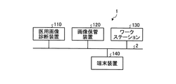
図1に示すように、第1の実施形態に係る画像処理システム1は、医用画像診断装置110と、画像保管装置120と、ワークステーション130と、端末装置140とを有する。図1に例示する各装置は、例えば、病院内に設置された院内LAN(Local Area Network)2により、直接的、又は間接的に相互に通信可能な状態となっている。例えば、画像処理システム1にPACS(Picture Archiving and Communication System)が導入されている場合、各装置は、DICOM(Digital Imaging and Communications in Medicine)規格に則って、医用画像等を相互に送受信する。
As shown in FIG. 1, the
かかる画像処理システム1は、医用画像診断装置110により生成された3次元の医用画像データであるボリュームデータから視差画像群を生成し、この視差画像群を立体視可能なモニタに表示することで、病院内に勤務する医師や検査技師等の観察者に対して、かかる観察者が立体的に視認可能な画像である立体画像を提供する。具体的には、第1の実施形態において、ワークステーション130は、ボリュームデータに対して種々の画像処理を行い、視差画像群を生成する。また、ワークステーション130及び端末装置140は、立体視可能なモニタを有し、ワークステーション130にて生成された視差画像群をモニタに表示することで立体画像を利用者に表示する。また、画像保管装置120は、医用画像診断装置110にて生成されたボリュームデータや、ワークステーション130にて生成された視差画像群を保管する。例えば、ワークステーション130や端末装置140は、画像保管装置120からボリュームデータや視差画像群を取得し、取得したボリュームデータや視差画像群に対して任意の画像処理を実行したり、視差画像群をモニタに表示したりする。以下、各装置を順に説明する。
The
医用画像診断装置110は、X線診断装置、X線CT(Computed Tomography)装置、MRI(Magnetic Resonance Imaging)装置、超音波診断装置、SPECT(Single Photon Emission Computed Tomography)装置、PET(Positron Emission computed Tomography)装置、SPECT装置とX線CT装置とが一体化されたSPECT−CT装置、PET装置とX線CT装置とが一体化されたPET−CT装置、又はこれらの装置群等である。また、第1の実施形態に係る医用画像診断装置110は、3次元の医用画像データ(ボリュームデータ)を生成可能である。
The medical image
具体的には、第1の実施形態に係る医用画像診断装置110は、被検体を撮影することによりボリュームデータを生成する。例えば、医用画像診断装置110は、被検体を撮影することにより投影データやMR信号等のデータを収集し、収集したデータから、被検体の体軸方向に沿った複数のアキシャル面の医用画像データを再構成することで、ボリュームデータを生成する。例えば、医用画像診断装置110は、500枚のアキシャル面の医用画像データを再構成する場合、この500枚のアキシャル面の医用画像データ群が、ボリュームデータとなる。なお、医用画像診断装置110により撮影された被検体の投影データやMR信号等自体をボリュームデータとしても良い。
Specifically, the medical image
また、第1の実施形態に係る医用画像診断装置110は、生成したボリュームデータを画像保管装置120に送信する。なお、医用画像診断装置110は、ボリュームデータを画像保管装置120に送信する際に、付帯情報として、例えば、患者を識別する患者ID、検査を識別する検査ID、医用画像診断装置110を識別する装置ID、医用画像診断装置110による1回の撮影を識別するシリーズID等を送信する。
Further, the medical image
画像保管装置120は、医用画像を保管するデータベースである。具体的には、第1の実施形態に係る画像保管装置120は、医用画像診断装置110からボリュームデータを受信し、受信したボリュームデータを所定の記憶部に保管する。また、第1の実施形態においては、ワークステーション130が、ボリュームデータから視差画像群を生成し、生成した視差画像群を画像保管装置120に送信する。このため、画像保管装置120は、ワークステーション130から送信された視差画像群を所定の記憶部に保管する。なお、本実施形態は、大容量の画像を保管可能なワークステーション130を用いることで、図1に例示するワークステーション130と画像保管装置120とが統合される場合であってもよい。すなわち、本実施形態は、ワークステーション130そのものにボリュームデータもしくは視差画像群を記憶させる場合であってもよい。
The image storage device 120 is a database that stores medical images. Specifically, the image storage device 120 according to the first embodiment receives volume data from the medical image
なお、第1の実施形態において、画像保管装置120に保管されたボリュームデータや視差画像群は、患者ID、検査ID、装置ID、シリーズID等と対応付けて保管される。このため、ワークステーション130や端末装置140は、患者ID、検査ID、装置ID、シリーズID等を用いた検索を行うことで、必要なボリュームデータや視差画像群を画像保管装置120から取得する。
In the first embodiment, the volume data and the parallax image group stored in the image storage device 120 are stored in association with the patient ID, examination ID, device ID, series ID, and the like. For this reason, the
ワークステーション130は、医用画像に対して画像処理を行う画像処理装置である。具体的には、第1の実施形態に係るワークステーション130は、画像保管装置120から取得したボリュームデータに対して種々のレンダリング処理を行うことで、視差画像群を生成する。
The
また、第1の実施形態に係るワークステーション130は、表示部として、立体画像を表示可能なモニタ(立体表示モニタ、立体画像表示装置とも称する)を有する。ワークステーション130は、視差画像群を生成し、生成した視差画像群を立体表示モニタに表示する。この結果、ワークステーション130の操作者は、立体表示モニタに表示された立体視可能な立体画像を確認しながら、視差画像群を生成するための操作を行うことができる。
Further, the
また、ワークステーション130は、生成した視差画像群を画像保管装置120や端末装置140に送信する。なお、ワークステーション130は、画像保管装置120や端末装置140に視差画像群を送信する際に、付帯情報として、例えば、患者ID、検査ID、装置ID、シリーズID等を送信する。視差画像群を画像保管装置120に送信する際に送信される付帯情報としては、視差画像群に関する付帯情報も挙げられる。視差画像群に関する付帯情報としては、視差画像の枚数(例えば、「9」)や、視差画像の解像度(例えば、「466×350画素」)等がある。
Further, the
端末装置140は、病院内に勤務する医師や検査技師に医用画像を閲覧させるための装置である。例えば、端末装置140は、病院内に勤務する医師や検査技師により操作されるPC(Personal Computer)やタブレット式PC、PDA(Personal Digital Assistant)、携帯電話等である。具体的には、第1の実施形態に係る端末装置140は、表示部として立体表示モニタを有する。また、端末装置140は、画像保管装置120やワークステーション130から視差画像群を取得し、取得した視差画像群を立体表示モニタに表示する。この結果、観察者である医師や検査技師は、立体視可能な医用画像を閲覧することができる。なお、端末装置140は、外部装置としての立体表示モニタと接続された任意の情報処理端末であってもよい。
The
ここで、ワークステーション130や端末装置140が有する立体表示モニタについて説明する。現在最も普及している一般的な汎用モニタは、2次元画像を2次元で表示するものであり、2次元画像を立体表示することができない。仮に、観察者が汎用モニタにて立体視を要望する場合、汎用モニタに対して画像を出力する装置は、平行法や交差法により観察者が立体視可能な2視差画像を並列表示させる必要がある。又は、汎用モニタに対して画像を出力する装置は、例えば、左目用の部分に赤色のセロハンが取り付けられ、右目用の部分に青色のセロハンが取り付けられたメガネを用いて余色法により観察者が立体視可能な画像を表示する必要がある。
Here, the stereoscopic display monitor included in the
一方、立体表示モニタとしては、立体視用メガネ等の専用機器を用いることで、2視差画像(両眼視差画像とも称する)を立体視可能とするものがある。 On the other hand, as a stereoscopic display monitor, there is a stereoscopic display monitor that enables a stereoscopic view of a two-parallax image (also referred to as a binocular parallax image) by using dedicated equipment such as stereoscopic glasses.
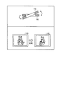
図2は、2視差画像により立体表示を行う立体表示モニタの一例を説明するための図である。図2に示す一例は、シャッター方式により立体表示を行う立体表示モニタであり、モニタを観察する観察者が装着する立体視用メガネとしてシャッターメガネが用いられる。かかる立体表示モニタは、モニタにて2視差画像を交互に出射する。例えば、図2の(A)に示すモニタは、左目用の画像と右目用の画像を、120Hzにて交互に出射する。ここで、モニタには、図2の(A)に示すように、赤外線出射部が設置され、赤外線出射部は、画像が切り替わるタイミングに合わせて赤外線の出射を制御する。 FIG. 2 is a diagram for explaining an example of a stereoscopic display monitor that performs stereoscopic display using two parallax images. An example shown in FIG. 2 is a stereoscopic display monitor that performs stereoscopic display by a shutter method, and shutter glasses are used as stereoscopic glasses worn by an observer who observes the monitor. Such a stereoscopic display monitor emits two parallax images alternately on the monitor. For example, the monitor shown in FIG. 2A alternately emits a left-eye image and a right-eye image at 120 Hz. Here, as shown in FIG. 2A, the monitor is provided with an infrared emitting unit, and the infrared emitting unit controls the emission of infrared rays in accordance with the timing at which the image is switched.
また、赤外線出射部から出射された赤外線は、図2の(A)に示すシャッターメガネの赤外線受光部により受光される。シャッターメガネの左右それぞれの枠には、シャッターが取り付けられており、シャッターメガネは、赤外線受光部が赤外線を受光したタイミングに合わせて左右のシャッターそれぞれの透過状態及び遮光状態を交互に切り替える。以下、シャッターにおける透過状態及び遮光状態の切り替え処理について説明する。 Moreover, the infrared rays emitted from the infrared ray emitting portion are received by the infrared ray receiving portion of the shutter glasses shown in FIG. A shutter is attached to each of the left and right frames of the shutter glasses, and the shutter glasses alternately switch the transmission state and the light shielding state of the left and right shutters according to the timing when the infrared light receiving unit receives the infrared rays. Hereinafter, the switching process between the transmission state and the light shielding state in the shutter will be described.
各シャッターは、図2の(B)に示すように、入射側の偏光板と出射側の偏光板とを有し、更に、入射側の偏光板と出射側の偏光板との間に液晶層を有する。また、入射側の偏光板と出射側の偏光板とは、図2の(B)に示すように、互いに直交している。ここで、図2の(B)に示すように、電圧が印加されていない「OFF」の状態では、入射側の偏光板を通った光は、液晶層の作用により90度回転し、出射側の偏光板を透過する。すなわち、電圧が印加されていないシャッターは、透過状態となる。 As shown in FIG. 2B, each shutter has an incident-side polarizing plate and an output-side polarizing plate, and a liquid crystal layer between the incident-side polarizing plate and the output-side polarizing plate. Have Further, as shown in FIG. 2B, the incident-side polarizing plate and the outgoing-side polarizing plate are orthogonal to each other. Here, as shown in FIG. 2B, in the “OFF” state where no voltage is applied, the light that has passed through the polarizing plate on the incident side is rotated by 90 ° by the action of the liquid crystal layer, and is emitted on the outgoing side. Is transmitted through the polarizing plate. That is, a shutter to which no voltage is applied is in a transmissive state.
一方、図2の(B)に示すように、電圧が印加された「ON」の状態では、液晶層の液晶分子による偏光回転作用が消失するため、入射側の偏光板を通った光は、出射側の偏光板で遮られてしまう。すなわち、電圧が印加されたシャッターは、遮光状態となる。 On the other hand, as shown in FIG. 2B, in the “ON” state where a voltage is applied, the polarization rotation action caused by the liquid crystal molecules in the liquid crystal layer disappears. It will be blocked by the polarizing plate on the exit side. That is, the shutter to which the voltage is applied is in a light shielding state.
そこで、例えば、赤外線出射部は、モニタ上に左目用の画像が表示されている期間、赤外線を出射する。そして、赤外線受光部は、赤外線を受光している期間、左目のシャッターに電圧を印加せず、右目のシャッターに電圧を印加させる。これにより、図2の(A)に示すように、右目のシャッターが遮光状態となり、左目のシャッターが透過状態となるため、観察者の左目に左目用の画像が入射する。一方、赤外線出射部は、モニタ上に右目用の画像が表示されている期間、赤外線の出射を停止する。そして、赤外線受光部は、赤外線が受光されない期間、右目のシャッターに電圧を印加せず、左目のシャッターに電圧を印加させる。これにより、左目のシャッターが遮光状態となり、右目のシャッターが透過状態であるため、観察者の右目に右目用の画像が入射する。このように、図2に示す立体表示モニタは、モニタに表示される画像とシャッターの状態を連動させて切り替えることで、観察者が立体視可能な画像を表示させる。なお、2視差画像を立体視可能な立体表示モニタとしては、上記のシャッター方式以外にも、偏光メガネ方式を採用したモニタも知られている。 Therefore, for example, the infrared emitting unit emits infrared rays during a period in which an image for the left eye is displayed on the monitor. The infrared light receiving unit applies a voltage to the right-eye shutter without applying a voltage to the left-eye shutter during a period of receiving the infrared light. Accordingly, as shown in FIG. 2A, the right-eye shutter is in a light-shielding state and the left-eye shutter is in a transmissive state, so that an image for the left eye is incident on the left eye of the observer. On the other hand, the infrared ray emitting unit stops emitting infrared rays while the right-eye image is displayed on the monitor. The infrared light receiving unit applies a voltage to the left-eye shutter without applying a voltage to the right-eye shutter during a period in which no infrared light is received. Accordingly, the left-eye shutter is in a light-shielding state and the right-eye shutter is in a transmissive state, so that an image for the right eye is incident on the right eye of the observer. As described above, the stereoscopic display monitor illustrated in FIG. 2 displays an image that can be viewed stereoscopically by the observer by switching the image displayed on the monitor and the state of the shutter in conjunction with each other. As a stereoscopic display monitor capable of stereoscopically viewing a two-parallax image, a monitor adopting a polarized glasses method is also known in addition to the shutter method described above.
更に、近年実用化された立体表示モニタとしては、レンチキュラーレンズ等の光線制御子を用いることで、例えば、9視差画像等の多視差画像を観察者が裸眼にて立体視可能とするものがある。かかる立体表示モニタは、両眼視差による立体視を可能とし、更に、観察者の視点移動に合わせて観察される映像も変化する運動視差による立体視も可能とする。 Furthermore, as a stereoscopic display monitor that has been put into practical use in recent years, there is a stereoscopic display monitor that allows a viewer to stereoscopically view a multi-parallax image such as a 9-parallax image with the naked eye by using a light controller such as a lenticular lens. . Such a stereoscopic display monitor enables stereoscopic viewing based on binocular parallax, and also enables stereoscopic viewing based on motion parallax that also changes the image observed in accordance with the viewpoint movement of the observer.
図3は、9視差画像により立体表示を行う立体表示モニタの一例を説明するための図である。図3に示す立体表示モニタには、液晶パネル等の平面状の表示面200の前面に、光線制御子が配置される。例えば、図3に示す立体表示モニタには、光線制御子として、光学開口が垂直方向に延びる垂直レンチキュラーシート201が表示面200の前面に貼り付けられている。なお、図3に示す一例では、垂直レンチキュラーシート201の凸部が前面となるように貼り付けられているが、垂直レンチキュラーシート201の凸部が表示面200に対向するように貼り付けられる場合であってもよい。
FIG. 3 is a diagram for explaining an example of a stereoscopic display monitor that performs stereoscopic display with nine parallax images. In the stereoscopic display monitor shown in FIG. 3, a light beam controller is arranged on the front surface of a
表示面200には、図3に示すように、縦横比が3:1であり、縦方向にサブ画素である赤(R)、緑(G)、青(B)の3つが配置された画素202がマトリクス状に配置される。図3に示す立体表示モニタは、9つの画像により構成される9視差画像を、所定フォーマット(例えば格子状)に配置した中間画像に変換したうえで、表示面200に出力する。すなわち、図3に示す立体表示モニタは、9視差画像にて同一位置にある9つの画素それぞれを、9列の画素202に割り振って出力させる。9列の画素202は、視点位置の異なる9つの画像を同時に表示する単位画素群203となる。
As shown in FIG. 3, the
表示面200において単位画素群203として同時に出力された9視差画像は、例えば、LED(Light Emitting Diode)バックライトにより平行光として放射され、更に、垂直レンチキュラーシート201により、多方向に放射される。9視差画像の各画素の光が多方向に放射されることにより、観察者の右目及び左目に入射する光は、観察者の位置(視点の位置)に連動して変化する。すなわち、観察者の見る角度により、右目に入射する視差画像と左目に入射する視差画像とは、視差角が異なる。これにより、観察者は、例えば、図3に示す9つの位置それぞれにおいて、撮影対象を立体的に視認できる。また、観察者は、例えば、図3に示す「5」の位置において、撮影対象に対して正対した状態で立体的に視認できるとともに、図3に示す「5」以外それぞれの位置において、撮影対象の向きを変化させた状態で立体的に視認できる。なお、図3に示す立体表示モニタは、あくまでも一例である。9視差画像を表示する立体表示モニタは、図3に示すように、「RRR・・・、GGG・・・、BBB・・・」の横ストライプ液晶である場合であってもよいし、「RGBRGB・・・」の縦ストライプ液晶である場合であってもよい。また、図3に示す立体表示モニタは、図3に示すように、レンチキュラーシートが垂直となる縦レンズ方式である場合であってもよいし、レンチキュラーシートが斜めとなる斜めレンズ方式である場合であってもよい。
The nine parallax images simultaneously output as the
ここまで、第1の実施形態に係る画像処理システム1の構成例について簡単に説明した。なお、上述した画像処理システム1は、PACSが導入されている場合にその適用が限られるものではない。例えば、画像処理システム1は、医用画像が添付された電子カルテを管理する電子カルテシステムが導入されている場合にも、同様に適用される。この場合、画像保管装置120は、電子カルテを保管するデータベースである。また、例えば、画像処理システム1は、HIS(Hospital Information System)、RIS(Radiology Information System)が導入されている場合にも、同様に適用される。また、画像処理システム1は、上述した構成例に限られるものではない。各装置が有する機能やその分担は、運用の形態に応じて適宜変更されてよい。
So far, the configuration example of the
次に、第1の実施形態に係るワークステーションの構成例について図4を用いて説明する。図4は、第1の実施形態に係るワークステーションの構成例を説明するための図である。なお、以下において、「視差画像群」とは、ボリュームデータに対してボリュームレンダリング処理を行うことで生成された立体視用の画像群のことである。また、「視差画像」とは、「視差画像群」を構成する個々の画像のことである。すなわち、「視差画像群」は、視点位置が異なる複数の「視差画像」から構成される。 Next, a configuration example of the workstation according to the first embodiment will be described with reference to FIG. FIG. 4 is a diagram for explaining a configuration example of the workstation according to the first embodiment. In the following description, the “parallax image group” refers to a group of stereoscopic images generated by performing volume rendering processing on volume data. Further, the “parallax image” is an individual image constituting the “parallax image group”. That is, the “parallax image group” includes a plurality of “parallax images” having different viewpoint positions.
第1の実施形態に係るワークステーション130は、画像処理等に適した高性能なコンピュータであり、図4に示すように、入力部131と、表示部132と、通信部133と、記憶部134と、制御部135と、レンダリング処理部136とを有する。なお、以下では、ワークステーション130が画像処理等に適した高性能なコンピュータである場合を用いて説明するが、これに限定されるものではなく、任意の情報処理装置であってよい。例えば、任意のパーソナルコンピュータであってもよい。
The
入力部131は、マウス、キーボード、トラックボール等であり、ワークステーション130に対する各種操作の入力を操作者から受け付ける。具体的には、第1の実施形態に係る入力部131は、レンダリング処理の対象となるボリュームデータを画像保管装置120から取得するための情報の入力を受け付ける。例えば、入力部131は、患者ID、検査ID、装置ID、シリーズID等の入力を受け付ける。また、第1の実施形態に係る入力部131は、レンダリング処理に関する条件(以下、レンダリング条件)の入力を受け付ける。
The input unit 131 is a mouse, a keyboard, a trackball, or the like, and receives input of various operations on the
表示部132は、立体表示モニタとしての液晶パネル等であり、各種情報を表示する。具体的には、第1の実施形態に係る表示部132は、操作者から各種操作を受け付けるためのGUI(Graphical User Interface)や、視差画像群等を表示する。通信部133は、NIC(Network Interface Card)等であり、他の装置との間で通信を行う。
The
記憶部134は、ハードディスク、半導体メモリ素子等であり、各種情報を記憶する。具体的には、第1の実施形態に係る記憶部134は、通信部133を介して画像保管装置120から取得したボリュームデータを記憶する。また、第1の実施形態に係る記憶部134は、レンダリング処理中のボリュームデータや、レンダリング処理により生成された視差画像群等を記憶する。
The storage unit 134 is a hard disk, a semiconductor memory element, or the like, and stores various types of information. Specifically, the storage unit 134 according to the first embodiment stores volume data acquired from the image storage device 120 via the
制御部135は、CPU(Central Processing Unit)、MPU(Micro Processing Unit)やGPU(Graphics Processing Unit)等の電子回路、ASIC(Application Specific Integrated Circuit)やFPGA(Field Programmable Gate Array)等の集積回路であり、ワークステーション130の全体制御を行う。
The control unit 135 is an electronic circuit such as a CPU (Central Processing Unit), MPU (Micro Processing Unit) or GPU (Graphics Processing Unit), or an integrated circuit such as ASIC (Application Specific Integrated Circuit) or FPGA (Field Programmable Gate Array). Yes, the entire control of the
例えば、第1の実施形態に係る制御部135は、表示部132に対するGUIの表示や視差画像群の表示を制御する。また、例えば、制御部135は、画像保管装置120との間で通信部133を介して行われるボリュームデータや視差画像群の送受信を制御する。また、例えば、制御部135は、レンダリング処理部136によるレンダリング処理を制御する。また、例えば、制御部135は、ボリュームデータの記憶部134からの読み込みや、視差画像群の記憶部134への格納を制御する。
For example, the control unit 135 according to the first embodiment controls the display of the GUI and the display of the parallax image group on the
レンダリング処理部136は、制御部135による制御の下、画像保管装置120から取得したボリュームデータに対して種々のレンダリング処理を行い、視差画像群を生成する。具体的には、第1の実施形態に係るレンダリング処理部136は、記憶部134からボリュームデータを読み込み、このボリュームデータに対して、まず前処理を行う。次に、レンダリング処理部136は、前処理後のボリュームデータに対してボリュームレンダリング処理を行い、視差画像群を生成する。続いて、レンダリング処理部136は、各種情報(目盛り、患者名、検査項目等)が描出された2次元画像を生成し、これを視差画像群それぞれに対して重畳することで、出力用の2次元画像を生成する。そして、レンダリング処理部136は、生成した視差画像群や出力用の2次元画像を記憶部134に格納する。なお、第1の実施形態において、レンダリング処理とは、ボリュームデータに対して行う画像処理全体のことであり、ボリュームレンダリング処理とは、レンダリング処理の内、3次元の情報を反映した2次元画像を生成する処理のことである。レンダリング処理により生成される医用画像とは、例えば、視差画像が該当する。
The
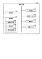
図5は、図4に示すレンダリング処理部の構成例を説明するための図である。図5に示すように、レンダリング処理部136は、前処理部1361と、3次元画像処理部1362と、2次元画像処理部1363とを有する。前処理部1361が、ボリュームデータに対する前処理を行い、3次元画像処理部1362が、前処理後のボリュームデータから視差画像群を生成し、2次元画像処理部1363が、視差画像群に各種情報が重畳された出力用の2次元画像を生成する。以下、各部を順に説明する。
FIG. 5 is a diagram for explaining a configuration example of the rendering processing unit shown in FIG. As illustrated in FIG. 5, the
前処理部1361は、ボリュームデータに対してレンダリング処理を行う際に、種々の前処理を行う処理部であり、画像補正処理部1361aと、3次元物体フュージョン部1361eと、3次元物体表示領域設定部1361fとを有する。
The preprocessing unit 1361 is a processing unit that performs various types of preprocessing when rendering processing is performed on volume data, and includes an image correction processing unit 1361a, a three-dimensional
画像補正処理部1361aは、2種類のボリュームデータを1つのボリュームデータとして処理する際に画像補正処理を行う処理部であり、図5に示すように、歪み補正処理部1361b、体動補正処理部1361c及び画像間位置合わせ処理部1361dを有する。例えば、画像補正処理部1361aは、PET−CT装置により生成されたPET画像のボリュームデータとX線CT画像のボリュームデータとを1つのボリュームデータとして処理する際に画像補正処理を行う。或いは、画像補正処理部1361aは、MRI装置により生成されたT1強調画像のボリュームデータとT2強調画像のボリュームデータとを1つのボリュームデータとして処理する際に画像補正処理を行う。
The image correction processing unit 1361a is a processing unit that performs image correction processing when processing two types of volume data as one volume data, and as illustrated in FIG. 5, a distortion
また、歪み補正処理部1361bは、個々のボリュームデータにおいて、医用画像診断装置110によるデータ収集時の収集条件に起因するデータの歪みを補正する。また、体動補正処理部1361cは、個々のボリュームデータを生成するために用いられたデータの収集時期における被検体の体動に起因する移動を補正する。また、画像間位置合わせ処理部1361dは、歪み補正処理部1361b及び体動補正処理部1361cによる補正処理が行われた2つのボリュームデータ間で、例えば、相互相関法等を用いた位置合わせ(Registration)を行う。
In addition, the distortion
3次元物体フュージョン部1361eは、画像間位置合わせ処理部1361dにより位置合わせが行われた複数のボリュームデータをフュージョンさせる。なお、画像補正処理部1361a及び3次元物体フュージョン部1361eの処理は、単一のボリュームデータに対してレンダリング処理を行う場合、省略される。
The three-dimensional
3次元物体表示領域設定部1361fは、操作者により指定された表示対象臓器に対応する表示領域を設定する処理部であり、セグメンテーション処理部1361gを有する。セグメンテーション処理部1361gは、操作者により指定された心臓、肺、血管等の臓器を、例えば、ボリュームデータの画素値(ボクセル値)に基づく領域拡張法により抽出する処理部である。
The three-dimensional object display
なお、セグメンテーション処理部1361gは、操作者により表示対象臓器が指定されなかった場合、セグメンテーション処理を行わない。また、セグメンテーション処理部1361gは、操作者により表示対象臓器が複数指定された場合、該当する複数の臓器を抽出する。また、セグメンテーション処理部1361gの処理は、レンダリング画像を参照した操作者の微調整要求により再度実行される場合もある。 Note that the segmentation processing unit 1361g does not perform the segmentation process when the display target organ is not designated by the operator. The segmentation processing unit 1361g extracts a plurality of corresponding organs when a plurality of display target organs are designated by the operator. Further, the processing of the segmentation processing unit 1361g may be executed again in response to an operator fine adjustment request referring to the rendered image.
3次元画像処理部1362は、前処理部1361が処理を行った前処理後のボリュームデータに対してボリュームレンダリング処理を行う。ボリュームレンダリング処理を行う処理部として、3次元画像処理部1362は、投影方法設定部1362aと、3次元幾何変換処理部1362bと、3次元物体アピアランス処理部1362fと、3次元仮想空間レンダリング部1362kとを有する。
The three-dimensional
投影方法設定部1362aは、視差画像群を生成するための投影方法を決定する。例えば、投影方法設定部1362aは、ボリュームレンダリング処理を平行投影法により実行するか、透視投影法により実行するかを決定する。 The projection method setting unit 1362a determines a projection method for generating a parallax image group. For example, the projection method setting unit 1362a determines whether to execute the volume rendering process by the parallel projection method or the perspective projection method.
3次元幾何変換処理部1362bは、ボリュームレンダリング処理が実行されるボリュームデータを3次元幾何学的に変換するための情報を決定する処理部であり、平行移動処理部1362c、回転処理部1362d及び拡大縮小処理部1362eを有する。平行移動処理部1362cは、ボリュームレンダリング処理を行う際の視点位置が平行移動された場合に、ボリュームデータを平行移動させる移動量を決定する処理部であり、回転処理部1362dは、ボリュームレンダリング処理を行う際の視点位置が回転移動された場合に、ボリュームデータを回転移動させる移動量を決定する処理部である。また、拡大縮小処理部1362eは、視差画像群の拡大や縮小が要求された場合に、ボリュームデータの拡大率や縮小率を決定する処理部である。
The three-dimensional geometric
3次元物体アピアランス処理部1362fは、3次元物体色彩処理部1362g、3次元物体不透明度処理部1362h、3次元物体材質処理部1362i及び3次元仮想空間光源処理部1362jを有する。3次元物体アピアランス処理部1362fは、これらの処理部により、例えば、操作者の要求に応じて、表示される視差画像群の表示状態を決定する処理を行う。
The three-dimensional object
3次元物体色彩処理部1362gは、ボリュームデータにてセグメンテーションされた各領域に対して着色される色彩を決定する処理部である。3次元物体不透明度処理部1362hは、ボリュームデータにてセグメンテーションされた各領域を構成する各ボクセルの不透過度(Opacity)を決定する処理部である。なお、ボリュームデータにおいて不透過度が「100%」とされた領域の後方の領域は、視差画像群において描出されないこととなる。また、ボリュームデータにおいて不透過度が「0%」とされた領域は、視差画像群において描出されないこととなる。 The three-dimensional object color processing unit 1362g is a processing unit that determines a color to be colored for each region segmented by the volume data. The three-dimensional object opacity processing unit 1362h is a processing unit that determines the opacity (Opacity) of each voxel constituting each region segmented by volume data. It should be noted that the area behind the area having the opacity of “100%” in the volume data is not drawn in the parallax image group. In addition, an area in which the opacity is “0%” in the volume data is not drawn in the parallax image group.
3次元物体材質処理部1362iは、ボリュームデータにてセグメンテーションされた各領域の材質を決定することで、この領域が描出される際の質感を調整する処理部である。3次元仮想空間光源処理部1362jは、ボリュームデータに対してボリュームレンダリング処理を行う際に、3次元仮想空間に設置する仮想光源の位置や、仮想光源の種類を決定する処理部である。仮想光源の種類としては、無限遠から平行な光線を照射する光源や、視点から放射状の光線を照射する光源等が挙げられる。
The three-dimensional object
3次元仮想空間レンダリング部1362kは、ボリュームデータに対してボリュームレンダリング処理を行い、視差画像群を生成する。また、3次元仮想空間レンダリング部1362kは、ボリュームレンダリング処理を行う際、必要に応じて、投影方法設定部1362a、3次元幾何変換処理部1362b、3次元物体アピアランス処理部1362fにより決定された各種情報を用いる。
The three-dimensional virtual space rendering unit 1362k performs volume rendering processing on the volume data to generate a parallax image group. The three-dimensional virtual space rendering unit 1362k performs various types of information determined by the projection method setting unit 1362a, the three-dimensional geometric
ここで、3次元仮想空間レンダリング部1362kによるボリュームレンダリング処理は、レンダリング条件に従って行われることになる。例えば、レンダリング条件は、「平行投影法」又は「透視投影法」である。また、例えば、レンダリング条件は、「基準の視点位置、視差角及び視差数」である。また、例えば、レンダリング条件は、「視点位置の平行移動」、「視点位置の回転移動」、「視差画像群の拡大」、「視差画像群の縮小」である。また、例えば、レンダリング条件は、「着色される色彩」、「透過度」、「質感」、「仮想光源の位置」、「仮想光源の種類」である。このようなレンダリング条件は、入力部131を介して操作者から受け付ける場合や、初期設定される場合が考えられる。いずれの場合も、3次元仮想空間レンダリング部1362kは、制御部135からレンダリング条件を受け付け、このレンダリング条件に従って、ボリュームデータに対するボリュームレンダリング処理を行う。また、このとき、上述した投影方法設定部1362a、3次元幾何変換処理部1362b、3次元物体アピアランス処理部1362fが、このレンダリング条件に従って必要な各種情報を決定するので、3次元仮想空間レンダリング部1362kは、決定されたこれらの各種情報を用いて視差画像群を生成する。
Here, the volume rendering process by the three-dimensional virtual space rendering unit 1362k is performed according to the rendering conditions. For example, the rendering condition is “parallel projection method” or “perspective projection method”. For example, the rendering condition is “reference viewpoint position, parallax angle, and number of parallaxes”. Further, for example, the rendering conditions are “translation of viewpoint position”, “rotational movement of viewpoint position”, “enlargement of parallax image group”, and “reduction of parallax image group”. Further, for example, the rendering conditions are “color to be colored”, “transparency”, “texture”, “position of virtual light source”, and “type of virtual light source”. Such a rendering condition may be accepted from the operator via the input unit 131 or may be initially set. In any case, the three-dimensional virtual space rendering unit 1362k receives a rendering condition from the control unit 135, and performs volume rendering processing on the volume data according to the rendering condition. At this time, the projection method setting unit 1362a, the three-dimensional geometric
図6は、第1の実施形態に係るボリュームレンダリング処理の一例を説明するための図である。例えば、3次元仮想空間レンダリング部1362kが、図6の「9視差画像生成方式(1)」に示すように、レンダリング条件として、平行投影法を受け付け、更に、基準の視点位置(5)と視差角「1度」とを受け付けたとする。かかる場合、3次元仮想空間レンダリング部1362kは、視差角が「1度」おきとなるように、視点の位置を(1)〜(9)に平行移動して、平行投影法により視差角(視線方向間の角度)が1度ずつ異なる9つの視差画像を生成する。なお、平行投影法を行う場合、3次元仮想空間レンダリング部1362kは、視線方向に沿って無限遠から平行な光線を照射する光源を設定する。 FIG. 6 is a diagram for explaining an example of volume rendering processing according to the first embodiment. For example, as shown in “9 parallax image generation method (1)” in FIG. 6, the three-dimensional virtual space rendering unit 1362k accepts the parallel projection method as a rendering condition, and further, the reference viewpoint position (5) and the parallax. Assume that the angle “1 degree” is received. In such a case, the three-dimensional virtual space rendering unit 1362k translates the position of the viewpoint from (1) to (9) so that the parallax angle is "1 degree", and the parallax angle (line of sight) is obtained by the parallel projection method. Nine parallax images with different degrees between directions are generated. When performing parallel projection, the three-dimensional virtual space rendering unit 1362k sets a light source that emits parallel light rays from infinity along the line-of-sight direction.
或いは、3次元仮想空間レンダリング部1362kが、図6の「9視差画像生成方式(2)」に示すように、レンダリング条件として、透視投影法を受け付け、更に、基準の視点位置(5)と視差角「1度」とを受け付けたとする。かかる場合、3次元仮想空間レンダリング部1362kは、ボリュームデータの中心(重心)を中心に視差角が「1度」おきとなるように、視点の位置を(1)〜(9)に回転移動して、透視投影法により視差角が1度ずつ異なる9つの視差画像を生成する。なお、透視投影法を行う場合、3次元仮想空間レンダリング部1362kは、視線方向を中心に光を3次元的に放射状に照射する点光源や面光源を各視点にて設定する。また、透視投影法を行う場合、レンダリング条件によっては、視点(1)〜(9)は、平行移動される場合であってもよい。 Alternatively, as shown in “9-parallax image generation method (2)” in FIG. 6, the three-dimensional virtual space rendering unit 1362k accepts a perspective projection method as a rendering condition, and further, the reference viewpoint position (5) and the parallax Assume that the angle “1 degree” is received. In such a case, the three-dimensional virtual space rendering unit 1362k rotates and moves the viewpoint position from (1) to (9) so that the parallax angle is every "1 degree" around the center (center of gravity) of the volume data. Thus, nine parallax images having different parallax angles by 1 degree are generated by the perspective projection method. When performing the perspective projection method, the three-dimensional virtual space rendering unit 1362k sets a point light source or a surface light source that radiates light three-dimensionally radially around the viewing direction at each viewpoint. Further, when the perspective projection method is performed, the viewpoints (1) to (9) may be translated depending on the rendering condition.
なお、3次元仮想空間レンダリング部1362kは、表示されるボリュームレンダリング画像の縦方向に対しては、視線方向を中心に光を2次元的に放射状に照射し、表示されるボリュームレンダリング画像の横方向に対しては、視線方向に沿って無限遠から平行な光線を照射する光源を設定することで、平行投影法と透視投影法とを併用したボリュームレンダリング処理を行ってもよい。 Note that the three-dimensional virtual space rendering unit 1362k radiates light two-dimensionally radially around the line-of-sight direction with respect to the vertical direction of the displayed volume rendered image, and the horizontal direction of the displayed volume rendered image. On the other hand, volume rendering processing using both the parallel projection method and the perspective projection method may be performed by setting a light source that irradiates parallel light rays from infinity along the line-of-sight direction.
このようにして生成された9つの視差画像が、視差画像群である。第1の実施形態において、9つの視差画像は、例えば制御部135により所定フォーマット(例えば格子状)に配置した中間画像に変換され、立体表示モニタとしての表示部132に出力される。すると、ワークステーション130の操作者は、立体表示モニタに表示された立体視可能な医用画像を確認しながら、視差画像群生成のための操作を行うことができる。
The nine parallax images generated in this way are a parallax image group. In the first embodiment, the nine parallax images are converted into intermediate images arranged in a predetermined format (for example, a lattice shape) by the control unit 135, for example, and are output to the
なお、図6の例では、レンダリング条件として、投影方法、基準の視点位置及び視差角を受け付けた場合を説明したが、レンダリング条件として、他の条件を受け付けた場合も同様に、3次元仮想空間レンダリング部1362kは、それぞれのレンダリング条件を反映しつつ、視差画像群を生成する。 In the example of FIG. 6, the case where the projection method, the reference viewpoint position, and the parallax angle are received as the rendering conditions has been described. However, the three-dimensional virtual space is similarly applied when other conditions are received as the rendering conditions. The rendering unit 1362k generates a parallax image group while reflecting each rendering condition.
また、3次元仮想空間レンダリング部1362kは、ボリュームレンダリングだけでなく、断面再構成法(MPR:Multi Planer Reconstruction)を行ってボリュームデータからMPR画像を再構成する機能も有する。なお、3次元仮想空間レンダリング部1362kは、「Curved MPR」を行う機能や、「Intensity Projection」を行う機能も有する。 The three-dimensional virtual space rendering unit 1362k has not only volume rendering but also a function of reconstructing an MPR image from volume data by performing a cross-section reconstruction method (MPR: Multi Planer Reconstruction). The three-dimensional virtual space rendering unit 1362k also has a function of performing “Curved MPR” and a function of performing “Intensity Projection”.
続いて、3次元画像処理部1362がボリュームデータから生成した視差画像群は、アンダーレイ(Underlay)とされる。そして、各種情報(目盛り、患者名、検査項目等)が描出されたオーバーレイ(Overlay)がアンダーレイに対して重畳されることで、出力用の2次元画像とされる。2次元画像処理部1363は、オーバーレイ及びアンダーレイに対して画像処理を行うことで、出力用の2次元画像を生成する処理部であり、図5に示すように、2次元物体描画部1363a、2次元幾何変換処理部1363b及び輝度調整部1363cを有する。例えば、2次元画像処理部1363は、出力用の2次元画像の生成処理に要する負荷を軽減するために、9枚の視差画像(アンダーレイ)のそれぞれに対して1枚のオーバーレイを重畳することで、出力用の2次元画像を9枚、生成する。なお、以下では、オーバーレイが重畳されたアンダーレイを単に「視差画像」と表記する場合もある。
Subsequently, the parallax image group generated from the volume data by the three-dimensional
2次元物体描画部1363aは、オーバーレイに描出される各種情報を描画する処理部であり、2次元幾何変換処理部1363bは、オーバーレイに描出される各種情報の位置を平行移動処理又は回転移動処理したり、オーバーレイに描出される各種情報の拡大処理又は縮小処理したりする処理部である。 The two-dimensional object drawing unit 1363a is a processing unit that draws various information drawn on the overlay, and the two-dimensional geometric transformation processing unit 1363b performs parallel movement processing or rotational movement processing on the position of the various information drawn on the overlay. Or a processing unit that performs an enlargement process or a reduction process of various types of information drawn on the overlay.
また、輝度調整部1363cは、輝度変換処理を行う処理部であり、例えば、出力先の立体表示モニタの諧調や、ウィンドウ幅(WW:Window Width)、ウィンドウレベル(WL:Window Level)等の画像処理用のパラメータに応じて、オーバーレイ及びアンダーレイの輝度を調整する処理部である。
The
制御部135は、例えば、このようにして生成された出力用の2次元画像を、一旦記憶部134に格納し、その後、通信部133を介して画像保管装置120に送信する。そして、端末装置140は、例えば、画像保管装置120からこの出力用の2次元画像を取得し、所定フォーマット(例えば格子状)に配置した中間画像に変換した上で立体表示モニタに表示する。また、例えば、制御部135は、出力用の2次元画像を、一旦記憶部134に格納し、その後、通信部133を介して画像保管装置120に送信するとともに、端末装置140に送信する。そして、端末装置140は、ワークステーション130から受信した出力用の2次元画像を所定フォーマット(例えば格子状)に配置した中間画像に変換した上で立体表示モニタに表示する。これにより、端末装置140を利用する医師や検査技師は、各種情報(目盛り、患者名、検査項目等)が描出された状態で、立体視可能な医用画像を閲覧することができる。
For example, the control unit 135 temporarily stores the output two-dimensional image generated in this manner in the storage unit 134 and then transmits the two-dimensional image to the image storage device 120 via the
ところで、第1の実施形態における端末装置140は、タブレット式PC、PDA又は携帯電話等の持ち運び可能な端末であり、被検体にかざされた場合に、かざされた位置に対応する部位(臓器等)の視差画像群を表示することで、かかる臓器等の立体画像を利用者に提供する。この点について、図7を用いて簡単に説明する。図7は、第1の実施形態における端末装置140によって表示される立体画像の一例を示す図である。
By the way, the
図7では、端末装置140は、利用者によって被検体Pの胸部にかざされた例を示している。かかる場合に、端末装置140は、被検体Pの胸部に位置する臓器として心臓の立体画像を立体表示モニタに表示する。これにより、利用者は、端末装置140を被検体Pにかざさすだけで、かざした位置に対応する部位の立体画像を観察することができる。以下に、このような第1の実施形態における端末装置140について詳細に説明する。
FIG. 7 shows an example in which the
図8は、第1の実施形態における端末装置140の構成例を説明するための図である。図8に示した端末装置140は、タブレット式PC等の持ち運び可能な端末であり、利用者によって所定の操作が行われた場合に、かかる操作に応じた立体画像を表示する。図8に例示するように、第1の実施形態における端末装置140は、入力部141と、立体表示モニタ142と、通信部143と、記憶部144と、位置センサ145と、制御部146とを有する。
FIG. 8 is a diagram for describing a configuration example of the
入力部141は、端末装置140に設けられた所定のキー等であり、端末装置140に対する各種操作の入力を操作者から受け付ける。例えば、入力部141は、立体視要求として、操作者が立体視を要望するボリュームデータを指定するための患者ID、検査ID、装置ID、シリーズID等の入力を受け付ける。
The input unit 141 is a predetermined key or the like provided on the
立体表示モニタ142は、立体表示モニタとしての液晶パネル等であり、各種情報を表示する。具体的には、第1の実施形態に係る立体表示モニタ142は、操作者から各種操作を受け付けるためのGUI(Graphical User Interface)や、視差画像群等を表示する。例えば、立体表示モニタ142は、図2を用いて説明した立体表示モニタ(以下、2視差モニタと記載する)や、図6を用いて説明した立体表示モニタ(以下、9視差モニタと記載する)である。以下では、立体表示モニタ142が9視差モニタである場合について説明する。 The stereoscopic display monitor 142 is a liquid crystal panel or the like as a stereoscopic display monitor, and displays various types of information. Specifically, the stereoscopic display monitor 142 according to the first embodiment displays a GUI (Graphical User Interface) for receiving various operations from the operator, a parallax image group, and the like. For example, the stereoscopic display monitor 142 may be the stereoscopic display monitor described with reference to FIG. 2 (hereinafter referred to as “2 parallax monitor”) or the stereoscopic display monitor described with reference to FIG. 6 (hereinafter referred to as “9 parallax monitor”). It is. Hereinafter, a case where the stereoscopic display monitor 142 is a nine-parallax monitor will be described.
なお、第1の実施形態における端末装置140は、タブレット式PC等の持ち運び可能な端末であるので、入力部141と立体表示モニタ142とが一体化されたタッチパネル式の表示部を有してもよい。
Since the
通信部143は、NIC(Network Interface Card)等であり、他の装置との間で通信を行う。具体的には、第1の実施形態に係る通信部143は、入力部141が受け付けた立体視要求をワークステーション130に送信する。また、第1の実施形態に係る通信部143は、立体視要求に応じてワークステーション130が送信した視差画像群を受信する。
The communication unit 143 is a NIC (Network Interface Card) or the like, and performs communication with other devices. Specifically, the communication unit 143 according to the first embodiment transmits the stereoscopic request received by the input unit 141 to the
記憶部144は、ハードディスク、半導体メモリ素子等であり、各種情報を記憶する。具体的には、記憶部144は、通信部143を介してワークステーション130から取得した視差画像群を記憶する。また、記憶部144は、通信部143を介してワークステーション130から取得した視差画像群の付帯情報(視差数、解像度等)も記憶する。
The
また、第1の実施形態における記憶部144は、医用画像診断装置110によって撮影された被検体PのX線CT画像やレントゲン画像等を記憶する。かかるX線CT画像やレントゲン画像は、被検体Pが広範囲に撮影されることで生成された2次元画像であり、例えば、後述する図9中の画像A10に該当する。以下では、このようなX線CT画像やレントゲン画像を「スキャノ像」と表記する場合がある。
In addition, the
位置センサ145は、被検体Pに対する端末装置140の位置を検出する。なお、第1の実施形態では、被検体Pにも位置センサの発信部が取り付けられ、端末装置140が有する位置センサ145は、位置センサの受信部であるものとする。すなわち、位置センサ145は、被検体Pに取り付けられた位置センサから信号を受信することで、かかる被検体Pに対する端末装置140の位置を検出する。これらの位置センサについては、後述する。
The position sensor 145 detects the position of the
制御部146は、CPU、MPUやGPU等の電子回路、ASICやFPGA等の集積回路であり、端末装置140の全体制御を行う。例えば、制御部146は、ワークステーション130との間で通信部143を介して行われる立体視要求や視差画像群の送受信を制御する。また、例えば、制御部146は、視差画像群の記憶部144への格納や、視差画像群の記憶部144からの読み込みを制御する。
The control unit 146 is an electronic circuit such as a CPU, MPU, or GPU, or an integrated circuit such as an ASIC or FPGA, and performs overall control of the
このような制御部146は、図8に例示するように、初期設定部1461と、取得部1462と、表示制御部1463とを有し、これらの処理部による処理によって、端末装置140が被検体Pにかざされた場合に、かざされた位置に対応する部位(臓器等)の視差画像群を表示することで、かかる臓器等の立体画像を利用者に提供することを可能にする。
As illustrated in FIG. 8, the control unit 146 includes an initial setting unit 1461, an acquisition unit 1462, and a display control unit 1463, and the
初期設定部1461は、被検体Pに対する端末装置140の基準位置を設定する。取得部1462は、被検体Pに対する端末装置140の位置を取得する。第1の実施形態における取得部1462は、初期設定部1461によって設定された基準位置に対する端末装置140の位置変動を取得する。具体的には、取得部1462は、位置センサ145によって検出される位置に基づいて被検体Pに対する端末装置140の相対的な位置変動を取得する。表示制御部1463は、視差画像群を立体表示モニタ142に表示させる。具体的には、第1の実施形態における表示制御部1463は、取得部1462によって取得された位置変動に応じた表示方式により所定の視差画像群を立体表示モニタ142に表示させる。
The initial setting unit 1461 sets the reference position of the
ここで、図9及び図10を用いて、第1の実施形態における初期設定部1461、取得部1462及び表示制御部1463による処理の一例について説明する。図9及び図10は、第1の実施形態における端末装置140による処理の一例を説明するための図である。なお、以下では、横方向(x方向)が地表に水平な方向であって端末装置140の横方向に対応し、縦方向(y方向)が地表に垂直な方向であって端末装置140の縦方向に対応し、奥行き方向(z方向)がxy平面に垂直な方向であって端末装置140の表示面に垂直な方向に対応するものとする。
Here, an example of processing by the initial setting unit 1461, the acquisition unit 1462, and the display control unit 1463 according to the first embodiment will be described with reference to FIGS. 9 and 10 are diagrams for explaining an example of processing by the
図9及び図10に示した例の前提として、ワークステーション130は、医用画像診断装置110によって被検体Pが撮影されることで生成されたボリュームデータVD10を保持するものとする。または、ワークステーション130は、かかるボリュームデータVD10を画像保管装置120から取得可能な状態であるものとする。また、図9に例示したスキャノ像A10は、医用画像診断装置110によって被検体Pの胸部周辺が広範囲に撮影されることで生成されたものとする。かかるスキャノ像A10は、端末装置140の記憶部144に記憶されるとともに、ワークステーション130の記憶部134にも記憶される。また、ワークステーション130は、ボリュームデータVD10とスキャノ像A10との位置関係に関する情報を保持するものとする。つまり、ワークステーション130は、スキャノ像A10の所定の位置がボリュームデータVD10のどの位置に対応するかを示す情報を保持する。
As a premise of the examples shown in FIGS. 9 and 10, the
このような前提の下、図9に示した例では、被検体Pの首(頸部)近傍に位置センサ151が取り付けられ、端末装置140の上側面に位置センサ145a及び145bが設けられる。なお、位置センサ145a及び145bは、図8に示した位置センサ145に対応する。以下、位置センサ145aと位置センサ145bとを区別する必要がない場合には、双方を総称して「位置センサ145」と表記する場合がある。このような位置センサ145は、位置センサ151から信号を受信することで、被検体Pに対する端末装置140の位置を検出する。
Under such a premise, in the example shown in FIG. 9, the
ここで、第1の実施形態における端末装置140の初期設定部1461は、利用者から入力部141を介して、スキャノ像A10の一部分を表示させる操作を受け付ける。図9に示した例では、初期設定部1461は、スキャノ像A10のうち心臓近傍の画像A11を表示させる操作を受け付けたものとする。かかる場合に、表示制御部1463は、図9(A)に示すように、画像A11を立体表示モニタ142に表示する。なお、かかる画像A11は、2次元画像である。
Here, the initial setting unit 1461 of the
続いて、画像A11を表示している端末装置140は、図9(A)に示すように、利用者によって、画像A11が示す被検体Pの位置にかざされる。図9(A)に示した例では、立体表示モニタ142には心臓近傍の画像A11が表示されているので、端末装置140は、被検体Pの胸部近傍にかざされる。なお、このとき、端末装置140の初期設定部1461は、画像A11が示す位置に端末装置140をかざす旨の案内メッセージを立体表示モニタ142に表示してもよい。
Subsequently, as shown in FIG. 9A, the
そして、端末装置140の初期設定部1461は、被検体Pにかざされた状態で、利用者から入力部141を介して基準位置を設定する旨の操作を受け付ける。かかる場合に、初期設定部1461は、画像A11が示す部位に対応する位置に端末装置140が対向していると判定する。このとき、初期設定部1461は、画像A11内の所定の位置を基準位置にすることを決定する。図9(A)に示した例では、初期設定部1461は、画像A11の重心を基準位置ST10とする。
The initial setting unit 1461 of the
そして、初期設定部1461は、このようにして決定した基準位置ST10をワークステーション130に送信する。例えば、初期設定部1461は、2次元画像であるスキャノ画像A10が2次元座標系で表される場合に、スキャノ画像A10における基準位置ST10の座標をワークステーション130に送信する。なお、スキャノ画像A10が表される2次元座標系は、端末装置140及びワークステーション130において共有されているものとする。
Then, the initial setting unit 1461 transmits the reference position ST10 determined in this way to the
基準値ST10を受信したワークステーション130は、かかる基準値ST10に対応するボリュームデータVD10の位置を特定する。この点について図10を用いて説明する。図10に示したボリュームデータVD10は、医用画像診断装置110によって被検体Pが撮影されることで生成されたものであって、横方向(x方向)、縦方向(y方向)及び奥行き方向(z方向)の3次元座標系によって表される3次元仮想空間(以下、「ボリュームデータ空間」と表記する場合がある)に配置された状態である。また、図10に示したスキャノ像A10は、横方向(x方向)及び縦方向(y方向)に垂直な方向(xy平面に垂直な方向)からボリュームデータVD10を見た像に対応するものとする。
The
ここで、ワークステーション130は、上記の通り、スキャノ像A10とボリュームデータVD10との位置関係を対応付ける情報を保持する。例えば、ワークステーション130は、スキャノ像A10の2次元座標系(xy座標系)が(x1、y1)であり、ボリュームデータ空間(xyz座標系)が(x2、y2、z2)である場合に、「x2=F1(x1)」、「y2=F2(x2)」により表される関数「F1」や「F2」を保持する。なお、関数「F1」や「F2」は、スキャノ画像A10やボリュームデータVD10のサイズ、スキャノ画像A10の撮影方向等によって決定されるものである。したがって、関数「F1」や「F2」は、システムで予め設定されていてもよいが、制御部135によって動的に算出されてもよい。
Here, the
ワークステーション130の制御部135は、端末装置140から基準位置ST10を受信した場合に、このような関数「F1」や「F2」を用いて、基準位置ST10に対応するボリュームデータVD10の基準位置ST11を特定する。
When receiving the reference position ST10 from the
続いて、端末装置140の初期設定部1461は、画像A11が示す部位に対応する視差画像群をワークステーション130から取得する。具体的には、初期設定部1461は、スキャノ画像A10における画像A11の位置情報を含む取得要求をワークステーション130に送信することで、画像A11に対応する視差画像群をワークステーション130から取得する。例えば、初期設定部1461は、画像A11の位置情報として、スキャノ画像A10における画像A11の四隅の座標をワークステーション130に送信する。
Subsequently, the initial setting unit 1461 of the
端末装置140から取得要求を受信したワークステーション130の制御部135は、画像A11の位置情報に対応するボリュームデータを抽出するようにレンダリング処理部136を制御する。さらに、制御部135は、抽出したボリュームデータに対してレンダリング処理を行うようにレンダリング処理部136を制御する。これにより、レンダリング処理部136は、ボリュームデータを抽出し、抽出したボリュームデータから視差画像群を生成する。
Upon receiving the acquisition request from the
図10に示した例を用いて説明すると、制御部135は、ボリュームデータVD10のうち、画像A11の位置情報に対応するボリュームデータVD11に対してレンダリング処理を行うようにレンダリング処理部136を制御する。例えば、制御部135は、上記の関数「F1」や「F2」を用いて、スキャノ画像A10における画像A11のxy座標からボリュームデータ空間におけるxy座標を算出し、算出したxy座標を含むボリュームデータ空間における領域(zは任意)を、ボリュームデータVD11の位置として特定する。そして、制御部135は、ボリュームデータVD11に対してレンダリング処理を行うようにレンダリング処理部136を制御する。
To explain using the example shown in FIG. 10, the control unit 135 controls the
これにより、第1の実施形態におけるレンダリング処理部136(例えば、セグメンテーション処理部1361gや3次元幾何変換処理部1362b)は、レンダリング対象がボリュームデータVD11となるように視点位置及び視線方向を決定する。そして、レンダリング処理部136は、ボリュームデータVD11に対してボリュームレンダリング処理を行うことにより視差画像群を生成する。ワークステーション130は、このようにしてレンダリング処理部136によって生成された視差画像群を端末装置140に送信する。
Accordingly, the rendering processing unit 136 (for example, the segmentation processing unit 1361g or the three-dimensional geometric
端末装置140の表示制御部1463は、ワークステーション130から受信した視差画像群を立体表示モニタ142に表示することで、図9(B)に例示するように、画像A11が示す部位に対応する立体画像を利用者に提供する。このように、第1の実施形態において、利用者は、画像A11を表示させた状態で端末装置140を被検体Pにかざした後に、基準位置を設定する旨の操作を行った場合に、かざした位置に対応する被検体Pの臓器等を立体画像として観察することができる。ここまでが、初期設定部1461による初期設定処理となる。
The display control unit 1463 of the
この後に、端末装置140は、図9(C)に示した例のように、図9(B)に示した状態から移動させられて被検体Pの異なる位置にかざされた場合には、移動後の位置に対応する被検体Pの部位(臓器等)の視差画像群を表示する。
Thereafter, when the
具体的には、端末装置140が図9(B)に示した状態から図9(C)に示した状態に移動させられた場合には、端末装置140の位置センサ145によって検出される被検体Pに対する端末装置140の位置情報も変動する。そこで、端末装置140の取得部1462は、このような位置センサ145によって検出される位置情報に基づいて、被検体Pに対する端末装置140の相対的な位置変動を取得する。具体的には、取得部1462は、基準位置における被検体Pに対する端末装置140の位置と、移動後における被検体Pに対する端末装置140の位置との差異を算出することにより、端末装置140の移動ベクトルを取得する。
Specifically, the subject detected by the position sensor 145 of the
例えば、取得部1462は、図9(A)に示した例のように、基準位置を設定する旨の操作が行われた際に、このときの被検体Pに対する端末装置140の位置情報を記憶部144等に格納する。そして、取得部1462は、図9(C)に示した例のように、位置センサ145によって検出される位置情報が変動した場合に、変動した位置情報と記憶部144等に格納した位置情報とに基づいて、被検体Pに対する端末装置140の相対的な位置変動として、端末装置140の移動量及び移動方向を示す移動ベクトルM10を取得する。そして、取得部1462は、端末装置140の移動ベクトルM10をワークステーション130に送信することで、移動後の位置に対応する視差画像群をワークステーション130から取得する。なお、図9(C)に示した例では、端末装置140の移動ベクトルM10の方向は、y方向と平行な方向であるものとする。すなわち、図9(C)に示した例では、端末装置140は、利用者によって真下に移動されたものとする。
For example, when the operation for setting the reference position is performed as in the example illustrated in FIG. 9A, the acquisition unit 1462 stores the position information of the
端末装置140の移動ベクトルM10を受信したワークステーション130の制御部135は、端末装置140が実在する実空間における移動ベクトルM10をボリュームデータ空間における移動ベクトル(「移動ベクトルM11」とする)に変換する。なお、実空間とボリュームデータ空間とは縮尺が異なるだけであるので、制御部135は、端末装置140から受信した移動ベクトルM10の大きさに所定の値を乗算することで、実空間における移動ベクトルM10をボリュームデータ空間に対応する移動ベクトルM11に変換することができる。
Upon receiving the movement vector M10 of the
そして、制御部135は、移動ベクトルM11に基づいて、移動後の端末装置140に対向する被検体Pの部位に対応するボリュームデータを特定する。具体的には、制御部135は、図10に示すように、前述において特定した基準位置ST11から移動ベクトルM11だけ移動させた位置を中心とする所定の領域を、移動後の端末装置140がかざしている被検体Pの位置に対応するボリュームデータVD12として特定する。なお、ボリュームデータVD12の横方向(x方向)及び縦方向(y方向)の大きさは、画像A11の大きさにより決定され、前述したボリュームデータVD11の大きさと同様である。そして、制御部135は、かかるボリュームデータVD12に対してレンダリング処理を行うようにレンダリング処理部136を制御する。ワークステーション130は、レンダリング処理部136によって生成された視差画像群を端末装置140に送信する。
And the control part 135 specifies the volume data corresponding to the site | part of the subject P which opposes the
端末装置140の表示制御部1463は、ワークステーション130から受信した視差画像群を立体表示モニタ142に表示することで、図9(C)に例示するように、移動後の端末装置140がかざす被検体Pの位置に対応する立体画像を利用者に提供する。このように、第1の実施形態において、利用者は、被検体Pにかざしている端末装置140の位置を移動させた場合に、移動後の位置に対応する被検体Pの臓器等を立体画像として観察することができる。
The display control unit 1463 of the
ところで、図9(B)及び(C)では、説明を簡単にするために、端末装置140が垂直方向のみ(y方向)に移動させられる場合を例に挙げて説明した。しかし、第1の実施形態における端末装置140は、被検体Pの側面や背面に移動させられた場合であっても、かざされた位置に対応する立体画像を表示することができる。
Incidentally, in FIGS. 9B and 9C, the case where the
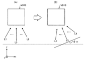
この点について、図11及び図12を用いて具体的に説明する。図11及び図12は、第1の実施形態における端末装置140による処理の一例を説明するための図である。図11は、被検体Pを上方(y方向)から見た図であり、図12は、ボリュームデータVD10をボリュームデータ空間の上(y方向)から見た図である。また、図11(A)は、基準位置が設定された際の端末装置140の位置を示す。また、図12(A)は、端末装置140が図11(A)に示した状態である場合にレンダリング処理部136によって行われるレンダリング処理時の視線方向L1等を示し、図12(B)は、端末装置140が図11(B)に示した状態である場合にレンダリング処理部136によって行われるレンダリング処理時の視線方向L1等を示す。なお、ここで、透視投影法によりレンダリング処理を行うものとする。
This point will be specifically described with reference to FIGS. 11 and 12. 11 and 12 are diagrams for explaining an example of processing performed by the
図11に示すように、端末装置140が、被検体Pを中心とする円弧状に回転移動させられたものとする。具体的には、端末装置140は、図11(A)に示す状態から、図11(B)に示す状態に移動させられたものとする。このとき、端末装置140の取得部1462は、基準位置における位置センサ145aの位置を始点とする位置センサ145aの移動ベクトルと、基準位置における位置センサ145bの位置を始点とする位置センサ145bの移動ベクトルとに基づいて、端末装置140の移動ベクトルと、基準位置における端末装置140に対する移動後の端末装置140の傾きθ11を取得する。
As shown in FIG. 11, it is assumed that the
具体的には、取得部1462は、位置センサ145a及び位置センサ145bの配置位置に基づいて、端末装置140の移動ベクトルを取得する。例えば、図11に示した例のように、位置センサ145a及び位置センサ145bが端末装置140の重心に対して左右対称に配置されている場合には、取得部1462は、双方の移動ベクトルに基づいて、端末装置140の移動ベクトルを取得することができる。また、取得部1462は、基準位置における位置センサ145a及び位置センサ145bの双方の位置を結ぶ直線と、移動後における双方の位置を結ぶ直線とのなす角度を算出することで、上記の傾きθ11を取得することができる。
Specifically, the acquisition unit 1462 acquires the movement vector of the
取得部1462は、このようにして取得した移動ベクトル及び端末装置140の傾きθ11をワークステーション130に送信する。このように、端末装置140は、横方向の異なる位置に2個の位置センサを有することで、端末装置140の横方向(x方向)に対する傾きθ11を取得することができる。
The acquisition unit 1462 transmits the movement vector acquired in this way and the inclination θ11 of the
端末装置140の移動ベクトル等を受信したワークステーション130の制御部135は、図10に示した例と同様に、移動ベクトルに基づいて、移動後の端末装置140がかざしている被検体Pの位置に対応するボリュームデータを特定する。さらに、制御部135は、図12に示すように、端末装置140の傾きθ11に基づいて、レンダリング処理時におけるボリュームデータVD10に対する視線方向を変更する。具体的には、制御部135は、図12(B)に示すように、レンダリング処理時の視点位置を移動後の端末装置140の位置とし、かかる視点位置からの視線方向L1等を傾きθ11だけ傾ける。制御部135は、このようなレンダリング条件によりレンダリング処理を行うようにレンダリング処理部136を制御する。そして、ワークステーション130は、レンダリング処理部136が生成した視差画像群を端末装置140に送信する。これにより、端末装置140は、ワークステーション130から受信した視差画像群を立体表示モニタ142に表示することで、被検体Pの側面や背面に移動させられた場合であっても、かざされた位置に対応する立体画像を表示することができる。
The control unit 135 of the
次に、図13及び図14を用いて、第1の実施形態におけるワークステーション130及び端末装置140による処理の流れの一例を示す。図13及び図14は、第1の実施形態における画像処理システムによる処理の流れの一例を示すシーケンス図である。なお、図13では、初期設定処理の流れについて説明し、図14では、端末装置140の移動時における表示処理の流れについて説明する。
Next, an example of the flow of processing by the
図13に示すように、端末装置140の初期設定部1461は、スキャノ像A10の一部分を表示させる操作を受け付けたか否かを判定する(ステップS101)。ここで、かかる操作を受け付けない場合には(ステップS101否定)、端末装置140は、待機する。一方、初期設定部1461によってかかる操作を受け付けた場合に(ステップS101肯定)、表示制御部1463は、スキャノ画像A10内の一部の画像を立体表示モニタ142に表示する(ステップS102)。
As illustrated in FIG. 13, the initial setting unit 1461 of the
続いて、初期設定部1461は、基準位置を設定する旨の操作を受け付けたか否かを判定する(ステップS103)。ここで、基準位置を設定する操作を受け付けない場合には(ステップS103否定)、端末装置140は、待機する。一方、初期設定部1461は、基準位置を設定する操作を受け付けた場合に(ステップS103肯定)、表示画像内の所定の位置を基準位置にすることを決定し、決定した基準位置をワークステーション130に送信する(ステップS104)。ワークステーション130の制御部135は、端末装置140から受信した基準位置に基づいて、ボリュームデータの基準位置を特定する(ステップS105)。
Subsequently, the initial setting unit 1461 determines whether an operation for setting the reference position has been received (step S103). Here, when the operation for setting the reference position is not accepted (No at Step S103), the
続いて、端末装置140の初期設定部1461は、スキャノ画像A10における表示画像の位置情報をワークステーション130に送信する(ステップS106)。ワークステーション130の制御部135は、表示画像の位置情報に対応するボリュームデータを特定し、特定したボリュームデータに対してレンダリング処理を行うようにレンダリング処理部136を制御する。これにより、レンダリング処理部136は、制御部135によって特定されたボリュームデータから視差画像群を生成する(ステップS107)。ワークステーション130は、生成した視差画像群を端末装置140に送信する(ステップS108)。
Subsequently, the initial setting unit 1461 of the
そして、端末装置140の表示制御部1463は、ワークステーション130から受信した視差画像群を立体表示モニタ142に表示する(ステップS109)。これにより、端末装置140は、表示画像(スキャノ画像A10の一部分の画像)に対応する立体画像を利用者に提供することができる。
Then, the display control unit 1463 of the
次に、図14を用いて、端末装置140が移動された場合について説明する。図14に示すように、端末装置140の取得部1462は、位置センサ145によって検出される位置情報に基づいて、端末装置140が移動されたか否かを判定する(ステップS201)。ここで、端末装置140が移動されない場合には(ステップS201否定)、端末装置140は、待機する。
Next, a case where the
一方、端末装置140が移動された場合に(ステップS201肯定)、取得部1462は、位置センサ145によって検出される位置情報に基づいて、端末装置140の移動ベクトル及び傾きを取得する(ステップS202)。そして、取得部1462は、取得した移動ベクトル及び傾きをワークステーション130に送信する(ステップS203)。
On the other hand, when the
ワークステーション130の制御部135は、端末装置140から取得した実空間における移動ベクトルをボリュームデータ空間における移動ベクトルに変換し、変換後の移動ベクトルに基づいて、移動後の端末装置140に対向する被検体Pの部位に対応するボリュームデータを特定する(ステップS204)。また、制御部135は、端末装置140の傾きに基づいて、レンダリング処理時の視線方向を決定する(ステップS205)。
The control unit 135 of the
そして、制御部135は、ステップS204において特定したボリュームデータに対して、ステップS205において決定した視線方向によりレンダリング処理を行うようにレンダリング処理部136を制御する。これにより、レンダリング処理部136は、視差画像群を生成する(ステップS206)。ワークステーション130は、生成した視差画像群を端末装置140に送信する(ステップS207)。
Then, the control unit 135 controls the
そして、端末装置140の表示制御部1463は、ワークステーション130から受信した視差画像群を立体表示モニタ142に表示する(ステップS208)。これにより、端末装置140は、端末装置140が対向する被検体Pの位置に対応する部位(臓器等)の立体画像を利用者に提供することができる。
Then, the display control unit 1463 of the
上述してきたように、第1の実施形態によれば、端末装置140が対向する被検体の部位を示す立体画像を表示することができるので、利用者が所望する立体画像を表示することができる。
As described above, according to the first embodiment, since the stereoscopic image indicating the part of the subject that the
なお、第1の実施形態は、上記の実施形態に限られず、以下に示すいくつかの変形例を含む態様の実施形態であってもよい。以下に、図15〜図18を用いて、第1の実施形態の変形例について説明する。 In addition, 1st Embodiment is not restricted to said embodiment, Embodiment of the aspect containing the some modification shown below may be sufficient. Below, the modification of 1st Embodiment is demonstrated using FIGS. 15-18.
[端末装置の傾き検出]
まず、上記第1の実施形態では、端末装置140が2個の位置センサ145を有することで、端末装置140の傾きを検出する例を示した。具体的には、図11及び図12に例示したように、上記例では、横方向(x方向)に対する端末装置140の傾きを検出した。しかし、第1の実施形態における端末装置140は、縦方向(y方向)と水平な状態を保って被検体Pにかざされるとは限らず、すなわち、縦方向(y方向)に対して傾けた状態で被検体Pにかざされる場合もある。第1の実施形態における端末装置140は、縦方向(y方向)に対して傾けた状態で被検体Pにかざされる場合であっても、かざしている位置に対応する被検体Pの立体画像を表示することができる。
[Detection of tilt of terminal device]
First, in the said 1st Embodiment, the
この点について、図15を用いて具体的に説明する。図15に示した例において、端末装置140は、図9等に示した例と同様に、上側面に位置センサ145a及び145bを有する。さらに、本変形例に係る端末装置140は、下側面に位置センサ145cを有する。図15に示した例において、端末装置140の取得部1462は、位置センサ145a、145b及び145cによって検出される位置情報に基づいて、被検体Pに対する端末装置140の相対的な位置変動を取得するとともに、横方向(x方向)に対する端末装置140の傾きθ11(図11及び図12参照)と、縦方向(y方向)に対する端末装置140の傾きθ12(図15参照)とを取得する。そして、取得部1462は、取得した移動ベクトル及び端末装置140の傾きθ11及びθ12をワークステーション130に送信する。なお、図15に示した例では、傾きθ11が「0」であるものとする。
This point will be specifically described with reference to FIG. In the example illustrated in FIG. 15, the
これらの各種情報を受信したワークステーション130の制御部135は、図15に示すように、ボリュームデータVD10からレンダリング対象とするボリュームデータVD13を特定する。具体的には、制御部135は、ボリュームデータ空間におけるxz平面に対して角度θ12だけ傾けたボリュームデータVD13を特定する。そして、制御部135は、特定したボリュームデータVD13に対してレンダリング処理を行うようにレンダリング処理部136を制御する。これにより、レンダリング処理部136(例えば、セグメンテーション処理部1361gや3次元幾何変換処理部1362b)は、レンダリング対象がボリュームデータVD13となるように視点位置及び視線方向を決定する。そして、レンダリング処理部136は、ボリュームデータVD13に対してボリュームレンダリング処理を行うことにより視差画像群を生成する。端末装置140は、レンダリング処理部136によって生成された視差画像群を立体表示モニタ142に表示することで、縦方向(y方向)に対して傾けられた場合であっても、かざされた位置に対応する被検体Pの立体画像を表示することができる。
The control unit 135 of the
なお、端末装置140に設けられる位置センサ145の数は、何個であってもよい。例えば、端末装置140が縦方向(y方向)に対して水平、かつ、被検体Pを中心とする円弧状のみで移動されることが予め決められている場合には、端末装置140は、1個の位置センサ145を有するだけでもよい。これは、端末装置140の移動態様が予め決められている場合には、ワークステーション130は、かかる移動態様に基づいて、1個の位置センサ145によって検出される端末装置140の位置に基づいて、端末装置140の向きを取得することができるからである。
Note that the number of position sensors 145 provided in the
また、例えば、端末装置140は、4個以上の位置センサ145を有してもよい。端末装置140に設けられる位置センサ145の数が多いほど、ワークステーション130は、かかる複数の位置センサ145によって検出される位置情報に基づいて、端末装置140の位置や向きを詳細に取得することが可能になる。
For example, the
[立体画像の縮小/拡大]
また、上記第1の実施形態における端末装置140は、被検体Pとの距離に応じて、立体表示モニタ142に表示する立体画像の表示形式を変更してもよい。例えば、端末装置140は、被検体Pとの距離に応じて、立体画像の縮尺を変化させてもよい。
[3D image reduction / enlargement]
In addition, the
この点について、図16を用いて具体的に説明する。図16(A1)は、端末装置140の基準位置が設定された状態であるものとする。また、図16(A2)は、基準位置に位置する端末装置140の立体表示モニタ142に表示される立体画像を示す。このような場合に、図16(B1)に示すように、端末装置140が被検体Pから遠ざかる方向に移動されたものとする。かかる場合に、端末装置140は、図16(B2)に示すように、基準位置において表示する立体画像(図16(A2)参照)よりも縮小した立体画像を表示する。また、ここでは、図示することを省略するが、端末装置140は、被検体Pに近づける方向に移動された場合には、基準位置において表示する立体画像(図16(A2)参照)よりも拡大した立体画像を表示する。
This point will be specifically described with reference to FIG. FIG. 16A1 illustrates a state in which the reference position of the
このような縮小/拡大表示を実現するために、ワークステーション130の制御部135は、端末装置140と被検体Pとの距離に応じて、縮小又は拡大された視差画像群を生成させる。例えば、制御部135は、端末装置140と被検体Pとの距離が離れているほど、レンダリング対象のボリュームデータを縮小し、縮小後のボリュームデータに対してレンダリング処理を行うようにレンダリング処理部136を制御する。また、例えば、制御部135は、端末装置140と被検体Pとの距離が近いほど、レンダリング対象のボリュームデータを拡大し、拡大後のボリュームデータに対してレンダリング処理を行うようにレンダリング処理部136を制御する。
In order to realize such reduced / enlarged display, the control unit 135 of the
また、上記第1の実施形態における端末装置140は、被検体Pとの距離に応じて、視差画像群の視差角を変化させることで、立体画像の立体感を変化させてもよい。具体的には、立体表示モニタ142によって表示される立体画像は、視差画像群を構成する視差画像間の視差角が大きいほど、奥行き方向(z方向)成分が大きくなり立体感が大きくなる。一方で、立体画像は、視差画像間の視差角が小さいほど、奥行き方向(z方向)成分が小さくなり立体感が小さくなる。
In addition, the
そこで、ワークステーション130の制御部135は、端末装置140と被検体Pとの距離に応じて、視差画像群の視差角を変化させる。例えば、制御部135は、端末装置140と被検体Pとの距離が離れているほど、小さい視差角によりレンダリング処理を行うようにレンダリング処理部136を制御する。一方で、制御部135は、端末装置140と被検体Pとの距離が近いほど、大きい視差角によりレンダリング処理を行うようにレンダリング処理部136を制御する。この例の場合には、端末装置140は、被検体Pに遠ざける方向に移動されるほど立体感の小さい立体画像を表示し、被検体Pに近づける方向に移動されるほど立体感の大きい立体画像を表示することができる。
Therefore, the control unit 135 of the
また、上記第1の実施形態における端末装置140は、被検体Pとの距離に応じて、立体画像のフォーカス位置を変化させてもよい。具体的には、ワークステーション130のレンダリング処理部136は、図6を用いて説明したように、複数の視点位置からレンダリング処理を行うが、かかる複数の視点位置からの視線方向は、ボリュームデータの所定の位置で交わる。このような各視線方向の交点は、かかる各視線方向からボリュームレンダリングが行われることで生成された視差画像群のフォーカスとなる。言い換えれば、視線方向を変更することで、視差画像群のフォーカス位置を変化させることができる。
Further, the
そこで、ワークステーション130の制御部135は、端末装置140と被検体Pとの距離に応じて、フォーカス(各視線方向の交点)を変化させる。例えば、制御部135は、端末装置140と被検体Pとの距離が離れているほど、利用者(観察者)から遠ざかる方向にフォーカスを移動させてレンダリング処理を行うようにレンダリング処理部136を制御する。一方で、制御部135は、端末装置140と被検体Pとの距離が近いほど、利用者(観察者)に近づく方向にフォーカスを移動させてレンダリング処理を行うようにレンダリング処理部136を制御する。この例の場合には、端末装置140は、被検体Pに遠ざける方向に移動されるほど、利用者(観察者)から遠ざかる方向にフォーカスが位置する立体画像を表示し、被検体Pに近づける方向に移動されるほど、利用者(観察者)から近づく方向にフォーカスが位置する立体画像を表示することができる。
Therefore, the control unit 135 of the
[立体画像の回転]
また、上記第1の実施形態における端末装置140は、立体表示モニタ142に立体画像を表示している状態において、端末装置140自体が揺動された場合に、立体画像を回転表示してもよい。この点について、図17を用いて具体的に説明する。端末装置140は、図17の上図に示すように揺動された場合に、図17の下図に示すように立体表示モニタ142に表示している立体画像を回転させてもよい。
[Rotate stereoscopic image]
Further, the
このような回転表示を実現するために、画像保管装置120は、ボリュームデータVD10を中心とする円弧状に所定の角度(例えば、1度)ずつ配置された複数の視点位置からレンダリングされた全周囲の視差画像群を有する。そして、端末装置140は、揺動操作に応じて、表示対象の視差画像群を画像保管装置120から取得し、立体表示モニタ142に表示する。または、端末装置140は、全周囲の視差画像群を有し、揺動操作に応じて全周囲の視差画像群から表示対象の視差画像を選択し、選択した視差画像群を立体表示モニタ142に表示してもよい。
In order to realize such a rotation display, the image storage device 120 has the entire periphery rendered from a plurality of viewpoint positions arranged at predetermined angles (for example, 1 degree) in an arc shape centered on the volume data VD10. Of parallax images. Then, the
なお、上記例において、端末装置140は、加速度センサを有してもよい。そして、端末装置140は、かかる加速度センサによって揺動方向及び揺動速度を検出し、検出した揺動方向に応じて立体画像の回転方向を決定し、揺動速度に応じて立体画像の回転量を決定してもよい。
In the above example, the
[表示変動の抑止]
また、上記第1の実施形態における端末装置140は、移動されずに回転のみされた場合には、立体表示モニタ142に表示する立体画像を変化させなくてもよい。この点について、図18を用いて具体的に説明する。図18(A1)は、端末装置140の基準位置が設定された状態であるものとする。また、図18(A2)は、基準位置に位置する端末装置140の立体表示モニタ142に表示される立体画像を示す。
[Suppression of display fluctuation]
Further, when the
このような場合に、端末装置140は、図18(B1)に示すように移動された場合には、図11及び図12を用いて説明したように、かざされた位置に対応する被検体Pの立体画像を表示する(図18(B2)参照)。ここで、端末装置140は、図18(C1)に示すように、端末装置140の重心位置が変動せず、かかる重心を中心に回転動作のみされた場合には、図18(C2)に示すように、立体表示モニタ142に表示する立体画像を変化させずに、図18(B2)に示した立体画像を表示したままとしてもよい。これにより、利用者は、利用者自身が移動することなく、被検体Pの側面の立体画像を観察することができる。
In such a case, when the
[パターンマッチング]
また、上記第1の実施形態において、端末装置140は、基準位置を設定する旨の操作を受け付け、位置センサ145によって検出される位置情報に基づいて端末装置140の移動ベクトルを取得した。そして、ワークステーション130は、ボリュームデータVD10に基準位置を設定し、端末装置140の移動ベクトルに基づいて、端末装置140がかざしている位置に対応する被検体Pの視差画像群を生成した。しかし、端末装置140と被検体Pとの位置関係を取得する処理は、この例に限られない。例えば、第1の実施形態における端末装置140は、基準位置を設定する旨の操作を受け付けず、また、位置センサ145を有しなくてもよい。
[Pattern matching]
In the first embodiment, the
具体的には、端末装置140は、被検体Pを撮影可能なカメラを有し、被検体Pにかざされた状態で所定の操作が行われた場合に、カメラに被検体Pを撮影させる。そして、端末装置140の取得部1462は、領域拡張(region growing)法や形状テンプレートを用いたパターンマッチング法などを用いて、スキャノ画像A10のうちカメラによって撮影された画像が示す位置を特定する。すなわち、端末装置140は、パターンマッチング法などを用いて、スキャノ画像A10と撮影画像との輪郭をマッチングさせることにより、端末装置140がかざされている被検体Pの位置を特定する。そして、端末装置140は、特定した被検体Pの位置をワークステーション130に送信することにより、かかる位置に対応する被検体Pの視差画像群をワークステーション130から取得する。これにより、端末装置140は、かざされている位置に対応する被検体Pの立体画像を立体表示モニタ142に表示することができる。なお、パターンマッチング法を用いて端末装置140がかざされている被検体Pの位置を特定する場合には、端末装置140は、上記の初期設定部1461を有しなくてもよい。
Specifically, the
[2次元画像]
また、上記第1の実施形態における端末装置140は、被検体Pにかざされた場合に、かざされた位置に対応する部位(臓器等)の視差画像群を表示することで、かかる臓器等の立体画像を利用者に提供した。しかし、端末装置140は、視差画像群を表示せずに、2次元画像(例えば、CT画像やMPR画像等)を表示してもよい。すなわち、上記第1の実施形態における端末装置140は、ワークステーション130によってボリュームデータから生成された視差画像群を表示したが、ワークステーション130によってボリュームデータから生成される2次元画像を表示してもよい。かかる場合には、ワークステーション130は、端末装置140の移動ベクトルを受信した場合に、ボリュームデータから生成される2次元画像を生成し、生成した2次元画像を端末装置140に送信する。
[2D image]
In addition, when the
このように、端末装置140は、かざされた位置に対応する被検体Pの2次元画像を表示する場合であっても、被検体Pとの距離に応じて立体表示モニタ142に表示する立体画像の表示形式を変更してもよい。例えば、端末装置140は、図16に示した例と同様に、被検体Pとの距離に応じて2次元画像の縮尺を変化させてもよい。
Thus, even when the
また、例えば、端末装置140は、2次元画像を表示する場合には、被検体Pとの距離に応じて表示対象の2次元の断面画像を変化させてもよい。具体的には、端末装置140は、端末装置140の移動ベクトルをワークステーション130に送信する。ワークステーション130の制御部135は、端末装置140の移動ベクトルに基づいて、端末装置140と被検体Pとの距離が遠いほど、被検体P内部のうち端末装置140に近い部位の断面画像を生成し、端末装置140と被検体Pとの距離が近いほど、被検体P内部のうち端末装置140から離れている部位の断面画像を生成する。そして、ワークステーション130は、生成した断面画像を端末装置140に送信する。
Further, for example, when displaying a two-dimensional image, the
これにより、端末装置140は、被検体Pとの距離に応じた2次元の断面画像を表示することができる。具体的には、端末装置140は、被検体Pから遠ざかる方向に移動された場合に、被検体P内部のうち端末装置140に近い部位の断面画像を表示し、被検体Pに近づける方向に移動された場合に、被検体P内部のうち端末装置140から遠い部位の断面画像を表示することができる。この点について、図16に示した例を用いて説明する。例えば、端末装置140は、図16(A1)に示した状態である場合に、被検体Pの心臓の断面画像を表示するものとする。このとき、端末装置140は、図16(B1)に示すように被検体Pから遠ざかる方向に移動された場合に、被検体P内部のうち、図16(A1)に示した状態において表示した心臓よりも端末装置140に近づく方向の部位(例えば、胸骨等)の断面画像を表示する。また、端末装置140は、被検体Pに近づける方向に移動された場合に、被検体P内部のうち、図16(A1)に示した状態において表示した心臓よりも端末装置140から離れる方向の部位(例えば、背骨等)の断面画像を表示する。
Accordingly, the
また、上記第1の実施形態においては、端末装置140がタブレット式PC等の持ち運び可能な端末であるものとして説明した。しかし、端末装置140の実施形態はこれに限られない。例えば、第1の実施形態における端末装置140は、端末装置140を上下左右に移動可能な可動式アーム等によって固定されてもよい。
In the first embodiment, the
(第2の実施形態)
上記第1の実施形態では、端末装置140と被検体Pとの位置関係に応じて、端末装置140の立体表示モニタ142に表示する立体画像の表示形式を変化させる例を示した。第2の実施形態では、端末装置と利用者(観察者)との位置関係に応じて、立体表示モニタ142に表示する立体画像の表示形式を変化させる例について説明する。
(Second Embodiment)
In the first embodiment, the example in which the display format of the stereoscopic image displayed on the stereoscopic display monitor 142 of the
まず、第2の実施形態における画像処理システムを説明する前に、図19を用いて、立体表示モニタによって表示される立体画像について説明する。図19は、立体画像と観察位置との関係を説明するための図である。図19に示した例において、立体表示モニタは、観察者によって立体視可能な立体画像を表示する。ここで、観察者にとって立体画像を立体的に視認しやすい観察位置は、所定の領域に決定される。一般的には、観察位置が立体表示モニタの正面や斜め45°である場合には、観察者は立体画像を立体的に視認しやすいことが多い。例えば、図19に示した例において、観察者は、領域R11、R12及びR13から立体表示モニタを観察する場合には、立体画像を立体的に視認しやすいが、領域R21及びR22から観察する場合には、立体画像を立体的に視認しにくいことがある。この例の場合、観察者は、領域R21から立体画像の右側面を立体的に視認することが困難になる。 First, before describing the image processing system according to the second embodiment, a stereoscopic image displayed on a stereoscopic display monitor will be described with reference to FIG. FIG. 19 is a diagram for explaining the relationship between a stereoscopic image and an observation position. In the example illustrated in FIG. 19, the stereoscopic display monitor displays a stereoscopic image that can be stereoscopically viewed by an observer. Here, the observation position at which the observer can easily visually recognize the stereoscopic image is determined as a predetermined area. In general, when the observation position is in front of the stereoscopic display monitor or at an oblique angle of 45 °, the observer often tends to visually recognize the stereoscopic image in three dimensions. For example, in the example illustrated in FIG. 19, when the observer observes the stereoscopic display monitor from the regions R11, R12, and R13, the stereoscopic image is easily viewed stereoscopically, but the observer observes from the regions R21, R22. In some cases, it is difficult to view a stereoscopic image stereoscopically. In the case of this example, it becomes difficult for the observer to visually recognize the right side surface of the stereoscopic image from the region R21.
そこで、第2の実施形態における端末装置では、観察者の観察位置に応じて、立体表示モニタの向きを変化させるとともに、立体画像を回転表示する。以下に、このような第2の実施形態における端末装置240について詳細に説明する。
Therefore, in the terminal device according to the second embodiment, the direction of the stereoscopic display monitor is changed according to the observation position of the observer, and the stereoscopic image is rotated and displayed. Hereinafter, the
まず、図20を用いて、第2の実施形態における端末装置240の外観について説明する。図20は、第2の実施形態における端末装置240の外観を示す図である。図20に例示するように、端末装置240は、立体表示モニタ142とともに回転可能な回転部22と、利用者(観察者)の位置を取得可能な位置センサ245とを有する。
First, the external appearance of the
次に、図20に示した第2の実施形態における端末装置240の構成例について説明する。図21は、第2の実施形態における端末装置240の構成例を説明するための図である。図21に示した端末装置240は、図1に示した端末装置140に対応する。なお、以下では、既に示した構成部位と同様の機能を有する部位には同一符号を付すこととして、その詳細な説明を省略する。図20に例示するように、第2の実施形態における端末装置240は、位置センサ245と、制御部246とを有する。
Next, a configuration example of the
位置センサ245は、図20に例示したように、立体表示モニタ142に設けられる。かかる位置センサ245は、立体表示モニタ142を観察している観察者の端末装置240に対する相対的の位置である観察位置を取得する。
The
制御部246は、CPU、MPUやGPU等の電子回路、ASICやFPGA等の集積回路であり、端末装置240の全体制御を行う。かかる制御部246は、取得部2461と、回転制御部2462と、表示制御部2463とを有する。
The
取得部2461は、位置センサ245によって取得された観察位置に基づいて、所定の基準方向と、観察者の立体表示モニタ142への視線方向(端末装置240と観察位置とを結ぶ直線)とのなす角度を取得する。なお、第2の実施形態においては、所定の基準方向が、立体表示モニタ142の表示面に垂直な方向(奥行き方向、z方向)であるものとする。また、以下では、基準方向と視線方向とのなす角度を「観察角度」と表記する場合がある。
Based on the observation position acquired by the
また、取得部2461は、位置センサ245によって取得された観察位置から立体表示モニタ142への視線方向に対応する視差画像群をワークステーション130から取得する。具体的には、取得部2461は、観察角度をワークステーション130に送信することで、視線方向に対応する視差画像群を取得する。この点については後述する。
Further, the
回転制御部2462は、取得部2461によって取得された観察角度に基づいて、立体表示モニタ142の表示面が観察位置に向くように、回転部22を回転させる。具体的には、回転制御部2462は、観察位置から立体表示モニタ142への視線方向と、立体表示モニタ142の表示面とが垂直関係(対向関係)になるように、回転部22を回転させる。
Based on the observation angle acquired by the
表示制御部2463は、ワークステーション130から受信した視差画像群を立体表示モニタ142に表示する。また、第2の実施形態における表示制御部2463は、取得部2461によってワークステーション130から視差画像群が取得された場合に、かかる視差画像群を立体表示モニタ142に表示する。
The
ここで、図22を用いて、第2の実施形態における取得部2461、回転制御部2462及び表示制御部2463による処理の一例について説明する。図22は、第2の実施形態における端末装置240による処理の一例を説明するための図である。
Here, an example of processing by the
図22に示した例において、観察者Uは、立体表示モニタ142によって表示されている立体画像I11を観察する。かかる場合に、端末装置240の位置センサ245は、端末装置240に対する観察者Uの位置を観察位置として取得する。図22(A1)に示した例では、観察者Uが立体表示モニタ142の正面に位置するので、このような場合には、端末装置240の回転制御部2462は処理を行わない。なお、ここでは、立体表示モニタ142は、図22(A2)に例示した視線方向L1、・・・、L5、・・・、L9によりレンダリング処理が行われることで生成された視差画像群を表示しているものとする。
In the example illustrated in FIG. 22, the observer U observes the stereoscopic image I11 displayed by the
続いて、図22(B1)に示した例のように、観察者Uが立体表示モニタ142の左斜め前方に移動したものとする。すなわち、観察者Uは、立体画像I11の左側面を立体的に視認することを望んでいると考えられる。
Subsequently, as in the example illustrated in FIG. 22 (B1), it is assumed that the observer U has moved diagonally to the left of the
かかる場合には、取得部2461は、位置センサ245によって取得された観察者Uの観察位置に基づいて、基準方向と視線方向とのなす観察角度θ21を取得する。そして、取得部2461は、観察位置及び観察角度θ21をワークステーション130に送信する。観察位置及び観察角度θ21を受け付けたワークステーション130の制御部135は、図22(B2)に示すように、レンダリング処理時の視点位置を端末装置240から受信した観察位置とし、かかる視点位置からの視線方向L1等を観察角度θ21だけ傾ける。制御部135は、このようなレンダリング条件によりレンダリング処理を行うようにレンダリング処理部136を制御する。そして、ワークステーション130は、レンダリング処理部136が生成した視差画像群を端末装置240に送信する。
In such a case, the
そして、端末装置240の回転制御部2462は、図22(B1)に示すように、取得部2461によって取得された観察角度θ21に基づいて、立体表示モニタ142の表示面が観察者Uと正対するように、回転部22を観察角度θ21だけ回転させる。
Then, the
また、端末装置240の表示制御部2463は、図22(B1)に示すように、ワークステーション130から受信した視差画像群を立体表示モニタ142に表示することで、立体画像I12を観察者Uに提供する。すなわち、立体表示モニタ142は、正面から観察された場合に、立体画像I11の左側面に対応する立体画像I12を表示する。図22(B1)に示すように、観察者Uは、立体表示モニタ142を正面から観察しているので、立体画像I12を立体的に視認することができ、さらに、自身が移動した方向から立体画像I11を視認しているように感じることができる。
In addition, the
なお、上記図22では、回転制御部2462が回転部22を観察角度θ21だけ回転させることにより、立体表示モニタ142と観察者とを対向させる例を示した。しかし、回転制御部2462は、回転部22を観察角度θ21だけ回転させなくてもよい。具体的には、図19を用いて説明したように、立体表示モニタ142と観察者とを対向しない場合であっても、観察者にとって立体画像を立体的に視認しやすい領域が存在する。このため、回転制御部2462は、かかる領域(例えば、図19に例示した領域R11)に観察者が位置するように回転部22を回転させればよい。
FIG. 22 shows an example in which the
次に、図23を用いて、第2の実施形態におけるワークステーション130及び端末装置240による処理の流れの一例を示す。図23は、第2の実施形態における画像処理システムによる処理の流れの一例を示すシーケンス図である。
Next, an example of the flow of processing by the
図23に示すように、端末装置240の取得部2461は、位置センサ245によって検出される位置情報に基づいて、観察者が移動したか否かを判定する(ステップS301)。ここで、観察者の移動を検出しない場合には(ステップS301否定)、端末装置240は、待機する。
As illustrated in FIG. 23, the
一方、観察者の移動を検出した場合に(ステップS201肯定)、取得部2461は、位置センサ245によって取得された観察者の観察位置に基づいて、観察角度を取得する(ステップS302)。続いて、端末装置240の回転制御部2462は、立体表示モニタ142の表示面が観察者と正対するように、回転部22を観察角度θ21だけ回転させる(ステップS303)。そして、取得部2461は、観察位置及び観察角度をワークステーション130に送信する(ステップS304)。
On the other hand, when the movement of the observer is detected (Yes at Step S201), the
ワークステーション130の制御部135は、端末装置240から受信した観察位置及び観察角度に基づいて、レンダリング処理時の視線方向を決定する(ステップS305)。そして、制御部135は、ステップS304において決定した視線方向によりレンダリング処理を行うようにレンダリング処理部136を制御する。これにより、レンダリング処理部136は、視差画像群を生成する(ステップS306)。ワークステーション130は、生成した視差画像群を端末装置240に送信する(ステップS307)。
The control unit 135 of the
そして、端末装置240の表示制御部2463は、ワークステーション130から受信した視差画像群を立体表示モニタ142に表示する(ステップS308)。
Then, the
上述してきたように、第2の実施形態によれば、観察者の観察位置に応じた立体画像を表示することができるので、利用者が所望する立体画像を表示することができる。 As described above, according to the second embodiment, since a stereoscopic image corresponding to the observation position of the observer can be displayed, a stereoscopic image desired by the user can be displayed.
なお、第2の実施形態は、上記の実施形態に限られず、以下に示すいくつかの変形例を含む態様の実施形態であってもよい。以下に、第2の実施形態の変形例について説明する。 In addition, 2nd Embodiment is not restricted to said embodiment, Embodiment of the aspect containing the some modification shown below may be sufficient. Below, the modification of 2nd Embodiment is demonstrated.
[手動回転]
なお、上記第2の実施形態において、端末装置240は、観察者等によって手動で回転移動されてもよい。かかる場合に、端末装置240は、自装置の回転量に応じて、表示対象の視差画像群を変更する。この点について、図24を用いて具体的に説明する。図24は、第2の実施形態の変形例を説明するための図である。
[Manual rotation]
In the second embodiment, the
図24に示した例において、端末装置240は、立体表示モニタ142と本体部とが回転可能な回転部22によって連結された携帯電話等であるものとする。このような携帯電話等の場合には、観察者は、利用形態によって立体表示モニタ142を回転させることがあるものの、回転後の立体表示モニタ142を正面から観察することが多い。
In the example illustrated in FIG. 24, the
ここで、図24(A)及び(B)に示すように、立体画像I11を表示している端末装置240の立体表示モニタ142が90度回転されたものとする。かかる場合に、端末装置240は、立体表示モニタ142の回転量「90度」をワークステーション130に送信する。このとき、ワークステーション130の制御部135は、図24(A)において表示されている視差画像群が生成された際の視点位置を90度回転移動させ、かかる視点位置からレンダリング処理を行うようにレンダリング処理部136を制御する。
Here, as shown in FIGS. 24A and 24B, it is assumed that the stereoscopic display monitor 142 of the
端末装置240は、図24(B)に示すように、このようにしてレンダリング処理部136によって生成された視差画像群を立体表示モニタ142に表示する。これにより、端末装置240は、立体画像I11の左側面に対応する立体画像I13を観察者Uに提供することができる。この結果、観察者Uは、立体表示モニタ142を正面から観察しているので、立体画像I13を立体的に視認することができ、さらに、立体表示モニタ142の回転量に応じて回転された立体画像I11を視認しているように感じることができる。
The
[ヘッドトラッキング]
また、上記第2の実施形態では、端末装置240が観察者の観察位置を取得する位置センサ245を有する例を示した。しかし、端末装置240は、観察者を撮影するカメラを有し、カメラによる撮影画像をヘッドトラッキング等の技術により解析することで、観察者の観察位置を取得してもよい。
[Head tracking]
Moreover, in the said 2nd Embodiment, the
(第3の実施形態)
さて、上述した実施形態は、他の実施形態に変形することもできる。そこで、第3の実施形態では、上述した実施形態の変形例を説明する。
(Third embodiment)
Now, the embodiment described above can be modified to other embodiments. Therefore, in the third embodiment, a modified example of the above-described embodiment will be described.
[処理主体]
上記実施形態においては、端末装置140又は240が、自装置の移動や観察位置の移動に対応する視差画像群をワークステーション130から取得する例について説明した。しかし、端末装置140又は240は、ワークステーション130の制御部135やレンダリング処理部136等と同様の機能を有してもよい。かかる場合には、端末装置140又は240は、画像保管装置120からボリュームデータを取得し、上記の制御部135と同様の処理を行う。
[Processing entity]
In the above embodiment, the example in which the
また、上記実施形態において、ワークステーション130がボリュームデータから視差画像群を生成するのではなく、医用画像診断装置110が、レンダリング処理部136と同等の機能を有し、ボリュームデータから視差画像群を生成してもよい。かかる場合には、端末装置140又は240は、医用画像診断装置110から視差画像群を取得する。
In the above embodiment, the
[視差画像数]
また、上記実施形態においては、主に9つの視差画像である視差画像群に対して、図形画像を重畳させて表示する例について説明したが、実施形態はこれに限られるものではない。例えば、ワークステーション130は、2つの視差画像である視差画像群を生成してもよい。
[Number of parallax images]
In the above-described embodiment, an example in which a graphic image is superimposed and displayed on a group of parallax images that are mainly nine parallax images has been described, but the embodiment is not limited thereto. For example, the
[システム構成]
また、上記実施形態において説明した各処理のうち、自動的に行われるものとして説明した処理の全部又は一部を手動的に行うこともでき、あるいは、手動的に行われるものとして説明した処理の全部又は一部を公知の方法で自動的に行うこともできる。この他、上述文書中や図面中で示した処理手順、制御手順、具体的名称、各種のデータやパラメータを含む情報については、特記する場合を除いて任意に変更することができる。
[System configuration]
In addition, among the processes described in the above embodiment, all or part of the processes described as being performed automatically can be performed manually, or the processes described as being performed manually can be performed. All or a part can be automatically performed by a known method. In addition, the processing procedures, control procedures, specific names, and information including various data and parameters shown in the above-described document and drawings can be arbitrarily changed unless otherwise specified.
また、図示した各装置の各構成要素は機能概念的なものであり、必ずしも物理的に図示の如く構成されていることを要しない。すなわち、各装置の分散・統合の具体的形態は図示のものに限られず、その全部又は一部を、各種の負荷や使用状況などに応じて、任意の単位で機能的又は物理的に分散・統合して構成することができる。例えば、ワークステーション130の制御部135をワークステーション130の外部装置としてネットワーク経由で接続するようにしてもよい。
Further, each component of each illustrated apparatus is functionally conceptual, and does not necessarily need to be physically configured as illustrated. That is, the specific form of distribution / integration of each device is not limited to the one shown in the figure, and all or a part of the distribution / integration may be functionally or physically distributed in arbitrary units according to various loads or usage conditions. Can be integrated and configured. For example, the control unit 135 of the
[プログラム]
また、上記実施形態における端末装置140又は240が実行する処理をコンピュータが実行可能な言語で記述したプログラムを作成することもできる。この場合、コンピュータがプログラムを実行することにより、上記実施形態と同様の効果を得ることができる。さらに、かかるプログラムをコンピュータ読み取り可能な記録媒体に記録して、この記録媒体に記録されたプログラムをコンピュータに読み込ませて実行することにより上記実施形態と同様の処理を実現してもよい。例えば、かかるプログラムは、ハードディスク、フレキシブルディスク(FD)、CD−ROM、MO、DVD、ブルーレイ等に記録される。また、かかるプログラムは、インターネットなどのネットワークを介して配布することもできる。
[program]
In addition, it is possible to create a program in which processing executed by the
本発明のいくつかの実施形態を説明したが、これらの実施形態は、例として提示したものであり、発明の範囲を限定することは意図していない。これら実施形態は、その他の様々な形態で実施されることが可能であり、発明の要旨を逸脱しない範囲で、種々の省略、置き換え、変更を行うことができる。これら実施形態やその変形は、発明の範囲や要旨に含まれると同様に、特許請求の範囲に記載された発明とその均等の範囲に含まれるものである。 Although several embodiments of the present invention have been described, these embodiments are presented by way of example and are not intended to limit the scope of the invention. These embodiments can be implemented in various other forms, and various omissions, replacements, and changes can be made without departing from the spirit of the invention. These embodiments and their modifications are included in the scope and gist of the invention, and are also included in the invention described in the claims and the equivalents thereof.
1 画像処理システム
110 医用画像診断装置
120 画像保管装置
130 ワークステーション
135 制御部
140 端末装置
142 立体表示モニタ
145 位置センサ
1461 初期設定部
1462 取得部
1463 表示制御部
2461 取得部
2462 回転制御部
2463 表示制御部
DESCRIPTION OF
Claims (9)
前記医用画像診断装置によって生成されたボリュームデータを記憶する記憶部と、
前記被検体に対する前記端末装置の位置と、前記端末装置と前記被検体との間の距離とを取得する取得部と、
前記記憶部が記憶するボリュームデータに対して、前記端末装置に対向する被検体の医用画像の部位に対応する視差画像群を生成するようにレンダリング処理を行うレンダリング処理部と、
前記レンダリング処理部によって生成される視差画像群を前記表示部に表示させる表示制御部とを備え、
前記レンダリング処理部は、前記取得部によって取得された前記位置及び前記距離に基づいて、レンダリング処理時の視点位置と視線方向とを決定し、決定した視点位置と視線方向とを用いて前記ボリュームデータに対してレンダリング処理を行い、
前記取得部は、所定の基準位置からの前記端末装置の位置変動を示す移動ベクトルを取得し、
前記レンダリング処理部は、前記取得部によって取得された前記端末装置の移動ベクトルに基づいて、前記視点位置及び前記視線方向を決定し、決定した視点位置及び視線方向により前記ボリュームデータに対してレンダリング処理を行うことで、移動後の端末装置に対向する被検体の部位を示す視差画像群を生成し、
前記表示制御部は、移動後の端末装置に対向する被検体の部位を示す視差画像群を前記表示部に表示させ、前記取得部によって、同一位置において前記端末装置が回転されたことを示す移動ベクトルが取得された場合に、前記端末装置が回転される前の視差画像群を前記表示部に表示させる、画像処理システム。 An image processing system comprising: a medical image diagnostic apparatus that generates volume data that is three-dimensional medical image data of a subject; and a terminal device that includes a display unit that displays a stereoscopic image that can be stereoscopically viewed using a parallax image group. Because
A storage unit for storing volume data generated by the medical image diagnostic apparatus;
An acquisition unit that acquires a position of the terminal device with respect to the subject and a distance between the terminal device and the subject;
A rendering processing unit that performs rendering processing on the volume data stored in the storage unit so as to generate a parallax image group corresponding to a portion of a medical image of a subject facing the terminal device;
A display control unit that causes the display unit to display a parallax image group generated by the rendering processing unit;
The rendering processing unit determines a viewpoint position and a line-of-sight direction during rendering processing based on the position and the distance acquired by the acquisition unit, and uses the determined viewpoint position and line-of-sight direction to determine the volume data. There line rendering processing on,
The acquisition unit acquires a movement vector indicating a position variation of the terminal device from a predetermined reference position,
The rendering processing unit determines the viewpoint position and the line-of-sight direction based on the movement vector of the terminal device acquired by the acquisition unit, and renders the volume data according to the determined viewpoint position and line-of-sight direction To generate a parallax image group indicating a portion of the subject facing the terminal device after movement,
The display control unit causes the display unit to display a parallax image group indicating a portion of the subject facing the terminal device after movement, and the acquisition unit moves the terminal device at the same position. An image processing system for causing a display unit to display a group of parallax images before the terminal device is rotated when a vector is acquired .
前記医用画像診断装置によって生成されたボリュームデータを記憶する記憶部と、A storage unit for storing volume data generated by the medical image diagnostic apparatus;
前記被検体に対する前記端末装置の位置と、前記端末装置と前記被検体との間の距離とを取得する取得部と、An acquisition unit that acquires a position of the terminal device with respect to the subject and a distance between the terminal device and the subject;
立体画像を表示する場合には、前記記憶部が記憶するボリュームデータに対して、前記端末装置に対向する被検体の医用画像の部位に対応する視差画像群を生成するようにレンダリング処理を行い、2次元画像を表示する場合には、前記ボリュームデータに対してレンダリング処理を行うことで被検体の断面画像を生成するレンダリング処理部と、When displaying a stereoscopic image, rendering processing is performed on the volume data stored in the storage unit so as to generate a parallax image group corresponding to a portion of the medical image of the subject facing the terminal device, In the case of displaying a two-dimensional image, a rendering processing unit that generates a cross-sectional image of the subject by performing a rendering process on the volume data;
立体画像を表示する場合には、前記レンダリング処理部によって生成される視差画像群を前記表示部に表示させ、2次元画像を表示する場合には、前記レンダリング処理部によって生成された断面画像を前記表示部に表示させる表示制御部とを備え、When displaying a stereoscopic image, the parallax image group generated by the rendering processing unit is displayed on the display unit, and when displaying a two-dimensional image, the cross-sectional image generated by the rendering processing unit is displayed on the display unit. A display control unit for displaying on the display unit,
前記レンダリング処理部は、立体画像を表示する場合には、前記取得部によって取得された前記位置及び前記距離に基づいて、レンダリング処理時の視点位置と視線方向とを決定し、決定した視点位置と視線方向とを用いて前記ボリュームデータに対してレンダリング処理を行い、2次元画像を表示する場合には、前記取得部によって取得された前記被検体に対する端末装置の位置に基づいて、前記端末装置と前記被検体との距離が遠いほど、前記被検体内部のうち前記端末装置に近い部位の断面画像を生成し、前記端末装置と前記被検体との距離が近いほど、前記被検体内部のうち前記端末装置から離れている部位の断面画像を生成する、画像処理システム。The rendering processing unit, when displaying a stereoscopic image, determines a viewpoint position and a line-of-sight direction at the time of rendering processing based on the position and the distance acquired by the acquisition unit, and the determined viewpoint position When rendering the volume data using a line-of-sight direction and displaying a two-dimensional image, based on the position of the terminal device with respect to the subject acquired by the acquisition unit, As the distance from the subject increases, a cross-sectional image of a portion near the terminal device in the subject is generated, and as the distance between the terminal device and the subject decreases, the cross-section image in the subject increases. An image processing system that generates a cross-sectional image of a part away from a terminal device.
前記取得部は、前記撮影部によって撮影された撮影画像と、該撮影画像よりも広範囲に撮影された前記被検体の被検体画像とを比較することにより、前記撮影部によって撮影された被検体の位置を取得する、請求項1又は2に記載の画像処理システム。 Further comprising an imaging unit for imaging the subject,
The acquisition unit compares the photographed image photographed by the photographing unit with the subject image of the subject photographed in a wider range than the photographed image, so that the subject photographed by the photographing unit acquiring the position, the image processing system according to claim 1 or 2.
前記取得部によって取得された前記端末装置と前記被検体との距離に応じて、縮小又は拡大した視差画像群を生成する、請求項1〜3のいずれか一つに記載の画像処理システム。 The rendering processing unit
The image processing system according to claim 1, wherein a reduced or enlarged parallax image group is generated according to a distance between the terminal device acquired by the acquisition unit and the subject.
前記取得部によって取得された前記端末装置と前記被検体との距離に応じて、視差画像群を構成する視差画像間の視差角を決定し、決定した視差角により前記ボリュームデータに対してレンダリング処理を行うことで前記被検体の視差画像群を生成する、請求項1〜4のいずれか一つに記載の画像処理システム。 The rendering processing unit
A parallax angle between parallax images constituting a parallax image group is determined according to a distance between the terminal device acquired by the acquisition unit and the subject, and rendering processing is performed on the volume data based on the determined parallax angle The image processing system according to claim 1, wherein a parallax image group of the subject is generated by performing the step.
視差画像群を用いて立体視可能な立体画像を表示する表示部と、
被検体に対する前記端末装置の位置と、前記端末装置と前記被検体との間の距離とを取得する取得部と、
前記記憶部が記憶するボリュームデータに対して、前記端末装置に対向する被検体の医用画像の部位に対応する視差画像群を生成するようにレンダリング処理を行うレンダリング処理部と、
前記レンダリング処理部によって生成される視差画像群を表示させる表示制御部と、
を備え、
前記レンダリング処理部は、前記取得部によって取得された前記位置及び前記距離に基づいて、レンダリング処理時の視点位置と視線方向とを決定し、決定した視点位置と視線方向とを用いて前記ボリュームデータに対してレンダリング処理を行い、
前記取得部は、所定の基準位置からの前記端末装置の位置変動を示す移動ベクトルを取得し、
前記レンダリング処理部は、前記取得部によって取得された前記端末装置の移動ベクトルに基づいて、前記視点位置及び前記視線方向を決定し、決定した視点位置及び視線方向により前記ボリュームデータに対してレンダリング処理を行うことで、移動後の端末装置に対向する被検体の部位を示す視差画像群を生成し、
前記表示制御部は、移動後の端末装置に対向する被検体の部位を示す視差画像群を前記表示部に表示させ、前記取得部によって、同一位置において前記端末装置が回転されたことを示す移動ベクトルが取得された場合に、前記端末装置が回転される前の視差画像群を前記表示部に表示させる、端末装置。 A medical image diagnostic apparatus that generates volume data that is three-dimensional medical image data of a subject, and that displays a medical image generated by a medical image diagnostic apparatus connected to a storage unit that stores the volume data A device,
A display unit for displaying a stereoscopically viewable stereoscopic image using the parallax image group;
An acquisition unit that acquires a position of the terminal device with respect to a subject and a distance between the terminal device and the subject;
A rendering processing unit that performs rendering processing on the volume data stored in the storage unit so as to generate a parallax image group corresponding to a portion of a medical image of a subject facing the terminal device;
A display control unit for displaying a group of parallax images generated by the rendering processing unit;
With
The rendering processing unit determines a viewpoint position and a line-of-sight direction during rendering processing based on the position and the distance acquired by the acquisition unit, and uses the determined viewpoint position and line-of-sight direction to determine the volume data. There line rendering processing on,
The acquisition unit acquires a movement vector indicating a position variation of the terminal device from a predetermined reference position,
The rendering processing unit determines the viewpoint position and the line-of-sight direction based on the movement vector of the terminal device acquired by the acquisition unit, and renders the volume data according to the determined viewpoint position and line-of-sight direction To generate a parallax image group indicating a portion of the subject facing the terminal device after movement,
The display control unit causes the display unit to display a parallax image group indicating a portion of the subject facing the terminal device after movement, and the acquisition unit moves the terminal device at the same position. A terminal device that displays a parallax image group before the terminal device is rotated on the display unit when a vector is acquired .
視差画像群を用いて立体視可能な立体画像を表示する表示部と、A display unit for displaying a stereoscopically viewable stereoscopic image using the parallax image group;
被検体に対する前記端末装置の位置と、前記端末装置と前記被検体との間の距離とを取得する取得部と、An acquisition unit that acquires a position of the terminal device with respect to a subject and a distance between the terminal device and the subject;
立体画像を表示する場合には、前記記憶部が記憶するボリュームデータに対して、前記端末装置に対向する被検体の医用画像の部位に対応する視差画像群を生成するようにレンダリング処理を行い、2次元画像を表示する場合には、前記ボリュームデータに対してレンダリング処理を行うことで被検体の断面画像を生成するレンダリング処理部と、When displaying a stereoscopic image, rendering processing is performed on the volume data stored in the storage unit so as to generate a parallax image group corresponding to a portion of the medical image of the subject facing the terminal device, In the case of displaying a two-dimensional image, a rendering processing unit that generates a cross-sectional image of the subject by performing a rendering process on the volume data;
立体画像を表示する場合には、前記レンダリング処理部によって生成される視差画像群を前記表示部に表示させ、2次元画像を表示する場合には、前記レンダリング処理部によって生成された断面画像を前記表示部に表示させる表示制御部とを備え、When displaying a stereoscopic image, the parallax image group generated by the rendering processing unit is displayed on the display unit, and when displaying a two-dimensional image, the cross-sectional image generated by the rendering processing unit is displayed on the display unit. A display control unit for displaying on the display unit,
前記レンダリング処理部は、立体画像を表示する場合には、前記取得部によって取得された前記位置及び前記距離に基づいて、レンダリング処理時の視点位置と視線方向とを決定し、決定した視点位置と視線方向とを用いて前記ボリュームデータに対してレンダリング処理を行い、2次元画像を表示する場合には、前記取得部によって取得された前記被検体に対する端末装置の位置に基づいて、前記端末装置と前記被検体との距離が遠いほど、前記被検体内部のうち前記端末装置に近い部位の断面画像を生成し、前記端末装置と前記被検体との距離が近いほど、前記被検体内部のうち前記端末装置から離れている部位の断面画像を生成する、端末装置。The rendering processing unit, when displaying a stereoscopic image, determines a viewpoint position and a line-of-sight direction at the time of rendering processing based on the position and the distance acquired by the acquisition unit, and the determined viewpoint position When rendering the volume data using a line-of-sight direction and displaying a two-dimensional image, based on the position of the terminal device with respect to the subject acquired by the acquisition unit, As the distance from the subject increases, a cross-sectional image of a portion near the terminal device in the subject is generated, and as the distance between the terminal device and the subject decreases, the cross-section image in the subject increases. A terminal device that generates a cross-sectional image of a part away from the terminal device.
前記医用画像診断装置によって生成されたボリュームデータを記憶部に記憶し、
前記被検体に対する前記端末装置の位置と、前記端末装置と前記被検体との間の距離とを取得し、
前記記憶部が記憶するボリュームデータに対して、前記端末装置に対向する被検体の医用画像の部位に対応する視差画像群を生成ようにレンダリング処理を行い、
生成される視差画像群を前記表示部に表示させる、
ことを含み、
取得した前記位置及び前記距離に基づいて、レンダリング処理時の視点位置と視線方向とを決定し、決定した視点位置と視線方向とを用いて前記ボリュームデータに対してレンダリング処理を行い、
所定の基準位置からの前記端末装置の位置変動を示す移動ベクトルを取得し、
取得した前記端末装置の移動ベクトルに基づいて、前記視点位置及び前記視線方向を決定し、決定した視点位置及び視線方向により前記ボリュームデータに対してレンダリング処理を行うことで、移動後の端末装置に対向する被検体の部位を示す視差画像群を生成し、
移動後の端末装置に対向する被検体の部位を示す視差画像群を前記表示部に表示させ、同一位置において前記端末装置が回転されたことを示す移動ベクトルが取得された場合に、前記端末装置が回転される前の視差画像群を前記表示部に表示させる、画像処理方法。 An image processing system comprising: a medical image diagnostic apparatus that generates volume data that is three-dimensional medical image data of a subject; and a terminal device that includes a display unit that displays a stereoscopic image that can be stereoscopically viewed using a parallax image group. An image processing method according to
Storing volume data generated by the medical image diagnostic apparatus in a storage unit;
Obtaining the position of the terminal device relative to the subject and the distance between the terminal device and the subject;
Rendering processing is performed on the volume data stored in the storage unit so as to generate a parallax image group corresponding to a portion of the medical image of the subject facing the terminal device,
Displaying the generated parallax image group on the display unit;
Including
Obtained on the basis of the position and the distance, to determine the viewpoint position and the sight line direction during rendering, have rows rendering process on the volume data by using the determined viewpoint position and viewing direction,
Obtaining a movement vector indicating a position variation of the terminal device from a predetermined reference position;
Based on the acquired movement vector of the terminal device, the viewpoint position and the line-of-sight direction are determined, and rendering processing is performed on the volume data according to the determined viewpoint position and line-of-sight direction. Generate a group of parallax images showing the part of the subject facing each other
When the display unit displays a parallax image group indicating the part of the subject facing the terminal apparatus after movement, and the movement vector indicating that the terminal apparatus is rotated at the same position is acquired, the terminal apparatus An image processing method for causing the display unit to display a parallax image group before the image is rotated .
前記医用画像診断装置によって生成されたボリュームデータを記憶部に記憶し、Storing volume data generated by the medical image diagnostic apparatus in a storage unit;
前記被検体に対する前記端末装置の位置と、前記端末装置と前記被検体との間の距離とを取得し、Obtaining the position of the terminal device relative to the subject and the distance between the terminal device and the subject;
立体画像を表示する場合には、前記記憶部が記憶するボリュームデータに対して、前記端末装置に対向する被検体の医用画像の部位に対応する視差画像群を生成するようにレンダリング処理を行い、2次元画像を表示する場合には、前記ボリュームデータに対してレンダリング処理を行うことで被検体の断面画像を生成し、When displaying a stereoscopic image, rendering processing is performed on the volume data stored in the storage unit so as to generate a parallax image group corresponding to a portion of the medical image of the subject facing the terminal device, When displaying a two-dimensional image, a cross-sectional image of the subject is generated by performing rendering processing on the volume data,
立体画像を表示する場合には、生成した視差画像群を前記表示部に表示させ、2次元画像を表示する場合には、生成した断面画像を前記表示部に表示させ、When displaying a stereoscopic image, the generated parallax image group is displayed on the display unit, and when displaying a two-dimensional image, the generated cross-sectional image is displayed on the display unit,
立体画像を表示する場合には、取得した前記位置及び前記距離に基づいて、レンダリング処理時の視点位置と視線方向とを決定し、決定した視点位置と視線方向とを用いて前記ボリュームデータに対してレンダリング処理を行い、2次元画像を表示する場合には、取得した前記被検体に対する端末装置の位置に基づいて、前記端末装置と前記被検体との距離が遠いほど、前記被検体内部のうち前記端末装置に近い部位の断面画像を生成し、前記端末装置と前記被検体との距離が近いほど、前記被検体内部のうち前記端末装置から離れている部位の断面画像を生成する、画像処理方法。When displaying a stereoscopic image, the viewpoint position and the line-of-sight direction during rendering processing are determined based on the acquired position and the distance, and the volume data is determined using the determined viewpoint position and line-of-sight direction. And rendering a two-dimensional image, based on the acquired position of the terminal device with respect to the subject, the farther the distance between the terminal device and the subject is, Image processing that generates a cross-sectional image of a part close to the terminal device, and generates a cross-sectional image of a part of the inside of the subject that is far from the terminal device as the distance between the terminal device and the subject is shorter Method.
Priority Applications (3)
| Application Number | Priority Date | Filing Date | Title |
|---|---|---|---|
| JP2011142227A JP6147464B2 (en) | 2011-06-27 | 2011-06-27 | Image processing system, terminal device and method |
| US13/534,357 US9426443B2 (en) | 2011-06-27 | 2012-06-27 | Image processing system, terminal device, and image processing method |
| CN201210217105.3A CN102915557B (en) | 2011-06-27 | 2012-06-27 | Image processing system, termination and method |
Applications Claiming Priority (1)
| Application Number | Priority Date | Filing Date | Title |
|---|---|---|---|
| JP2011142227A JP6147464B2 (en) | 2011-06-27 | 2011-06-27 | Image processing system, terminal device and method |
Publications (2)
| Publication Number | Publication Date |
|---|---|
| JP2013008324A JP2013008324A (en) | 2013-01-10 |
| JP6147464B2 true JP6147464B2 (en) | 2017-06-14 |
Family
ID=47361414
Family Applications (1)
| Application Number | Title | Priority Date | Filing Date |
|---|---|---|---|
| JP2011142227A Expired - Fee Related JP6147464B2 (en) | 2011-06-27 | 2011-06-27 | Image processing system, terminal device and method |
Country Status (3)
| Country | Link |
|---|---|
| US (1) | US9426443B2 (en) |
| JP (1) | JP6147464B2 (en) |
| CN (1) | CN102915557B (en) |
Families Citing this family (9)
| Publication number | Priority date | Publication date | Assignee | Title |
|---|---|---|---|---|
| WO2013111813A1 (en) * | 2012-01-27 | 2013-08-01 | 株式会社 東芝 | Medical image processing device |
| KR102001255B1 (en) * | 2013-02-28 | 2019-07-17 | 고려대학교 산학협력단 | Coordinated stereo image acquisition and viewing system |
| US9838672B2 (en) | 2013-05-16 | 2017-12-05 | Mediatek Inc. | Apparatus and method for referring to motion status of image capture device to generate stereo image pair to auto-stereoscopic display for stereo preview |
| CN104777700B (en) * | 2015-04-01 | 2016-08-24 | 北京理工大学 | Height immerses projection multi-projector Optimization deployment method |
| WO2018101093A1 (en) * | 2016-12-01 | 2018-06-07 | シャープ株式会社 | Imaging device, imaging method, and display device |
| WO2021140976A1 (en) | 2020-01-08 | 2021-07-15 | ソニーグループ株式会社 | Information processing device, information processing method, and information processing program |
| JP7404139B2 (en) | 2020-04-07 | 2023-12-25 | シャープ株式会社 | Display control system, display control method, and display control program |
| IT202000009772A1 (en) * | 2020-05-04 | 2021-11-04 | Alberto VAZZOLA | IMPROVED EQUIPMENT FOR NAVIGATION OF VOLUMETRIC DATA |
| TW202225783A (en) * | 2020-12-18 | 2022-07-01 | 宏碁股份有限公司 | Naked eye stereoscopic display and control method thereof |
Family Cites Families (19)
| Publication number | Priority date | Publication date | Assignee | Title |
|---|---|---|---|---|
| JPH0984000A (en) * | 1995-09-07 | 1997-03-28 | Toshiba Corp | Picture display system |
| JPH09173352A (en) * | 1995-12-25 | 1997-07-08 | Toshiba Medical Eng Co Ltd | Medical navigation system |
| US6975755B1 (en) * | 1999-11-25 | 2005-12-13 | Canon Kabushiki Kaisha | Image processing method and apparatus |
| JP2002101428A (en) * | 2000-09-22 | 2002-04-05 | Toshiba Corp | Image stereoscopic vision display device |
| US6931596B2 (en) * | 2001-03-05 | 2005-08-16 | Koninklijke Philips Electronics N.V. | Automatic positioning of display depending upon the viewer's location |
| US20040238732A1 (en) * | 2001-10-19 | 2004-12-02 | Andrei State | Methods and systems for dynamic virtual convergence and head mountable display |
| EP1443385A1 (en) * | 2001-10-24 | 2004-08-04 | Sony Corporation | Image information displaying device |
| JP4015090B2 (en) | 2003-09-08 | 2007-11-28 | 株式会社東芝 | Stereoscopic display device and image display method |
| US7338449B2 (en) * | 2004-05-25 | 2008-03-04 | Siemens Medical Solutions Usa, Inc. | Three dimensional locator for diagnostic ultrasound or medical imaging |
| US7676072B2 (en) * | 2005-06-15 | 2010-03-09 | Kabushiki Kaisha Toshiba | Image processing apparatus and image processing method |
| CN101248460B (en) * | 2005-07-29 | 2011-06-22 | 株式会社竹中工务店 | Cross-section image display device and cross-section image display method |
| CN101351156B (en) | 2005-10-07 | 2010-12-01 | 株式会社日立医药 | Image displaying method and medical image diagnostic system |
| US20070236514A1 (en) * | 2006-03-29 | 2007-10-11 | Bracco Imaging Spa | Methods and Apparatuses for Stereoscopic Image Guided Surgical Navigation |
| JP4764305B2 (en) * | 2006-10-02 | 2011-08-31 | 株式会社東芝 | Stereoscopic image generating apparatus, method and program |
| US10908421B2 (en) * | 2006-11-02 | 2021-02-02 | Razer (Asia-Pacific) Pte. Ltd. | Systems and methods for personal viewing devices |
| JP2008210276A (en) * | 2007-02-27 | 2008-09-11 | Canon Inc | Method and device for generating three-dimensional model information |
| US8314832B2 (en) * | 2009-04-01 | 2012-11-20 | Microsoft Corporation | Systems and methods for generating stereoscopic images |
| WO2011044295A2 (en) * | 2009-10-07 | 2011-04-14 | Hologic, Inc. | Processing and displaying computer-aided detection information associated with breast x-ray images |
| JP5541974B2 (en) * | 2010-06-14 | 2014-07-09 | 任天堂株式会社 | Image display program, apparatus, system and method |
-
2011
- 2011-06-27 JP JP2011142227A patent/JP6147464B2/en not_active Expired - Fee Related
-
2012
- 2012-06-27 US US13/534,357 patent/US9426443B2/en not_active Expired - Fee Related
- 2012-06-27 CN CN201210217105.3A patent/CN102915557B/en not_active Expired - Fee Related
Also Published As
| Publication number | Publication date |
|---|---|
| US9426443B2 (en) | 2016-08-23 |
| JP2013008324A (en) | 2013-01-10 |
| CN102915557B (en) | 2016-12-21 |
| CN102915557A (en) | 2013-02-06 |
| US20120327080A1 (en) | 2012-12-27 |
Similar Documents
| Publication | Publication Date | Title |
|---|---|---|
| JP6058290B2 (en) | Image processing system, apparatus, method, and medical image diagnostic apparatus | |
| JP6147464B2 (en) | Image processing system, terminal device and method | |
| JP6211764B2 (en) | Image processing system and method | |
| JP5808146B2 (en) | Image processing system, apparatus and method | |
| JP5909055B2 (en) | Image processing system, apparatus, method and program | |
| US10417808B2 (en) | Image processing system, image processing apparatus, and image processing method | |
| JP5818531B2 (en) | Image processing system, apparatus and method | |
| JP5306422B2 (en) | Image display system, apparatus, method, and medical image diagnostic apparatus | |
| US20130009957A1 (en) | Image processing system, image processing device, image processing method, and medical image diagnostic device | |
| JP5173053B2 (en) | Image processing system, apparatus, method, and medical image diagnostic apparatus | |
| JP5921102B2 (en) | Image processing system, apparatus, method and program | |
| JP2013025486A (en) | Image processing device, image processing method, and medical image diagnostic device | |
| JP2012217591A (en) | Image processing system, device, method and program | |
| JP5974238B2 (en) | Image processing system, apparatus, method, and medical image diagnostic apparatus | |
| JP2013003783A (en) | Image processing system, device, and method | |
| JP6017124B2 (en) | Image processing system, image processing apparatus, medical image diagnostic apparatus, image processing method, and image processing program | |
| JP5832990B2 (en) | Image display system | |
| JP2012244420A (en) | Image processing system, device, and method | |
| JP5813986B2 (en) | Image processing system, apparatus, method and program | |
| JP5835980B2 (en) | Image processing system, apparatus, method, and medical image diagnostic apparatus | |
| JP5868051B2 (en) | Image processing apparatus, image processing method, image processing system, and medical image diagnostic apparatus | |
| JP6087618B2 (en) | Image processing system and image processing method | |
| JP2013013552A (en) | Medical image diagnostic apparatus, and medical image processing device and method |
Legal Events
| Date | Code | Title | Description |
|---|---|---|---|
| A621 | Written request for application examination |
Free format text: JAPANESE INTERMEDIATE CODE: A621 Effective date: 20140624 |
|
| A977 | Report on retrieval |
Free format text: JAPANESE INTERMEDIATE CODE: A971007 Effective date: 20150406 |
|
| A131 | Notification of reasons for refusal |
Free format text: JAPANESE INTERMEDIATE CODE: A131 Effective date: 20150421 |
|
| A521 | Request for written amendment filed |
Free format text: JAPANESE INTERMEDIATE CODE: A523 Effective date: 20150622 |
|
| A02 | Decision of refusal |
Free format text: JAPANESE INTERMEDIATE CODE: A02 Effective date: 20150721 |
|
| A521 | Request for written amendment filed |
Free format text: JAPANESE INTERMEDIATE CODE: A523 Effective date: 20151020 |
|
| A911 | Transfer to examiner for re-examination before appeal (zenchi) |
Free format text: JAPANESE INTERMEDIATE CODE: A911 Effective date: 20151028 |
|
| A912 | Re-examination (zenchi) completed and case transferred to appeal board |
Free format text: JAPANESE INTERMEDIATE CODE: A912 Effective date: 20151204 |
|
| RD01 | Notification of change of attorney |
Free format text: JAPANESE INTERMEDIATE CODE: A7421 Effective date: 20160519 |
|
| A711 | Notification of change in applicant |
Free format text: JAPANESE INTERMEDIATE CODE: A711 Effective date: 20160520 |
|
| A521 | Request for written amendment filed |
Free format text: JAPANESE INTERMEDIATE CODE: A523 Effective date: 20160923 |
|
| RD02 | Notification of acceptance of power of attorney |
Free format text: JAPANESE INTERMEDIATE CODE: A7422 Effective date: 20160928 |
|
| RD04 | Notification of resignation of power of attorney |
Free format text: JAPANESE INTERMEDIATE CODE: A7424 Effective date: 20161021 |
|
| A521 | Request for written amendment filed |
Free format text: JAPANESE INTERMEDIATE CODE: A523 Effective date: 20170120 |
|
| A61 | First payment of annual fees (during grant procedure) |
Free format text: JAPANESE INTERMEDIATE CODE: A61 Effective date: 20170517 |
|
| R150 | Certificate of patent or registration of utility model |
Ref document number: 6147464 Country of ref document: JP Free format text: JAPANESE INTERMEDIATE CODE: R150 |
|
| S533 | Written request for registration of change of name |
Free format text: JAPANESE INTERMEDIATE CODE: R313533 |
|
| R350 | Written notification of registration of transfer |
Free format text: JAPANESE INTERMEDIATE CODE: R350 |
|
| LAPS | Cancellation because of no payment of annual fees |