JP2012244420A - Image processing system, device, and method - Google Patents
Image processing system, device, and method Download PDFInfo
- Publication number
- JP2012244420A JP2012244420A JP2011112637A JP2011112637A JP2012244420A JP 2012244420 A JP2012244420 A JP 2012244420A JP 2011112637 A JP2011112637 A JP 2011112637A JP 2011112637 A JP2011112637 A JP 2011112637A JP 2012244420 A JP2012244420 A JP 2012244420A
- Authority
- JP
- Japan
- Prior art keywords
- image
- unit
- display
- parallax
- observer
- Prior art date
- Legal status (The legal status is an assumption and is not a legal conclusion. Google has not performed a legal analysis and makes no representation as to the accuracy of the status listed.)
- Withdrawn
Links
- 238000012545 processing Methods 0.000 title claims abstract description 183
- 238000000034 method Methods 0.000 title abstract description 67
- 238000001514 detection method Methods 0.000 claims abstract description 40
- 238000003672 processing method Methods 0.000 claims 1
- 238000009877 rendering Methods 0.000 description 86
- 238000010586 diagram Methods 0.000 description 30
- 230000033001 locomotion Effects 0.000 description 30
- 230000008569 process Effects 0.000 description 22
- 210000004072 lung Anatomy 0.000 description 11
- 238000004891 communication Methods 0.000 description 8
- 238000002591 computed tomography Methods 0.000 description 8
- 239000011521 glass Substances 0.000 description 8
- 238000003702 image correction Methods 0.000 description 8
- 238000012937 correction Methods 0.000 description 7
- 239000004973 liquid crystal related substance Substances 0.000 description 7
- 238000007781 pre-processing Methods 0.000 description 7
- 230000009466 transformation Effects 0.000 description 7
- 230000011218 segmentation Effects 0.000 description 6
- 238000003384 imaging method Methods 0.000 description 5
- 238000002595 magnetic resonance imaging Methods 0.000 description 5
- 210000000056 organ Anatomy 0.000 description 5
- 230000009467 reduction Effects 0.000 description 5
- 238000003745 diagnosis Methods 0.000 description 4
- 239000000284 extract Substances 0.000 description 4
- 230000005540 biological transmission Effects 0.000 description 3
- 230000004927 fusion Effects 0.000 description 3
- 239000000463 material Substances 0.000 description 3
- 238000002603 single-photon emission computed tomography Methods 0.000 description 3
- 229920000298 Cellophane Polymers 0.000 description 2
- 230000009471 action Effects 0.000 description 2
- 230000010365 information processing Effects 0.000 description 2
- 230000003287 optical effect Effects 0.000 description 2
- 230000004044 response Effects 0.000 description 2
- 206010028980 Neoplasm Diseases 0.000 description 1
- 210000004204 blood vessel Anatomy 0.000 description 1
- 230000008859 change Effects 0.000 description 1
- 238000006243 chemical reaction Methods 0.000 description 1
- 238000013480 data collection Methods 0.000 description 1
- 229940079593 drug Drugs 0.000 description 1
- 239000003814 drug Substances 0.000 description 1
- 238000005516 engineering process Methods 0.000 description 1
- 230000005484 gravity Effects 0.000 description 1
- 210000002216 heart Anatomy 0.000 description 1
- 239000011159 matrix material Substances 0.000 description 1
- 238000012986 modification Methods 0.000 description 1
- 230000004048 modification Effects 0.000 description 1
- 230000010287 polarization Effects 0.000 description 1
- 238000007639 printing Methods 0.000 description 1
- 238000011946 reduction process Methods 0.000 description 1
- 239000004065 semiconductor Substances 0.000 description 1
- 230000001131 transforming effect Effects 0.000 description 1
- 238000013519 translation Methods 0.000 description 1
Images


Landscapes
- Apparatus For Radiation Diagnosis (AREA)
- Magnetic Resonance Imaging Apparatus (AREA)
- Image Processing (AREA)
- Testing, Inspecting, Measuring Of Stereoscopic Televisions And Televisions (AREA)
- Image Analysis (AREA)
Abstract
Description
本発明の実施形態は、画像処理システム、装置及び方法に関する。 Embodiments described herein relate generally to an image processing system, apparatus, and method.
従来、立体視用メガネ等の専用機器を用いて、2つの視点から撮影された2視差画像を立体視可能なモニタが実用化されている。また、近年、レンチキュラーレンズ等の光線制御子を用いて、複数の視点から撮影された多視差画像(例えば、9視差画像)を裸眼にて立体視可能なモニタが実用化されている。なお、立体視可能なモニタにて表示される2視差画像や9視差画像は、1視点から撮影された画像の奥行き情報を推定し、推定した情報を用いた画像処理により生成される場合もある。 Conventionally, a monitor capable of stereoscopically viewing a two-parallax image taken from two viewpoints using a dedicated device such as stereoscopic glasses has been put into practical use. In recent years, monitors that can stereoscopically view multi-parallax images (for example, 9 parallax images) taken from a plurality of viewpoints using a light beam controller such as a lenticular lens have been put into practical use. Note that a 2-parallax image or a 9-parallax image displayed on a stereoscopically viewable monitor may be generated by estimating the depth information of an image taken from one viewpoint and performing image processing using the estimated information. .
一方、X線CT(Computed Tomography)装置やMRI(Magnetic Resonance Imaging)装置、超音波診断装置等の医用画像診断装置では、3次元の医用画像データ(以下、ボリュームデータ)を生成可能な装置が実用化されている。従来、かかる医用画像診断装置により生成されたボリュームデータは、種々の画像処理により2次元画像とされ、汎用モニタ上にて2次元表示される。例えば、医用画像診断装置により生成されたボリュームデータは、ボリュームレンダリング処理により3次元の情報を反映した2次元画像とされ、汎用モニタ上にて2次元表示される。しかしながら、従来技術では、観察者によって観察された画像を出力することが困難になる場合があった。 On the other hand, a medical image diagnostic apparatus such as an X-ray CT (Computed Tomography) apparatus, an MRI (Magnetic Resonance Imaging) apparatus, or an ultrasonic diagnostic apparatus is practically capable of generating three-dimensional medical image data (hereinafter referred to as volume data). It has become. Conventionally, volume data generated by such a medical image diagnostic apparatus is converted into a two-dimensional image by various image processing and displayed two-dimensionally on a general-purpose monitor. For example, volume data generated by a medical image diagnostic apparatus is converted into a two-dimensional image reflecting three-dimensional information by volume rendering processing, and is displayed two-dimensionally on a general-purpose monitor. However, in the prior art, it may be difficult to output an image observed by an observer.
本発明が解決しようとする課題は、観察者によって観察された画像を容易に出力することができる画像処理システム、装置及び方法を提供することである。 The problem to be solved by the present invention is to provide an image processing system, apparatus and method capable of easily outputting an image observed by an observer.
実施形態の画像処理システムは、表示手段と、検出手段と、画像出力手段とを備える。表示手段は、視差画像群を表示することで立体視可能に表示対象物の画像を表示するものであり、かつ、観察方向によって異なる視差画像が見えるように表示する。検出手段は、観察者による前記表示手段の観察方向を検出する。画像出力手段は、前記観察方向に基づいて、視差画像群の中から画像を選択して出力する。 The image processing system according to the embodiment includes a display unit, a detection unit, and an image output unit. The display means displays a group of parallax images so as to display an image of the display target in a stereoscopic manner so that different parallax images can be seen depending on the viewing direction. The detection means detects the observation direction of the display means by the observer. The image output means selects and outputs an image from the parallax image group based on the observation direction.
以下、添付図面を参照して、画像処理システム、装置及び方法の実施形態を詳細に説明する。なお、以下では、画像処理装置としての機能を有するワークステーションを含む画像処理システムを実施形態として説明する。ここで、以下の実施形態で用いる用語について説明すると、「視差画像群」とは、ボリュームデータに対して、所定の視差角ずつ視点位置を移動させてボリュームレンダリング処理を行なうことで生成された画像群のことである。すなわち、「視差画像群」は、「視点位置」が異なる複数の「視差画像」から構成される。また、「視差角」とは、「視差画像群」を生成するために設定された各視点位置のうち隣接する視点位置とボリュームデータによって表される空間内の所定位置(例えば、空間の中心)とにより定まる角度のことである。また、「視差数」とは、立体表示モニタにて立体視されるために必要となる「視差画像」の数のことである。また、以下で記載する「9視差画像」とは、9つの「視差画像」から構成される「視差画像群」のことである。また、以下で記載する「2視差画像」とは、2つの「視差画像」から構成される「視差画像群」のことである。 Hereinafter, embodiments of an image processing system, apparatus, and method will be described in detail with reference to the accompanying drawings. In the following, an image processing system including a workstation having a function as an image processing apparatus will be described as an embodiment. Here, the terms used in the following embodiments will be described. The “parallax image group” is an image generated by performing volume rendering processing by moving the viewpoint position by a predetermined parallax angle with respect to volume data. It is a group. That is, the “parallax image group” includes a plurality of “parallax images” having different “viewpoint positions”. The “parallax angle” is a predetermined position in the space represented by the volume data and an adjacent viewpoint position among the viewpoint positions set to generate the “parallax image group” (for example, the center of the space) It is an angle determined by. The “parallax number” is the number of “parallax images” necessary for stereoscopic viewing on the stereoscopic display monitor. The “9 parallax images” described below is a “parallax image group” composed of nine “parallax images”. The “two-parallax image” described below is a “parallax image group” composed of two “parallax images”.
(第1の実施形態)
まず、第1の実施形態に係る画像処理システムの構成例について説明する。図1は、第1の実施形態に係る画像処理システムの構成例を説明するための図である。
(First embodiment)
First, a configuration example of the image processing system according to the first embodiment will be described. FIG. 1 is a diagram for explaining a configuration example of an image processing system according to the first embodiment.
図1に示すように、第1の実施形態に係る画像処理システム1は、医用画像診断装置110と、画像保管装置120と、ワークステーション130と、端末装置140とを有する。図1に例示する各装置は、例えば、病院内に設置された院内LAN(Local Area Network)2により、直接的、又は間接的に相互に通信可能な状態となっている。例えば、画像処理システム1にPACS(Picture Archiving and Communication System)が導入されている場合、各装置は、DICOM(Digital Imaging and Communications in Medicine)規格に則って、医用画像等を相互に送受信する。
As shown in FIG. 1, the
かかる画像処理システム1は、医用画像診断装置110により生成された3次元の医用画像データであるボリュームデータから視差画像群を生成し、この視差画像群を立体視可能なモニタに表示することで、病院内に勤務する医師や検査技師に立体視可能な医用画像を提供する。具体的には、第1の実施形態においては、ワークステーション130が、ボリュームデータに対して種々の画像処理を行ない、視差画像群を生成する。また、ワークステーション130及び端末装置140が、立体視可能なモニタを有し、ワークステーション130にて生成された視差画像群をこのモニタに表示する。また、画像保管装置120は、医用画像診断装置110にて生成されたボリュームデータや、ワークステーション130にて生成された視差画像群を保管する。すなわち、ワークステーション130や端末装置140は、この画像保管装置120からボリュームデータや視差画像群を取得し、これを処理したり、モニタに表示したりする。以下、各装置を順に説明する。
The
医用画像診断装置110は、X線診断装置、X線CT(Computed Tomography)装置、MRI(Magnetic Resonance Imaging)装置、超音波診断装置、SPECT(Single Photon Emission Computed Tomography)装置、PET(Positron Emission computed Tomography)装置、SPECT装置とX線CT装置とが一体化されたSPECT−CT装置、PET装置とX線CT装置とが一体化されたPET−CT装置、又はこれらの装置群等である。また、第1の実施形態に係る医用画像診断装置110は、3次元の医用画像データ(ボリュームデータ)を生成可能である。
The medical image
具体的には、第1の実施形態に係る医用画像診断装置110は、被検体を撮影することによりボリュームデータを生成する。例えば、医用画像診断装置110は、被検体を撮影することにより投影データやMR信号等のデータを収集し、収集したデータから、被検体の体軸方向に沿った複数のアキシャル面の医用画像データを再構成することで、ボリュームデータを生成する。例えば、医用画像診断装置110は、500枚のアキシャル面の医用画像データを再構成する。この500枚のアキシャル面の医用画像データ群が、ボリュームデータである。
Specifically, the medical image
また、第1の実施形態に係る医用画像診断装置110は、生成したボリュームデータを画像保管装置120に送信する。なお、医用画像診断装置110は、ボリュームデータを画像保管装置120に送信する際に、付帯情報として、例えば、患者を識別する患者ID、検査を識別する検査ID、医用画像診断装置110を識別する装置ID、医用画像診断装置110による1回の撮影を識別するシリーズID等を送信する。
Further, the medical image
画像保管装置120は、医用画像を保管するデータベースである。具体的には、第1の実施形態に係る画像保管装置120は、医用画像診断装置110から送信されたボリュームデータを記憶部に格納し、これを保管する。また、第1の実施形態においては、ワークステーション130が、ボリュームデータから視差画像群を生成し、生成した視差画像群を画像保管装置120に送信する。このため、画像保管装置120は、ワークステーション130から送信された視差画像群を記憶部に格納し、これを保管する。なお、本実施形態は、大容量の画像を保管可能なワークステーション130を用いることで、図1に例示するワークステーション130と画像保管装置120とが統合される場合であっても良い。すなわち、本実施形態は、ワークステーション130そのものにボリュームデータもしくは視差画像群を記憶させる場合であっても良い。
The
なお、第1の実施形態において、画像保管装置120に保管されたボリュームデータや視差画像群は、患者ID、検査ID、装置ID、シリーズID等と対応付けて保管される。このため、ワークステーション130や端末装置140は、患者ID、検査ID、装置ID、シリーズID等を用いた検索を行なうことで、必要なボリュームデータや視差画像群を画像保管装置120から取得する。
In the first embodiment, the volume data and the parallax image group stored in the
ワークステーション130は、医用画像に対して画像処理を行なう画像処理装置である。具体的には、第1の実施形態に係るワークステーション130は、画像保管装置120から取得したボリュームデータに対して種々のレンダリング処理を行ない、視差画像群を生成する。視差画像群とは、複数の視点から撮影された複数の視差画像のことであり、例えば、9視差画像を裸眼にて立体視可能なモニタにて表示される視差画像群とは、視点位置が異なる9つの視差画像のことである。
The
また、第1の実施形態に係るワークステーション130は、表示部として、立体視可能なモニタ(以下、立体表示モニタ)を有する。ワークステーション130は、視差画像群を生成し、生成した視差画像群を立体表示モニタに表示する。この結果、ワークステーション130の操作者は、立体表示モニタに表示された立体視可能な医用画像を確認しながら、視差画像群生成のための操作を行なうことができる。
In addition, the
また、ワークステーション130は、生成した視差画像群を画像保管装置120に送信する。なお、ワークステーション130は、視差画像群を画像保管装置120に送信する際に、付帯情報として、例えば、患者ID、検査ID、装置ID、シリーズID等を送信する。また、視差画像群を画像保管装置120に送信する際に送信される付帯情報としては、視差画像群に関する付帯情報も挙げられる。視差画像群に関する付帯情報としては、視差画像の枚数(例えば、「9」)や、視差画像の解像度(例えば、「466×350画素」)等がある。
Further, the
端末装置140は、病院内に勤務する医師や検査技師に医用画像を閲覧させるための装置である。例えば、端末装置140は、病院内に勤務する医師や検査技師により操作されるPC(Personal Computer)やタブレット式PC、PDA(Personal Digital Assistant)、携帯電話等である。具体的には、第1の実施形態に係る端末装置140は、表示部として立体表示モニタを有する。また、端末装置140は、画像保管装置120から視差画像群を取得し、取得した視差画像群を立体表示モニタに表示する。この結果、観察者である医師や検査技師は、立体視可能な医用画像を閲覧することができる。
The
ここで、ワークステーション130や端末装置140が有する立体表示モニタについて説明する。現在最も普及している一般的な汎用モニタは、2次元画像を2次元で表示するものであり、2次元画像を立体表示することができない。仮に、観察者が汎用モニタにて立体視を要望する場合、汎用モニタに対して画像を出力する装置は、平行法や交差法により観察者が立体視可能な2視差画像を並列表示させる必要がある。又は、汎用モニタに対して画像を出力する装置は、例えば、左目用の部分に赤色のセロハンが取り付けられ、右目用の部分に青色のセロハンが取り付けられたメガネを用いて余色法により観察者が立体視可能な画像を表示する必要がある。
Here, the stereoscopic display monitor included in the
一方、立体表示モニタとしては、立体視用メガネ等の専用機器を用いることで、2視差画像(両眼視差画像とも称する)を立体視可能とするものがある。 On the other hand, as a stereoscopic display monitor, there is a stereoscopic display monitor that enables a stereoscopic view of a two-parallax image (also referred to as a binocular parallax image) by using dedicated equipment such as stereoscopic glasses.
図2は、2視差画像により立体表示を行なう立体表示モニタの一例を説明するための図である。図2に示す一例は、シャッター方式により立体表示を行なう立体表示モニタであり、モニタを観察する観察者が装着する立体視用メガネとしてシャッターメガネが用いられる。かかる立体表示モニタは、モニタにて2視差画像を交互に出射する。例えば、図2の(A)に示すモニタは、左目用の画像と右目用の画像を、120Hzにて交互に出射する。ここで、モニタには、図2の(A)に示すように、赤外線出射部が設置され、赤外線出射部は、画像が切り替わるタイミングに合わせて赤外線の出射を制御する。 FIG. 2 is a diagram for explaining an example of a stereoscopic display monitor that performs stereoscopic display using two parallax images. An example shown in FIG. 2 is a stereoscopic display monitor that performs stereoscopic display by a shutter method, and shutter glasses are used as stereoscopic glasses worn by an observer who observes the monitor. Such a stereoscopic display monitor emits two parallax images alternately on the monitor. For example, the monitor shown in FIG. 2A alternately emits a left-eye image and a right-eye image at 120 Hz. Here, as shown in FIG. 2A, the monitor is provided with an infrared emitting unit, and the infrared emitting unit controls the emission of infrared rays in accordance with the timing at which the image is switched.
また、赤外線出射部から出射された赤外線は、図2の(A)に示すシャッターメガネの赤外線受光部により受光される。シャッターメガネの左右それぞれの枠には、シャッターが取り付けられており、シャッターメガネは、赤外線受光部が赤外線を受光したタイミングに合わせて左右のシャッターそれぞれの透過状態及び遮光状態を交互に切り替える。以下、シャッターにおける透過状態及び遮光状態の切り替え処理について説明する。 Moreover, the infrared rays emitted from the infrared ray emitting portion are received by the infrared ray receiving portion of the shutter glasses shown in FIG. A shutter is attached to each of the left and right frames of the shutter glasses, and the shutter glasses alternately switch the transmission state and the light shielding state of the left and right shutters according to the timing when the infrared light receiving unit receives the infrared rays. Hereinafter, the switching process between the transmission state and the light shielding state in the shutter will be described.
各シャッターは、図2の(B)に示すように、入射側の偏光板と出射側の偏光板とを有し、更に、入射側の偏光板と出射側の偏光板との間に液晶相を有する。また、入射側の偏光板と出射側の偏光板とは、図2の(B)に示すように、互いに直交している。ここで、図2の(B)に示すように、電圧が印加されていない「OFF」の状態では、入射側の偏光板を通った光は、液晶層の作用により90度回転し、出射側の偏光板を透過する。すなわち、電圧が印加されていないシャッターは、透過状態となる。 As shown in FIG. 2B, each shutter has an incident-side polarizing plate and an output-side polarizing plate, and further, a liquid crystal phase is interposed between the incident-side polarizing plate and the output-side polarizing plate. Have Further, as shown in FIG. 2B, the incident-side polarizing plate and the outgoing-side polarizing plate are orthogonal to each other. Here, as shown in FIG. 2B, in the “OFF” state where no voltage is applied, the light that has passed through the polarizing plate on the incident side is rotated by 90 ° by the action of the liquid crystal layer, and is emitted on the outgoing side. Is transmitted through the polarizing plate. That is, a shutter to which no voltage is applied is in a transmissive state.
一方、図2の(B)に示すように、電圧が印加された「ON」の状態では、液晶層の液晶分子による偏光回転作用が消失するため、入射側の偏光板を通った光は、出射側の偏光板で遮られてしまう。すなわち、電圧が印加されたシャッターは、遮光状態となる。 On the other hand, as shown in FIG. 2B, in the “ON” state where a voltage is applied, the polarization rotation action caused by the liquid crystal molecules in the liquid crystal layer disappears. It will be blocked by the polarizing plate on the exit side. That is, the shutter to which the voltage is applied is in a light shielding state.
そこで、例えば、赤外線出射部は、モニタ上に左目用の画像が表示されている期間、赤外線を出射する。そして、赤外線受光部は、赤外線を受光している期間、左目のシャッターに電圧を印加せず、右目のシャッターに電圧を印加させる。これにより、図2の(A)に示すように、右目のシャッターが遮光状態となり、左目のシャッターが透過状態となるため、観察者の左目に左目用の画像が入射する。一方、赤外線出射部は、モニタ上に右目用の画像が表示されている期間、赤外線の出射を停止する。そして、赤外線受光部は、赤外線が受光されない期間、右目のシャッターに電圧を印加せず、左目のシャッターに電圧を印加させる。これにより、左目のシャッターが遮光状態となり、右目のシャッターが透過状態であるため、観察者の右目に右目用の画像が入射する。このように、図2に示す立体表示モニタは、モニタに表示される画像とシャッターの状態を連動させて切り替えることで、観察者が立体視可能な画像を表示させる。なお、2視差画像を立体視可能な立体表示モニタとしては、上記のシャッター方式以外にも、偏光メガネ方式を採用したモニタも知られている。 Therefore, for example, the infrared emitting unit emits infrared rays during a period in which an image for the left eye is displayed on the monitor. The infrared light receiving unit applies a voltage to the right-eye shutter without applying a voltage to the left-eye shutter during a period of receiving the infrared light. Accordingly, as shown in FIG. 2A, the right-eye shutter is in a light-shielding state and the left-eye shutter is in a transmissive state, so that an image for the left eye is incident on the left eye of the observer. On the other hand, the infrared ray emitting unit stops emitting infrared rays while the right-eye image is displayed on the monitor. The infrared light receiving unit applies a voltage to the left-eye shutter without applying a voltage to the right-eye shutter during a period in which no infrared light is received. Accordingly, the left-eye shutter is in a light-shielding state and the right-eye shutter is in a transmissive state, so that an image for the right eye is incident on the right eye of the observer. As described above, the stereoscopic display monitor illustrated in FIG. 2 displays an image that can be viewed stereoscopically by the observer by switching the image displayed on the monitor and the state of the shutter in conjunction with each other. As a stereoscopic display monitor capable of stereoscopically viewing a two-parallax image, a monitor adopting a polarized glasses method is also known in addition to the shutter method described above.
更に、近年実用化された立体表示モニタとしては、レンチキュラーレンズ等の光線制御子を用いることで、例えば、9視差画像等の多視差画像を観察者が裸眼にて立体視可能とするものがある。かかる立体表示モニタは、両眼視差による立体視を可能とし、更に、観察者の視点移動に合わせて観察される映像も変化する運動視差による立体視も可能とする。 Furthermore, as a stereoscopic display monitor that has been put into practical use in recent years, there is a stereoscopic display monitor that allows a viewer to stereoscopically view a multi-parallax image such as a 9-parallax image with the naked eye by using a light controller such as a lenticular lens. . Such a stereoscopic display monitor enables stereoscopic viewing based on binocular parallax, and also enables stereoscopic viewing based on motion parallax that also changes the image observed in accordance with the viewpoint movement of the observer.
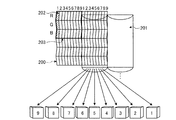
図3は、9視差画像により立体表示を行なう立体表示モニタの一例を説明するための図である。図3に示す立体表示モニタには、液晶パネル等の平面状の表示面200の前面に、光線制御子が配置される。例えば、図3に示す立体表示モニタには、光線制御子として、光学開口が垂直方向に延びる垂直レンチキュラーシート201が表示面200の前面に貼り付けられている。
FIG. 3 is a diagram for explaining an example of a stereoscopic display monitor that performs stereoscopic display using nine parallax images. In the stereoscopic display monitor shown in FIG. 3, a light beam controller is arranged on the front surface of a
表示面200には、図3に示すように、縦横比が3:1であり、縦方向にサブ画素である赤(R)、緑(G)、青(B)の3つが配置された画素202がマトリクス状に配置される。図3に示す立体表示モニタは、9つの画像により構成される9視差画像を、所定フォーマット(例えば格子状)に配置した中間画像に変換したうえで、表示面200に出力する。すなわち、図3に示す立体表示モニタは、9視差画像にて同一位置にある9つの画素それぞれを、9列の画素202に割り振って出力させる。9列の画素202は、視点位置の異なる9つの画像を同時に表示する単位画素群203となる。
As shown in FIG. 3, the
表示面200において単位画素群203として同時に出力された9視差画像は、例えば、LED(Light Emitting Diode)バックライトにより平行光として放射され、更に、垂直レンチキュラーシート201により、多方向に放射される。9視差画像の各画素の光が多方向に放射されることにより、観察者の右目及び左目に入射する光は、観察者の位置(視点の位置)に連動して変化する。すなわち、観察者の見る角度により、右目に入射する視差画像と左目に入射する視差画像とは、視差角が異なる。これにより、観察者は、例えば、図3に示す9つの位置それぞれにおいて、撮影対象を立体的に視認できる。また、観察者は、例えば、図3に示す「5」の位置において、撮影対象に対して正対した状態で立体的に視認できるとともに、図3に示す「5」以外それぞれの位置において、撮影対象の向きを変化させた状態で立体的に視認できる。なお、図3に示す立体表示モニタは、あくまでも一例である。9視差画像を表示する立体表示モニタは、図3に示すように、「RRR・・・、GGG・・・、BBB・・・」の横ストライプ液晶である場合であっても良いし、「RGBRGB・・・」の縦ストライプ液晶である場合であっても良い。また、図3に示す立体表示モニタは、図3に示すように、レンチキュラーシートが垂直となる縦レンズ方式である場合であっても良いし、レンチキュラーシートが斜めとなる斜めレンズ方式である場合であっても良い。
The nine parallax images simultaneously output as the
ここまで、第1の実施形態に係る画像処理システム1の構成例について簡単に説明した。なお、上述した画像処理システム1は、PACSが導入されている場合にその適用が限られるものではない。例えば、画像処理システム1は、医用画像が添付された電子カルテを管理する電子カルテシステムが導入されている場合にも、同様に適用される。この場合、画像保管装置120は、電子カルテを保管するデータベースである。また、例えば、画像処理システム1は、HIS(Hospital Information System)、RIS(Radiology Information System)が導入されている場合にも、同様に適用される。また、画像処理システム1は、上述した構成例に限られるものではない。各装置が有する機能やその分担は、運用の形態に応じて適宜変更されてよい。
So far, the configuration example of the
次に、第1の実施形態に係るワークステーションの構成例について図4を用いて説明する。図4は、第1の実施形態に係るワークステーションの構成例を説明するための図である。なお、以下において、「視差画像群」とは、ボリュームデータに対してボリュームレンダリング処理を行なうことで生成された立体視用の画像群のことである。また、「視差画像」とは、「視差画像群」を構成する個々の画像のことである。すなわち、「視差画像群」は、視点位置が異なる複数の「視差画像」から構成される。 Next, a configuration example of the workstation according to the first embodiment will be described with reference to FIG. FIG. 4 is a diagram for explaining a configuration example of the workstation according to the first embodiment. In the following description, the “parallax image group” is a group of stereoscopic images generated by performing volume rendering processing on volume data. Further, the “parallax image” is an individual image constituting the “parallax image group”. That is, the “parallax image group” includes a plurality of “parallax images” having different viewpoint positions.
第1の実施形態に係るワークステーション130は、画像処理等に適した高性能なコンピュータであり、図4に示すように、入力部131と、表示部132と、通信部133と、記憶部134と、制御部135と、レンダリング処理部136と、検出部137とを有する。なお、以下では、ワークステーション130が画像処理等に適した高性能なコンピュータである場合を用いて説明するが、これに限定されるものではなく、任意の情報処理装置であって良い。例えば、任意のパーソナルコンピュータであっても良い。
The
入力部131は、マウス、キーボード、トラックボール等であり、ワークステーション130に対する各種操作の入力を操作者から受け付ける。具体的には、第1の実施形態に係る入力部131は、レンダリング処理の対象となるボリュームデータを画像保管装置120から取得するための情報の入力を受け付ける。例えば、入力部131は、患者ID、検査ID、装置ID、シリーズID等の入力を受け付ける。また、第1の実施形態に係る入力部131は、レンダリング処理に関する条件(以下、レンダリング条件)の入力を受け付ける。
The input unit 131 is a mouse, a keyboard, a trackball, or the like, and receives input of various operations on the
表示部132は、立体表示モニタとしての液晶パネル等であり、各種情報を表示する。具体的には、第1の実施形態に係る表示部132は、操作者から各種操作を受け付けるためのGUI(Graphical User Interface)や、視差画像群等を表示する。通信部133は、NIC(Network Interface Card)等であり、他の装置との間で通信を行う。より具体的には、表示部132は、視差画像群を表示することで立体視可能に表示対象物の画像を表示するものであり、かつ、観察方向によって異なる視差画像が見えるように表示する。
The
記憶部134は、ハードディスク、半導体メモリ素子等であり、各種情報を記憶する。具体的には、第1の実施形態に係る記憶部134は、通信部133を介して画像保管装置120から取得したボリュームデータを記憶する。また、第1の実施形態に係る記憶部134は、レンダリング処理中のボリュームデータや、レンダリング処理により生成された視差画像群、及び、2次元表示用の画像等を記憶する。
The
制御部135は、CPU(Central Processing Unit)やMPU(Micro Processing Unit)等の電子回路、ASIC(Application Specific Integrated Circuit)やFPGA(Field Programmable Gate Array)等の集積回路であり、ワークステーション130の全体制御を行なう。
The
例えば、第1の実施形態に係る制御部135は、表示部132に対するGUIの表示や視差画像群の表示を制御する。また、例えば、制御部135は、画像保管装置120との間で通信部133を介して行なわれるボリュームデータや視差画像群の送受信を制御する。また、例えば、制御部135は、レンダリング処理部136によるレンダリング処理を制御する。また、例えば、制御部135は、ボリュームデータの記憶部134からの読み込みや、視差画像群の記憶部134への格納を制御する。
For example, the
レンダリング処理部136は、制御部135による制御の下、画像保管装置120から取得したボリュームデータに対して種々のレンダリング処理を行ない、視差画像群を生成する。なお、レンダリング処理部136の処理については、後に詳述する。
The
検出部137は、表示部132に対する視差画像の観察者の位置を検出する。具体的には、検出部137は、表示部132に対する観察者の立ち位置、観察者の顔の位置、観察者の視線位置などを検出する。検出部137としては、例えば、カメラを用いたモーショントラッキング装置や、光学式又は磁気式の位置センサーや、機械式のモーションキャプチャシステムなどである。なお、第1に実施形態では、検出部137として、カメラを用いたモーショントラッキング装置を利用する場合について説明するが、その説明については、後述する。
The detection unit 137 detects the position of the observer of the parallax image with respect to the
レンダリング処理部136は、制御部135による制御の下、画像保管装置120から取得したボリュームデータに対して種々のレンダリング処理を行ない、視差画像群を生成する。具体的には、第1の実施形態に係るレンダリング処理部136は、記憶部134からボリュームデータを読み込み、このボリュームデータに対して、まず前処理を行なう。次に、レンダリング処理部136は、前処理後のボリュームデータに対してボリュームレンダリング処理を行ない、視差画像群を生成する。続いて、レンダリング処理部136は、各種情報(目盛り、患者名、検査項目等)が描出された2次元画像を生成し、これを視差画像群それぞれに対して重畳することで、出力用の2次元画像を生成する。そして、レンダリング処理部136は、生成した視差画像群や出力用の2次元画像を記憶部134に格納する。なお、第1の実施形態において、レンダリング処理とは、ボリュームデータに対して行なう画像処理全体のことであり、ボリュームレンダリング処理とは、レンダリング処理の内、3次元の情報を反映した2次元画像を生成する処理のことである。レンダリング処理により生成される医用画像とは、例えば、視差画像が該当する。
The
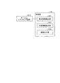
図5は、図4に示すレンダリング処理部の構成例を説明するための図である。図5に示すように、レンダリング処理部136は、前処理部1361と、3次元画像処理部1362と、2次元画像処理部1363とを有する。前処理部1361が、ボリュームデータに対する前処理を行い、3次元画像処理部1362が、前処理後のボリュームデータから視差画像群を生成し、2次元画像処理部1363が、視差画像群に各種情報が重畳された出力用の2次元画像を生成する。以下、各部を順に説明する。
FIG. 5 is a diagram for explaining a configuration example of the rendering processing unit shown in FIG. As illustrated in FIG. 5, the
前処理部1361は、ボリュームデータに対してレンダリング処理を行なう際に、種々の前処理を行なう処理部であり、画像補正処理部1361aと、3次元物体フュージョン部1361eと、3次元物体表示領域設定部1361fとを有する。
The
画像補正処理部1361aは、2種類のボリュームデータを1つのボリュームデータとして処理する際に画像補正処理を行なう処理部であり、図5に示すように、歪み補正処理部1361b、体動補正処理部1361c及び画像間位置合わせ処理部1361dを有する。例えば、画像補正処理部1361aは、PET−CT装置により生成されたPET画像のボリュームデータとX線CT画像のボリュームデータとを1つのボリュームデータとして処理する際に画像補正処理を行なう。或いは、画像補正処理部1361aは、MRI装置により生成されたT1強調画像のボリュームデータとT2強調画像のボリュームデータとを1つのボリュームデータとして処理する際に画像補正処理を行なう。 The image correction processing unit 1361a is a processing unit that performs image correction processing when processing two types of volume data as one volume data, and as shown in FIG. 5, a distortion correction processing unit 1361b, a body motion correction processing unit, 1361c and an inter-image registration processing unit 1361d. For example, the image correction processing unit 1361a performs image correction processing when processing volume data of a PET image generated by a PET-CT apparatus and volume data of an X-ray CT image as one volume data. Alternatively, the image correction processing unit 1361a performs image correction processing when processing the volume data of the T1-weighted image and the volume data of the T2-weighted image generated by the MRI apparatus as one volume data.
また、歪み補正処理部1361bは、個々のボリュームデータにおいて、医用画像診断装置110によるデータ収集時の収集条件に起因するデータの歪みを補正する。また、体動補正処理部1361cは、個々のボリュームデータを生成するために用いられたデータの収集時期における被検体の体動に起因する移動を補正する。また、画像間位置合わせ処理部1361dは、歪み補正処理部1361b及び体動補正処理部1361cによる補正処理が行なわれた2つのボリュームデータ間で、例えば、相互相関法等を用いた位置合わせ(Registration)を行なう。
In addition, the distortion correction processing unit 1361b corrects the data distortion caused by the collection conditions at the time of data collection by the medical image
3次元物体フュージョン部1363eは、画像間位置合わせ処理部1361dにより位置合わせが行なわれた複数のボリュームデータをフュージョンさせる。なお、画像補正処理部1361a及び3次元物体フュージョン部1361eの処理は、単一のボリュームデータに対してレンダリング処理を行なう場合、省略される。
The three-dimensional object fusion unit 1363e fuses a plurality of volume data that has been aligned by the inter-image registration processing unit 1361d. Note that the processing of the image correction processing unit 1361a and the three-dimensional
3次元物体表示領域設定部1361fは、操作者により指定された表示対象臓器に対応する表示領域を設定する処理部であり、セグメンテーション処理部1361gを有する。セグメンテーション処理部1361gは、操作者により指定された心臓、肺、血管等の臓器を、例えば、ボリュームデータの画素値(ボクセル値)に基づく領域拡張法により抽出する処理部である。
The three-dimensional object display
なお、セグメンテーション処理部1361gは、操作者により表示対象臓器が指定されなかった場合、セグメンテーション処理を行なわない。また、セグメンテーション処理部1361gは、操作者により表示対象臓器が複数指定された場合、該当する複数の臓器を抽出する。また、セグメンテーション処理部1361gの処理は、レンダリング画像を参照した操作者の微調整要求により再度実行される場合もある。 Note that the segmentation processing unit 1361g does not perform the segmentation process when the display target organ is not designated by the operator. The segmentation processing unit 1361g extracts a plurality of corresponding organs when a plurality of display target organs are designated by the operator. Further, the processing of the segmentation processing unit 1361g may be executed again in response to an operator fine adjustment request referring to the rendered image.
3次元画像処理部1362は、前処理部1361が処理を行なった前処理後のボリュームデータに対してボリュームレンダリング処理を行なう。ボリュームレンダリング処理を行なう処理部として、3次元画像処理部1362は、投影方法設定部1362aと、3次元幾何変換処理部1362bと、3次元物体アピアランス処理部1362fと、3次元仮想空間レンダリング部1362kとを有する。
The 3D
投影方法設定部1362aは、視差画像群を生成するための投影方法を決定する。例えば、投影方法設定部1362aは、ボリュームレンダリング処理を平行投影法により実行するか、透視投影法により実行するかを決定する。 The projection method setting unit 1362a determines a projection method for generating a parallax image group. For example, the projection method setting unit 1362a determines whether to execute the volume rendering process by the parallel projection method or the perspective projection method.
3次元幾何変換処理部1362bは、ボリュームレンダリング処理が実行されるボリュームデータを3次元幾何学的に変換するための情報を決定する処理部であり、平行移動処理部1362c、回転処理部1362d及び拡大縮小処理部1362eを有する。平行移動処理部1362cは、ボリュームレンダリング処理を行なう際の視点位置が平行移動された場合に、ボリュームデータを平行移動させる移動量を決定する処理部であり、回転処理部1362dは、ボリュームレンダリング処理を行なう際の視点位置が回転移動された場合に、ボリュームデータを回転移動させる移動量を決定する処理部である。また、拡大縮小処理部1362eは、視差画像群の拡大や縮小が要求された場合に、ボリュームデータの拡大率や縮小率を決定する処理部である。
The three-dimensional geometric transformation processing unit 1362b is a processing unit that determines information for transforming volume data on which volume rendering processing is performed into a three-dimensional geometrical structure. The three-dimensional geometric transformation processing unit 1362b includes a parallel movement processing unit 1362c, a rotation processing unit 1362d, and an enlargement unit. A
3次元物体アピアランス処理部1362fは、3次元物体色彩処理部1362g、3次元物体不透明度処理部1362h、3次元物体材質処理部1362i及び3次元仮想空間光源処理部1362jを有する。3次元物体アピアランス処理部1362fは、これらの処理部により、例えば、操作者の要求に応じて、表示される視差画像群の表示状態を決定する処理を行なう。
The three-dimensional object
3次元物体色彩処理部1362gは、ボリュームデータにてセグメンテーションされた各領域に対して着色される色彩を決定する処理部である。3次元物体不透明度処理部1362hは、ボリュームデータにてセグメンテーションされた各領域を構成する各ボクセルの不透過度(Opacity)を決定する処理部である。なお、ボリュームデータにおいて不透過度が「100%」とされた領域の後方の領域は、視差画像群において描出されないこととなる。また、ボリュームデータにおいて不透過度が「0%」とされた領域は、視差画像群において描出されないこととなる。
The three-dimensional object color processing unit 1362g is a processing unit that determines a color to be colored for each region segmented by the volume data. The three-dimensional object
3次元物体材質処理部1362iは、ボリュームデータにてセグメンテーションされた各領域の材質を決定することで、この領域が描出される際の質感を調整する処理部である。3次元仮想空間光源処理部1362jは、ボリュームデータに対してボリュームレンダリング処理を行なう際に、3次元仮想空間に設置する仮想光源の位置や、仮想光源の種類を決定する処理部である。仮想光源の種類としては、無限遠から平行な光線を照射する光源や、視点から放射状の光線を照射する光源等が挙げられる。
The three-dimensional object
3次元仮想空間レンダリング部1362kは、ボリュームデータに対してボリュームレンダリング処理を行ない、視差画像群を生成する。また、3次元仮想空間レンダリング部1362kは、ボリュームレンダリング処理を行なう際、必要に応じて、投影方法設定部1362a、3次元幾何変換処理部1362b、3次元物体アピアランス処理部1362fにより決定された各種情報を用いる。
The three-dimensional virtual space rendering unit 1362k performs volume rendering processing on the volume data to generate a parallax image group. The three-dimensional virtual space rendering unit 1362k performs various types of information determined by the projection method setting unit 1362a, the three-dimensional geometric transformation processing unit 1362b, and the three-dimensional object
ここで、3次元仮想空間レンダリング部1362kによるボリュームレンダリング処理は、レンダリング条件に従って行なわれることになる。例えば、レンダリング条件は、「平行投影法」又は「透視投影法」である。また、例えば、レンダリング条件は、「基準の視点位置及び視差角」である。また、例えば、レンダリング条件は、「視点位置の平行移動」、「視点位置の回転移動」、「視差画像群の拡大」、「視差画像群の縮小」である。また、例えば、レンダリング条件は、「着色される色彩」、「透過度」、「質感」、「仮想光源の位置」、「仮想光源の種類」である。このようなレンダリング条件は、入力部131を介して操作者から受け付ける場合や、初期設定される場合が考えられる。いずれの場合も、3次元仮想空間レンダリング部1362kは、制御部135からレンダリング条件を受け付け、このレンダリング条件に従って、ボリュームデータに対するボリュームレンダリング処理を行なう。また、このとき、上述した投影方法設定部1362a、3次元幾何変換処理部1362b、3次元物体アピアランス処理部1362fが、このレンダリング条件に従って必要な各種情報を決定するので、3次元仮想空間レンダリング部1362kは、決定されたこれらの各種情報を用いて視差画像群を生成する。
Here, the volume rendering process by the three-dimensional virtual space rendering unit 1362k is performed according to the rendering conditions. For example, the rendering condition is “parallel projection method” or “perspective projection method”. For example, the rendering condition is “reference viewpoint position and parallax angle”. Further, for example, the rendering conditions are “translation of viewpoint position”, “rotational movement of viewpoint position”, “enlargement of parallax image group”, and “reduction of parallax image group”. Further, for example, the rendering conditions are “color to be colored”, “transparency”, “texture”, “position of virtual light source”, and “type of virtual light source”. Such a rendering condition may be accepted from the operator via the input unit 131 or may be initially set. In any case, the three-dimensional virtual space rendering unit 1362k receives a rendering condition from the
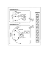
図6は、第1の実施形態に係るボリュームレンダリング処理の一例を説明するための図である。例えば、3次元仮想空間レンダリング部1362kが、図6の「9視差画像生成方式(1)」に示すように、レンダリング条件として、平行投影法を受け付け、更に、基準の視点位置(5)と視差角「1度」とを受け付けたとする。かかる場合、3次元仮想空間レンダリング部1362kは、視差角が「1度」おきとなるように、視点の位置を(1)〜(9)に平行移動して、平行投影法により視差角(視線方向間の角度)が1度ずつ異なる9つの視差画像を生成する。なお、平行投影法を行なう場合、3次元仮想空間レンダリング部1362kは、視線方向に沿って無限遠から平行な光線を照射する光源を設定する。 FIG. 6 is a diagram for explaining an example of volume rendering processing according to the first embodiment. For example, as shown in “9 parallax image generation method (1)” in FIG. 6, the three-dimensional virtual space rendering unit 1362k accepts the parallel projection method as a rendering condition, and further, the reference viewpoint position (5) and the parallax. Assume that the angle “1 degree” is received. In such a case, the three-dimensional virtual space rendering unit 1362k translates the position of the viewpoint from (1) to (9) so that the parallax angle is "1 degree", and the parallax angle (line of sight) is obtained by the parallel projection method. Nine parallax images with different degrees between directions are generated. When performing the parallel projection method, the three-dimensional virtual space rendering unit 1362k sets a light source that emits parallel light rays from infinity along the line-of-sight direction.
或いは、3次元仮想空間レンダリング部1362kが、図6の「9視差画像生成方式(2)」に示すように、レンダリング条件として、透視投影法を受け付け、更に、基準の視点位置(5)と視差角「1度」とを受け付けたとする。かかる場合、3次元仮想空間レンダリング部1362kは、ボリュームデータの中心(重心)を中心に視差角が「1度」おきとなるように、視点の位置を(1)〜(9)に回転移動して、透視投影法により視差角が1度ずつ異なる9つの視差画像を生成する。なお、透視投影法を行なう場合、3次元仮想空間レンダリング部1362kは、視線方向を中心に光を3次元的に放射状に照射する点光源や面光源を各視点にて設定する。また、透視投影法を行なう場合、レンダリング条件によっては、視点(1)〜(9)は、平行移動される場合であってもよい。 Alternatively, as shown in “9-parallax image generation method (2)” in FIG. 6, the three-dimensional virtual space rendering unit 1362k accepts a perspective projection method as a rendering condition, and further, the reference viewpoint position (5) and the parallax Assume that the angle “1 degree” is received. In such a case, the three-dimensional virtual space rendering unit 1362k rotates and moves the viewpoint position from (1) to (9) so that the parallax angle is every "1 degree" around the center (center of gravity) of the volume data. Thus, nine parallax images having different parallax angles by 1 degree are generated by the perspective projection method. When performing the perspective projection method, the three-dimensional virtual space rendering unit 1362k sets a point light source or a surface light source that radiates light three-dimensionally radially around the line-of-sight direction at each viewpoint. When performing the perspective projection method, the viewpoints (1) to (9) may be translated depending on rendering conditions.
なお、3次元仮想空間レンダリング部1362kは、表示されるボリュームレンダリング画像の縦方向に対しては、視線方向を中心に光を2次元的に放射状に照射し、表示されるボリュームレンダリング画像の横方向に対しては、視線方向に沿って無限遠から平行な光線を照射する光源を設定することで、平行投影法と透視投影法とを併用したボリュームレンダリング処理を行なってもよい。 Note that the three-dimensional virtual space rendering unit 1362k radiates light two-dimensionally radially around the line-of-sight direction with respect to the vertical direction of the displayed volume rendered image, and the horizontal direction of the displayed volume rendered image. On the other hand, volume rendering processing using both the parallel projection method and the perspective projection method may be performed by setting a light source that irradiates parallel light rays from infinity along the viewing direction.
このようにして生成された9つの視差画像が、視差画像群である。第1の実施形態において、9つの視差画像は、例えば制御部135により所定フォーマット(例えば格子状)に配置した中間画像に変換され、立体表示モニタとしての表示部132に出力される。すると、ワークステーション130の操作者は、立体表示モニタに表示された立体視可能な医用画像を確認しながら、視差画像群生成のための操作を行なうことができる。
The nine parallax images generated in this way are a parallax image group. In the first embodiment, the nine parallax images are converted into intermediate images arranged in a predetermined format (for example, a lattice shape) by the
なお、図6の例では、レンダリング条件として、投影方法、基準の視点位置及び視差角を受け付けた場合を説明したが、レンダリング条件として、他の条件を受け付けた場合も同様に、3次元仮想空間レンダリング部1362kは、それぞれのレンダリング条件を反映しつつ、視差画像群を生成する。 In the example of FIG. 6, the case where the projection method, the reference viewpoint position, and the parallax angle are received as the rendering conditions has been described. However, the three-dimensional virtual space is similarly applied when other conditions are received as the rendering conditions. The rendering unit 1362k generates a parallax image group while reflecting each rendering condition.
また、3次元仮想空間レンダリング部1362kは、ボリュームレンダリングだけでなく、任意の平面(例えば、アキシャル面、サジタル面、コロナル面など)の平面画像を再構成する。例えば、3次元仮想空間レンダリング部1362kは、断面再構成法(MPR:Multi Planer Reconstruction)を行なってボリュームデータからMPR画像を再構成する。なお、3次元仮想空間レンダリング部1362kは、「Curved MPR」を行なう機能や、「Intensity Projection」を行なう機能も有する。 The three-dimensional virtual space rendering unit 1362k reconstructs not only volume rendering but also a planar image of an arbitrary plane (for example, an axial plane, a sagittal plane, a coronal plane, etc.). For example, the three-dimensional virtual space rendering unit 1362k performs a cross-section reconstruction method (MPR: Multi Planer Reconstruction) to reconstruct an MPR image from volume data. The three-dimensional virtual space rendering unit 1362k also has a function of performing “Curved MPR” and a function of performing “Intensity Projection”.
続いて、3次元画像処理部1362がボリュームデータから生成した視差画像群は、アンダーレイ(Underlay)とされる。そして、各種情報(目盛り、患者名、検査項目等)が描出されたオーバーレイ(Overlay)がアンダーレイに対して重畳されることで、出力用の2次元画像とされる。2次元画像処理部1363は、オーバーレイ及びアンダーレイに対して画像処理を行なうことで、出力用の2次元画像を生成する処理部であり、図5に示すように、2次元物体描画部1363a、2次元幾何変換処理部1363b及び輝度調整部1363cを有する。例えば、2次元画像処理部1363は、出力用の2次元画像の生成処理に要する負荷を軽減するために、9枚の視差画像(アンダーレイ)のそれぞれに対して1枚のオーバーレイを重畳することで、出力用の2次元画像を9枚、生成する。
Subsequently, the parallax image group generated from the volume data by the three-dimensional
2次元物体描画部1363aは、オーバーレイに描出される各種情報を描画する処理部であり、2次元幾何変換処理部1363bは、オーバーレイに描出される各種情報の位置を平行移動処理又は回転移動処理したり、オーバーレイに描出される各種情報の拡大処理又は縮小処理したりする処理部である。
The two-dimensional
また、輝度調整部1363cは、輝度変換処理を行なう処理部であり、例えば、出力先の立体表示モニタの諧調や、ウィンドウ幅(WW:Window Width)、ウィンドウレベル(WL:Window Level)等の画像処理用のパラメータに応じて、オーバーレイ及びアンダーレイの輝度を調整する処理部である。
The
このようにして生成された出力用の2次元画像は、例えば制御部135により一旦記憶部134に格納され、その後、通信部133を介して画像保管装置120に送信される。例えば、端末装置140が、画像保管装置120からこの出力用の2次元画像を取得し、所定フォーマット(例えば格子状)に配置した中間画像に変換した上で立体表示モニタに表示すると、観察者である医師や検査技師は、各種情報(目盛り、患者名、検査項目等)が描出された状態で、立体視可能な医用画像を閲覧することができる。
The output two-dimensional image generated in this way is temporarily stored in the
以上、第1の実施形態に係る画像処理システム1及びワークステーション130の構成について説明した。かかる構成のもと、第1の実施形態に係るワークステーション130は、以下、詳細に説明する制御部135の処理により、操作者によって観察された画像を容易に出力することが可能となるように構成されている。具体的には、第1の実施形態に係るワークステーション130は、表示部132に表示された視差画像の情報と、観察者の位置情報とに基づいて、表示されている視差画像に対する観察者の相対位置を算出し、算出した相対位置に応じた画像を表示する。
The configurations of the
図7は、第1の実施形態に係る制御部135の構成例を説明するための図である。図7に示すように、制御部135は、視点情報検出部1351と、位置情報算出部1352と、画像出力部1353とを有し、モーショントラッキング装置1371と接続されている。モーショントラッキング装置1371は、表示部132に対する観察者の位置を検出する。具体的には、モーショントラッキング装置1371は、観察者を撮影するためのカメラと、カメラの向きを変更させるための駆動装置(例えば、モーターなど)を有し、視点情報検出部1351による制御の元、観察者を撮影する。なお、モーショントラッキング装置1371は、図4に示す検出部137の一例である。
FIG. 7 is a diagram for explaining a configuration example of the
視点情報検出部1351は、観察者による表示部132の観察方向を検出する。換言すると、視点情報検出部1351は、表示部132に対する表示対象物の観察者の位置を検出する。具体的には、視点情報検出部1351は、モーショントラッキング装置1371を制御して観察者を撮影させ、表示部132に対する観察者の位置を検出する。図8は、第1の実施形態に係る視点情報検出部1351による観察者の位置の情報を取得する処理の一例を説明するための図である。
The viewpoint
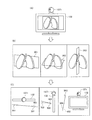
ここで、多視差(例えば、9視差)で描出した三次元の医用画像を用いた読影について、図8の(A)を用いて説明する。多視差で描出した視差画像を表示することで3次元として認識される医用画像の場合には、観察者の視点移動に合わせて観察される映像も変化する運動視差による立体視が可能である。例えば、図8の(A)に示すように、観察者が表示部132に表示された「肺」の画像を異なる視点から観察すると、その位置に応じて異なった部分を観察することが可能である。
Here, interpretation using a three-dimensional medical image drawn with multiple parallaxes (for example, 9 parallaxes) will be described with reference to FIG. In the case of a medical image that is recognized as a three-dimensional image by displaying a parallax image drawn with multiple parallaxes, a stereoscopic view with motion parallax that changes the video observed in accordance with the viewpoint movement of the observer is possible. For example, as shown in FIG. 8A, when the observer observes the “lung” image displayed on the
そこで、例えば、図8の(B)に示すように、表示部132によって視差画像が表示され、観察者が表示部132の左側に位置し、保存や印刷操作を実行すると、視点情報検出部1351は、モーショントラッキング装置1371を制御して、観察者の位置を検出する。一例を説明すると、視点情報検出部1351は、観察者から保存又は印刷の操作を受付けると、モーショントラッキング装置1371のモーターを駆動させることで撮影範囲を変えながら、表示部132の前面をカメラにより撮影させる。そして、視点情報検出部1351は、カメラによって撮影された画像に対して、顔認識のパターンマッチングを行い、観察者の顔が描出された画像を特定する。
Therefore, for example, as illustrated in FIG. 8B, when the parallax image is displayed on the
さらに、視点情報検出部1351は、観察者の顔が描出された画像を特定すると、当該画像が撮影された際のカメラの向きに基づいて、表示部132に対する観察者の位置を検出する。図9は、第1の実施形態に係る視点情報検出部1351による検出処理の一例を説明するための図である。ここで、図9においては、観察者及び表示部132の上面図を示す。
Further, when the viewpoint
例えば、視点情報検出部1351は、図9に示すように、表示部132のモニタの面と、観察者の顔が描出された画像が撮影された際のモーショントラッキング装置1371のカメラの向きとからなる角度「45°」を、表示部132に対する観察者の位置として検出する。そして、視点情報検出部1351は、検出した観察者の位置「角度:45°」を視点情報として位置情報算出部1352に出力する。
For example, as illustrated in FIG. 9, the viewpoint
図7に戻って、位置情報算出部1352は、表示部132における表示対象物の表示設定に関する情報に基づいて、視点情報検出部1351によって検出された観察者の位置と表示対象物との相対位置を算出する。言い換えると、位置情報算出部1352は、観察者の位置から観察される表示対象物の位置を算出する。具体的には、位置情報算出部1352は、まず、観察者によって観察された視差画像の表示設定から表示対象物がどのように表示されたかを示す情報を取得する。図10は、第1の実施形態に係る位置情報算出部1352による処理の一例を説明するための図である。
Returning to FIG. 7, the position information calculation unit 1352 is based on the information related to the display setting of the display object in the
例えば、位置情報算出部1352は、図10の(A)に示すように、表示部132に表示された「肺」の画像の表示設定の情報(以下、表示パラメータと記す)を取得する。一例を挙げると、位置情報算出部1352は、図10の(B)に示すように、「肺」のボリュームデータにおける直交三断面301、直交三断面302及び直交三断面303の情報を取得する。そして、位置情報算出部1352は、表示部132に表示された「肺」の画像の直交三断面301、直交三断面302及び直交三断面303が表示部132に対してどのような位置で表示されているかを算出する。
For example, as illustrated in FIG. 10A, the position information calculation unit 1352 acquires display setting information (hereinafter referred to as a display parameter) of the “lung” image displayed on the
例えば、位置情報算出部1352は、図10の(C)に示すように、表示部132の表示面に対して横方向に平行な直線401と直交三断面301とからなる角度501を算出する。また、位置情報算出部1352は、表示部132の表示面に対して垂直な直線402と直交三断面302とからなる角度502を算出する。また、位置情報算出部1352は、表示部132の表示面に対して縦方向に平行な直線403と直交三断面503とからなる角度503を算出する。さらに、位置情報算出部1352は、「肺」を描出する視差画像の視差角や、体軸方向などの情報を表示パラメータとして取得する。
For example, as illustrated in FIG. 10C, the position information calculation unit 1352 calculates an
そして、位置情報算出部1352は、取得した表示パラメータと、視点情報検出部1351によって検出された視点情報とから、表示部120に表示された「肺」と観察者との相対位置を算出する。すなわち、位置情報算出部1352は、表示パラメータと視点情報とから、観察者が入力部110を介して入力操作を実行した際の位置から観察されうる表示対象物の位置を算出する。例えば、位置情報算出部1352は、図6に示す視点(1)から観察した場合の視差画像を特定するための情報を算出する。図11は、第1の実施形態に係る位置情報算出部1352による相対位置の算出処理の一例を説明するための図である。
Then, the position information calculation unit 1352 calculates the relative position between the “lung” displayed on the
例えば、位置情報算出部1352は、図11に示すように、ボリューム中心(あるいは、重心)を原点とした3軸(x軸、y軸、z軸)からなる直交座標を設定する。そして、位置情報算出部1352は、表示パラメータと視点情報とを用いて、観察者が観察した視差画像をボリュームレンダリング処理にて生成する際の視点位置の座標を相対位置として算出する。 For example, as shown in FIG. 11, the position information calculation unit 1352 sets orthogonal coordinates including three axes (x axis, y axis, z axis) with the volume center (or centroid) as the origin. Then, the position information calculation unit 1352 uses the display parameters and the viewpoint information to calculate the coordinates of the viewpoint position when the parallax image observed by the observer is generated by the volume rendering process as a relative position.
ここで、位置情報算出部1352は、取得した表示パラメータの情報と、視点情報検出部1351によって検出された視点情報と、算出した相対位置とを患者情報に対応付けた相対位置情報を記憶部134に格納する。図12は、第1の実施形態に係る位置情報算出部1352によって格納される相対位置情報の一例を示す図である。例えば、位置情報算出部1352は、図11に示すように、「患者ID:1」に対して、「診断部位:肺」と、表示パラメータ「視差角:5、直交三断面301:3、直交三断面302:1、直交三断面303:1、体軸方向:上方」と、「視点情報:45」と、「相対位置:(a、b、c)」とを対応付けた相対位置情報を記憶部134に格納する。
Here, the position information calculation unit 1352 stores the relative position information in which the acquired display parameter information, the viewpoint information detected by the viewpoint
すなわち、上記した相対位置情報は、「患者ID:1」の患者に対して「肺」の画像診断が実行された際の画像は、「視差角」が「5°」で生成された視差画像であり、「直交三断面301」、「直交三断面302」、「直交三断面303」が、表示部132に対して、ぞれぞれ「3°」、「1°」、「1°」の角度であり、「体軸方向」が上方になるように表示された「肺」を、観察者が「視点情報:45°」の位置で観察した画像であることを示す。そして、上記した相対位置情報は、観察者によって観察された視差画像は、「相対位置:(a,b,c)」からボリュームレンダリング処理が実行された画像であることを示す。
That is, the above-described relative position information indicates that an image obtained when the image diagnosis of “lung” is performed on the patient with “patient ID: 1” is a parallax image generated with a “parallax angle” of “5 °”. The “three
図7に戻って、画像出力部1353は、観察方向に基づいて、視差画像群の中から画像を選択して出力する。具体的には、画像出力部1353は、位置情報算出部1352によって格納された相対位置に関する情報に基づいて、観察者の位置に正対する向きの表示対象物を出力するように制御する。例えば、画像出力部1353は、記憶部134によって記憶された相対位置情報に含まれる「相対位置」の座標が表示部132の表示面の中心になるように出力させる。図13は、第1の実施形態に係る画像出力部1353による処理の一例を説明するための図である。
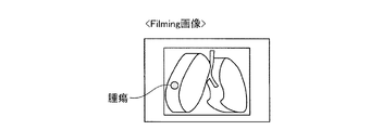
Returning to FIG. 7, the
例えば、画像出力部1353は、図13に示すように、印刷操作を受付けた際のFilming画像として、「座標:(a,b,c)」でボリュームレンダリング処理が実行された視差画像が表示部132の中心になるように配置された画像を出力する。その結果、画像出力部1353は、図13に示すように、観察者によって観察された腫瘍が描出された画像を出力させることとなる。
For example, as illustrated in FIG. 13, the
そして、画像出力部1353は、後に、他の観察者によって「患者ID:1」の「診断部位:肺」の画像の表示要求を受付けた場合には、記憶部134によって記憶された相対位置情報を参照して画像を表示させる。従って、第1の実施形態に係るワークステーションは、観察者によって観察された画像を容易に出力することを可能にする。
When the
ここで、画像出力部1353は、単一の2次元の画像を出力する。また、画像出力部1353は、任意の数の視差画像を出力することで立体視可能な画像を出力する。具体的には、画像出力部1353は、位置情報算出部1352によって格納された相対位置に関する情報に基づいて、観察者の位置に正対する向きの表示対象物を、立体視可能な視差画像、単一視点からの2次元画像(例えば、ボリュームレンダリング画像や、MPR画像など)として出力するように制御する。例えば、画像出力部1353は、観察者の位置に正対する向きの表示対象物を、複数の視点からのレンダリング処理により視差画像として生成させ、生成させた視差画像を表示部132に表示させる。また、画像出力部1353は、観察者の位置に正対する向きの表示対象物を、単一方向からのボリュームレンダリング画像、或いは、MPR画像として生成させ、生成させた画像を表示部132に表示させる。
Here, the
上述した実施形態では、観察者によって観察された画像を表示したり、印刷したりする場合について説明した。しかしながら、開示の技術はこれに限定されるものではなく、例えば、観察者が保存操作を実行した場合に、観察者によって観察された画像を保存する場合であってもよい。 In the above-described embodiment, the case where an image observed by an observer is displayed or printed has been described. However, the disclosed technique is not limited to this, and may be, for example, a case where an image observed by an observer is stored when the observer performs a storage operation.
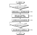
次に、図14を用いて、第1の実施形態に係るワークステーション130の処理について説明する。図14は、第1の実施形態に係るワークステーション130による処理の手順を示すフローチャートである。図14に示すように、第1の実施形態に係るワークステーション130においては、入力部110が入力操作を受付けると(ステップS101肯定)、モーショントラッキング装置1371が観察者を検出し、視点情報検出部1351が、表示部120に対する観察者の位置を示す情報である視点情報を取得する(ステップS102)。
Next, processing of the
そして、位置情報算出部1352が、表示部132に表示された視差画像の表示パラメータを取得し、取得した表示パラメータと視点情報とから、視差画像と観察者との相対的な位置を示す相対位置を算出して記憶部134に保存する(ステップS103)。その後、画像出力部1353が、記憶部134によって記憶された相対位置に関する情報を参照して、入力操作に応じた出力処理を実行する(ステップS104)。
Then, the position information calculation unit 1352 acquires the display parameter of the parallax image displayed on the
そして、入力部110が新たな出力要求を受付けると(ステップS105肯定)、画像出力部1353が、記憶部134によって記憶された相対位置に基づいた画像を出力させる(ステップS106)。なお、第1の実施形態に係るワークステーション130は、入力を介して操作が実行されるまで待機状態である(ステップS101否定、ステップS105否定)。
When the
上述したように、第1の実施形態によれば、表示部132は、視差画像群を表示することで立体視可能に表示対象物の画像を表示するものであり、かつ、観察方向によって異なる視差画像が見えるように表示する。視点情報検出部1351は、観察者による表示部132の観察方向を検出する。画像出力部1353は、観察方向に基づいて、視差画像群の中から画像を選択して出力する。従って、第1の実施形態に係るワークステーション130は、観察者によって観察された画像を容易に出力することを可能にする。
As described above, according to the first embodiment, the
また、第1の実施形態によれば、画像出力部1353は、単一の2次元の画像を出力する。従って、第1の実施形態に係るワークステーション130は、例えば、画像を出力するモニタの種類などに応じて2次元画像と立体視可能な3次元画像とを選択的に表示させることを可能にする。
According to the first embodiment, the
また、第1の実施形態によれば、画像出力部1353は、任意の数の視差画像を出力することで立体視可能な画像を出力する。従って、第1の実施形態に係るワークステーション130は、モニタごとに異なる表示可能な視差画像の数に柔軟に対応することを可能にする。
Further, according to the first embodiment, the
また、第1の実施形態によれば、位置情報算出部1352は、表示部132における表示対象物の表示設定に関する情報に基づいて、視点情報検出部1351によって検出された観察者の位置と表示対象物との相対位置を算出し、算出した相対位置に関する情報を記憶部134に格納する。画像出力部1353は、位置情報算出部1352によって格納された相対位置に関する情報に基づいて、観察者の位置に正対する向きの表示対象物を、立体視可能な視差画像群、単一視点からの2次元画像として出力する。従って、第1の実施形態に係るワークステーション130は、モニタの種類に関係なく、種々の情報処理装置に対して、観察者によって観察された画像を正確に表示することを可能にする。
Further, according to the first embodiment, the position information calculation unit 1352 is based on the information related to the display setting of the display object in the
また、第1の実施形態によれば、位置情報算出部1352は、相対位置に関する情報として、観察者の位置から観察される前記表示対象物の視点位置の座標を記憶部134に格納する。従って、第1の実施形態に係るワークステーション130は、記憶させる情報量を少なくすることを可能にする。
Further, according to the first embodiment, the position information calculation unit 1352 stores the coordinates of the viewpoint position of the display object observed from the observer's position in the
(第2の実施形態)
上述した第1の実施形態では相対位置の情報として視点位置の座標を保存する場合について説明した。第2の実施形態では、相対位置の情報として観察者から観察された画像そのものを保存する場合について説明する。
(Second Embodiment)
In the first embodiment described above, the case where the coordinates of the viewpoint position are stored as the relative position information has been described. In the second embodiment, a case will be described in which an image observed by an observer is stored as relative position information.
図15は、第2の実施形態に係る制御部135aの構成例を説明するための図である。図15に示すように、第2の実施形態に係る制御部135aは、第1に実施形態に係る制御部135と比較して、位置情報算出部1352aの処理内容が異なる。以下、これを中心に説明する。
FIG. 15 is a diagram for explaining a configuration example of the control unit 135a according to the second embodiment. As illustrated in FIG. 15, the control unit 135a according to the second embodiment differs from the
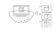
位置情報算出部1352aは、相対位置に関する情報として、観察者の位置から観察される表示対象物の領域の画像を記憶部134に格納する。具体的には、位置情報算出部1352aは、視点情報検出部1351によって検出された視点情報に対応する視差画像のデータを記憶部134に格納する。図16は、第2の実施形態に係る位置情報算出部1352aによる処理の一例を説明するための図である。図16においては、視点ごとの視差画像について示す。例えば、位置情報算出部1352aは、図16に示す視点ごとのボリュームレンダリング画像のデータから観察者の位置に対応する画像を抽出して、記憶部134に格納する。一例を挙げると、位置情報算出部1352aは、観察者が図16の(3)の方向に位置していた場合に、(3)に対応するボリュームレンダリング画像を患者IDなどに対応付けて記憶部134に格納する。
The position
画像出力部1353は、他の観察者から出力操作を受付けると、記憶部134に格納されている画像を読み出し、読み出した画像を出力させる。
When receiving an output operation from another observer, the
次に、図17を用いて、第2の実施形態に係るワークステーション130の処理について説明する。図17は、第2の実施形態に係るワークステーション130による処理の手順を示すフローチャートである。図17に示すように、第2の実施形態に係るワークステーション130においては、入力部110が入力操作を受付けると(ステップS201肯定)、モーショントラッキング装置1371が観察者を検出し、視点情報検出部1351が、表示部120に対する観察者の位置を示す情報である視点情報を取得する(ステップS202)。
Next, processing of the
そして、位置情報算出部1352aが、表示部132に表示された視差画像の表示パラメータを取得し、取得した表示パラメータと視点情報とから、視点情報に対応する画像を抽出して記憶部134に保存する(ステップS203)。その後、画像出力部1353が、記憶部134によって記憶された画像を読み出し、入力操作に応じた出力処理を実行する(ステップS204)。
Then, the position
そして、入力部110が新たな出力操作を受付けると(ステップS205肯定)、画像出力部1353が、出力操作を受付けた画像を記憶部134から読み出し、読み出した画像を出力させる(ステップS206)。なお、第2の実施形態に係るワークステーション130は、入力を介して操作が実行されるまで待機状態である(ステップS201否定、ステップS205否定)。
Then, when the
上述したように、第2の実施形態によれば、位置情報算出部1352aは、相対位置に関する情報として、観察者の位置から観察される表示対象物の領域の画像を記憶部134に格納する。従って、第2の実施形態に係るワークステーション130は、画像を出力する際に、再度、画像を生成することなく表示することができ、処理負荷を低減することを可能にする。
As described above, according to the second embodiment, the position
(第3の実施形態)
さて、これまで第1及び第2の実施形態について説明したが、上述した第1及び第2の実施形態以外にも、種々の異なる形態にて実施されてよいものである。
(Third embodiment)
Although the first and second embodiments have been described so far, the present invention may be implemented in various different forms other than the first and second embodiments described above.
上述した実施形態においては、ワークステーション130が、観察者の視点位置に応じた画像を表示する場合について説明した。しかしながら、開示の技術がこれに限定されるものではなく、例えば、医用画像診断装置110が観察者の視点位置に応じた画像を表示する場合であってもよい。また、医用画像診断装置110又はワークステーション130が観察者の視点位置に応じた画像や画像の座標を記憶部に格納し、端末装置140が、記憶部に記憶された情報に基づいて画像を表示する場合であってもよい。
In the above-described embodiment, the case where the
また、上述した実施形態においては、ワークステーション130は、画像保管装置120からボリュームデータを取得し、このボリュームデータから観察者の視点位置に応じた画像を生成して表示する場合について説明した。しかしながら、開示の技術はこれに限定されるものではなく、例えば、ワークステーション130は、医用画像診断装置110からボリュームデータを取得し、このボリュームデータから観察者の視点位置に応じた画像を生成して表示する場合であってもよい。
In the above-described embodiment, the case has been described in which the
上述した実施形態においては、観察者の位置を顔認識により検出する場合について説明した。しかしながら、開示の技術はこれに限定されるものではなく、例えば、観察者の視線情報から観察者の位置を検出する場合であってもよい。 In the above-described embodiment, the case where the position of the observer is detected by face recognition has been described. However, the disclosed technique is not limited to this, and may be, for example, a case where the position of the observer is detected from the line-of-sight information of the observer.
上述した実施形態においては、観察者の位置を表示部132の表示面を基準に算出する場合について説明した。しかしながら、開示の技術はこれに限定されるものではなく、例えば、カメラの撮影領域内に常時位置する不動の物体を用いる場合であってもよい。かかる場合には、表示部132によって表示された表示対象物の位置情報についても、該不動の物体を用いて算出する。
In the above-described embodiment, the case where the position of the observer is calculated based on the display surface of the
以上説明したとおり、実施形態によれば、本実施形態の画像処理システム、画像処理装置及び方法は、観察者によって観察された画像を容易に出力することを可能にする。 As described above, according to the embodiment, the image processing system, the image processing apparatus, and the method of the present embodiment can easily output an image observed by an observer.
本発明のいくつかの実施形態を説明したが、これらの実施形態は、例として提示したものであり、発明の範囲を限定することは意図していない。これら実施形態は、その他の様々な形態で実施されることが可能であり、発明の要旨を逸脱しない範囲で、種々の省略、置き換え、変更を行うことができる。これら実施形態やその変形は、発明の範囲や要旨に含まれると同様に、特許請求の範囲に記載された発明とその均等の範囲に含まれるものである。 Although several embodiments of the present invention have been described, these embodiments are presented by way of example and are not intended to limit the scope of the invention. These embodiments can be implemented in various other forms, and various omissions, replacements, and changes can be made without departing from the spirit of the invention. These embodiments and their modifications are included in the scope and gist of the invention, and are also included in the invention described in the claims and the equivalents thereof.
110 医用画像診断装置
120 画像保管装置
130 ワークステーション
132 表示部
134 記憶部
135 制御部
137 検出部
1351 視点情報検出部
1352 位置情報算出部
1353 画像出力部
1371 モーショントラッキング装置
140 端末装置
110 Medical
Claims (8)
観察者による前記表示手段の観察方向を検出する検出手段と、
前記観察方向に基づいて、視差画像群の中から画像を選択して出力する画像出力手段と、
を備えたことを特徴とする画像処理システム。 Display means for displaying an image of a display object in a stereoscopic view by displaying a parallax image group, and displaying so that a different parallax image can be seen depending on an observation direction;
Detecting means for detecting an observation direction of the display means by an observer;
Image output means for selecting and outputting an image from a group of parallax images based on the observation direction;
An image processing system comprising:
前記画像出力手段は、前記算出手段によって格納された相対位置に関する情報に基づいて、前記観察者の位置に正対する向きの表示対象物を、立体視可能な視差画像群又は単一視点からの2次元画像として出力することを特徴とする請求項1〜3のいずれか一つに記載の画像処理システム。 Based on information relating to display settings of the display object in the display means, a relative position between the position of the observer detected by the detection means and the display object is calculated, and information relating to the calculated relative position is stored in a storage unit Further comprising calculation means for storing in
The image output means is configured to display a display object oriented in a direction facing the observer's position based on the information about the relative position stored by the calculation means, from a parallax image group that can be viewed stereoscopically or from a single viewpoint. The image processing system according to claim 1, wherein the image processing system is output as a three-dimensional image.
観察者による前記表示手段の観察方向を検出する検出手段と、
前記観察方向に基づいて、視差画像群の中から画像を選択して出力する画像出力手段と、
を備えたことを特徴とする画像処理装置。 Display means for displaying an image of a display object in a stereoscopic view by displaying a parallax image group, and displaying so that a different parallax image can be seen depending on an observation direction;
Detecting means for detecting an observation direction of the display means by an observer;
Image output means for selecting and outputting an image from a group of parallax images based on the observation direction;
An image processing apparatus comprising:
観察者による前記表示工程の観察方向を検出する検出工程と、
前記観察方向に基づいて、視差画像群の中から画像を選択して出力する画像出力工程と、
を含んだことを特徴とする画像処理方法。 A display step of displaying a parallax image group so as to display an image of a display object so as to be stereoscopically visible and displaying a parallax image that varies depending on an observation direction;
A detection step of detecting an observation direction of the display step by an observer;
An image output step of selecting and outputting an image from a group of parallax images based on the observation direction;
An image processing method comprising:
Priority Applications (1)
| Application Number | Priority Date | Filing Date | Title |
|---|---|---|---|
| JP2011112637A JP2012244420A (en) | 2011-05-19 | 2011-05-19 | Image processing system, device, and method |
Applications Claiming Priority (1)
| Application Number | Priority Date | Filing Date | Title |
|---|---|---|---|
| JP2011112637A JP2012244420A (en) | 2011-05-19 | 2011-05-19 | Image processing system, device, and method |
Publications (1)
| Publication Number | Publication Date |
|---|---|
| JP2012244420A true JP2012244420A (en) | 2012-12-10 |
Family
ID=47465650
Family Applications (1)
| Application Number | Title | Priority Date | Filing Date |
|---|---|---|---|
| JP2011112637A Withdrawn JP2012244420A (en) | 2011-05-19 | 2011-05-19 | Image processing system, device, and method |
Country Status (1)
| Country | Link |
|---|---|
| JP (1) | JP2012244420A (en) |
Cited By (3)
| Publication number | Priority date | Publication date | Assignee | Title |
|---|---|---|---|---|
| JP2017029629A (en) * | 2015-08-06 | 2017-02-09 | 東芝メディカルシステムズ株式会社 | Medical image processing apparatus |
| JP2017169050A (en) * | 2016-03-16 | 2017-09-21 | 日本放送協会 | 2 eye stereoscopic image generation device and its program |
| CN114097220A (en) * | 2019-05-03 | 2022-02-25 | 里尔菲克逊有限责任公司 | Directional display system with embedded viewer position information in video frames |
-
2011
- 2011-05-19 JP JP2011112637A patent/JP2012244420A/en not_active Withdrawn
Cited By (3)
| Publication number | Priority date | Publication date | Assignee | Title |
|---|---|---|---|---|
| JP2017029629A (en) * | 2015-08-06 | 2017-02-09 | 東芝メディカルシステムズ株式会社 | Medical image processing apparatus |
| JP2017169050A (en) * | 2016-03-16 | 2017-09-21 | 日本放送協会 | 2 eye stereoscopic image generation device and its program |
| CN114097220A (en) * | 2019-05-03 | 2022-02-25 | 里尔菲克逊有限责任公司 | Directional display system with embedded viewer position information in video frames |
Similar Documents
| Publication | Publication Date | Title |
|---|---|---|
| JP6058290B2 (en) | Image processing system, apparatus, method, and medical image diagnostic apparatus | |
| JP6211764B2 (en) | Image processing system and method | |
| JP5909055B2 (en) | Image processing system, apparatus, method and program | |
| JP6058306B2 (en) | Image processing system, apparatus, method, and medical image diagnostic apparatus | |
| JP5306422B2 (en) | Image display system, apparatus, method, and medical image diagnostic apparatus | |
| JP5808146B2 (en) | Image processing system, apparatus and method | |
| JP5818531B2 (en) | Image processing system, apparatus and method | |
| JP6147464B2 (en) | Image processing system, terminal device and method | |
| JP6430149B2 (en) | Medical image processing device | |
| JP2012217591A (en) | Image processing system, device, method and program | |
| JP5797485B2 (en) | Image processing apparatus, image processing method, and medical image diagnostic apparatus | |
| US9210397B2 (en) | Image processing system, apparatus, and method | |
| JP2012244420A (en) | Image processing system, device, and method | |
| JP5832990B2 (en) | Image display system | |
| JP6104982B2 (en) | Image processing apparatus, image processing method, and medical image diagnostic apparatus | |
| JP5813986B2 (en) | Image processing system, apparatus, method and program | |
| JP2013017056A (en) | Image processing system, image processing method, and medical image diagnostic device | |
| JP5835980B2 (en) | Image processing system, apparatus, method, and medical image diagnostic apparatus | |
| JP2013022154A (en) | Image processing system, device and method, and medical image diagnostic apparatus | |
| JP2013013552A (en) | Medical image diagnostic apparatus, and medical image processing device and method | |
| JP2013122770A (en) | Image processing system, device, method, and program |
Legal Events
| Date | Code | Title | Description |
|---|---|---|---|
| A300 | Application deemed to be withdrawn because no request for examination was validly filed |
Free format text: JAPANESE INTERMEDIATE CODE: A300 Effective date: 20140805 |