WO2013012026A1 - Gasket for fuel cell - Google Patents
Gasket for fuel cell Download PDFInfo
- Publication number
- WO2013012026A1 WO2013012026A1 PCT/JP2012/068285 JP2012068285W WO2013012026A1 WO 2013012026 A1 WO2013012026 A1 WO 2013012026A1 JP 2012068285 W JP2012068285 W JP 2012068285W WO 2013012026 A1 WO2013012026 A1 WO 2013012026A1
- Authority
- WO
- WIPO (PCT)
- Prior art keywords
- gasket
- fuel cell
- mea
- gas
- gas introduction
- Prior art date
Links
Images


Classifications
-
- H—ELECTRICITY
- H01—ELECTRIC ELEMENTS
- H01M—PROCESSES OR MEANS, e.g. BATTERIES, FOR THE DIRECT CONVERSION OF CHEMICAL ENERGY INTO ELECTRICAL ENERGY
- H01M8/00—Fuel cells; Manufacture thereof
- H01M8/10—Fuel cells with solid electrolytes
-
- H—ELECTRICITY
- H01—ELECTRIC ELEMENTS
- H01M—PROCESSES OR MEANS, e.g. BATTERIES, FOR THE DIRECT CONVERSION OF CHEMICAL ENERGY INTO ELECTRICAL ENERGY
- H01M8/00—Fuel cells; Manufacture thereof
- H01M8/02—Details
- H01M8/0271—Sealing or supporting means around electrodes, matrices or membranes
- H01M8/0273—Sealing or supporting means around electrodes, matrices or membranes with sealing or supporting means in the form of a frame
-
- H—ELECTRICITY
- H01—ELECTRIC ELEMENTS
- H01M—PROCESSES OR MEANS, e.g. BATTERIES, FOR THE DIRECT CONVERSION OF CHEMICAL ENERGY INTO ELECTRICAL ENERGY
- H01M8/00—Fuel cells; Manufacture thereof
- H01M8/02—Details
-
- H—ELECTRICITY
- H01—ELECTRIC ELEMENTS
- H01M—PROCESSES OR MEANS, e.g. BATTERIES, FOR THE DIRECT CONVERSION OF CHEMICAL ENERGY INTO ELECTRICAL ENERGY
- H01M8/00—Fuel cells; Manufacture thereof
- H01M8/02—Details
- H01M8/0202—Collectors; Separators, e.g. bipolar separators; Interconnectors
- H01M8/0258—Collectors; Separators, e.g. bipolar separators; Interconnectors characterised by the configuration of channels, e.g. by the flow field of the reactant or coolant
- H01M8/0263—Collectors; Separators, e.g. bipolar separators; Interconnectors characterised by the configuration of channels, e.g. by the flow field of the reactant or coolant having meandering or serpentine paths
-
- H—ELECTRICITY
- H01—ELECTRIC ELEMENTS
- H01M—PROCESSES OR MEANS, e.g. BATTERIES, FOR THE DIRECT CONVERSION OF CHEMICAL ENERGY INTO ELECTRICAL ENERGY
- H01M8/00—Fuel cells; Manufacture thereof
- H01M8/02—Details
- H01M8/0271—Sealing or supporting means around electrodes, matrices or membranes
- H01M8/0276—Sealing means characterised by their form
-
- H—ELECTRICITY
- H01—ELECTRIC ELEMENTS
- H01M—PROCESSES OR MEANS, e.g. BATTERIES, FOR THE DIRECT CONVERSION OF CHEMICAL ENERGY INTO ELECTRICAL ENERGY
- H01M8/00—Fuel cells; Manufacture thereof
- H01M8/02—Details
- H01M8/0271—Sealing or supporting means around electrodes, matrices or membranes
- H01M8/028—Sealing means characterised by their material
- H01M8/0284—Organic resins; Organic polymers
-
- H—ELECTRICITY
- H01—ELECTRIC ELEMENTS
- H01M—PROCESSES OR MEANS, e.g. BATTERIES, FOR THE DIRECT CONVERSION OF CHEMICAL ENERGY INTO ELECTRICAL ENERGY
- H01M8/00—Fuel cells; Manufacture thereof
- H01M8/24—Grouping of fuel cells, e.g. stacking of fuel cells
- H01M8/2465—Details of groupings of fuel cells
- H01M8/2483—Details of groupings of fuel cells characterised by internal manifolds
-
- H—ELECTRICITY
- H01—ELECTRIC ELEMENTS
- H01M—PROCESSES OR MEANS, e.g. BATTERIES, FOR THE DIRECT CONVERSION OF CHEMICAL ENERGY INTO ELECTRICAL ENERGY
- H01M8/00—Fuel cells; Manufacture thereof
- H01M8/10—Fuel cells with solid electrolytes
- H01M2008/1095—Fuel cells with polymeric electrolytes
-
- Y—GENERAL TAGGING OF NEW TECHNOLOGICAL DEVELOPMENTS; GENERAL TAGGING OF CROSS-SECTIONAL TECHNOLOGIES SPANNING OVER SEVERAL SECTIONS OF THE IPC; TECHNICAL SUBJECTS COVERED BY FORMER USPC CROSS-REFERENCE ART COLLECTIONS [XRACs] AND DIGESTS
- Y02—TECHNOLOGIES OR APPLICATIONS FOR MITIGATION OR ADAPTATION AGAINST CLIMATE CHANGE
- Y02E—REDUCTION OF GREENHOUSE GAS [GHG] EMISSIONS, RELATED TO ENERGY GENERATION, TRANSMISSION OR DISTRIBUTION
- Y02E60/00—Enabling technologies; Technologies with a potential or indirect contribution to GHG emissions mitigation
- Y02E60/30—Hydrogen technology
- Y02E60/50—Fuel cells
Definitions
- the present invention relates to a gasket which is used in a fuel cell serving as a power generation element of a fuel cell and which is integrally provided on a gas diffusion layer (GDL).
- GDL gas diffusion layer
- the fuel cell includes an electrolyte membrane and an unshown catalyst electrode layer (not shown) provided on both sides of the MEA (Membrane Electrode Assembly: membrane-electrode assembly) 101 from both sides in the thickness direction.
- MEA Membrane Electrode Assembly: membrane-electrode assembly
- Gaskets 106 and 107 made of rubber-like elastic material (rubber material or synthetic resin material having rubber-like elasticity) are provided on the outer peripheral side of GDL 102 and 103 respectively, and a part of rubber-like elastic material is attached to the edge of GDL 102 and 103 It is integrally molded in the impregnated state.
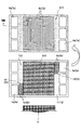
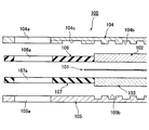
- a plurality of manifold holes 104a, 105a, 106a, 107a are opened in the separators 104, 105 and the gaskets 106, 107 respectively, and as shown in FIGS. 11 and 12, the separators 104, 105 face the GDLs 102, 103.
- a fuel gas reaction groove 104b and an oxidant gas reaction groove 105b are formed on the surface (the gas reaction region 100A by the MEA 101 shown in FIG. 13), and a manifold on the surface of the separators 104 and 105 facing the gaskets 106 and 107.
- a gas introduction groove 104c and a gas introduction groove 105c are formed, which communicate the holes 104a and 105a with the gas reaction region 100A (the fuel gas reaction groove 104b and the oxidant gas reaction groove 105b).
- the manifold holes 104 a and 105 a of the separators 104 and 105 and the manifold holes 106 a and 107 a of the gaskets 106 and 107 are polymerized (connected) with each other to supply the fuel gas, the oxidant gas and the refrigerant.
- a passage and a discharge passage (manifold hole) are formed.
- the fuel gas (hydrogen) flowing through the manifold hole is one catalyst of the MEA 101 through the gas introduction groove 104c, the fuel gas reaction groove 104b and one GDL 102.
- the oxidant gas (air) supplied to the electrode layer (anode) side and flowing through the other manifold holes is the other catalyst electrode of the MEA 101 via the gas introduction groove 105c, the oxidant gas reaction groove 105b and the other GDL 103. It is supplied to the layer (cathode) side, and generates electric power by the reverse reaction of water electrolysis, that is, the reaction of generating water from hydrogen and oxygen.
- the electromotive force by each fuel cell 100 is low, the necessary electromotive force can be obtained by stacking a large number of fuel cells 100 to form an electrical series connection. (See, for example, Patent Documents 1 and 2).
- Fuel cells of this type are required to further reduce the size and cost of the stack, and as described above, the GDLs 102 and 103 with the gaskets 106 and 107 integrated are a stack assembly. The workability at the time etc. is improved, which is effective for cost reduction.
- the gas introduction groove 104c and the gas introduction groove 105c between the manifold hole and the gas reaction region 100A are formed by processing the separators 104 and 105. , Processing cost is high.
- the present invention has been made in view of the above-described points, and its technical object is to realize further cost reduction of a fuel cell stack by improving a gasket for a fuel cell.
- the gasket for a fuel cell according to the invention of claim 1 is integrally formed of a rubber-like elastic material on the outer periphery of GDL interposed between the separator and MEA.
- a gas introduction groove is formed on the surface of the gasket facing the separator, the gas introduction groove extending so as to connect the manifold hole formed in the gasket and the gas reaction region by the MEA. It is characterized by
- a gasket for a fuel cell according to the invention of claim 2 is characterized in that, in the configuration described in claim 1, a reinforcing plate is integrally provided.
- a gasket for a fuel cell according to the invention of claim 3 is characterized in that, in the configuration described in claim 2, the gas introducing groove is formed in the reinforcing plate.
- the gas introduction groove formed in the gasket forms a flow path for circulating the reaction gas (fuel gas and oxidant gas) between the manifold hole and the gas reaction area,
- the gas introduction groove can be formed simultaneously with the formation of the gasket made of the rubber-like elastic material, and there is no need to process the gas introduction groove on the separator side, so the cost can be reduced.
- the reinforcing plate integrally provided in the gasket prevents the reduction of the mechanical strength of the gasket due to the gas introduction groove, and the fuel cell stack can be easily assembled.
- the fuel cell stack can be easily assembled.
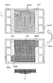
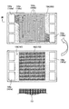
- FIG. 1 is a plan view of a first embodiment of a fuel cell gasket according to the present invention, as viewed from the stacking direction together with an MEA and a separator.
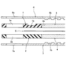
- FIG. 2 is a partial cross-sectional view of the first embodiment of the fuel cell gasket according to the present invention, taken along the line II in FIG. 1 along with the MEA and the separator.
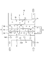
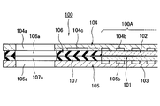
- FIG. 2 is a partial cross-sectional view of a stacked state in which the first embodiment of the fuel cell gasket according to the present invention is cut along line II in FIG. 1 together with MEA and a separator. It is an explanatory view showing roughly a mechanism of power generation in a fuel cell.
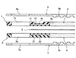
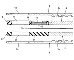
- FIG. 6 is a partial cross-sectional view of a second embodiment of the gasket for a fuel cell according to the present invention, taken along the line VV in FIG. 5 along with the MEA and the separator.
- FIG. 16 is a partial cross-sectional view of a second embodiment of the fuel cell gasket according to the present invention, taken along line VV in FIG. 5 along with the MEA and the separator. It is the top view of the isolation
- FIG. 9 is a partial cross-sectional view of a third embodiment of the fuel cell gasket according to the present invention, taken along line VIII-VIII in FIG. 8 together with MEA and a separator.
- FIG. 9 is a partial cross-sectional view of a stacked state in which a third embodiment of a fuel cell gasket according to the present invention is cut along line VIII-VIII in FIG. 8 together with MEA and a separator. It is the top view of the isolation
- FIG. 12 is a partial cross-sectional view in a separated state, showing one example of a fuel cell gasket according to the prior art, together with an MEA and a separator, at a position XI-XI in FIG.
- FIG. 12 is a partial cross-sectional view of a stacked state in which an example of a fuel cell gasket according to the prior art is cut along line XI-XI in FIG. 11 together with MEA and a separator.
- FIG. 1 is a plan view of the first embodiment of the gasket for a fuel cell according to the present invention as viewed from the stacking direction together with the MEA and the separator
- FIG. 3 is a partial cross-sectional view of the separated state shown in a cut along a line II in FIG.
- Reference numerals 1 and 2 in these figures are gaskets according to the present invention, which are rubbery elastic materials (rubber materials or synthetic resin materials having rubbery elasticity), preferably ethylene propylene rubber (EPDM), silicone rubber (VMQ) And fluorine rubber (FKM), perfluoro rubber (FFKM) and the like, and is molded into a plate or sheet.
- rubbery elastic materials rubber materials or synthetic resin materials having rubbery elasticity
- EPDM ethylene propylene rubber
- VMQ silicone rubber
- FKM fluorine rubber
- FFKM perfluoro rubber
- GDL (Gas Diffusion Layer: gas diffusion layer) 3 and 4 are isomorphous and is made of a porous conductive material such as a porous metal body or carbon fiber having innumerable fine through-pores which allow gas to flow.
- the gaskets 1 and 2 surround the outer periphery of the GDLs 3 and 4 by a part of the rubber-like elastic material penetrating to the edge of the GDLs 3 and 4 and curing. As a result, the GDLs 3 and 4 are integrally formed.
- reference numeral 5 is an MEA (Membrane Electrode Assembly: membrane-electrode complex), which comprises an electrolyte membrane and catalyst electrode layers (not shown) provided on both sides thereof, and reference numerals 6, 7 are made of carbon or conductive metal Separator.
- MEA Membrane Electrode Assembly: membrane-electrode complex
- the fuel cell 10 which is the minimum unit of electric power generation is comprised by clamping MEA5 by the separators 6 and 7 via GDL3 and 4 from the thickness direction both sides.
- the outer peripheral portion of the MEA 5 is closely held by the gaskets 1 and 2 on both sides thereof, and the surfaces of the gaskets 1 and 2 opposite to the MEA 5 are in close contact with the separators 6 and 7.
- a plurality of pairs of manifold holes 1a and 2a are opened in the gaskets 1 and 2, and manifold holes 6a and 7a are opened in the separators 6 and 7 at positions corresponding to the manifold holes 1a and 2a of the gaskets 1 and 2, respectively. It is done. Therefore, in the laminated state shown in FIG. 3, the manifold holes 1a, 2a and 6a, 7a are polymerized (communicated) with each other to form a supply passage and a discharge passage (manifold hole) of the fuel gas, the oxidant gas and the refrigerant. .
- a plurality of fuel gas reaction grooves 6b are formed on the surface of one separator 6 facing GDL3, and a plurality of oxidant gas reaction grooves 7b are formed on the other surface of separator 7 facing GDL4.
- a region where the MEA 5, GDLs 3 and 4, the fuel gas reaction groove 6b and the oxidant gas reaction groove 7b are polymerized with each other is the gas reaction region 10A, ie, a power generation region.
- the gaskets 1 and 2 seal the periphery of the gas reaction area 10A.
- a gas introduction groove 1b is formed on the surface of the gasket 1 facing the separator 6 so as to connect the manifold hole 1a and the fuel gas reaction groove 6b in the gas reaction region 10A with each other.
- a gas introduction groove 2b extending so as to connect the manifold hole 2a and the oxidant gas reaction groove 7b in the gas reaction region 10A with each other is formed on the opposite surface to the separator 7 (see FIGS. 2 and 3) The introduction groove 2b is not shown).
- the gas introduction groove 1b of the gasket 1 is extended so as to reach the end of the GDL 3 as indicated by reference numeral 3a in FIG. 2, and the gas introduction groove 2b of the gasket 2 is similarly the end of GDL 4 It is extended to reach to.
- the fuel gas containing hydrogen H 2 forms a fuel gas flow path (the gas introduction groove 1 b and the fuel gas reaction groove 6 b) and one GDL 3.
- the oxidant gas (air) supplied to one catalyst electrode layer (anode) 52 in the MEA 5 and containing oxygen O 2 is an oxidant gas flow path (the gas introduction groove 2 b and the oxidant gas reaction groove 7 b) and the other
- the GDL 4 is supplied to the other catalyst electrode layer (cathode) 53 in the MEA 5 to generate electric power by an electrochemical reaction that generates water H 2 O from hydrogen H 2 and oxygen O 2 .
- hydrogen H 2 in the fuel gas supplied to the anode 52 in the MEA 5 is decomposed into electrons e ⁇ and hydrogen ions H + by the catalytic action of the anode 52, and the electrons e ⁇ pass through the external load R as a current.
- the hydrogen ions H + generated by the separation of the electrons e ⁇ from the hydrogen H 2 are attracted to the electrons e ⁇ of the cathode 53 and move to the cathode 53 through the electrolyte membrane 51 in the MEA 5.
- oxygen O 2 in the oxidant gas supplied to the cathode 53 in the MEA 5 receives electrons e ⁇ by the catalytic action of the cathode 53 to become oxygen ions O ⁇ .
- the oxygen ions O - is from the anode 52 of water H 2 O is produced by associating with movement to come hydrogen ions H + through the electrolyte membrane 51.
- the flow of the fuel gas, the oxidant gas or the like between the reaction groove 7b is performed via the gas introduction groove 1b or 2b. Since the gas introduction grooves 1b and 2b are extended to reach the end portions of the GDLs 3 and 4, the flow between the fuel gas reaction groove 6b and the oxidant gas reaction groove 7b is smoothly performed. It will be.
- gas introduction groove 1b, 2b is formed in the gaskets 1 and 2, it is not necessary to process a gas introduction groove in the separators 6 and 7 side which consist of metals or carbon. Moreover, since the gas introduction grooves 1b and 2b are simultaneously formed in the molding die when integrally forming the gaskets 1 and 2 of the rubber-like elastic material into the GDLs 3 and 4, cost can be reduced.
- FIG. 5 is a plan view of the second embodiment of the fuel cell gasket according to the present invention, as viewed from the stacking direction together with the MEA and the separator, and FIG. 6 is a VV line position of FIG.
- FIG. 7 is a partial cross-sectional view of another example of the second embodiment taken along line VV in FIG. 5 along with the MEA and the separator.
- the second embodiment differs from the first embodiment in that the gaskets 1 and 2 are integrally formed with gasket bodies 11 and 21 made of a rubber-like elastic material and the gasket bodies 11 and 21, respectively.
- the reinforcing plate 12, 22 is made of a material having rigidity higher than that of the rubber-like elastic material, such as synthetic resin or metal.
- the plane projection shape of the reinforcing plates 12 and 22 is substantially similar to the plane projection shape of the gasket bodies 11 and 21.
- the configuration of the other parts is basically the same as that of the first embodiment.
- the reinforcing plates 12 and 22 are embedded in the gasket main bodies 11 and 21 when the material of the reinforcing plates 12 and 22 is insufficient in chemical stability with respect to fuel gas and oxidant gas. By integrally molding in the state, the reinforcing plates 12 and 22 are prevented from contacting the fuel gas and the oxidant gas.
- the reinforcing plates 12 and 22 are in a semi-embedded state, ie, the gasket main body 11 , 21 and integrally molded in the embedded state.
- the outer peripheral portion of the MEA 5 is sealed by the intimate contact of the gasket bodies 11 and 21.
- the mechanical strength of the gaskets 1 and 2 is compensated by the reinforcing plates 12 and 22 integrally provided on the entire area of the gasket bodies 11 and 21, that is, the formation of the gas introduction grooves 1b and 2b. Since the strength reduction of the gaskets 1 and 2 due to is prevented, the assembly of the cell (stack) can be facilitated.
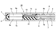
- FIG. 8 is a plan view of the third embodiment of the gasket for a fuel cell according to the present invention, as viewed from the stacking direction together with the MEA and the separator, and FIG. 9 is a line VIII-VIII in FIG.
- FIG. 10 is a partial cross-sectional view of a stacked state shown in a section along line VIII-VIII in FIG.
- the gaskets 1 and 2 each include a gasket body 11 or 21 made of a rubber-like elastic material, and between the manifold holes 1a and 2a and the GDLs 3 and 4 in the gasket body 11 or 21, that is, gas introduction.
- the reinforcing plates 13 and 23 are integrally formed on the forming regions of the grooves 1b and 2b and the reinforcing plates 13 and 23 are made of a material having rigidity higher than that of the rubber-like elastic material, such as fuel gas or the like. It consists of a synthetic resin or metal etc.
- the other configuration is basically the same as that of the first embodiment.
- the mechanical strength of the formation portion of the gas introduction grooves 1b and 2b in the gaskets 1 and 2 is compensated, so that the assembly of the cell (stack) can be facilitated.
- the contraction of the flow paths of the gas introduction grooves 1b and 2b due to the compression of the gasket bodies 11 and 21 in the stacked state shown in FIG. 10 is prevented.
- the gaskets 1 and 2 are obtained by forming the gas introduction grooves 1b and 2b in advance in the reinforcing plates 13 and 23, and integrally forming the gasket bodies 11 and 21 on the reinforcing plates 13 and 23, respectively.
- the design change of the gas introduction grooves 1b and 2b can be coped with by the design change of only the reinforcing plates 13 and 23, and therefore, it can also contribute to the cost reduction at the time of such design change.
Abstract
Description
11,21 ガスケット本体
12,13,22,23 補強板
1a,2a,6a,7a マニホールド孔
1b,2b ガス導入溝
3,4 GDL
5 MEA
6,7 セパレータ
6b 燃料ガス反応用溝
7b 酸化剤ガス反応用溝
10A ガス反応領域 1, 2
5 MEA
6, 7
Claims (3)
- セパレータとMEAの間に介在されるGDLの外周にゴム状弾性材料で一体に成形され、前記セパレータと密接されるガスケットにおいて、このガスケットの前記セパレータとの対向面に、このガスケットに開設されたマニホールド孔と前記MEAによるガス反応領域を互いに連通するように延びるガス導入溝が形成されたことを特徴とする燃料電池用ガスケット。 A gasket formed integrally with a rubber-like elastic material on the outer periphery of the GDL interposed between the separator and the MEA, and intimately attached to the separator, a manifold provided in the gasket on the opposite surface of the gasket to the separator A gasket for a fuel cell, comprising: a gas introduction groove extending so as to connect a hole and a gas reaction region by the MEA to each other.
- 補強板が一体に設けられたことを特徴とする請求項1に記載の燃料電池用ガスケット。 The gasket for a fuel cell according to claim 1, wherein a reinforcing plate is integrally provided.
- ガス導入溝が補強板に形成されたことを特徴とする請求項2に記載の燃料電池用ガスケット。 The gasket for a fuel cell according to claim 2, wherein the gas introduction groove is formed in the reinforcing plate.
Priority Applications (3)
| Application Number | Priority Date | Filing Date | Title |
|---|---|---|---|
| KR1020137034361A KR102017312B1 (en) | 2011-07-19 | 2012-07-19 | Gasket for fuel cell |
| EP12814585.1A EP2736108B1 (en) | 2011-07-19 | 2012-07-19 | Gasket for fuel cell |
| CN201280035047.0A CN103688398B (en) | 2011-07-19 | 2012-07-19 | gasket for fuel cell |
Applications Claiming Priority (2)
| Application Number | Priority Date | Filing Date | Title |
|---|---|---|---|
| JP2011157730A JP5835554B2 (en) | 2011-07-19 | 2011-07-19 | Gasket for fuel cell |
| JP2011-157730 | 2011-07-19 |
Publications (1)
| Publication Number | Publication Date |
|---|---|
| WO2013012026A1 true WO2013012026A1 (en) | 2013-01-24 |
Family
ID=47558201
Family Applications (1)
| Application Number | Title | Priority Date | Filing Date |
|---|---|---|---|
| PCT/JP2012/068285 WO2013012026A1 (en) | 2011-07-19 | 2012-07-19 | Gasket for fuel cell |
Country Status (5)
| Country | Link |
|---|---|
| EP (1) | EP2736108B1 (en) |
| JP (1) | JP5835554B2 (en) |
| KR (1) | KR102017312B1 (en) |
| CN (1) | CN103688398B (en) |
| WO (1) | WO2013012026A1 (en) |
Families Citing this family (4)
| Publication number | Priority date | Publication date | Assignee | Title |
|---|---|---|---|---|
| KR20170076517A (en) | 2015-12-24 | 2017-07-04 | 주식회사 연시스템즈 | Single Lens Camera for three dimensional image |
| KR101714295B1 (en) * | 2016-01-06 | 2017-03-09 | 현대자동차주식회사 | Fuel cell |
| KR102602415B1 (en) | 2018-09-04 | 2023-11-14 | 현대자동차주식회사 | Membrane Electrode Assembly |
| DE102021114842A1 (en) * | 2021-06-09 | 2022-12-15 | MTU Aero Engines AG | fuel cell assembly |
Citations (4)
| Publication number | Priority date | Publication date | Assignee | Title |
|---|---|---|---|---|
| JP2000012053A (en) * | 1998-06-25 | 2000-01-14 | Aisin Seiki Co Ltd | Solid high-polymer electrolyte-type fuel cell |
| WO2001059864A1 (en) * | 2000-02-08 | 2001-08-16 | Matsushita Electric Industrial Co., Ltd. | Polymer electrolyte fuel cell |
| JP2004335453A (en) | 2003-04-14 | 2004-11-25 | Matsushita Electric Ind Co Ltd | Cell for fuel cell, fuel cell, fuel cell power generating system and manufacturing methods of fuel cell |
| JP2007026847A (en) | 2005-07-15 | 2007-02-01 | Nok Corp | Seal structure body for fuel cell and its manufacturing method |
Family Cites Families (2)
| Publication number | Priority date | Publication date | Assignee | Title |
|---|---|---|---|---|
| JP5164348B2 (en) * | 2006-08-03 | 2013-03-21 | 日本ゴア株式会社 | Membrane electrode assembly, method for producing the same, and polymer electrolyte fuel cell using the same |
| JP5200346B2 (en) * | 2006-08-25 | 2013-06-05 | トヨタ自動車株式会社 | Fuel cell and fuel cell having the same |
-
2011
- 2011-07-19 JP JP2011157730A patent/JP5835554B2/en active Active
-
2012
- 2012-07-19 KR KR1020137034361A patent/KR102017312B1/en active IP Right Grant
- 2012-07-19 WO PCT/JP2012/068285 patent/WO2013012026A1/en active Application Filing
- 2012-07-19 CN CN201280035047.0A patent/CN103688398B/en active Active
- 2012-07-19 EP EP12814585.1A patent/EP2736108B1/en not_active Not-in-force
Patent Citations (4)
| Publication number | Priority date | Publication date | Assignee | Title |
|---|---|---|---|---|
| JP2000012053A (en) * | 1998-06-25 | 2000-01-14 | Aisin Seiki Co Ltd | Solid high-polymer electrolyte-type fuel cell |
| WO2001059864A1 (en) * | 2000-02-08 | 2001-08-16 | Matsushita Electric Industrial Co., Ltd. | Polymer electrolyte fuel cell |
| JP2004335453A (en) | 2003-04-14 | 2004-11-25 | Matsushita Electric Ind Co Ltd | Cell for fuel cell, fuel cell, fuel cell power generating system and manufacturing methods of fuel cell |
| JP2007026847A (en) | 2005-07-15 | 2007-02-01 | Nok Corp | Seal structure body for fuel cell and its manufacturing method |
Non-Patent Citations (1)
| Title |
|---|
| See also references of EP2736108A4 * |
Also Published As
| Publication number | Publication date |
|---|---|
| CN103688398A (en) | 2014-03-26 |
| KR102017312B1 (en) | 2019-09-02 |
| KR20140048148A (en) | 2014-04-23 |
| EP2736108A4 (en) | 2015-01-07 |
| JP5835554B2 (en) | 2015-12-24 |
| EP2736108B1 (en) | 2017-04-19 |
| CN103688398B (en) | 2017-02-15 |
| JP2013025928A (en) | 2013-02-04 |
| EP2736108A1 (en) | 2014-05-28 |
Similar Documents
| Publication | Publication Date | Title |
|---|---|---|
| JP5412804B2 (en) | Fuel cell stack | |
| US7531265B2 (en) | Fuel cell | |
| US7759014B2 (en) | Fuel cell having a seal member | |
| US9490497B2 (en) | Solid polymer electrolyte type fuel cell, and electrolyte membrane-electrode-frame assembly | |
| US20110014541A1 (en) | Fuel Cell Gas Diffusion Layer Integrated Gasket | |
| JP3799038B2 (en) | Separator for polymer electrolyte fuel cell | |
| WO2013012026A1 (en) | Gasket for fuel cell | |
| JP2004207074A (en) | Fuel cell | |
| KR20100030709A (en) | Bipolarplate for fuel cell stack | |
| US7824817B2 (en) | Fuel cell | |
| JP2015032421A (en) | Fuel cell stack | |
| JP2006269159A (en) | Fuel cell stack | |
| JP5259888B1 (en) | Polymer electrolyte fuel cell | |
| US9350034B2 (en) | Fuel cell gas diffusion layer integrated gasket | |
| JP2009252420A (en) | Fuel cell and resin frame for fuel cell | |
| JP2008186736A (en) | Fuel cell stack | |
| JP2006012462A (en) | Sealing structure for fuel cell | |
| JP2007042471A (en) | Fuel cell stack | |
| JP2004311155A (en) | Fuel cell stack | |
| JP2005174642A (en) | Separator | |
| JP5050434B2 (en) | Fuel cell | |
| JP2014063583A (en) | Fuel cell stack | |
| JP2006120547A (en) | Fuel cell | |
| JP2016131086A (en) | Fuel battery | |
| JP2015097154A (en) | Fuel cell gasket |
Legal Events
| Date | Code | Title | Description |
|---|---|---|---|
| 121 | Ep: the epo has been informed by wipo that ep was designated in this application |
Ref document number: 12814585 Country of ref document: EP Kind code of ref document: A1 |
|
| REEP | Request for entry into the european phase |
Ref document number: 2012814585 Country of ref document: EP |
|
| WWE | Wipo information: entry into national phase |
Ref document number: 2012814585 Country of ref document: EP |
|
| ENP | Entry into the national phase |
Ref document number: 20137034361 Country of ref document: KR Kind code of ref document: A |
|
| NENP | Non-entry into the national phase |
Ref country code: DE |