WO2013008538A1 - Image processing apparatus and image processing method - Google Patents
Image processing apparatus and image processing method Download PDFInfo
- Publication number
- WO2013008538A1 WO2013008538A1 PCT/JP2012/063321 JP2012063321W WO2013008538A1 WO 2013008538 A1 WO2013008538 A1 WO 2013008538A1 JP 2012063321 W JP2012063321 W JP 2012063321W WO 2013008538 A1 WO2013008538 A1 WO 2013008538A1
- Authority
- WO
- WIPO (PCT)
- Prior art keywords
- motion vector
- unit
- prediction unit
- layer
- information
- Prior art date
Links
Images


Classifications
-
- H—ELECTRICITY
- H04—ELECTRIC COMMUNICATION TECHNIQUE
- H04N—PICTORIAL COMMUNICATION, e.g. TELEVISION
- H04N19/00—Methods or arrangements for coding, decoding, compressing or decompressing digital video signals
- H04N19/50—Methods or arrangements for coding, decoding, compressing or decompressing digital video signals using predictive coding
- H04N19/503—Methods or arrangements for coding, decoding, compressing or decompressing digital video signals using predictive coding involving temporal prediction
- H04N19/51—Motion estimation or motion compensation
-
- H—ELECTRICITY
- H04—ELECTRIC COMMUNICATION TECHNIQUE
- H04N—PICTORIAL COMMUNICATION, e.g. TELEVISION
- H04N19/00—Methods or arrangements for coding, decoding, compressing or decompressing digital video signals
- H04N19/10—Methods or arrangements for coding, decoding, compressing or decompressing digital video signals using adaptive coding
- H04N19/102—Methods or arrangements for coding, decoding, compressing or decompressing digital video signals using adaptive coding characterised by the element, parameter or selection affected or controlled by the adaptive coding
- H04N19/103—Selection of coding mode or of prediction mode
-
- H—ELECTRICITY
- H04—ELECTRIC COMMUNICATION TECHNIQUE
- H04N—PICTORIAL COMMUNICATION, e.g. TELEVISION
- H04N19/00—Methods or arrangements for coding, decoding, compressing or decompressing digital video signals
- H04N19/10—Methods or arrangements for coding, decoding, compressing or decompressing digital video signals using adaptive coding
- H04N19/134—Methods or arrangements for coding, decoding, compressing or decompressing digital video signals using adaptive coding characterised by the element, parameter or criterion affecting or controlling the adaptive coding
- H04N19/136—Incoming video signal characteristics or properties
- H04N19/137—Motion inside a coding unit, e.g. average field, frame or block difference
- H04N19/139—Analysis of motion vectors, e.g. their magnitude, direction, variance or reliability
-
- H—ELECTRICITY
- H04—ELECTRIC COMMUNICATION TECHNIQUE
- H04N—PICTORIAL COMMUNICATION, e.g. TELEVISION
- H04N19/00—Methods or arrangements for coding, decoding, compressing or decompressing digital video signals
- H04N19/10—Methods or arrangements for coding, decoding, compressing or decompressing digital video signals using adaptive coding
- H04N19/169—Methods or arrangements for coding, decoding, compressing or decompressing digital video signals using adaptive coding characterised by the coding unit, i.e. the structural portion or semantic portion of the video signal being the object or the subject of the adaptive coding
- H04N19/17—Methods or arrangements for coding, decoding, compressing or decompressing digital video signals using adaptive coding characterised by the coding unit, i.e. the structural portion or semantic portion of the video signal being the object or the subject of the adaptive coding the unit being an image region, e.g. an object
- H04N19/176—Methods or arrangements for coding, decoding, compressing or decompressing digital video signals using adaptive coding characterised by the coding unit, i.e. the structural portion or semantic portion of the video signal being the object or the subject of the adaptive coding the unit being an image region, e.g. an object the region being a block, e.g. a macroblock
-
- H—ELECTRICITY
- H04—ELECTRIC COMMUNICATION TECHNIQUE
- H04N—PICTORIAL COMMUNICATION, e.g. TELEVISION
- H04N19/00—Methods or arrangements for coding, decoding, compressing or decompressing digital video signals
- H04N19/10—Methods or arrangements for coding, decoding, compressing or decompressing digital video signals using adaptive coding
- H04N19/169—Methods or arrangements for coding, decoding, compressing or decompressing digital video signals using adaptive coding characterised by the coding unit, i.e. the structural portion or semantic portion of the video signal being the object or the subject of the adaptive coding
- H04N19/187—Methods or arrangements for coding, decoding, compressing or decompressing digital video signals using adaptive coding characterised by the coding unit, i.e. the structural portion or semantic portion of the video signal being the object or the subject of the adaptive coding the unit being a scalable video layer
-
- H—ELECTRICITY
- H04—ELECTRIC COMMUNICATION TECHNIQUE
- H04N—PICTORIAL COMMUNICATION, e.g. TELEVISION
- H04N19/00—Methods or arrangements for coding, decoding, compressing or decompressing digital video signals
- H04N19/30—Methods or arrangements for coding, decoding, compressing or decompressing digital video signals using hierarchical techniques, e.g. scalability
- H04N19/36—Scalability techniques involving formatting the layers as a function of picture distortion after decoding, e.g. signal-to-noise [SNR] scalability
-
- H—ELECTRICITY
- H04—ELECTRIC COMMUNICATION TECHNIQUE
- H04N—PICTORIAL COMMUNICATION, e.g. TELEVISION
- H04N19/00—Methods or arrangements for coding, decoding, compressing or decompressing digital video signals
- H04N19/46—Embedding additional information in the video signal during the compression process
-
- H—ELECTRICITY
- H04—ELECTRIC COMMUNICATION TECHNIQUE
- H04N—PICTORIAL COMMUNICATION, e.g. TELEVISION
- H04N19/00—Methods or arrangements for coding, decoding, compressing or decompressing digital video signals
- H04N19/50—Methods or arrangements for coding, decoding, compressing or decompressing digital video signals using predictive coding
- H04N19/503—Methods or arrangements for coding, decoding, compressing or decompressing digital video signals using predictive coding involving temporal prediction
- H04N19/51—Motion estimation or motion compensation
- H04N19/513—Processing of motion vectors
- H04N19/517—Processing of motion vectors by encoding
- H04N19/52—Processing of motion vectors by encoding by predictive encoding
Definitions
- the present disclosure relates to an image processing apparatus and an image processing method.
- the purpose is to efficiently transmit or store digital images, and to compress the amount of information of images using image-specific redundancy.
- Compression techniques such as the 26x (ITU-T Q6 / 16 VCEG) standard and the Moving Picture Experts Group (MPEG) -y standard are widespread.
- MPEG Moving Picture Experts Group
- H.264 is used. Based on the 26x standard and incorporating new functions, higher compression rates can be achieved.
- An international standard named H.264 and MPEG-4 Part 10 Advanced Video Coding; AVC
- inter-frame prediction the content of the image to be encoded is predicted using the reference image, and only the difference between the predicted image and the actual image is encoded. Thereby, compression of the code amount is realized.
- the difference between the predicted image and the actual image is large, and a simple compression between frames can not be obtained. Therefore, the motion of the object is recognized as a motion vector, and the pixel value of the region where the motion appears is compensated according to the motion vector, thereby reducing the prediction error in inter-frame prediction.
- Such a method is called motion compensation.
- each coding unit (CU: Coding Unit) in an image is one or more prediction units. (PU: Prediction Unit), and motion vectors can be set for each prediction unit.
- the size and shape of the prediction unit of HEVC is H.264. It is more diverse than H.264 / AVC blocks and can more accurately reflect the motion of an object in motion compensation (see Non-Patent Document 1 below).
- Non-Patent Document 2 below predicts a motion vector using spatial correlation or temporal correlation of motion in order to reduce the code amount of the motion vector, and only the difference between the predicted motion vector and the actual motion vector.
- Non-Patent Document 3 below proposes to reduce the code amount of motion information by merging blocks having common motion information among adjacent blocks in an image.
- Scalable coding refers to a technology for hierarchically coding a layer transmitting a coarse image signal and a layer transmitting a fine image signal.
- the following three types of typical attributes are layered in scalable coding.
- -Spatial scalability spatial resolution or image size is layered.
- -Temporal scalability Frame rates are layered.
- -Signal to Noise Ratio (SNR) scalability SN ratios are layered.
- SNR Signal to Noise Ratio
- JCTVC-B205 “Test Model under Consideration”, Joint Collaborative Team on Video Coding meeting: Geneva, CH, 21-28 July, 2010
- VCEG-AI22 “Motion Vector Coding with Optimal PMV Selection”
- Jungyoup Yang et al, July, 2008
- JCTVC-A116 “Video Coding Technology Proposal by Fraunhofer HHI”
- M. Winken et al, April, 2010
- Non-Patent Document 2 described above and the method proposed by Non-Patent Document 3 do not assume scalable coding. If these existing techniques are applied to each layer of an image to be scalable coded, it is possible to expect a reduction in the amount of code to some extent. However, depending on the type of scalable coding, the correlation of motion between layers is remarkable. Therefore, it is useful to exploit such motion correlation between layers to improve coding efficiency.
- the technology according to the present disclosure aims to enhance coding efficiency by utilizing the correlation of motion between layers of an image to be scalable coded.
- the second corresponding to the first prediction unit in the first layer of the image to be scalable decoded including the first layer and a second layer higher than the first layer.
- Setting information for setting a motion vector in a second prediction unit in the layer wherein the information acquisition unit acquires the setting information related to the motion vector set in the first prediction unit;
- an image processing apparatus comprising: a motion vector setting unit configured to set a motion vector in the second prediction unit using the setting information acquired by the information acquisition unit.
- the image processing apparatus can be typically realized as an image decoding apparatus that decodes an image.
- the first prediction unit in the first layer of the image to be scalable-decoded including the first layer and a second layer higher than the first layer corresponds to the first prediction unit.
- the first prediction unit in the first layer of the image to be scalable-decoded including the first layer and a second layer higher than the first layer corresponds to the first prediction unit.
- An image processing apparatus comprising: an encoding unit that encodes the setting information generated by the information generation unit.
- the image processing apparatus can be typically realized as an image coding apparatus that codes an image.
- the first prediction unit in the first layer of the image to be scalable-decoded including the first layer and a second layer higher than the first layer corresponds to the first prediction unit.
- coding efficiency is further enhanced by exploiting the correlation of motion between layers of the scalable coded image.
- FIG. 7 is a first explanatory diagram for describing an example of predictor candidates for prediction of a motion vector.
- FIG. 10 is a second explanatory diagram for describing an example of a predictor candidate for prediction of a motion vector. It is a flowchart which shows an example of the flow of the motion search process by the motion search part which concerns on a 1st Example.
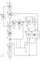
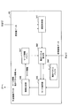
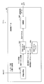
- FIG. 1 is a block diagram showing an example of the configuration of an image coding apparatus 10 according to an embodiment.
- the image coding apparatus 10 includes an A / D (Analogue to Digital) conversion unit 11, a rearrangement buffer 12, a subtraction unit 13, an orthogonal conversion unit 14, a quantization unit 15, a lossless encoding unit 16, Storage buffer 17, rate control unit 18, dequantization unit 21, inverse orthogonal transformation unit 22, addition unit 23, deblock filter 24, frame memory 25, selectors 26 and 27, intra prediction unit 30, and motion search unit 40.
- a / D Analogue to Digital
- the A / D converter 11 converts an image signal input in an analog format into image data in a digital format, and outputs a series of digital image data to the sorting buffer 12.
- the rearrangement buffer 12 rearranges the images included in the series of image data input from the A / D converter 11.
- the rearrangement buffer 12 rearranges the images according to the GOP (Group of Pictures) structure related to the encoding process, and then outputs the rearranged image data to the subtraction unit 13, the intra prediction unit 30, and the motion search unit 40. Do.
- GOP Group of Pictures
- the subtraction unit 13 is supplied with the image data input from the reordering buffer 12 and the prediction image data input from the intra prediction unit 30 or the motion search unit 40 described later.
- the subtraction unit 13 calculates prediction error data which is a difference between the image data input from the reordering buffer 12 and the prediction image data, and outputs the calculated prediction error data to the orthogonal transformation unit 14.
- the orthogonal transformation unit 14 performs orthogonal transformation on the prediction error data input from the subtraction unit 13.
- the orthogonal transformation performed by the orthogonal transformation unit 14 may be, for example, Discrete Cosine Transform (DCT) or Karhunen-Loeve Transform.
- the orthogonal transform unit 14 outputs transform coefficient data acquired by the orthogonal transform process to the quantization unit 15.
- the quantization unit 15 is supplied with transform coefficient data input from the orthogonal transform unit 14 and a rate control signal from the rate control unit 18 described later.
- the quantizing unit 15 quantizes the transform coefficient data, and outputs the quantized transform coefficient data (hereinafter, referred to as quantized data) to the lossless encoding unit 16 and the inverse quantization unit 21. Further, the quantization unit 15 changes the bit rate of the quantization data input to the lossless encoding unit 16 by switching the quantization parameter (quantization scale) based on the rate control signal from the rate control unit 18 Let
- the lossless encoding unit 16 generates an encoded stream by performing lossless encoding processing on the quantized data input from the quantization unit 15.
- the lossless coding by the lossless coding unit 16 may be, for example, variable length coding or arithmetic coding.
- the lossless encoding unit 16 multiplexes the information on the intra prediction or the information on the inter prediction input from the selector 27 in the header area of the encoded stream. Then, the lossless encoding unit 16 outputs the generated encoded stream to the accumulation buffer 17.
- the accumulation buffer 17 temporarily accumulates the encoded stream input from the lossless encoding unit 16. Then, the accumulation buffer 17 outputs the accumulated encoded stream to a transmission unit (not shown) (for example, a communication interface or a connection interface with a peripheral device) at a rate according to the band of the transmission path.
- a transmission unit for example, a communication interface or a connection interface with a peripheral device
- the rate control unit 18 monitors the free space of the accumulation buffer 17. Then, the rate control unit 18 generates a rate control signal according to the free space of the accumulation buffer 17, and outputs the generated rate control signal to the quantization unit 15. For example, when the free space of the accumulation buffer 17 is small, the rate control unit 18 generates a rate control signal for reducing the bit rate of the quantized data. Also, for example, when the free space of the accumulation buffer 17 is sufficiently large, the rate control unit 18 generates a rate control signal for increasing the bit rate of the quantized data.
- the inverse quantization unit 21 performs inverse quantization processing on the quantized data input from the quantization unit 15. Then, the inverse quantization unit 21 outputs the transform coefficient data acquired by the inverse quantization process to the inverse orthogonal transformation unit 22.
- the inverse orthogonal transform unit 22 restores prediction error data by performing inverse orthogonal transform processing on the transform coefficient data input from the inverse quantization unit 21. Then, the inverse orthogonal transform unit 22 outputs the restored prediction error data to the addition unit 23.
- the addition unit 23 generates decoded image data by adding the restored prediction error data input from the inverse orthogonal transform unit 22 and the predicted image data input from the intra prediction unit 30 or the motion search unit 40. . Then, the adding unit 23 outputs the generated decoded image data to the deblocking filter 24 and the frame memory 25.
- the deblocking filter 24 performs a filtering process to reduce block distortion that occurs during image coding.
- the deblocking filter 24 removes block distortion by filtering the decoded image data input from the adding unit 23, and outputs the decoded image data after filtering to the frame memory 25.
- the frame memory 25 stores the decoded image data input from the adding unit 23 and the decoded image data after filtering input from the deblocking filter 24 using a storage medium.
- the selector 26 reads the decoded image data after filtering used for inter prediction from the frame memory 25 and supplies the read decoded image data to the motion search unit 40 as reference image data. Further, the selector 26 reads the decoded image data before filtering used for intra prediction from the frame memory 25 and supplies the read decoded image data to the intra prediction unit 30 as reference image data.
- the selector 27 outputs predicted image data as a result of the inter prediction output from the motion search unit 40 to the subtraction unit 13 in the inter prediction mode, and outputs information on the inter prediction to the lossless encoding unit 16.
- the selector 27 outputs predicted image data as a result of intra prediction output from the intra prediction unit 30 to the subtraction unit 13 and also outputs information on intra prediction to the lossless encoding unit 16 .
- the selector 27 switches the inter prediction mode and the intra prediction mode according to the size of the cost function value output from the intra prediction unit 30 and the motion search unit 40.
- the intra prediction unit 30 is set in the image based on the image data to be encoded (original image data) input from the reordering buffer 12 and the decoded image data as reference image data supplied from the frame memory 25. Intra prediction processing for each block being Then, the intra prediction unit 30 outputs information on intra prediction including prediction mode information indicating an optimum prediction mode, a cost function value, and predicted image data to the selector 27.
- the motion search unit 40 performs a motion search process for inter prediction (inter-frame prediction) based on the original image data input from the reordering buffer 12 and the decoded image data supplied via the selector 26.
- the motion search process by the motion search unit 40 according to the present embodiment can be realized by extending the method described in the non-patent document 2 or the method described in the non-patent document 3.
- the motion search unit 40 can generate predictor information indicating an optimum predictor for each prediction unit.
- the motion search unit 40 can generate merge information indicating an optimal merge mode for each prediction unit.
- the motion search unit 40 outputs, to the selector 27, predictor information or merge information, information on inter prediction including motion vector information and reference image information, a cost function value, and predicted image data.
- predictor information or merge information information on inter prediction including motion vector information and reference image information, a cost function value, and predicted image data.
- the image coding apparatus 10 repeats the series of coding processes described here for each of a plurality of layers of an image to be scalable coded.
- the first layer to be encoded is a layer called the base layer that represents the coarsest image.
- the base layer coded stream can be decoded independently without decoding the coded streams of other layers.
- Layers other than the base layer are layers which represent finer images, called enhancement layers.
- the enhancement layer coded stream is coded using information contained in the base layer coded stream to increase coding efficiency. Therefore, in order to reproduce the image of the enhancement layer, the coded streams of both the base layer and the enhancement layer will be decoded.
- the number of layers handled in scalable coding may be three or more.
- the lowest layer is the base layer, and the remaining layers are the enhancement layers.
- the higher enhancement layer coded stream may be coded and decoded using the information contained in the lower enhancement layer or base layer coded stream.
- the dependent layer is referred to as a lower layer, and the dependent layer is referred to as an upper layer.
- correlation of motion between layers is used to efficiently code information on inter prediction. That is, in the inter prediction block, the setting of the motion vector to the upper layer based on the setting information related to the motion vector set to the lower layer is performed.
- the motion search unit 40 shown in FIG. 1 has a buffer for temporarily storing information obtained in inter prediction in the lower layer, and uses information stored in the buffer. Set the motion vector in the upper layer.
- the correlation of motion between layers can be particularly noticeable in scalable coding based on spatial scalability or SNR scalability.
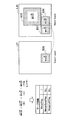
- FIG. 2 is an explanatory diagram for describing an example of spatial scalability.
- Layer L1 is a base layer
- layers L2 and L3 are enhancement layers.
- the ratio of the spatial resolution of layer L2 to layer L1 is 2: 1.
- the ratio of the spatial resolution of layer L3 to layer L1 is 4: 1.
- the motion appearing in prediction unit B1 in layer L1 may similarly appear in the corresponding prediction unit B2 in layer L2 and the corresponding prediction unit B3 in layer L3. Is high. This is the correlation of movement between layers in spatial scalability.
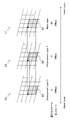
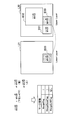
- FIG. 3 is an explanatory diagram for describing an example of the SNR scalability.
- Layer L1 is a base layer
- layers L2 and L3 are enhancement layers.
- the spatial resolutions of layers L1, L2 and L3 are equal to one another.
- the minimum quantization scale of the layer L1 is 25, and the bit rate of the coded stream is suppressed to about 2 Mbps by the quantization of the orthogonal transformation coefficient.
- the minimum quantization scale of the layer L2 is 12, and the bit rate of the encoded stream is about 5 Mbps.
- the minimum quantization scale of the layer L3 is 0, and the bit rate of the encoded stream is about 10 Mbps.
- the motion appearing in the prediction unit B1 in the layer L1 can appear the same in the corresponding prediction unit B2 in the layer L2 and the corresponding prediction unit B3 in the layer L3.
- Sex is high. This is the correlation of motion between layers in SNR scalability.
- the image coding apparatus 10 uses the correlation of motion between layers as described above actively to code information related to inter prediction efficiently.
- the prediction unit of the lower layer corresponding to the prediction unit of the upper layer is, for example, a prediction unit of the lower layer having a pixel corresponding to a pixel at a predetermined position (for example, upper left) of the prediction unit of the upper layer.
- the prediction unit of the lower layer corresponding to the prediction unit of the upper layer is, for example, the largest overlap among prediction units in the lower layer overlapping with the prediction unit of the upper layer (sharing the pixel at the same position) It may be a prediction unit (with the largest number of shared pixels). With such a definition, it is possible to determine a prediction unit that is most likely to exhibit motion correlation as a "corresponding prediction unit”.
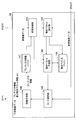
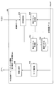
- FIG. 4 is a block diagram showing an example of a detailed configuration of the motion search unit 40 according to the first embodiment.
- the motion search unit 40 includes a search control unit 141, a motion vector calculation unit 142, a motion vector prediction unit 143, a motion vector buffer 144, a mode selection unit 145, an information generation unit 146, and a predictor information buffer 147. .
- the search control unit 141 arranges one or more prediction units in a coding unit, and causes the motion vector calculation unit 142 to calculate a motion vector for each prediction unit.
- the motion vector calculated by the motion vector calculation unit 142 is output to the motion vector prediction unit 143 and stored in the motion vector buffer 144.
- the motion vector prediction unit 143 generates a prediction motion vector using motion vectors (referred to as reference motion vectors) of other blocks stored in the motion vector buffer 144 according to each of the plurality of predictor candidates. Then, the motion vector prediction unit 143 calculates a differential motion vector that is the difference between the motion vector calculated by the motion vector calculation unit 142 and the predicted motion vector.
- the mode selection unit 145 generates predicted image data using the motion vector calculated by the motion vector calculation unit 142, and evaluates a cost function value calculated based on comparison between the generated predicted image data and the original image data. Do. Then, the mode selection unit 145 selects the arrangement of the optimum prediction unit that minimizes the cost function value and the optimum predictor for each prediction unit.
- the information generation unit 146 generates information on inter prediction including predictor information indicating an optimal predictor selected for each prediction unit and differential motion vector information indicating a corresponding differential motion vector.
- the predictor information may include an index specifying a reference motion vector.
- the predictor information may include a parameter specifying a prediction formula.
- the information generation unit 146 outputs the generated information on the inter prediction, the cost function value, and the predicted image data to the selector 27. Further, predictor information generated by the information generation unit 146 is temporarily stored in the predictor information buffer 147 for processing in the upper layer.
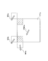
- FIG. 5 and 6 are explanatory diagrams for describing examples of predictor candidates for motion vector prediction that can be used in such inter prediction.
- one prediction unit PTe to be predicted and a prediction motion vector PMVe of the prediction unit PTe are shown.
- the prediction motion vector PMVe of the prediction unit PTe can be predicted, for example, using the motion vectors MVa, MVb and MVc of the prediction unit adjacent to the prediction unit PTe as a reference motion vector.
- the reference motion vector MVa is a motion vector set to a prediction unit adjacent to the left of the prediction unit PTe.
- the reference motion vector MVb is a motion vector set to a prediction unit adjacent above the prediction unit PTe.
- the reference motion vector MVc is a motion vector set to a prediction unit adjacent to the upper right of the prediction unit PTe.
- the predicted motion vector PMVe can be generated according to the following prediction equation using these reference motion vectors MVa, MVb and MVc.
- Equation (1) is a prediction equation based on spatial correlation of motion.
- Med in equation (1) represents a median operation. That is, according to equation (1), the predicted motion vector PMVe is a vector having the median of the horizontal components and the median of the vertical components of the reference motion vectors MVa, MVb and MVc as components.
- the predicted motion vector PMVe generated according to Equation (1) is an example of a predictor candidate.
- a predicted motion vector calculated by a prediction equation based on such spatial correlation of motion is called a spatial predictor.
- Formula (1) is only an example of a prediction formula. For example, if one of the motion vectors MVa, MVb, or MVc does not exist because the prediction unit to be predicted is located at the end of the image, the nonexistent motion vector may be omitted from the argument of the median operation. Good. Also, simpler spatial predictors may also be used as predictor candidates, as in the following equations (2) to (4).
- a temporal predictor which is a predicted motion vector calculated by a prediction equation based on temporal correlation of motion, may also be used as a predictor candidate.
- an image IM01 including a prediction unit PTe to be predicted and a reference image IM02 are shown.
- the block Bcol in the reference image IM02 is a co-located block of the prediction unit PTe.
- the prediction equation using temporal correlation of motion uses, for example, a motion vector set in the co-located block Bcol or a block adjacent to the co-located block B col as a reference motion vector.
- the motion vector set to the co-located block Bcol is taken as MVcol.
- MVt0 to MVt7 be the motion vectors set in the upper, left, lower, right, upper left, lower left, lower right and upper right blocks of the co-located block Bcol, respectively.
- the predicted motion vector PMVe can be generated from the reference motion vectors MVcol and MVt0 to MVt7, for example, using the following prediction equation (5) or (6).
- the motion vector predictor 143 After generating the motion vector predictor PMVe for each of the plurality of predictor candidates, the motion vector predictor 143 generates a difference between the motion vector MVe calculated by the motion vector calculator 142 and the motion vector predictor PMVe as in the following equation. To calculate a differential motion vector MVDe representing.
- the mode selector 145 selects the optimum predictor (for example, the predictor with the highest prediction accuracy) for each prediction unit, and the information generator 146 indicates the predictor information indicating the optimum predictor and the corresponding differential motion vector.
- Differential motion vector information is generated.
- motion vector information indicating a motion vector calculated by the motion vector calculation unit 142 may be generated instead of differential motion vector information.
- the information generated in this manner may be encoded by the lossless encoding unit 16 as information on inter prediction.
- the predictor information is temporarily stored in the predictor information buffer 147 for processing in the upper layer.
- Enhancement Layer In the motion search process of the enhancement layer, prediction of a motion vector is performed based on predictor information of a lower layer stored in the predictor information buffer 147.
- the search control unit 141 causes the motion vector calculation unit 142 to calculate a motion vector for each prediction unit arranged in the coding unit. Then, the search control unit 141 causes the motion vector prediction unit 143 to generate a predicted motion vector for each prediction unit.
- the generation of a predicted motion vector by the motion vector prediction unit 143 in the enhancement layer is performed using predictor information which is setting information stored in the predictor information buffer 147. More specifically, for example, when the predictor information indicates a spatial predictor as shown in Equation (1) for a prediction unit in the lower layer corresponding to a prediction unit in a certain upper layer, the motion vector predictor 143 obtains the reference motion vector of the adjacent prediction unit in the upper layer from the motion vector buffer 144.
- the motion vector prediction unit 143 substitutes the acquired reference motion vector into Equation (1) to generate a predicted motion vector.
- the predictor information indicates a temporal predictor as shown in Formula (5) for a prediction unit in a lower layer corresponding to a prediction unit in a certain upper layer
- the motion vector prediction unit 143 The reference motion vector of the co-located block in the image and the adjacent block of the co-located block is obtained from the motion vector buffer 144.
- the motion vector prediction unit 143 substitutes the acquired reference motion vector into Expression (5) to generate a predicted motion vector.
- the motion vector prediction unit 143 calculates a differential motion vector that represents the difference between the motion vector calculated by the motion vector calculation unit 142 and the predicted motion vector.
- the mode selection unit 145 generates predicted image data using the motion vector calculated by the motion vector calculation unit 142, and calculates a cost function value.
- the information generation unit 146 generates difference motion vector information indicating a difference motion vector calculated for each prediction unit. Then, the information generation unit 146 outputs, to the selector 27, information on inter prediction including the difference motion vector information, the cost function value, and the predicted image data.
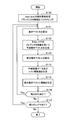
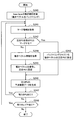
- FIG. 7 is a flowchart showing an example of the flow of motion search processing by the motion search unit 40 according to the present embodiment.
- the motion search unit 40 performs motion search processing of the base layer (step S110).
- the arrangement of prediction units in each coding unit is determined, and the best predictor for each prediction unit is selected.
- the predictor information buffer 147 buffers predictor information indicating the optimum predictor of each prediction unit as setting information.
- steps S111 to S117 are motion search processes of the enhancement layer. Among these processes, the processes of steps S111 to S116 are repeated for each prediction unit of each enhancement layer (hereinafter, referred to as a target PU).
- a target PU each prediction unit of each enhancement layer
- the “upper layer” is a layer to be predicted
- the “lower layer” is a layer lower than the layer to be predicted.
- the motion vector calculation unit 142 calculates a motion vector for one target PU of the upper layer based on the pixel value of the original image and the pixel value of the reference image input from the frame memory 25 (step S111). . Then, the motion vector calculation unit 142 outputs the calculated motion vector to the motion vector prediction unit 143 and the motion vector buffer 144.
- the motion vector prediction unit 143 uses the predictor information for the corresponding PU in the lower layer stored in the predictor information buffer 147, and the reference motion vector acquired according to the predictor information, to obtain the PU of interest.
- a predicted motion vector is generated (step S112).
- the motion vector prediction unit 143 calculates a differential motion vector by subtracting a predicted motion vector from the motion vector (step S113). Then, the motion vector prediction unit 143 outputs the motion vector and the differential motion vector for the attention PU to the mode selection unit 145.
- the mode selection unit 145 generates predicted image data and a cost function value for the attention PU (step S114). Further, the information generation unit 146 generates difference motion vector information indicating a difference motion vector for the attention PU (step S115).
- step S116 when there is an unprocessed PU remaining in the layer to be predicted, the process returns to step S111 (step S116).
- step S117 if no unprocessed PU remains, it is determined whether there is a remaining layer (upper layer) (step S117).
- the processing to be performed after step S111 is repeated with the layer to be predicted up to that point as the lower layer and the next layer as the upper layer.
- Predictor information indicating the predictor selected for the lower layer is subsequently buffered by the predictor information buffer 147. If there are no remaining layers, the motion search process of FIG. 7 ends.
- the predicted image data generated here and the information on inter prediction (which may include differential motion vector information) may be output to the subtractor 13 and the lossless encoder 16 through the selector 27.
- predictor information is not encoded as information on inter prediction in the upper layer, and predictor information in the lower layer is reused, so the code amount of information on inter prediction is reduced. Can.
- FIG. 8 is a block diagram showing an example of a detailed configuration of the motion search unit 40 according to the second embodiment.
- the motion search unit 40 includes a search control unit 241, a motion vector calculation unit 242, a motion vector prediction unit 243, a motion vector buffer 244, a mode selection unit 245, and an information generation unit 246.
- the motion search process of the base layer according to the present embodiment may be the same as the motion search process of the base layer according to the first embodiment described above. However, in the present embodiment, predictor information of the base layer may not be buffered, and motion vector information of the base layer may be buffered across layers.
- the search control unit 241 arranges one or more prediction units in the coding unit, and causes the motion vector calculation unit 242 to calculate a motion vector for each prediction unit.
- the motion vector calculated by the motion vector calculation unit 242 is output to the motion vector prediction unit 243 and stored in the motion vector buffer 244.
- the motion vector prediction unit 243 generates a prediction motion vector using the reference motion vector stored in the motion vector buffer 244 according to each of the plurality of predictor candidates. Then, the motion vector prediction unit 243 calculates a differential motion vector that is the difference between the motion vector calculated by the motion vector calculation unit 242 and the predicted motion vector.
- the mode selection unit 245 generates predicted image data using the motion vector calculated by the motion vector calculation unit 242, and evaluates a cost function value calculated based on comparison between the generated predicted image data and the original image data. Do. Then, the mode selection unit 245 selects the arrangement of the optimum prediction unit that minimizes the cost function value and the optimum predictor for each prediction unit.
- the information generation unit 246 generates information on inter prediction including predictor information indicating an optimal predictor selected for each prediction unit and difference motion vector information indicating a corresponding difference motion vector. Then, the information generation unit 246 outputs the generated information on the inter prediction, the cost function value, and the predicted image data to the selector 27.
- the predictor candidate searched in the motion search process of the base layer according to the present embodiment may include one or both of the above-described spatial predictor and temporal predictor. Furthermore, in the motion search process of the enhancement layer according to the present embodiment, additional predictor candidates are introduced. Predictor candidates introduced here are predictor candidates that use a motion vector set in a corresponding prediction unit of a lower layer as a reference motion vector. Such a predictor is referred to herein as an inter-layer predictor.
- FIG. 9 is an explanatory diagram for describing an example of the inter-layer predictor.
- a prediction unit PTe in the layer L12 which is an upper layer
- a prediction motion vector PMVe of the prediction unit PTe are shown.
- the prediction unit PTbase in the layer L11 which is the lower layer, is a prediction unit corresponding to the prediction unit PTe.
- the reference motion vector MVbase is a motion vector set in the prediction unit PTbase.
- the inter-layer predictor can be expressed, for example, by the following equation (8).
- the motion vector expanded as in the following equation according to the ratio N of the spatial resolution between the lower layer and the upper layer is an inter-layer predictor. It may be used. In that case, the values of the vertical component and the horizontal component of the inter-layer predictor may be rounded so as to match the precision (for example, 1 ⁇ 4 pixel precision, etc.) of the motion vector of the upper layer.
- the selection of an optimal predictor from a plurality of predictor candidates is performed also in the motion search process of the enhancement layer.
- the search control unit 241 causes the motion vector calculation unit 242 to calculate a motion vector for each prediction unit in the coding unit.
- the motion vector calculated by the motion vector calculation unit 242 is output to the motion vector prediction unit 243 and stored in the motion vector buffer 244.
- the motion vector buffer 244 also stores the motion vector (reference motion vector) calculated for each prediction unit of the lower layer.
- the motion vector prediction unit 243 generates a prediction motion vector using the reference motion vector stored in the motion vector buffer 244 according to each of the plurality of predictor candidates.
- the plurality of predictor candidates here include the inter-layer predictors described above.
- the motion vector prediction unit 243 calculates a differential motion vector that is the difference between the motion vector calculated by the motion vector calculation unit 242 and the predicted motion vector.
- the mode selection unit 245 generates predicted image data using the motion vector calculated by the motion vector calculation unit 242, and evaluates a cost function value calculated based on comparison between the generated predicted image data and the original image data. Do. Then, the mode selection unit 245 selects an optimum predictor for each prediction unit.
- the information generation unit 246 generates information on inter prediction including predictor information indicating an optimal predictor selected for each prediction unit and difference motion vector information indicating a corresponding difference motion vector. If the above-described inter-layer predictor is selected as the optimal predictor, the predictor information may include an index specifying the reference motion vector of the lower layer. Then, the information generation unit 246 outputs the generated information on the inter prediction, the cost function value, and the predicted image data to the selector 27.
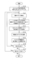
- FIG. 10 is a flowchart showing an example of the flow of motion search processing by the motion search unit 40 according to the present embodiment.
- the motion search unit 40 performs motion search processing of the base layer (step S120).
- the arrangement of prediction units in each coding unit is determined, and the best predictor for each prediction unit is selected.
- the motion vector buffer 244 buffers the motion vector calculated for each prediction unit.
- steps S121 to S127 are motion search processes of the enhancement layer. Among these processes, the processes of steps S121 to S126 are repeated for each focused PU of each enhancement layer.
- the “upper layer” is a layer to be predicted
- the “lower layer” is a layer lower than the layer to be predicted.
- the motion vector calculation unit 242 calculates a motion vector for one target PU of the upper layer based on the pixel value of the original image and the pixel value of the reference image input from the frame memory 25 (step S121). . Then, the motion vector calculation unit 242 outputs the calculated motion vector to the motion vector prediction unit 243 and the motion vector buffer 244.
- the motion vector prediction unit 243 generates a predicted motion vector for the target PU using the reference motion vector stored in the motion vector buffer 244 according to each of the plurality of predictor candidates (step S122).
- the plurality of predictor candidates here include inter-layer predictors.
- the motion vector prediction unit 243 calculates a differential motion vector for each of the plurality of predictor candidates (step S123). Then, the motion vector prediction unit 243 outputs the motion vector and the differential motion vector for each predictor candidate to the mode selection unit 245.
- the mode selection unit 245 generates predicted image data for each predictor candidate, and evaluates the cost function value to select an optimal predictor (step S124). Then, the information generation unit 246 generates predictor information indicating the selected optimum predictor and differential motion vector information indicating the corresponding differential motion vector (step S125).
- step S126 when there is an unprocessed PU remaining in the layer to be predicted, the process returns to step S121 (step S126).
- step S127 if no unprocessed PU remains, it is determined whether there is a remaining layer (upper layer) (step S127). If there is a remaining layer, The processing of step S121 and subsequent steps is repeated with the layer to be predicted up to that point as the lower layer and the next layer as the upper layer.
- the motion vector calculated for each target PU of the lower layer is buffered by the motion vector buffer 244. If there is no remaining layer, the motion search process of FIG. 10 ends.
- the prediction image data generated here and information on inter prediction (which may include predictor information and differential motion vector information) may be output to the subtraction unit 13 and the lossless encoding unit 16 via the selector 27.
- predictor information indicating that an inter-layer predictor based on a motion vector set in a lower layer should be used may be encoded as information on inter prediction in the upper layer.
- the lossless encoding unit 16 that encodes predictor information may assign a minimum code number to an inter-layer predictor among a plurality of predictor candidates in encoding of predictor information of the upper layer.
- the correlation of motion between layers is stronger than the spatial correlation of motion and the temporal correlation of motion. Therefore, by assigning the minimum code number to the inter-layer predictor, it is possible to use more shorter code words in the coded stream after variable-length coding, thereby further reducing the code amount.
- FIG. 11 is a block diagram showing an example of a detailed configuration of the motion search unit 40 according to the third embodiment.
- the motion search unit 40 includes a search control unit 341, a motion vector calculation unit 342, a motion vector buffer 344, a mode selection unit 345, an information generation unit 346, and a merge information buffer 347.
- the search control unit 341 arranges one or more prediction units in the coding unit, and causes the motion vector calculation unit 342 to calculate a motion vector for each prediction unit.
- the motion vector calculated by the motion vector calculation unit 342 is output to the mode selection unit 345 and stored in the motion vector buffer 344.
- the mode selection unit 345 merges prediction units when the motion vector calculated by the motion vector calculation unit 342 for a certain prediction unit is common to the reference motion vector set in one or more adjacent prediction units. Decide that. In the approach proposed by the above non-patent document 3, a certain prediction unit can be merged with the upper adjacent prediction unit or the left adjacent prediction unit.
- the mode selection unit 345 may select, for example, as a merge mode, either merging with a prediction unit adjacent above, merging with a prediction unit adjacent to the left, or no merging. Furthermore, the mode selection unit 345 generates predicted image data for each prediction unit, and calculates a cost function value based on the comparison between the generated predicted image data and the original image data.
- the information generation unit 346 generates information on inter prediction including merge information indicating a merge mode for each prediction unit and motion vector information for a prediction unit not merged with another prediction unit. Then, the information generation unit 346 outputs the generated information on inter prediction, the cost function value, and the predicted image data to the selector 27.
- the merge information generated in the present embodiment may include, for example, two flags “MergeFlag” and “MergeLeftFlag”.
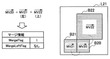
- FIGS. 12A to 12C respectively show examples of merge information that can be generated in this embodiment.
- a prediction unit B20 which is a target PU in the layer L21 is shown.
- the prediction units B21 and B22 are adjacent to the left and above the prediction unit B20, respectively.
- the motion vector MV20 is a motion vector calculated by the motion vector calculation unit 342 for the prediction unit B20.
- the motion vectors MV21 and MV22 are reference motion vectors set in prediction units B21 and B22, respectively.
- the motion vector MV20 is common to both of the reference motion vectors MV21 and MV22.
- MergeLeftFlag is not included in merge information.
- the decoding side that has received such merge information may set a motion vector common to the motion vector set to the prediction unit B21 or B22 to the prediction unit B20 without decoding MergeLeftFlag.
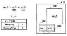
- the motion vector MV20 is common to the reference motion vector MV21 and different from the reference motion vector MV22.
- the decoding side that has received such merge information may set a motion vector common to the motion vector set to the prediction unit B21 to the prediction unit B20.
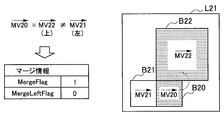
- the motion vector MV20 is common to the reference motion vector MV22 and different from the reference motion vector MV21.
- the decoding side that has received such merge information may set a motion vector common to the motion vector set to the prediction unit B22 to the prediction unit B20.
- Enhancement Layer In the motion search process of the enhancement layer, using the merge information of the lower layer stored in the merge information buffer 347, a motion vector is set to each prediction unit.
- the prediction image data is generated using the motion vector of the prediction unit adjacent to the left, and the cost function value is calculated.
- the mode selection unit 345 generates predicted image data using the motion vector input from the motion vector calculation unit 342, and calculates a cost function value.
- the information generation unit 346 generates information on inter prediction including motion vector information on a prediction unit that is not merged with another prediction unit. Then, the information generation unit 346 outputs the generated information on inter prediction, the cost function value, and the predicted image data to the selector 27.
- FIG. 13 is a flowchart showing an example of the flow of motion search processing by the motion search unit 40 according to the present embodiment.
- the motion search unit 40 performs motion search processing of the base layer (step S130).
- the arrangement of prediction units in each coding unit is determined, and the merge mode of each prediction unit is selected.
- the motion vector buffer 344 buffers the motion vector calculated for each prediction unit.
- the merge information buffer 347 buffers merge information indicating a merge mode selected for each prediction unit as setting information.
- steps S131 to S136 are motion search processes of the enhancement layer. Among these processes, the processes of steps S131 to S135 are repeated for each focused PU of each enhancement layer.
- the “upper layer” is a layer to be predicted
- the “lower layer” is a layer lower than the layer to be predicted.
- the search control unit 341 refers to merge information stored in the merge information buffer 347 as to whether a PU of a corresponding lower layer is merged with another PU for one target PU of the upper layer. It determines (step S131).
- the corresponding lower layer PU is merged with another PU, the PU of interest is also merged with the other PU, and thus the subsequent processing of step S132 is skipped.
- step S132 the motion vector calculation unit 342 calculates a motion vector based on the pixel values of the original image and the pixel values of the reference image input from the frame memory 25 for the target PUs not merged with other PUs ( Step S132). Then, the motion vector calculation unit 342 outputs the calculated motion vector to the mode selection unit 345 and the motion vector buffer 344.
- the mode selection unit 345 generates predicted image data using the motion vector calculated by the motion vector calculation unit 342 or obtained from the motion vector buffer 344 and calculates a cost function value (step S133). Then, the information generation unit 346 generates motion vector information for a target PU that is not merged with another PU (step S134).
- step S135) when there is an unprocessed PU remaining in the layer to be predicted, the process returns to step S131 (step S135).
- step S136 if no unprocessed PU remains, it is determined whether there is a remaining layer (upper layer) (step S136). If there is a remaining layer, Processing from step S131 onward is repeated with the layer to be predicted up to that point as the lower layer and the next layer as the upper layer.
- the motion vector calculated for each target PU of the lower layer is buffered by the motion vector buffer 344.
- the merge information is subsequently buffered by the merge information buffer 347. If there are no remaining layers, the motion search process of FIG. 13 ends.
- the predicted image data and the information on inter prediction generated here can be output to the subtracting unit 13 and the lossless encoding unit 16 via the selector 27.
- merge information is not encoded as information on inter prediction of the upper layer, and merge information of the lower layer is reused, so the code amount of information on inter prediction is reduced. Can.
- FIG. 14 is a block diagram showing an example of a detailed configuration of the motion search unit 40 according to the fourth embodiment.
- the motion search unit 40 includes a search control unit 441, a motion vector calculation unit 442, a motion vector buffer 444, a mode selection unit 445, and an information generation unit 446.
- the motion search process of the base layer according to the present embodiment may be the same as the motion search process of the base layer according to the third embodiment described above. However, in the present embodiment, the merge information of the base layer may not be buffered.
- the search control unit 441 arranges one or more prediction units in the coding unit, and causes the motion vector calculation unit 442 to calculate a motion vector for each prediction unit.
- the motion vector calculated by the motion vector calculation unit 442 is output to the mode selection unit 445 and stored in the motion vector buffer 444.
- the mode selection unit 445 merges prediction units when the motion vector calculated by the motion vector calculation unit 442 for a certain prediction unit is common to the reference motion vector set in one or more adjacent prediction units. Decide that.
- the mode selection unit 445 generates predicted image data for each prediction unit, and calculates a cost function value based on comparison between the generated predicted image data and the original image data.
- the information generation unit 346 generates information on inter prediction including merge information indicating a merge mode for each prediction unit and motion vector information for a prediction unit not merged with another prediction unit. Then, the information generation unit 346 outputs the generated information on inter prediction, the cost function value, and the predicted image data to the selector 27.
- merge information generated in the motion search process of the base layer may include two flags “MergeFlag” and “MergeLeftFlag” similar to those in the third embodiment.
- merge information generated in the motion search process of the enhancement layer may additionally include a new flag "MergeBaseFlag".
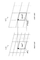
- FIGS. 15A to 15C respectively show examples of merge information that can be generated in this embodiment.
- a prediction unit B30 which is a target PU in the upper layer L30 is shown.
- the prediction units B31 and B32 are adjacent to the left and above the prediction unit B30, respectively.
- the motion vector MV30 is a motion vector calculated by the motion vector calculation unit 442 for the prediction unit B30.
- the motion vectors MV31 and MV32 are reference motion vectors set to prediction units B31 and B32, respectively.
- the prediction unit B20 which is a PU corresponding to the target PU in the lower layer L21, is also shown.
- the motion vector MV20 is a reference motion vector buffered for the prediction unit B20.
- the motion vector MV30 is common to all of the reference motion vectors MV31, MV32 and MV20.
- MergeBaseFlag and MergeLeftFlag are not included in merge information.
- the decoding side having received such merge information may set a motion vector common to the motion vector set to the prediction unit B20, B31 or B32 to a prediction unit B30 without decoding MergeBaseFlag and MergeLeftFlag.
- the motion vector MV30 is common to the reference motion vector MV20 and different from the reference motion vectors MV31 and MV32.
- the decoding side having received such merge information may set a motion vector common to the motion vector set to the prediction unit B20 in the lower layer L21 to the prediction unit B30 in the upper layer L30.
- the motion vector MV30 is common to the reference motion vector MV31 and different from the reference motion vectors MV20 and MV32.
- the decoding side having received such merge information may set a motion vector common to the motion vector set to the prediction unit B31 to the prediction unit B30.
- the search control unit 441 causes the motion vector calculation unit 442 to calculate a motion vector for each prediction unit in the coding unit.
- the motion vector calculated by the motion vector calculation unit 442 is output to the mode selection unit 445 and stored in the motion vector buffer 444.
- the motion vector buffer 444 also stores a motion vector (reference motion vector) calculated for each prediction unit of the lower layer.
- the mode selection unit 445 does not perform these operations. Decide to merge prediction units.
- the mode selection unit 445 selects, for example, merge with the lower layer, merge with the upper adjacent prediction unit, merge with the left adjacent prediction unit, or no merge as the merge mode. obtain. Furthermore, the mode selection unit 445 generates predicted image data for each prediction unit, and calculates a cost function value based on comparison between the generated predicted image data and the original image data.
- the information generation unit 346 generates information on inter prediction including merge information indicating a merge mode for each prediction unit and motion vector information for a prediction unit not merged with another prediction unit. Then, the information generation unit 346 outputs the generated information on inter prediction, the cost function value, and the predicted image data to the selector 27.
- FIG. 16 is a flowchart showing an example of the flow of motion search processing by the motion search unit 40 according to the present embodiment.
- the motion search unit 40 performs motion search processing of the base layer (step S140).
- the arrangement of prediction units in each coding unit is determined, and the merge mode of each prediction unit is selected.
- the motion vector buffer 444 buffers the motion vector calculated for each prediction unit.
- steps S141 to S146 are motion search processes of the enhancement layer. Among these processes, the processes of steps S141 to S145 are repeated for each focused PU of each enhancement layer.
- the “upper layer” is a layer to be predicted
- the “lower layer” is a layer lower than the layer to be predicted.
- the motion vector calculation unit 442 calculates a motion vector for one target PU of the upper layer based on the pixel values of the original image and the pixel values of the reference image input from the frame memory 25 (step S141). . Then, the motion vector calculation unit 442 outputs the calculated motion vector to the mode selection unit 445 and the motion vector buffer 444.
- the mode selection unit 445 selects the merge mode by comparing the motion vector calculated by the motion vector calculation unit 442 with the reference motion vector stored in the motion vector buffer 444 (step S142). For example, if the motion vector calculated for the attention PU is common to the reference motion vector buffered for the corresponding PU in the lower layer, merging with the lower layer may be selected.
- the mode selection unit 445 generates predicted image data using the motion vector for the attention PU, and calculates a cost function value (step S144). Then, the information generation unit 446 generates setting information including merge information on the target PU (and motion vector information on the target PU not merged with other PUs) (step S144).
- step S145 when there is an unprocessed PU remaining in the layer to be predicted, the process returns to step S141 (step S145).
- step S146 if no unprocessed PU remains, it is determined whether there is a remaining layer (upper layer) (step S146). If there is a remaining layer, Processing from step S141 is repeated, with the layer to be predicted up to that point as the lower layer and the next layer as the upper layer.
- the motion vector calculated for each target PU of the lower layer is buffered by the motion vector buffer 444. If there is no remaining layer, the motion search process of FIG. 16 ends.
- the predicted image data and the information on inter prediction generated here can be output to the subtracting unit 13 and the lossless encoding unit 16 via the selector 27.
- merge information indicating that the focused PU is merged with the corresponding PU in the lower layer (the common motion vector is set) as information on inter prediction of the upper layer May be encoded. Therefore, it is possible to merge prediction units with a significantly lower layer of motion correlation, and to effectively reduce the amount of code because motion vectors are not encoded for prediction units in the upper layer to be merged. Can.
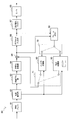
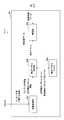
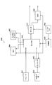
- FIG. 17 is a block diagram showing an example of the configuration of the image decoding apparatus 60 according to an embodiment.
- the image decoding apparatus 60 includes an accumulation buffer 61, a lossless decoding unit 62, an inverse quantization unit 63, an inverse orthogonal transformation unit 64, an addition unit 65, a deblocking filter 66, a rearrangement buffer 67, and D / A (Digital to Analogue) conversion unit 68, frame memory 69, selectors 70 and 71, intra prediction unit 80, and motion compensation unit 90.
- D / A Digital to Analogue
- the accumulation buffer 61 temporarily accumulates the coded stream input through the transmission path.
- the lossless decoding unit 62 decodes the encoded stream input from the accumulation buffer 61 according to the encoding scheme used during encoding. Further, the lossless decoding unit 62 decodes the information multiplexed in the header area of the encoded stream.
- the information multiplexed in the header area of the encoded stream may include, for example, the information on inter prediction described above and the information on intra prediction.
- the lossless decoding unit 62 outputs information on inter prediction to the motion compensation unit 90. In addition, the lossless decoding unit 62 outputs information on intra prediction to the intra prediction unit 80.
- the inverse quantization unit 63 inversely quantizes the quantized data after being decoded by the lossless decoding unit 62.
- the inverse orthogonal transform unit 64 generates prediction error data by performing inverse orthogonal transform on the transform coefficient data input from the dequantization unit 63 according to the orthogonal transform scheme used at the time of encoding. Then, the inverse orthogonal transform unit 64 outputs the generated prediction error data to the addition unit 65.
- the addition unit 65 adds the prediction error data input from the inverse orthogonal transform unit 64 and the prediction image data input from the selector 71 to generate decoded image data. Then, the adding unit 65 outputs the generated decoded image data to the deblocking filter 66 and the frame memory 69.
- the deblocking filter 66 removes block distortion by filtering the decoded image data input from the adding unit 65, and outputs the decoded image data after filtering to the rearrangement buffer 67 and the frame memory 69.
- the rearrangement buffer 67 rearranges the images input from the deblocking filter 66 to generate a series of time-series image data. Then, the rearrangement buffer 67 outputs the generated image data to the D / A converter 68.
- the D / A conversion unit 68 converts the digital format image data input from the rearrangement buffer 67 into an analog format image signal. Then, the D / A conversion unit 68 displays an image, for example, by outputting an analog image signal to a display (not shown) connected to the image decoding device 60.
- the frame memory 69 stores the decoded image data before filtering input from the adding unit 65 and the decoded image data after filtering input from the deblocking filter 66 using a storage medium.
- the selector 70 switches the output destination of the image data from the frame memory 69 between the intra prediction unit 80 and the motion compensation unit 90 for each block in the image according to the mode information acquired by the lossless decoding unit 62. .
- the selector 70 outputs the decoded image data before filtering supplied from the frame memory 69 to the intra prediction unit 80 as reference image data.
- the selector 70 outputs the decoded image data after filtering supplied from the frame memory 69 to the motion compensation unit 90 as reference image data.
- the selector 71 switches the output source of the predicted image data to be supplied to the addition unit 65 between the intra prediction unit 80 and the motion compensation unit 90 according to the mode information acquired by the lossless decoding unit 62. For example, when the intra prediction mode is designated, the selector 71 supplies predicted image data output from the intra prediction unit 80 to the addition unit 65. Further, when the inter prediction mode is designated, the selector 71 supplies predicted image data output from the motion compensation unit 90 to the addition unit 65.
- the intra prediction unit 80 performs intra prediction processing based on the information on intra prediction input from the lossless decoding unit 62 and the reference image data from the frame memory 69, and generates predicted image data. Then, the intra prediction unit 80 outputs the generated predicted image data to the selector 71.
- the motion compensation unit 90 performs motion compensation processing based on the information on inter prediction input from the lossless decoding unit 62 and the reference image data from the frame memory 69 to generate predicted image data.
- the motion compensation processing by the motion compensation unit 90 according to the present embodiment can be realized by extending the method described in the above-mentioned Non-Patent Document 2 or the method described in the above-mentioned Non-Patent Document 3. Then, the motion compensation unit 90 outputs, to the selector 71, predicted image data generated as a result of the motion compensation process. In the next section, four embodiments of the detailed configuration of the motion compensation unit 90 will be described.
- the image decoding device 60 repeats the series of decoding processing described here for each of the plurality of layers of the scalable coded image.
- the first layer to be decoded is the base layer. After the base layer is decoded, one or more enhancement layers are decoded.
- decoding an enhancement layer information obtained by decoding a lower layer, which is a base layer or another enhancement layer, is used.
- a motion vector is set in a prediction unit in a certain upper layer using setting information related to the motion vector set in the corresponding prediction unit in the lower layer.
- the setting information may include, for example, the above-described predictor information, merge information, or motion vector information.
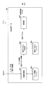
- FIG. 18 is a block diagram showing an example of a detailed configuration of the motion compensation unit 90 according to the first embodiment.
- the motion compensation unit 90 includes an information acquisition unit 191, a motion vector setting unit 192, a predictor information buffer 193, a motion vector buffer 194, and a compensation unit 195.
- the information acquisition unit 191 acquires information on inter prediction to be decoded from the coded stream by the lossless decoding unit 62.
- the information on inter prediction may include predictor information and differential motion vector information (motion vector information for a prediction unit in which no motion vector is predicted).
- the predictor information acquired here indicates, for example, a predictor selected for each prediction unit at the time of encoding among the various predictor candidates described above.
- the motion vector setting unit 192 sets a motion vector for each prediction unit. Then, the motion vector set to each prediction unit by the motion vector setting unit 192 is output to the compensation unit 195 and stored in the motion vector buffer 194.
- predictor information for each prediction unit is temporarily stored in the predictor information buffer 193 for processing in the upper layer.
- the setting of the motion vector by the motion vector setting unit 192 may be performed using a predictor indicated by the predictor information and a difference motion vector indicated by the difference motion vector information for each prediction unit. For example, when the predictor information indicates a spatial predictor as shown in equation (1) for a certain prediction unit, the motion vector setting unit 192 performs motion vector buffer on a reference motion vector of a prediction unit adjacent to the prediction unit. Obtain from 194. Then, the motion vector setting unit 192 substitutes the acquired reference motion vector into Expression (1) to generate a predicted motion vector. Furthermore, the motion vector setting unit 192 reconstructs the motion vector by adding the difference motion vector to the generated predicted motion vector.
- a motion vector reconstructed in this way can be set to each prediction unit.
- the compensation unit 195 generates predicted image data of each prediction unit using the motion vector set in each prediction unit by the motion vector setting unit 192 and the reference image data input from the frame memory 69. Then, the compensation unit 195 outputs the generated predicted image data to the addition unit 65 via the selector 71.
- Enhancement Layer In the motion compensation process of the enhancement layer, prediction of a motion vector is performed based on predictor information of a lower layer stored in the predictor information buffer 193.
- the information acquisition unit 191 acquires information on inter prediction to be decoded from the encoded stream by the lossless decoding unit 62.
- the information on the inter prediction of the enhancement layer may include differential motion vector information (motion vector information for a prediction unit in which prediction of a motion vector is not performed).
- the information acquisition unit 191 is a predictor indicating a predictor used in prediction of a motion vector of a corresponding prediction unit in the lower layer as setting information for setting a motion vector in each prediction unit in the upper layer. Information is obtained from the predictor information buffer 193.
- the predictor information acquired here indicates, for example, any of the spatial predictor or the temporal predictor described above.
- the motion vector setting unit 192 reconstructs a motion vector using the differential motion vector information acquired by the information acquiring unit 191 and the predictor information, and sets the reconstructed motion vector in each prediction unit.
- the motion vector set to each prediction unit by the motion vector setting unit 192 is output to the compensation unit 195 and stored in the motion vector buffer 194.
- the compensation unit 195 generates predicted image data of each prediction unit using the motion vector set in each prediction unit by the motion vector setting unit 192 and the reference image data input from the frame memory 69. Then, the compensation unit 195 outputs the generated predicted image data to the addition unit 65 via the selector 71.
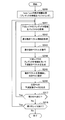
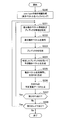
- FIG. 19 is a flowchart showing an example of the flow of motion compensation processing by the motion compensation unit 90 according to the present embodiment.
- the motion compensation unit 90 performs motion compensation processing of the base layer (step S210).
- the predictor information buffer 193 buffers, as setting information, predictor information indicating a predictor selected in encoding for each prediction unit.
- steps S211 to S218 is motion compensation processing of the enhancement layer. Among these processes, the processes of steps S211 to S217 are repeated for each focused PU of each enhancement layer.
- the “upper layer” is a layer to be predicted
- the “lower layer” is a layer lower than the layer to be predicted.
- the information acquisition unit 191 sets one PU of the upper layer as the attention PU, and acquires predictor information on the PU in the lower layer corresponding to the attention PU from the predictor information buffer 193 (step S211). Further, the information acquisition unit 191 acquires differential motion vector information on the attention PU (step S212). The motion vector setting unit 192 decodes the differential motion vector information (step S213).
- the motion vector setting unit 192 generates a predicted motion vector for the attention PU using the predictor information and the reference motion vector acquired by the information acquisition unit 191 (step S214).
- the motion vector setting unit 192 reconstructs the motion vector by adding the difference motion vector to the generated predicted motion vector (step S215).
- the motion vector reconstructed in this way is set to the attention PU.
- the reconstructed motion vector is temporarily stored in the motion vector buffer 194 for processing in the upper layer.
- motion vector information may be acquired from a coding stream instead of difference motion vector information, and a motion vector may be decoded from the said motion vector information.
- the compensation unit 195 generates predicted image data of the attention PU using the motion vector set to the attention PU by the motion vector setting unit 192 and the reference image data input from the frame memory 69 (step S216). ).
- step S217 when there is an unprocessed PU remaining in the layer to be predicted, the process returns to step S211 (step S217).
- step S218 if no unprocessed PU remains, it is determined whether there is a remaining layer (upper layer) (step S218).
- the processing after step S211 is repeated with the layer to be predicted up to that point as the lower layer and the next layer as the upper layer.
- Predictor information indicating the predictor selected for the lower layer is subsequently buffered by the predictor information buffer 193. If there are no remaining layers, the motion compensation process of FIG. 19 ends.
- the predicted image data generated here can be output to the adding unit 65 via the selector 71.
- FIG. 20 is a block diagram showing an example of a detailed configuration of the motion compensation unit 90 according to the second embodiment.
- the motion compensation unit 90 includes an information acquisition unit 291, a motion vector setting unit 292, a motion vector buffer 294, and a compensation unit 295.
- the motion compensation process of the base layer according to the present embodiment may be the same as the motion compensation process of the base layer according to the first embodiment described above. However, in the present embodiment, predictor information of the base layer may not be buffered, and motion vector information of the base layer may be buffered across layers.
- the information acquisition unit 291 acquires information on inter prediction to be decoded from the coded stream by the lossless decoding unit 62.
- the information on inter prediction may include predictor information and differential motion vector information (motion vector information for a prediction unit in which no motion vector is predicted).
- Predictor information acquired here indicates, for example, a predictor selected for each prediction unit during encoding among predictors that may include the above-described spatial predictor and temporal predictor.
- the motion vector setting unit 292 sets a motion vector for each prediction unit. Then, the motion vector set to each prediction unit by the motion vector setting unit 292 is output to the compensation unit 295 and stored in the motion vector buffer 294.
- the setting of motion vectors by the motion vector setting unit 292 may be performed using a predictor indicated by predictor information and a difference motion vector indicated by difference motion vector information for each prediction unit.
- the compensation unit 295 generates predicted image data of each prediction unit using the motion vector set in each prediction unit by the motion vector setting unit 292 and the reference image data input from the frame memory 69. Then, the compensation unit 295 outputs the generated predicted image data to the addition unit 65 via the selector 71.
- motion vector prediction may be performed using an inter-layer predictor based on the reference motion vector of the lower layer stored in the motion vector buffer 294.
- the information acquisition unit 291 acquires information on inter prediction to be decoded from the encoded stream by the lossless decoding unit 62.
- the information on the inter prediction of the enhancement layer includes, as setting information, predictor information indicating a predictor selected in encoding from a plurality of predictor candidates including an inter-layer predictor in addition to the differential motion vector information. obtain. The smallest code number among the plurality of predictor candidates may be assigned to predictor information indicating that the inter-layer predictor has been selected.
- the motion vector setting unit 292 reconstructs a motion vector using the differential motion vector information acquired by the information acquiring unit 291 and the predictor information, and sets the reconstructed motion vector in each prediction unit.
- the motion vector setting unit 292 sets the reference motion vector expanded according to the ratio of the spatial resolution between layers as in the above-described equation (9). , May be a predicted motion vector. At this time, the motion vector setting unit 292 may round the predicted motion vector according to the motion vector accuracy.
- the motion vector set to each prediction unit by the motion vector setting unit 292 is output to the compensation unit 295 and stored in the motion vector buffer 294.
- the compensation unit 295 generates predicted image data of each prediction unit using the motion vector set in each prediction unit by the motion vector setting unit 292 and the reference image data input from the frame memory 69. Then, the compensation unit 295 outputs the generated predicted image data to the addition unit 65 via the selector 71.
- FIG. 21 is a flowchart showing an example of the flow of motion compensation processing by the motion compensation unit 90 according to the present embodiment.
- the motion compensation unit 90 performs motion compensation processing of the base layer (step S220).
- the motion vector buffer 294 buffers the motion vector set for each prediction unit.
- steps S221 to S218 is motion compensation processing of the enhancement layer. Among these processes, the processes of steps S221 to S228 are repeated for each focused PU of each enhancement layer.
- the “upper layer” is a layer to be predicted
- the “lower layer” is a layer lower than the layer to be predicted.
- the information acquisition unit 291 sets one PU of the upper layer as the attention PU, and acquires difference motion vector information and predictor information for the attention PU from the encoded stream (step S221).
- the motion vector setting unit 292 decodes the differential motion vector information (step S222).
- the motion vector setting unit 292 uses predictor information to specify a predictor to be used when generating a predicted motion vector of a focused PU (step S223).
- the motion vector setting unit 292 generates a predicted motion vector for the target PU using the reference motion vector buffered by the motion vector buffer 294 according to the identified predictor (step S224). For example, if the identified predictor is the inter-layer predictor, the motion vector set for the PU in the lower layer corresponding to the PU of interest is the reference motion vector MVbase of equation (8) or equation (9) above. used.
- the motion vector setting unit 292 reconstructs the motion vector by adding the difference motion vector to the generated predicted motion vector (step S225). The motion vector reconstructed in this way is set to the attention PU. Also, the reconstructed motion vector is temporarily stored in the motion vector buffer 294 for processing in the upper layer.
- motion vector information may be acquired from a coding stream instead of difference motion vector information, and a motion vector may be decoded from the said motion vector information.
- the compensation unit 295 generates predicted image data of the attention PU using the motion vector set to the attention PU by the motion vector setting unit 292 and the reference image data input from the frame memory 69 (step S226). ).
- step S221 determines whether there is an unprocessed PU remaining in the layer to be predicted.
- step S2228 determines whether there is a remaining layer (upper layer) (step S228).
- the processing from step S221 is repeated with the layer to be predicted up to that point as the lower layer and the next layer as the upper layer. If there is no remaining layer, the motion compensation process of FIG. 21 ends.
- the predicted image data generated here can be output to the adding unit 65 via the selector 71.
- the motion vector used in the motion compensation of the upper layer can be predicted according to the inter-layer predictor based on the motion vector set in the lower layer. Therefore, as a result of the accuracy of prediction of the motion vector being increased, it is possible to reduce the code amount of the differential motion vector.
- FIG. 22 is a block diagram showing an example of a detailed configuration of the motion compensation unit 90 according to the third embodiment.
- the motion compensation unit 90 includes an information acquisition unit 391, a motion vector setting unit 392, a merge information buffer 393, a motion vector buffer 394, and a compensation unit 395.
- the information acquisition unit 391 acquires information on inter prediction to be decoded from the coded stream by the lossless decoding unit 62.
- information on inter prediction may include merge information and motion vector information.
- the merge information acquired here includes, for example, MergeFlag and MergeLeftFlag described with reference to FIGS. 12A to 12C, and the merge mode selected for each prediction unit at the time of encoding is selected from among a plurality of merge mode candidates. Can be shown.
- the motion vector setting unit 392 sets a motion vector for each prediction unit. Then, the motion vector set to each prediction unit by the motion vector setting unit 392 is output to the compensation unit 395 and stored in the motion vector buffer 394.
- merge information for each prediction unit is stored in the merge information buffer 393 for processing in the upper layer.
- the motion vector setting unit 392 indicates, for example, that merge information indicates that a certain prediction unit is merged with an adjacent prediction unit adjacent to the prediction unit (a motion vector common to these prediction units is set).
- the motion vector set in the adjacent prediction unit is acquired from the motion vector buffer 394, and the acquired motion vector is set in the above-mentioned prediction unit.
- the motion vector setting unit 392 reconstructs by decoding the motion vector information acquired by the information acquisition unit 391. Motion vector is set as the prediction unit.
- the compensation unit 395 generates predicted image data of each prediction unit using the motion vector set in each prediction unit by the motion vector setting unit 392 and the reference image data input from the frame memory 69. Then, the compensation unit 395 outputs the generated predicted image data to the addition unit 65 via the selector 71.
- Enhancement Layer In the motion compensation process of the enhancement layer, a motion vector is set to each prediction unit in accordance with the merge information of the lower layer stored in the merge information buffer 393.
- the information acquisition unit 391 merges information on prediction units in the lower layer corresponding to each prediction unit from the merge information buffer 393 as setting information for setting a motion vector to each prediction unit in the upper layer. get.
- the information acquisition unit 391 acquires motion vector information included in information related to inter prediction for a prediction unit that is not merged with another prediction unit.
- the merge information acquired by the information acquisition unit 391 may include, for example, MergeFlag and MergeLeftFlag described with reference to FIGS. 12A to 12C.
- the motion vector setting unit 392 sets a motion vector in each prediction unit in accordance with the merge information acquired by the information acquisition unit 391.
- the motion vector set to each prediction unit by the motion vector setting unit 392 is output to the compensation unit 395 and stored in the motion vector buffer 394.
- the motion vector setting unit 392 may set, as a prediction unit, a motion vector reconstructed by decoding motion vector information for a prediction unit not merged with another prediction unit.
- the compensation unit 395 generates predicted image data of each prediction unit using the motion vector set in each prediction unit by the motion vector setting unit 392 and the reference image data input from the frame memory 69. Then, the compensation unit 395 outputs the generated predicted image data to the addition unit 65 via the selector 71.
- FIG. 23 is a flowchart showing an example of the flow of motion compensation processing by the motion compensation unit 90 according to the present embodiment.
- the motion compensation unit 90 performs motion compensation processing of the base layer (step S230).
- the merge information buffer 393 buffers, as setting information, merge information indicating a merge mode selected in encoding for each prediction unit.
- steps S231 to S238 is motion compensation processing of the enhancement layer. Among these processes, the processes of steps S231 to S237 are repeated for each focused PU of each enhancement layer.
- the “upper layer” is a layer to be predicted
- the “lower layer” is a layer lower than the layer to be predicted.
- the information acquisition unit 391 sets one PU of the upper layer as the attention PU, and acquires merge information on PUs in the lower layer corresponding to the attention PU from the merge information buffer 393 (step S231).
- the information acquisition unit 391 determines whether to merge the attention PU with another PU based on the acquired merge information (step S232). For example, if the corresponding PU in the lower layer is merged with the left adjacent PU, it may be determined that the PU of interest is also merged with the left adjacent PU. Similarly, if the corresponding PU in the lower layer is merged with the upper adjacent PU, it may be determined that the PU of interest is also merged with the upper adjacent PU. In these cases, the process proceeds to step S233. On the other hand, if the corresponding PU in the lower layer is not merged with the adjacent PU, it may be determined that the PU of interest is also not merged with other PUs. In this case, the process proceeds to step S234.
- step S233 the motion vector setting unit 392 acquires a motion vector identified according to the merge information from the motion vector buffer 394, and sets the acquired motion vector in the attention PU (step S233).
- step S234 the information acquisition unit 391 acquires motion vector information on the attention PU (step S234). Then, the motion vector setting unit 392 decodes the motion vector from the acquired motion vector information, and sets the decoded motion vector to the attention PU (step S235).
- the compensation unit 395 generates predicted image data of the attention PU using the motion vector set to the attention PU by the motion vector setting unit 392 and the reference image data input from the frame memory 69 (step S236). ).
- step S237 when there is an unprocessed PU remaining in the layer to be predicted, the process returns to step S231 (step S237).
- step S238 if no unprocessed PU remains, it is determined whether there is a remaining layer (upper layer) (step S238).
- the processing from step S231 is repeated, with the layer to be predicted up to that point as the lower layer and the next layer as the upper layer.
- Merge information indicating the merge mode selected for the lower layer is subsequently buffered by the merge information buffer 393. If there is no remaining layer, the motion compensation process of FIG. 23 ends.
- the predicted image data generated here can be output to the adding unit 65 via the selector 71.
- the merge information of the lower layer since merge information of the lower layer is reused in decoding of the upper layer, the merge information may not be redundantly encoded for the upper layer. Therefore, the code amount of the information regarding inter prediction can be reduced.
- FIG. 24 is a block diagram showing an example of a detailed configuration of the motion compensation unit 90 according to the fourth embodiment.
- the motion compensation unit 90 includes an information acquisition unit 491, a motion vector setting unit 492, a motion vector buffer 494, and a compensation unit 495.
- the information acquisition unit 491 acquires information on inter prediction to be decoded from the coded stream by the lossless decoding unit 62.
- information on inter prediction may include merge information and motion vector information.
- the merge information acquired for the base layer includes, for example, MergeFlag and MergeLeftFlag described with reference to FIGS. 12A to 12C, and the merge mode selected for each prediction unit during encoding among a plurality of merge mode candidates Can be shown.
- the motion vector setting unit 492 sets a motion vector for each prediction unit. Then, the motion vector set to each prediction unit by the motion vector setting unit 492 is output to the compensation unit 495 and stored in the motion vector buffer 494.
- the motion vector setting unit 492 moves the motion vector of the adjacent prediction unit to a motion vector.
- the motion vector acquired and obtained from the buffer 494 is set as the prediction unit.
- the motion vector setting unit 492 reconstructs by decoding the motion vector information acquired by the information acquisition unit 491. Motion vector is set as the prediction unit.
- the compensation unit 495 generates predicted image data of each prediction unit using the motion vector set in each prediction unit by the motion vector setting unit 492 and the reference image data input from the frame memory 69. Then, the compensation unit 495 outputs the generated predicted image data to the addition unit 65 via the selector 71.
- merge information including MergeBaseFlag indicating merge with a corresponding prediction unit in a lower layer may be used.
- the information acquisition unit 491 acquires information on inter prediction to be decoded from the encoded stream by the lossless decoding unit 62.
- the information on inter prediction for the enhancement layer may include merge information and motion vector information.
- the merge information includes, for example, MergeFlag, MergeBaseFlag, and MergeLeftFlag described with reference to FIGS. 15A to 15C, and can indicate a merge mode selected for each prediction unit at the time of encoding among a plurality of merge mode candidates.
- the motion vector setting unit 492 sets a motion vector in each prediction unit according to the merge information acquired by the information acquisition unit 491.
- the motion vector setting unit 492 sets the buffered motion vectors according to the spatial resolution ratio between layers as in the above-described equation (9). After enlargement, an enlarged motion vector may be set. At this time, the motion vector setting unit 492 may round the enlarged motion vector according to the motion vector accuracy.
- the motion vector set to each prediction unit by the motion vector setting unit 492 is output to the compensation unit 495 and stored in the motion vector buffer 494.
- the motion vector setting unit 492 may set a motion vector reconstructed by decoding motion vector information to a prediction unit that is not merged with another prediction unit.
- the compensation unit 495 generates predicted image data of each prediction unit using the motion vector set in each prediction unit by the motion vector setting unit 492 and the reference image data input from the frame memory 69. Then, the compensation unit 495 outputs the generated predicted image data to the addition unit 65 via the selector 71.
- FIG. 25 is a flow chart showing an example of the flow of motion compensation processing by the motion compensation unit 90 according to the present embodiment.
- the motion compensation unit 90 performs motion compensation processing of the base layer (step S240).
- the motion vector buffer 494 buffers the motion vector set for each prediction unit.
- steps S241 to S248 is motion compensation processing of the enhancement layer. Among these processes, the processes of steps S241 to S247 are repeated for each focused PU of each enhancement layer.
- the “upper layer” is a layer to be predicted
- the “lower layer” is a layer lower than the layer to be predicted.
- the information acquisition unit 491 acquires merge information on one focused PU in the upper layer (step S241).
- the information acquisition unit 491 determines whether to merge the attention PU with another PU, based on the acquired merge information (step S242). For example, the PU of interest may be merged with the corresponding PU in the lower layer or the adjacent PU in the upper layer. If the attention PU is merged with another PU, the process proceeds to step S243. On the other hand, when the attention PU is not merged with another PU, the process proceeds to step S244.
- step S243 the motion vector setting unit 492 acquires a motion vector identified according to the merge information from the motion vector buffer 494, and sets the acquired motion vector in the attention PU (step S243).
- step S244 the information acquisition unit 491 acquires motion vector information on the attention PU (step S244). Then, the motion vector setting unit 492 decodes the motion vector from the acquired motion vector information, and sets the decoded motion vector to the attention PU (step S245).
- the compensation unit 495 generates predicted image data of the attention PU using the motion vector set to the attention PU by the motion vector setting unit 492 and the reference image data input from the frame memory 69 (step S246). ).
- step S247 when there is an unprocessed PU remaining in the layer to be predicted, the process returns to step S241 (step S247).
- step S248 it is determined whether there is a remaining layer (upper layer) (step S248).
- the processing to be performed after step S241 is repeated with the layer to be predicted up to that point as the lower layer and the next layer as the upper layer.
- the motion vector set in each prediction unit of the lower layer is buffered by the motion vector buffer 494. If there are no remaining layers, the motion compensation process of FIG. 25 ends.
- the predicted image data generated here can be output to the adding unit 65 via the selector 71.
- the motion vector in each prediction unit of the enhancement layer Is set. Therefore, since the motion vector is not encoded for the prediction unit in the upper layer merged with the corresponding prediction unit in the lower layer where the motion correlation is remarkable, the code amount can be effectively reduced.
- the image encoding device 10 and the image decoding device 60 according to the embodiments described above are transmitters or receivers for satellite broadcasting, cable broadcasting such as cable TV, distribution over the Internet, distribution to terminals by cellular communication, etc.
- the present invention can be applied to various electronic devices such as a recording device which records an image on a medium such as an optical disk, a magnetic disk and a flash memory, or a reproducing device which reproduces an image from the storage medium.
- a recording device which records an image on a medium such as an optical disk, a magnetic disk and a flash memory
- a reproducing device which reproduces an image from the storage medium.
- FIG. 26 shows an example of a schematic configuration of a television set to which the embodiment described above is applied.
- the television device 900 includes an antenna 901, a tuner 902, a demultiplexer 903, a decoder 904, a video signal processing unit 905, a display unit 906, an audio signal processing unit 907, a speaker 908, an external interface 909, a control unit 910, a user interface 911, And a bus 912.
- the tuner 902 extracts a signal of a desired channel from a broadcast signal received via the antenna 901, and demodulates the extracted signal. Then, the tuner 902 outputs the coded bit stream obtained by demodulation to the demultiplexer 903. That is, the tuner 902 has a role as a transmission means in the television apparatus 900 for receiving a coded stream in which an image is coded.
- the demultiplexer 903 separates the video stream and audio stream of the program to be viewed from the coded bit stream, and outputs the separated streams to the decoder 904. Also, the demultiplexer 903 extracts auxiliary data such as an EPG (Electronic Program Guide) from the encoded bit stream, and supplies the extracted data to the control unit 910. When the coded bit stream is scrambled, the demultiplexer 903 may perform descrambling.
- EPG Electronic Program Guide
- the decoder 904 decodes the video stream and audio stream input from the demultiplexer 903. Then, the decoder 904 outputs the video data generated by the decoding process to the video signal processing unit 905. Further, the decoder 904 outputs the audio data generated by the decoding process to the audio signal processing unit 907.
- the video signal processing unit 905 reproduces the video data input from the decoder 904 and causes the display unit 906 to display a video. Also, the video signal processing unit 905 may cause the display unit 906 to display an application screen supplied via the network. Further, the video signal processing unit 905 may perform additional processing such as noise removal on the video data according to the setting. Furthermore, the video signal processing unit 905 may generate an image of a graphical user interface (GUI) such as a menu, a button, or a cursor, for example, and may superimpose the generated image on the output image.
- GUI graphical user interface
- the display unit 906 is driven by a drive signal supplied from the video signal processing unit 905, and displays a video or an image on the video surface of a display device (for example, a liquid crystal display, a plasma display, or an OLED).
- a display device for example, a liquid crystal display, a plasma display, or an OLED.
- the audio signal processing unit 907 performs reproduction processing such as D / A conversion and amplification on audio data input from the decoder 904, and causes the speaker 908 to output audio. Further, the audio signal processing unit 907 may perform additional processing such as noise removal on the audio data.
- the external interface 909 is an interface for connecting the television device 900 to an external device or a network.
- a video stream or an audio stream received via the external interface 909 may be decoded by the decoder 904. That is, the external interface 909 also serves as a transmission means in the television apparatus 900 for receiving the coded stream in which the image is coded.
- the control unit 910 includes a processor such as a central processing unit (CPU) and memories such as a random access memory (RAM) and a read only memory (ROM).
- the memory stores a program executed by the CPU, program data, EPG data, data acquired via a network, and the like.
- the program stored by the memory is read and executed by the CPU, for example, when the television device 900 is started.
- the CPU controls the operation of the television apparatus 900 according to an operation signal input from, for example, the user interface 911 by executing a program.
- the user interface 911 is connected to the control unit 910.
- the user interface 911 has, for example, buttons and switches for the user to operate the television device 900, a receiver of remote control signals, and the like.
- the user interface 911 detects an operation by the user via these components, generates an operation signal, and outputs the generated operation signal to the control unit 910.
- the bus 912 mutually connects the tuner 902, the demultiplexer 903, the decoder 904, the video signal processing unit 905, the audio signal processing unit 907, the external interface 909, and the control unit 910.
- the decoder 904 has the function of the image decoding device 60 according to the above-described embodiment. Therefore, coding efficiency can be further enhanced by exploiting the correlation of motion between layers in scalable decoding of images in television apparatus 900.
- FIG. 27 shows an example of a schematic configuration of a mobile phone to which the embodiment described above is applied.
- the mobile phone 920 includes an antenna 921, a communication unit 922, an audio codec 923, a speaker 924, a microphone 925, a camera unit 926, an image processing unit 927, a multiplexing and separating unit 928, a recording and reproducing unit 929, a display unit 930, a control unit 931, an operation.
- a unit 932 and a bus 933 are provided.
- the antenna 921 is connected to the communication unit 922.
- the speaker 924 and the microphone 925 are connected to the audio codec 923.
- the operation unit 932 is connected to the control unit 931.
- the bus 933 mutually connects the communication unit 922, the audio codec 923, the camera unit 926, the image processing unit 927, the demultiplexing unit 928, the recording / reproducing unit 929, the display unit 930, and the control unit 931.
- the cellular phone 920 can transmit and receive audio signals, transmit and receive electronic mail or image data, capture an image, and record data in various operation modes including a voice call mode, a data communication mode, a shooting mode, and a videophone mode. Do the action.
- the analog voice signal generated by the microphone 925 is supplied to the voice codec 923.
- the audio codec 923 converts an analog audio signal into audio data, and A / D converts and compresses the converted audio data. Then, the audio codec 923 outputs the compressed audio data to the communication unit 922.
- the communication unit 922 encodes and modulates audio data to generate a transmission signal. Then, the communication unit 922 transmits the generated transmission signal to a base station (not shown) via the antenna 921.
- the communication unit 922 also amplifies and frequency-converts a radio signal received via the antenna 921 to obtain a reception signal.
- the communication unit 922 demodulates and decodes the received signal to generate audio data, and outputs the generated audio data to the audio codec 923.
- the audio codec 923 decompresses and D / A converts audio data to generate an analog audio signal. Then, the audio codec 923 supplies the generated audio signal to the speaker 924 to output audio.
- the control unit 931 generates character data constituting an electronic mail in accordance with an operation by the user via the operation unit 932. Further, the control unit 931 causes the display unit 930 to display characters. Further, the control unit 931 generates electronic mail data in response to a transmission instruction from the user via the operation unit 932, and outputs the generated electronic mail data to the communication unit 922.
- a communication unit 922 encodes and modulates electronic mail data to generate a transmission signal. Then, the communication unit 922 transmits the generated transmission signal to a base station (not shown) via the antenna 921. The communication unit 922 also amplifies and frequency-converts a radio signal received via the antenna 921 to obtain a reception signal.
- the communication unit 922 demodulates and decodes the received signal to restore the e-mail data, and outputs the restored e-mail data to the control unit 931.
- the control unit 931 causes the display unit 930 to display the content of the e-mail, and stores the e-mail data in the storage medium of the recording and reproduction unit 929.
- the recording and reproducing unit 929 includes an arbitrary readable and writable storage medium.
- the storage medium may be a built-in storage medium such as a RAM or a flash memory, or an externally mounted storage medium such as a hard disk, a magnetic disk, a magnetooptical disk, an optical disk, a USB memory, or a memory card. May be
- the camera unit 926 captures an image of a subject to generate image data, and outputs the generated image data to the image processing unit 927.
- the image processing unit 927 encodes the image data input from the camera unit 926, and stores the encoded stream in the storage medium of the recording and reproduction unit 929.
- the demultiplexing unit 928 multiplexes the video stream encoded by the image processing unit 927 and the audio stream input from the audio codec 923, and the communication unit 922 multiplexes the multiplexed stream.
- Output to The communication unit 922 encodes and modulates the stream to generate a transmission signal.
- the communication unit 922 transmits the generated transmission signal to a base station (not shown) via the antenna 921.
- the communication unit 922 also amplifies and frequency-converts a radio signal received via the antenna 921 to obtain a reception signal.
- the transmission signal and the reception signal may include a coded bit stream.
- the communication unit 922 demodulates and decodes the received signal to restore the stream, and outputs the restored stream to the demultiplexing unit 928.
- the demultiplexing unit 928 separates the video stream and the audio stream from the input stream, and outputs the video stream to the image processing unit 927 and the audio stream to the audio codec 923.
- the image processing unit 927 decodes the video stream to generate video data.
- the video data is supplied to the display unit 930, and the display unit 930 displays a series of images.
- the audio codec 923 decompresses and D / A converts the audio stream to generate an analog audio signal. Then, the audio codec 923 supplies the generated audio signal to the speaker 924 to output audio.
- the image processing unit 927 has the functions of the image encoding device 10 and the image decoding device 60 according to the above-described embodiment. Therefore, coding efficiency can be further enhanced by exploiting the correlation of motion between layers in scalable coding and decoding of images in the mobile phone 920.
- FIG. 28 shows an example of a schematic configuration of a recording and reproducing device to which the embodiment described above is applied.
- the recording / reproducing device 940 encodes, for example, audio data and video data of the received broadcast program, and records the encoded data on a recording medium.
- the recording and reproduction device 940 may encode, for example, audio data and video data acquired from another device and record the encoded data on a recording medium.
- the recording / reproducing device 940 reproduces the data recorded on the recording medium on the monitor and the speaker, for example, in accordance with the user's instruction. At this time, the recording / reproducing device 940 decodes the audio data and the video data.
- the recording / reproducing apparatus 940 includes a tuner 941, an external interface 942, an encoder 943, an HDD (Hard Disk Drive) 944, a disk drive 945, a selector 946, a decoder 947, an OSD (On-Screen Display) 948, a control unit 949, and a user interface. And 950.
- the tuner 941 extracts a signal of a desired channel from a broadcast signal received via an antenna (not shown) and demodulates the extracted signal. Then, the tuner 941 outputs the coded bit stream obtained by demodulation to the selector 946. That is, the tuner 941 has a role as a transmission means in the recording / reproducing device 940.
- the external interface 942 is an interface for connecting the recording and reproducing device 940 to an external device or a network.
- the external interface 942 may be, for example, an IEEE 1394 interface, a network interface, a USB interface, or a flash memory interface.
- video data and audio data received via the external interface 942 are input to the encoder 943. That is, the external interface 942 has a role as a transmission unit in the recording / reproducing device 940.
- the encoder 943 encodes video data and audio data when the video data and audio data input from the external interface 942 are not encoded. Then, the encoder 943 outputs the coded bit stream to the selector 946.
- the HDD 944 records an encoded bit stream obtained by compressing content data such as video and audio, various programs, and other data in an internal hard disk. Also, the HDD 944 reads these data from the hard disk when reproducing video and audio.
- the disk drive 945 records and reads data on the attached recording medium.
- the recording medium mounted on the disk drive 945 may be, for example, a DVD disk (DVD-Video, DVD-RAM, DVD-R, DVD-RW, DVD + R, DVD + RW, etc.) or a Blu-ray (registered trademark) disk, etc. .
- the selector 946 selects the coded bit stream input from the tuner 941 or the encoder 943 at the time of recording video and audio, and outputs the selected coded bit stream to the HDD 944 or the disk drive 945. Also, the selector 946 outputs the encoded bit stream input from the HDD 944 or the disk drive 945 to the decoder 947 at the time of reproduction of video and audio.
- the decoder 947 decodes the coded bit stream to generate video data and audio data. Then, the decoder 947 outputs the generated video data to the OSD 948. Also, the decoder 904 outputs the generated audio data to an external speaker.
- the OSD 948 reproduces the video data input from the decoder 947 and displays the video.
- the OSD 948 may superimpose an image of a GUI such as a menu, a button, or a cursor on the video to be displayed.
- the control unit 949 includes a processor such as a CPU, and memories such as a RAM and a ROM.
- the memory stores programs executed by the CPU, program data, and the like.
- the program stored by the memory is read and executed by the CPU, for example, when the recording and reproducing device 940 is started.
- the CPU controls the operation of the recording / reproducing apparatus 940 in accordance with an operation signal input from, for example, the user interface 950 by executing a program.
- the user interface 950 is connected to the control unit 949.
- the user interface 950 includes, for example, buttons and switches for the user to operate the recording and reproducing device 940, a receiver of a remote control signal, and the like.
- the user interface 950 detects an operation by the user via these components, generates an operation signal, and outputs the generated operation signal to the control unit 949.
- the encoder 943 has the function of the image coding apparatus 10 according to the embodiment described above.
- the decoder 947 has the function of the image decoding device 60 according to the above-described embodiment. Therefore, by utilizing the correlation of motion between layers in scalable encoding and decoding of an image in the recording / reproducing apparatus 940, encoding efficiency can be further enhanced.
- FIG. 29 shows an example of a schematic configuration of an imaging device to which the embodiment described above is applied.
- the imaging device 960 captures an object to generate an image, encodes image data, and records the image data in a recording medium.
- the imaging device 960 includes an optical block 961, an imaging unit 962, a signal processing unit 963, an image processing unit 964, a display unit 965, an external interface 966, a memory 967, a media drive 968, an OSD 969, a control unit 970, a user interface 971, and a bus. 972 is provided.
- the optical block 961 is connected to the imaging unit 962.
- the imaging unit 962 is connected to the signal processing unit 963.
- the display unit 965 is connected to the image processing unit 964.
- the user interface 971 is connected to the control unit 970.
- the bus 972 mutually connects the image processing unit 964, the external interface 966, the memory 967, the media drive 968, the OSD 969, and the control unit 970.
- the optical block 961 has a focus lens, an aperture mechanism, and the like.
- the optical block 961 forms an optical image of a subject on the imaging surface of the imaging unit 962.
- the imaging unit 962 includes an image sensor such as a CCD or a CMOS, and converts an optical image formed on an imaging surface into an image signal as an electrical signal by photoelectric conversion. Then, the imaging unit 962 outputs the image signal to the signal processing unit 963.
- the signal processing unit 963 performs various camera signal processing such as knee correction, gamma correction, and color correction on the image signal input from the imaging unit 962.
- the signal processing unit 963 outputs the image data after camera signal processing to the image processing unit 964.
- the image processing unit 964 encodes the image data input from the signal processing unit 963 to generate encoded data. Then, the image processing unit 964 outputs the generated encoded data to the external interface 966 or the media drive 968. The image processing unit 964 also decodes encoded data input from the external interface 966 or the media drive 968 to generate image data. Then, the image processing unit 964 outputs the generated image data to the display unit 965.
- the image processing unit 964 may output the image data input from the signal processing unit 963 to the display unit 965 to display an image. The image processing unit 964 may superimpose the display data acquired from the OSD 969 on the image to be output to the display unit 965.
- the OSD 969 generates an image of a GUI such as a menu, a button, or a cursor, for example, and outputs the generated image to the image processing unit 964.
- a GUI such as a menu, a button, or a cursor
- the external interface 966 is configured as, for example, a USB input / output terminal.
- the external interface 966 connects the imaging device 960 and the printer, for example, when printing an image.
- a drive is connected to the external interface 966 as necessary.
- removable media such as a magnetic disk or an optical disk may be attached to the drive, and a program read from the removable media may be installed in the imaging device 960.
- the external interface 966 may be configured as a network interface connected to a network such as a LAN or the Internet. That is, the external interface 966 has a role as a transmission unit in the imaging device 960.
- the recording medium mounted in the media drive 968 may be, for example, any readable / writable removable medium such as a magnetic disk, a magneto-optical disk, an optical disk, or a semiconductor memory.
- the recording medium may be fixedly attached to the media drive 968, and a non-portable storage unit such as, for example, a built-in hard disk drive or a solid state drive (SSD) may be configured.
- SSD solid state drive
- the control unit 970 includes a processor such as a CPU, and memories such as a RAM and a ROM.
- the memory stores programs executed by the CPU, program data, and the like.
- the program stored by the memory is read and executed by the CPU, for example, when the imaging device 960 starts up.
- the CPU controls the operation of the imaging device 960 according to an operation signal input from, for example, the user interface 971 by executing a program.
- the user interface 971 is connected to the control unit 970.
- the user interface 971 includes, for example, buttons and switches for the user to operate the imaging device 960.
- the user interface 971 detects an operation by the user via these components, generates an operation signal, and outputs the generated operation signal to the control unit 970.
- the image processing unit 964 has the functions of the image encoding device 10 and the image decoding device 60 according to the above-described embodiment. Therefore, coding efficiency can be further enhanced by exploiting the correlation of motion between layers in scalable coding and decoding of images in the imaging device 960.
- FIGS. 1 to 29 four examples of the image encoding device 10 and the image decoding device 60 according to one embodiment have been described using FIGS. 1 to 29.
- it is setting information for setting a motion vector to the second prediction unit in the upper layer corresponding to the first prediction unit in the lower layer at the time of scalable encoding and decoding of an image.
- a motion vector is set to the second prediction unit using setting information related to the motion vector set to the first prediction unit. Therefore, it becomes possible to set a motion vector to each prediction unit of the upper layer by utilizing the correlation of motion between layers. Therefore, since redundant encoding of motion vector information, differential motion vector information, predictor information or merge information is avoided, encoding efficiency can be improved.
- predictor information indicating a predictor used in the prediction of the motion vector of the prediction unit in the lower layer is reused in the prediction of the motion vector of the prediction unit in the upper layer. Be done. Thus, redundant encoding of predictor information can be avoided.
- the inter-layer predictor based on the motion vector set to the corresponding prediction unit in the lower layer for the prediction unit in the upper layer is introduced as a new predictor candidate Be done. Therefore, it is possible to improve the prediction accuracy of the motion vector for the prediction unit in the upper layer, and to reduce the amount of code required to encode the differential motion vector information.
- merge information indicating the merge mode selected for the prediction unit in the lower layer is reused for the prediction unit in the upper layer. Therefore, redundant encoding of merge information can be avoided.
- a new merge mode is introduced in which the corresponding prediction unit in the lower layer and the prediction unit in the upper layer are merged. Therefore, it is possible to avoid redundant coding of motion vector information for prediction units in the upper layer.
- the method of transmitting such information is not limited to such an example.
- the information may be transmitted or recorded as separate data associated with the coded bit stream without being multiplexed into the coded bit stream.
- the term “associate” allows an image (a slice or a block, which may be a part of an image) included in a bitstream to be linked at the time of decoding with information corresponding to the image. Means That is, the information may be transmitted on a different transmission path from the image (or bit stream).
- the information may be recorded on a recording medium (or another recording area of the same recording medium) different from the image (or bit stream).
- the information and the image (or bit stream) may be associated with each other in any unit such as, for example, a plurality of frames, one frame, or a part in a frame.
- a motion vector setting unit configured to set a motion vector in the second prediction unit using the setting information acquired by the information acquisition unit;
- An image processing apparatus comprising: (2)
- the setting information includes predictor information indicating a predictor used in prediction of a motion vector of the first prediction unit, The motion vector setting unit predicts a motion vector set in the second prediction unit, using the predictor indicated by the predictor information.
- the image processing apparatus includes predictor information indicating a predictor used in prediction of a motion vector of the second prediction unit, The predictor is selected from a plurality of predictor candidates including a predictor candidate based on a motion vector set in the first prediction unit, The image processing apparatus according to (1).
- the image processing apparatus according to (3), wherein a smallest code number among the plurality of predictor candidates is assigned to a predictor candidate based on a motion vector set in the first prediction unit.
- the information acquisition unit further acquires difference motion vector information indicating a difference between a motion vector set in the second prediction unit and a prediction motion vector.
- the motion vector setting unit sets, as the second prediction unit, a motion vector generated by adding a difference indicated by the difference motion vector information to the predicted motion vector predicted using the predictor.
- the image processing apparatus according to any one of the items (2) to (4).
- the setting information includes merge information indicating whether a motion vector common to the first prediction unit and a prediction unit adjacent to the first prediction unit is set,
- the motion vector setting unit sets a common motion vector to the second prediction unit and a prediction unit adjacent to the second prediction unit according to the merge information.
- the image processing apparatus according to (1).
- the setting information includes merge information indicating whether a motion vector common to the first prediction unit and the second prediction unit is set, When the merge information indicates that a motion vector common to the first prediction unit and the second prediction unit is set, the motion vector setting unit may be configured to use the first prediction unit and the second prediction unit. Setting a common motion vector to the second prediction unit, The image processing apparatus according to (1). (8) The motion vector setting unit enlarges the motion vector set in the first prediction unit according to the ratio of the spatial resolution between the first layer and the second layer, and The image processing apparatus according to any one of (3), (4), and (7), which performs motion vector setting processing for a prediction unit of.
- the first prediction unit is a prediction unit with the largest overlap among prediction units in the first layer overlapping the second prediction unit.
- Image processing apparatus as described.
- Image processing method including: (15) A second layer in the second layer corresponding to a first prediction unit in the first layer of the image to be scalable-decoded including a first layer and a second layer higher than the first layer; Setting information for setting a motion vector in a prediction unit of the frame, the information generating unit generating the setting information related to the motion vector set in the first prediction unit; An encoding unit that encodes the setting information generated by the information generation unit; An image
- Image coding device image processing device
- 246, 346 Information generation unit
- Encoding unit 60
- Image decoding apparatus image processing apparatus 191, 291, 391, 491
- Information acquisition unit 192
- 246, 392, 492 Motion vector setting unit
Abstract
Description
-空間スケーラビリティ:空間解像度あるいは画像サイズが階層化される。
-時間スケーラビリティ:フレームレートが階層化される。
-SNR(Signal to Noise Ratio)スケーラビリティ:SN比が階層化される。
さらに、標準規格で未だ採用されていないものの、ビット深度スケーラビリティ及びクロマフォーマットスケーラビリティもまた議論されている。 Another important technique in the above-described image coding scheme is scalable coding (also referred to as SVC (Scalable Video Coding)). Scalable coding refers to a technology for hierarchically coding a layer transmitting a coarse image signal and a layer transmitting a fine image signal. The following three types of typical attributes are layered in scalable coding.
-Spatial scalability: spatial resolution or image size is layered.
-Temporal scalability: Frame rates are layered.
-Signal to Noise Ratio (SNR) scalability: SN ratios are layered.
Furthermore, although not yet adopted in the standard, bit depth scalability and chroma format scalability are also discussed.
1.画像符号化装置の構成例
2.動き探索部の詳細な構成例
2-1.第1の実施例
2-2.第2の実施例
2-3.第3の実施例
2-4.第4の実施例
3.画像復号装置の構成例
4.動き補償部の詳細な構成例
4-1.第1の実施例
4-2.第2の実施例
4-3.第3の実施例
4-4.第4の実施例
5.応用例
6.まとめ Also, the description will be made in the following order.
1. Configuration Example of Image Encoding Device Detailed Configuration Example of Motion Search Unit 2-1. First embodiment 2-2. Second embodiment 2-3. Third embodiment 2-4. Fourth Embodiment Configuration Example of Image Decoding Device Detailed Configuration Example of Motion Compensator 4-1. First embodiment 4-2. Second embodiment 4-3. Third Example 4-4. Fourth Example Application example 6. Summary
図1は、一実施形態に係る画像符号化装置10の構成の一例を示すブロック図である。図1を参照すると、画像符号化装置10は、A/D(Analogue to Digital)変換部11、並び替えバッファ12、減算部13、直交変換部14、量子化部15、可逆符号化部16、蓄積バッファ17、レート制御部18、逆量子化部21、逆直交変換部22、加算部23、デブロックフィルタ24、フレームメモリ25、セレクタ26及び27、イントラ予測部30、並びに動き探索部40を備える。 <1. Configuration Example of Image Encoding Device>
FIG. 1 is a block diagram showing an example of the configuration of an
本節では、図1に示した動き探索部40の詳細な構成についての4つの実施例を説明する。その4つの実施例のうち、第1及び第2の実施例は、上記非特許文献2に記載された手法の拡張についての実施例である。一方、第3及び第4の実施例は、上記非特許文献3に記載された手法の拡張についての実施例である。 <2. Detailed Configuration Example of Motion Search Unit>
In this section, four examples of the detailed configuration of the
図4は、第1の実施例に係る動き探索部40の詳細な構成の一例を示すブロック図である。図4を参照すると、動き探索部40は、探索制御部141、動きベクトル算出部142、動きベクトル予測部143、動きベクトルバッファ144、モード選択部145、情報生成部146及びプレディクタ情報バッファ147を有する。 [2-1. First embodiment]
FIG. 4 is a block diagram showing an example of a detailed configuration of the
ベースレイヤの動き探索処理において、探索制御部141は、符号化単位内に1つ以上の予測単位を配置し、各予測単位について動きベクトル算出部142に動きベクトルを算出させる。動きベクトル算出部142により算出された動きベクトルは、動きベクトル予測部143へ出力されると共に、動きベクトルバッファ144に記憶される。動きベクトル予測部143は、複数のプレディクタ候補の各々に従い、動きベクトルバッファ144に記憶されている他のブロックの動きベクトル(参照動きベクトルという)を用いて予測動きベクトルを生成する。そして、動きベクトル予測部143は、動きベクトル算出部142により算出された動きベクトルと予測動きベクトルとの差分である差分動きベクトルを算出する。モード選択部145は、動きベクトル算出部142により算出された動きベクトルを用いて予測画像データを生成し、生成した予測画像データと原画像データとの比較に基づいて計算されるコスト関数値を評価する。そして、モード選択部145は、コスト関数値を最小にする最適な予測単位の配置と各予測単位についての最適なプレディクタとを選択する。情報生成部146は、各予測単位について選択された最適なプレディクタを示すプレディクタ情報及び対応する差分動きベクトルを示す差分動きベクトル情報を含むインター予測に関する情報を生成する。例えば、プレディクタ情報は、参照動きベクトルを特定するインデックスを含んでもよい。また、プレディクタ情報は、予測式を特定するパラメータを含んでもよい。そして、情報生成部146は、生成したインター予測に関する情報、コスト関数値及び予測画像データをセレクタ27へ出力する。また、情報生成部146により生成されるプレディクタ情報は、上位レイヤでの処理のために、プレディクタ情報バッファ147に一時的に記憶される。 (1) Base Layer In the motion search process of the base layer, the


エンハンスメントレイヤの動き探索処理では、プレディクタ情報バッファ147に記憶されている下位レイヤのプレディクタ情報に基づく動きベクトルの予測が行われる。 (2) Enhancement Layer In the motion search process of the enhancement layer, prediction of a motion vector is performed based on predictor information of a lower layer stored in the
図7は、本実施例に係る動き探索部40による動き探索処理の流れの一例を示すフローチャートである。図7を参照すると。まず、動き探索部40は、ベースレイヤの動き探索処理を行う(ステップS110)。その結果、各符号化単位内の予測単位の配置が決定され、各予測単位の最適なプレディクタが選択される。プレディクタ情報バッファ147は、各予測単位の最適なプレディクタを示すプレディクタ情報を設定情報としてバッファリングする。 (3) Flow of Processing FIG. 7 is a flowchart showing an example of the flow of motion search processing by the
図8は、第2の実施例に係る動き探索部40の詳細な構成の一例を示すブロック図である。図8を参照すると、動き探索部40は、探索制御部241、動きベクトル算出部242、動きベクトル予測部243、動きベクトルバッファ244、モード選択部245及び情報生成部246を有する。 [2-2. Second embodiment]
FIG. 8 is a block diagram showing an example of a detailed configuration of the
本実施例に係るベースレイヤの動き探索処理は、上述した第1の実施例に係るベースレイヤの動き探索処理と同様であってよい。但し、本実施例では、ベースレイヤのプレディクタ情報はバッファリングされなくてよく、ベースレイヤの動きベクトル情報がレイヤをまたいでバッファリングされる。ベースレイヤの動き探索処理において、探索制御部241は、符号化単位内に1つ以上の予測単位を配置し、各予測単位について動きベクトル算出部242に動きベクトルを算出させる。動きベクトル算出部242により算出された動きベクトルは、動きベクトル予測部243へ出力されると共に、動きベクトルバッファ244に記憶される。動きベクトル予測部243は、複数のプレディクタ候補の各々に従い、動きベクトルバッファ244に記憶されている参照動きベクトルを用いて予測動きベクトルを生成する。そして、動きベクトル予測部243は、動きベクトル算出部242により算出された動きベクトルと予測動きベクトルとの差分である差分動きベクトルを算出する。モード選択部245は、動きベクトル算出部242により算出された動きベクトルを用いて予測画像データを生成し、生成した予測画像データと原画像データとの比較に基づいて計算されるコスト関数値を評価する。そして、モード選択部245は、コスト関数値を最小にする最適な予測単位の配置と各予測単位についての最適なプレディクタとを選択する。情報生成部246は、各予測単位について選択された最適なプレディクタを示すプレディクタ情報及び対応する差分動きベクトルを示す差分動きベクトル情報を含むインター予測に関する情報を生成する。そして、情報生成部246は、生成したインター予測に関する情報、コスト関数値及び予測画像データをセレクタ27へ出力する。 (1) Base Layer The motion search process of the base layer according to the present embodiment may be the same as the motion search process of the base layer according to the first embodiment described above. However, in the present embodiment, predictor information of the base layer may not be buffered, and motion vector information of the base layer may be buffered across layers. In the motion search process of the base layer, the
本実施例に係るベースレイヤの動き探索処理において探索されるプレディクタ候補は、上述した空間的プレディクタ及び時間的プレディクタの一方又は双方を含んでよい。さらに、本実施例に係るエンハンスメントレイヤの動き探索処理では、追加的なプレディクタ候補が導入される。ここで導入されるプレディクタ候補は、下位レイヤの対応する予測単位に設定された動きベクトルを参照動きベクトルとするプレディクタ候補である。このようなプレディクタを、本明細書では、レイヤ間プレディクタという。 (2) Enhancement Layer The predictor candidate searched in the motion search process of the base layer according to the present embodiment may include one or both of the above-described spatial predictor and temporal predictor. Furthermore, in the motion search process of the enhancement layer according to the present embodiment, additional predictor candidates are introduced. Predictor candidates introduced here are predictor candidates that use a motion vector set in a corresponding prediction unit of a lower layer as a reference motion vector. Such a predictor is referred to herein as an inter-layer predictor.


図10は、本実施例に係る動き探索部40による動き探索処理の流れの一例を示すフローチャートである。図10を参照すると。まず、動き探索部40は、ベースレイヤの動き探索処理を行う(ステップS120)。その結果、各符号化単位内の予測単位の配置が決定され、各予測単位の最適なプレディクタが選択される。動きベクトルバッファ244は、各予測単位について算出された動きベクトルをバッファリングする。 (3) Flow of Processing FIG. 10 is a flowchart showing an example of the flow of motion search processing by the
図11は、第3の実施例に係る動き探索部40の詳細な構成の一例を示すブロック図である。図11を参照すると、動き探索部40は、探索制御部341、動きベクトル算出部342、動きベクトルバッファ344、モード選択部345、情報生成部346及びマージ情報バッファ347を有する。 [2-3. Third embodiment]
FIG. 11 is a block diagram showing an example of a detailed configuration of the
ベースレイヤの動き探索処理において、探索制御部341は、符号化単位内に1つ以上の予測単位を配置し、各予測単位について動きベクトル算出部342に動きベクトルを算出させる。動きベクトル算出部342により算出された動きベクトルは、モード選択部345へ出力されると共に、動きベクトルバッファ344に記憶される。モード選択部345は、ある予測単位について動きベクトル算出部342により算出された動きベクトルが隣接する1つ以上の予測単位に設定された参照動きベクトルと共通である場合に、これら予測単位をマージすることを決定する。上記非特許文献3により提案されている手法では、ある予測単位は、上に隣接する予測単位又は左に隣接する予測単位とマージされ得る。即ち、モード選択部345は、例えば、マージモードとして、上に隣接する予測単位とのマージ、左に隣接する予測単位とのマージ、又はマージなし、のいずれかを選択し得る。さらに、モード選択部345は、各予測単位について予測画像データを生成し、生成した予測画像データと原画像データとの比較に基づいてコスト関数値を計算する。情報生成部346は、各予測単位についてのマージモードを示すマージ情報と、他の予測単位とマージされない予測単位についての動きベクトル情報とを含むインター予測に関する情報を生成する。そして、情報生成部346は、生成したインター予測に関する情報、コスト関数値及び予測画像データをセレクタ27へ出力する。 (1) Base Layer In the motion search process of the base layer, the
エンハンスメントレイヤの動き探索処理では、マージ情報バッファ347に記憶されている下位レイヤのマージ情報を用いて、各予測単位に動きベクトルが設定される。 (2) Enhancement Layer In the motion search process of the enhancement layer, using the merge information of the lower layer stored in the
図13は、本実施例に係る動き探索部40による動き探索処理の流れの一例を示すフローチャートである。図13を参照すると。まず、動き探索部40は、ベースレイヤの動き探索処理を行う(ステップS130)。その結果、各符号化単位内の予測単位の配置が決定され、各予測単位のマージモードが選択される。動きベクトルバッファ344は、各予測単位について算出された動きベクトルをバッファリングする。マージ情報バッファ347は、各予測単位について選択されたマージモードを示すマージ情報を設定情報としてバッファリングする。 (3) Flow of Processing FIG. 13 is a flowchart showing an example of the flow of motion search processing by the
図14は、第4の実施例に係る動き探索部40の詳細な構成の一例を示すブロック図である。図14を参照すると、動き探索部40は、探索制御部441、動きベクトル算出部442、動きベクトルバッファ444、モード選択部445及び情報生成部446を有する。 [2-4. Fourth Embodiment]
FIG. 14 is a block diagram showing an example of a detailed configuration of the
本実施例に係るベースレイヤの動き探索処理は、上述した第3の実施例に係るベースレイヤの動き探索処理と同様であってよい。但し、本実施例では、ベースレイヤのマージ情報はバッファリングされなくてよい。ベースレイヤの動き探索処理において、探索制御部441は、符号化単位内に1つ以上の予測単位を配置し、各予測単位について動きベクトル算出部442に動きベクトルを算出させる。動きベクトル算出部442により算出された動きベクトルは、モード選択部445へ出力されると共に、動きベクトルバッファ444に記憶される。モード選択部445は、ある予測単位について動きベクトル算出部442により算出された動きベクトルが隣接する1つ以上の予測単位に設定された参照動きベクトルと共通である場合に、これら予測単位をマージすることを決定する。モード選択部445は、各予測単位について予測画像データを生成し、生成した予測画像データと原画像データとの比較に基づいてコスト関数値を計算する。情報生成部346は、各予測単位についてのマージモードを示すマージ情報と、他の予測単位とマージされない予測単位についての動きベクトル情報とを含むインター予測に関する情報を生成する。そして、情報生成部346は、生成したインター予測に関する情報、コスト関数値及び予測画像データをセレクタ27へ出力する。 (1) Base Layer The motion search process of the base layer according to the present embodiment may be the same as the motion search process of the base layer according to the third embodiment described above. However, in the present embodiment, the merge information of the base layer may not be buffered. In the motion search process of the base layer, the
本実施例に係るベースレイヤの動き探索処理において生成されるマージ情報は、第3の実施例と同様の「MergeFlag」及び「MergeLeftFlag」という2つのフラグを含んでよい。これに対し、エンハンスメントレイヤの動き探索処理において生成されるマージ情報は、「MergeBaseFlag」という新たなフラグを追加的に含み得る。MergeBaseFlagは、注目PUの動きベクトルが対応する下位レイヤのPUの動きベクトルと共通であるか否かを示すフラグである。例えば、MergeBaseFlag=1の場合、注目PUの動きベクトルは対応する下位レイヤのPUの動きベクトルと共通である。 (2) Enhancement Layer The merge information generated in the motion search process of the base layer according to the present embodiment may include two flags “MergeFlag” and “MergeLeftFlag” similar to those in the third embodiment. On the other hand, merge information generated in the motion search process of the enhancement layer may additionally include a new flag "MergeBaseFlag". MergeBaseFlag is a flag indicating whether or not the motion vector of the attention PU is common to the motion vector of the corresponding lower layer PU. For example, in the case of MergeBaseFlag = 1, the motion vector of the focused PU is common to the motion vector of the corresponding lower layer PU.
図16は、本実施例に係る動き探索部40による動き探索処理の流れの一例を示すフローチャートである。図16を参照すると。まず、動き探索部40は、ベースレイヤの動き探索処理を行う(ステップS140)。その結果、各符号化単位内の予測単位の配置が決定され、各予測単位のマージモードが選択される。動きベクトルバッファ444は、各予測単位について算出された動きベクトルをバッファリングする。 (3) Flow of Processing FIG. 16 is a flowchart showing an example of the flow of motion search processing by the
図17は、一実施形態に係る画像復号装置60の構成の一例を示すブロック図である。図17を参照すると、画像復号装置60は、蓄積バッファ61、可逆復号部62、逆量子化部63、逆直交変換部64、加算部65、デブロックフィルタ66、並び替えバッファ67、D/A(Digital to Analogue)変換部68、フレームメモリ69、セレクタ70及び71、イントラ予測部80、並びに動き補償部90を備える。 <3. Configuration Example of Image Decoding Device>
FIG. 17 is a block diagram showing an example of the configuration of the
本節では、図17に示した動き補償部90の詳細な構成についての4つの実施例を説明する。その4つの実施例は、上述した画像符号化装置10の動き探索部40の4つの実施例にそれぞれ対応する。第1及び第2の実施例は、上記非特許文献2に記載された手法の拡張についての実施例である。一方、第3及び第4の実施例は、上記非特許文献3に記載された手法の拡張についての実施例である。 <4. Detailed Configuration Example of Motion Compensator>
In this section, four embodiments of the detailed configuration of the
図18は、第1の実施例に係る動き補償部90の詳細な構成の一例を示すブロック図である。図18を参照すると、動き補償部90は、情報取得部191、動きベクトル設定部192、プレディクタ情報バッファ193、動きベクトルバッファ194及び補償部195を有する。 [4-1. First embodiment]
FIG. 18 is a block diagram showing an example of a detailed configuration of the
ベースレイヤの動き補償処理において、情報取得部191は、可逆復号部62により符号化ストリームから復号されるインター予測に関する情報を取得する。本実施例において、インター予測に関する情報は、プレディクタ情報及び差分動きベクトル情報(動きベクトルの予測が行われない予測単位については動きベクトル情報)を含み得る。ここで取得されるプレディクタ情報は、例えば、上述した様々なプレディクタ候補のうち符号化の際に各予測単位について選択されたプレディクタを示す。動きベクトル設定部192は、各予測単位に動きベクトルを設定する。そして、動きベクトル設定部192により各予測単位に設定された動きベクトルは、補償部195へ出力されると共に、動きベクトルバッファ194に記憶される。また、各予測単位についてのプレディクタ情報は、上位レイヤでの処理のために、プレディクタ情報バッファ193に一時的に記憶される。動きベクトル設定部192による動きベクトルの設定は、各予測単位についてプレディクタ情報により示されるプレディクタと差分動きベクトル情報により示される差分動きベクトルとを用いて行われ得る。例えば、ある予測単位についてプレディクタ情報が式(1)に示したような空間的プレディクタを示している場合、動きベクトル設定部192は、当該予測単位に隣接する予測単位の参照動きベクトルを動きベクトルバッファ194から取得する。そして、動きベクトル設定部192は、取得した参照動きベクトルを式(1)に代入し、予測動きベクトルを生成する。さらに、動きベクトル設定部192は、生成した予測動きベクトルに差分動きベクトルを加算することにより、動きベクトルを再構築する。このように再構築された動きベクトルが、各予測単位に設定され得る。補償部195は、動きベクトル設定部192により各予測単位に設定された動きベクトルとフレームメモリ69から入力される参照画像データとを用いて、各予測単位の予測画像データを生成する。そして、補償部195は、生成した予測画像データをセレクタ71を介して加算部65へ出力する。 (1) Base Layer In the motion compensation process of the base layer, the information acquisition unit 191 acquires information on inter prediction to be decoded from the coded stream by the
エンハンスメントレイヤの動き補償処理では、プレディクタ情報バッファ193に記憶されている下位レイヤのプレディクタ情報に基づく動きベクトルの予測が行われる。 (2) Enhancement Layer In the motion compensation process of the enhancement layer, prediction of a motion vector is performed based on predictor information of a lower layer stored in the
図19は、本実施例に係る動き補償部90による動き補償処理の流れの一例を示すフローチャートである。図19を参照すると。まず、動き補償部90は、ベースレイヤの動き補償処理を行う(ステップS210)。その際、プレディクタ情報バッファ193は、各予測単位について符号化の際に選択されたプレディクタを示すプレディクタ情報を設定情報としてバッファリングする。 (3) Flow of Processing FIG. 19 is a flowchart showing an example of the flow of motion compensation processing by the
図20は、第2の実施例に係る動き補償部90の詳細な構成の一例を示すブロック図である。図20を参照すると、動き補償部90は、情報取得部291、動きベクトル設定部292、動きベクトルバッファ294及び補償部295を有する。 [4-2. Second embodiment]
FIG. 20 is a block diagram showing an example of a detailed configuration of the
本実施例に係るベースレイヤの動き補償処理は、上述した第1の実施例に係るベースレイヤの動き補償処理と同様であってよい。但し、本実施例では、ベースレイヤのプレディクタ情報はバッファリングされなくてよく、ベースレイヤの動きベクトル情報がレイヤをまたいでバッファリングされる。ベースレイヤの動き補償処理において、情報取得部291は、可逆復号部62により符号化ストリームから復号されるインター予測に関する情報を取得する。本実施例において、インター予測に関する情報は、プレディクタ情報及び差分動きベクトル情報(動きベクトルの予測が行われない予測単位については動きベクトル情報)を含み得る。ここで取得されるプレディクタ情報は、例えば、上述した空間的プレディクタ及び時間的プレディクタを含み得るプレディクタ候補のうち符号化の際に各予測単位について選択されたプレディクタを示す。動きベクトル設定部292は、各予測単位に動きベクトルを設定する。そして、動きベクトル設定部292により各予測単位に設定された動きベクトルは、補償部295へ出力されると共に、動きベクトルバッファ294に記憶される。動きベクトル設定部292による動きベクトルの設定は、各予測単位についてプレディクタ情報により示されるプレディクタと差分動きベクトル情報により示される差分動きベクトルとを用いて行われ得る。補償部295は、動きベクトル設定部292により各予測単位に設定された動きベクトルとフレームメモリ69から入力される参照画像データとを用いて、各予測単位の予測画像データを生成する。そして、補償部295は、生成した予測画像データをセレクタ71を介して加算部65へ出力する。 (1) Base Layer The motion compensation process of the base layer according to the present embodiment may be the same as the motion compensation process of the base layer according to the first embodiment described above. However, in the present embodiment, predictor information of the base layer may not be buffered, and motion vector information of the base layer may be buffered across layers. In the motion compensation process of the base layer, the
エンハンスメントレイヤの動き補償処理では、動きベクトルバッファ294に記憶されている下位レイヤの参照動きベクトルに基づくレイヤ間プレディクタを用いた動きベクトルの予測が行われ得る。 (2) Enhancement Layer In the motion compensation process of the enhancement layer, motion vector prediction may be performed using an inter-layer predictor based on the reference motion vector of the lower layer stored in the
図21は、本実施例に係る動き補償部90による動き補償処理の流れの一例を示すフローチャートである。図21を参照すると。まず、動き補償部90は、ベースレイヤの動き補償処理を行う(ステップS220)。その際、動きベクトルバッファ294は、各予測単位に設定された動きベクトルをバッファリングする。 (3) Flow of Processing FIG. 21 is a flowchart showing an example of the flow of motion compensation processing by the
図22は、第3の実施例に係る動き補償部90の詳細な構成の一例を示すブロック図である。図22を参照すると、動き補償部90は、情報取得部391、動きベクトル設定部392、マージ情報バッファ393、動きベクトルバッファ394及び補償部395を有する。 [4-3. Third embodiment]
FIG. 22 is a block diagram showing an example of a detailed configuration of the
ベースレイヤの動き補償処理において、情報取得部391は、可逆復号部62により符号化ストリームから復号されるインター予測に関する情報を取得する。本実施例において、インター予測に関する情報は、マージ情報及び動きベクトル情報を含み得る。ここで取得されるマージ情報は、例えば、図12A~図12Cを用いて説明したMergeFlag及びMergeLeftFlagを含み、複数のマージモードの候補のうち符号化の際に各予測単位について選択されたマージモードを示し得る。動きベクトル設定部392は、各予測単位に動きベクトルを設定する。そして、動きベクトル設定部392により各予測単位に設定された動きベクトルは、補償部395へ出力されると共に、動きベクトルバッファ394に記憶される。また、各予測単位についてのマージ情報は、上位レイヤでの処理のために、マージ情報バッファ393に記憶される。動きベクトル設定部392は、例えば、ある予測単位が当該予測単位に隣接する隣接予測単位とマージされること(これら予測単位に共通する動きベクトルが設定されること)をマージ情報が示している場合には、隣接予測単位に設定された動きベクトルを動きベクトルバッファ394から取得し、取得した動きベクトルを上記予測単位に設定する。一方、動きベクトル設定部392は、ある予測単位が他の予測単位とマージされないことをマージ情報が示している場合には、情報取得部391により取得された動きベクトル情報を復号することにより再構築される動きベクトルを上記予測単位に設定する。補償部395は、動きベクトル設定部392により各予測単位に設定された動きベクトルとフレームメモリ69から入力される参照画像データとを用いて、各予測単位の予測画像データを生成する。そして、補償部395は、生成した予測画像データをセレクタ71を介して加算部65へ出力する。 (1) Base Layer In the motion compensation process of the base layer, the
エンハンスメントレイヤの動き補償処理では、マージ情報バッファ393に記憶されている下位レイヤのマージ情報に従って、各予測単位に動きベクトルが設定される。 (2) Enhancement Layer In the motion compensation process of the enhancement layer, a motion vector is set to each prediction unit in accordance with the merge information of the lower layer stored in the
図23は、本実施例に係る動き補償部90による動き補償処理の流れの一例を示すフローチャートである。図23を参照すると。まず、動き補償部90は、ベースレイヤの動き補償処理を行う(ステップS230)。その際、マージ情報バッファ393は、各予測単位について符号化の際に選択されたマージモードを示すマージ情報を設定情報としてバッファリングする。 (3) Flow of Processing FIG. 23 is a flowchart showing an example of the flow of motion compensation processing by the
図24は、第4の実施例に係る動き補償部90の詳細な構成の一例を示すブロック図である。図24を参照すると、動き補償部90は、情報取得部491、動きベクトル設定部492、動きベクトルバッファ494及び補償部495を有する。 [4-4. Fourth Embodiment]
FIG. 24 is a block diagram showing an example of a detailed configuration of the
ベースレイヤの動き補償処理において、情報取得部491は、可逆復号部62により符号化ストリームから復号されるインター予測に関する情報を取得する。本実施例において、インター予測に関する情報は、マージ情報及び動きベクトル情報を含み得る。ベースレイヤについて取得されるマージ情報は、例えば、図12A~図12Cを用いて説明したMergeFlag及びMergeLeftFlagを含み、複数のマージモードの候補のうち符号化の際に各予測単位について選択されたマージモードを示し得る。動きベクトル設定部492は、各予測単位に動きベクトルを設定する。そして、動きベクトル設定部492により各予測単位に設定された動きベクトルは、補償部495へ出力されると共に、動きベクトルバッファ494に記憶される。動きベクトル設定部492は、例えば、ある予測単位が当該予測単位に隣接する隣接予測単位とマージされることをマージ情報が示している場合には、隣接予測単位に設定された動きベクトルを動きベクトルバッファ494から取得し、取得した動きベクトルを上記予測単位に設定する。一方、動きベクトル設定部492は、ある予測単位が他の予測単位とマージされないことをマージ情報が示している場合には、情報取得部491により取得された動きベクトル情報を復号することにより再構築される動きベクトルを上記予測単位に設定する。補償部495は、動きベクトル設定部492により各予測単位に設定された動きベクトルとフレームメモリ69から入力される参照画像データとを用いて、各予測単位の予測画像データを生成する。そして、補償部495は、生成した予測画像データをセレクタ71を介して加算部65へ出力する。 (1) Base Layer In the motion compensation process of the base layer, the
エンハンスメントレイヤの動き補償処理では、下位レイヤ内の対応する予測単位とのマージを示すMergeBaseFlagを含むマージ情報が利用され得る。 (2) Enhancement Layer In motion compensation processing of an enhancement layer, merge information including MergeBaseFlag indicating merge with a corresponding prediction unit in a lower layer may be used.
図25は、本実施例に係る動き補償部90による動き補償処理の流れの一例を示すフローチャートである。図25を参照すると。まず、動き補償部90は、ベースレイヤの動き補償処理を行う(ステップS240)。その際、動きベクトルバッファ494は、各予測単位に設定された動きベクトルをバッファリングする。 (3) Flow of Processing FIG. 25 is a flow chart showing an example of the flow of motion compensation processing by the
上述した実施形態に係る画像符号化装置10及び画像復号装置60は、衛星放送、ケーブルTVなどの有線放送、インターネット上での配信、及びセルラー通信による端末への配信などにおける送信機若しくは受信機、光ディスク、磁気ディスク及びフラッシュメモリなどの媒体に画像を記録する記録装置、又は、これら記憶媒体から画像を再生する再生装置などの様々な電子機器に応用され得る。以下、4つの応用例について説明する。 <5. Application example>
The
図26は、上述した実施形態を適用したテレビジョン装置の概略的な構成の一例を示している。テレビジョン装置900は、アンテナ901、チューナ902、デマルチプレクサ903、デコーダ904、映像信号処理部905、表示部906、音声信号処理部907、スピーカ908、外部インタフェース909、制御部910、ユーザインタフェース911、及びバス912を備える。 [5-1. First application example]
FIG. 26 shows an example of a schematic configuration of a television set to which the embodiment described above is applied. The
図27は、上述した実施形態を適用した携帯電話機の概略的な構成の一例を示している。携帯電話機920は、アンテナ921、通信部922、音声コーデック923、スピーカ924、マイクロホン925、カメラ部926、画像処理部927、多重分離部928、記録再生部929、表示部930、制御部931、操作部932、及びバス933を備える。 5-2. Second application example]
FIG. 27 shows an example of a schematic configuration of a mobile phone to which the embodiment described above is applied. The
図28は、上述した実施形態を適用した記録再生装置の概略的な構成の一例を示している。記録再生装置940は、例えば、受信した放送番組の音声データ及び映像データを符号化して記録媒体に記録する。また、記録再生装置940は、例えば、他の装置から取得される音声データ及び映像データを符号化して記録媒体に記録してもよい。また、記録再生装置940は、例えば、ユーザの指示に応じて、記録媒体に記録されているデータをモニタ及びスピーカ上で再生する。このとき、記録再生装置940は、音声データ及び映像データを復号する。 5-3. Third application example]
FIG. 28 shows an example of a schematic configuration of a recording and reproducing device to which the embodiment described above is applied. The recording / reproducing
図29は、上述した実施形態を適用した撮像装置の概略的な構成の一例を示している。撮像装置960は、被写体を撮像して画像を生成し、画像データを符号化して記録媒体に記録する。 5-4. Fourth application example]
FIG. 29 shows an example of a schematic configuration of an imaging device to which the embodiment described above is applied. The
ここまで、図1~図29を用いて、一実施形態に係る画像符号化装置10及び画像復号装置60の4つの実施例について説明した。これら実施例によれば、画像のスケーラブル符号化及び復号に際して、下位レイヤ内の第1の予測単位に対応する上位レイヤ内の第2の予測単位に動きベクトルを設定するための設定情報であって、上記第1の予測単位に設定された動きベクトルに関連する設定情報を用いて、上記第2の予測単位に動きベクトルが設定される。従って、レイヤ間の動きの相関を活用して上位レイヤの各予測単位に動きベクトルを設定することが可能となる。よって、動きベクトル情報、差分動きベクトル情報、プレディクタ情報又はマージ情報の冗長な符号化が回避されるため、符号化効率を高めることができる。 <6. Summary>
Up to this point, four examples of the
(1)
第1のレイヤ及び前記第1のレイヤよりも上位の第2のレイヤを含むスケーラブル復号される画像の前記第1のレイヤ内の第1の予測単位に対応する前記第2のレイヤ内の第2の予測単位に動きベクトルを設定するための設定情報であって、前記第1の予測単位に設定された動きベクトルに関連する前記設定情報を取得する情報取得部と、
前記情報取得部により取得される前記設定情報を用いて、前記第2の予測単位に動きベクトルを設定する動きベクトル設定部と、
を備える画像処理装置。
(2)
前記設定情報は、前記第1の予測単位の動きベクトルの予測の際に用いられるプレディクタを示すプレディクタ情報を含み、
前記動きベクトル設定部は、前記プレディクタ情報により示される前記プレディクタを用いて、前記第2の予測単位に設定される動きベクトルを予測する、
前記(1)に記載の画像処理装置。
(3)
前記設定情報は、前記第2の予測単位の動きベクトルの予測の際に用いられるプレディクタを示すプレディクタ情報を含み、
前記プレディクタは、前記第1の予測単位に設定された動きベクトルに基づくプレディクタ候補を含む複数のプレディクタ候補から選択される、
前記(1)に記載の画像処理装置。
(4)
前記第1の予測単位に設定された動きベクトルに基づくプレディクタ候補には、前記複数のプレディクタ候補の中で最小の符号番号が割り当てられる、前記(3)に記載の画像処理装置。
(5)
前記情報取得部は、前記第2の予測単位に設定される動きベクトルと予測動きベクトルとの差分を示す差分動きベクトル情報をさらに取得し、
前記動きベクトル設定部は、前記プレディクタを用いて予測した前記予測動きベクトルに前記差分動きベクトル情報により示される差分を加算することにより生成される動きベクトルを、前記第2の予測単位に設定する、
前記(2)~(4)のいずれか1項に記載の画像処理装置。
(6)
前記設定情報は、前記第1の予測単位と前記第1の予測単位に隣接する予測単位とに共通する動きベクトルが設定されるかを示すマージ情報を含み、
前記動きベクトル設定部は、前記マージ情報に従って、前記第2の予測単位と前記第2の予測単位に隣接する予測単位とに共通の動きベクトルを設定する、
前記(1)に記載の画像処理装置。
(7)
前記設定情報は、前記第1の予測単位と前記第2の予測単位とに共通する動きベクトルが設定されるかを示すマージ情報を含み、
前記動きベクトル設定部は、前記第1の予測単位と前記第2の予測単位とに共通する動きベクトルが設定されることを前記マージ情報が示している場合には、前記第1の予測単位と共通の動きベクトルを前記第2の予測単位に設定する、
前記(1)に記載の画像処理装置。
(8)
前記動きベクトル設定部は、前記第1のレイヤと前記第2のレイヤとの間の空間解像度の比率に応じて前記第1の予測単位に設定された動きベクトルを拡大した上で、前記第2の予測単位について動きベクトル設定処理を行う、前記(3)、(4)及び(7)のいずれか1項に記載の画像処理装置。
(9)
前記動きベクトル設定部は、前記第1の予測単位に設定された動きベクトルの拡大に際して、拡大された動きベクトルを動きベクトル精度に応じて丸める、前記(8)に記載の画像処理装置。
(10)
前記第1のレイヤ及び前記第2のレイヤは、空間解像度の互いに異なるレイヤである、前記(1)~(7)のいずれか1項に記載の画像処理装置。
(11)
前記第1のレイヤ及び前記第2のレイヤは、雑音比率の互いに異なるレイヤである、前記(1)~(7)のいずれか1項に記載の画像処理装置。
(12)
前記第1の予測単位は、前記第2の予測単位内の所定の位置の画素に対応する画素を有する、前記第1のレイヤ内の予測単位である、前記(1)~(11)のいずれか1項に記載の画像処理装置。
(13)
前記第1の予測単位は、前記第2の予測単位と重なる前記第1のレイヤ内の予測単位のうち重なりの最も大きい予測単位である、前記(1)~(11)のいずれか1項に記載の画像処理装置。
(14)
第1のレイヤ及び前記第1のレイヤよりも上位の第2のレイヤを含むスケーラブル復号される画像の前記第1のレイヤ内の第1の予測単位に対応する前記第2のレイヤ内の第2の予測単位に動きベクトルを設定するための設定情報であって、前記第1の予測単位に設定された動きベクトルに関連する前記設定情報を取得することと、
取得された前記設定情報を用いて、前記第2の予測単位に動きベクトルを設定することと、
を含む画像処理方法。
(15)
第1のレイヤ及び前記第1のレイヤよりも上位の第2のレイヤを含むスケーラブル復号される画像の前記第1のレイヤ内の第1の予測単位に対応する前記第2のレイヤ内の第2の予測単位に動きベクトルを設定するための設定情報であって、前記第1の予測単位に設定された動きベクトルに関連する前記設定情報を生成する情報生成部と、
前記情報生成部により生成される前記設定情報を符号化する符号化部と、
を備える画像処理装置。
(16)
第1のレイヤ及び前記第1のレイヤよりも上位の第2のレイヤを含むスケーラブル復号される画像の前記第1のレイヤ内の第1の予測単位に対応する前記第2のレイヤ内の第2の予測単位に動きベクトルを設定するための設定情報であって、前記第1の予測単位に設定された動きベクトルに関連する前記設定情報を生成することと、
生成された前記設定情報を符号化することと、
を含む画像処理方法。 The following configurations are also within the technical scope of the present disclosure.
(1)
A second layer in the second layer corresponding to a first prediction unit in the first layer of the image to be scalable-decoded including a first layer and a second layer higher than the first layer; Setting information for setting a motion vector in a prediction unit of the information, and an information acquisition unit that acquires the setting information related to the motion vector set in the first prediction unit;
A motion vector setting unit configured to set a motion vector in the second prediction unit using the setting information acquired by the information acquisition unit;
An image processing apparatus comprising:
(2)
The setting information includes predictor information indicating a predictor used in prediction of a motion vector of the first prediction unit,
The motion vector setting unit predicts a motion vector set in the second prediction unit, using the predictor indicated by the predictor information.
The image processing apparatus according to (1).
(3)
The setting information includes predictor information indicating a predictor used in prediction of a motion vector of the second prediction unit,
The predictor is selected from a plurality of predictor candidates including a predictor candidate based on a motion vector set in the first prediction unit,
The image processing apparatus according to (1).
(4)
The image processing apparatus according to (3), wherein a smallest code number among the plurality of predictor candidates is assigned to a predictor candidate based on a motion vector set in the first prediction unit.
(5)
The information acquisition unit further acquires difference motion vector information indicating a difference between a motion vector set in the second prediction unit and a prediction motion vector.
The motion vector setting unit sets, as the second prediction unit, a motion vector generated by adding a difference indicated by the difference motion vector information to the predicted motion vector predicted using the predictor.
The image processing apparatus according to any one of the items (2) to (4).
(6)
The setting information includes merge information indicating whether a motion vector common to the first prediction unit and a prediction unit adjacent to the first prediction unit is set,
The motion vector setting unit sets a common motion vector to the second prediction unit and a prediction unit adjacent to the second prediction unit according to the merge information.
The image processing apparatus according to (1).
(7)
The setting information includes merge information indicating whether a motion vector common to the first prediction unit and the second prediction unit is set,
When the merge information indicates that a motion vector common to the first prediction unit and the second prediction unit is set, the motion vector setting unit may be configured to use the first prediction unit and the second prediction unit. Setting a common motion vector to the second prediction unit,
The image processing apparatus according to (1).
(8)
The motion vector setting unit enlarges the motion vector set in the first prediction unit according to the ratio of the spatial resolution between the first layer and the second layer, and The image processing apparatus according to any one of (3), (4), and (7), which performs motion vector setting processing for a prediction unit of.
(9)
The image processing apparatus according to (8), wherein the motion vector setting unit rounds the enlarged motion vector according to the motion vector accuracy when expanding the motion vector set in the first prediction unit.
(10)
The image processing apparatus according to any one of (1) to (7), wherein the first layer and the second layer are layers different from each other in spatial resolution.
(11)
The image processing apparatus according to any one of (1) to (7), wherein the first layer and the second layer are layers different from each other in noise ratio.
(12)
Any of the above (1) to (11), which is a prediction unit in the first layer, wherein the first prediction unit has a pixel corresponding to a pixel at a predetermined position in the second prediction unit. An image processing apparatus according to any one of the preceding claims.
(13)
In any one of (1) to (11), the first prediction unit is a prediction unit with the largest overlap among prediction units in the first layer overlapping the second prediction unit. Image processing apparatus as described.
(14)
A second layer in the second layer corresponding to a first prediction unit in the first layer of the image to be scalable-decoded including a first layer and a second layer higher than the first layer; Setting information for setting a motion vector in a prediction unit of the frame, and obtaining the setting information related to the motion vector set in the first prediction unit;
Setting a motion vector in the second prediction unit using the acquired setting information;
Image processing method including:
(15)
A second layer in the second layer corresponding to a first prediction unit in the first layer of the image to be scalable-decoded including a first layer and a second layer higher than the first layer; Setting information for setting a motion vector in a prediction unit of the frame, the information generating unit generating the setting information related to the motion vector set in the first prediction unit;
An encoding unit that encodes the setting information generated by the information generation unit;
An image processing apparatus comprising:
(16)
A second layer in the second layer corresponding to a first prediction unit in the first layer of the image to be scalable-decoded including a first layer and a second layer higher than the first layer; Setting information for setting a motion vector in a prediction unit of the frame, and generating the setting information related to the motion vector set in the first prediction unit;
Encoding the generated configuration information;
Image processing method including:
146,246,346,446 情報生成部
16 符号化部
60 画像復号装置(画像処理装置)
191,291,391,491 情報取得部
192,246,392,492 動きベクトル設定部
10 Image coding device (image processing device)
146, 246, 346, 446
191, 291, 391, 491
Claims (16)
- 第1のレイヤ及び前記第1のレイヤよりも上位の第2のレイヤを含むスケーラブル復号される画像の前記第1のレイヤ内の第1の予測単位に対応する前記第2のレイヤ内の第2の予測単位に動きベクトルを設定するための設定情報であって、前記第1の予測単位に設定された動きベクトルに関連する前記設定情報を取得する情報取得部と、
前記情報取得部により取得される前記設定情報を用いて、前記第2の予測単位に動きベクトルを設定する動きベクトル設定部と、
を備える画像処理装置。 A second layer in the second layer corresponding to a first prediction unit in the first layer of the image to be scalable-decoded including a first layer and a second layer higher than the first layer; Setting information for setting a motion vector in a prediction unit of the information, and an information acquisition unit that acquires the setting information related to the motion vector set in the first prediction unit;
A motion vector setting unit configured to set a motion vector in the second prediction unit using the setting information acquired by the information acquisition unit;
An image processing apparatus comprising: - 前記設定情報は、前記第1の予測単位の動きベクトルの予測の際に用いられるプレディクタを示すプレディクタ情報を含み、
前記動きベクトル設定部は、前記プレディクタ情報により示される前記プレディクタを用いて、前記第2の予測単位に設定される動きベクトルを予測する、
請求項1に記載の画像処理装置。 The setting information includes predictor information indicating a predictor used in prediction of a motion vector of the first prediction unit,
The motion vector setting unit predicts a motion vector set in the second prediction unit, using the predictor indicated by the predictor information.
The image processing apparatus according to claim 1. - 前記設定情報は、前記第2の予測単位の動きベクトルの予測の際に用いられるプレディクタを示すプレディクタ情報を含み、
前記プレディクタは、前記第1の予測単位に設定された動きベクトルに基づくプレディクタ候補を含む複数のプレディクタ候補から選択される、
請求項1に記載の画像処理装置。 The setting information includes predictor information indicating a predictor used in prediction of a motion vector of the second prediction unit,
The predictor is selected from a plurality of predictor candidates including a predictor candidate based on a motion vector set in the first prediction unit,
The image processing apparatus according to claim 1. - 前記第1の予測単位に設定された動きベクトルに基づくプレディクタ候補には、前記複数のプレディクタ候補の中で最小の符号番号が割り当てられる、請求項3に記載の画像処理装置。 The image processing apparatus according to claim 3, wherein a smallest code number among the plurality of predictor candidates is assigned to a predictor candidate based on a motion vector set in the first prediction unit.
- 前記情報取得部は、前記第2の予測単位に設定される動きベクトルと予測動きベクトルとの差分を示す差分動きベクトル情報をさらに取得し、
前記動きベクトル設定部は、前記プレディクタを用いて予測した前記予測動きベクトルに前記差分動きベクトル情報により示される差分を加算することにより生成される動きベクトルを、前記第2の予測単位に設定する、
請求項2に記載の画像処理装置。 The information acquisition unit further acquires difference motion vector information indicating a difference between a motion vector set in the second prediction unit and a prediction motion vector.
The motion vector setting unit sets, as the second prediction unit, a motion vector generated by adding a difference indicated by the difference motion vector information to the predicted motion vector predicted using the predictor.
The image processing apparatus according to claim 2. - 前記設定情報は、前記第1の予測単位と前記第1の予測単位に隣接する予測単位とに共通する動きベクトルが設定されるかを示すマージ情報を含み、
前記動きベクトル設定部は、前記マージ情報に従って、前記第2の予測単位と前記第2の予測単位に隣接する予測単位とに共通の動きベクトルを設定する、
請求項1に記載の画像処理装置。 The setting information includes merge information indicating whether a motion vector common to the first prediction unit and a prediction unit adjacent to the first prediction unit is set,
The motion vector setting unit sets a common motion vector to the second prediction unit and a prediction unit adjacent to the second prediction unit according to the merge information.
The image processing apparatus according to claim 1. - 前記設定情報は、前記第1の予測単位と前記第2の予測単位とに共通する動きベクトルが設定されるかを示すマージ情報を含み、
前記動きベクトル設定部は、前記第1の予測単位と前記第2の予測単位とに共通する動きベクトルが設定されることを前記マージ情報が示している場合には、前記第1の予測単位と共通の動きベクトルを前記第2の予測単位に設定する、
請求項1に記載の画像処理装置。 The setting information includes merge information indicating whether a motion vector common to the first prediction unit and the second prediction unit is set,
When the merge information indicates that a motion vector common to the first prediction unit and the second prediction unit is set, the motion vector setting unit may be configured to use the first prediction unit and the second prediction unit. Setting a common motion vector to the second prediction unit,
The image processing apparatus according to claim 1. - 前記動きベクトル設定部は、前記第1のレイヤと前記第2のレイヤとの間の空間解像度の比率に応じて前記第1の予測単位に設定された動きベクトルを拡大した上で、前記第2の予測単位について動きベクトル設定処理を行う、請求項3に記載の画像処理装置。 The motion vector setting unit enlarges the motion vector set in the first prediction unit according to the ratio of the spatial resolution between the first layer and the second layer, and The image processing apparatus according to claim 3, wherein the motion vector setting process is performed for each prediction unit.
- 前記動きベクトル設定部は、前記第1の予測単位に設定された動きベクトルの拡大に際して、拡大された動きベクトルを動きベクトル精度に応じて丸める、請求項8に記載の画像処理装置。 9. The image processing apparatus according to claim 8, wherein the motion vector setting unit rounds the enlarged motion vector according to the motion vector accuracy when expanding the motion vector set in the first prediction unit.
- 前記第1のレイヤ及び前記第2のレイヤは、空間解像度の互いに異なるレイヤである、請求項1に記載の画像処理装置。 The image processing apparatus according to claim 1, wherein the first layer and the second layer are layers different from each other in spatial resolution.
- 前記第1のレイヤ及び前記第2のレイヤは、雑音比率の互いに異なるレイヤである、請求項1に記載の画像処理装置。 The image processing apparatus according to claim 1, wherein the first layer and the second layer are layers different from each other in noise ratio.
- 前記第1の予測単位は、前記第2の予測単位内の所定の位置の画素に対応する画素を有する、前記第1のレイヤ内の予測単位である、請求項1に記載の画像処理装置。 The image processing apparatus according to claim 1, wherein the first prediction unit is a prediction unit in the first layer that has a pixel corresponding to a pixel at a predetermined position in the second prediction unit.
- 前記第1の予測単位は、前記第2の予測単位と重なる前記第1のレイヤ内の予測単位のうち重なりの最も大きい予測単位である、請求項1に記載の画像処理装置。 The image processing apparatus according to claim 1, wherein the first prediction unit is a prediction unit with the largest overlap among prediction units in the first layer overlapping with the second prediction unit.
- 第1のレイヤ及び前記第1のレイヤよりも上位の第2のレイヤを含むスケーラブル復号される画像の前記第1のレイヤ内の第1の予測単位に対応する前記第2のレイヤ内の第2の予測単位に動きベクトルを設定するための設定情報であって、前記第1の予測単位に設定された動きベクトルに関連する前記設定情報を取得することと、
取得された前記設定情報を用いて、前記第2の予測単位に動きベクトルを設定することと、
を含む画像処理方法。 A second layer in the second layer corresponding to a first prediction unit in the first layer of the image to be scalable-decoded including a first layer and a second layer higher than the first layer; Setting information for setting a motion vector in a prediction unit of the frame, and obtaining the setting information related to the motion vector set in the first prediction unit;
Setting a motion vector in the second prediction unit using the acquired setting information;
Image processing method including: - 第1のレイヤ及び前記第1のレイヤよりも上位の第2のレイヤを含むスケーラブル復号される画像の前記第1のレイヤ内の第1の予測単位に対応する前記第2のレイヤ内の第2の予測単位に動きベクトルを設定するための設定情報であって、前記第1の予測単位に設定された動きベクトルに関連する前記設定情報を生成する情報生成部と、
前記情報生成部により生成される前記設定情報を符号化する符号化部と、
を備える画像処理装置。 A second layer in the second layer corresponding to a first prediction unit in the first layer of the image to be scalable-decoded including a first layer and a second layer higher than the first layer; Setting information for setting a motion vector in a prediction unit of the frame, the information generating unit generating the setting information related to the motion vector set in the first prediction unit;
An encoding unit that encodes the setting information generated by the information generation unit;
An image processing apparatus comprising: - 第1のレイヤ及び前記第1のレイヤよりも上位の第2のレイヤを含むスケーラブル復号される画像の前記第1のレイヤ内の第1の予測単位に対応する前記第2のレイヤ内の第2の予測単位に動きベクトルを設定するための設定情報であって、前記第1の予測単位に設定された動きベクトルに関連する前記設定情報を生成することと、
生成された前記設定情報を符号化することと、
を含む画像処理方法。
A second layer in the second layer corresponding to a first prediction unit in the first layer of the image to be scalable-decoded including a first layer and a second layer higher than the first layer; Setting information for setting a motion vector in a prediction unit of the frame, and generating the setting information related to the motion vector set in the first prediction unit;
Encoding the generated configuration information;
Image processing method including:
Priority Applications (7)
| Application Number | Priority Date | Filing Date | Title |
|---|---|---|---|
| RU2013157386A RU2620719C2 (en) | 2011-07-14 | 2012-05-24 | Image processing device and image processing method |
| EP12811989.8A EP2733943B1 (en) | 2011-07-14 | 2012-05-24 | Image processing apparatus and image processing method |
| BR112014000348A BR112014000348A2 (en) | 2011-07-14 | 2012-05-24 | image processing apparatus and image processing method |
| CN201280033787.0A CN103650494B (en) | 2011-07-14 | 2012-05-24 | Image processing apparatus and image processing method |
| US14/111,255 US9749625B2 (en) | 2011-07-14 | 2012-05-24 | Image processing apparatus and image processing method utilizing a correlation of motion between layers for encoding an image |
| KR1020137032128A KR102066291B1 (en) | 2011-07-14 | 2012-05-24 | Image processing apparatus and image processing method |
| US15/672,950 US10623761B2 (en) | 2011-07-14 | 2017-08-09 | Image processing apparatus and image processing method |
Applications Claiming Priority (2)
| Application Number | Priority Date | Filing Date | Title |
|---|---|---|---|
| JP2011-155414 | 2011-07-14 | ||
| JP2011155414A JP5830993B2 (en) | 2011-07-14 | 2011-07-14 | Image processing apparatus and image processing method |
Related Child Applications (2)
| Application Number | Title | Priority Date | Filing Date |
|---|---|---|---|
| US14/111,255 A-371-Of-International US9749625B2 (en) | 2011-07-14 | 2012-05-24 | Image processing apparatus and image processing method utilizing a correlation of motion between layers for encoding an image |
| US15/672,950 Continuation US10623761B2 (en) | 2011-07-14 | 2017-08-09 | Image processing apparatus and image processing method |
Publications (1)
| Publication Number | Publication Date |
|---|---|
| WO2013008538A1 true WO2013008538A1 (en) | 2013-01-17 |
Family
ID=47505836
Family Applications (1)
| Application Number | Title | Priority Date | Filing Date |
|---|---|---|---|
| PCT/JP2012/063321 WO2013008538A1 (en) | 2011-07-14 | 2012-05-24 | Image processing apparatus and image processing method |
Country Status (8)
| Country | Link |
|---|---|
| US (2) | US9749625B2 (en) |
| EP (1) | EP2733943B1 (en) |
| JP (1) | JP5830993B2 (en) |
| KR (1) | KR102066291B1 (en) |
| CN (2) | CN107105287B (en) |
| BR (1) | BR112014000348A2 (en) |
| RU (2) | RU2620719C2 (en) |
| WO (1) | WO2013008538A1 (en) |
Cited By (3)
| Publication number | Priority date | Publication date | Assignee | Title |
|---|---|---|---|---|
| WO2014007058A1 (en) * | 2012-07-03 | 2014-01-09 | シャープ株式会社 | Image decoding device and image encoding device |
| WO2014050104A1 (en) * | 2012-09-28 | 2014-04-03 | Sharp Kabushiki Kaisha | Motion derivation and coding for scaling video |
| RU2639675C2 (en) * | 2013-04-05 | 2017-12-21 | Кэнон Кабусики Кайся | Method and device for image coding or decoding with prediction of motion information between levels under motion information compressing circuit |
Families Citing this family (12)
| Publication number | Priority date | Publication date | Assignee | Title |
|---|---|---|---|---|
| WO2013129878A1 (en) | 2012-02-29 | 2013-09-06 | 엘지전자 주식회사 | Inter-layer prediction method and apparatus using same |
| JP6135250B2 (en) * | 2013-03-29 | 2017-05-31 | 株式会社Jvcケンウッド | Image coding apparatus, image coding method, and image coding program |
| JP6135251B2 (en) * | 2013-03-29 | 2017-05-31 | 株式会社Jvcケンウッド | Image decoding apparatus, image decoding method, and image decoding program |
| US10708605B2 (en) | 2013-04-05 | 2020-07-07 | Vid Scale, Inc. | Inter-layer reference picture enhancement for multiple layer video coding |
| JP6094409B2 (en) * | 2013-07-12 | 2017-03-15 | 株式会社Jvcケンウッド | Image decoding apparatus, image decoding method, and image decoding program |
| JP6094408B2 (en) * | 2013-07-12 | 2017-03-15 | 株式会社Jvcケンウッド | Image coding apparatus, image coding method, and image coding program |
| US9654794B2 (en) * | 2014-01-03 | 2017-05-16 | Qualcomm Incorporated | Methods for coding an inter-layer reference picture set (RPS) and coding end of bitstream (EOB) network access layer (NAL) units in multi-layer coding |
| US11250081B1 (en) * | 2014-09-24 | 2022-02-15 | Amazon Technologies, Inc. | Predictive search |
| KR101652072B1 (en) * | 2014-11-03 | 2016-08-29 | 세종대학교산학협력단 | A method and an apparatus for searching motion information of a multi-layer video |
| JP6184558B2 (en) * | 2016-06-08 | 2017-08-23 | キヤノン株式会社 | Encoding device, encoding method and program, decoding device, decoding method and program |
| JP6387159B2 (en) * | 2017-07-25 | 2018-09-05 | キヤノン株式会社 | Decoding device, decoding method and program |
| CN108668129A (en) * | 2018-03-14 | 2018-10-16 | 西安万像电子科技有限公司 | A kind of coding method and device |
Citations (2)
| Publication number | Priority date | Publication date | Assignee | Title |
|---|---|---|---|---|
| JP2006121701A (en) * | 2004-10-21 | 2006-05-11 | Samsung Electronics Co Ltd | Method and device for efficiently compressing motion vector with video coder of multilayer base |
| JP2008535424A (en) * | 2005-04-06 | 2008-08-28 | トムソン ライセンシング | Method and apparatus for encoding enhancement layer video data |
Family Cites Families (22)
| Publication number | Priority date | Publication date | Assignee | Title |
|---|---|---|---|---|
| CA2127151A1 (en) * | 1993-09-21 | 1995-03-22 | Atul Puri | Spatially scalable video encoding and decoding |
| US6639945B2 (en) * | 1997-03-14 | 2003-10-28 | Microsoft Corporation | Method and apparatus for implementing motion detection in video compression |
| CN101631247B (en) * | 2002-04-18 | 2011-07-27 | 株式会社东芝 | Moving picture coding/decoding method and device |
| KR100738076B1 (en) * | 2004-09-16 | 2007-07-12 | 삼성전자주식회사 | Wavelet transform apparatus and method, scalable video coding apparatus and method employing the same, and scalable video decoding apparatus and method thereof |
| KR100664929B1 (en) * | 2004-10-21 | 2007-01-04 | 삼성전자주식회사 | Method and apparatus for effectively compressing motion vectors in video coder based on multi-layer |
| US20060153300A1 (en) * | 2005-01-12 | 2006-07-13 | Nokia Corporation | Method and system for motion vector prediction in scalable video coding |
| FR2884373B1 (en) | 2005-04-12 | 2009-07-10 | Commissariat Energie Atomique | CONTACTLESS COMMUNICATION METHOD BASED ON ASYNCHRONOUS MODULATIONS AND DEMODULATIONS |
| KR100896279B1 (en) * | 2005-04-15 | 2009-05-07 | 엘지전자 주식회사 | Method for scalably encoding and decoding video signal |
| KR100878826B1 (en) * | 2005-07-08 | 2009-01-14 | 엘지전자 주식회사 | Method for modeling coding information of video signal for compressing/decompressing coding information |
| KR20070012201A (en) * | 2005-07-21 | 2007-01-25 | 엘지전자 주식회사 | Method for encoding and decoding video signal |
| JP5017825B2 (en) * | 2005-09-15 | 2012-09-05 | ソニー株式会社 | Decoding device and decoding method |
| JP4991757B2 (en) * | 2006-01-09 | 2012-08-01 | エルジー エレクトロニクス インコーポレイティド | Video signal encoding / decoding method |
| US7991236B2 (en) * | 2006-10-16 | 2011-08-02 | Nokia Corporation | Discardable lower layer adaptations in scalable video coding |
| EP2077038B1 (en) * | 2006-10-18 | 2013-01-30 | Apple Inc. | Scalable video coding with filtering of lower layers |
| CN101617538A (en) * | 2007-01-08 | 2009-12-30 | 诺基亚公司 | The improvement inter-layer prediction that is used for the video coding extended spatial scalability |
| JP2010016454A (en) * | 2008-07-01 | 2010-01-21 | Sony Corp | Image encoding apparatus and method, image decoding apparatus and method, and program |
| US9973739B2 (en) * | 2008-10-17 | 2018-05-15 | Nokia Technologies Oy | Sharing of motion vector in 3D video coding |
| WO2011037933A1 (en) * | 2009-09-22 | 2011-03-31 | Panasonic Corporation | Image coding apparatus, image decoding apparatus, image coding method, and image decoding method |
| DK2568706T3 (en) * | 2010-05-04 | 2019-03-11 | Lg Electronics Inc | METHOD AND DEVICE FOR PROCESSING A VIDEO SIGNAL |
| DK2897365T3 (en) * | 2010-07-09 | 2017-02-13 | Samsung Electronics Co Ltd | Device for decoding video using block merging |
| US8711940B2 (en) * | 2010-11-29 | 2014-04-29 | Mediatek Inc. | Method and apparatus of motion vector prediction with extended motion vector predictor |
| WO2012167712A1 (en) | 2011-06-10 | 2012-12-13 | Mediatek Inc. | Method and apparatus of scalable video coding |
-
2011
- 2011-07-14 JP JP2011155414A patent/JP5830993B2/en not_active Expired - Fee Related
-
2012
- 2012-05-24 CN CN201611176471.3A patent/CN107105287B/en active Active
- 2012-05-24 WO PCT/JP2012/063321 patent/WO2013008538A1/en active Application Filing
- 2012-05-24 BR BR112014000348A patent/BR112014000348A2/en not_active Application Discontinuation
- 2012-05-24 CN CN201280033787.0A patent/CN103650494B/en not_active Expired - Fee Related
- 2012-05-24 RU RU2013157386A patent/RU2620719C2/en not_active IP Right Cessation
- 2012-05-24 RU RU2017116992A patent/RU2668056C1/en not_active IP Right Cessation
- 2012-05-24 EP EP12811989.8A patent/EP2733943B1/en not_active Not-in-force
- 2012-05-24 US US14/111,255 patent/US9749625B2/en active Active
- 2012-05-24 KR KR1020137032128A patent/KR102066291B1/en active IP Right Grant
-
2017
- 2017-08-09 US US15/672,950 patent/US10623761B2/en active Active
Patent Citations (2)
| Publication number | Priority date | Publication date | Assignee | Title |
|---|---|---|---|---|
| JP2006121701A (en) * | 2004-10-21 | 2006-05-11 | Samsung Electronics Co Ltd | Method and device for efficiently compressing motion vector with video coder of multilayer base |
| JP2008535424A (en) * | 2005-04-06 | 2008-08-28 | トムソン ライセンシング | Method and apparatus for encoding enhancement layer video data |
Non-Patent Citations (4)
| Title |
|---|
| "Test Model under Consideration", JCTVC-B205, 21 July 2010 (2010-07-21) |
| JULIEN REICHEL ET AL.: "Scalable Video Coding - Working Draft 3", JOINT VIDEO TEAM (JVT) OF ISO/IEC MPEG & ITU-T VCEG (ISO/IEC JTC1/SC29/WG11 AND ITU-T SG16 Q.6) 16TH MEETING, July 2005 (2005-07-01), POZNAN, POLAND, pages 51, XP008173126 * |
| JUNGYOUP YANG ET AL.: "Motion Vector Coding with Optimal PMV Selection", VCEG-AI22, July 2008 (2008-07-01) |
| M.WINKEN ET AL.: "Video Coding Technology Proposal by Fraunhofer HHI", JCTVC-A116, April 2010 (2010-04-01) |
Cited By (13)
| Publication number | Priority date | Publication date | Assignee | Title |
|---|---|---|---|---|
| US9686559B2 (en) | 2012-07-03 | 2017-06-20 | Sharp Kabushiki Kaisha | Image decoding device, and image encoding device |
| JPWO2014007058A1 (en) * | 2012-07-03 | 2016-06-02 | シャープ株式会社 | Image decoding apparatus and image encoding apparatus |
| JP2017099018A (en) * | 2012-07-03 | 2017-06-01 | シャープ株式会社 | Image encoding device and image encoding method |
| WO2014007058A1 (en) * | 2012-07-03 | 2014-01-09 | シャープ株式会社 | Image decoding device and image encoding device |
| WO2014050104A1 (en) * | 2012-09-28 | 2014-04-03 | Sharp Kabushiki Kaisha | Motion derivation and coding for scaling video |
| US9124899B2 (en) | 2012-09-28 | 2015-09-01 | Sharp Laboratories Of America, Inc. | Motion derivation and coding for scaling video |
| US9516344B2 (en) | 2012-09-28 | 2016-12-06 | Sharp Laboratories Of America, Inc. | Motion derivation and coding for scaling video |
| RU2639675C2 (en) * | 2013-04-05 | 2017-12-21 | Кэнон Кабусики Кайся | Method and device for image coding or decoding with prediction of motion information between levels under motion information compressing circuit |
| US10027975B2 (en) | 2013-04-05 | 2018-07-17 | Canon Kabushiki Kaisha | Method and apparatus for encoding or decoding an image with inter layer motion information prediction according to motion information compression scheme |
| RU2673277C1 (en) * | 2013-04-05 | 2018-11-23 | Кэнон Кабусики Кайся | Method and device for coding or decoding the image with of the movement information prediction between the levels under the combination scheme of compression information movement |
| RU2693649C1 (en) * | 2013-04-05 | 2019-07-03 | Кэнон Кабусики Кайся | Method and device for encoding or decoding an image with prediction of motion information between levels in accordance with a traffic information compression circuit |
| RU2714364C1 (en) * | 2013-04-05 | 2020-02-14 | Кэнон Кабусики Кайся | Method and device for encoding or decoding an image with prediction of motion information between levels in accordance with a motion information compression circuit |
| RU2720648C1 (en) * | 2013-04-05 | 2020-05-12 | Кэнон Кабусики Кайся | Method and device for encoding or decoding an image with prediction of motion information between levels in accordance with a motion information compression circuit |
Also Published As
| Publication number | Publication date |
|---|---|
| EP2733943B1 (en) | 2019-02-27 |
| JP5830993B2 (en) | 2015-12-09 |
| EP2733943A1 (en) | 2014-05-21 |
| JP2013021629A (en) | 2013-01-31 |
| CN103650494A (en) | 2014-03-19 |
| US20140037013A1 (en) | 2014-02-06 |
| CN107105287B (en) | 2020-07-07 |
| US20170339424A1 (en) | 2017-11-23 |
| CN107105287A (en) | 2017-08-29 |
| RU2668056C1 (en) | 2018-09-25 |
| US9749625B2 (en) | 2017-08-29 |
| US10623761B2 (en) | 2020-04-14 |
| RU2013157386A (en) | 2015-06-27 |
| CN103650494B (en) | 2017-11-24 |
| RU2620719C2 (en) | 2017-05-29 |
| KR102066291B1 (en) | 2020-01-14 |
| EP2733943A4 (en) | 2015-06-03 |
| BR112014000348A2 (en) | 2017-02-14 |
| KR20140036214A (en) | 2014-03-25 |
Similar Documents
| Publication | Publication Date | Title |
|---|---|---|
| JP5830993B2 (en) | Image processing apparatus and image processing method | |
| US10499057B2 (en) | Image processing device and image processing method | |
| TWI620433B (en) | Image processing device and method | |
| JP5810700B2 (en) | Image processing apparatus and image processing method | |
| JP5594536B2 (en) | Image processing apparatus and method, program, and recording medium | |
| JP2013141187A (en) | Image processing apparatus and image processing method | |
| WO2013164922A1 (en) | Image processing device and image processing method | |
| WO2013001939A1 (en) | Image processing device and image processing method | |
| US20160373740A1 (en) | Image encoding device and method | |
| WO2013088833A1 (en) | Image processing device and image processing method | |
| WO2014038330A1 (en) | Image processing device and image processing method | |
| JP6265249B2 (en) | Image processing apparatus and image processing method | |
| JP6048564B2 (en) | Image processing apparatus and image processing method | |
| WO2014141899A1 (en) | Image processing device and method | |
| WO2014097703A1 (en) | Image processing device and image processing method | |
| WO2014050311A1 (en) | Image processing device and image processing method | |
| US20160037184A1 (en) | Image processing device and method | |
| WO2014156707A1 (en) | Image encoding device and method and image decoding device and method | |
| WO2014203762A1 (en) | Decoding device, decoding method, encoding device, and encoding method |
Legal Events
| Date | Code | Title | Description |
|---|---|---|---|
| 121 | Ep: the epo has been informed by wipo that ep was designated in this application |
Ref document number: 12811989 Country of ref document: EP Kind code of ref document: A1 |
|
| WWE | Wipo information: entry into national phase |
Ref document number: 14111255 Country of ref document: US |
|
| ENP | Entry into the national phase |
Ref document number: 20137032128 Country of ref document: KR Kind code of ref document: A |
|
| ENP | Entry into the national phase |
Ref document number: 2013157386 Country of ref document: RU Kind code of ref document: A |
|
| WWE | Wipo information: entry into national phase |
Ref document number: 2012811989 Country of ref document: EP |
|
| NENP | Non-entry into the national phase |
Ref country code: DE |
|
| REG | Reference to national code |
Ref country code: BR Ref legal event code: B01A Ref document number: 112014000348 Country of ref document: BR |
|
| ENP | Entry into the national phase |
Ref document number: 112014000348 Country of ref document: BR Kind code of ref document: A2 Effective date: 20140107 |