EP2077038B1 - Scalable video coding with filtering of lower layers - Google Patents
Scalable video coding with filtering of lower layers Download PDFInfo
- Publication number
- EP2077038B1 EP2077038B1 EP07844389A EP07844389A EP2077038B1 EP 2077038 B1 EP2077038 B1 EP 2077038B1 EP 07844389 A EP07844389 A EP 07844389A EP 07844389 A EP07844389 A EP 07844389A EP 2077038 B1 EP2077038 B1 EP 2077038B1
- Authority
- EP
- European Patent Office
- Prior art keywords
- base layer
- enhancement layer
- pixelblock
- data
- image data
- Prior art date
- Legal status (The legal status is an assumption and is not a legal conclusion. Google has not performed a legal analysis and makes no representation as to the accuracy of the status listed.)
- Not-in-force
Links
Images


Classifications
-
- H—ELECTRICITY
- H04—ELECTRIC COMMUNICATION TECHNIQUE
- H04N—PICTORIAL COMMUNICATION, e.g. TELEVISION
- H04N19/00—Methods or arrangements for coding, decoding, compressing or decompressing digital video signals
- H04N19/50—Methods or arrangements for coding, decoding, compressing or decompressing digital video signals using predictive coding
- H04N19/59—Methods or arrangements for coding, decoding, compressing or decompressing digital video signals using predictive coding involving spatial sub-sampling or interpolation, e.g. alteration of picture size or resolution
-
- H—ELECTRICITY
- H04—ELECTRIC COMMUNICATION TECHNIQUE
- H04N—PICTORIAL COMMUNICATION, e.g. TELEVISION
- H04N19/00—Methods or arrangements for coding, decoding, compressing or decompressing digital video signals
- H04N19/44—Decoders specially adapted therefor, e.g. video decoders which are asymmetric with respect to the encoder
-
- H—ELECTRICITY
- H04—ELECTRIC COMMUNICATION TECHNIQUE
- H04N—PICTORIAL COMMUNICATION, e.g. TELEVISION
- H04N19/00—Methods or arrangements for coding, decoding, compressing or decompressing digital video signals
- H04N19/50—Methods or arrangements for coding, decoding, compressing or decompressing digital video signals using predictive coding
- H04N19/503—Methods or arrangements for coding, decoding, compressing or decompressing digital video signals using predictive coding involving temporal prediction
- H04N19/51—Motion estimation or motion compensation
-
- H—ELECTRICITY
- H04—ELECTRIC COMMUNICATION TECHNIQUE
- H04N—PICTORIAL COMMUNICATION, e.g. TELEVISION
- H04N19/00—Methods or arrangements for coding, decoding, compressing or decompressing digital video signals
- H04N19/80—Details of filtering operations specially adapted for video compression, e.g. for pixel interpolation
Definitions
- the present invention relates to video decoders and, more specifically, to an improved multi-layer video decoder.
- Video coding refers generally to coding motion picture information to transmission over a bandwidth limited channel.
- Various video coding techniques are known. The most common techniques, such as those are standardized in the ITU H-series and MPEG-series coding specifications, employ motion compensation prediction to reduce channel bandwidth.
- Motion compensated video coders exploit temporal redundancy between frames of a video sequence by predicting video content of a new frame currently being decoded with reference to video content of other frames that were previously decoded.
- the video decoder is able to use decoded video content of the previously decoded frames to generate content of other frames.
- Layered video coding systems structure video coding/decoding operations and coded video data for a wide variety of applications.
- Coded video data may include a first set of video data, called “base layer” data herein, from which the source video data can be recovered at a first level of image quality.
- the coded video data may include other sets of video data, called “enhancement layer” data herein, from which when decoded in conjunction with the base layer data the source video data can be recovered at a higher level of image quality that can be achieved when decoding the base layer data alone.
- Layered video coding system find application in a host of coding environments.
- layered coding systems can be advantageous when coding video data for a variety of different video decoders, some of which may have relatively modest processing resources but others that have far greater processing resources.
- a simple decoder may recover a basic representation of the source video by decoding and displaying only the base layer data.
- a more robust decoder may recover better image quality by decoding not only the base layer data but also data from one or more enhancement layers.
- a layered coding scheme may be advantageous in transmission environments where channel bandwidth cannot be determined in advance.
- a transmitter of coded data may send only the base layer data through the channel, which permits a video decoder to display at least a basic representation of the source video.
- a transmitter may send multiple layers of coded data through a larger channel, which will yield better image quality.
- US 2006/012719 describes a system and method for motion prediction in scaleable video coding, by obtaining current layer motion vectors; determining a final base layer motion vector; and calculating a predictive motion vector based on the current layer motion vectors and the final base layer motion vector. A similarity or consistency of neighbouring motion vectors at a current layer and a reliability of motion vector prediction using neighbouring motion vectors at a base layer may be used to determine the predictive motion vector.
- the inventors of the present application propose several coding improvements to a multilayer video coding system as described herein.
- FIG. 1 is a simplified block diagram of a multi-layer video decoder according to an embodiment of the present invention.
- FIG. 2 illustrates pixelblock partitioning for base layer coding and enhancement layer coding according to an embodiment of the present invention.
- FIG. 3 illustrates a method of predicting motion vectors for an enhancement layer video decoder according to an embodiment of the present invention.
- FIG. 4 is a simplified block diagram of a multi-layer video decoder according to another embodiment of the present invention.
- FIG. 5 is a flow diagram of a multi-layer video decoder.
- a first improvement is obtained for prediction of motion vectors to be used in prediction of video data for enhancement layer data.
- Arbitrary pixelblock partitioning between base layer data and enhancement layer data raises problems to identify base layer motion vectors to be used as prediction sources for enhancement layer motion vectors.
- the inventors propose to develop motion vectors by scaling a base layer pixelblock partitioning map according to a size difference between the base layer video image and the enhancement layer video image, then identifying from the scaled map scaled base layer pixelblocks that are co-located with the enhancement layer pixelblocks for which motion vector prediction is to be performed.
- Motion vectors from the scaled co-located base layer pixelblocks are averaged in a weighted manner according to a degree of overlap between the scaled base layer pixelblocks and the enhancement layer pixelblock.
- Another improvement is obtained by filtering recovered base layer image data before it is provided to an enhancement layer decoder.
- the prediction region data may be supplemented with previously-decoded data from an enhancement layer at a border of the prediction region. Filtering may be performed on a composite image obtained by the merger of the prediction region image data and the border region image data.
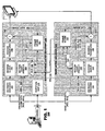
- FIG. 1 is a simplified block diagram of a layered video decoder 100 according to an embodiment of the present invention.
- the video decoder 100 may include a base layer decoder 120 and an enhancement layer decoder 150, each of which receives coded video data received from a channel 180.
- a channel 180 provides physical transport for coded video data; typically, channels are storage media such as electrical, magnetic or optical memory devices or physical transport media such as wired communication links (optical or electrical cables).
- the channel data includes identifiers in the coded signal that distinguish coded data that are intended for decode by the base layer decoder 120 from coded data intended for decode by the enhancement layer decoder 150.
- a base layer decoder 120 may include an entropy decoder 122, an inverse quantizer 124, an inverse transform unit 126, a motion compensation prediction unit 128, an adder 130 and a frame store 132.
- Coded video data often represents video information as a serial data stream which has been entropy coded by, for example, run-length coding.
- the entropy decoder 122 may invert this coding process and build pixelblock arrays of coefficient data for further processing by the base layer decoder 120.
- the inverse quantizer 124 typically multiplies the coefficient data by a quantization parameter to invert a quantization process that had been performed by an encoder (not shown).
- the decoder 120 receives the quantizer parameter either expressly from channel data or by derivation from data provided in the channel; such processes are well known.
- the inverse transform 126 may transform pixelblock coefficients to pixel values according to a transform such as discrete cosine transformation, wavelet coding or other known transform.
- the pixel data generated by the inverse transform unit 126 are output to a first input of the adder 130.
- the frame store 132 may store pixel data of pixelblocks that have been previously decoded by the base layer decoder 120.
- the pixel data may belong to pixelblocks of a video frame currently being decoded.
- pixel data belonging to pixelblocks of previously decoded frames (often called "reference frames") may be available to predict video data of newly received pixelblocks.
- the channel data includes motion vectors 134 for newly received pixelblocks, which identify pixel data from the reference frames that are to be used as prediction sources for the new pixelblocks.
- motion vectors 134 may be provided directly in the channel or may be derived from motion vectors of other pixelblocks in a video sequence.
- a motion compensated predictor 128 may review motion vector data and may cause data to be read from the frame store 132 as sources of prediction for a corresponding pixelblock.
- pixel data may be read from one or two reference frames. Pixel data read from a single reference frame often is presented directly to the adder (line 136). Pixel data read from a pair of reference frames may be processed (for example, averaged) before being presented to the adder 130.
- the adder 130 may generate recovered image data 138 on a pixelblock-by-pixelblock basis, which may be output from the base layer decoder 120 as output data.
- the recovered image data 138 may be stored in the frame store 132 for use in subsequent decoding operations. Recovered image data 138 from the base layer decoder may be output to a display or stored for later use as desired.
- an enhancement layer decoder 150 also may include an entropy decoder 152, an inverse quantizer 154, an inverse transform unit 156, a motion prediction unit 158, an adder 160 and a frame store 162.
- the entropy decoder 152 may invert an entropy coding process used for coded enhancement layer data received from the channel and may build pixelblock arrays of coefficient data for further processing.
- the inverse quantizer 154 may multiply the coefficient data by a quantization parameter to invert a quantization process that had been performed on enhancement layer data by the encoder (not shown).
- the enhancement layer decoder 150 receives a quantizer parameter either expressly from enhancement layer channel data or by derivation from data provided in the channel; such processes are well known.
- the inverse transform 156 may transform pixelblock coefficients to pixel values according to a transform such as discrete cosine transformation, wavelet coding or other known transform.
- the pixel data generated by the inverse transform unit 156 are output to a first input of the adder 160.
- the frame store 162 may store pixel data 164 of pixelblocks that have been previously decoded by the enhancement layer decoder 150.
- the pixel data 164 may belong to pixelblocks of a video frame currently being decoded. Additionally, pixel data belonging to pixelblocks of reference frames previously decoded by the enhancement layer decoder 150 to be available to predict video data of newly received pixelblocks.
- motion vectors for the enhancement layer decoder 150 may be predicted from motion vectors used for the base layer decoder 120.
- the enhancement layer decoder receives motion vector residuals 166 (shown as " ⁇ mv") which help to refine the motion vector prediction.
- the motion compensation predictor 158 receives motion vectors 134 from the base layer channel data and ⁇ mvs 166 from the enhancement layer channel data.
- a partition mapping unit 168 may receive pixelblock definitions for both base layer and enhancement layer decode processes. Each of the decode layers may have had different pixelblock partitioning applied to the coded video.
- the motion compensation predictor 158 may predict motion vectors for enhancement layer pixelblocks as a derivation of the two pixelblock partitioning processes as discussed herein.
- the motion compensated predictor 158 may predict video data from base layer reference frames stored in frame store 132 and/or from enhancement layer reference frames stored in frame store 162 as dictated by decoding instructions provided in the channel 180 via a multiplexer 170 and control lines 172. Recovered image data from the enhancement layer decoder may be output to a display or stored for later use as desired.
- FIG. 1 illustrates a functional block diagram of a video decoder 100.
- video decoders In practice it is common to provide video decoders as software programs to be run on a computer system or as circuit systems in hardware. The principles of the present invention are applicable to all such uses.
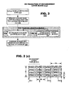
- FIG. 2 illustrates two exemplary pixelblock partitioning schemes applied to a frame of video data.
- coded base layer data represents video data at a certain display size but coded enhancement layer data represents the same video data in a larger size.
- FIG. 2 illustrates an example, in which coded base layer data represents a video frame at a 112x96 pixel size using pixel blocks that are 4x12 pixels ( FIG. 2(a) ).
- coded enhancement layer data represents the same video at a 448x384 pixel size, using pixelblocks that are 64x64 pixels ( FIG. 2(b) ).
- the recovered video is four times the size of the video recovered when only the coded base layer data is decoded.
- Coded video data from the channel 170 may include administrative data that defines the sizes of pixelblocks for both the base layer and the enhancement layer. Such data may be read by the partition mapping unit 168 for use by the motion compensation unit 158 of the enhancement layer ( FIG. 1 ).
- FIG. 3 illustrates a method 300 for predicting motion vectors for use in an enhancement layer decoding process according to an embodiment of the present invention.
- the method 300 may begin by scaling base layer pixelblocks and their motion vectors (step 310).
- the method 300 may identify scaled base layer pixelblocks that are co-located with the respective enhancement layer pixelblock (step 320). Multiple scaled base layer pixelblocks may be identified from this process.
- the method 300 may average the scaled motion vectors corresponding to the scaled pixelblocks in a manner that is weighted according to a degree of overlap between the enhancement layer pixelblock and the scaled base layer pixelblock (step 330).
- a motion vector may be interpolated from motion vectors of neighboring base layer pixelblocks (step 350).
- FIG. 2(c) illustrates operation of the method of FIG. 3 in context of the exemplary base layer and enhancement layer pixelblock partitions of FIG. 2 .
- the recovered enhancement layer video is four times the size of the recovered base layer video.
- Base layer pixelblocks are 4 pixels by 12 pixels and enhancement layer pixelblocks are 64 pixels by 64 pixels. When scaled by difference in video sizes, the scaled base layer pixelblocks are 16 pixels by 48 pixels.
- FIG. 2(c) illustrates three 64x64 enhancement layer pixelblocks 210.1-210.3 (shown in dashed lines) and an array of twelve base layer pixelblocks BPBIk(0,0)-BPBIk(3,3) that have been scaled according to the size difference between the two layers (4x).
- scaled base layer pixelblocks BPBIk(0,0), BPBIk(0,1), BPBIk(0,2) and BPBIk(0,3) are contained entirely within the enhancement layer pixelblock 210.1 but each scaled base layer pixelblocks BPBIk(1,0), BPBIk(1,1), BPBIk(1,2) and BPBIk(1,3) overlap the enhancement layer pixelblock 210.1 by only a third of its area.
- the scaled motion vectors from base layer pixel blocks BPBIk(1,0), BPBIk(1,1), BPBIk(1,2) and BPBIk(1,3) may be given less weight than those of base layer pixelblocks BPBIk(0,0), BPBIk(0,1), BPBIk(0,2) and BPBIk(0,3).
- Base layer pixelblocks BPBIk(1,0), BPBIk(1,1), BPBIk(1,2), BPBIk(1,3), BPBIk(2,0), BPBIk(2,1), BPBIk(2,2) and BPBIk(2,3) each overlap enhancement layer pixelblock 210.2 by two-thirds.
- the motion vectors may be assigned weights corresponding to the degree of overlap. In this example, the weights of all co-located base layer pixelblocks are the same merely because the degree of overlap happens to be the same -- two-thirds.
- embodiments of the present invention provide a method of predicting enhancement layer motion vectors for a multi-layer video decoder in which a base layer video data and an enhancement layer video data are subject to arbitrary pixelblock partitioning before coding.
- a multi-layer decoder may provide for composite image generation and filtering as decoded image data is exchanged between decoding layers.
- the inventors foresee application to coding environments in which enhancement layer decoding is to be performed in a specified area of a video frame, called a "prediction region" herein.
- Inter-layer filtering may be performed on recovered image data corresponding to the prediction region that is obtained from a base layer decoder. If a multipixel filtering operation is to be applied to the recovered base layer data, the filtering operation may not be fully effective at a border of the prediction region.
- prediction region data may be supplemented with border data taken from a previously decoded frame available in a frame store of an enhancement layer decoder.
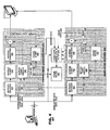
- FIG. 4 is a simplified block diagram of a layer video decoder 400 according to an embodiment of the present invention.
- the video decoder 400 may include a base layer decoder 420 and an enhancement layer decoder 450, each of which receives coded video data received from a channel 480.
- a channel 480 provides physical transport for coded video data; typically, channels are storage media such as electrical, magnetic or optical memory devices or physical transport media such as wired communication links (optical or electrical cables).
- the channel data includes identifiers in the coded signal that distinguish coded data that are intended for decode by the base layer decoder 420 from coded data intended for decode by the enhancement layer decoder 450.
- the channel data includes identifiers that permits a receiving decoder 400 to route data to appropriate enhancement layer decoders.
- a base layer decoder may include an entropy decoder 422, an inverse quantizer 424, an inverse transform unit 426, a motion prediction unit 428, an adder 430 and a frame store 432.
- Coded video data often represent video information as a serial data stream which has been compressed according to an entropy coding scheme such as run-length coding.
- the entropy decoder 422 may invert this coding process and build pixelblock arrays of coefficient data for further processing by the base layer decoder 420.
- the inverse quantizer 424 typically multiplies the coefficient data by a quantization parameter to invert a quantization process that had been performed by an encoder (not shown).
- the decoder receives the quantizer parameter either expressly from channel data or by derivation from data provided in the channel; such processes are well known.
- the inverse transform 426 transforms pixelblock coefficients to pixel values according to a transform such as discrete cosine transformation, wavelet coding or other known transform.
- the pixel data generated by the inverse transform unit 426 are output to a first input of the adder 430.
- the frame store 432 may store pixel data of pixelblocks that have been previously decoded by the base layer decoder 420.
- the pixel data may belong to pixelblocks of a video frame currently being decoded. Additionally, pixel data belonging to pixelblocks reference frames may be available to predict video data of newly received pixelblocks.
- the channel data includes motion vectors 434 for newly received pixelblocks, which identify pixel data to be used as prediction sources for newly received coded pixelblocks. For a given pixelblock, motion vectors 434 may be provided directly in the channel or may be derived from motion vectors of other pixelblocks in a video sequence.
- a motion compensated predictor 428 may review motion vector data and may cause data to be read from the frame store 432 as sources of prediction for a corresponding pixelblock.
- pixel data may be read from one or two reference frames. Pixel data read from a single reference frame often is presented directly to the adder (line 436). Pixel data read from a pair of reference frames may be processed (for example, averaged) before being presented to the adder.
- the adder 430 may generate recovered image data 438 on a block-by-block basis, which may be output from the base layer decoder as output data. If a video frame is identified as a reference frame in a video sequence, the recovered video data may be stored in the frame store 432 for use in subsequent decoding operations. Recovered image data from the base layer decoder 420 may be output to a display or stored for later use as desired.
- the video decoder 400 may include composite image generator and filtering ("CIG") unit 440 and a frame store 442.
- the CIG unit 440 may receive recovered base layer video data 438 in a prediction region. It also may receive decoded image data from an enhancement layer decoder 450.
- the CIG unit 440 may generate composite image data as a merger between prediction region data and recovered enhancement layer data that occurs at a spatial region bordering the prediction region, having been scaled as necessary to overcome image sizing differences between recovered base layer data and recovered enhancement layer data, shown in FIGS. 5 and 6.
- the prediction region data and border region data are from different frames of a video sequence.
- an enhancement layer decoder 450 also may include an entropy decoder 452, an inverse quantizer 454, an inverse transform unit 456, a motion prediction unit 458, an adder 460 and a frame store 462.
- the entropy decoder 452 may invert an entropy coding process used for enhancement layer data received from the channel and may build pixelblock arrays of coefficient data for further processing.
- the inverse quantizer 454 may multiply the coefficient data by a quantization parameter to invert a quantization process that had been performed on enhancement layer data by the encoder (not shown).
- the enhancement layer decoder 450 receives a quantizer parameter either expressly from enhancement layer channel data or by derivation from data provided in the channel; such processes are well known.
- the inverse transform 456 transforms pixelblock coefficients to pixel values according to a transform such as discrete cosine transformation, wavelet coding or other known transform.
- the pixel data generated by the inverse transform unit 456 are output to a first input of the adder 460.
- the frame store 462 may store pixel data 464 of pixelblocks that have been previously decoded by the base layer decoder 450.
- the pixel data 464 may belong to pixelblocks of a video frame currently being decoded. Additionally, pixel data belonging to pixelblocks of reference frames previously decoded by the enhancement layer decoder 450 to be available to predict video data of newly received pixelblocks.
- motion vectors for the enhancement layer decoder 450 may be predicted from motion vectors used for the base layer decoder 420.
- the enhancement layer decoder receives motion vector residuals 466 (shown as " ⁇ mv") which help to refine the motion vector prediction.
- the motion compensation predictor 458 receives motion vectors 434 from the base layer channel data and ⁇ mvs 466 from the enhancement layer channel data.
- the motion compensated predictor 458 may predict video data from prediction data in frame store 442 and/or from enhancement layer reference frames stored in frame store 462 as dictated by decoding instructions provided in the channel 480 via a multiplexer 468 and control lines.
- motion vector prediction may occur according to the processes shown in FIGS. 1-3 .
- Recovered image data from the enhancement layer decoder may be output to a display or stored for later use as desired.
- FIG. 5 illustrates operation of the composite image generation and filtering process of the multi-layer decoder.
- FIG. 5 (a) shows operation of the base layer decoder 520 which generates recovered base layer image data 522 from channel data (not shown).
- the base layer image data 522 is confined to a prediction region, shown in FIG. 5 (b) .
- the enhancement layer decoder 550 stores image data for previously-decoded frames (in frame store 552) from which border region data may be extracted ( FIG. 5 (b) ).
- border region data is shown having been scaled to synchronize its image size with that of the border region.
- the CIG unit 530 includes an image merge unit 532 that develops a composite image from the prediction region data and the image data available in the enhancement layer frame store 552. Specifically, having determined which filtering operation is to be performed, the image merge unit 532 may determine how much border region data must be obtained to perform the filtering operation fully on each pixel location within the prediction region. The image merge unit 532 may retrieve a corresponding amount of data from the frame store 532 and integrate it with the prediction region image data 522. Thereafter, filtering 534 may be applied to the composite image data in a traditional manner. The filtered image data may be stored in frame store 540 to be available to the enhancement layer decoder 550 in subsequent decoding operations.
- the inter-layer composite image generation and filtering process may find application with a variety of well-known filtering operations, including for example deblocking filters, ringing filters, edge detection filters and the like.
- the type of filtering operation may be specified to the composite image generator and filtering unit 530 via an administrative signal 536 provided in the channel or derived therefrom (also shown as a mode signals 444 in FIG. 4 ).
- the merger and filtering operations may be performed on data obtained at stages of decoding that are earlier than the recovered data output by the respective decoders 420, 450.
- the CIG unit 440 shows inputs (in phantom) taken from the inverse transform unit 426, the inverse quantizer 424 and the entropy decoder 422 as alternatives to line 438.
- the CIG unit 440 may take similar data from the enhancement layer decoder (not shown in FIG. 4 ). In such cases, the CIG unit 440 may include filtering units ( FIG. 5 , 530) that are specific to the types of data taken from the respective decoders 420, 450.
Landscapes
- Engineering & Computer Science (AREA)
- Multimedia (AREA)
- Signal Processing (AREA)
- Compression Or Coding Systems Of Tv Signals (AREA)
Description
- The present invention relates to video decoders and, more specifically, to an improved multi-layer video decoder.
- Video coding refers generally to coding motion picture information to transmission over a bandwidth limited channel. Various video coding techniques are known. The most common techniques, such as those are standardized in the ITU H-series and MPEG-series coding specifications, employ motion compensation prediction to reduce channel bandwidth. Motion compensated video coders exploit temporal redundancy between frames of a video sequence by predicting video content of a new frame currently being decoded with reference to video content of other frames that were previously decoded. At a decoder, having received and decoded a first number of frames, the video decoder is able to use decoded video content of the previously decoded frames to generate content of other frames.
- Layered video coding systems structure video coding/decoding operations and coded video data for a wide variety of applications. Coded video data may include a first set of video data, called "base layer" data herein, from which the source video data can be recovered at a first level of image quality. The coded video data may include other sets of video data, called "enhancement layer" data herein, from which when decoded in conjunction with the base layer data the source video data can be recovered at a higher level of image quality that can be achieved when decoding the base layer data alone.
- Layered video coding system find application in a host of coding environments. For example, layered coding systems can be advantageous when coding video data for a variety of different video decoders, some of which may have relatively modest processing resources but others that have far greater processing resources. A simple decoder may recover a basic representation of the source video by decoding and displaying only the base layer data. A more robust decoder, however, may recover better image quality by decoding not only the base layer data but also data from one or more enhancement layers. In other applications, a layered coding scheme may be advantageous in transmission environments where channel bandwidth cannot be determined in advance. If limited channel bandwidth is available, a transmitter of coded data may send only the base layer data through the channel, which permits a video decoder to display at least a basic representation of the source video. A transmitter may send multiple layers of coded data through a larger channel, which will yield better image quality.
US 2006/012719 describes a system and method for motion prediction in scaleable video coding, by obtaining current layer motion vectors; determining a final base layer motion vector; and calculating a predictive motion vector based on the current layer motion vectors and the final base layer motion vector. A similarity or consistency of neighbouring motion vectors at a current layer and a reliability of motion vector prediction using neighbouring motion vectors at a base layer may be used to determine the predictive motion vector. - The inventors of the present application propose several coding improvements to a multilayer video coding system as described herein.
-
FIG. 1 is a simplified block diagram of a multi-layer video decoder according to an embodiment of the present invention. -
FIG. 2 illustrates pixelblock partitioning for base layer coding and enhancement layer coding according to an embodiment of the present invention. -
FIG. 3 illustrates a method of predicting motion vectors for an enhancement layer video decoder according to an embodiment of the present invention. -
FIG. 4 is a simplified block diagram of a multi-layer video decoder according to another embodiment of the present invention. -
FIG. 5 is a flow diagram of a multi-layer video decoder. - A first improvement is obtained for prediction of motion vectors to be used in prediction of video data for enhancement layer data. Arbitrary pixelblock partitioning between base layer data and enhancement layer data raises problems to identify base layer motion vectors to be used as prediction sources for enhancement layer motion vectors. The inventors propose to develop motion vectors by scaling a base layer pixelblock partitioning map according to a size difference between the base layer video image and the enhancement layer video image, then identifying from the scaled map scaled base layer pixelblocks that are co-located with the enhancement layer pixelblocks for which motion vector prediction is to be performed. Motion vectors from the scaled co-located base layer pixelblocks are averaged in a weighted manner according to a degree of overlap between the scaled base layer pixelblocks and the enhancement layer pixelblock. Another improvement is obtained by filtering recovered base layer image data before it is provided to an enhancement layer decoder. When a specified filter requires image data outside a prediction region available from a base layer decoder, the prediction region data may be supplemented with previously-decoded data from an enhancement layer at a border of the prediction region. Filtering may be performed on a composite image obtained by the merger of the prediction region image data and the border region image data.
-
FIG. 1 is a simplified block diagram of alayered video decoder 100 according to an embodiment of the present invention. As illustrated, thevideo decoder 100 may include abase layer decoder 120 and anenhancement layer decoder 150, each of which receives coded video data received from achannel 180. Achannel 180 provides physical transport for coded video data; typically, channels are storage media such as electrical, magnetic or optical memory devices or physical transport media such as wired communication links (optical or electrical cables). The channel data includes identifiers in the coded signal that distinguish coded data that are intended for decode by thebase layer decoder 120 from coded data intended for decode by theenhancement layer decoder 150. In certain implementations, it may be advantageous to provide multiple enhancement layer decoders (only one is shown inFIG. 1 ) and, in such case, the channel data includes identifiers that permits areceiving decoder 100 to route data to appropriate enhancement layer decoders. - As illustrated in
FIG. 1 , abase layer decoder 120 may include anentropy decoder 122, aninverse quantizer 124, aninverse transform unit 126, a motioncompensation prediction unit 128, anadder 130 and aframe store 132. Coded video data often represents video information as a serial data stream which has been entropy coded by, for example, run-length coding. Theentropy decoder 122 may invert this coding process and build pixelblock arrays of coefficient data for further processing by thebase layer decoder 120. Theinverse quantizer 124 typically multiplies the coefficient data by a quantization parameter to invert a quantization process that had been performed by an encoder (not shown). Thedecoder 120 receives the quantizer parameter either expressly from channel data or by derivation from data provided in the channel; such processes are well known. Theinverse transform 126 may transform pixelblock coefficients to pixel values according to a transform such as discrete cosine transformation, wavelet coding or other known transform. The pixel data generated by theinverse transform unit 126 are output to a first input of theadder 130. - Modern video coders often use predictive coding techniques to reduce bandwidth of coded signals. The
frame store 132 may store pixel data of pixelblocks that have been previously decoded by thebase layer decoder 120. The pixel data may belong to pixelblocks of a video frame currently being decoded. Additionally, pixel data belonging to pixelblocks of previously decoded frames (often called "reference frames") may be available to predict video data of newly received pixelblocks. In such cases, the channel data includesmotion vectors 134 for newly received pixelblocks, which identify pixel data from the reference frames that are to be used as prediction sources for the new pixelblocks. For a given pixelblock,motion vectors 134 may be provided directly in the channel or may be derived from motion vectors of other pixelblocks in a video sequence. - A motion compensated
predictor 128 may review motion vector data and may cause data to be read from theframe store 132 as sources of prediction for a corresponding pixelblock. Depending on a mode of prediction used, pixel data may be read from one or two reference frames. Pixel data read from a single reference frame often is presented directly to the adder (line 136). Pixel data read from a pair of reference frames may be processed (for example, averaged) before being presented to theadder 130. Theadder 130 may generate recoveredimage data 138 on a pixelblock-by-pixelblock basis, which may be output from thebase layer decoder 120 as output data. If a video frame is identified as a reference frame in a video sequence, the recoveredimage data 138 may be stored in theframe store 132 for use in subsequent decoding operations. Recoveredimage data 138 from the base layer decoder may be output to a display or stored for later use as desired. - As illustrated in
FIG. 1 , anenhancement layer decoder 150 also may include anentropy decoder 152, aninverse quantizer 154, aninverse transform unit 156, amotion prediction unit 158, an adder 160 and aframe store 162. Theentropy decoder 152 may invert an entropy coding process used for coded enhancement layer data received from the channel and may build pixelblock arrays of coefficient data for further processing. Theinverse quantizer 154 may multiply the coefficient data by a quantization parameter to invert a quantization process that had been performed on enhancement layer data by the encoder (not shown). Theenhancement layer decoder 150 receives a quantizer parameter either expressly from enhancement layer channel data or by derivation from data provided in the channel; such processes are well known. Theinverse transform 156 may transform pixelblock coefficients to pixel values according to a transform such as discrete cosine transformation, wavelet coding or other known transform. The pixel data generated by theinverse transform unit 156 are output to a first input of the adder 160. - The
frame store 162 may storepixel data 164 of pixelblocks that have been previously decoded by theenhancement layer decoder 150. Thepixel data 164 may belong to pixelblocks of a video frame currently being decoded. Additionally, pixel data belonging to pixelblocks of reference frames previously decoded by theenhancement layer decoder 150 to be available to predict video data of newly received pixelblocks. According to an embodiment of the present invention, motion vectors for theenhancement layer decoder 150 may be predicted from motion vectors used for thebase layer decoder 120. The enhancement layer decoder receives motion vector residuals 166 (shown as "Δmv") which help to refine the motion vector prediction. - In an embodiment, the
motion compensation predictor 158 receivesmotion vectors 134 from the base layer channel data andΔmvs 166 from the enhancement layer channel data. Apartition mapping unit 168 may receive pixelblock definitions for both base layer and enhancement layer decode processes. Each of the decode layers may have had different pixelblock partitioning applied to the coded video. Themotion compensation predictor 158 may predict motion vectors for enhancement layer pixelblocks as a derivation of the two pixelblock partitioning processes as discussed herein. The motion compensatedpredictor 158 may predict video data from base layer reference frames stored inframe store 132 and/or from enhancement layer reference frames stored inframe store 162 as dictated by decoding instructions provided in thechannel 180 via amultiplexer 170 andcontrol lines 172. Recovered image data from the enhancement layer decoder may be output to a display or stored for later use as desired. -
FIG. 1 illustrates a functional block diagram of avideo decoder 100. In practice it is common to provide video decoders as software programs to be run on a computer system or as circuit systems in hardware. The principles of the present invention are applicable to all such uses. -
FIG. 2 illustrates two exemplary pixelblock partitioning schemes applied to a frame of video data. In one common application, coded base layer data represents video data at a certain display size but coded enhancement layer data represents the same video data in a larger size.FIG. 2 illustrates an example, in which coded base layer data represents a video frame at a 112x96 pixel size using pixel blocks that are 4x12 pixels (FIG. 2(a) ). In the example, coded enhancement layer data represents the same video at a 448x384 pixel size, using pixelblocks that are 64x64 pixels (FIG. 2(b) ). Thus, when the coded enhancement layer is decoded, the recovered video is four times the size of the video recovered when only the coded base layer data is decoded. - Coded video data from the
channel 170 may include administrative data that defines the sizes of pixelblocks for both the base layer and the enhancement layer. Such data may be read by thepartition mapping unit 168 for use by themotion compensation unit 158 of the enhancement layer (FIG. 1 ). -
FIG. 3 illustrates amethod 300 for predicting motion vectors for use in an enhancement layer decoding process according to an embodiment of the present invention. Themethod 300 may begin by scaling base layer pixelblocks and their motion vectors (step 310). To predict a motion vector of an enhancement layer pixelblock, themethod 300 may identify scaled base layer pixelblocks that are co-located with the respective enhancement layer pixelblock (step 320). Multiple scaled base layer pixelblocks may be identified from this process. For each such scaled base layer pixelblock, themethod 300 may average the scaled motion vectors corresponding to the scaled pixelblocks in a manner that is weighted according to a degree of overlap between the enhancement layer pixelblock and the scaled base layer pixelblock (step 330). In an embodiment, if a scaled base layer pixelblock does not have a motion vector associated therewith (step 340), a motion vector may be interpolated from motion vectors of neighboring base layer pixelblocks (step 350). -
FIG. 2(c) illustrates operation of the method ofFIG. 3 in context of the exemplary base layer and enhancement layer pixelblock partitions ofFIG. 2 . As noted, the recovered enhancement layer video is four times the size of the recovered base layer video. Base layer pixelblocks are 4 pixels by 12 pixels and enhancement layer pixelblocks are 64 pixels by 64 pixels. When scaled by difference in video sizes, the scaled base layer pixelblocks are 16 pixels by 48 pixels.FIG. 2(c) illustrates three 64x64 enhancement layer pixelblocks 210.1-210.3 (shown in dashed lines) and an array of twelve base layer pixelblocks BPBIk(0,0)-BPBIk(3,3) that have been scaled according to the size difference between the two layers (4x). As illustrated, boundaries between scaled base layer pixelblocks to not aligned to boundaries between enhancement layer pixelblocks. For example, scaled base layer pixelblocks BPBIk(0,0), BPBIk(0,1), BPBIk(0,2) and BPBIk(0,3) are contained entirely within the enhancement layer pixelblock 210.1 but each scaled base layer pixelblocks BPBIk(1,0), BPBIk(1,1), BPBIk(1,2) and BPBIk(1,3) overlap the enhancement layer pixelblock 210.1 by only a third of its area. When averaging the contribution of the motion vectors of these base layer pixelblocks, the scaled motion vectors from base layer pixel blocks BPBIk(1,0), BPBIk(1,1), BPBIk(1,2) and BPBIk(1,3) may be given less weight than those of base layer pixelblocks BPBIk(0,0), BPBIk(0,1), BPBIk(0,2) and BPBIk(0,3). - With respect to enhancement layer pixel block 210.2, no scaled base layer pixelblock falls entirely within its area. Base layer pixelblocks BPBIk(1,0), BPBIk(1,1), BPBIk(1,2), BPBIk(1,3), BPBIk(2,0), BPBIk(2,1), BPBIk(2,2) and BPBIk(2,3) each overlap enhancement layer pixelblock 210.2 by two-thirds. When averaging contribution of the motion vectors for each of the base layer pixelblocks, the motion vectors may be assigned weights corresponding to the degree of overlap. In this example, the weights of all co-located base layer pixelblocks are the same merely because the degree of overlap happens to be the same -- two-thirds.
- As shown above, embodiments of the present invention provide a method of predicting enhancement layer motion vectors for a multi-layer video decoder in which a base layer video data and an enhancement layer video data are subject to arbitrary pixelblock partitioning before coding.
- According to another embodiment of the present invention, a multi-layer decoder may provide for composite image generation and filtering as decoded image data is exchanged between decoding layers. The inventors foresee application to coding environments in which enhancement layer decoding is to be performed in a specified area of a video frame, called a "prediction region" herein. Inter-layer filtering may be performed on recovered image data corresponding to the prediction region that is obtained from a base layer decoder. If a multipixel filtering operation is to be applied to the recovered base layer data, the filtering operation may not be fully effective at a border of the prediction region. To improve performance of the filtering operation, prediction region data may be supplemented with border data taken from a previously decoded frame available in a frame store of an enhancement layer decoder.
-
FIG. 4 is a simplified block diagram of alayer video decoder 400 according to an embodiment of the present invention. As illustrated, thevideo decoder 400 may include abase layer decoder 420 and anenhancement layer decoder 450, each of which receives coded video data received from achannel 480. Achannel 480 provides physical transport for coded video data; typically, channels are storage media such as electrical, magnetic or optical memory devices or physical transport media such as wired communication links (optical or electrical cables). The channel data includes identifiers in the coded signal that distinguish coded data that are intended for decode by thebase layer decoder 420 from coded data intended for decode by theenhancement layer decoder 450. In certain implementations, it may be advantageous to provide multiple enhancement layer decoders (only one is shown inFIG. 4 ) and, in such case, the channel data includes identifiers that permits a receivingdecoder 400 to route data to appropriate enhancement layer decoders. - As illustrated in
FIG. 4 , a base layer decoder may include anentropy decoder 422, aninverse quantizer 424, aninverse transform unit 426, amotion prediction unit 428, anadder 430 and aframe store 432. Coded video data often represent video information as a serial data stream which has been compressed according to an entropy coding scheme such as run-length coding. Theentropy decoder 422 may invert this coding process and build pixelblock arrays of coefficient data for further processing by thebase layer decoder 420. Theinverse quantizer 424 typically multiplies the coefficient data by a quantization parameter to invert a quantization process that had been performed by an encoder (not shown). The decoder receives the quantizer parameter either expressly from channel data or by derivation from data provided in the channel; such processes are well known. Theinverse transform 426 transforms pixelblock coefficients to pixel values according to a transform such as discrete cosine transformation, wavelet coding or other known transform. The pixel data generated by theinverse transform unit 426 are output to a first input of theadder 430. - The
frame store 432 may store pixel data of pixelblocks that have been previously decoded by thebase layer decoder 420. The pixel data may belong to pixelblocks of a video frame currently being decoded. Additionally, pixel data belonging to pixelblocks reference frames may be available to predict video data of newly received pixelblocks. In such cases, the channel data includesmotion vectors 434 for newly received pixelblocks, which identify pixel data to be used as prediction sources for newly received coded pixelblocks. For a given pixelblock,motion vectors 434 may be provided directly in the channel or may be derived from motion vectors of other pixelblocks in a video sequence. - A motion compensated
predictor 428 may review motion vector data and may cause data to be read from theframe store 432 as sources of prediction for a corresponding pixelblock. Depending on a mode of prediction used, pixel data may be read from one or two reference frames. Pixel data read from a single reference frame often is presented directly to the adder (line 436). Pixel data read from a pair of reference frames may be processed (for example, averaged) before being presented to the adder. Theadder 430 may generate recoveredimage data 438 on a block-by-block basis, which may be output from the base layer decoder as output data. If a video frame is identified as a reference frame in a video sequence, the recovered video data may be stored in theframe store 432 for use in subsequent decoding operations. Recovered image data from thebase layer decoder 420 may be output to a display or stored for later use as desired. - According to an embodiment, the
video decoder 400 may include composite image generator and filtering ("CIG")unit 440 and aframe store 442. TheCIG unit 440 may receive recovered baselayer video data 438 in a prediction region. It also may receive decoded image data from anenhancement layer decoder 450. TheCIG unit 440 may generate composite image data as a merger between prediction region data and recovered enhancement layer data that occurs at a spatial region bordering the prediction region, having been scaled as necessary to overcome image sizing differences between recovered base layer data and recovered enhancement layer data, shown inFIGS. 5 and 6. The prediction region data and border region data are from different frames of a video sequence. - As illustrated in
FIG. 4 , anenhancement layer decoder 450 also may include anentropy decoder 452, aninverse quantizer 454, aninverse transform unit 456, amotion prediction unit 458, anadder 460 and aframe store 462. Theentropy decoder 452 may invert an entropy coding process used for enhancement layer data received from the channel and may build pixelblock arrays of coefficient data for further processing. Theinverse quantizer 454 may multiply the coefficient data by a quantization parameter to invert a quantization process that had been performed on enhancement layer data by the encoder (not shown). Theenhancement layer decoder 450 receives a quantizer parameter either expressly from enhancement layer channel data or by derivation from data provided in the channel; such processes are well known. Theinverse transform 456 transforms pixelblock coefficients to pixel values according to a transform such as discrete cosine transformation, wavelet coding or other known transform. The pixel data generated by theinverse transform unit 456 are output to a first input of theadder 460. - The
frame store 462 may store pixel data 464 of pixelblocks that have been previously decoded by thebase layer decoder 450. The pixel data 464 may belong to pixelblocks of a video frame currently being decoded. Additionally, pixel data belonging to pixelblocks of reference frames previously decoded by theenhancement layer decoder 450 to be available to predict video data of newly received pixelblocks. According to an embodiment of the present invention, motion vectors for theenhancement layer decoder 450 may be predicted from motion vectors used for thebase layer decoder 420. The enhancement layer decoder receives motion vector residuals 466 (shown as "Δmv") which help to refine the motion vector prediction. - In an embodiment, the
motion compensation predictor 458 receivesmotion vectors 434 from the base layer channel data andΔmvs 466 from the enhancement layer channel data. The motion compensatedpredictor 458 may predict video data from prediction data inframe store 442 and/or from enhancement layer reference frames stored inframe store 462 as dictated by decoding instructions provided in thechannel 480 via amultiplexer 468 and control lines. Optionally, motion vector prediction may occur according to the processes shown inFIGS. 1-3 . Recovered image data from the enhancement layer decoder may be output to a display or stored for later use as desired. -
FIG. 5 illustrates operation of the composite image generation and filtering process of the multi-layer decoder.FIG. 5 (a) shows operation of thebase layer decoder 520 which generates recovered baselayer image data 522 from channel data (not shown). The baselayer image data 522 is confined to a prediction region, shown inFIG. 5 (b) . Theenhancement layer decoder 550 stores image data for previously-decoded frames (in frame store 552) from which border region data may be extracted (FIG. 5 (b) ). InFIG. 5 (b) , prediction region data is shown having been scaled to synchronize its image size with that of the border region. - The
CIG unit 530 includes animage merge unit 532 that develops a composite image from the prediction region data and the image data available in the enhancementlayer frame store 552. Specifically, having determined which filtering operation is to be performed, theimage merge unit 532 may determine how much border region data must be obtained to perform the filtering operation fully on each pixel location within the prediction region. Theimage merge unit 532 may retrieve a corresponding amount of data from theframe store 532 and integrate it with the predictionregion image data 522. Thereafter, filtering 534 may be applied to the composite image data in a traditional manner. The filtered image data may be stored inframe store 540 to be available to theenhancement layer decoder 550 in subsequent decoding operations. - The inter-layer composite image generation and filtering process may find application with a variety of well-known filtering operations, including for example deblocking filters, ringing filters, edge detection filters and the like. The type of filtering operation may be specified to the composite image generator and
filtering unit 530 via anadministrative signal 536 provided in the channel or derived therefrom (also shown as a mode signals 444 inFIG. 4 ). - In an embodiment, the merger and filtering operations may be performed on data obtained at stages of decoding that are earlier than the recovered data output by the
respective decoders CIG unit 440 shows inputs (in phantom) taken from theinverse transform unit 426, theinverse quantizer 424 and theentropy decoder 422 as alternatives toline 438. TheCIG unit 440 may take similar data from the enhancement layer decoder (not shown inFIG. 4 ). In such cases, theCIG unit 440 may include filtering units (FIG. 5 , 530) that are specific to the types of data taken from therespective decoders - Several embodiments of the present invention are specifically illustrated and described herein. However, it will be appreciated that modifications and variations of the present invention are covered by the above teachings and within the purview of the appended claims without departing from the intended scope of the invention.
Claims (14)
- A method of predicting motion vectors in a multi-layer video decoding process, comprising:determining a size difference between recovered video data obtained solely by a base layer decode process and recovered video data obtained from an enhancement layer decode process;scaling a base layer pixelblock partition map according to the determined size difference;predicting a motion vector of an enhancement layer pixelblock according to:determining which base layer pixelblock(s), when scaled according to the size difference, are co-located with the enhancement layer pixelblock,scaling motion vectors of the co-located base layer pixelblock(s) according to the size difference, andaveraging the scaled motion vectors of the co-located base layer pixelblock(s), wherein the averaging weight contribution of each scaled motion vector is based on a degree of overlap between the enhancement layer pixelblock and the respective scaled base layer pixelblock.
- The method of claim 1, further comprising, when a co-located base layer pixelblock does not have a motion vector associated with it, interpolating a motion vector for the respective base layer pixelblock from motion vectors of neighboring base layer pixelblocks.
- The method of claim 1, further comprising developing a partition map from enhancement layer pixelblock definitions and base layer pixelblocks received from a communication channel.
- The method of claim 1, further comprising predicting data of the enhancement layer pixelblock from at least one of stored decoded base layer image data according to the predicted motion vector, and stored decoded enhancement layer image data according to the predicted motion vector.
- A multi-layer video decoder, comprising:a base layer decoder to generate recovered base layer image data from base layer coded video provided in a channel according to temporal prediction techniques, andan enhancement layer decoder to generate recovered enhancement layer image data from enhancement layer coded video provided in a channel according to temporal prediction techniques, comprising:a partition map that stores information representing pixelblock partitioning of the base layer image data and of the enhancement layer image data anda motion compensation predictor that predicts recovered enhancement layer image data from previously decoded image data according to a motion vectors, a motion vector of at least one enhancement layer pixelblock being predicted according to:determining which base layer pixelblock(s), when scaled according to a size difference between base layer pixelblocks and enhancement layer pixelblocks, are co-located with the enhancement layer pixelblock,scaling motion vectors of the co-located base layer pixelblock(s) according to the size difference, andaveraging the scaled motion vectors of the co-located base layer pixelblock(s), wherein the averaging weight contribution of each scaled motion vector is based on a degree of overlap between the enhancement layer pixelblock and the respective scaled base layer pixelblock.
- The decoder of claim 5, wherein, when a co-located base layer pixelblock does not have a motion vector associated with it, the motion compensation predictor interpolates a motion vector for the respective base layer pixelblock from motion vectors of neighboring base layer pixelblocks.
- The decoder of claim 5, wherein the partition map derives the partitioning information from enhancement layer pixelblock definitions and base layer pixelblocks received from a communication channel.
- The decoder of claim 5, wherein the previously decoded image data is at least one of stored decoded base layer image data, and stored decoded enhancement layer image data.
- A video decoding method comprising:decoding recovered prediction region data from base layer coded video provided in a channel according to temporal prediction techniques,generating composite image data as a merger between the recovered prediction region data with border data taken from previously-decoded recovered enhancement layer data,filtering the composite image data, andgenerating new recovered enhancement layer image data from the filtered composite image data and from enhancement layer coded video provided in a channel according to temporal prediction techniques.
- The method of claim 9, wherein an amount of data to be taken as a border region is determined from a type of filtering to be applied.
- The method of claim 9, wherein the filtering is at least one of deblocking filtering, ringing filtering, and edge detection filtering.
- A video decoder, comprising:a base layer decoder to generate recovered base layer image data from base layer coded video provided in a channel according to temporal prediction techniques;an enhancement layer decoder to generate recovered enhancement layer image data from enhancement layer coded video provided in a channel according to temporal prediction techniques, the enhancement layer decoding having storage for reference frames of recovered enhancement layer image data;a composite image generator having inputs for recovered base layer image data and reference frames of recovered enhancement layer image data, the generator to merge prediction region data from the recovered base layer image data with a border region from the reference frames of recovered enhancement layer image data, the prediction region having been scaled to account for any size difference between the recovered base layer data and the recovered enhancement layer image data, wherein the border region is taken from a spatial area that borders a spatial area occupied by the prediction region;a filter that applies image filtering to the merged data, wherein an output of the filter is input to the enhancement layer decoder as reference image data for temporal prediction.
- The decoder of claim 12, wherein a width of the border region is determined from a type of image filtering to be applied.
- The decoder of claim 12, wherein the image filtering is at least one of deblocking filtering, ringing filtering, and edge detection filtering.
Applications Claiming Priority (2)
| Application Number | Priority Date | Filing Date | Title |
|---|---|---|---|
| US85293906P | 2006-10-18 | 2006-10-18 | |
| PCT/US2007/081758 WO2008049052A2 (en) | 2006-10-18 | 2007-10-18 | Scalable video coding with filtering of lower layers |
Publications (2)
| Publication Number | Publication Date |
|---|---|
| EP2077038A2 EP2077038A2 (en) | 2009-07-08 |
| EP2077038B1 true EP2077038B1 (en) | 2013-01-30 |
Family
ID=39201609
Family Applications (1)
| Application Number | Title | Priority Date | Filing Date |
|---|---|---|---|
| EP07844389A Not-in-force EP2077038B1 (en) | 2006-10-18 | 2007-10-18 | Scalable video coding with filtering of lower layers |
Country Status (4)
| Country | Link |
|---|---|
| US (1) | US20080095238A1 (en) |
| EP (1) | EP2077038B1 (en) |
| JP (2) | JP5134001B2 (en) |
| WO (1) | WO2008049052A2 (en) |
Families Citing this family (39)
| Publication number | Priority date | Publication date | Assignee | Title |
|---|---|---|---|---|
| US7456760B2 (en) * | 2006-09-11 | 2008-11-25 | Apple Inc. | Complexity-aware encoding |
| US8548056B2 (en) * | 2007-01-08 | 2013-10-01 | Qualcomm Incorporated | Extended inter-layer coding for spatial scability |
| WO2008091206A1 (en) * | 2007-01-26 | 2008-07-31 | Telefonaktiebolaget Lm Ericsson (Publ) | Motion estimation for uncovered frame regions |
| US20080225952A1 (en) * | 2007-03-15 | 2008-09-18 | Nokia Corporation | System and method for providing improved residual prediction for spatial scalability in video coding |
| US20090207915A1 (en) * | 2008-02-15 | 2009-08-20 | Freescale Semiconductor, Inc. | Scalable motion search ranges in multiple resolution motion estimation for video compression |
| JP4813517B2 (en) * | 2008-05-29 | 2011-11-09 | オリンパス株式会社 | Image processing apparatus, image processing program, image processing method, and electronic apparatus |
| WO2010021666A1 (en) | 2008-08-20 | 2010-02-25 | Thomson Licensing | Refined depth map |
| BRPI0918619A2 (en) * | 2008-09-17 | 2019-09-03 | Sharp Kk | scalable video stream decoder and scalable video stream generator |
| KR20110126103A (en) | 2009-01-07 | 2011-11-22 | 톰슨 라이센싱 | Joint depth estimation |
| JP2012516625A (en) | 2009-01-27 | 2012-07-19 | トムソン ライセンシング | Method and apparatus for selection of transforms in video encoding and video decoding |
| JP2010288110A (en) * | 2009-06-12 | 2010-12-24 | Sony Corp | Image processing apparatus and method |
| US9300969B2 (en) | 2009-09-09 | 2016-03-29 | Apple Inc. | Video storage |
| CN105933715B (en) * | 2010-04-13 | 2019-04-12 | Ge视频压缩有限责任公司 | Across planar prediction |
| KR102360005B1 (en) | 2010-04-13 | 2022-02-08 | 지이 비디오 컴프레션, 엘엘씨 | Sample region merging |
| SI3697089T1 (en) | 2010-04-13 | 2022-01-31 | Ge Video Compression, Llc | Inheritance in sample array multitree subdivision |
| BR122020007921B1 (en) | 2010-04-13 | 2021-08-03 | Ge Video Compression, Llc | INTERPLANE PREDICTION |
| DK3958573T3 (en) | 2010-04-13 | 2023-08-28 | Ge Video Compression Llc | Video Coding Using Multitree Subdivision of Images |
| KR20110114957A (en) * | 2010-04-14 | 2011-10-20 | 삼성전기주식회사 | Data transmission apparatus and method, network data transmission system and method using the same |
| US8976856B2 (en) | 2010-09-30 | 2015-03-10 | Apple Inc. | Optimized deblocking filters |
| JP5830993B2 (en) * | 2011-07-14 | 2015-12-09 | ソニー株式会社 | Image processing apparatus and image processing method |
| US20130188719A1 (en) * | 2012-01-20 | 2013-07-25 | Qualcomm Incorporated | Motion prediction in svc using motion vector for intra-coded block |
| US20130287109A1 (en) * | 2012-04-29 | 2013-10-31 | Qualcomm Incorporated | Inter-layer prediction through texture segmentation for video coding |
| JP6005847B2 (en) * | 2012-06-15 | 2016-10-12 | インテル コーポレイション | Adaptive filtering for scalable video coding |
| US9247242B2 (en) | 2012-07-09 | 2016-01-26 | Qualcomm Incorporated | Skip transform and residual coding mode extension for difference domain intra prediction |
| US9635356B2 (en) * | 2012-08-07 | 2017-04-25 | Qualcomm Incorporated | Multi-hypothesis motion compensation for scalable video coding and 3D video coding |
| US9900593B2 (en) * | 2012-08-29 | 2018-02-20 | Vid Scale, Inc. | Method and apparatus of motion vector prediction for scalable video coding |
| US20140086328A1 (en) * | 2012-09-25 | 2014-03-27 | Qualcomm Incorporated | Scalable video coding in hevc |
| KR102257542B1 (en) * | 2012-10-01 | 2021-05-31 | 지이 비디오 컴프레션, 엘엘씨 | Scalable video coding using subblock-based coding of transform coefficient blocks in the enhancement layer |
| US9693060B2 (en) | 2012-11-16 | 2017-06-27 | Qualcomm Incorporated | Device and method for scalable coding of video information |
| US9648319B2 (en) | 2012-12-12 | 2017-05-09 | Qualcomm Incorporated | Device and method for scalable coding of video information based on high efficiency video coding |
| WO2014097937A1 (en) * | 2012-12-20 | 2014-06-26 | ソニー株式会社 | Image processing device and image processing method |
| US20140192880A1 (en) * | 2013-01-04 | 2014-07-10 | Zhipin Deng | Inter layer motion data inheritance |
| EP3758379A3 (en) * | 2013-04-08 | 2021-02-24 | GE Video Compression, LLC | Coding concept allowing efficient multi-view/layer coding |
| WO2014175658A1 (en) * | 2013-04-24 | 2014-10-30 | 인텔렉추얼 디스커버리 주식회사 | Video encoding and decoding method, and apparatus using same |
| FR3008840A1 (en) * | 2013-07-17 | 2015-01-23 | Thomson Licensing | METHOD AND DEVICE FOR DECODING A SCALABLE TRAIN REPRESENTATIVE OF AN IMAGE SEQUENCE AND CORRESPONDING ENCODING METHOD AND DEVICE |
| CN106063271B (en) * | 2013-12-26 | 2019-09-03 | 三星电子株式会社 | For executing cross-layer video coding/decoding method and its equipment and the cross-layer video coding method and its equipment for executing the prediction based on sub-block of the prediction based on sub-block |
| MX2021002557A (en) * | 2018-09-07 | 2021-04-29 | Panasonic Ip Corp America | System and method for video coding. |
| CN113228102A (en) * | 2019-01-09 | 2021-08-06 | 奥林巴斯株式会社 | Image processing apparatus, image processing method, and image processing program |
| WO2021141372A1 (en) * | 2020-01-06 | 2021-07-15 | 현대자동차주식회사 | Image encoding and decoding based on reference picture having different resolution |
Family Cites Families (53)
| Publication number | Priority date | Publication date | Assignee | Title |
|---|---|---|---|---|
| US4958226A (en) * | 1989-09-27 | 1990-09-18 | At&T Bell Laboratories | Conditional motion compensated interpolation of digital motion video |
| US5465119A (en) * | 1991-02-22 | 1995-11-07 | Demografx | Pixel interlacing apparatus and method |
| US5488418A (en) * | 1991-04-10 | 1996-01-30 | Mitsubishi Denki Kabushiki Kaisha | Encoder and decoder |
| US5467136A (en) * | 1991-05-31 | 1995-11-14 | Kabushiki Kaisha Toshiba | Video decoder for determining a motion vector from a scaled vector and a difference vector |
| US5414469A (en) * | 1991-10-31 | 1995-05-09 | International Business Machines Corporation | Motion video compression system with multiresolution features |
| US5408328A (en) * | 1992-03-23 | 1995-04-18 | Ricoh Corporation, California Research Center | Compressed image virtual editing system |
| JPH05316360A (en) * | 1992-05-14 | 1993-11-26 | Fuji Xerox Co Ltd | Coding/decoding device for picture signal |
| CA2126467A1 (en) * | 1993-07-13 | 1995-01-14 | Barin Geoffry Haskell | Scalable encoding and decoding of high-resolution progressive video |
| KR970003102B1 (en) * | 1993-09-17 | 1997-03-14 | 대우전자 주식회사 | Half pixel motion compensation circuit for video decoder |
| JP3385077B2 (en) * | 1993-10-28 | 2003-03-10 | 松下電器産業株式会社 | Motion vector detection device |
| US5929913A (en) * | 1993-10-28 | 1999-07-27 | Matsushita Electrical Industrial Co., Ltd | Motion vector detector and video coder |
| JP2956464B2 (en) * | 1993-12-29 | 1999-10-04 | 日本ビクター株式会社 | Image information compression / decompression device |
| EP0687112B1 (en) * | 1994-06-08 | 2006-09-20 | Matsushita Electric Industrial Co., Ltd. | Image conversion apparatus |
| JP3732867B2 (en) * | 1995-03-09 | 2006-01-11 | 株式会社ルネサステクノロジ | Image expansion device |
| US5742892A (en) * | 1995-04-18 | 1998-04-21 | Sun Microsystems, Inc. | Decoder for a software-implemented end-to-end scalable video delivery system |
| US5619256A (en) * | 1995-05-26 | 1997-04-08 | Lucent Technologies Inc. | Digital 3D/stereoscopic video compression technique utilizing disparity and motion compensated predictions |
| US5612735A (en) * | 1995-05-26 | 1997-03-18 | Luncent Technologies Inc. | Digital 3D/stereoscopic video compression technique utilizing two disparity estimates |
| JP3263278B2 (en) * | 1995-06-19 | 2002-03-04 | 株式会社東芝 | Image compression communication device |
| US5999189A (en) * | 1995-08-04 | 1999-12-07 | Microsoft Corporation | Image compression to reduce pixel and texture memory requirements in a real-time image generator |
| US5786855A (en) * | 1995-10-26 | 1998-07-28 | Lucent Technologies Inc. | Method and apparatus for coding segmented regions in video sequences for content-based scalability |
| US6026183A (en) * | 1995-10-27 | 2000-02-15 | Texas Instruments Incorporated | Content-based video compression |
| JPH09182083A (en) * | 1995-12-27 | 1997-07-11 | Matsushita Electric Ind Co Ltd | Video image encoding method and decoding method and device therefor |
| US5778097A (en) * | 1996-03-07 | 1998-07-07 | Intel Corporation | Table-driven bi-directional motion estimation using scratch area and offset valves |
| JP3263807B2 (en) * | 1996-09-09 | 2002-03-11 | ソニー株式会社 | Image encoding apparatus and image encoding method |
| KR100235347B1 (en) * | 1996-09-19 | 1999-12-15 | 전주범 | Method and apparatus for encoding a video signal of a contour of an object |
| WO1998017068A1 (en) * | 1996-10-11 | 1998-04-23 | Sarnoff Corporation | Stereoscopic video coding and decoding apparatus and method |
| US5978509A (en) * | 1996-10-23 | 1999-11-02 | Texas Instruments Incorporated | Low power video decoder system with block-based motion compensation |
| US5886736A (en) * | 1996-10-24 | 1999-03-23 | General Instrument Corporation | Synchronization of a stereoscopic video sequence |
| US6173013B1 (en) * | 1996-11-08 | 2001-01-09 | Sony Corporation | Method and apparatus for encoding enhancement and base layer image signals using a predicted image signal |
| US6043846A (en) * | 1996-11-15 | 2000-03-28 | Matsushita Electric Industrial Co., Ltd. | Prediction apparatus and method for improving coding efficiency in scalable video coding |
| US6148026A (en) * | 1997-01-08 | 2000-11-14 | At&T Corp. | Mesh node coding to enable object based functionalities within a motion compensated transform video coder |
| US6005980A (en) * | 1997-03-07 | 1999-12-21 | General Instrument Corporation | Motion estimation and compensation of video object planes for interlaced digital video |
| FI106071B (en) * | 1997-03-13 | 2000-11-15 | Nokia Mobile Phones Ltd | Adaptive filter |
| US6057884A (en) * | 1997-06-05 | 2000-05-02 | General Instrument Corporation | Temporal and spatial scaleable coding for video object planes |
| US6351563B1 (en) * | 1997-07-09 | 2002-02-26 | Hyundai Electronics Ind. Co., Ltd. | Apparatus and method for coding/decoding scalable shape binary image using mode of lower and current layers |
| US6233356B1 (en) * | 1997-07-08 | 2001-05-15 | At&T Corp. | Generalized scalability for video coder based on video objects |
| US6993201B1 (en) * | 1997-07-08 | 2006-01-31 | At&T Corp. | Generalized scalability for video coder based on video objects |
| US6731811B1 (en) * | 1997-12-19 | 2004-05-04 | Voicecraft, Inc. | Scalable predictive coding method and apparatus |
| JP2002044671A (en) * | 2001-06-11 | 2002-02-08 | Sharp Corp | Dynamic-picture decoding apparatus |
| EP1597919A1 (en) * | 2003-02-17 | 2005-11-23 | Koninklijke Philips Electronics N.V. | Video coding |
| US7283589B2 (en) * | 2003-03-10 | 2007-10-16 | Microsoft Corporation | Packetization of FGS/PFGS video bitstreams |
| KR100586882B1 (en) * | 2004-04-13 | 2006-06-08 | 삼성전자주식회사 | Method and Apparatus for supporting motion scalability |
| EP1768417A4 (en) * | 2004-06-11 | 2011-04-06 | Nec Corp | Moving image encoder and moving image decoder, and its method and program |
| US20060012719A1 (en) * | 2004-07-12 | 2006-01-19 | Nokia Corporation | System and method for motion prediction in scalable video coding |
| US8553776B2 (en) * | 2004-07-21 | 2013-10-08 | QUALCOMM Inorporated | Method and apparatus for motion vector assignment |
| KR100664929B1 (en) * | 2004-10-21 | 2007-01-04 | 삼성전자주식회사 | Method and apparatus for effectively compressing motion vectors in video coder based on multi-layer |
| KR100714689B1 (en) * | 2005-01-21 | 2007-05-04 | 삼성전자주식회사 | Method for multi-layer based scalable video coding and decoding, and apparatus for the same |
| JP2006246351A (en) * | 2005-03-07 | 2006-09-14 | Matsushita Electric Ind Co Ltd | Image coding unit and image decoding unit |
| US7961963B2 (en) * | 2005-03-18 | 2011-06-14 | Sharp Laboratories Of America, Inc. | Methods and systems for extended spatial scalability with picture-level adaptation |
| KR100703760B1 (en) * | 2005-03-18 | 2007-04-06 | 삼성전자주식회사 | Video encoding/decoding method using motion prediction between temporal levels and apparatus thereof |
| KR100763179B1 (en) * | 2005-04-01 | 2007-10-04 | 삼성전자주식회사 | Method for compressing/Reconstructing motion vector of unsynchronized picture and apparatus thereof |
| WO2006106039A1 (en) * | 2005-04-06 | 2006-10-12 | Thomson Licensing | Method and apparatus for encoding enhancement layer video data |
| US8315308B2 (en) * | 2006-01-11 | 2012-11-20 | Qualcomm Incorporated | Video coding with fine granularity spatial scalability |
-
2007
- 2007-10-18 JP JP2009533518A patent/JP5134001B2/en not_active Expired - Fee Related
- 2007-10-18 WO PCT/US2007/081758 patent/WO2008049052A2/en active Application Filing
- 2007-10-18 US US11/874,533 patent/US20080095238A1/en not_active Abandoned
- 2007-10-18 EP EP07844389A patent/EP2077038B1/en not_active Not-in-force
-
2012
- 2012-11-08 JP JP2012246627A patent/JP5467141B2/en not_active Expired - Fee Related
Also Published As
| Publication number | Publication date |
|---|---|
| WO2008049052A3 (en) | 2008-06-26 |
| JP2010507352A (en) | 2010-03-04 |
| EP2077038A2 (en) | 2009-07-08 |
| JP5467141B2 (en) | 2014-04-09 |
| JP2013070399A (en) | 2013-04-18 |
| WO2008049052A2 (en) | 2008-04-24 |
| US20080095238A1 (en) | 2008-04-24 |
| JP5134001B2 (en) | 2013-01-30 |
Similar Documents
| Publication | Publication Date | Title |
|---|---|---|
| EP2077038B1 (en) | Scalable video coding with filtering of lower layers | |
| US8045616B2 (en) | Image coding device, image coding method, image decoding device, image decoding method and communication apparatus | |
| KR102051771B1 (en) | Multi-view signal codec | |
| CN107318026B (en) | Video encoder and video encoding method | |
| KR100664929B1 (en) | Method and apparatus for effectively compressing motion vectors in video coder based on multi-layer | |
| US9066104B2 (en) | Spatial block merge mode | |
| CN108632626B (en) | Method for deriving reference prediction mode values | |
| US11756233B2 (en) | Method for image processing and apparatus for implementing the same | |
| US20210014497A1 (en) | Adaptive Resolution Change In Video Streams | |
| US20110255598A1 (en) | Method for performing local motion vector derivation during video coding of a coding unit, and associated apparatus | |
| EP2490449A1 (en) | Video coding device and video decoding device | |
| WO2006004272A1 (en) | Inter-frame prediction method in video coding, video encoder, video decoding method, and video decoder | |
| US20140192884A1 (en) | Method and device for processing prediction information for encoding or decoding at least part of an image | |
| US9686558B2 (en) | Scalable encoding and decoding | |
| JP4284265B2 (en) | Moving picture coding apparatus, moving picture coding method, moving picture decoding apparatus, and moving picture decoding method | |
| KR20080013880A (en) | Method for scalably encoding and decoding video signal | |
| JPH09326024A (en) | Picture coding and decoding method and its device | |
| KR20080013881A (en) | Method for scalably encoding and decoding video signal | |
| US20240195978A1 (en) | Joint motion vector coding | |
| JPH0698310A (en) | Picture coding/decoding device | |
| WO2014050009A1 (en) | Picture processing in scalable video systems | |
| JP2009055646A (en) | Device and method for decoding moving image |
Legal Events
| Date | Code | Title | Description |
|---|---|---|---|
| PUAI | Public reference made under article 153(3) epc to a published international application that has entered the european phase |
Free format text: ORIGINAL CODE: 0009012 |
|
| 17P | Request for examination filed |
Effective date: 20090507 |
|
| AK | Designated contracting states |
Kind code of ref document: A2 Designated state(s): AT BE BG CH CY CZ DE DK EE ES FI FR GB GR HU IE IS IT LI LT LU LV MC MT NL PL PT RO SE SI SK TR |
|
| 17Q | First examination report despatched |
Effective date: 20090918 |
|
| DAX | Request for extension of the european patent (deleted) | ||
| REG | Reference to a national code |
Ref country code: DE Ref legal event code: R079 Ref document number: 602007028335 Country of ref document: DE Free format text: PREVIOUS MAIN CLASS: H04N0007360000 Ipc: H04N0007260000 |
|
| RIC1 | Information provided on ipc code assigned before grant |
Ipc: H04N 7/46 20060101ALI20120614BHEP Ipc: H04N 7/26 20060101AFI20120614BHEP Ipc: H04N 7/36 20060101ALI20120614BHEP |
|
| GRAP | Despatch of communication of intention to grant a patent |
Free format text: ORIGINAL CODE: EPIDOSNIGR1 |
|
| GRAS | Grant fee paid |
Free format text: ORIGINAL CODE: EPIDOSNIGR3 |
|
| GRAA | (expected) grant |
Free format text: ORIGINAL CODE: 0009210 |
|
| AK | Designated contracting states |
Kind code of ref document: B1 Designated state(s): AT BE BG CH CY CZ DE DK EE ES FI FR GB GR HU IE IS IT LI LT LU LV MC MT NL PL PT RO SE SI SK TR |
|
| REG | Reference to a national code |
Ref country code: GB Ref legal event code: FG4D |
|
| REG | Reference to a national code |
Ref country code: CH Ref legal event code: EP |
|
| REG | Reference to a national code |
Ref country code: AT Ref legal event code: REF Ref document number: 595894 Country of ref document: AT Kind code of ref document: T Effective date: 20130215 Ref country code: CH Ref legal event code: EP |
|
| REG | Reference to a national code |
Ref country code: IE Ref legal event code: FG4D |
|
| REG | Reference to a national code |
Ref country code: DE Ref legal event code: R096 Ref document number: 602007028335 Country of ref document: DE Effective date: 20130328 |
|
| REG | Reference to a national code |
Ref country code: AT Ref legal event code: MK05 Ref document number: 595894 Country of ref document: AT Kind code of ref document: T Effective date: 20130130 |
|
| REG | Reference to a national code |
Ref country code: LT Ref legal event code: MG4D |
|
| REG | Reference to a national code |
Ref country code: NL Ref legal event code: VDEP Effective date: 20130130 |
|
| PG25 | Lapsed in a contracting state [announced via postgrant information from national office to epo] |
Ref country code: BE Free format text: LAPSE BECAUSE OF FAILURE TO SUBMIT A TRANSLATION OF THE DESCRIPTION OR TO PAY THE FEE WITHIN THE PRESCRIBED TIME-LIMIT Effective date: 20130130 Ref country code: SE Free format text: LAPSE BECAUSE OF FAILURE TO SUBMIT A TRANSLATION OF THE DESCRIPTION OR TO PAY THE FEE WITHIN THE PRESCRIBED TIME-LIMIT Effective date: 20130130 Ref country code: ES Free format text: LAPSE BECAUSE OF FAILURE TO SUBMIT A TRANSLATION OF THE DESCRIPTION OR TO PAY THE FEE WITHIN THE PRESCRIBED TIME-LIMIT Effective date: 20130511 Ref country code: IS Free format text: LAPSE BECAUSE OF FAILURE TO SUBMIT A TRANSLATION OF THE DESCRIPTION OR TO PAY THE FEE WITHIN THE PRESCRIBED TIME-LIMIT Effective date: 20130530 Ref country code: AT Free format text: LAPSE BECAUSE OF FAILURE TO SUBMIT A TRANSLATION OF THE DESCRIPTION OR TO PAY THE FEE WITHIN THE PRESCRIBED TIME-LIMIT Effective date: 20130130 Ref country code: LT Free format text: LAPSE BECAUSE OF FAILURE TO SUBMIT A TRANSLATION OF THE DESCRIPTION OR TO PAY THE FEE WITHIN THE PRESCRIBED TIME-LIMIT Effective date: 20130130 Ref country code: BG Free format text: LAPSE BECAUSE OF FAILURE TO SUBMIT A TRANSLATION OF THE DESCRIPTION OR TO PAY THE FEE WITHIN THE PRESCRIBED TIME-LIMIT Effective date: 20130430 |
|
| PG25 | Lapsed in a contracting state [announced via postgrant information from national office to epo] |
Ref country code: FI Free format text: LAPSE BECAUSE OF FAILURE TO SUBMIT A TRANSLATION OF THE DESCRIPTION OR TO PAY THE FEE WITHIN THE PRESCRIBED TIME-LIMIT Effective date: 20130130 Ref country code: NL Free format text: LAPSE BECAUSE OF FAILURE TO SUBMIT A TRANSLATION OF THE DESCRIPTION OR TO PAY THE FEE WITHIN THE PRESCRIBED TIME-LIMIT Effective date: 20130130 Ref country code: PT Free format text: LAPSE BECAUSE OF FAILURE TO SUBMIT A TRANSLATION OF THE DESCRIPTION OR TO PAY THE FEE WITHIN THE PRESCRIBED TIME-LIMIT Effective date: 20130530 Ref country code: SI Free format text: LAPSE BECAUSE OF FAILURE TO SUBMIT A TRANSLATION OF THE DESCRIPTION OR TO PAY THE FEE WITHIN THE PRESCRIBED TIME-LIMIT Effective date: 20130130 Ref country code: PL Free format text: LAPSE BECAUSE OF FAILURE TO SUBMIT A TRANSLATION OF THE DESCRIPTION OR TO PAY THE FEE WITHIN THE PRESCRIBED TIME-LIMIT Effective date: 20130130 Ref country code: LV Free format text: LAPSE BECAUSE OF FAILURE TO SUBMIT A TRANSLATION OF THE DESCRIPTION OR TO PAY THE FEE WITHIN THE PRESCRIBED TIME-LIMIT Effective date: 20130130 Ref country code: GR Free format text: LAPSE BECAUSE OF FAILURE TO SUBMIT A TRANSLATION OF THE DESCRIPTION OR TO PAY THE FEE WITHIN THE PRESCRIBED TIME-LIMIT Effective date: 20130501 |
|
| PG25 | Lapsed in a contracting state [announced via postgrant information from national office to epo] |
Ref country code: CZ Free format text: LAPSE BECAUSE OF FAILURE TO SUBMIT A TRANSLATION OF THE DESCRIPTION OR TO PAY THE FEE WITHIN THE PRESCRIBED TIME-LIMIT Effective date: 20130130 Ref country code: SK Free format text: LAPSE BECAUSE OF FAILURE TO SUBMIT A TRANSLATION OF THE DESCRIPTION OR TO PAY THE FEE WITHIN THE PRESCRIBED TIME-LIMIT Effective date: 20130130 Ref country code: EE Free format text: LAPSE BECAUSE OF FAILURE TO SUBMIT A TRANSLATION OF THE DESCRIPTION OR TO PAY THE FEE WITHIN THE PRESCRIBED TIME-LIMIT Effective date: 20130130 Ref country code: RO Free format text: LAPSE BECAUSE OF FAILURE TO SUBMIT A TRANSLATION OF THE DESCRIPTION OR TO PAY THE FEE WITHIN THE PRESCRIBED TIME-LIMIT Effective date: 20130130 Ref country code: DK Free format text: LAPSE BECAUSE OF FAILURE TO SUBMIT A TRANSLATION OF THE DESCRIPTION OR TO PAY THE FEE WITHIN THE PRESCRIBED TIME-LIMIT Effective date: 20130130 |
|
| PG25 | Lapsed in a contracting state [announced via postgrant information from national office to epo] |
Ref country code: CY Free format text: LAPSE BECAUSE OF FAILURE TO SUBMIT A TRANSLATION OF THE DESCRIPTION OR TO PAY THE FEE WITHIN THE PRESCRIBED TIME-LIMIT Effective date: 20130130 |
|
| PLBE | No opposition filed within time limit |
Free format text: ORIGINAL CODE: 0009261 |
|
| STAA | Information on the status of an ep patent application or granted ep patent |
Free format text: STATUS: NO OPPOSITION FILED WITHIN TIME LIMIT |
|
| PG25 | Lapsed in a contracting state [announced via postgrant information from national office to epo] |
Ref country code: IT Free format text: LAPSE BECAUSE OF FAILURE TO SUBMIT A TRANSLATION OF THE DESCRIPTION OR TO PAY THE FEE WITHIN THE PRESCRIBED TIME-LIMIT Effective date: 20130130 |
|
| 26N | No opposition filed |
Effective date: 20131031 |
|
| REG | Reference to a national code |
Ref country code: DE Ref legal event code: R097 Ref document number: 602007028335 Country of ref document: DE Effective date: 20131031 |
|
| PG25 | Lapsed in a contracting state [announced via postgrant information from national office to epo] |
Ref country code: MC Free format text: LAPSE BECAUSE OF FAILURE TO SUBMIT A TRANSLATION OF THE DESCRIPTION OR TO PAY THE FEE WITHIN THE PRESCRIBED TIME-LIMIT Effective date: 20130130 |
|
| REG | Reference to a national code |
Ref country code: CH Ref legal event code: PL |
|
| REG | Reference to a national code |
Ref country code: IE Ref legal event code: MM4A |
|
| PG25 | Lapsed in a contracting state [announced via postgrant information from national office to epo] |
Ref country code: CH Free format text: LAPSE BECAUSE OF NON-PAYMENT OF DUE FEES Effective date: 20131031 Ref country code: LI Free format text: LAPSE BECAUSE OF NON-PAYMENT OF DUE FEES Effective date: 20131031 |
|
| PG25 | Lapsed in a contracting state [announced via postgrant information from national office to epo] |
Ref country code: IE Free format text: LAPSE BECAUSE OF NON-PAYMENT OF DUE FEES Effective date: 20131018 |
|
| PGFP | Annual fee paid to national office [announced via postgrant information from national office to epo] |
Ref country code: DE Payment date: 20141014 Year of fee payment: 8 Ref country code: FR Payment date: 20141008 Year of fee payment: 8 Ref country code: GB Payment date: 20141015 Year of fee payment: 8 |
|
| PG25 | Lapsed in a contracting state [announced via postgrant information from national office to epo] |
Ref country code: TR Free format text: LAPSE BECAUSE OF FAILURE TO SUBMIT A TRANSLATION OF THE DESCRIPTION OR TO PAY THE FEE WITHIN THE PRESCRIBED TIME-LIMIT Effective date: 20130130 |
|
| PG25 | Lapsed in a contracting state [announced via postgrant information from national office to epo] |
Ref country code: LU Free format text: LAPSE BECAUSE OF NON-PAYMENT OF DUE FEES Effective date: 20131018 Ref country code: HU Free format text: LAPSE BECAUSE OF FAILURE TO SUBMIT A TRANSLATION OF THE DESCRIPTION OR TO PAY THE FEE WITHIN THE PRESCRIBED TIME-LIMIT; INVALID AB INITIO Effective date: 20071018 |
|
| PG25 | Lapsed in a contracting state [announced via postgrant information from national office to epo] |
Ref country code: MT Free format text: LAPSE BECAUSE OF FAILURE TO SUBMIT A TRANSLATION OF THE DESCRIPTION OR TO PAY THE FEE WITHIN THE PRESCRIBED TIME-LIMIT Effective date: 20130130 |
|
| REG | Reference to a national code |
Ref country code: DE Ref legal event code: R119 Ref document number: 602007028335 Country of ref document: DE |
|
| GBPC | Gb: european patent ceased through non-payment of renewal fee |
Effective date: 20151018 |
|
| PG25 | Lapsed in a contracting state [announced via postgrant information from national office to epo] |
Ref country code: DE Free format text: LAPSE BECAUSE OF NON-PAYMENT OF DUE FEES Effective date: 20160503 Ref country code: GB Free format text: LAPSE BECAUSE OF NON-PAYMENT OF DUE FEES Effective date: 20151018 |
|
| REG | Reference to a national code |
Ref country code: FR Ref legal event code: ST Effective date: 20160630 |
|
| PG25 | Lapsed in a contracting state [announced via postgrant information from national office to epo] |
Ref country code: FR Free format text: LAPSE BECAUSE OF NON-PAYMENT OF DUE FEES Effective date: 20151102 |