WO2012176835A1 - 受信端末、視聴情報収集システムおよび視聴情報収集方法 - Google Patents
受信端末、視聴情報収集システムおよび視聴情報収集方法 Download PDFInfo
- Publication number
- WO2012176835A1 WO2012176835A1 PCT/JP2012/065851 JP2012065851W WO2012176835A1 WO 2012176835 A1 WO2012176835 A1 WO 2012176835A1 JP 2012065851 W JP2012065851 W JP 2012065851W WO 2012176835 A1 WO2012176835 A1 WO 2012176835A1
- Authority
- WO
- WIPO (PCT)
- Prior art keywords
- content
- viewing
- unit
- information
- viewing information
- Prior art date
Links
Images


Classifications
-
- H—ELECTRICITY
- H04—ELECTRIC COMMUNICATION TECHNIQUE
- H04N—PICTORIAL COMMUNICATION, e.g. TELEVISION
- H04N21/00—Selective content distribution, e.g. interactive television or video on demand [VOD]
- H04N21/20—Servers specifically adapted for the distribution of content, e.g. VOD servers; Operations thereof
- H04N21/21—Server components or server architectures
- H04N21/218—Source of audio or video content, e.g. local disk arrays
- H04N21/21815—Source of audio or video content, e.g. local disk arrays comprising local storage units
-
- H—ELECTRICITY
- H04—ELECTRIC COMMUNICATION TECHNIQUE
- H04N—PICTORIAL COMMUNICATION, e.g. TELEVISION
- H04N21/00—Selective content distribution, e.g. interactive television or video on demand [VOD]
- H04N21/40—Client devices specifically adapted for the reception of or interaction with content, e.g. set-top-box [STB]; Operations thereof
- H04N21/43—Processing of content or additional data, e.g. demultiplexing additional data from a digital video stream; Elementary client operations, e.g. monitoring of home network or synchronising decoder's clock; Client middleware
- H04N21/442—Monitoring of processes or resources, e.g. detecting the failure of a recording device, monitoring the downstream bandwidth, the number of times a movie has been viewed, the storage space available from the internal hard disk
- H04N21/44213—Monitoring of end-user related data
- H04N21/44222—Analytics of user selections, e.g. selection of programs or purchase activity
-
- H—ELECTRICITY
- H04—ELECTRIC COMMUNICATION TECHNIQUE
- H04H—BROADCAST COMMUNICATION
- H04H60/00—Arrangements for broadcast applications with a direct linking to broadcast information or broadcast space-time; Broadcast-related systems
- H04H60/29—Arrangements for monitoring broadcast services or broadcast-related services
- H04H60/31—Arrangements for monitoring the use made of the broadcast services
-
- H—ELECTRICITY
- H04—ELECTRIC COMMUNICATION TECHNIQUE
- H04H—BROADCAST COMMUNICATION
- H04H60/00—Arrangements for broadcast applications with a direct linking to broadcast information or broadcast space-time; Broadcast-related systems
- H04H60/29—Arrangements for monitoring broadcast services or broadcast-related services
- H04H60/32—Arrangements for monitoring conditions of receiving stations, e.g. malfunction or breakdown of receiving stations
-
- H—ELECTRICITY
- H04—ELECTRIC COMMUNICATION TECHNIQUE
- H04H—BROADCAST COMMUNICATION
- H04H60/00—Arrangements for broadcast applications with a direct linking to broadcast information or broadcast space-time; Broadcast-related systems
- H04H60/35—Arrangements for identifying or recognising characteristics with a direct linkage to broadcast information or to broadcast space-time, e.g. for identifying broadcast stations or for identifying users
- H04H60/45—Arrangements for identifying or recognising characteristics with a direct linkage to broadcast information or to broadcast space-time, e.g. for identifying broadcast stations or for identifying users for identifying users
-
- H—ELECTRICITY
- H04—ELECTRIC COMMUNICATION TECHNIQUE
- H04N—PICTORIAL COMMUNICATION, e.g. TELEVISION
- H04N21/00—Selective content distribution, e.g. interactive television or video on demand [VOD]
- H04N21/20—Servers specifically adapted for the distribution of content, e.g. VOD servers; Operations thereof
- H04N21/23—Processing of content or additional data; Elementary server operations; Server middleware
- H04N21/231—Content storage operation, e.g. caching movies for short term storage, replicating data over plural servers, prioritizing data for deletion
-
- H—ELECTRICITY
- H04—ELECTRIC COMMUNICATION TECHNIQUE
- H04N—PICTORIAL COMMUNICATION, e.g. TELEVISION
- H04N21/00—Selective content distribution, e.g. interactive television or video on demand [VOD]
- H04N21/40—Client devices specifically adapted for the reception of or interaction with content, e.g. set-top-box [STB]; Operations thereof
- H04N21/43—Processing of content or additional data, e.g. demultiplexing additional data from a digital video stream; Elementary client operations, e.g. monitoring of home network or synchronising decoder's clock; Client middleware
- H04N21/442—Monitoring of processes or resources, e.g. detecting the failure of a recording device, monitoring the downstream bandwidth, the number of times a movie has been viewed, the storage space available from the internal hard disk
- H04N21/44213—Monitoring of end-user related data
- H04N21/44218—Detecting physical presence or behaviour of the user, e.g. using sensors to detect if the user is leaving the room or changes his face expression during a TV program
-
- H—ELECTRICITY
- H04—ELECTRIC COMMUNICATION TECHNIQUE
- H04N—PICTORIAL COMMUNICATION, e.g. TELEVISION
- H04N21/00—Selective content distribution, e.g. interactive television or video on demand [VOD]
- H04N21/60—Network structure or processes for video distribution between server and client or between remote clients; Control signalling between clients, server and network components; Transmission of management data between server and client, e.g. sending from server to client commands for recording incoming content stream; Communication details between server and client
- H04N21/61—Network physical structure; Signal processing
- H04N21/6106—Network physical structure; Signal processing specially adapted to the downstream path of the transmission network
- H04N21/6125—Network physical structure; Signal processing specially adapted to the downstream path of the transmission network involving transmission via Internet
-
- H—ELECTRICITY
- H04—ELECTRIC COMMUNICATION TECHNIQUE
- H04N—PICTORIAL COMMUNICATION, e.g. TELEVISION
- H04N21/00—Selective content distribution, e.g. interactive television or video on demand [VOD]
- H04N21/60—Network structure or processes for video distribution between server and client or between remote clients; Control signalling between clients, server and network components; Transmission of management data between server and client, e.g. sending from server to client commands for recording incoming content stream; Communication details between server and client
- H04N21/61—Network physical structure; Signal processing
- H04N21/6156—Network physical structure; Signal processing specially adapted to the upstream path of the transmission network
- H04N21/6175—Network physical structure; Signal processing specially adapted to the upstream path of the transmission network involving transmission via Internet
-
- H—ELECTRICITY
- H04—ELECTRIC COMMUNICATION TECHNIQUE
- H04N—PICTORIAL COMMUNICATION, e.g. TELEVISION
- H04N21/00—Selective content distribution, e.g. interactive television or video on demand [VOD]
- H04N21/60—Network structure or processes for video distribution between server and client or between remote clients; Control signalling between clients, server and network components; Transmission of management data between server and client, e.g. sending from server to client commands for recording incoming content stream; Communication details between server and client
- H04N21/65—Transmission of management data between client and server
- H04N21/658—Transmission by the client directed to the server
- H04N21/6582—Data stored in the client, e.g. viewing habits, hardware capabilities, credit card number
-
- H—ELECTRICITY
- H04—ELECTRIC COMMUNICATION TECHNIQUE
- H04N—PICTORIAL COMMUNICATION, e.g. TELEVISION
- H04N21/00—Selective content distribution, e.g. interactive television or video on demand [VOD]
- H04N21/80—Generation or processing of content or additional data by content creator independently of the distribution process; Content per se
- H04N21/81—Monomedia components thereof
- H04N21/812—Monomedia components thereof involving advertisement data
Definitions
- the present invention relates to a viewing information collecting system and a viewing information collecting method for collecting viewing information of viewers in a content distribution service.
- IP Internet protocol
- Service receiving terminals are equipped with advanced functions such as not only content reception but also content recording / playback, support for interactive services, and support for various content formats (video, music, text, etc.). It is very important for a service provider to know how much the service provided is being used because it directly affects business results.
- Patent Document 1 As an IP multicast broadcast TV viewing measurement system in which video content is transmitted from a server to a receiving terminal via an IP network, there is one disclosed in Patent Document 1, for example.
- Patent Document 1 in order to more accurately execute viewing information collection even when viewing channels are biased, information on a selected broadcast signal and information on a calculated elapsed time (a time shorter than a predetermined time) are disclosed. Is configured to transmit to the collection server.
- bookmark information is associated with each user using a user recognized by a camera or the like and program information being recorded / reproduced, and bookmark information is added / updated, or based on bookmark information.
- a configuration is disclosed in which a user's unviewed program menu is generated to recognize each user and to automatically play a recorded program for each user.
- Patent Document 3 information for identifying a viewer who is viewing is acquired during content recording / playback, information acquired by the viewer identification unit, and recording / playback scenes of the content being recorded / played back Are recorded in association with each other, stored as viewing history data, and a recording / playback scene of content associated with the viewer is output.
- Patent Document 4 a camera is installed on a television, a viewer is identified from the video signal of the camera, and a clock for obtaining time information is provided, and television channel information and personal time zone information based on personal identification information are collected.
- a configuration for creating accurate personal audience rating data is disclosed.
- Patent Document 1 only collects the reception status of IP broadcasting, and there is a problem that there is a lot of inaccurate viewing information due to forgetting to turn off the receiving terminal or absence of the user. It was.
- Patent Document 2 and Patent Document 3 it is possible to associate viewing information with a user, but detailed viewing according to forgetting to turn off the receiving terminal, absence of the user, the internal state of the receiving terminal, etc. There was a problem that information could not be generated.
- the technique disclosed in Patent Document 4 has a problem that inaccurate collection of viewing information is inevitable because internal information of the display device and the receiving terminal is not confirmed.
- the present invention has been made to solve the above-described problems, and has an object of collecting accurate viewing information based on a user's viewing state, content display state, internal information of a receiving terminal, and the like. To do.
- a receiving terminal includes a content receiving unit that receives content, a display state detecting unit that detects whether or not the content received by the content receiving unit is displayed on the display device, and a content receiving unit Analyzing the distribution form of the received content and the display state of the content detected by the display state detecting unit, identifying a viewing event indicating the viewing mode of the content, and the viewing event identified by the state detecting unit
- a viewing information generation unit that generates corresponding viewing information and a viewing information transmission unit that outputs the viewing information generated by the viewing information generation unit are provided.
- FIG. 1 is a block diagram illustrating a detailed configuration of a viewing information collection system according to Embodiment 1.
- FIG. 3 is a flowchart showing the operation of the viewing information collecting system according to the first embodiment. It is explanatory drawing which shows the report pattern of the viewing information of the viewing-and-listening information collection system by Embodiment 1.
- FIG. It is a figure which shows the viewing-and-listening event based on the analysis of the state detection of the viewing-and-listening information collection system by Embodiment 1.
- FIG. It is a figure which shows the viewing information corresponding to the viewing event of the viewing information collection system by Embodiment 1.
- FIG. 4 is a flowchart illustrating a state detection process of the viewing information collection system according to the first embodiment.
- 6 is a flowchart showing a state detection process at the time of broadcasting viewing of the viewing information collecting system according to the first embodiment.
- 6 is a flowchart showing a state detection process during VOD viewing of the viewing information collecting system according to the first embodiment.
- 6 is a flowchart showing a state detection process in a recorded content process of the viewing information collection system according to the first embodiment.
- 5 is a flowchart showing a state detection process at the time of broadcast recording of the viewing information collecting system according to the first embodiment. It is a figure which shows the structure of the viewing-and-listening information collection system by Embodiment 2.
- FIG. 10 is a flowchart showing an operation of the viewing information collecting system according to the second embodiment.
- FIG. 10 is an explanatory diagram showing a report pattern of viewing information of the viewing information collecting system according to the second embodiment. It is a figure which shows the viewing event based on the analysis of the state detection of the viewing information collection system by Embodiment 2.
- FIG. 10 It is a figure which shows the viewing information corresponding to the viewing event of the viewing information collection system by Embodiment 2.
- FIG. 10 is a flowchart illustrating a state detection process of the viewing information collection system according to the second embodiment.
- 10 is a flowchart illustrating a state detection process when viewing externally stored content in the viewing information collection system according to the second embodiment.
- 10 is a flowchart showing a state detection process at the time of content recording in the viewing information collecting system according to the second embodiment.
- 10 is a flowchart illustrating a state detection process when viewing recorded content in the viewing information collecting system according to the second embodiment.
- 10 is a flowchart showing a state detection process at the time of other content reproduction of the viewing information collecting system according to the second embodiment.
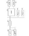
- FIG. 1 is a diagram showing a configuration of a viewing information collection system according to Embodiment 1 of the present invention.
- the viewing information collection system includes a receiving terminal 100, a user detection device 200, a display device 300, a remote media player 400, a remote media server 500, a content server 600, a viewing information totaling server 700, and an IP network 800.
- the receiving terminal 100, the remote media player 400, the remote media server 500, the content server 600, and the viewing information totaling server 700 are connected via the IP network 800, and the user detecting device 200 and the display device 300 are connected to the receiving terminal 100. It is connected.
- the content server 600 and the viewing information totaling server 700 will be described as configurations on the service provider side, but can be changed as appropriate.
- the receiving terminal 100 receives content provided by the content server 600 of the service provider via the IP network 800.
- the user detection device 200 detects whether or not the user is present at a position where the display device 300 can be viewed.
- the user detection device 200 includes, for example, a camera, and detects whether a user exists by analyzing a video shot by the camera. You may comprise so that the number of users, sex, age, etc. may be detected and stored besides user presence as user information. Also, motion sensors that do not use video information for user detection, temperature sensors, human sensors such as infrared rays, ultrasonic waves, and visible light, or user operations (for example, operations for identifying each user using a remote controller, etc.) It may be used.
- the user detection device 200 may be built in the receiving terminal 100.
- the display device 300 is connected to the receiving terminal 100 using an HDMI (High-Definition Multimedia Interface) cable or the like, and displays the content received by the receiving terminal 100.
- HDMI High-Definition Multimedia Interface
- the receiving terminal 100 can grasp the state of the display device 300, and the content display state of the display device 300 can be detected from the receiving terminal 100 side.
- the display device 300 may be built in the receiving terminal 100. Even when the display device 300 is built in the receiving terminal 100, the receiving terminal 100 can be configured to detect the content display state.
- the remote media player 400 displays the received content. Furthermore, it can be used in various ways other than displaying the received content with advanced functions. For example, the remote media player 400 accesses the receiving terminal 100 located in a different place such as a different room, outputs an acquisition request for recorded content or content being broadcast, and plays and displays the acquired content. As a result, the receiving terminal 100 can collect viewing information when the content is played back by the remote media player 400 even when the received content is not viewed during broadcasting.
- the remote media server 500 is a storage server device that is installed in a remote place such as a room different from the receiving terminal 100 and stores contents when the receiving terminal 100 is backed up or when the capacity of the receiving terminal 100 is insufficient. is there.
- the receiving terminal 100 detects the data transmission to and from the remote media server 500, thereby grasping the copy or movement of the content and managing it as viewing information with high importance.
- the content server 600 on the service provider side provides the receiving terminal 100 with a TV content service, other content providing services, interactive services, and the like.
- TV content services program broadcasting and VOD (Video On Demand) are provided, and as other content providing services, music, e-books, news, weather, photos, etc., games and applications are provided as interactive services.
- VOD Video On Demand
- the viewing information totaling server 700 transmits the collection / report pattern setting specifying the configuration for collecting viewing information and the configuration for reporting to the receiving terminal 100 of each subscriber who subscribes to the service provider.
- Configure settings related to viewing information collection and reporting for example, settings such as the type of viewing information to be collected, the collection frequency, and the reporting frequency of the collected viewing information are described.
- the viewing information to be collected may contain personal information, viewing content or viewing patterns that the subscriber wants to keep private, so it can be collected with the permission of the subscriber. Also good.
- the user designates which viewing information is permitted to be collected by the user at the time of service contract, subscription to service, or change. Information specified by the user is managed on the service provider side and reflected in the collection / report pattern setting corresponding to each subscriber.
- the permission setting for collecting viewing information by the subscriber may be changed at any time.
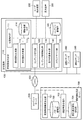
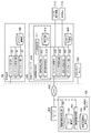
- FIG. 2 is a block diagram showing in detail the configuration of the viewing information collecting system according to Embodiment 1 of the present invention.
- the receiving terminal 100 includes a viewing information measuring unit 110, a content receiving unit 120, a content information detecting unit 130, a display state detecting unit 140, a media server unit 150, and a content storage unit 160.
- the viewing information measuring unit 110 includes a state detecting unit 111, a viewing information generating unit 112, a viewing information transmitting unit 113, and a viewing information log 114.
- the state detection unit 111 is configured to collect the viewing information permitted by the subscriber based on the collection pattern setting among the collection / report pattern settings transmitted from the viewing information totaling server 700 and received by the receiving terminal 100. Is detected. Specifically, the content reception state in the receiving terminal 100, the display state on the display device 300, the detection state of the user located in front of the display device 300, and the state of the media server unit 150 are detected.
- the viewing information generation unit 112 generates viewing information based on the state information detected by the state detection unit 111 and accumulates the viewing information in the viewing information log 114.
- the viewing information transmission unit 113 transmits the viewing information accumulated in the viewing information log 114 to the viewing information aggregation server 700 of the service provider based on the report pattern setting in the collection / report pattern setting.
- the content receiving unit 120 receives content for broadcast viewing or VOD viewing from the content server 600 via the IP network 800.
- the content information detection unit 130 acquires metadata about the content received by the content reception unit 120.
- the metadata about the content includes detailed information about the content such as a title and resolution.
- each metadata is also different. For example, broadcast time and broadcast date and time are included as metadata specific to the broadcast service.
- the state detection unit 111 refers to the reception state of the content reception unit 120 to detect whether the content is being received or not yet received. When the content is being received, the content distribution form, that is, the receiving terminal 100 Detects whether it is receiving broadcast or VOD. Furthermore, the state detection unit 111 acquires metadata about the content from the information detected by the content information detection unit 130 when the receiving terminal 100 receives a broadcast or VOD.
- the display state detection unit 140 refers to the state of the HDMI interface and detects the transmission state of the video signal to the display device 300. By confirming the display state of the display device 300, accurate viewing information can be generated. For example, a necessary condition for confirming local viewing of a normal broadcast program is that the content receiving unit 120 transmits the content being received to the display device 300. This is to prevent the occurrence of erroneous viewing information that occurs on a daily basis when the user is receiving a broadcast but is not viewing. Specifically, in order to suppress generation of erroneous viewing information that the user is watching a broadcast when only the display device 300 such as a television is turned off and the receiving terminal 100 is turned on. In addition, the display state of the display device 300 is confirmed, and viewing information is generated when the display is being performed. The detection result in the display state detection unit 140 is transmitted to the state detection unit 111.
- the media server unit 150 provides a content recording function, a content providing function, and a content copying / moving function.
- a content recording function the media server unit 150 stores the content received by the content receiving unit 120 and the metadata of the content in the content storage unit 160 and enables playback on the receiving terminal 100 or the remote media player 400. .
- viewing information regarding the recording of the content is collected and transmitted to the state detection unit 111.
- the media server unit 150 provides the recorded content stored in the content storage unit 160 to the receiving terminal 100 or the remote media player 400 connected to the network.
- the playback side receives a content list including related metadata such as a content title in order to select a recorded content, selects a recorded content to be played back from the received content list, and selects the selected content as a media server.
- Request to unit 150 the media server unit 150 provides the selected recorded content to the receiving terminal 100 or the remote media player 400.
- these processes are internally performed between the content receiving unit 120 and the media server unit 150.
- the media server unit 150 collects viewing information related to content reproduction and transmits it to the state detection unit 111.
- the media server unit 150 provides the content received by the content receiving unit 120 to the remote media player 400.
- the playback side requests playback of the content received by the content receiving unit 120.
- the media server unit 150 Upon receiving the request, provides the content received by the content receiving unit 120 to the remote media player 400.
- the media server unit 150 copies or moves the recorded content stored in the content storage unit 160 to the remote media server 500 connected to the network. This copy or movement of the recorded content occurs when the recorded content is moved to a portable device or medium, or when the remaining storage area of the content storage unit 160 is small.
- the content that is copied so as to be portable is managed as viewing information, and is counted by the viewing information counting server 700 of the service provider.
- the media server unit 150 collects viewing information regarding content copying and moving and transmits the collected viewing information to the state detection unit 111.
- the user detection device 200 detects information about the user located in front of the display device 300 and transmits the information to the state detection unit 111. Detection and output of information of the user detection device 200 is also determined by the collection / report pattern setting set by the viewing information totaling server 700, and may be strictly limited. When the detection and output of the user detection device 200 are severely limited, the user detection device 200 notifies only the presence or absence of a user, for example.
- the viewing information totaling server 700 includes a viewing information configuration setting unit 701, a pattern storage unit 702, a viewing information receiving unit 703, and a total viewing information storage unit 704.
- the viewing information configuration setting unit 701 sets a collection pattern indicating the configuration of viewing information generated by the viewing information generation unit 112 of the receiving terminal 100 and a report pattern when the viewing information transmission unit 113 transmits viewing information.
- the collection / report pattern set by the viewing information configuration setting unit 701 is stored in the pattern storage unit 702.
- the viewing information configuration setting unit 701 customizes the viewing information collection pattern to the receiving terminal 100 of each user based on the viewing information collection permission determined by the subscriber at the time of service contract or service subscription / change.
- the customized collection pattern is stored in the pattern storage unit 702.
- the viewing information configuration setting unit 701 sets the timing for receiving the viewing information report from the receiving terminal 100 and stores it in the pattern storage unit 702. Report timing can be set to a fixed period, random period, immediate or on-demand. Further, when a change occurs in the collection pattern or report timing, the viewing information configuration setting unit 701 transmits information for resetting the collection / report pattern to the corresponding receiving terminal 100 and changes the setting.
- the viewing information receiving unit 703 receives viewing information collected by each receiving terminal 100 and performs total management.
- the viewing information totaled by the viewing information receiving unit 703 is stored in the total viewing information storage unit 704.
- the stored viewing information is used to improve service provision within the service provider, or is provided to a third party such as a content provider.
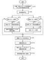
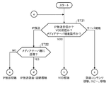
- FIG. 3 is a flowchart showing operations of the viewing information totaling server and the receiving terminal of the viewing information collecting system according to the first embodiment.
- the viewing information configuration setting unit 701 receives a viewing information collection pattern selected by the subscriber via an operation input unit (not shown) of the receiving terminal 100 or an operation input unit (not shown) of the viewing information totaling server 700.
- a new report pattern setting or setting change request managed by the service provider is received (step ST1)
- the receiving terminal 100 that has input the request related to the collection pattern and the target receiving terminal for the report pattern change are specified (step ST1). ST2).
- the viewing information configuration setting unit 701 refers to the collection / report pattern of the corresponding receiving terminal 100 stored in the pattern storage unit 702, and determines whether the collection pattern is changed among the requests received in step ST1 (step S1). Similarly, it is determined whether there is a change in the report pattern (ST3).
- step ST3 When there is a change in the collection pattern (step ST3; YES), the collection pattern setting information for setting a new collection pattern is transmitted to the viewing information generating unit 112 of the receiving terminal 100 (step ST5).
- the viewing information generation unit 112 refers to the collection pattern setting transmitted in step ST5, and notifies the state detection unit 111 of information on the collectable viewing event that has been approved by the subscriber (step ST6).
- step ST3; NO the process proceeds to step ST9.
- step ST4 If there is a change in the report pattern (step ST4; YES), report pattern setting information for setting a new report pattern is transmitted to the viewing information transmitting unit 113 of the receiving terminal 100 (step ST7).
- the viewing information transmitting unit 113 sets the report pattern transmitted in step ST7 (step ST8).
- step ST4; NO the process proceeds to step ST9.
- the state detection unit 111 detects the state of the viewing events that can be collected, and transmits it to the viewing information generation unit 112 (step ST9).
- the viewing information generation unit 112 generates viewing information based on the state detection information transmitted in step ST9 and accumulates it in the viewing information log 114 (step ST10).
- Viewing information transmission section 113 refers to the stored report pattern, and when viewing information transmission timing is reached, viewing information accumulated in viewing information log 114 is read and transmitted to viewing information totaling server 700 (step ST11). ).
- the viewing information receiving unit 703 of the viewing information totaling server 700 acquires the viewing information transmitted in step ST11, performs totalization, accumulates it in the total viewing information storage unit 704 (step ST12), and ends the process.
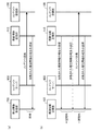
- FIG. 4 is an explanatory diagram showing a report pattern of the process of step ST11 in the flowchart of FIG. 3 described above.
- FIG. 4A is an explanatory diagram showing a case where the report pattern is set to “immediate”. In this case, the viewing information is transmitted from the viewing information transmitting unit 113 to the viewing information receiving unit 703 immediately after the content is transmitted from the content server 600 and the content receiving unit 120 receives the content.
- FIG. 4B is an explanatory diagram showing a case where the report pattern is set to “fixed intervals”. In this case, the viewing information is transmitted at regular intervals regardless of the content transmission status from the content server 600. In the explanatory diagram of FIG. 4, description of the content request performed between the content server 600 and the content receiving unit 120 is omitted.
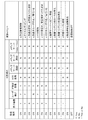
- FIG. 5 is a diagram illustrating an example of a viewing event obtained by analyzing the state detection information of the state detection unit 111.
- the state detection unit 111 identifies a viewing event based on the state detection information of the display device 300, the user detection device 200, the content reception unit 120, and the media server unit 150.
- a viewing event separates types of viewing information.
- “display device”, “user detection”, and “IP broadcast reception” are “Y” indicating a normal operation state.
- “VOD reception” and “N” indicating that the “media server (recording, playback, copy / move)” is not in operation are essential conditions. When these conditions are satisfied, the viewing event can be identified as “broadcast program viewing” with high probability. However, as shown below, there is a case of channel zapping depending on the viewing time.
- channel zapping The conditions for identifying the viewing event “channel zapping” are the same as those of the above-mentioned “broadcast program viewing”, but an event having a viewing end time shorter than the viewing start time registered as viewing information is identified as “channel zapping”. be able to.
- the viewing event “broadcast user absent / sleeping” is “Y” indicating a state in which “display device” and “IP broadcast reception” are operating normally, “user detection”, “VOD reception” and The condition is “N” indicating that the “media server (recording, playback, copy / move)” is not operating.
- the conditions for identifying the viewing events “VOD viewing”, “VOD receiving, leave receiving terminal”, “VOD user absent / sleeping” are the above-mentioned “broadcast program viewing”, “broadcast receiving, receiving terminal” “None” indicating “OFF” in “IP broadcast reception” in “Non-Broadcasting User Absent / sleeping”, and “Y” indicating “VOD reception” is operating instead. It must be a condition.
- the viewing event “copy / move to remote server” is a case where the copy or move function of the media server unit 150 is executed, and only the “media server (copy / move)” is operating as shown in FIG.
- the condition is “Y” indicating Other events executed simultaneously with copying or moving (for example, playback of recorded content or recording of content) are managed as different events, and corresponding viewing information is generated.
- the viewing event “local playback of recorded content” is a case where the local playback function of the media server unit 150 is executed.
- the “display device”, “user detection”, and “media server (playback)” The condition is “Y” indicating the operating state and “N” indicating that the “media server (recording, copy / move)” is not operating.
- the viewing event “playback of recorded content on remote terminal” is a case where media server unit 150 transmits content to remote media player 400, and only “media server (playback)” is operating as shown in FIG.
- the condition is “Y” indicating information and “N” indicating that the “media server (recording, copy / move)” is not operating.
- the viewing event “record on internal server” is a case where a broadcast program is recorded, and “Y” indicating a state in which “IP broadcast reception” and “media server (recording)” are operating as shown in FIG. Yes, “VOD reception” and “media server (playback, copy / move)” are required to be “N” indicating a non-operating state.
- the viewing event “play broadcast program on remote terminal” is a case where the received broadcast program is played on the remote media player 400, and “IP broadcast reception” and “media server (play)” operate as shown in FIG. It is a condition that “Y” indicating a state of being in operation, and “N” indicating that the “VOD reception” and “media server (playback, copy / move)” are not operating.
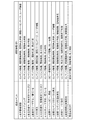
- FIG. 6 shows an example of viewing information generated corresponding to the viewing event shown in FIG.
- the viewing event is “broadcast program viewing”
- “content information, viewing start time, viewing stop time, viewing percentage, user information” is generated as viewing information.
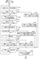
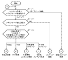
- FIG. 7 is a flowchart showing the overall operation of the state detection unit of the viewing information collecting system according to the first embodiment.
- the state detection unit 111 refers to the reception state of the content reception unit 120 and the operation state of the media server unit 150, determines whether the receiving terminal 100 receives an IP broadcast, receives a VOD, or performs a media server function. It is determined whether it is operating (step ST21).
- step ST21 it is determined whether the received IP broadcast is transmitted to the media server unit 150 (step ST22). If it has not been transmitted to the media server unit 150 (step ST22; NO), the receiving terminal 100 determines that IP broadcast viewing is being performed, and proceeds to process a. On the other hand, if it is output to the media server unit 150 (step ST22; YES), it is determined that IP broadcast recording or IP broadcast remote viewing is being performed in the media server unit 150, and the process proceeds to step d.
- step ST21 If it is determined that the VOD is received in step ST21, the receiving terminal 100 determines that VOD viewing is being performed, and proceeds to the process b. Similarly, when it is determined in step ST21 that the media server function is operating, it is determined that the recorded content is being viewed or copied or moved in the media server unit 150, and the process proceeds to process c.
- state detection for detecting a viewing event that occurs during IP broadcast viewing is performed, and information such as content information and time is collected.
- the state detection unit 111 acquires the transmission state of the video signal from the display state detection unit 140 to the display device 300 (step ST31), refers to the transmission state of the acquired video signal, and determines whether the display device 300 is in the operating state. A determination is made (step ST32).
- step ST32 When the display device 300 is in an operating state (step ST32; YES), user information relating to the user located in front of the display device 300 is acquired from the user detection device 200 (step ST33), and displayed with reference to the acquired user information.
- step ST34 It is determined whether the user is located in front of the apparatus 300 (step ST34).
- the state detection unit 111 detects that the viewing event is IP broadcast viewing, and refers to information about the content acquired from the content information detection unit 130.
- the viewing channel information and time are acquired (step ST35).
- step ST32; NO when the display device 300 is not in the operating state (step ST32; NO), the state detection unit 111 detects that the viewing mode is abnormal (while the receiving terminal is on) and acquires it from the content information detection unit 130. By referring to the information about the content, viewing channel information, time, and the like are acquired (step ST36).
- step ST34; NO the state detection unit 111 detects that the viewing mode is abnormal (the user is absent) and acquires it from the content information detection unit 130.
- step ST37 the information about the content, the viewing channel information, time, and the like are acquired (step ST37).
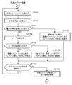
- the state detection unit 111 determines whether the receiving terminal 100 continues to receive the IP broadcast (step ST38). If the reception of the IP broadcast is continued (step ST38; YES), the process returns to step ST31 and the above-described process is repeated. On the other hand, when the reception of the IP broadcast is not continued (step ST38; NO), the reception end of the IP broadcast is detected and the reception end time is acquired (step ST39). Thereafter, the flow returns to the process of step ST21 in FIG. 7, and the above-described process is repeated.
- state detection for detecting a viewing event that occurs during VOD viewing is performed, and information such as content information and time is collected.
- the state detection unit 111 acquires the transmission state of the video signal from the display state detection unit 140 to the display device 300 (step ST41), refers to the transmission state of the acquired video signal, and determines whether the display device 300 is in the operating state. A determination is made (step ST42).
- step ST42 When the display device 300 is in an operating state (step ST42; YES), user information relating to the user located in front of the display device 300 is further acquired from the user detection device 200 (step ST43), and the acquired user information is referred to.
- step ST44 It is determined whether the user is located in front of the display device 300 (step ST44).
- step ST44; YES the state detection unit 111 detects that the viewing event is VOD viewing and acquires content information, time, and the like from the content information detection unit 130 ( Step ST45).
- step ST42 when the display device 300 is not in the operating state (step ST42; NO), the state detection unit 111 detects that the viewing mode is abnormal (while the receiving terminal is on) and acquires it from the content information detection unit 130. Information related to the content is referred to, and viewing content information and time are acquired (step ST46).
- step ST44 When the user is not located in front of the display device 300 (step ST44; NO), the state detection unit 111 detects that the viewing mode is abnormal (the user is absent) and the content information from the content information detection unit 130. And time etc. are acquired (step ST47).
- step ST48 determines whether the receiving terminal 100 continues to receive VOD. If VOD reception is continued (step ST48; YES), the process returns to step ST41 and the above-described process is repeated. On the other hand, when VOD reception is not continued (step ST48; NO), VOD reception completion is detected and reception completion time is acquired. Thereafter, the flow returns to the process of step ST21 in FIG. 7, and the above-described process is repeated (step ST49).
- process c status detection is performed to detect a viewing event that occurs during viewing, copying, or moving processing of recorded content, and information such as content information and time is collected.
- the state detection unit 111 acquires information related to content reproduction from the media server unit 150 (step ST51), refers to the acquired information related to content reproduction, and determines whether the recorded content is transmitted to the remote media player 400 (step ST51). ST52).
- step ST52 When the recorded content has not been transmitted to the remote media player 400 (step ST52; NO), information related to copying or moving of the content is further acquired from the media server unit 150 (step ST53), and the recorded content is referenced with reference to the acquired information. Is transmitted to the remote media server 500 (step ST54).
- the state detection unit 111 acquires the transmission state of the video signal from the display state detection unit 140 to the display device 300 (step ST55). With reference to the transmission state of the acquired video signal, it is determined whether the display device 300 is in an operating state (step ST56). When the display device 300 is in an operating state (step ST56; YES), the state detection unit 111 further acquires user information regarding the user located in front of the display device 300 from the user detection device 200 (step ST57), and acquires the acquired user. It is determined whether the user is located in front of the display device 300 with reference to the information (step ST58).
- the state detection unit 111 detects that the viewing event is local reproduction of the recorded content, and also receives the content information and time from the content information detection unit 130. Obtain (step ST59).
- the state detection unit 111 detects that the viewing event is a reproduction of the recorded content by the remote media player 400, and also the content information detection unit. Content information, time, etc. are acquired from 130 (step ST60).
- the state detection unit 111 detects that the viewing event is a copy or move of the recorded content, and from the content information detection unit 130. Content information, time, and the like are acquired (step ST61).
- step ST56 when display device 300 is not in the operating state (step ST56; NO), state detection unit 111 detects that the viewing mode is abnormal (the receiving terminal is still on) and content information from content information detection unit 130. And time etc. are acquired (step ST62).
- step ST58 when the user is not located in front of the display device 300 (step ST58; NO), the state detection unit 111 detects that the viewing mode is abnormal (the user is absent) and the content information from the content information detection unit 130. And time etc. are acquired (step ST63).
- the state detection unit 111 determines whether the media server unit 150 continues the transmission process of the recorded content (step ST64). When the recording content transmission process continues (step ST64; YES), the process returns to step ST51 and the above-described process is repeated. On the other hand, when the recording content transmission processing is not continued (step ST64; NO), the completion of the recording content processing is detected and the processing completion time is acquired (step ST65). Thereafter, the flow returns to the process of step ST21 in FIG. 7, and the above-described process is repeated.
- state detection is performed to detect a viewing event that occurs in IP broadcast recording or IP broadcast remote viewing, and information such as content information and time is collected.
- the state detection unit 111 acquires information related to IP broadcast recording from the media server unit 150 (step ST71), refers to the acquired IP broadcast recording information, and determines whether the IP broadcast is being recorded (step ST72). . If the IP broadcast is not being recorded (step ST72; NO), information related to remote playback in the IP broadcast media player 400 is further acquired from the media server unit 150 (step ST73), and the acquired IP broadcast remote playback information is referred to. Then, it is determined whether the IP broadcast is transmitted to the remote media player 400 (step ST74). When the IP broadcast is not transmitted to the remote media player 400 (step ST74; NO), the process proceeds to step ST77.
- the state detection unit 111 detects that the viewing event is the recording of the IP broadcast and acquires content information, time, and the like from the content information detection unit 130. (Step ST75). If the IP broadcast is transmitted to the remote media player 400 (step ST74; YES), the state detection unit 111 detects that the viewing event is remote playback of the IP broadcast, and the content information from the content information detection unit 130. And the time etc. are acquired (step ST76).
- the state detection unit 111 determines whether the receiving terminal 100 continues to receive the IP broadcast (step ST77).
- step ST77 the process returns to step ST71 and the above-described process is repeated.
- step ST78 the reception end of the IP broadcast is detected and the reception end time is acquired (step ST78). Thereafter, the flow returns to the process of step ST21 in FIG. 7, and the above-described process is repeated.
- information about user detection of the user detection device 200 information about the display state of the display device 300 from the display state detection unit 140, and information about the processing state of content from the media server unit 150 And so forth, and a state detection unit 111 that detects the state of the receiving terminal 100 and a viewing information generation unit 112 that generates viewing information based on the state of the receiving terminal 100 detected by the state detection unit 111. Therefore, accurate and abundant viewing information can be generated. As a result, it is possible to accurately provide information useful for tabulating viewing information for the service provider side (viewing information totaling server 700).
- Viewing information can be collected while protecting user privacy.
- Embodiment 2 in order to generate accurate and abundant viewing information regarding the remote media player 400, the remote media player 400 has the same configuration as the viewing information measuring unit 110 shown in the first embodiment. Show.
- the remote media player 400 receives the content transmitted from the content server 600, the receiving terminal 100, and the other remote media server 500, reproduces it in real time, or reproduces it after temporarily storing it.
- By monitoring the internal state of the remote media player 400 such as the playback state and the storage state, it is possible to collect detailed viewing information based on the viewing history (partial content viewing or all content viewing) and the number of times of viewing. .
- FIG. 12 is a diagram showing a configuration of a viewing information collecting system according to Embodiment 2 of the present invention.
- the viewing information collection system according to the second embodiment includes a receiving terminal 100, a remote media player 400, a user detection device 210, a display device 310, a remote media server 500, a content server 600, a viewing information totaling server 700, and an IP network 800. ing.
- the receiving terminal 100, the remote media player 400, the remote media server 500, the content server 600, and the viewing information totaling server 700 are connected via the IP network 800, and the user detection device 210 and the display device 310 are connected to the remote media player 400. It is connected to the.
- the content server 600 and the viewing information totaling server 700 will be described as configurations on the service provider side, but can be changed as appropriate.
- the receiving terminal 100 receives the content provided by the content server 600 of the service provider via the IP network 800.
- the received content is transmitted to the remote media player 400 in real time, or is temporarily stored in the receiving terminal 100 and then transmitted to the remote media player 400.
- the user detection device 200 and the display device 300 are connected as in the receiving terminal 100 shown in FIG. 1 of the first embodiment, and the received content is also received at the receiving terminal 100. It may be configured to reproduce and collect viewing information.
- the remote media player 400 is composed of, for example, a portable receiving terminal and has advanced functions that can be used in various ways as in the first embodiment. Specifically, in addition to the function of receiving and playing back or recording the content provided by the content server 600 of the service provider via the IP network 800, the receiving terminal 100 or remote media located in a remote place such as a different room in the house The broadcast content or recorded content provided from the server 500 is acquired and reproduced. Thereby, even when the content is not viewed at the time of broadcasting, viewing information can be collected when the content is played back by the remote media player 400.
- the user detection device 210 detects whether or not the user is present at a position where the display device 310 can be viewed.
- the user detection device 210 includes a camera, for example, and detects whether there is a user by analyzing video captured by the camera. You may comprise so that the number of users, sex, age, etc. may be detected and stored besides user presence as user information. Also, motion sensors that do not use video information for user detection, temperature sensors, human sensors such as infrared rays, ultrasonic waves, and visible light, or user operations (for example, operations for identifying each user using a remote controller, etc.) It may be used.
- the user detection device 210 may be built in the remote media player 400.
- the display device 310 is connected to the remote media player 400 using an HDMI cable or the like as in the first embodiment, and displays the content received by the remote media player 400.
- HDMI the remote media player 400 can grasp the state of the display device 310, and the content display state of the display device 310 can be detected from the remote media player 400 side.
- the display device 310 may be built in the remote media player 400. Even when the display device 310 is built in the remote media player 400, the remote media player 400 can be configured to detect the content display state.
- the remote media server 500 provides the accumulated content to the remote media player 400 and other terminals in addition to the configuration of the first embodiment. Since the content server 600 and the viewing information totaling server 700 are the same as those in the first embodiment, description thereof is omitted.
- FIG. 13 is a block diagram showing in detail the configuration of the viewing information collecting system according to the second embodiment of the present invention.
- the receiving terminal 100 shown in FIG. 13 includes a content receiving unit 120, a content information detection unit 130, a media server unit 150 ′, and a content storage unit 160.
- the content receiving unit 120, the content information detecting unit 130, and the content accumulating unit 160 have the same configuration as that of the first embodiment described above.
- the media server unit 150 ′ provides the recorded content stored in the content storage unit 160 to the remote media player 400 as in the first embodiment, and the content received by the content receiving unit 120 to the remote media player 400. Provided, but does not collect viewing information related to content playback.
- the user detection device 200 and the display device 300 are connected to each other, and the viewing information measuring unit 110 that measures the viewing information is provided, and the receiving terminal 100 having the same function as the first embodiment is configured. May be.
- the remote media player 400 includes a viewing information measurement unit 410, a content reception unit 420, a content information detection unit 430, a display state detection unit 440, a media server unit 450, and a content storage unit 460. Further, the viewing information measuring unit 410 includes a state detecting unit 411, a viewing information generating unit 412, a viewing information transmitting unit 413, and a viewing information log 414.
- the state detection unit 411 collects viewing information permitted by the subscriber based on the collection pattern setting among the collection / report pattern settings transmitted from the receiving terminal 100 or the viewing information totaling server 700 and received by the remote media player 400. The status of each configuration is detected. Specifically, the content reception state in the remote media player 400, the display state on the display device 310, and the detection state of the user located in front of the display device 310 are detected.
- the viewing information generation unit 412 generates viewing information based on the state information detected by the state detection unit 411 and stores it in the viewing information log 414.
- the viewing information transmission unit 413 transmits the viewing information accumulated in the viewing information log 414 to the viewing information aggregation server 700 of the service provider based on the report pattern setting in the collection / report pattern setting.
- the receiving terminal 100 sets a collection / report pattern
- the viewing information transmitting unit 413 transmits the viewing information accumulated in the viewing information log 414 to the receiving terminal 100. May be.
- the content receiving unit 420 receives content provided by the receiving terminal 100 or the remote media server 500 located in a remote place such as a different room in the house. Also, content for broadcast viewing or VOD viewing is received from the content server 600 via the IP network 800.
- the content information detection unit 430 acquires metadata related to the content received by the content reception unit 420.
- the metadata about the content includes detailed information about the content such as a title and resolution.
- each metadata is also different. For example, broadcast time and broadcast date and time are included as metadata specific to the broadcast service.
- metadata related to recording for example, date and time, recording image quality, and the like are included.
- the state detection unit 411 refers to the reception state of the content reception unit 420 to detect whether the content is being received or not yet received.
- the content distribution form that is, the remote media player It is detected whether 400 is receiving broadcast content or stored content from the receiving terminal 100, receiving stored content from the remote media server 500, or receiving broadcast content or VOD content from the content server 600.
- the state detection unit 411 acquires metadata about the content from the information detected by the content information detection unit 430 when receiving broadcast content, stored content, or VOD content.
- the display state detection unit 440 refers to the state of the HDMI interface and detects the transmission state of the video signal to the display device 310. By confirming the display state of the display device 310, accurate viewing information can be generated. For example, a necessary condition for confirming local viewing of a normal broadcast program is that the content receiving unit 420 transmits the content being received from the receiving terminal 100 or the content server 600 to the display device 310. This is to prevent the occurrence of erroneous viewing information that occurs on a daily basis when the user is receiving a broadcast but is not viewing.
- the display state of the display device 310 is confirmed, and the viewing information is generated when the display is being performed.
- the detection result in the display state detection unit 440 is transmitted to the state detection unit 411.
- the media server unit 450 supports a content recording function and a content providing function.
- a content recording function the media server unit 450 stores the content received by the content receiving unit 420 and metadata of the content in the content storage unit 460 so that the display device 310 can reproduce the content.
- viewing information regarding the recording of the content is collected and transmitted to the state detection unit 411.
- the media server unit 450 provides the recorded content stored in the content storage unit 460 to the remote media player 400.
- the recorded content to be reproduced on the remote media player 400 side is selected and requested to the media server unit 450.
- the media server unit 450 Upon receiving the request, the media server unit 450 provides the selected recorded content to the remote media player 400.
- These processes are internally performed between the content receiving unit 420 and the media server unit 450.
- the media server unit 450 collects viewing information related to content reproduction and transmits it to the state detection unit 411.
- the viewing information totaling server 700 includes a viewing information configuration setting unit 701, a pattern storage unit 702, a viewing information receiving unit 703, and a total viewing information storage unit 704.
- the viewing information configuration setting unit 701 sets a collection pattern indicating the configuration of viewing information generated by the viewing information generation unit 412 of the remote media player 400 and a report pattern when the viewing information transmission unit 413 transmits viewing information.
- the collection / report pattern set by the viewing information configuration setting unit 701 is stored in the pattern storage unit 702.
- the viewing information configuration setting unit 701 customizes the viewing information collection pattern to the remote media player 400 of each user based on the viewing information collection permission determined by the subscriber at the time of service contract or service subscription / change. Then, the customized collection pattern is stored in the pattern storage unit 702. Also, the viewing information configuration setting unit 701 sets the timing for receiving the viewing information report from the remote media player 400 and accumulates it in the pattern accumulation unit 702. Report timing can be set to a fixed period, random period, immediate or on-demand. When a change occurs in the collection pattern or report timing, the viewing information configuration setting unit 701 transmits information for resetting the collection / report pattern to the corresponding remote media player 400 to change the setting.
- the viewing information receiving unit 703 receives viewing information collected by each remote media player 400 and totals and manages it.
- the viewing information totaled by the viewing information receiving unit 703 is stored in the total viewing information storage unit 704.
- the stored viewing information is used to improve service provision within the service provider, or is provided to a third party such as a content provider.
- FIG. 14 is a flowchart showing operations of the viewing information totaling server and the remote media player of the viewing information collecting system according to the second embodiment.
- the viewing information configuration setting unit 701 uses a viewing information collection pattern selected by the subscriber via an operation input unit (not shown) of the remote media player 400 or an operation input unit (not shown) of the viewing information totaling server 700.
- a report pattern new setting or setting change request managed by the service provider is received (step ST101)
- the remote media player 400 that has input the request related to the collection pattern and the target media player for which the report pattern is to be changed are specified. (Step ST102).
- the viewing information configuration setting unit 701 refers to the collection / report pattern of the corresponding remote media player 400 stored in the pattern storage unit 702, and determines whether the collection pattern of the request received in step ST101 has changed ( Similarly, it is determined whether there is a change in the report pattern (step ST104).
- step ST103 When there is a change in the collection pattern (step ST103; YES), the collection pattern setting information for setting a new collection pattern is transmitted to the viewing information generation unit 412 of the remote media player 400 (step ST105).
- the viewing information generation unit 412 refers to the collection pattern setting transmitted in step ST105, and notifies the state detection unit 411 of information on the collectable viewing event that has been approved by the subscriber (step ST106).
- step ST103 determines the collection pattern setting transmitted in step ST105, and notifies the state detection unit 411 of information on the collectable viewing event that has been approved by the subscriber.
- step ST104 If there is a change in the report pattern (step ST104; YES), report pattern setting information for setting a new report pattern is transmitted to the viewing information transmission unit 413 of the remote media player 400 (step ST107).
- the viewing information transmission unit 413 sets the report pattern transmitted in step ST107 (step ST108).
- step ST104; NO the process proceeds to step ST109.
- the state detection unit 411 detects the state of the viewable viewing events and transmits it to the viewing information generation unit 412 (step ST109).
- the viewing information generation unit 412 generates viewing information based on the state detection information transmitted in step ST109, and accumulates it in the viewing information log 414 (step ST110).
- Viewing information transmitting section 413 determines whether or not it is connected to IP network 800 (step ST111). If not connected (step ST111; NO), it returns to the determination process of step ST111, and a connection is detected. Wait until On the other hand, when connected to IP network 800 (step ST111; YES), viewing information transmission section 413 refers to the stored report pattern, and accumulates in viewing information log 414 when viewing information transmission timing is reached.
- the viewing information thus read out is transmitted to the viewing information totaling server 700 (step ST112).
- the viewing information receiving unit 703 of the viewing information totaling server 700 acquires the viewing information transmitted in step ST112, totals it, accumulates it in the total viewing information storage unit 704 (step ST113), and ends the process.
- FIG. 15 is an explanatory diagram showing a report pattern of the process of step ST112 in the flowchart of FIG. 14 described above.
- FIG. 15A is an explanatory diagram showing a case where the report pattern is set to “immediate”.
- the content information is transmitted from any one of the content server 600, the receiving terminal 100, the remote media server 500, and the content storage unit 460, and immediately after the content is received by the content reception unit 420, the viewing information transmission unit 413 receives the viewing information. Is transmitted to the viewing information receiving unit 703.
- FIG. 15B is an explanatory diagram showing a case where the report pattern is set to “fixed interval”.
- viewing information is transmitted at regular intervals regardless of the content transmission status from any of the content server 600, the receiving terminal 100, the remote media server 500, and the content storage unit 460.
- the description of the content request performed between any of the content server 600, the receiving terminal 100, the remote media server 500, and the content storage unit 460 and the content receiving unit 420 is omitted.
- the remote media player 400 is connected to the IP network 800.
- FIGS. 16 and 17 are explanatory diagrams showing viewing events and viewing information corresponding to the viewing events of the remote media player 400 of the viewing information collection system according to the second embodiment.
- FIG. 16 is a diagram illustrating an example of a viewing event obtained by analyzing the state detection information of the state detection unit 411.
- the state detection unit 411 identifies a viewing event based on the state detection information of the display device 310, the user detection device 210, the content reception unit 420, and the media server unit 450.
- the state detection information and the viewing event to be performed are “a. Broadcast program viewing”, “a. Channel zapping”, “a. While receiving broadcast, keep receiving terminal”, “a. ... “No user / sleeping during broadcast” and “b. VOD viewing”, “b. Receiving VOD, keep receiving terminal”, “b. No user / sleeping during VOD” Since the state detection information corresponding to the viewing event is the same as in the first embodiment, in FIG. And b. Are described together and the description is omitted.
- the content receiving unit 420 performs “accumulated content reception” and “other content reception” in addition to “IP broadcast reception” and “VOD reception”. “Stored content reception” and “other content reception” fields are added, but when viewing broadcast programs or VOD in real time, “stored content reception” and “other content reception” are not operating. “N” indicating “Other content” includes “IP broadcasting” and “VOD”, which are mainly TV programs and movies, and music, e-books, E-news, weather, photos, and games that are not included in the “accumulated content”. Real-time interactive or downloadable content and applications.
- a viewing event for viewing content stored in the receiving terminal 100 or the remote media server 500 which is a characteristic configuration of the second embodiment, will be described in detail.
- “display device”, “user detection”, and “stored content reception” are “Y” indicating a normal operation
- IP broadcast reception”, “VOD reception”, “media server (recording, playback)” and “other content reception” must be “N” indicating information that is not operating.
- the viewing event can be identified as “viewing externally stored content” with a high probability.
- the viewing event “externally stored content being received, user absent / sleeping” is “Y” indicating a state in which “display device” and “stored content received” are operating normally, and “user detection”, “ The condition is that “IP broadcast reception”, “VOD reception”, “media server (recording / playback)”, and “other content reception” are “N” indicating that they are not operating.
- IP broadcast reception is normal for broadcast program recording
- VOD reception and “media server (recording)” are normal for VOD recording. Is “Y” indicating the operating state, “VOD reception” for broadcast program recording, “IP broadcast reception”, “stored content reception”, “media server (playback)” and “other content reception” for VOD recording. It is an essential condition that “N” indicates a state of not operating. Note that “external storage content storage” can be identified regardless of the presence or absence of “display device” and “user detection”. For example, “display device” and “user detection” indicate a state in which the operation is normal.
- “externally stored content recording” In order to identify the viewing event “externally stored content recording”, as shown in FIG. 16, “stored content reception” and “media server (recording)” are “Y” indicating a normal operation state, It is an indispensable condition that “IP broadcast reception”, “VOD reception”, “media server (playback)”, and “other content reception” are “N” indicating that they are not operating. Note that “external storage content storage” can be identified regardless of the presence or absence of “display device” and “user detection”. For example, “display device” and “user detection” indicate a state in which the operation is normal.
- the local playback function of the media server unit 450 is executed. As shown in FIG. 16, “display device”, “user detection”, and “media server ( “Play” “indicates the operating state, and” IP broadcast reception ",” VOD reception “,” stored content reception “,” media server (recording) ", and” other content reception "operate The condition is “N” indicating a state of not being performed.
- “media server (recording)” and “other content reception” are “Y” indicating a normal operation state
- the condition is that the IP broadcast reception, the VOD reception, the stored content reception, and the media server (playback) are “N” indicating that they are not operating.
- the presence or absence of “display device” and “user detection” does not matter.
- FIG. 17 shows an example of viewing information generated corresponding to the viewing event shown in FIG. Since the remote media player 400 according to the second embodiment can disconnect the network connection, network connection information (inside and outside the house) is additionally generated as viewing information. For example, if the viewing information is “viewing externally stored content”, the viewing information is “content information”, “viewing start time”, “viewing stop time”, “viewing percentage”, “viewing count”, “recording start” “Time”, “Recording end time”, “User information”, and “Network connection information (inside and outside the house)” are generated.
- the viewing information is “viewing externally stored content”
- the viewing information is “content information”, “viewing start time”, “viewing stop time”, “viewing percentage”, “viewing count”, “recording start” “Time”, “Recording end time”, “User information”, and “Network connection information (inside and outside the house)” are generated.
- FIG. 18 is a flowchart showing the overall operation of the state detection unit of the remote media player of the viewing information collecting system according to the second embodiment.
- the state detection unit 411 refers to the reception state of the content reception unit 420 and the operation state of the media server unit 450, and determines whether the content is received or the media server function is operating (step ST121).
- step ST121 If it is determined in step ST121 that the content is received, it is determined whether the received content is transmitted to the media server unit 450 (step ST122). If not transmitted to media server unit 450 (step ST122; NO), it is further determined whether IP broadcast is received, VOD is received, or externally stored content is received (step ST123). If it is determined in step ST123 that the IP broadcast is received, the remote media player 400 determines that the IP broadcast is being viewed, and the process proceeds to process a '. If it is determined in step ST123 that the VOD broadcast is received, the remote media player 400 determines that VOD viewing is being performed, and the process proceeds to process b '.
- step ST123 If it is determined in step ST123 that externally stored content is received, it is determined that the externally stored content is being viewed, and the process proceeds to process f. If it is determined in step ST123 that other content is received, it is determined that other content is being played back, and the process proceeds to process i.
- step ST122 determines that the received content has been transmitted to media server unit 450 (step ST122; YES).
- IP broadcast recording, VOD recording, externally stored content recording, or the like of content is performed in media server unit 450. It is determined that content recording is being performed, and the process proceeds to process g. If it is determined in step ST121 that the media server function is operating, the media server unit 450 determines that the recorded content is being viewed, and the process proceeds to process h.
- the processing a ′ and the processing b ′ are the same as the flowcharts shown in FIG. 8 and FIG. 9 of the first embodiment, and only the main body that performs the processing is changed from the receiving terminal 100 to the remote media player 400. Are different, the description of the flowchart is omitted.
- the state detection unit 411 of the remote media player 400 generates a viewing event that occurs in IP broadcast viewing or a VOD viewing based on the operation state of the display device 310 and the user detection device 210. Status detection for detecting viewing events is performed, and information such as content information and time is collected.
- state detection is performed to detect a viewing event that occurs when viewing externally stored content, and information such as content information and time is collected.
- the state detection unit 411 acquires the transmission state of the video signal from the display state detection unit 440 to the display device 310 (step ST131), refers to the transmission state of the acquired video signal, and determines whether the display device 310 is in the operating state. A determination is made (step ST132).
- display device 310 is in an operating state (step ST132; YES)
- user information relating to the user located in front of display device 310 is acquired from user detection device 210 (step ST133), and the acquired user information is referred to.
- step ST134 It is determined whether the user is located in front of the display device 310 (step ST134).
- state detection unit 411 detects that the viewing event is viewing of externally stored content, and acquires content information, time, and the like from content information detection unit 430. (Step ST135).
- step ST132 when display device 310 is not in an operating state (step ST132; NO), state detection unit 411 detects that the viewing mode is abnormal (while the remote media player is on) and acquires it from content information detection unit 430.
- the information about the content to be viewed is referred to, and the viewing content information and time are acquired (step ST136).
- step ST134 the state detection unit 411 detects that the viewing mode is abnormal (the user is absent) and the content information from the content information detection unit 430. And time etc. are acquired (step ST137).
- step ST138 determines whether the remote media player 400 continues to receive externally stored content.
- step ST138; YES determines whether the remote media player 400 continues to receive externally stored content.
- step ST138; NO the processing returns to step ST131 and the above-described processing is repeated.
- step ST138; NO completion of external storage content reception is detected and reception completion time is acquired. Thereafter, the flow returns to the process of step ST121 in FIG. 18, and the above-described process is repeated (step ST139).
- process g status detection is performed to detect viewing events that occur in IP broadcast recording, VOD recording, externally stored content recording or other content recording, and information such as content information and time is collected.
- the same processing is performed when any of IP broadcast recording, VOD recording, other content recording, and externally stored content recording is performed, and therefore, the externally stored content recording will be described as an example.
- step ST141 When the state detection unit 411 acquires information related to the recording of the externally stored content from the media server unit 450 (step ST141), the state detection unit 411 detects that the viewing event is a recording of the externally stored content, and the content information detection unit Content information, time, and the like are acquired from 430 (step ST142). Thereafter, state detection section 411 determines whether remote media player 400 continues to receive externally stored content (step ST143). When the reception of the externally stored content is continued (step ST143; YES), the process returns to step ST141 and the above-described process is repeated. On the other hand, when the reception of the external stored content is not continued (step ST143; NO), the reception end time of the external stored content is detected and the reception end time is acquired (step ST144). Thereafter, the flow returns to the process of step ST121 in FIG. 18, and the above-described process is repeated.
- state detection for detecting a viewing event that occurs when viewing the recorded content is performed, and information such as content information and time is collected.
- the state detection unit 411 acquires information related to content reproduction from the media server unit 450 (step ST151)
- the state detection unit 411 further acquires the transmission state of the video signal from the display state detection unit 440 to the display device 310 (step ST152). With reference to the transmission state of the video signal, it is determined whether the display device 310 is in an operating state (step ST153).
- the state detection unit 411 When the display device 310 is in an operating state (step ST153; YES), the state detection unit 411 further acquires user information regarding the user located in front of the display device 310 from the user detection device 210 (step ST154). It is determined whether the user is located in front of the display device 310 with reference to the information (step ST155). When the user is located in front of the display device 310 (step ST155; YES), the state detection unit 411 detects that the viewing event is local reproduction of the recorded content, and also receives the content information and time from the content information detection unit 430. Obtain (step ST156), proceed to the process of step ST159.
- step ST153 when display device 310 is not in the operating state (step ST153; NO), state detection unit 411 detects that the viewing mode is abnormal (while the remote media player is turned on), and content from content information detection unit 430 Information, time, etc. are acquired (step ST157) and it progresses to the process of step ST159.
- step ST155 When the user is not located in front of display device 310 (step ST155; NO), state detection unit 411 detects that the viewing mode is abnormal (the user is absent), and content information from content information detection unit 430. And time etc. are acquired (step ST158) and it progresses to the process of step ST159.
- the state detection unit 411 determines whether the media server unit 450 continues the transmission process of the recorded content (step ST159).
- the recording content transmission process continues (step ST159; YES)
- the process returns to step ST151 and the above-described process is repeated.
- the recording content transmission processing is not continued (step ST159; NO)
- the completion of the recording content processing is detected and the processing completion time is acquired (step ST160).
- the flow returns to the process of step ST121 in FIG. 18, and the above-described process is repeated.
- state detection is performed to detect a viewing event that occurs during reproduction of other content, and information such as content information and time is collected.
- the state detection unit 411 acquires information related to other content reproduction from the content reception unit 420 (step ST161), and acquires content information, time, and the like from the content information detection unit 430 (step ST162). Thereafter, state detection section 411 determines whether remote media player 400 continues to receive other contents (step ST163). When other content reception is continued (step ST163; YES), the process returns to step ST161 and the above-described process is repeated.
- step ST163 when other content reception is not continued (step ST163; NO), the completion of other content reception is detected and the reception completion time is acquired (step ST164). Thereafter, the flow returns to the process of step ST121 in FIG. 18, and the above-described process is repeated.
- information related to user detection of the user detection device 210 information related to the display status in the display device 310 from the display status detection unit 440, and information related to the processing status of content from the media server unit 450
- a state detection unit 411 that detects the state of the remote media player 400
- a viewing information generation unit 412 that generates viewing information based on the state of the remote media player 400 detected by the state detection unit 411. Therefore, it is possible to generate accurate and abundant viewing information in the remote media player 400. As a result, it is possible to accurately provide information useful for tabulating viewing information for the service provider side (viewing information totaling server 700).
- the collected viewing is performed when the connection with the network is restored. Since the information is reported to the service provider (viewing information totaling server 700), accurate viewing information is generated even when the network connection is cut off and the content stored in the remote media player 400 is viewed. It can be provided to the service provider side.
- the receiving terminal, the viewing information collection system, and the viewing information collection method according to the present invention include information relating to user detection of a user detection device, information relating to a display state in a display device from a display state detection unit, and information relating to a content processing state from a media server unit And a state detection unit that detects the state of the receiving terminal and a viewing information generation unit that generates viewing information based on the state of the receiving terminal detected by the state detection unit. Since information can be generated and information useful for tabulating viewing information can be accurately provided for the service provider side (viewing information totaling server), viewing that collects viewer viewing information in the content distribution service
- the present invention can be applied to an information collection system and a viewing information collection method.
- 100 receiving terminal 110, 410 viewing information measuring unit, 111, 411 state detecting unit, 112, 412 viewing information generating unit, 113, 413 viewing information transmitting unit, 114, 414 viewing information log, 120, 420 content receiving unit, 130 , 430 content information detection unit, 140, 440 display state detection unit, 150, 150 ', 450 media server unit, 160, 460 content storage unit, 200, 210 user detection device, 300, 310 display device, 400 remote media player, 500 remote media server, 600 content server, 700 viewing information totaling server, 701 viewing information configuration setting unit, 702 pattern storage unit, 703 viewing information receiving unit, 704 total viewing information storage unit, 800 IP network.
Landscapes
- Engineering & Computer Science (AREA)
- Signal Processing (AREA)
- Multimedia (AREA)
- Social Psychology (AREA)
- Health & Medical Sciences (AREA)
- General Health & Medical Sciences (AREA)
- Databases & Information Systems (AREA)
- Computer Networks & Wireless Communication (AREA)
- Business, Economics & Management (AREA)
- Marketing (AREA)
- Two-Way Televisions, Distribution Of Moving Picture Or The Like (AREA)
- Testing, Inspecting, Measuring Of Stereoscopic Televisions And Televisions (AREA)
- Information Transfer Between Computers (AREA)
- Television Signal Processing For Recording (AREA)
Abstract
Description
実施の形態1.
図1は、この発明の実施の形態1による視聴情報収集システムの構成を示す図である。
視聴情報収集システムは、受信端末100、ユーザ検出装置200、表示装置300、遠隔メディアプレーヤ400、遠隔メディアサーバ500、コンテンツサーバ600、視聴情報集計サーバ700およびIPネットワーク800で構成されている。
受信端末100、遠隔メディアプレーヤ400、遠隔メディアサーバ500、コンテンツサーバ600および視聴情報集計サーバ700は、それぞれIPネットワーク800を介して接続しており、ユーザ検出装置200および表示装置300は受信端末100に接続されている。なお、以下では、コンテンツサーバ600および視聴情報集計サーバ700は、サービスプロバイダ側の構成として説明するが、適宜変更可能である。
ユーザ検出装置200は、表示装置300を視認可能な位置にユーザが存在するか否かを検出する。ユーザ検出装置200は、例えばカメラを備え、カメラにより撮影した映像を解析することによりユーザが存在するか否かを検出する。ユーザ情報としてユーザの存在以外にユーザの数、性別、年齢などを検出、格納するように構成してもよい。またユーザの検出に映像情報を利用しない動きセンサ、温度センサ、赤外線や超音波、可視光などの人感センサ、またはユーザ操作(例えば、リモコンなどを使った各ユーザを識別するための操作)を用いてもよい。また、近年プライバシー問題を考慮して、ユーザ検出装置200に内蔵したカメラにより撮影を行うが、撮影した映像情報を出力せず、ユーザの検出結果のみ(例えば、「ユーザ検出」、「ユーザ不在」、「ユーザ3人検出」など)出力するように構成してもよい。なお、ユーザ検出装置200は受信端末100に内蔵してもよい。
受信端末100は、視聴情報測定部110、コンテンツ受信部120、コンテンツ情報検出部130、表示状態検出部140、メディアサーバ部150およびコンテンツ蓄積部160で構成されている。さらに視聴情報測定部110は、状態検出部111、視聴情報生成部112、視聴情報送信部113および視聴情報ログ114で構成されている。
状態検出部111は、コンテンツ受信部120の受信状態を参照してコンテンツ受信中であるか、未受信であるかを検出し、コンテンツ受信中である場合にはコンテンツの配信形態、すなわち受信端末100が放送を受信しているか、VODを受信しているかを検出する。さらに状態検出部111は受信端末100が放送あるいはVODを受信している場合にコンテンツ情報検出部130が検出した情報からコンテンツに関するメタデータを取得する。
まず、コンテンツ録画機能として、メディアサーバ部150は、コンテンツ受信部120が受信したコンテンツおよび当該コンテンツのメタデータをコンテンツ蓄積部160に格納し、受信端末100または遠隔メディアプレーヤ400において再生を可能にする。その際、コンテンツの録画に関する視聴情報を収集し、状態検出部111に送信する。
視聴情報集計サーバ700は、視聴情報構成設定部701、パターン蓄積部702、視聴情報受信部703および集計視聴情報蓄積部704で構成されている。
視聴情報構成設定部701は、受信端末100の視聴情報生成部112が生成する視聴情報の構成を示す収集パターン、および視聴情報送信部113が視聴情報を送信する際の報告パターンを設定する。視聴情報構成設定部701で設定された収集/報告パターンは、パターン蓄積部702に蓄積される。
図3は、実施の形態1による視聴情報収集システムの視聴情報集計サーバおよび受信端末の動作を示すフローチャートである。
視聴情報構成設定部701は、受信端末100の操作入力部(不図示)などを介して加入者により選択される視聴情報の収集パターンあるいは視聴情報集計サーバ700の操作入力部(不図示)を介してサービスプロバイダにより管理される報告パターンの新規設定または設定変更要求を受信すると(ステップST1)、収集パターンに関する当該要求を入力した受信端末100と、報告パターンの変更の対象受信端末を特定する(ステップST2)。さらに視聴情報構成設定部701は、パターン蓄積部702に蓄積された該当する受信端末100の収集/報告パターンを参照し、ステップST1で受信した要求のうち収集パターンに変更があるか判定し(ステップST3)、同様に報告パターンに変更があるか判定を行う(ステップST4)。
図4(a)は、報告パターンが「即時」に設定されている場合を示す説明図である。この場合、コンテンツサーバ600からコンテンツが送信され、コンテンツ受信部120でコンテンツが受信された直後に、視聴情報送信部113から視聴情報が視聴情報受信部703に送信される。図4(b)は、報告パターンが「一定間隔」に設定されている場合を示す説明図である。この場合、コンテンツサーバ600からのコンテンツ送信状況に関係なく、一定間隔で視聴情報を送信する。
なお、図4の説明図では、コンテンツサーバ600とコンテンツ受信部120との間で行われるコンテンツ要求の記載は省略している。
まず図5は、状態検出部111の状態検出情報の解析により得られる視聴イベントの一例を示す図である。
状態検出部111は、表示装置300、ユーザ検出装置200、コンテンツ受信部120、およびメディアサーバ部150の状態検知情報に基づいて視聴イベントを識別する。視聴イベントは、視聴情報の種類を分離するものである。
視聴イベント「チャンネルザッピング」を識別するための条件は上述した「放送番組視聴」と同一であるが、視聴情報として登録される視聴開始時間から視聴終了時間が短いイベントは「チャンネルザッピング」として識別することができる。
例えば、視聴イベントが「放送番組視聴」である場合には、視聴情報として「コンテンツ情報、視聴開始時刻、視聴停止時刻、視聴パーセンテージ、ユーザ情報」が生成される。
まず図7は、実施の形態1による視聴情報収集システムの状態検出部の全体的な動作を示すフローチャートである。
まず、状態検出部111は、コンテンツ受信部120の受信状態およびメディアサーバ部150の動作状態を参照し、受信端末100がIP放送を受信しているか、VODを受信しているか、メディアサーバ機能を動作させているか判別を行う(ステップST21)。
状態検出部111は、表示状態検出部140から表示装置300への映像信号の送信状態を取得し(ステップST31)、取得した映像信号の送信状態を参照し、表示装置300が動作状態であるか判定を行う(ステップST32)。表示装置300が動作状態である場合(ステップST32;YES)、ユーザ検出装置200から表示装置300の前に位置するユーザに関するユーザ情報を取得し(ステップST33)、取得したユーザ情報を参照して表示装置300の前にユーザが位置するか判定を行う(ステップST34)。表示装置300の前にユーザが位置する場合(ステップST34;YES)、状態検出部111は視聴イベントがIP放送視聴であると検出すると共に、コンテンツ情報検出部130から取得するコンテンツに関する情報を参照し、視聴チャネル情報および時刻などを取得する(ステップST35)。
また、表示装置300の前にユーザが位置しない場合(ステップST34;NO)、状態検出部111は、視聴モードが異常(ユーザが不在)であると検出すると共に、コンテンツ情報検出部130から取得するコンテンツに関する情報を参照し、視聴チャネル情報および時刻などを取得する(ステップST37)。
状態検出部111は、表示状態検出部140から表示装置300への映像信号の送信状態を取得し(ステップST41)、取得した映像信号の送信状態を参照し、表示装置300が動作状態であるか判定を行う(ステップST42)。表示装置300が動作状態である場合(ステップST42;YES)、さらにユーザ検出装置200から表示装置300の前に位置するユーザに関するユーザ情報を取得し(ステップST43)、取得したユーザ情報を参照して表示装置300の前にユーザが位置するか判定を行う(ステップST44)。表示装置300の前にユーザが位置する場合(ステップST44;YES)、状態検出部111は視聴イベントがVOD視聴であると検出すると共に、コンテンツ情報検出部130からコンテンツ情報および時刻などを取得する(ステップST45)。
状態検出部111は、メディアサーバ部150からコンテンツ再生に関する情報を取得し(ステップST51)、取得したコンテンツ再生に関する情報を参照し、録画コンテンツを遠隔メディアプレーヤ400に送信しているか判定を行う(ステップST52)。録画コンテンツを遠隔メディアプレーヤ400に送信していない場合(ステップST52;NO)、さらにメディアサーバ部150からコンテンツのコピーあるいは移動に関する情報を取得し(ステップST53)、取得した情報を参照して録画コンテンツを遠隔メディアサーバ500に送信しているか判定を行う(ステップST54)。
また、録画コンテンツを遠隔メディアサーバ500に送信している場合(ステップST54;YES)、状態検出部111は、視聴イベントが録画コンテンツのコピーまたは移動であると検出すると共に、コンテンツ情報検出部130からコンテンツ情報および時刻などを取得する(ステップST61)。
また、表示装置300の前にユーザが位置しない場合(ステップST58;NO)、状態検出部111は、視聴モードが異常(ユーザが不在)であると検出すると共に、コンテンツ情報検出部130からコンテンツ情報および時刻などを取得する(ステップST63)。
状態検出部111は、メディアサーバ部150からIP放送の録画に関する情報を取得し(ステップST71)、取得したIP放送録画情報を参照し、IP放送を録画中であるか判定を行う(ステップST72)。IP放送が録画中でない場合(ステップST72;NO)、さらにメディアサーバ部150からIP放送のメディアプレーヤ400での遠隔再生に関する情報を取得し(ステップST73)、取得したIP放送遠隔再生情報を参照し、IP放送が遠隔メディアプレーヤ400に送信されているか判定を行う(ステップST74)。IP放送が遠隔メディアプレーヤ400に送信されていない場合(ステップST74;NO)、ステップST77の処理に進む。
また、IP放送を遠隔メディアプレーヤ400に送信している場合(ステップST74;YES)、状態検出部111は視聴イベントがIP放送の遠隔再生であると検出すると共に、コンテンツ情報検出部130からコンテンツ情報および時刻などを取得する(ステップST76)。
この実施の形態2では、遠隔メディアプレーヤ400に関する正確且つ豊富な視聴情報を生成するために、実施の形態1で示した視聴情報測定部110と同一の構成を遠隔メディアプレーヤ400に内蔵させる構成を示す。遠隔メディアプレーヤ400は、コンテンツサーバ600、受信端末100、および他の遠隔メディアサーバ500から送信されたコンテンツを受信し、リアルタイムに再生、または一時蓄積した後再生する。遠隔メディアプレーヤ400の再生状態や蓄積状態などの内部状態をモニタすることにより、視聴履歴(部分的コンテンツの視聴、または全コンテンツの視聴)および視聴回数などにより詳細な視聴情報の収集が可能となる。
実施の形態2の視聴情報収集システムは、受信端末100、遠隔メディアプレーヤ400、ユーザ検出装置210、表示装置310、遠隔メディアサーバ500、コンテンツサーバ600、視聴情報集計サーバ700およびIPネットワーク800で構成されている。受信端末100、遠隔メディアプレーヤ400、遠隔メディアサーバ500、コンテンツサーバ600および視聴情報集計サーバ700は、それぞれIPネットワーク800を介して接続しており、ユーザ検出装置210および表示装置310は遠隔メディアプレーヤ400に接続されている。なお、以下では、コンテンツサーバ600および視聴情報集計サーバ700は、サービスプロバイダ側の構成として説明するが、適宜変更可能である。
図13に示した受信端末100は、コンテンツ受信部120、コンテンツ情報検出部130、メディアサーバ部150´およびコンテンツ蓄積部160で構成されている。コンテンツ受信部120、コンテンツ情報検出部130およびコンテンツ蓄積部160は上述した実施の形態1と同一の構成である。一方、メディアサーバ部150´は、実施の形態1と同様にコンテンツ蓄積部160に格納された録画コンテンツを遠隔メディアプレーヤ400に提供すると共に、コンテンツ受信部120が受信したコンテンツを遠隔メディアプレーヤ400に提供するが、コンテンツ再生に関する視聴情報の収集は行わない。
まず、コンテンツ録画機能として、メディアサーバ部450は、コンテンツ受信部420が受信したコンテンツおよび当該コンテンツのメタデータをコンテンツ蓄積部460に格納し、表示装置310において再生可能にする。その際、コンテンツの録画に関する視聴情報を収集し、状態検出部411に送信する。
次に、コンテンツ提供機能として、メディアサーバ部450は、コンテンツ蓄積部460に格納された録画コンテンツを遠隔メディアプレーヤ400に提供する。具体的には、遠隔メディアプレーヤ400側で再生する録画コンテンツを選択し、メディアサーバ部450に要求する。要求を受けたメディアサーバ部450は、選択された録画コンテンツを遠隔メディアプレーヤ400に提供する。これらの処理は内部的に、コンテンツ受信部420とメディアサーバ部450との間で行われる。メディアサーバ部450は、コンテンツ再生に関する視聴情報を収集し、状態検出部411に送信する。
視聴情報集計サーバ700は、視聴情報構成設定部701、パターン蓄積部702、視聴情報受信部703および集計視聴情報蓄積部704で構成されている。
視聴情報構成設定部701は、遠隔メディアプレーヤ400の視聴情報生成部412が生成する視聴情報の構成を示す収集パターン、および視聴情報送信部413が視聴情報を送信する際の報告パターンを設定する。視聴情報構成設定部701で設定された収集/報告パターンは、パターン蓄積部702に蓄積される。
図14は、実施の形態2による視聴情報収集システムの視聴情報集計サーバおよび遠隔メディアプレーヤの動作を示すフローチャートである。
視聴情報構成設定部701は、遠隔メディアプレーヤ400の操作入力部(不図示)などを介して加入者により選択される視聴情報の収集パターンあるいは視聴情報集計サーバ700の操作入力部(不図示)を介してサービスプロバイダにより管理される報告パターンの新規設定または設定変更要求を受信すると(ステップST101)、収集パターンに関する当該要求を入力した遠隔メディアプレーヤ400と、報告パターンの変更の対象メディアプレーヤを特定する(ステップST102)。さらに視聴情報構成設定部701は、パターン蓄積部702に蓄積された該当する遠隔メディアプレーヤ400の収集/報告パターンを参照し、ステップST101で受信した要求のうち収集パターンに変更があるか判定し(ステップST103)、同様に報告パターンに変更があるか判定を行う(ステップST104)。
図15(a)は、報告パターンが「即時」に設定されている場合を示す説明図である。この場合、コンテンツサーバ600、受信端末100、遠隔メディアサーバ500およびコンテンツ蓄積部460の何れかからコンテンツが送信され、コンテンツ受信部420でコンテンツが受信された直後に、視聴情報送信部413から視聴情報が視聴情報受信部703に送信される。図15(b)は、報告パターンが「一定間隔」に設定されている場合を示す説明図である。この場合、コンテンツサーバ600、受信端末100、遠隔メディアサーバ500およびコンテンツ蓄積部460の何れからのコンテンツ送信状況に関係なく、一定間隔で視聴情報を送信する。
なお、図15の説明図では、コンテンツサーバ600、受信端末100、遠隔メディアサーバ500およびコンテンツ蓄積部460の何れかとコンテンツ受信部420との間で行われるコンテンツ要求の記載は省略している。また、図15の説明図では、遠隔メディアプレーヤ400がIPネットワーク800と接続されているものとする。
図16は、状態検出部411の状態検出情報の解析により得られる視聴イベントの一例を示す図である。
状態検出部411は、表示装置310、ユーザ検出装置210、コンテンツ受信部420、およびメディアサーバ部450の状態検知情報に基づいて視聴イベントを識別する。
例えば、視聴情報が「外部蓄積コンテンツ視聴」である場合には、視聴情報として「コンテンツ情報」、「視聴開始時刻」、「視聴停止時刻」、「視聴パーセンテージ」、「視聴回数」、「録画開始時刻」、「録画終了時刻」、「ユーザ情報」、「ネットワーク接続情報(宅内、宅外)」が生成される。
まず図18は、実施の形態2による視聴情報収集システムの遠隔メディアプレーヤの状態検出部の全体的な動作を示すフローチャートである。
まず、状態検出部411は、コンテンツ受信部420の受信状態およびメディアサーバ部450の動作状態を参照し、コンテンツを受信しているかメディアサーバ機能を動作させているか判別を行う(ステップST121)。
また、ステップST121において、メディアサーバ機能を動作させていると判別されると、メディアサーバ部450において録画コンテンツの視聴が行われていると判断し、処理hに進む。
なお、処理a´および処理b´は、実施の形態1の図8および図9で示したフローチャートと同一であり、処理を行う主体が受信端末100から遠隔メディアプレーヤ400に変更されている点のみが異なるため、フローチャートの記載を省略している。処理a´および処理b´では、遠隔メディアプレーヤ400の状態検出部411が、表示装置310およびユーザ検出装置210の動作状態に基づいて、IP放送視聴で発生する視聴イベント、あるいはVOD視聴で発生する視聴イベントを検出するための状態検出を行い、コンテンツ情報や時刻などの情報収集を行う。
状態検出部411は、表示状態検出部440から表示装置310への映像信号の送信状態を取得し(ステップST131)、取得した映像信号の送信状態を参照し、表示装置310が動作状態であるか判定を行う(ステップST132)。表示装置310が動作状態である場合(ステップST132;YES)、さらにユーザ検出装置210から表示装置310の前に位置するユーザに関するユーザ情報を取得し(ステップST133)、取得したユーザ情報を参照して表示装置310の前にユーザが位置するか判定を行う(ステップST134)。表示装置310の前にユーザが位置する場合(ステップST134;YES)、状態検出部411は視聴イベントが外部蓄積コンテンツ視聴であると検出すると共に、コンテンツ情報検出部430からコンテンツ情報および時刻などを取得する(ステップST135)。
状態検出部411は、メディアサーバ部450からコンテンツ再生に関する情報を取得すると(ステップST151)、さらに表示状態検出部440から表示装置310への映像信号の送信状態を取得し(ステップST152)、取得した映像信号の送信状態を参照し、表示装置310が動作状態であるか判定を行う(ステップST153)。表示装置310が動作状態である場合(ステップST153;YES)、さらに状態検出部411はユーザ検出装置210から表示装置310の前に位置するユーザに関するユーザ情報を取得し(ステップST154)、取得したユーザ情報を参照して表示装置310の前にユーザが位置するか判定を行う(ステップST155)。表示装置310の前にユーザが位置する場合(ステップST155;YES)、状態検出部411は視聴イベントが録画コンテンツのローカル再生であると検出すると共に、コンテンツ情報検出部430からコンテンツ情報および時刻などを取得し(ステップST156)、ステップST159の処理に進む。
また、表示装置310の前にユーザが位置しない場合(ステップST155;NO)、状態検出部411は、視聴モードが異常(ユーザが不在)であると検出すると共に、コンテンツ情報検出部430からコンテンツ情報および時刻などを取得し(ステップST158)、ステップST159の処理に進む。
状態検出部411は、コンテンツ受信部420からその他コンテンツ再生に関する情報を取得し(ステップST161)、コンテンツ情報検出部430からコンテンツ情報および時刻などを取得する(ステップST162)。その後、状態検出部411は、遠隔メディアプレーヤ400がその他コンテンツ受信を継続しているか判定を行う(ステップST163)。その他コンテンツ受信を継続している場合(ステップST163;YES)、ステップST161の処理に戻り、上述した処理を繰り返す。一方、その他コンテンツ受信を継続していない場合(ステップST163;NO)、その他コンテンツ受信完了を検出すると共に、受信完了時間を取得する(ステップST164)。その後、フローは図18のステップST121の処理に戻り、上述した処理を繰り返す。
Claims (14)
- 配信されるコンテンツを受信し、受信したコンテンツを表示装置に出力する受信端末において、
前記コンテンツを受信するコンテンツ受信部と、
前記コンテンツ受信部が受信したコンテンツが前記表示装置において表示されているか否かを示す表示状態を検出する表示状態検出部と、
前記コンテンツ受信部が受信した前記コンテンツの配信形態と、前記表示状態検出部が検出した前記コンテンツの表示状態とを解析し、前記コンテンツの視聴形態を示す視聴イベントを特定する状態検出部と、
前記状態検出部が特定した視聴イベントに対応した視聴情報を生成する視聴情報生成部と、
前記視聴情報生成部が生成した視聴情報を出力する視聴情報送信部とを備えたことを特徴とする受信端末。 - 前記表示状態検出部が、前記表示装置において前記コンテンツが表示されていると検出した場合に、当該表示装置に表示されたコンテンツを視聴するユーザが存在するか否かを検出するユーザ検出装置を備え、
前記状態検出部は、前記ユーザ検出装置のユーザ検出情報を解析し、前記視聴イベントを特定することを特徴とする請求項1記載の受信端末。 - 前記コンテンツ受信部が受信したコンテンツを録画コンテンツとして蓄積するコンテンツ蓄積部と、
前記コンテンツ受信部が受信したコンテンツの前記コンテンツ蓄積部への録画制御、または前記コンテンツ蓄積部に蓄積された録画コンテンツの再生制御、または前記コンテンツ蓄積部に蓄積された録画コンテンツの複製あるいは移動制御を行うメディアサーバ部とを備え、
前記状態検出部は、前記メディアサーバ部の録画制御情報、または再生制御情報、または複製/移動制御情報を解析し、前記視聴イベントを特定することを特徴とする請求項1記載の受信端末。 - 前記メディアサーバ部は、前記コンテンツ受信部が受信したコンテンツの遠隔再生を制御する遠隔再生制御を行い、
前記状態検出部は、前記メディアサーバ部の遠隔再生制御情報を解析し、前記視聴イベントを特定することを特徴とする請求項3記載の受信端末。 - 配信されるコンテンツを受信し、受信したコンテンツの視聴情報を生成する受信端末と、前記受信端末が受信したコンテンツを表示する表示装置と、前記受信端末が生成した視聴情報を収集し、集計するサーバとを備えた視聴情報収集システムにおいて、
前記受信端末は、前記コンテンツを受信するコンテンツ受信部と、前記コンテンツ受信部が受信したコンテンツが前記表示装置において表示されているか否かを示す表示状態を検出する表示状態検出部と、前記コンテンツ受信部が受信した前記コンテンツの配信形態と、前記表示状態検出部が検出した前記コンテンツの表示状態とを解析し、前記コンテンツの視聴形態を示す視聴イベントを特定する状態検出部と、前記状態検出部が特定した視聴イベントに対応した視聴情報を生成する視聴情報生成部と、前記視聴情報生成部が生成した視聴情報を出力する視聴情報送信部とを備え、
前記サーバは、前記視聴情報生成部に対して生成すべき視聴情報の構成を指定する視聴情報構成決定部と、前記視聴情報送信部に対して前記視聴情報を送信するタイミングを指定し、当該指定したタイミングで送信された前記視聴情報を受信し、受信した視聴情報を集計して蓄積する視聴情報受信部とを備えたことを特徴とする視聴情報収集システム。 - 前記受信端末は、前記コンテンツが前記表示装置において表示されていると検出された場合に、当該表示装置に表示されたコンテンツを視聴するユーザが存在するか否かを検出するユーザ検出装置を備え、
前記状態検出部は、前記ユーザ検出装置のユーザ検出情報を解析し、前記コンテンツの視聴形態を示す視聴イベントを特定することを特徴とする請求項5記載の視聴情報収集システム。 - 前記受信端末は、前記コンテンツ受信部が受信したコンテンツを録画コンテンツとして蓄積するコンテンツ蓄積部と、前記コンテンツ受信部が受信したコンテンツの前記コンテンツ蓄積部への録画制御、または前記コンテンツ蓄積部に蓄積された録画コンテンツの再生制御、または前記コンテンツ蓄積部に蓄積された録画コンテンツの複製あるいは移動制御を行うメディアサーバ部とを備え、
前記状態検出部は、前記メディアサーバ部の録画制御情報、または再生制御情報、または複製/移動制御情報を解析し、前記視聴イベントを特定することを特徴とする請求項5記載の視聴情報収集システム。 - 前記メディアサーバ部は、前記コンテンツ受信部が受信したコンテンツの遠隔再生を制御する遠隔再生制御を行い、
前記状態検出部は、前記メディアサーバ部の遠隔再生制御情報を解析し、前記視聴イベントを特定することを特徴とする請求項7記載の視聴情報収集システム。 - 受信端末が、配信されるコンテンツを受信し、受信したコンテンツの視聴情報を生成する視聴情報収集方法において、
コンテンツ受信部が、配信されるコンテンツを受信するステップと、
表示状態検出部が、前記コンテンツが表示されているかを示す表示状態を検出するステップと、
状態検出部が、前記コンテンツの配信形態と、前記コンテンツの表示状態とを解析し、前記コンテンツの視聴形態を示す視聴イベントを特定するステップと、
視聴情報生成部が、前記特定された視聴イベントに対応した視聴情報を生成するステップと、
視聴情報送信部が、前記生成された視聴情報を出力するステップとを備えたことを特徴とする視聴情報収集方法。 - 受信端末が配信されるコンテンツを受信し、受信したコンテンツの視聴情報を生成し、サーバが前記視聴情報を収集し、集計する視聴情報収集方法において、
前記受信端末のコンテンツ受信部が、配信されるコンテンツを受信するステップと、表示状態検出部が、前記コンテンツが表示されているかを示す表示状態を検出するステップと、状態検出部が、前記コンテンツの配信形態と、前記コンテンツの表示状態とを解析し、前記コンテンツの視聴形態を示す視聴イベントを特定するステップと、視聴情報生成部が、前記特定された視聴イベントに対応した視聴情報を生成するステップと、視聴情報送信部が、前記生成された視聴情報を出力するステップとを備え、
前記サーバの視聴情報構成決定部が、生成すべき視聴情報の構成を指定するステップと、視聴情報受信部が、生成した視聴情報の送信タイミングを指定するステップと、当該指定したタイミングで送信された前記視聴情報を受信するステップと、受信した視聴情報を集計して蓄積するステップとを備えたことを特徴とする視聴情報収集方法。 - ユーザ検出装置が、前記コンテンツが表示されていると検出した場合に、当該表示されたコンテンツを視聴するユーザが存在するか否かを検出するステップと、
前記状態検出部が、前記ユーザ検出装置のユーザ検出情報を解析し、前記視聴イベントを特定するステップとを備えたことを特徴とする請求項9記載の視聴情報収集方法。 - ユーザ検出装置が、前記コンテンツが表示されていると検出した場合に、当該表示されたコンテンツを視聴するユーザが存在するか否かを検出するステップと、
前記状態検出部が、前記ユーザ検出装置のユーザ検出情報を解析し、前記視聴イベントを特定するステップとを備えたことを特徴とする請求項10記載の視聴情報収集方法。 - コンテンツ蓄積部が、前記コンテンツを録画コンテンツとして蓄積するステップと、
メディアサーバ部が、前記コンテンツの前記コンテンツ蓄積部への録画制御を行うステップ、または前記録画コンテンツの再生制御を行うステップ、または前記録画コンテンツの複製あるいは移動制御を行うステップと、
前記状態検出部が、前記メディアサーバ部の録画制御情報、または再生制御情報、または複製/移動制御情報を解析し、前記視聴イベントを特定するステップとを備えたことを特徴とする請求項9記載の視聴情報収集方法。 - コンテンツ蓄積部が、前記コンテンツを録画コンテンツとして蓄積するステップと、
メディアサーバ部が、前記コンテンツの前記コンテンツ蓄積部への録画制御を行うステップ、または前記録画コンテンツの再生制御を行うステップ、または前記録画コンテンツの複製あるいは移動制御を行うステップと、
前記状態検出部が、前記メディアサーバ部の録画制御情報、または再生制御情報、または複製/移動制御情報を解析し、前記視聴イベントを特定するステップとを備えたことを特徴とする請求項10記載の視聴情報収集方法。
Priority Applications (4)
| Application Number | Priority Date | Filing Date | Title |
|---|---|---|---|
| US14/125,506 US20140298365A1 (en) | 2011-06-22 | 2012-06-21 | Receiving terminal, audience information collecting system and audience information collecting method |
| EP12802655.6A EP2725788A4 (en) | 2011-06-22 | 2012-06-21 | RECEPTION TERMINAL, VISUALIZATION INFORMATION COLLECTION SYSTEM, AND VISUALIZATION INFORMATION COLLECTION METHOD |
| CN201280030350.1A CN103620990A (zh) | 2011-06-22 | 2012-06-21 | 接收终端、视听信息收集系统以及视听信息收集方法 |
| JP2013521614A JP5452774B2 (ja) | 2011-06-22 | 2012-06-21 | 受信端末、視聴情報収集システムおよび視聴情報収集方法 |
Applications Claiming Priority (4)
| Application Number | Priority Date | Filing Date | Title |
|---|---|---|---|
| JP2011138708 | 2011-06-22 | ||
| JP2011-138708 | 2011-06-22 | ||
| JP2012-004031 | 2012-01-12 | ||
| JP2012004031 | 2012-01-12 |
Publications (1)
| Publication Number | Publication Date |
|---|---|
| WO2012176835A1 true WO2012176835A1 (ja) | 2012-12-27 |
Family
ID=47422666
Family Applications (1)
| Application Number | Title | Priority Date | Filing Date |
|---|---|---|---|
| PCT/JP2012/065851 WO2012176835A1 (ja) | 2011-06-22 | 2012-06-21 | 受信端末、視聴情報収集システムおよび視聴情報収集方法 |
Country Status (5)
| Country | Link |
|---|---|
| US (1) | US20140298365A1 (ja) |
| EP (1) | EP2725788A4 (ja) |
| JP (1) | JP5452774B2 (ja) |
| CN (1) | CN103620990A (ja) |
| WO (1) | WO2012176835A1 (ja) |
Cited By (4)
| Publication number | Priority date | Publication date | Assignee | Title |
|---|---|---|---|---|
| JP2014192596A (ja) * | 2013-03-26 | 2014-10-06 | Hakuhodo Dy Holdings Inc | 番組再生ログデータ生成装置およびプログラム |
| JP2015192390A (ja) * | 2014-03-28 | 2015-11-02 | Kddi株式会社 | 視聴状況測定システム、視聴状況測定サーバ及び受信端末 |
| JP2015198437A (ja) * | 2014-04-03 | 2015-11-09 | 日本放送協会 | コンテンツ配信システム、p2p端末、端末管理サーバ、及び配信ツリー再構築方法 |
| WO2017065083A1 (ja) * | 2015-10-13 | 2017-04-20 | 慎治 長坂 | 情報提供システム |
Families Citing this family (10)
| Publication number | Priority date | Publication date | Assignee | Title |
|---|---|---|---|---|
| AU2003234420A1 (en) | 2002-12-27 | 2004-07-29 | Nielsen Media Research, Inc. | Methods and apparatus for transcoding metadata |
| US9380356B2 (en) | 2011-04-12 | 2016-06-28 | The Nielsen Company (Us), Llc | Methods and apparatus to generate a tag for media content |
| US9210208B2 (en) | 2011-06-21 | 2015-12-08 | The Nielsen Company (Us), Llc | Monitoring streaming media content |
| US9209978B2 (en) | 2012-05-15 | 2015-12-08 | The Nielsen Company (Us), Llc | Methods and apparatus to measure exposure to streaming media |
| US9313544B2 (en) * | 2013-02-14 | 2016-04-12 | The Nielsen Company (Us), Llc | Methods and apparatus to measure exposure to streaming media |
| US9332035B2 (en) | 2013-10-10 | 2016-05-03 | The Nielsen Company (Us), Llc | Methods and apparatus to measure exposure to streaming media |
| CN107211192B (zh) * | 2015-01-30 | 2020-11-06 | 夏普株式会社 | 上报信息的方法 |
| US9762965B2 (en) | 2015-05-29 | 2017-09-12 | The Nielsen Company (Us), Llc | Methods and apparatus to measure exposure to streaming media |
| US11533584B2 (en) * | 2015-09-16 | 2022-12-20 | Ivani, LLC | Blockchain systems and methods for confirming presence |
| US11157922B2 (en) * | 2016-05-26 | 2021-10-26 | Purchase Point Llc | Smart display system |
Citations (8)
| Publication number | Priority date | Publication date | Assignee | Title |
|---|---|---|---|---|
| JPH0723012A (ja) | 1993-06-30 | 1995-01-24 | Takahashi Takeshi | 視聴率調査システム |
| JP2000358255A (ja) * | 1999-05-12 | 2000-12-26 | Two Way Tv Ltd | 対話型テレビ放送システム |
| JP2002305760A (ja) * | 2001-04-05 | 2002-10-18 | Nec Corp | 視聴履歴情報を収集するためのシステム、方法、装置、宣伝挿入領域決定装置及びプログラム |
| JP2004064368A (ja) * | 2002-07-29 | 2004-02-26 | Toshiba Corp | 電子機器 |
| JP2006174291A (ja) | 2004-12-17 | 2006-06-29 | Sony Corp | 情報処理装置及び情報処理方法 |
| JP2010171514A (ja) * | 2009-01-20 | 2010-08-05 | Ntt Docomo Inc | 番組情報提供システム、番組情報提供装置、映像データ視聴端末機、移動端末機、番組情報提供方法 |
| JP2010233268A (ja) | 2010-07-14 | 2010-10-14 | Oki Electric Ind Co Ltd | 通信装置、方法及びプログラム |
| JP2010233143A (ja) | 2009-03-30 | 2010-10-14 | Fujitsu Ltd | 録画再生装置及びコンテンツ検索プログラム |
Family Cites Families (7)
| Publication number | Priority date | Publication date | Assignee | Title |
|---|---|---|---|---|
| US5872588A (en) * | 1995-12-06 | 1999-02-16 | International Business Machines Corporation | Method and apparatus for monitoring audio-visual materials presented to a subscriber |
| WO2001063916A1 (en) * | 2000-02-25 | 2001-08-30 | Interval Research Corporation | Method and system for selecting advertisements |
| US7136875B2 (en) * | 2002-09-24 | 2006-11-14 | Google, Inc. | Serving advertisements based on content |
| CA2556548C (en) * | 2004-02-17 | 2013-07-16 | Nielsen Media Research, Inc. | Methods and apparatus to determine audience viewing of recorded programs |
| US20100058381A1 (en) * | 2008-09-04 | 2010-03-04 | At&T Labs, Inc. | Methods and Apparatus for Dynamic Construction of Personalized Content |
| US8793717B2 (en) * | 2008-10-31 | 2014-07-29 | The Nielsen Company (Us), Llc | Probabilistic methods and apparatus to determine the state of a media device |
| CN103597762A (zh) * | 2011-06-22 | 2014-02-19 | 三菱电机株式会社 | 视听信息收集系统、广播接收装置以及视听信息收集方法 |
-
2012
- 2012-06-21 WO PCT/JP2012/065851 patent/WO2012176835A1/ja active Application Filing
- 2012-06-21 JP JP2013521614A patent/JP5452774B2/ja not_active Expired - Fee Related
- 2012-06-21 EP EP12802655.6A patent/EP2725788A4/en not_active Withdrawn
- 2012-06-21 US US14/125,506 patent/US20140298365A1/en not_active Abandoned
- 2012-06-21 CN CN201280030350.1A patent/CN103620990A/zh active Pending
Patent Citations (8)
| Publication number | Priority date | Publication date | Assignee | Title |
|---|---|---|---|---|
| JPH0723012A (ja) | 1993-06-30 | 1995-01-24 | Takahashi Takeshi | 視聴率調査システム |
| JP2000358255A (ja) * | 1999-05-12 | 2000-12-26 | Two Way Tv Ltd | 対話型テレビ放送システム |
| JP2002305760A (ja) * | 2001-04-05 | 2002-10-18 | Nec Corp | 視聴履歴情報を収集するためのシステム、方法、装置、宣伝挿入領域決定装置及びプログラム |
| JP2004064368A (ja) * | 2002-07-29 | 2004-02-26 | Toshiba Corp | 電子機器 |
| JP2006174291A (ja) | 2004-12-17 | 2006-06-29 | Sony Corp | 情報処理装置及び情報処理方法 |
| JP2010171514A (ja) * | 2009-01-20 | 2010-08-05 | Ntt Docomo Inc | 番組情報提供システム、番組情報提供装置、映像データ視聴端末機、移動端末機、番組情報提供方法 |
| JP2010233143A (ja) | 2009-03-30 | 2010-10-14 | Fujitsu Ltd | 録画再生装置及びコンテンツ検索プログラム |
| JP2010233268A (ja) | 2010-07-14 | 2010-10-14 | Oki Electric Ind Co Ltd | 通信装置、方法及びプログラム |
Cited By (4)
| Publication number | Priority date | Publication date | Assignee | Title |
|---|---|---|---|---|
| JP2014192596A (ja) * | 2013-03-26 | 2014-10-06 | Hakuhodo Dy Holdings Inc | 番組再生ログデータ生成装置およびプログラム |
| JP2015192390A (ja) * | 2014-03-28 | 2015-11-02 | Kddi株式会社 | 視聴状況測定システム、視聴状況測定サーバ及び受信端末 |
| JP2015198437A (ja) * | 2014-04-03 | 2015-11-09 | 日本放送協会 | コンテンツ配信システム、p2p端末、端末管理サーバ、及び配信ツリー再構築方法 |
| WO2017065083A1 (ja) * | 2015-10-13 | 2017-04-20 | 慎治 長坂 | 情報提供システム |
Also Published As
| Publication number | Publication date |
|---|---|
| US20140298365A1 (en) | 2014-10-02 |
| EP2725788A4 (en) | 2015-01-28 |
| JP5452774B2 (ja) | 2014-03-26 |
| JPWO2012176835A1 (ja) | 2015-02-23 |
| EP2725788A1 (en) | 2014-04-30 |
| CN103620990A (zh) | 2014-03-05 |
Similar Documents
| Publication | Publication Date | Title |
|---|---|---|
| JP5452774B2 (ja) | 受信端末、視聴情報収集システムおよび視聴情報収集方法 | |
| AU2011202025B2 (en) | Methods and Apparatus to Detect a Time-Shift Event Associated with the Presentation of Media Content | |
| US7516472B2 (en) | Using broadcast television as a portal for video on demand solicitation | |
| US8561115B2 (en) | Video server and video distribution system using the same | |
| AU2005215010A1 (en) | Methods and apparatus to determine audience viewing of video-on-demand programs | |
| JP2007214663A (ja) | テレビ放送視聴録画システム、録画再生装置及び視聴装置 | |
| JP2006500811A (ja) | ビデオレコーダ装置およびその動作方法 | |
| US9136964B2 (en) | Viewing impression report collection, storage, and reportback of inserted content with DVR playback | |
| JP2006245641A (ja) | 視聴履歴情報生成装置及び視聴履歴情報生成方法 | |
| JP5452775B2 (ja) | 視聴情報収集システム、放送受信装置、および視聴情報収集方法 | |
| JP2010263527A (ja) | 放送受信装置及びその制御方法 | |
| JP2012248999A (ja) | 視聴情報収集システムおよび視聴情報収集方法ならびにこれらに用いる視聴情報収集サーバおよびiptv端末 | |
| JP6091777B2 (ja) | 映像受信装置、映像送受信システム及び映像受信方法 | |
| KR20110129087A (ko) | 영상 컨텐츠를 다시 플레이하는 방법 및 장치 | |
| JP2007194765A (ja) | コンテンツ配信システム及びコンテンツ受信記録再生装置 | |
| JP2006074522A (ja) | コマーシャル放送システム及び受信装置 | |
| JP2010206440A (ja) | デジタル放送受信装置及びコマーシャル効果評価方法 | |
| JP2004320421A (ja) | 視聴データ収集装置 | |
| GB2434512A (en) | Missed content item distribution | |
| JP2008306313A (ja) | コンテンツ送受信システム | |
| JP2013207434A (ja) | 端末装置、サーバ装置、端末装置における番組処理方法、サーバ装置における番組処理方法、プログラムおよび番組処理システム | |
| JP2008311945A (ja) | 再生制御システム、再生制御装置、再生制御方法 | |
| WO2013094125A1 (ja) | 出力装置 | |
| JP2009260742A (ja) | テレビ放送波送信側装置およびテレビ放送受信機 |
Legal Events
| Date | Code | Title | Description |
|---|---|---|---|
| 121 | Ep: the epo has been informed by wipo that ep was designated in this application |
Ref document number: 12802655 Country of ref document: EP Kind code of ref document: A1 |
|
| ENP | Entry into the national phase |
Ref document number: 2013521614 Country of ref document: JP Kind code of ref document: A |
|
| WWE | Wipo information: entry into national phase |
Ref document number: 14125506 Country of ref document: US |
|
| NENP | Non-entry into the national phase |
Ref country code: DE |
|
| REEP | Request for entry into the european phase |
Ref document number: 2012802655 Country of ref document: EP |
|
| WWE | Wipo information: entry into national phase |
Ref document number: 2012802655 Country of ref document: EP |