WO2012176691A1 - 電磁クラッチの電源供給装置及び画像形成装置 - Google Patents
電磁クラッチの電源供給装置及び画像形成装置 Download PDFInfo
- Publication number
- WO2012176691A1 WO2012176691A1 PCT/JP2012/065301 JP2012065301W WO2012176691A1 WO 2012176691 A1 WO2012176691 A1 WO 2012176691A1 JP 2012065301 W JP2012065301 W JP 2012065301W WO 2012176691 A1 WO2012176691 A1 WO 2012176691A1
- Authority
- WO
- WIPO (PCT)
- Prior art keywords
- electromagnetic clutch
- voltage
- image forming
- power supply
- secondary transfer
- Prior art date
- Legal status (The legal status is an assumption and is not a legal conclusion. Google has not performed a legal analysis and makes no representation as to the accuracy of the status listed.)
- Ceased
Links
Images




Classifications
-
- G—PHYSICS
- G03—PHOTOGRAPHY; CINEMATOGRAPHY; ANALOGOUS TECHNIQUES USING WAVES OTHER THAN OPTICAL WAVES; ELECTROGRAPHY; HOLOGRAPHY
- G03G—ELECTROGRAPHY; ELECTROPHOTOGRAPHY; MAGNETOGRAPHY
- G03G15/00—Apparatus for electrographic processes using a charge pattern
- G03G15/14—Apparatus for electrographic processes using a charge pattern for transferring a pattern to a second base
- G03G15/16—Apparatus for electrographic processes using a charge pattern for transferring a pattern to a second base of a toner pattern, e.g. a powder pattern, e.g. magnetic transfer
- G03G15/1665—Apparatus for electrographic processes using a charge pattern for transferring a pattern to a second base of a toner pattern, e.g. a powder pattern, e.g. magnetic transfer by introducing the second base in the nip formed by the recording member and at least one transfer member, e.g. in combination with bias or heat
- G03G15/167—Apparatus for electrographic processes using a charge pattern for transferring a pattern to a second base of a toner pattern, e.g. a powder pattern, e.g. magnetic transfer by introducing the second base in the nip formed by the recording member and at least one transfer member, e.g. in combination with bias or heat at least one of the recording member or the transfer member being rotatable during the transfer
-
- F—MECHANICAL ENGINEERING; LIGHTING; HEATING; WEAPONS; BLASTING
- F16—ENGINEERING ELEMENTS AND UNITS; GENERAL MEASURES FOR PRODUCING AND MAINTAINING EFFECTIVE FUNCTIONING OF MACHINES OR INSTALLATIONS; THERMAL INSULATION IN GENERAL
- F16D—COUPLINGS FOR TRANSMITTING ROTATION; CLUTCHES; BRAKES
- F16D48/00—External control of clutches
- F16D48/06—Control by electric or electronic means, e.g. of fluid pressure
- F16D48/064—Control of electrically or electromagnetically actuated clutches
-
- G—PHYSICS
- G03—PHOTOGRAPHY; CINEMATOGRAPHY; ANALOGOUS TECHNIQUES USING WAVES OTHER THAN OPTICAL WAVES; ELECTROGRAPHY; HOLOGRAPHY
- G03G—ELECTROGRAPHY; ELECTROPHOTOGRAPHY; MAGNETOGRAPHY
- G03G15/00—Apparatus for electrographic processes using a charge pattern
- G03G15/14—Apparatus for electrographic processes using a charge pattern for transferring a pattern to a second base
- G03G15/16—Apparatus for electrographic processes using a charge pattern for transferring a pattern to a second base of a toner pattern, e.g. a powder pattern, e.g. magnetic transfer
- G03G15/1605—Apparatus for electrographic processes using a charge pattern for transferring a pattern to a second base of a toner pattern, e.g. a powder pattern, e.g. magnetic transfer using at least one intermediate support
-
- G—PHYSICS
- G03—PHOTOGRAPHY; CINEMATOGRAPHY; ANALOGOUS TECHNIQUES USING WAVES OTHER THAN OPTICAL WAVES; ELECTROGRAPHY; HOLOGRAPHY
- G03G—ELECTROGRAPHY; ELECTROPHOTOGRAPHY; MAGNETOGRAPHY
- G03G15/00—Apparatus for electrographic processes using a charge pattern
- G03G15/50—Machine control of apparatus for electrographic processes using a charge pattern, e.g. regulating differents parts of the machine, multimode copiers, microprocessor control
- G03G15/5004—Power supply control, e.g. power-saving mode, automatic power turn-off
-
- G—PHYSICS
- G03—PHOTOGRAPHY; CINEMATOGRAPHY; ANALOGOUS TECHNIQUES USING WAVES OTHER THAN OPTICAL WAVES; ELECTROGRAPHY; HOLOGRAPHY
- G03G—ELECTROGRAPHY; ELECTROPHOTOGRAPHY; MAGNETOGRAPHY
- G03G21/00—Arrangements not provided for by groups G03G13/00 - G03G19/00, e.g. cleaning, elimination of residual charge
- G03G21/16—Mechanical means for facilitating the maintenance of the apparatus, e.g. modular arrangements
- G03G21/1642—Mechanical means for facilitating the maintenance of the apparatus, e.g. modular arrangements for connecting the different parts of the apparatus
- G03G21/1647—Mechanical connection means
-
- G—PHYSICS
- G03—PHOTOGRAPHY; CINEMATOGRAPHY; ANALOGOUS TECHNIQUES USING WAVES OTHER THAN OPTICAL WAVES; ELECTROGRAPHY; HOLOGRAPHY
- G03G—ELECTROGRAPHY; ELECTROPHOTOGRAPHY; MAGNETOGRAPHY
- G03G21/00—Arrangements not provided for by groups G03G13/00 - G03G19/00, e.g. cleaning, elimination of residual charge
- G03G21/16—Mechanical means for facilitating the maintenance of the apparatus, e.g. modular arrangements
- G03G21/1661—Mechanical means for facilitating the maintenance of the apparatus, e.g. modular arrangements means for handling parts of the apparatus in the apparatus
- G03G21/168—Mechanical means for facilitating the maintenance of the apparatus, e.g. modular arrangements means for handling parts of the apparatus in the apparatus for the transfer unit
-
- F—MECHANICAL ENGINEERING; LIGHTING; HEATING; WEAPONS; BLASTING
- F16—ENGINEERING ELEMENTS AND UNITS; GENERAL MEASURES FOR PRODUCING AND MAINTAINING EFFECTIVE FUNCTIONING OF MACHINES OR INSTALLATIONS; THERMAL INSULATION IN GENERAL
- F16D—COUPLINGS FOR TRANSMITTING ROTATION; CLUTCHES; BRAKES
- F16D2500/00—External control of clutches by electric or electronic means
- F16D2500/10—System to be controlled
- F16D2500/102—Actuator
- F16D2500/1021—Electrical type
- F16D2500/1022—Electromagnet
-
- F—MECHANICAL ENGINEERING; LIGHTING; HEATING; WEAPONS; BLASTING
- F16—ENGINEERING ELEMENTS AND UNITS; GENERAL MEASURES FOR PRODUCING AND MAINTAINING EFFECTIVE FUNCTIONING OF MACHINES OR INSTALLATIONS; THERMAL INSULATION IN GENERAL
- F16D—COUPLINGS FOR TRANSMITTING ROTATION; CLUTCHES; BRAKES
- F16D2500/00—External control of clutches by electric or electronic means
- F16D2500/10—System to be controlled
- F16D2500/11—Application
-
- F—MECHANICAL ENGINEERING; LIGHTING; HEATING; WEAPONS; BLASTING
- F16—ENGINEERING ELEMENTS AND UNITS; GENERAL MEASURES FOR PRODUCING AND MAINTAINING EFFECTIVE FUNCTIONING OF MACHINES OR INSTALLATIONS; THERMAL INSULATION IN GENERAL
- F16D—COUPLINGS FOR TRANSMITTING ROTATION; CLUTCHES; BRAKES
- F16D2500/00—External control of clutches by electric or electronic means
- F16D2500/30—Signal inputs
- F16D2500/304—Signal inputs from the clutch
- F16D2500/30403—Number of clutch actuations
-
- F—MECHANICAL ENGINEERING; LIGHTING; HEATING; WEAPONS; BLASTING
- F16—ENGINEERING ELEMENTS AND UNITS; GENERAL MEASURES FOR PRODUCING AND MAINTAINING EFFECTIVE FUNCTIONING OF MACHINES OR INSTALLATIONS; THERMAL INSULATION IN GENERAL
- F16D—COUPLINGS FOR TRANSMITTING ROTATION; CLUTCHES; BRAKES
- F16D2500/00—External control of clutches by electric or electronic means
- F16D2500/70—Details about the implementation of the control system
- F16D2500/704—Output parameters from the control unit; Target parameters to be controlled
- F16D2500/70402—Actuator parameters
- F16D2500/7042—Voltage
-
- F—MECHANICAL ENGINEERING; LIGHTING; HEATING; WEAPONS; BLASTING
- F16—ENGINEERING ELEMENTS AND UNITS; GENERAL MEASURES FOR PRODUCING AND MAINTAINING EFFECTIVE FUNCTIONING OF MACHINES OR INSTALLATIONS; THERMAL INSULATION IN GENERAL
- F16D—COUPLINGS FOR TRANSMITTING ROTATION; CLUTCHES; BRAKES
- F16D2500/00—External control of clutches by electric or electronic means
- F16D2500/70—Details about the implementation of the control system
- F16D2500/706—Strategy of control
- F16D2500/70605—Adaptive correction; Modifying control system parameters, e.g. gains, constants, look-up tables
Definitions
- the present invention relates to a power supply device that applies a voltage to an electromagnetic clutch, and an image forming apparatus that includes the electromagnetic clutch and the power supply device.
- the electromagnetic clutch includes an exciting coil, a rotor, and an armature, and transmits the rotation of the input shaft to the output shaft.
- the exciting coil selectively receives voltage application from the power supply device.
- the rotor is connected to the input shaft and rotates together with the input shaft.
- the amateur is connected to the output shaft. When a voltage is applied to the exciting coil, the amateur makes the suction surface in close contact with the rotor and transmits the rotation of the rotor to the output shaft.
- Some electromagnetic clutches cause the attracting surface of the armature to be in close contact with the rotor when no voltage is applied to the exciting coil.
- Some power supply devices that apply a voltage to an exciting coil change the applied voltage in order to improve the responsiveness of the electromagnetic clutch and reduce the power consumption (see, for example, Patent Document 1).
- the power supply device described in Patent Document 1 applies a voltage 2 to 4 times the rated voltage for a certain time at the start of application, and then switches to a voltage equal to or lower than the rated voltage.
- the attracting surface of the amateur is often not smooth enough and has a low coefficient of friction.
- a voltage equal to or lower than the rated voltage is applied to the exciting coil, a slip occurs between the attracting surface of the amateur and the rotor, and the rotation of the input shaft cannot be reliably transmitted to the output shaft.
- some electrophotographic image forming apparatuses include an electromagnetic clutch as a part of a mechanism that displaces a transfer unit between a plurality of positions. A large force is required to displace the transfer unit between a plurality of positions. If the rotation of the input shaft is not reliably transmitted to the output shaft in the electromagnetic clutch, the transfer unit cannot be accurately displaced.
- an object of the present invention is to provide a power supply device that can reliably transmit the rotation of the input shaft to the output shaft even in the initial stage of use of the electromagnetic clutch, and an image forming apparatus including the power supply device. It is in.
- the power supply device of the present invention includes a counter and a control unit.
- the counter counts the number of operations of the electromagnetic clutch.
- the control unit applies a voltage higher than the rated voltage to the electromagnetic clutch when the number of operations counted by the counter is equal to or less than a predetermined number.
- the rated voltage is a reference value of the voltage applied to the electromagnetic clutch. In this configuration, the electromagnetic clutch is applied with a voltage higher than the rated voltage because the amateur attracting surface is not sufficiently smoothed and has a low friction coefficient in the initial stage of use.
- the power supply device and the image forming apparatus of the present invention can reliably transmit the rotation through the electromagnetic clutch even in the initial stage of using the electromagnetic clutch that applies the voltage.
- FIG. 1 is a schematic front sectional view of an image forming apparatus according to an embodiment of the present invention.
- 2 is a block diagram of a control unit of the image forming apparatus.
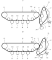
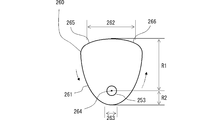
- FIG. 4A and 4B are schematic front cross-sectional views when the secondary transfer unit of the image forming apparatus is located at a separation position and a contact position. It is a schematic diagram which shows the shape of the cam which is a conversion mechanism of the image forming apparatus. It is a schematic diagram which shows the arrangement
- 6 is a flowchart showing execution processing of a density adjustment mode and an image formation mode in the image forming apparatus.
- 3 is a flowchart showing a setting process of an applied voltage in the image forming apparatus.
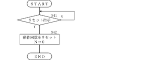
- FIG. 6 is a flowchart showing reset processing of the number of operations of the electromagnetic clutch in the image forming apparatus.
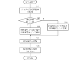
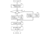
- A), (B), and (C) are schematic front sectional views of the primary transfer roller during non-image forming processing, monochrome image forming processing, and color image forming processing of the image forming apparatus. It is a flowchart which shows the setting process of the applied voltage based on the execution frequency of a job. 6 is a flowchart illustrating a setting process of an applied voltage based on the number of images that have undergone image formation processing.
- the image forming apparatus 100 includes a paper feeding unit 80, an image reading unit 90, and an image forming unit 110, and uses the image data read from the original by the image reading unit 90 from the paper feeding unit 80.
- the image forming unit 110 performs image forming processing by the electrophotographic method on the conveyed paper.
- the image forming apparatus 100 may perform an image forming process based on image data input from an external apparatus.
- the image forming unit 110 includes image forming units 10A to 10D, an intermediate transfer unit 60, a secondary transfer unit 30, and a fixing unit 70.
- the image forming units 10A to 10D respectively form black (Bk), cyan (C), magenta (M), and yellow (Y) toner images on the surfaces of the photosensitive drums 3A to 3D.
- the intermediate transfer unit 60 includes an intermediate transfer belt 61, a driving roller 62, a driven roller 63, and primary transfer rollers 64A to 64D.
- the intermediate transfer belt 61 is stretched around the driving roller 62 and the driven roller 63, and moves along a circulation path that passes through the image forming units 10D, 10C, 10B, and 10A in this order.
- Each of the primary transfer rollers 64A to 64D is disposed to face the photosensitive drums 3A to 3D with the intermediate transfer belt 61 interposed therebetween, and the toner images formed on the peripheral surfaces of the photosensitive drums 3A to 3D are intermediate transferred. Primary transfer is performed on the surface of the belt 61.
- the photosensitive drums 3A to 3D correspond to the image carrier of the present invention when the primary transfer rollers 64A to 64D are used as the transfer unit of the present invention.
- Y, M, C, and Bk toner images are sequentially transferred onto the surface of the intermediate transfer belt 61 while the intermediate transfer belt 61 moves along the circulation path.
- the monochrome image forming process only the Bk toner image is transferred to the surface of the intermediate transfer belt 61 while the intermediate transfer belt 61 moves along the circulation path.
- the secondary transfer unit 30 includes a secondary transfer roller 31 and a secondary transfer belt 32.
- the secondary transfer belt 32 is stretched around a plurality of rollers and moves along a predetermined circulation path.
- the secondary transfer roller 31 is disposed at a secondary transfer position facing the drive roller 62 with the secondary transfer belt 32 and the intermediate transfer belt 61 interposed between the secondary transfer roller 31 and the drive roller 62.
- the secondary transfer unit 30 secondarily transfers the toner image on the surface of the intermediate transfer belt 61 onto a sheet conveyed between the intermediate transfer belt 61 and the secondary transfer belt 32.
- the intermediate transfer belt 61 corresponds to the image carrier of the present invention when the secondary transfer unit 30 is the transfer unit of the present invention.
- the secondary transfer unit 30 includes a secondary transfer frame 33 in addition to the secondary transfer roller 31 and the secondary transfer belt 32.
- the secondary transfer frame 33 pivotally supports the secondary transfer roller 31 and the secondary transfer belt 32.
- one end of the spring 280 is locked, and the other end of the spring 280 is locked at a predetermined position of the main body frame of the image forming apparatus 100.
- the secondary transfer frame 33 is biased in a direction away from the intermediate transfer belt 61 by a spring 280.
- the secondary transfer frame 33 has cams (corresponding to the conversion mechanism of the present invention) 260 and 270 that are eccentric cams of the same shape on the opposite side of the intermediate transfer belt 61 and in the vicinity of both ends in the axial direction of the drive roller 62. It arrange
- the cam 260 has a contact formation portion 262 and a separation formation portion 263 on the outer peripheral portion 261, and a distance R1 from the rotation center 264 of the contact formation portion 262 is a separation formation portion 263. Is formed longer than the distance R2 from the rotation center 264.
- the cams 260 and 270 are subjected to the force of the spring 280 biased in the direction away from the intermediate transfer belt 61 in a state where the separation forming portion 263 is in contact with the secondary transfer frame 33, and the secondary transfer unit 30. Is positioned at a separation position (see FIG. 2A). The cams 260 and 270 contact the secondary transfer unit 30 when the contact forming portion 262 is in contact with the secondary transfer frame 33 and the force for pressing the intermediate transfer belt 61 is larger than the force of the spring 280. (See FIG. 2B).
- the degree of increase in the diameter when the contact point of the outer peripheral portion 261 of the cam 260 with the secondary transfer frame 33 goes from the contact formation portion 262 toward the upstream end portion 265 is determined so that the contact point is downstream from the separation formation portion 263. It is larger than the degree of increase in diameter when heading toward the side end 266. Therefore, the rotation of the contact point from the contact formation portion 262 via the upstream end portion 265 toward the separation formation portion 263 causes the contact point to contact from the separation formation portion 263 via the downstream end portion 266. It is larger than the rotation toward the formation part 262. For this reason, once the contact point is located at the contact formation part 262, the contact point moves from the contact formation part 262, and toward the separation formation part 263 via the upstream end 265 or the downstream end 266. The situation where it ends is prevented.
- the electromagnetic clutch 250 includes a rotor 251, an exciting coil 252, a clutch shaft 253 that is an output shaft, a clutch bearing 254, and an amateur 255.
- the rotor 251 is connected to a motor 256, which is a drive source, via a gear train (not shown). When the rotation of the motor 256 is supplied, the rotor 251 rotates in synchronization with the rotation of the motor 256.
- the rotor 251 has a cylindrical shape having an opening inside, and is disposed at a predetermined position of the main body frame of the image forming apparatus 100.
- An excitation coil 252 to which a voltage is applied by the power supply device 240 is disposed in the space formed in the rotor 251.
- a clutch bearing 254 that rotatably supports the clutch shaft 253 is held on the inner peripheral surface of the rotor 251.
- the clutch shaft 253 is arranged so that the axial direction thereof coincides with the axial direction of the secondary transfer roller 31.
- Cams 260 and 270 and an amateur 255 are fixed to the clutch shaft 253.
- the amateur 255 is disposed such that the suction surface 255A faces the rotor 251 and is fixed so as to be movable only in the axial direction of the clutch shaft 253.
- the excitation coil 252 When a voltage is applied to the excitation coil 252 by the power supply device 240 while the motor 256 is rotating, the excitation coil 252 is excited.
- the exciting coil 252 When the exciting coil 252 is excited, the attracting surface 255A of the armature 255 is attracted to the rotor 251 and the protrusion 255B of the attracting surface 255A is fitted into the recess 251A of the rotor 251.
- the rotation of the rotor 251 is transmitted to the clutch shaft 253 via the amateur 255.
- the cams 260 and 270 rotate.
- the secondary transfer unit 30 is brought into contact with the intermediate transfer belt 61 and the separated position separated from the intermediate transfer belt 61 (see FIG. 2A) as the cams 260 and 270 rotate.
- the cams 260 and 270 stop rotating when they are displaced with respect to the contact position (see FIG. 2B), they are located at the separated position or the contact position as they are.
- the image forming apparatus 100 further includes a reflective photosensor 300, an operation unit 130, and a control unit 200.
- the reflective photosensor 300 is disposed around the intermediate transfer belt 61 and detects the amount of light reflected from the intermediate transfer belt 61.
- the operation unit 130 inputs an execution instruction for various execution modes such as a density adjustment mode for adjusting an image density at the time of image formation processing and an image formation mode for performing an image formation process on a sheet, and an input for a reset instruction for the counter 241. And accept.
- the reflective photosensor 300 detects the reflected light amount of the test toner image formed on the intermediate transfer belt 61, thereby detecting the image density of each color and adjusting the density to an appropriate image density. Perform the adjustment process.
- the density adjustment processing is performed in a state where the secondary transfer unit 30 is positioned at a separated position away from the intermediate transfer belt 61 (see FIG. 2A).
- the density adjustment process is not limited to accepting an input of a density adjustment mode execution instruction from the operation unit 130, but may be a predetermined job for which the image forming apparatus 100 is turned on, a jam process, or a job including the image formation process. It is performed at the time of every execution.
- image forming processing such as copying and printing is performed on the paper.
- the image forming process is performed in a state where the secondary transfer unit 30 is positioned at a contact position that contacts the intermediate transfer belt 61 (see FIG. 2B).
- the control unit 200 includes an input unit 210 to which information from the operation unit 130 is input, a memory 220 that stores the position of the secondary transfer unit 30, and an electromagnetic clutch that can selectively block transmission of rotation to the cams 260 and 270. 250, a power supply device 240 that applies a voltage to the electromagnetic clutch 250, and a CPU 230 that instructs the power supply device 240 to apply a voltage.
- the power supply apparatus 240 includes a counter 241 that counts the number of operations of the electromagnetic clutch 250, a CPU 242 that determines an applied voltage to the electromagnetic clutch 250, and a power supply 243 that supplies power at a voltage lower than the rated voltage and higher than the rated voltage.
- the power supply device 240 may include only the power supply 243 and may be controlled by the CPU 230.
- the control unit 200 includes a counter 241.
- the CPU 230 when the execution instruction of the density adjustment mode is input (S11), the CPU 230 refers to the memory 220 and acquires the position of the secondary transfer unit 30 (S12). When the secondary transfer unit 30 is located at the separation position (S13), the CPU 230 performs density adjustment processing (S16).
- the CPU 230 When the secondary transfer unit 30 is not located at the separation position but is located at the contact position, the CPU 230 performs the displacement processing shown in FIG. 7 by the CPU 242 so as to displace the secondary transfer unit 30 to the separation position. Perform (S14).
- the CPU 242 refers to the count value of the counter 241 and obtains the operation frequency N of the electromagnetic clutch 250 (S31).
- the CPU 242 sets a voltage (26V, 28V, etc.) higher than the rated voltage (24V) as an applied voltage when the number of operations N is a predetermined number (for example, 20 times, 30 times, etc.) M or less (S32).
- a voltage equal to or lower than the rated voltage (24V) is set as the applied voltage (S34).
- the predetermined number of times M is the number of operations of the electromagnetic clutch 250 in which the suction surface 255A of the armature 255 of the electromagnetic clutch 250 is sufficiently smoothed and the friction coefficient of the suction surface 255A is equal to or greater than a predetermined value.
- the CPU 242 applies the set applied voltage to the electromagnetic clutch 250 for a predetermined time T (S35).
- the predetermined time T is a time for which the secondary transfer unit 30 is displaced from the contact position to the separation position.
- the CPU 242 updates the count value of the counter 241 indicating the number of operations N of the electromagnetic clutch 250 to N + 1 (S36).
- the CPU 230 updates the position of the secondary transfer unit 30 stored in the memory 220 to a separated position (S15), and performs density adjustment processing (S16).
- the CPU 230 refers to the memory 220 and acquires the position of the secondary transfer unit 30 (S17). When the secondary transfer unit 30 is located at the contact position (S18), the CPU 230 performs an image forming process (S21).
- the CPU 230 When the secondary transfer unit 30 is not positioned at the contact position but positioned at the separation position, the CPU 230 performs the displacement process shown in FIG. 7 so that the secondary transfer unit 30 is displaced to the contact position. (S19). The CPU 230 updates the position of the secondary transfer unit 30 stored in the memory 220 to the contact position (S20), and performs image forming processing (S21).
- the CPU 230 applies a voltage higher than the rated voltage because the attracting surface 255A of the armature 255 is not sufficiently smoothed and the friction coefficient is low. Set as voltage.
- the electromagnetic clutch 250 is used a predetermined number of times M, the attracting surface 255A of the armature 255 is sufficiently smoothed and the friction coefficient is high, so a voltage equal to or lower than the rated voltage is set as the applied voltage.
- the electromagnetic clutch 250 can reliably transmit the rotation of the motor 256 to the cams 260 and 270 even in the initial stage of use.
- a large force is required for the displacement of the secondary transfer unit 30 to the contact position and the separation position.
- the rotation of the motor 256 can be reliably transmitted to the cams 260 and 270, so that the secondary transfer unit 30 can be reliably displaced to the contact position and the separation position.
- the CPU 230 waits for input of a reset instruction (S41).
- the CPU 242 resets the count value of the counter 241 indicating the number of operations N of the electromagnetic clutch 250 (S42).
- each of the primary transfer rollers 64B to 64D is in a contact position where the primary transfer roller 64A contacts the photosensitive drum 3A with the intermediate transfer belt 61 interposed therebetween.
- the cam 260 displaces the photosensitive drums 3B to 3D to separate positions separated from each other.
- each of the primary transfer rollers 64A to 64D is in contact with the photosensitive drums 3A to 3D with the intermediate transfer belt 61 interposed therebetween. Is displaced by. Since displacement of the primary transfer rollers 64A to 84D to the contact position and the separation position requires a large force, a configuration for controlling the voltage to the electromagnetic clutch 250 that transmits the rotation to the cam 260 may be used. Accordingly, even when the electromagnetic clutch 250 is used, the rotation of the motor 256 can be reliably transmitted to the cam 260, so that the primary transfer rollers 64A to 84D can be reliably displaced to the contact position and the separation position. it can.
- a configuration for controlling the voltage to the electromagnetic clutch 250 that transmits the rotation to the various rollers may be used.
- the image forming apparatus 100 may set the applied voltage according to the number of executions of the image forming job.
- the control unit 200 applies a voltage higher than the rated voltage to the electromagnetic clutch 250 (S33), and executes the image forming job.
- the number of times NA exceeds the predetermined number of times MA, a voltage equal to or lower than the rated voltage is applied to the electromagnetic clutch 250 (S34). Accordingly, it is not necessary to provide the counter 241 for counting the number of operations of the electromagnetic clutch 250, and the voltage applied to the electromagnetic clutch 250 can be controlled using an existing counter for counting the number of executions of the image forming job.
- the applied voltage may be set according to the number of sheets on which image forming processing has been performed.
- the control unit 200 applies a voltage higher than the rated voltage to the electromagnetic clutch 250 (S33) when the number of sheets NB on which image forming processing has been performed is equal to or less than the predetermined number MB (S52).
- a voltage equal to or lower than the rated voltage is applied to the electromagnetic clutch 250 (S34).
Landscapes
- Physics & Mathematics (AREA)
- General Physics & Mathematics (AREA)
- Engineering & Computer Science (AREA)
- General Engineering & Computer Science (AREA)
- Electromagnetism (AREA)
- Fluid Mechanics (AREA)
- Mechanical Engineering (AREA)
- Microelectronics & Electronic Packaging (AREA)
- Electrostatic Charge, Transfer And Separation In Electrography (AREA)
- Hydraulic Clutches, Magnetic Clutches, Fluid Clutches, And Fluid Joints (AREA)
Abstract
使用の初期においても、回転を確実に伝達することができるようにする。CPU(242)は、印加電圧の設定処理を行う(S14)。CPU(242)は、電磁クラッチ250の動作回数Nを取得し(S31)、動作回数Nが所定の回数M以下の場合に(S32)、定格電圧より高い電圧(26V,28V等)を印加電圧として設定し(S33)、動作回数Nが所定の回数Mを超える場合に、定格電圧以下の電圧を印加電圧として設定する(S34)。所定の回数Mは、アマチュア(255)の吸着面(255A)が十分に平滑化されて、摩擦係数が所定値以上となる電磁クラッチ(250)の動作回数である。CPU(242)は、設定した印加電圧を所定時間(T)の間、電磁クラッチ(250)に印加する(S15)。
Description
この発明は、電磁クラッチへ電圧を印加する電源供給装置、及び電磁クラッチと電源供給装置とを備える画像形成装置に関する。
電磁クラッチは、励磁コイル、ロータ、及びアマチュアを備え、入力軸の回転を出力軸に伝達する。励磁コイルは、電源供給装置から電圧の印加を選択的に受ける。ロータは、入力軸に連結されており、入力軸とともに回転する。アマチュアは、出力軸に連結されており、励磁コイルへの電圧の印加時に、吸着面をロータに密着させてロータの回転を出力軸に伝達する。なお、電磁クラッチには、励磁コイルへの電圧の非印加時に、アマチュアの吸着面をロータに密着させるものもある。
励磁コイルに電圧を印加する電源供給装置には、電磁クラッチの応答性を向上させるとともに電力消費量を低減するために、印加する電圧を変更するものがある(例えば、特許文献1参照。)。特許文献1に記載の電源供給装置は、印加開始時に定格電圧の2~4倍の電圧を一定時間印加した後に、定格電圧以下の電圧に切り換えて印加する。
電磁クラッチの使用の初期において、アマチュアの吸着面は、十分に平滑化されずに、摩擦係数が低い状態であることが多い。この状態で、励磁コイルに定格電圧以下の電圧を印加すると、アマチュアの吸着面とロータとの間に滑りを生じ、入力軸の回転を出力軸に確実に伝達することができない。
例えば、電子写真方式の画像形成装置には、転写ユニットを複数の位置の間で変位させる機構の一部に電磁クラッチを備えたものがある。転写ユニットを複数の位置の間で変位させるためには大きな力を必要とし、電磁クラッチ内で入力軸の回転が出力軸に確実に伝達されないと、転写ユニットを正確に変位させることができない。
そこで、この発明の目的は、電磁クラッチの使用の初期においても、入力軸の回転を出力軸に確実に伝達することができる電源供給装置、及び電源供給装置を備えた画像形成装置を提供することにある。
この発明の電源供給装置は、カウンタ及び制御部を備える。カウンタは、電磁クラッチの動作回数をカウントする。制御部は、カウンタがカウントした動作回数が所定の回数以下の場合に、定格電圧よりも高い電圧を電磁クラッチに印加する。定格電圧は、電磁クラッチに印加される電圧の基準値である。この構成では、電磁クラッチは、使用の初期において、アマチュアの吸着面が十分に平滑化されずに摩擦係数が低い状態であるため、定格電圧よりも高い電圧が印加される。
この発明の電源供給装置、及び画像形成装置は、電圧を印加する電磁クラッチの使用の初期においても、当該電磁クラッチを介して回転を確実に伝達することができる。
図1に示すように、画像形成装置100は、給紙部80、画像読取部90及び画像形成部110を備え、画像読取部90で原稿から読み取った画像データを用いて、給紙部80から搬送した用紙に、画像形成部110で電子写真方式による画像形成処理を行う。画像形成装置100は、外部装置から入力される画像データに基づく画像形成処理を行うものであってもよい。
画像形成部110は、画像形成ユニット10A~10D、中間転写ユニット60、二次転写ユニット30、定着ユニット70を備えている。
画像形成ユニット10A~10Dは、それぞれ感光体ドラム3A~3Dの表面にブラック(Bk)、シアン(C)、マゼンダ(M)、イエロー(Y)のトナー像を形成する。
中間転写ユニット60は、中間転写ベルト61、駆動ローラ62、従動ローラ63、一次転写ローラ64A~64Dを有する。中間転写ベルト61は、駆動ローラ62、及び従動ローラ63に張架され、画像形成ユニット10D、10C、10B、10Aをこの順に通過する循環経路に沿って移動する。一次転写ローラ64A~64Dのそれぞれは、中間転写ベルト61を挟んで感光体ドラム3A~3Dに対向して配置されており、感光体ドラム3A~3Dの周面に形成されたトナー像を中間転写ベルト61の表面に一次転写する。
感光体ドラム3A~3Dは、一次転写ローラ64A~64Dを本発明の転写ユニットとした場合に、本発明の像担持体に相当する。
カラー画像形成処理時には、中間転写ベルト61が循環経路に沿って移動する間に、Y,M,C,Bkのトナー像が中間転写ベルト61の表面に順次重ね合わせて転写される。モノクロ画像形成処理時には、中間転写ベルト61が循環経路に沿って移動する間に、Bkのトナー像のみが中間転写ベルト61の表面に転写される。
二次転写ユニット30は、二次転写ローラ31及び二次転写ベルト32を備えている。二次転写ベルト32は、複数のローラに張架され、所定の循環経路に沿って移動する。二次転写ローラ31は、駆動ローラ62との間に二次転写ベルト32及び中間転写ベルト61を挟んで駆動ローラ62に対向する二次転写位置に配置されている。二次転写ユニット30は、中間転写ベルト61の表面のトナー像を、中間転写ベルト61と二次転写ベルト32との間に搬送された用紙へ二次転写する。
中間転写ベルト61は、二次転写ユニット30を本発明の転写ユニットとした場合に、本発明の像担持体に相当する。
図2に示すように、二次転写ユニット30は、二次転写ローラ31及び二次転写ベルト32の他に二次転写フレーム33を備える。二次転写フレーム33は、二次転写ローラ31及び二次転写ベルト32を軸支する。二次転写フレーム33は、バネ280の一端部が係止され、バネ280の他端部は、画像形成装置100の本体フレームの所定位置に係止されている。二次転写フレーム33は、バネ280によって中間転写ベルト61から離間する方向へ付勢されている。
二次転写フレーム33は、中間転写ベルト61の反対側で且つ駆動ローラ62の軸方向における両端付近に、同一形状の偏心カムであるカム(本発明の変換機構に相当する。)260,270が当接するように配置されている。図3に示すように、カム260は、外周部261に当接形成部262及び離間形成部263を有しており、当接形成部262の回転中心264からの距離R1が、離間形成部263の回転中心264からの距離R2よりも長く形成されている。
カム260,270は、離間形成部263が二次転写フレーム33に当接した状態で、中間転写ベルト61から離間する方向に付勢されたバネ280の力が作用して、二次転写ユニット30を離間位置に位置させる(図2(A)参照。)。カム260,270は、当接形成部262が二次転写フレーム33に当接した状態で、中間転写ベルト61を圧接する力がバネ280の力よりも大きくなり、二次転写ユニット30を当接位置に位置させる(図2(B)参照。)。
また、カム260の外周部261における二次転写フレーム33との当接点が、当接形成部262から上流側端部265へ向かう際の径の増加度合いは、当接点が離間形成部263から下流側端部266へ向かう際の径の増加度合いよりも大きい。よって、当接点が当接形成部262から上流側端部265を経由して離間形成部263へ向かう際の回転は、当接点が離間形成部263から下流側端部266を経由して当接形成部262へ向かう際の回転よりも大きい。このため、一旦当接点が当接形成部262に位置すると、当接点が当接形成部262から移動し、上流側端部265又は下流側端部266を経由して離間形成部263に向かってしまうという事態が防止される。
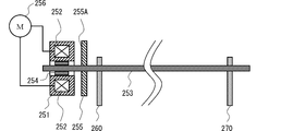
図4に示すように、電磁クラッチ250は、ロータ251、励磁コイル252、出力軸であるクラッチ軸253、クラッチ軸受254、及びアマチュア255を備えている。
ロータ251は、駆動源であるモータ256にギアトレイン(不図示)を介して連結されており、モータ256の回転が供給されるとモータ256の回転に同期して回転する。ロータ251は、内部に開口を有する円柱状を呈し、画像形成装置100の本体フレームの所定位置に配設されている。ロータ251に形成された空間部には、電源供給装置240によって電圧が印加される励磁コイル252が配置されている。ロータ251の内周面には、クラッチ軸253を回転自在に支持するクラッチ軸受254が保持されている。
クラッチ軸253は、軸方向が二次転写ローラ31の軸方向に一致するように配置されている。クラッチ軸253は、カム260,270、及びアマチュア255が固定されている。アマチュア255は、吸着面255Aがロータ251に対向するように配置され、且つクラッチ軸253の軸方向にのみ移動自在に固定されている。
モータ256の回転中に、電源供給装置240によって励磁コイル252に電圧を印加すると、励磁コイル252が励磁する。励磁コイル252が励磁すると、アマチュア255の吸着面255Aがロータ251に吸着し、吸着面255Aの突起部255Bがロータ251の凹部251Aに嵌合する。ロータ251の回転は、アマチュア255を介してクラッチ軸253に伝達する。クラッチ軸253の回転に伴って、カム260,270が回転する。
この状態で、電源供給装置240による電圧の印加を止めると、アマチュア255の吸着面255Aがロータ251から離脱して、クラッチ軸253への回転の伝達を遮断する。クラッチ軸253の回転の停止に伴って、カム260,270は回転を停止する。
以上のように、二次転写ユニット30は、カム260,270の回転に伴って、中間転写ベルト61から離間した離間位置(図2(A)参照。)と、中間転写ベルト61に当接する当接位置(図2(B)参照。)との間で変位し、カム260,270の回転が停止すると、離間位置又は当接位置にそのまま位置する。
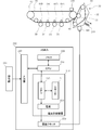
図5に示すように、画像形成装置100は、反射型フォトセンサ300、操作部130及び制御部200をさらに備える。反射型フォトセンサ300は、中間転写ベルト61の周囲に配置され、中間転写ベルト61からの反射光量を検知する。
操作部130は、画像形成処理時の画像濃度の調整を行う濃度調整モード、及び用紙に対する画像形成処理を行う画像形成モード等の各種実行モードの実行指示の入力と、カウンタ241のリセット指示の入力とを受け付ける。
濃度調整モードでは、中間転写ベルト61に形成されたテスト用のトナー像の反射光量を反射型フォトセンサ300が検知することで、各色の画像濃度を検出して、適正な画像濃度に調整する濃度調整処理を行う。濃度調整処理は、中間転写ベルト61から離れる離間位置に二次転写ユニット30を位置させた状態(図2(A)参照。)で行われる。また、濃度調整処理は、操作部130による濃度調整モードの実行指示の入力受付時の他に、画像形成装置100の主電源投入時、ジャム処理時や、画像形成処理を内容とするジョブの所定回数毎の実行時に行われる。
画像形成モードでは、コピーや印刷等の画像形成処理を用紙に対して行う。画像形成処理は、中間転写ベルト61に当接する当接位置に二次転写ユニット30を位置させた状態(図2(B)参照。)で行われる。
制御部200は、操作部130からの情報が入力される入力部210、二次転写ユニット30の位置を記憶するメモリ220、カム260,270への回転の伝達を選択的に遮断可能な電磁クラッチ250、電磁クラッチ250に電圧を印加する電源供給装置240、及び電源供給装置240に対して電圧の印加を指示するCPU230を備える。
電源供給装置240は、電磁クラッチ250の動作回数をカウントするカウンタ241、電磁クラッチ250への印加電圧を決定するCPU242、定格電圧以下の電圧及び定格電圧より高い電圧で電力を供給する電源243を備える。なお、電源供給装置240は、電源243のみを備え、CPU230によって制御してもよい。この場合、制御部200は、カウンタ241を備える。
図6に示すように、CPU230は、濃度調整モードの実行指示が入力されると(S11)、メモリ220を参照して二次転写ユニット30の位置を取得する(S12)。CPU230は、二次転写ユニット30が離間位置に位置する場合に(S13)、濃度調整処理を行う(S16)。
CPU230は、二次転写ユニット30が離間位置に位置せずに、当接位置に位置する場合には、二次転写ユニット30を離間位置に変位させるように、図7に示す変位処理をCPU242によって行う(S14)。
図7に示すように、CPU242は、カウンタ241のカウント値を参照して電磁クラッチ250の動作回数Nを取得する(S31)。CPU242は、動作回数Nが所定の回数(例えば、20回、30回等)M以下の場合に(S32)、定格電圧(24V)より高い電圧(26V,28V等)を印加電圧として設定し(S33)、動作回数Nが所定の回数Mを超える場合には、定格電圧(24V)以下の電圧を印加電圧として設定する(S34)。所定の回数Mは、電磁クラッチ250のアマチュア255の吸着面255Aが十分に平滑化されて、吸着面255Aの摩擦係数が所定値以上になる電磁クラッチ250の動作回数である。CPU242は、設定した印加電圧を所定時間Tの間、電磁クラッチ250に印加する(S35)。所定時間Tは、二次転写ユニット30が当接位置から離間位置へ変位する時間である。CPU242は、電磁クラッチ250の動作回数Nを示すカウンタ241のカウント値をN+1に更新する(S36)。
CPU230は、メモリ220に記憶している二次転写ユニット30の位置を離間位置に更新して(S15)、濃度調整処理を行う(S16)。
また、CPU230は、画像形成モードの実行指示が入力された場合には、メモリ220を参照して二次転写ユニット30の位置を取得する(S17)。CPU230は、二次転写ユニット30が当接位置に位置する場合に(S18)、画像形成処理を行う(S21)。
CPU230は、二次転写ユニット30が当接位置に位置せずに、離間位置に位置する場合には、二次転写ユニット30を当接位置に変位させるように、図7に示す変位処理をCPU242によって行う(S19)。CPU230は、メモリ220に記憶している二次転写ユニット30の位置を当接位置に更新して(S20)、画像形成処理を行う(S21)。
以上のように、CPU230は、電磁クラッチ250の使用の初期においては、アマチュア255の吸着面255Aが十分に平滑化されずに、摩擦係数が低い状態であるため、定格電圧よりも高い電圧を印加電圧として設定する。電磁クラッチ250の所定の回数Mの使用後においては、アマチュア255の吸着面255Aが十分に平滑化されて、摩擦係数が高い状態であるため、定格電圧以下の電圧を印加電圧として設定する。
これにより、電磁クラッチ250は、使用の初期においても、モータ256の回転を確実にカム260,270へ伝達することができる。特に、二次転写ユニット30の当接位置及び離間位置への変位には大きな力を要する。電磁クラッチ250の使用の初期においても、モータ256の回転を確実にカム260,270へ伝達することができるため、二次転写ユニット30を当接位置及び離間位置へ確実に変位させることができる。
また、CPU230は、図8に示すように、リセット指示の入力を待機する(S41)。CPU230は、リセット指示の入力を受け付けると、電磁クラッチ250の動作回数Nを示すカウンタ241のカウント値をCPU242によってリセットする(S42)。
これにより、アマチュア255の吸着面255Aが十分に平滑化されていない電磁クラッチ250に交換したとしても、電磁クラッチ250の交換時にカウンタをリセットすることで、モータ256の回転を確実にカム260,270へ伝達することができる。
また、図9(A)に示すように、非画像形成処理時において、一次転写ローラ64A~64Dのそれぞれが感光体ドラム3A~3Dのそれぞれから離間する離間位置にカム260によって変位する。図9(B)に示すように、モノクロ画像形成処理時において、一次転写ローラ64Aが中間転写ベルト61を挟んで感光体ドラム3Aに当接する当接位置に、一次転写ローラ64B~64Dのそれぞれが感光体ドラム3B~3Dのそれぞれから離間する離間位置にカム260によって変位する。図9(C)に示すように、カラー画像形成処理時において、一次転写ローラ64A~64Dのそれぞれが中間転写ベルト61を挟んで感光体ドラム3A~3Dのそれぞれに当接する当接位置にカム260によって変位する。一次転写ローラ64A~84Dの当接位置及び離間位置への変位についても、大きな力を要するため、カム260へ回転を伝達する電磁クラッチ250への電圧を制御する構成を用いればよい。これにより、電磁クラッチ250の使用の初期においても、モータ256の回転を確実にカム260に伝達することができるため、一次転写ローラ64A~84Dを当接位置及び離間位置へ確実に変位させることができる。
さらに、用紙搬送路40上に配置された各種ローラの回転についても、各種ローラへ回転を伝達する電磁クラッチ250への電圧を制御する構成を用いてもよい。
また、画像形成装置100は、図10に示すように、画像形成ジョブの実行回数に応じて印加電圧を設定してもよい。この場合、制御部200は、画像形成ジョブの実行回数NAが所定の回数MA以下の場合に(S42)、定格電圧より高い電圧を電磁クラッチ250に印加して(S33)、画像形成ジョブの実行回数NAが所定の回数MAを超えた場合に、定格電圧以下の電圧を電磁クラッチ250に印加する(S34)。これにより、電磁クラッチ250の動作回数をカウントするカウンタ241を備える必要がなく、画像形成ジョブの実行回数をカウントする既設のカウンタを用いて電磁クラッチ250に印加する電圧を制御することができる。
また、図11に示すように、画像形成処理が行われた用紙の枚数に応じて印加電圧を設定してもよい。この場合、制御部200は、画像形成処理が行われた用紙の枚数NBが所定の枚数MB以下の場合に(S52)、定格電圧より高い電圧を電磁クラッチ250に印加して(S33)、画像形成処理が行われた用紙の枚数NBが所定の枚数MBを超えた場合に、定格電圧以下の電圧を電磁クラッチ250に印加する(S34)。これにより、電磁クラッチ250の動作回数をカウントするカウンタ241を備える必要がなく、画像形成処理が行われた用紙の枚数をカウントする既設のカウンタを用いて電磁クラッチ250に印加する電圧を制御することができる。
上述の実施形態の説明は、すべての点で例示であって、制限的なものではないと考えられるべきである。本発明の範囲は、上述の実施形態ではなく、特許請求の範囲によって示される。さらに、本発明の範囲には、特許請求の範囲と均等の意味及び範囲内でのすべての変更が含まれることが意図される。
30…二次転写ユニット
64A~64D…一次転写ローラ
100…画像形成装置
110…画像形成部
200…制御部
210…入力部
220…メモリ
230…CPU
240…電源供給装置
241…カウンタ
242…CPU
243…電源
250…電磁クラッチ
260,270…カム
64A~64D…一次転写ローラ
100…画像形成装置
110…画像形成部
200…制御部
210…入力部
220…メモリ
230…CPU
240…電源供給装置
241…カウンタ
242…CPU
243…電源
250…電磁クラッチ
260,270…カム
Claims (4)
- 電磁クラッチの動作回数をカウントするカウンタと、
前記カウンタがカウントした前記動作回数が所定の回数以下の場合に、前記電磁クラッチに印加される電圧の基準値である定格電圧よりも高い電圧を前記電磁クラッチに印加する制御部と、を備える電源供給装置。 - 前記制御部は、前記カウンタがカウントした前記動作回数が前記所定の回数を超えると、前記定格電圧以下の電圧を前記電磁クラッチに印加する請求項1に記載の電源供給装置。
- 前記制御部は、前記電磁クラッチの交換時に、前記カウンタがカウントする前記動作回数をリセットする請求項1に記載の電源供給装置。
- 像担持体上の静電潜像を顕像化してトナー像を形成する現像ユニットと、前記トナー像を用紙に転写する転写ユニットとを有し、前記用紙に電子写真方式の画像形成処理を行う画像形成装置であって、
駆動源の回転の伝達を選択的に遮断可能な電磁クラッチと、
前記電磁クラッチへ電圧を印加する、請求項1に記載の電源供給装置と、
前記電磁クラッチを介して伝達された回転を、前記転写ユニットを複数の位置の何れかの位置から他の位置へ変位するための駆動力に変換する変換機構と、を備える画像形成装置。
Applications Claiming Priority (2)
| Application Number | Priority Date | Filing Date | Title |
|---|---|---|---|
| JP2011-136451 | 2011-06-20 | ||
| JP2011136451A JP2013003456A (ja) | 2011-06-20 | 2011-06-20 | 画像形成装置 |
Publications (1)
| Publication Number | Publication Date |
|---|---|
| WO2012176691A1 true WO2012176691A1 (ja) | 2012-12-27 |
Family
ID=47422529
Family Applications (1)
| Application Number | Title | Priority Date | Filing Date |
|---|---|---|---|
| PCT/JP2012/065301 Ceased WO2012176691A1 (ja) | 2011-06-20 | 2012-06-15 | 電磁クラッチの電源供給装置及び画像形成装置 |
Country Status (2)
| Country | Link |
|---|---|
| JP (1) | JP2013003456A (ja) |
| WO (1) | WO2012176691A1 (ja) |
Citations (3)
| Publication number | Priority date | Publication date | Assignee | Title |
|---|---|---|---|---|
| JPH01279271A (ja) * | 1988-05-02 | 1989-11-09 | Fuji Xerox Co Ltd | 電流値セットアップ機能を備えた記録装置 |
| JP2008309275A (ja) * | 2007-06-15 | 2008-12-25 | Calsonic Kansei Corp | 電磁クラッチ制御装置 |
| JP2009041713A (ja) * | 2007-08-10 | 2009-02-26 | Nissan Motor Co Ltd | 車両空調用クラッチ制御装置 |
Family Cites Families (3)
| Publication number | Priority date | Publication date | Assignee | Title |
|---|---|---|---|---|
| JPH0887153A (ja) * | 1994-09-20 | 1996-04-02 | Fuji Xerox Co Ltd | カラー画像形成装置の回転トルク接断装置 |
| JP2006227660A (ja) * | 2006-06-02 | 2006-08-31 | Seiko Epson Corp | 画像形成ユニットの離当接タイミング調整装置 |
| JP4551941B2 (ja) * | 2008-03-03 | 2010-09-29 | シャープ株式会社 | 画像形成装置 |
-
2011
- 2011-06-20 JP JP2011136451A patent/JP2013003456A/ja active Pending
-
2012
- 2012-06-15 WO PCT/JP2012/065301 patent/WO2012176691A1/ja not_active Ceased
Patent Citations (3)
| Publication number | Priority date | Publication date | Assignee | Title |
|---|---|---|---|---|
| JPH01279271A (ja) * | 1988-05-02 | 1989-11-09 | Fuji Xerox Co Ltd | 電流値セットアップ機能を備えた記録装置 |
| JP2008309275A (ja) * | 2007-06-15 | 2008-12-25 | Calsonic Kansei Corp | 電磁クラッチ制御装置 |
| JP2009041713A (ja) * | 2007-08-10 | 2009-02-26 | Nissan Motor Co Ltd | 車両空調用クラッチ制御装置 |
Also Published As
| Publication number | Publication date |
|---|---|
| JP2013003456A (ja) | 2013-01-07 |
Similar Documents
| Publication | Publication Date | Title |
|---|---|---|
| JP3884960B2 (ja) | 駆動装置及びカラー画像形成装置 | |
| JP4932347B2 (ja) | 転写装置及び画像形成装置 | |
| US20230061068A1 (en) | Biasing force adjusting device, transfer device, and image forming apparatus | |
| US9388000B2 (en) | Spacing mechanism for spacing two members, and a fixing device sheet feeding-conveying device and image forming apparatus incorporating same | |
| JP5448245B2 (ja) | シート材排出装置及び画像形成装置 | |
| JP2015196594A (ja) | 画像形成装置 | |
| US9139391B2 (en) | Sheet conveyor, image forming apparatus incorporating same, and method of preventing sheet skew | |
| JP2017007761A (ja) | 画像形成装置、画像形成方法、及び、プログラム | |
| JP5983957B2 (ja) | 定着装置及び画像形成装置 | |
| WO2012176691A1 (ja) | 電磁クラッチの電源供給装置及び画像形成装置 | |
| JP5919648B2 (ja) | シート排出駆動装置および画像形成装置 | |
| JP2011099896A (ja) | 画像形成装置 | |
| EP2037332A2 (en) | Image forming apparatus | |
| WO2012141062A1 (ja) | 二次転写ユニットの変位機構 | |
| JP2014109332A (ja) | 駆動制御装置、画像形成装置 | |
| JP2016057514A (ja) | 転写装置およびそれを備える画像形成装置 | |
| JP2017016072A (ja) | 画像形成装置 | |
| US10209660B2 (en) | Image formation device with toner increase mode | |
| JP2002351230A (ja) | 転写装置および画像形成装置 | |
| US9725258B2 (en) | Image forming device | |
| JP2007102009A (ja) | 画像形成装置及び制御方法 | |
| JP2007309954A (ja) | 回転カム機構及びこれを備える画像形成装置 | |
| JP6512409B2 (ja) | 定着装置及び該定着装置を備えた画像形成装置 | |
| JP2012088748A (ja) | 画像形成装置及び制御方法 | |
| US10259672B2 (en) | Image forming apparatus and sheet conveying unit |
Legal Events
| Date | Code | Title | Description |
|---|---|---|---|
| 121 | Ep: the epo has been informed by wipo that ep was designated in this application |
Ref document number: 12803115 Country of ref document: EP Kind code of ref document: A1 |
|
| NENP | Non-entry into the national phase |
Ref country code: DE |
|
| 122 | Ep: pct application non-entry in european phase |
Ref document number: 12803115 Country of ref document: EP Kind code of ref document: A1 |