WO2012176294A1 - Remote monitoring device, power generation system, and remote monitoring device control method - Google Patents
Remote monitoring device, power generation system, and remote monitoring device control method Download PDFInfo
- Publication number
- WO2012176294A1 WO2012176294A1 PCT/JP2011/064295 JP2011064295W WO2012176294A1 WO 2012176294 A1 WO2012176294 A1 WO 2012176294A1 JP 2011064295 W JP2011064295 W JP 2011064295W WO 2012176294 A1 WO2012176294 A1 WO 2012176294A1
- Authority
- WO
- WIPO (PCT)
- Prior art keywords
- switching hub
- switching
- information processing
- remote
- wind power
- Prior art date
Links
- 238000000034 method Methods 0.000 title claims description 47
- 238000010248 power generation Methods 0.000 title claims description 37
- 238000012806 monitoring device Methods 0.000 title claims description 30
- 230000005540 biological transmission Effects 0.000 claims abstract description 46
- 230000010365 information processing Effects 0.000 claims description 50
- 238000004891 communication Methods 0.000 claims description 37
- 238000012544 monitoring process Methods 0.000 claims description 19
- 238000012423 maintenance Methods 0.000 description 95
- 230000005856 abnormality Effects 0.000 description 34
- 230000008569 process Effects 0.000 description 31
- 230000007257 malfunction Effects 0.000 description 14
- 238000012545 processing Methods 0.000 description 8
- 238000004092 self-diagnosis Methods 0.000 description 8
- 230000003287 optical effect Effects 0.000 description 6
- 238000010586 diagram Methods 0.000 description 4
- 230000008439 repair process Effects 0.000 description 4
- 230000004044 response Effects 0.000 description 4
- 238000012546 transfer Methods 0.000 description 4
- 230000008859 change Effects 0.000 description 3
- 238000001816 cooling Methods 0.000 description 3
- 241000590918 Scada Species 0.000 description 1
- 238000006243 chemical reaction Methods 0.000 description 1
- 230000010485 coping Effects 0.000 description 1
- 230000000694 effects Effects 0.000 description 1
- 238000009434 installation Methods 0.000 description 1
- 238000011084 recovery Methods 0.000 description 1
Images


Classifications
-
- F—MECHANICAL ENGINEERING; LIGHTING; HEATING; WEAPONS; BLASTING
- F03—MACHINES OR ENGINES FOR LIQUIDS; WIND, SPRING, OR WEIGHT MOTORS; PRODUCING MECHANICAL POWER OR A REACTIVE PROPULSIVE THRUST, NOT OTHERWISE PROVIDED FOR
- F03D—WIND MOTORS
- F03D7/00—Controlling wind motors
-
- H—ELECTRICITY
- H04—ELECTRIC COMMUNICATION TECHNIQUE
- H04L—TRANSMISSION OF DIGITAL INFORMATION, e.g. TELEGRAPHIC COMMUNICATION
- H04L41/00—Arrangements for maintenance, administration or management of data switching networks, e.g. of packet switching networks
- H04L41/04—Network management architectures or arrangements
-
- F—MECHANICAL ENGINEERING; LIGHTING; HEATING; WEAPONS; BLASTING
- F03—MACHINES OR ENGINES FOR LIQUIDS; WIND, SPRING, OR WEIGHT MOTORS; PRODUCING MECHANICAL POWER OR A REACTIVE PROPULSIVE THRUST, NOT OTHERWISE PROVIDED FOR
- F03D—WIND MOTORS
- F03D17/00—Monitoring or testing of wind motors, e.g. diagnostics
-
- F—MECHANICAL ENGINEERING; LIGHTING; HEATING; WEAPONS; BLASTING
- F03—MACHINES OR ENGINES FOR LIQUIDS; WIND, SPRING, OR WEIGHT MOTORS; PRODUCING MECHANICAL POWER OR A REACTIVE PROPULSIVE THRUST, NOT OTHERWISE PROVIDED FOR
- F03D—WIND MOTORS
- F03D7/00—Controlling wind motors
- F03D7/02—Controlling wind motors the wind motors having rotation axis substantially parallel to the air flow entering the rotor
- F03D7/04—Automatic control; Regulation
-
- H—ELECTRICITY
- H02—GENERATION; CONVERSION OR DISTRIBUTION OF ELECTRIC POWER
- H02J—CIRCUIT ARRANGEMENTS OR SYSTEMS FOR SUPPLYING OR DISTRIBUTING ELECTRIC POWER; SYSTEMS FOR STORING ELECTRIC ENERGY
- H02J13/00—Circuit arrangements for providing remote indication of network conditions, e.g. an instantaneous record of the open or closed condition of each circuitbreaker in the network; Circuit arrangements for providing remote control of switching means in a power distribution network, e.g. switching in and out of current consumers by using a pulse code signal carried by the network
- H02J13/00001—Circuit arrangements for providing remote indication of network conditions, e.g. an instantaneous record of the open or closed condition of each circuitbreaker in the network; Circuit arrangements for providing remote control of switching means in a power distribution network, e.g. switching in and out of current consumers by using a pulse code signal carried by the network characterised by the display of information or by user interaction, e.g. supervisory control and data acquisition systems [SCADA] or graphical user interfaces [GUI]
-
- H—ELECTRICITY
- H02—GENERATION; CONVERSION OR DISTRIBUTION OF ELECTRIC POWER
- H02J—CIRCUIT ARRANGEMENTS OR SYSTEMS FOR SUPPLYING OR DISTRIBUTING ELECTRIC POWER; SYSTEMS FOR STORING ELECTRIC ENERGY
- H02J13/00—Circuit arrangements for providing remote indication of network conditions, e.g. an instantaneous record of the open or closed condition of each circuitbreaker in the network; Circuit arrangements for providing remote control of switching means in a power distribution network, e.g. switching in and out of current consumers by using a pulse code signal carried by the network
- H02J13/00006—Circuit arrangements for providing remote indication of network conditions, e.g. an instantaneous record of the open or closed condition of each circuitbreaker in the network; Circuit arrangements for providing remote control of switching means in a power distribution network, e.g. switching in and out of current consumers by using a pulse code signal carried by the network characterised by information or instructions transport means between the monitoring, controlling or managing units and monitored, controlled or operated power network element or electrical equipment
-
- H—ELECTRICITY
- H02—GENERATION; CONVERSION OR DISTRIBUTION OF ELECTRIC POWER
- H02J—CIRCUIT ARRANGEMENTS OR SYSTEMS FOR SUPPLYING OR DISTRIBUTING ELECTRIC POWER; SYSTEMS FOR STORING ELECTRIC ENERGY
- H02J13/00—Circuit arrangements for providing remote indication of network conditions, e.g. an instantaneous record of the open or closed condition of each circuitbreaker in the network; Circuit arrangements for providing remote control of switching means in a power distribution network, e.g. switching in and out of current consumers by using a pulse code signal carried by the network
- H02J13/00032—Systems characterised by the controlled or operated power network elements or equipment, the power network elements or equipment not otherwise provided for
- H02J13/00034—Systems characterised by the controlled or operated power network elements or equipment, the power network elements or equipment not otherwise provided for the elements or equipment being or involving an electric power substation
-
- H—ELECTRICITY
- H04—ELECTRIC COMMUNICATION TECHNIQUE
- H04L—TRANSMISSION OF DIGITAL INFORMATION, e.g. TELEGRAPHIC COMMUNICATION
- H04L12/00—Data switching networks
-
- H—ELECTRICITY
- H04—ELECTRIC COMMUNICATION TECHNIQUE
- H04L—TRANSMISSION OF DIGITAL INFORMATION, e.g. TELEGRAPHIC COMMUNICATION
- H04L41/00—Arrangements for maintenance, administration or management of data switching networks, e.g. of packet switching networks
- H04L41/34—Signalling channels for network management communication
- H04L41/344—Out-of-band transfers
-
- Y—GENERAL TAGGING OF NEW TECHNOLOGICAL DEVELOPMENTS; GENERAL TAGGING OF CROSS-SECTIONAL TECHNOLOGIES SPANNING OVER SEVERAL SECTIONS OF THE IPC; TECHNICAL SUBJECTS COVERED BY FORMER USPC CROSS-REFERENCE ART COLLECTIONS [XRACs] AND DIGESTS
- Y02—TECHNOLOGIES OR APPLICATIONS FOR MITIGATION OR ADAPTATION AGAINST CLIMATE CHANGE
- Y02E—REDUCTION OF GREENHOUSE GAS [GHG] EMISSIONS, RELATED TO ENERGY GENERATION, TRANSMISSION OR DISTRIBUTION
- Y02E10/00—Energy generation through renewable energy sources
- Y02E10/70—Wind energy
- Y02E10/72—Wind turbines with rotation axis in wind direction
-
- Y—GENERAL TAGGING OF NEW TECHNOLOGICAL DEVELOPMENTS; GENERAL TAGGING OF CROSS-SECTIONAL TECHNOLOGIES SPANNING OVER SEVERAL SECTIONS OF THE IPC; TECHNICAL SUBJECTS COVERED BY FORMER USPC CROSS-REFERENCE ART COLLECTIONS [XRACs] AND DIGESTS
- Y02—TECHNOLOGIES OR APPLICATIONS FOR MITIGATION OR ADAPTATION AGAINST CLIMATE CHANGE
- Y02E—REDUCTION OF GREENHOUSE GAS [GHG] EMISSIONS, RELATED TO ENERGY GENERATION, TRANSMISSION OR DISTRIBUTION
- Y02E40/00—Technologies for an efficient electrical power generation, transmission or distribution
- Y02E40/70—Smart grids as climate change mitigation technology in the energy generation sector
-
- Y—GENERAL TAGGING OF NEW TECHNOLOGICAL DEVELOPMENTS; GENERAL TAGGING OF CROSS-SECTIONAL TECHNOLOGIES SPANNING OVER SEVERAL SECTIONS OF THE IPC; TECHNICAL SUBJECTS COVERED BY FORMER USPC CROSS-REFERENCE ART COLLECTIONS [XRACs] AND DIGESTS
- Y02—TECHNOLOGIES OR APPLICATIONS FOR MITIGATION OR ADAPTATION AGAINST CLIMATE CHANGE
- Y02E—REDUCTION OF GREENHOUSE GAS [GHG] EMISSIONS, RELATED TO ENERGY GENERATION, TRANSMISSION OR DISTRIBUTION
- Y02E60/00—Enabling technologies; Technologies with a potential or indirect contribution to GHG emissions mitigation
-
- Y—GENERAL TAGGING OF NEW TECHNOLOGICAL DEVELOPMENTS; GENERAL TAGGING OF CROSS-SECTIONAL TECHNOLOGIES SPANNING OVER SEVERAL SECTIONS OF THE IPC; TECHNICAL SUBJECTS COVERED BY FORMER USPC CROSS-REFERENCE ART COLLECTIONS [XRACs] AND DIGESTS
- Y04—INFORMATION OR COMMUNICATION TECHNOLOGIES HAVING AN IMPACT ON OTHER TECHNOLOGY AREAS
- Y04S—SYSTEMS INTEGRATING TECHNOLOGIES RELATED TO POWER NETWORK OPERATION, COMMUNICATION OR INFORMATION TECHNOLOGIES FOR IMPROVING THE ELECTRICAL POWER GENERATION, TRANSMISSION, DISTRIBUTION, MANAGEMENT OR USAGE, i.e. SMART GRIDS
- Y04S10/00—Systems supporting electrical power generation, transmission or distribution
- Y04S10/12—Monitoring or controlling equipment for energy generation units, e.g. distributed energy generation [DER] or load-side generation
- Y04S10/123—Monitoring or controlling equipment for energy generation units, e.g. distributed energy generation [DER] or load-side generation the energy generation units being or involving renewable energy sources
-
- Y—GENERAL TAGGING OF NEW TECHNOLOGICAL DEVELOPMENTS; GENERAL TAGGING OF CROSS-SECTIONAL TECHNOLOGIES SPANNING OVER SEVERAL SECTIONS OF THE IPC; TECHNICAL SUBJECTS COVERED BY FORMER USPC CROSS-REFERENCE ART COLLECTIONS [XRACs] AND DIGESTS
- Y04—INFORMATION OR COMMUNICATION TECHNOLOGIES HAVING AN IMPACT ON OTHER TECHNOLOGY AREAS
- Y04S—SYSTEMS INTEGRATING TECHNOLOGIES RELATED TO POWER NETWORK OPERATION, COMMUNICATION OR INFORMATION TECHNOLOGIES FOR IMPROVING THE ELECTRICAL POWER GENERATION, TRANSMISSION, DISTRIBUTION, MANAGEMENT OR USAGE, i.e. SMART GRIDS
- Y04S10/00—Systems supporting electrical power generation, transmission or distribution
- Y04S10/40—Display of information, e.g. of data or controls
-
- Y—GENERAL TAGGING OF NEW TECHNOLOGICAL DEVELOPMENTS; GENERAL TAGGING OF CROSS-SECTIONAL TECHNOLOGIES SPANNING OVER SEVERAL SECTIONS OF THE IPC; TECHNICAL SUBJECTS COVERED BY FORMER USPC CROSS-REFERENCE ART COLLECTIONS [XRACs] AND DIGESTS
- Y04—INFORMATION OR COMMUNICATION TECHNOLOGIES HAVING AN IMPACT ON OTHER TECHNOLOGY AREAS
- Y04S—SYSTEMS INTEGRATING TECHNOLOGIES RELATED TO POWER NETWORK OPERATION, COMMUNICATION OR INFORMATION TECHNOLOGIES FOR IMPROVING THE ELECTRICAL POWER GENERATION, TRANSMISSION, DISTRIBUTION, MANAGEMENT OR USAGE, i.e. SMART GRIDS
- Y04S40/00—Systems for electrical power generation, transmission, distribution or end-user application management characterised by the use of communication or information technologies, or communication or information technology specific aspects supporting them
- Y04S40/12—Systems for electrical power generation, transmission, distribution or end-user application management characterised by the use of communication or information technologies, or communication or information technology specific aspects supporting them characterised by data transport means between the monitoring, controlling or managing units and monitored, controlled or operated electrical equipment
Definitions
- the present invention relates to a remote monitoring device, a power generation system, and a method for controlling the remote monitoring device.
- SCADA Supervisory Control And Data Acquisition
- SCADA and the wind power generator are connected by a communication line (for example, a communication network based on Ethernet (registered trademark)).
- a SCADA master server is provided in a wind farm
- a SCADA remote client provided in a remote control center is connected via a communication network
- the SCADA remote client is connected to the Internet line.
- a system is described which is connected to a workstation via
- Patent Document 2 discloses that a POS terminal and a host system are connected by two different types of communication lines, a closed IP network and an ISDN exchange network, and the closed IP A communication system is described that switches to an ISDN switch network when a failure occurs in the network.
- a switching hub for connecting to a communication network is installed in the wind turbine generator, and a ring topology may be configured in the wind farm for redundancy.
- the switching hub on the wind power generator side that realizes the ring topology malfunctions or fails, the malfunction or the like may be resolved by resetting the power of the switching hub.
- a terminal (information processing device) in the central control room which is a remote location is connected to the switching hub on the target wind turbine generator side via the network. There is a method of transmitting a reset command.
- a second method there is a method in which maintenance personnel are sent to the wind turbine generator and the switching hub is turned on and off.
- the switching hub on the wind turbine generator side cannot receive the command via the communication network, that is, in a state where the communication network is not established (a state where there is no response to the ping command)
- the second method when a plurality of wind turbine generator-side switching hubs are malfunctioning, there is a possibility that the ring connection does not function, and the wind turbine is composed of several tens to 100 wind turbine generators.
- the farm it takes time to move from the office where maintenance personnel are stationed to the wind turbine generator, and the loss of time for restoration becomes great.
- wind farms installed offshore require the movement of maintenance personnel by helicopter or ship.
- the present invention has been made in view of such circumstances, and a remote monitoring device, a power generation system, and a data transmission system that can solve a problem of data transmission due to a malfunction of the switching hub on the wind power generator side from a remote location, and It is an object to provide a control method for a remote monitoring device.
- the remote monitoring device, the power generation system, and the control method of the remote monitoring device of the present invention employ the following means.
- a remote monitoring device is a remote monitoring device that transmits and receives data between a wind power generator and an information processing device, and transmits data between the wind power generation device and the information processing device.
- a primary switching hub that performs relay
- a standby switching hub that relays data transmission between the wind turbine generator and the information processing device, and a relay of data transmission between the wind turbine generator and the information processing device, Switching means for switching to the main switching hub or the spare switching hub, and the switching means connected to the spare switching hub and based on a switching signal from the information processing device input via the spare switching hub
- a first control means for executing switching according to.
- the remote monitoring device transmits and receives data between the wind turbine generator and the information processing device.
- the wind power generator connected to the remote monitoring device may be one or plural, and the information processing device connected to the remote monitoring device is provided in a remote place with respect to the wind power generating device.
- the remote monitoring device relays data transmission between the wind power generation device and the information processing device, as well as a main switching hub and a standby switching hub that relay data transmission between the wind power generation device and the information processing device. And a switching means for switching to the main switching hub or the standby switching hub.
- the switching by the switching means is executed by the first control means connected to the spare switching hub based on the switching signal from the information processing device input via the spare switching hub.
- the above configuration can solve the problem of data transmission due to the malfunction of the switching hub on the wind power generator side from a remote location.
- the first control unit executes power on / off for the main switching hub based on a reset signal from the information processing apparatus input via the spare switching hub. It is preferable.
- the main switching hub can be reset from a remote location.
- the first control means turns on the power to the windmill control device that controls the wind turbine generator based on a reset signal from the information processing device input via the backup switching hub. And off.
- the first control means since the first control means turns on and off the power supply to the windmill control device based on the reset signal from the information processing device input via the standby switching hub, the power supply of the windmill control device The reset is preferably performed from a remote location.
- the reset signal from the information processing apparatus input via the permanent switching hub is connected to the permanent switching hub and the power on / off of the spare switching hub is input to the permanent switching hub. It is preferable to provide the 2nd control means to perform based on.
- the second control unit connected to the main switching hub turns on and off the power to the spare switching hub based on the reset signal from the information processing device input via the spare switching hub.
- the standby switching hub can be reset from a remote location.
- the malfunction can be resolved by resetting the power supply, and the standby switching hub can be maintained normally. Can do.
- running state of the said wind power generator received from the windmill control apparatus which controls a wind power generator are transmitted to the information processing apparatus installed in the remote place via a communication line. It is preferable.
- the maintenance staff collects the wind turbine generator operation data at the remote location without going to the wind turbine generator.
- the operating state can be confirmed in real time.
- the permanent switching hub and the standby switching hub transmit a control signal transmitted from a portable information processing terminal for operating the wind power generator to the wind power generator. It is preferable that a port is provided.
- the portable information processing terminal since the control signal of the wind turbine generator from the portable information processing terminal is transmitted to the wind turbine generator via the main switching hub or the standby switching hub, the portable information processing terminal is used. Thus, it is possible to perform various maintenance on the wind turbine generator from a remote location.
- the wind power generation device and the remote monitoring device described above are installed on the ocean, and the first control means receives a switching signal from an information processing device installed on land. Based on this, switching by the switching means is executed.
- a remote monitoring device control method for transmitting and receiving data between a wind power generator and an information processing device.
- the primary switching hub that performs relay
- the standby switching hub that relays data transmission between the wind turbine generator and the information processing device
- the relay of data transmission between the wind turbine generator and the information processing device A control method for a remote monitoring device comprising a switching means for switching to a main switching hub or the spare switching hub, wherein the remote monitoring device is connected to the spare switching hub and is input from the information processing device input via the spare switching hub. Based on the switching signal, switching by the switching means is executed.
- FIG. 1 It is a block diagram which shows the communication structure of the wind power generation system which concerns on embodiment of this invention. It is a block diagram which shows the relationship of the apparatus connected to the switching hub for main installations concerning the embodiment of this invention, and a backup switching hub. It is the flowchart which showed the flow of the process of a power supply reset performed when the driving data which concern on embodiment of this invention are not displayed on a SCADA terminal. It is a figure which shows the screen displayed on a SCADA terminal when performing the power supply reset by remote control which concerns on embodiment of this invention.
- FIG. 6 is a flowchart showing a flow of a power reset process for the permanent remote I / O performed when an abnormality is found in the permanent system by the self-diagnosis function of the permanent remote I / O according to the embodiment of the present invention. is there. It is the flowchart which showed the flow of the process of the power supply reset with respect to a backup switching hub performed when abnormality is discovered in a backup system by the self-diagnosis function of the permanent remote I / O which concerns on embodiment of this invention. It is the flowchart which showed the flow of the process of the power supply reset with respect to backup remote I / O performed when abnormality is discovered in the main system by the self-diagnosis function of the main remote I / O which concerns on embodiment of this invention. .
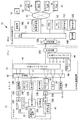
- FIG. 1 is a block diagram showing a communication configuration of the wind power generation system 10 according to the present embodiment.
- a wind power generation system 10 that is a wind farm includes a wind power generation device 12, a SCADA (machine side device) 14, and a SCADA (central operation room) 16.
- the wind power generation device 12 and the SCADA 14 are installed on the ocean.
- the SCADA 16 is installed at a land substation where power is transmitted from the wind power generator 12.
- the SCADA 14 and the SCADA 16 include optical termination boxes 20A and 20B, respectively, and communication (communication by Ethernet (registered trademark)) is possible by the optical cable 22.
- maintenance personnel who maintain the wind power generation system 10 are resident in the SCADA 16 as an example, but may be resident in other places different from the SCADA 16.
- the wind power generator 12 transmits / receives various data to / from the information processing apparatus (maintenance terminal 36C and maintenance terminal 36D) provided in the SCADA 16 and the client terminal 66 via the SCADA 14.
- Various controls can be performed by the maintenance terminal and the client terminal 66 provided in the SCADA 16.
- the various data refers to operation data (including trip data) transmitted from the wind power generator 12, control for controlling the wind power generator 12 transmitted from the maintenance terminal provided in the SCADA 16 and the client terminal 66. Signal etc.
- the maintenance terminal 36D sets the trip data signal of the wind turbine generator 12, changes the control software, collects and changes control parameters, sets the date and time of the wind turbine controller 30 to be described later, NVRAM (Non Volatile in the wind turbine controller). It is possible to collect and change data stored in RAM (nonvolatile RAM), obtain operation data that can be sampled at a higher speed than SCADA 14, and the like.
- the wind power generator 12 includes a windmill control device 30 that controls the entire wind power generator 12 in its nacelle.
- the windmill control device 30 receives data output from various devices constituting the wind turbine generator 12 and generates operation data indicating the operation state of the wind turbine generator 12.
- the windmill control device 30 is connected to a switching hub (SW-HUB) 32A.
- the switching hub 32A is connected to a remote I / O 34A and a maintenance terminal 36A, and a switching hub 32B provided under the tower of the wind turbine generator 12. Has been.
- each switching hub used in the present embodiment also has a function of a media converter (M / C) for connecting different transmission media and mutually converting signals.
- M / C media converter
- any conventionally known communication standard may be used as a communication standard (protocol or the like) between devices unless otherwise specified.
- the windmill control device 30 can communicate with the SCADA 14 by serial communication (for example, RS-232C) via the media converter 38A.
- a converter control device 40 is connected to the windmill control device 30.
- the converter control device 40 is a control device for a power conversion device provided in the wind turbine generator 12, and operation data is also generated in the converter control device 40.
- the converter control device 40 can also communicate with the SCADA 14 by serial communication (for example, RS-232C) via the media converter 38B.
- the SCADA 14 relays data transmission between the wind power generator 12 and the terminal provided in the SCADA 16, and the main switching hub 42 and the standby switching hub 44, and the data transmission between the wind power generator 12 and the terminal provided in the SCADA 16
- a network switch 46 for switching the relay to the main switching hub 42 or the standby switching hub 44 is provided. Normally, data transmission between the wind power generator 12 and the terminal included in the SCADA 16 is performed via the permanent switching hub 42. Even in a normal case, the power of the standby switching hub 44 is turned on.
- a spare remote I / O 48 is connected to the spare switching hub 44, and based on a switching command from the maintenance terminal and the client terminal 66 input by the spare remote I / O 48 via the spare switching hub 44. Switching by the network switch 46 is executed.
- the spare remote I / O 48 also turns on / off the power to the main switching hub 42 or the windmill control device 30 based on a maintenance command input via the spare switching hub 44 and a reset command from the client terminal 66. It can be executed.
- the permanent switching I / O 50 is connected to the permanent switching hub 42, and the permanent remote I / O 50 turns the power supply to the standby switching hub 44 on and off via the permanent switching hub 42. It can be executed based on the input maintenance terminal and a reset command from the client terminal 66.
- the main remote I / O 50 includes a main system (a transmission system including the main switching hub 42 and the main remote I / O 50) and a backup system (the backup switching hub 44 and the backup remote I / O 48).
- a self-diagnosis function is provided for monitoring the normality of the network status with the transmission system. For example, the self-diagnosis function transmits a predetermined signal at predetermined intervals to devices constituting the main system or the standby system, and monitors the normality of the network state depending on whether a signal corresponding to the predetermined signal is returned.
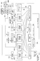
- FIG. 2 is a block diagram showing the relationship between the devices connected to the ports provided in the main switching hub 42 and the standby switching hub 44.
- the main switching hub 42 is supplied with power from the power source 52 via the power switch 50A
- the standby switching hub 44 is supplied with power from the power source 52 via the power switch 50B.
- the power switch 50 ⁇ / b> A turns on and off the power to the main switching hub 42 in response to a reset command from the spare remote I / O 48 connected to the spare switching hub 44.
- the power switch 50B turns on / off the power to the standby switching hub 44 in response to a reset command from the permanent remote I / O 50 connected to the permanent switching hub 42.
- the wind turbine control device 30, the switching hub 32A, the switching hub 32B, and the remote I / O 34B are supplied with electric power through the power switch 50C, and the power switch 50C is a spare connected to the spare switching hub 44.
- the power to the wind turbine control device 30, the switching hub 32A, the switching hub 32B, and the remote I / O 34B is turned on and off.
- the standby remote I / O 48 can reset the power of the primary remote I / O 50, and the primary remote I / O 50 can reset the power of the standby remote I / O 48. Yes.
- the main switching hub 42 and the standby switching hub 44 are connected to various devices via a network switch 46.
- the network switch 46 includes a plurality of Ethernet switches 46A (Ethernet switch 46A-1 to Ethernet switch 46A-5).
- the main switching hub 42 and the standby switching hub 44 are connected to the converter 54A via the Ethernet switch 46A-1, and connected to the switching hub 32B via the Ethernet switch 46A-2.
- the main remote I / O 50 is connected via the switch 46A-3
- the RTU (Remote Terminal Unit) 56 is connected via the Ethernet switch 46A-4
- the converter 54B is connected via the Ethernet switch 46A-5. It is connected.
- the converter 54A converts serial communication (RS-232C) and Ethernet communication, and is connected to the windmill control device 30 via the media converter 38A.
- the RTU 56 sequentially stores operation data transmitted from the wind turbine generator 12.
- the converter 54B is connected to the converter control device 40 via the media converter 38B.
- the main switching hub 42 and the standby switching hub 44 are connected to the optical termination box 20A, and are connected to the switching hub 32C installed in the SCADA 16 through the optical cable 22 and the optical termination box 20B.
- one set of the optical cable 22 is provided for each of the main system and the standby system.
- the present invention is not limited thereto, and two or more sets may be provided for each of the main system and the standby system. It is not necessary to divide it with.
- Each port of the switching hub 32C includes a converter 54C installed in the SCADA 16, a network monitoring terminal 60, a WEB server 62, a DB server 64, a maintenance terminal 36C, a maintenance terminal 36D, a converter 54D, and an Internet line 65.
- a client terminal 66 is connected through the network.
- the converter 54C and the converter 54D convert Ethernet communication and serial communication, and the converter 54C transmits a control signal for operating the wind turbine generator 12 to the wind turbine generator 12 by serial communication.
- a portable information processing terminal HOT (Handy Operation Terminal) 68 is connectable.
- the network monitoring terminal 60 monitors the normality of the communication network composed of the SCADAs 14 and 16 and the wind power generator 12 using a conventionally known network monitoring protocol (software) or the like.
- the DB server 64 sequentially stores the operation data of the wind turbine generator 12 transmitted via the SCADA 14.
- the maintenance terminal 36 ⁇ / b> C and the client terminal 66 are terminals (hereinafter referred to as “SCADA terminals”) that display the operation data transmitted via the SCADA 14 on the screen via the WEB server 62 and transmit commands to the SCADA 14. is there.
- SCADA terminals terminals
- the maintenance terminal 36D is a SCADA terminal, similar to the maintenance terminal 36C, but is capable of operating the wind power generator 12 by transmitting a control signal to the wind power generator 12. That is, it has the same function as the HOT 68 described above.
- the operation data transmitted from the converter control device 40 can be sequentially stored.
- the switching hub provided in the SCADA or the switching hub provided in the wind power generator 12 is used. If a malfunction is discovered, maintenance personnel up to the wind power generator 12 go from the stationed location (central operation room) to the remote wind power generator 12 and reset the power of each switching hub as a means of recovery. There was a need. Then, if the problem is not resolved by resetting the power, the failed network device is replaced or repaired.
- the maintenance staff operates the maintenance terminal 36C or the maintenance terminal 36D, which is the SCADA terminal, so that the switching command is transferred from the SCADA terminal to the spare switching hub 44.
- the spare switching hub 44 outputs a switching command to the spare remote I / O 48.
- the spare remote I / O 48 executes transmission path switching by the network switch 46 based on a switching command input via the spare switching hub 44.
- the switching command includes a standby switching command for switching the data transmission path from the primary switching hub 42 to the standby switching hub 44, and a permanent switching command for switching the data transmission path from the standby switching hub 44 to the primary switching hub 42.
- a backup switching command is input from the SCADA terminal to the backup remote I / O 48 via the backup switching hub 44. Therefore, the data transmission path is switched from the main switching hub 42 to the standby switching hub 44, and even if the main switching hub 42 malfunctions, the problem of data transmission is solved.
- the wind power generation system 10 can solve the problem of data transmission due to the malfunction of the main switching hub 42 from a remote place without the maintenance personnel going to the wind power generation device 12.
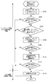
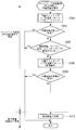
- FIG. 3 shows a flow of power reset processing that is performed when there is an abnormality in the main system, that is, when operation data is not displayed on the SCADA terminal, or when it is assumed that the processing of the wind turbine control device 30 is stopped.
- the data transmission path is switched from the main switching hub 42 to the standby switching hub 44 between step 104 and step 106 described later as part of the failure search operation.
- step 100 the mains switching hub 42 is reset. This power reset is performed by transmitting a reset command to the main switching hub 42 by a remote command from the SCADA terminal.
- step 102 the maintenance staff or the network monitoring terminal 60 determines whether or not the operation data transmitted from the wind power generator 12 via the SCADA 14 is displayed on the SCADA terminal. If it is displayed, the process ends because the data transfer problem has been resolved. If not, the process proceeds to step 104.
- step 104 whether or not there is any abnormality in the communication path, the cable, the power source, the switching hub, etc. between the wind power generator 12 and the SCADA terminal via the SCADA 14 using the network monitoring terminal 60 or the like. Judgment. If there is no abnormality, the present process is terminated, and other causes (such as a failure of the SCADA terminal) are resolved to solve the problem of data transfer. On the other hand, if there is an abnormality, the process proceeds to step 106.
- step 106 the main switching hub 42 is reset by remote control. That is, a reset command for resetting the power of the main switching hub 42 is transmitted from the SCADA terminal to the spare remote I / O 48 via the spare switching hub 44.
- the spare remote I / O 48 transmits the reset command to the power switch 50A, and causes the power switch 50A to reset the power of the main switching hub 42.
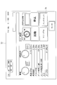
- FIG. 4 shows a remote maintenance screen 69 displayed on the SCADA terminal when the power reset is performed by this remote operation.
- the remote maintenance screen 69 shown in FIG. 4 displays a list of network devices that can perform power reset by remote operation.
- the maintenance staff selects a network device to be reset (“Reset”). Click to reset the power supply by remote control.
- RTU indicates that the power of the RTU 56 is reset
- SW-HUB-3 indicates that the main switching hub 42 is reset
- SW-HUB- "4" indicates a power reset of the standby switching hub 44
- CNV-1 indicates a power reset of the converter 54A
- CNV-2 indicates a power reset of the converter 54B
- RI / O- "3” indicates power reset of the main remote I / O 50
- RI / O-4" indicates power reset of the spare remote I / O 48
- hard SS indicates power reset of the safety system by hardware
- Windmill control device power supply is a power reset of the windmill control device 30, the switching hub 32A, the switching hub 32B, and the remote I / O 34B. Show.
- remote switching screen 69 enables switching between the main switching hub 42 and the standby switching hub 44.
- step 108 the maintenance staff or the network monitoring terminal 60 determines whether or not the operation data transmitted from the wind power generator 12 via the SCADA 14 is displayed on the SCADA terminal. If it is displayed, the process ends because the data transfer problem has been resolved. If not, the process proceeds to step 110.
- step 110 the wind turbine controller 30 is reset by remote control. That is, the maintenance staff selects “wind turbine control device power” on the remote maintenance screen 69 shown in FIG. 4 to reset the power of the wind turbine control device 30, the switching hub 32A, and the switching hub 32B.
- a reset command for resetting the power supply of the wind turbine controller 30, the switching hub 32 ⁇ / b> A, and the switching hub 32 ⁇ / b> B is transmitted from the SCADA terminal to the spare remote I / O 48 via the spare switching hub 44.
- the spare remote I / O 48 transmits the reset command to the power switch 50C, and causes the power switch 50C to reset the power of the windmill control device 30, the switching hub 32A, and the switching hub 32B.
- step 112 the maintenance staff or the network monitoring terminal 60 determines whether or not the operation data transmitted from the wind power generator 12 via the SCADA 14 is displayed on the SCADA terminal. If it is displayed, the process ends because the data transfer problem has been resolved. If not, the process proceeds to step 114.
- step 114 the power transmission reset does not solve the problem of data transmission. Therefore, the maintenance staff goes to the wind power generator 12 and the SCADA 14, repairs the malfunction of the network equipment, and ends this process. In addition, it may be at the time of the next maintenance that it goes to the wind power generator 12 and SCADA14.
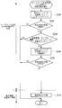
- FIG. 5 shows a flow of a power reset process for the main remote I / O 50 that is performed when an abnormality is detected in the main remote I / O 50 by the self-diagnosis function of the main remote I / O 50.
- the data transmission path is switched from the main switching hub 42 to the standby switching hub 44 by the maintenance staff together with the discovery of the abnormality.
- step 200 the power is reset for the main remote I / O 50.
- This power reset is performed by transmitting a reset command to the permanent remote I / O 50 via the permanent switching hub 42 by a remote command from the SCADA terminal.
- next step 202 it is determined whether or not the abnormality of the main system has been resolved by the self-diagnosis function of the main remote I / O 50. If the problem has been resolved, the present process is terminated. Migrate to
- step 204 maintenance personnel are inspected using the network monitoring terminal 60 or the like to determine whether or not there is any abnormality in the communication path, cable, power supply, switching hub, etc. between the wind turbine generator 12 and the SCADA terminal via the SCADA 14. Judgment. If there is no abnormality, the present process is terminated, and other causes (such as a failure of the SCADA terminal) are resolved, so that the abnormality of the main system is resolved.
- step 206 the power of the main remote I / O 50 is reset by remote control. That is, the maintenance staff selects “RI / O-3” on the remote maintenance screen 69 shown in FIG. 4 to reset the power supply of the main remote I / O 50.
- a reset command for resetting the power of the main remote I / O 50 is transmitted from the SCADA terminal to the spare remote I / O 48 via the spare switching hub 44.
- the spare remote I / O 48 transmits the reset command to the power switch 50A corresponding to the permanent remote I / O 50, and causes the power switch to reset the power of the permanent remote I / O 50.
- the power to the main remote I / O 50 is supplied in the order of the power source 52 from the power switch 50A and the power switch 50A to the main remote I / O 50.
- next step 208 it is determined whether or not the abnormality of the main system has been resolved by the self-diagnosis function of the main remote I / O 50. If the problem has been resolved, the process is terminated. Migrate to
- Step 210 since the abnormality of the main system is not solved by the power reset, the maintenance staff goes to the wind power generator 12 and the SCADA 14, repairs the failure of the network equipment, and ends this processing. In addition, it may be at the time of the next maintenance that it goes to the wind power generator 12 and SCADA14.
- FIG. 6 shows a flow of power reset processing for the standby switching hub 44 that is performed when an abnormality is detected in the standby system by the diagnostic function of the network monitoring terminal 60.
- the data transmission path remains the main switching hub 42.
- step 300 the power is reset for the standby switching hub 44.
- This power reset is performed by transmitting a reset command to the standby switching hub 44 by a remote command from the SCADA terminal.
- step 302 it is determined whether or not the abnormality of the standby system has been eliminated by the diagnostic function of the network monitoring terminal 60. If the abnormality is eliminated, the present process is terminated, and if not eliminated, the process proceeds to step 304. .
- step 304 whether or not there are any abnormalities in the communication path, cable, power supply, switching hub, etc. between the wind turbine generator 12 and the SCADA terminal via the SCADA 14 using the network monitoring terminal 60, etc. Judgment. If there is no abnormality, the present process is terminated, and other causes (such as a failure of the SCADA terminal) are eliminated to eliminate the abnormality of the standby system. On the other hand, if there is an abnormality, the process proceeds to step 306.
- step 306 the standby switching hub 44 is reset by remote control. That is, the maintenance staff selects “SW-HUB-4” on the remote maintenance screen 69 shown in FIG. As a result, a reset command for resetting the power of the standby switching hub 44 is transmitted from the SCADA terminal to the permanent remote I / O 50 via the permanent switching hub 42.
- the main remote I / O 50 transmits the reset command to the power switch 50B corresponding to the spare switching hub 44, and causes the power switch 50B to reset the power of the spare switching hub 44.
- step 308 it is determined whether or not the abnormality in the standby system has been eliminated by the diagnostic function of the network monitoring terminal 60. If the abnormality has been eliminated, the process is terminated. If not, the process proceeds to step 310. .
- step 310 since the abnormality of the standby system is not eliminated by the power reset, the maintenance staff goes to the wind power generator 12 and the SCADA 14, repairs the network device, and finishes this process. In addition, it may be at the time of the next maintenance that it goes to the wind power generator 12 and SCADA14.
- FIG. 7 shows the flow of power reset processing for the backup remote I / O 48 that is performed when an abnormality is detected in the backup remote I / O 48 by the diagnostic function of the network monitoring terminal 60.
- the data transmission path remains the main switching hub 42.
- step 400 power is reset for the spare remote I / O 48.
- This power reset is performed by transmitting a reset command to the spare remote I / O 48 via the spare switching hub 44 by a remote command from the SCADA terminal.
- next step 402 it is determined whether or not the abnormality of the backup remote I / O 48 has been solved by the diagnostic function of the network monitoring terminal 60. If it has been solved, the process is terminated.
- step 404 maintenance personnel are checked using the network monitoring terminal 60 or the like to determine whether or not there is any abnormality in the communication path, cable, power supply, switching hub, etc. between the wind power generator 12 and the SCADA terminal via the SCADA 14. Judgment. If there is no abnormality, the present process is terminated, and other causes (failure of the SCADA terminal, etc.) are resolved to eliminate the abnormality of the standby system.
- step 406 the power of the backup remote I / O 48 is reset by remote control. That is, the maintenance staff selects “RI / O-4” on the remote maintenance screen 69 shown in FIG. 4 to reset the power supply of the spare remote I / O 48.
- a reset command for resetting the power of the standby remote I / O 48 is transmitted from the SCADA terminal to the permanent remote I / O 50 via the permanent switching hub 42.
- the main remote I / O 50 transmits the reset command to the power switch 50B corresponding to the backup remote I / O 48, and causes the power switch to reset the power of the backup remote I / O 48.
- next step 408 it is determined whether or not the abnormality of the spare remote I / O 48 has been solved by the diagnostic function of the network monitoring terminal 60. If the abnormality is eliminated, the process is terminated. Migrate to
- Step 410 since the abnormality of the standby system is not resolved by the power reset, the maintenance staff goes to the wind power generator 12 and the SCADA 14, repairs the network device, and ends this processing. In addition, it may be at the time of the next maintenance that it goes to the wind power generator 12 and SCADA14.
- the converters 54A and 54B that convert Ethernet communication and RS-232C and are connected to the windmill control device 30 or the converter control device 40 are provided as a permanent switching hub of the SCADA 14. 42 and a port of the spare switching hub 44.
- Converters 54C and 54D for converting Ethernet communication and RS-232C are connected to a port of the switching hub 32C of the SCADA 16. Therefore, in the wind power generation system 10 according to the present embodiment, the maintenance operation of the wind power generator 12 can be performed from the SCADA 16 by maintenance personnel by connecting the HOT 68 to the converter 54C of the SCADA 16.
- FIG. 9 shows the flow of processing when a reason for performing a maintenance operation occurs.
- a reason for performing a maintenance operation for example, when performing a remote reset when the safety system is activated, the yaw limit switch is activated due to the occurrence of a cable twist.
- the yaw limit switch is activated due to the occurrence of a cable twist.
- step 500 the HOT 68 is connected to the converter 54C.
- FIG. 10 shows an example of the menu screen 72 displayed on the HOT 68.
- the HOT 68 displays data indicating the operating state of the wind turbine generator 12 such as the wind speed, the wind direction, and the nacelle direction.
- start”, stop”, “manual”, “maintenance”, etc. are displayed on the HOT 68, and the button 74 labeled “maintenance” is pressed, whereby the wind turbine generator 12 enters the maintenance mode. To be migrated.
- the maintenance operation for the equipment included in the wind turbine generator 12 is performed using the HOT 68.
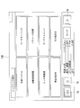
- FIG. 11 shows an example of a menu screen 74A displayed on the HOT 68 when a maintenance operation is performed.
- the menu screen 74A displays a list of systems and devices that are subject to maintenance operations, and when the page switching button 76 is pressed, another menu screen as shown in FIG.
- the screen of the HOT 68 is switched to 74B.
- the maintenance staff selects a system or device to be maintained by pressing a button displayed on the menu screens 74A and 74B, and switches the screen of the HOT 68 to the maintenance operation screen.
- Various operation buttons and the like for performing maintenance are displayed on the maintenance operation screen, and a control signal is transmitted to the wind turbine generator 12 by clicking the operation button.
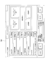
- FIG. 13 shows a maintenance operation screen 78A displayed on the HOT 68 when the “control oil system” shown in FIG. 11 is pressed, and various pumps, valves, etc. can be turned on / off.
- FIG. 14 is a maintenance operation screen 78B displayed on the HOT 68 by pressing the “yaw system” shown in FIG. 11, and the turning on and off of the yaw limit bypass and the turning direction of the nacelle can be operated.
- FIG. 15 shows a maintenance operation screen 78C displayed on the HOT 68 when the “cooling system” shown in FIG. 11 is pressed, and it is possible to select on / off of a pump, a fan, and the like.
- the “other settings” on the menu screen shown in FIG. 12 includes trip data signal setting, control software change, control parameter collection and change, date and time setting of the windmill control device 30, and NVRAM in the windmill control device. This includes collecting and changing data stored in (Non Volatile RAM).
- step 506 when the predetermined maintenance operation is completed, the maintenance staff determines whether or not to continue the maintenance operation. If it is determined that the maintenance operation is to be continued, the process returns to step 504. 508.
- the SCADA 14 is provided with the ports for transmitting the control signal transmitted from the HOT 68 to the wind power generator 12 in the main switching hub 42 and the standby switching hub 44. Can be used to perform various maintenance on the wind turbine generator 12 from a remote location.
- the maintenance terminal 36D also has the same function as the HOT 68. Since the converter 54D is connected to the maintenance terminal 36D, the maintenance operation of the converter control device 40 using the maintenance terminal 36D can be performed from the SCADA 16.
- a remote maintenance operation can be performed without using the converters 54A to 54D.
- the maintenance operation may be performed from the client terminal 66 connected to the Internet line 65 using a wired, wireless, or mobile phone.
- the wind power generator 12 and the SCADA 14 are installed on the ocean.
- the present invention is not limited to this, and the wind power generator 12 and the SCADA 14 are installed on the land. It is good also as a form.
- switching between the main switching hub 42 and the standby switching hub 44 by the network switching unit 46 is performed when a switching command is automatically switched from the SCADA terminal when the network monitoring terminal 60 detects an abnormality in the main system. This may be done by inputting to the spare remote I / O 48 via the hub 44.
- Wind Power Generation System 12 Wind Power Generation Equipment 14 SCADA 16 Central operation room 36D Maintenance terminal 42 Main switching hub 44 Backup switching hub 46 Network switch 48 Backup remote I / O 50 Remote I / O 68 HOT
Abstract
Description
このようなウインドファームにおいて、SCADAと風力発電装置とは、通信回線(例えばEthernet(登録商標)をベースとした通信ネットワーク)によって接続されている。 In a wind farm composed of a plurality of wind power generators, SCADA (Supervisory Control And Data Acquisition) is used as a remote monitoring device that monitors the operating state of the wind power generator.
In such a wind farm, SCADA and the wind power generator are connected by a communication line (for example, a communication network based on Ethernet (registered trademark)).
通信回線に障害が発生した場合の対処方法として、特許文献2には、閉域IP網及びISDN交換機網という2系統の異なる種類の通信回線でPOS端末とホストシステムとの間を接続し、閉域IP網に障害が生じた場合にISDN交換機網に切り替える通信システムが記載されている。 In addition, when a failure occurs in the communication network, data transmission may be difficult.
As a coping method when a failure occurs in a communication line,
そして、リングトポロジーを実現する風力発電装置側のスイッチングハブが不調、あるいは故障した場合、スイッチングハブの電源リセットを実施することによって、不調等を解消する場合がある。電源リセットによって、スイッチングハブを再起動するためには、第1の方法として、遠隔地である中央制御室の端末(情報処理装置)から対象の風力発電装置側のスイッチングハブに対し、ネットワーク経由でリセットコマンドを送信する方法があり、第2の方法として、風力発電装置にメンテナンス要員が出向き、スイッチングハブの電源を切入操作する方法がある。 Furthermore, in order to cope with a failure in a communication line, a switching hub for connecting to a communication network is installed in the wind turbine generator, and a ring topology may be configured in the wind farm for redundancy.
When the switching hub on the wind power generator side that realizes the ring topology malfunctions or fails, the malfunction or the like may be resolved by resetting the power of the switching hub. In order to restart the switching hub by resetting the power supply, as a first method, a terminal (information processing device) in the central control room which is a remote location is connected to the switching hub on the target wind turbine generator side via the network. There is a method of transmitting a reset command. As a second method, there is a method in which maintenance personnel are sent to the wind turbine generator and the switching hub is turned on and off.
ここで、本設スイッチングハブが不調となり、本設スイッチングハブを介した風力発電装置と情報処理装置との間におけるデータ伝送に不具合が生じた場合、遠隔地に設けられている情報処理装置が、本設スイッチングハブから予備スイッチングハブに切り替える切替信号を予備スイッチングハブへ送信する。予備スイッチングハブは、切替信号を第1制御手段に入力し、第1制御手段は、風力発電装置と情報処理装置との間におけるデータ伝送の中継を本設スイッチングハブから予備スイッチングハブに切り替えるように、切替手段を制御する。 Usually, data transmission between the wind turbine generator and the information processing apparatus is performed via a permanent switching hub. Even in a normal case, the power of the standby switching hub is turned on.
Here, when the main switching hub becomes malfunctioning and there is a problem in data transmission between the wind turbine generator and the information processing device via the main switching hub, the information processing device provided in the remote place is A switching signal for switching from the main switching hub to the spare switching hub is transmitted to the spare switching hub. The standby switching hub inputs a switching signal to the first control means, and the first control means switches the data transmission relay between the wind power generator and the information processing apparatus from the main switching hub to the standby switching hub. , Controlling the switching means.
これにより、本設スイッチングハブが正常に機能している状態において、予備スイッチングハブに不調が発見された場合に、電源リセットによる不調の解消を実行することができ、予備スイッチングハブを正常に保つことができる。 According to the above configuration, the second control unit connected to the main switching hub turns on and off the power to the spare switching hub based on the reset signal from the information processing device input via the spare switching hub. As a result, the standby switching hub can be reset from a remote location.
As a result, when a malfunction occurs in the standby switching hub while the main switching hub is functioning normally, the malfunction can be resolved by resetting the power supply, and the standby switching hub can be maintained normally. Can do.
図1に示されるようにウインドファームである風力発電システム10は、風力発電装置12、SCADA(機側装置)14、及びSCADA(中央操作室)16を備える。本実施形態に係る風力発電システム10は、一例として、風力発電装置12及びSCADA14が、洋上に設置される。一方、SCADA16が、風力発電装置12から電力が送電される陸上の変電所に設置される。また、SCADA14とSCADA16は、各々光成端箱20A,20Bを備え、光ケーブル22によって通信(一例としてEthernet(登録商標))による通信)が可能とされている。 FIG. 1 is a block diagram showing a communication configuration of the wind
As shown in FIG. 1, a wind
なお、保守端末36Dは、風力発電装置12のトリップデータの信号設定、制御用ソフトウェア変更、制御パラメータの収集や変更、後述する風車制御装置30の日付や時刻設定、風車制御装置内NVRAM(Non Volatile RAM:不揮発性RAM)が記憶しているデータの収集や変更、SCADA14よりも高速サンプリング可能な運転データの取得等が可能とされている。 The
The maintenance terminal 36D sets the trip data signal of the
風車制御装置30は、スイッチングハブ(SW-HUB)32Aと接続され、スイッチングハブ32Aには、リモートI/O34A及び保守端末36A、並びに風力発電装置12のタワー下に設けられたスイッチングハブ32Bが接続されている。 The
The
また、風車制御装置30は、メディアコンバータ38Aを介して、シリアル通信(例えばRS-232C)によってSCADA14と通信可能とされている。 Connected to the
The
コンバータ制御装置40も、メディアコンバータ38Bを介して、シリアル通信(例えばRS-232C)によってSCADA14と通信可能とされている。 Furthermore, a
The
通常、風力発電装置12とSCADA16が備える端末との間におけるデータ伝送は、本設スイッチングハブ42を介して行われる。なお、通常の場合でも、予備スイッチングハブ44の電源はオンとされている。 The
Normally, data transmission between the
さらに、本設リモートI/O50には、本設系統(本設スイッチングハブ42と本設リモートI/O50とを含む伝送系統)と予備系統(予備スイッチングハブ44と予備リモートI/O48とを含む伝送系統)とのネットワーク状態の正常性を監視する自己診断機能が備えられている。自己診断機能は、例えば、本設系統又は予備系統を構成する機器に対して所定間隔で、所定信号を送信し、所定信号に対応した信号の返信の有無によってネットワーク状態の正常性を監視する。 Further, the permanent switching I /
Further, the main remote I /
そして、電源スイッチ50Aは、予備スイッチングハブ44に接続されている予備リモートI/O48からのリセットコマンドに応じて、本設スイッチングハブ42への電力のオン及びオフを行う。一方、電源スイッチ50Bは、本設スイッチングハブ42に接続されている本設リモートI/O50からのリセットコマンドに応じて、予備スイッチングハブ44への電力のオン及びオフを行う。 As shown in FIG. 2, the
The
ネットワーク切替器46は、複数のEthernet切替器46A(Ethernet切替器46A-1~Ethernet切替器46A-5)で構成されている。 The
The
RTU56は、風力発電装置12から送信されてくる運転データを逐次記憶する。
変換器54Bは、メディアコンバータ38Bを介してコンバータ制御装置40と接続される。 The
The
The
すなわち、本設スイッチングハブ44に不調が生じた場合は、予備切替コマンドが、SCADA端末から予備スイッチングハブ44を介して予備リモートI/O48へ入力される。従って、データの伝送経路は、本設スイッチングハブ42から予備スイッチングハブ44へ切り替えられ、本設スイッチングハブ42が不調となっても、データ伝送の不具合は解消される。 The spare remote I /
That is, when a malfunction occurs in the
図4に示される遠隔メンテナンス画面69には、遠隔操作による電源リセットを行うことができるネットワーク機器の一覧が表示され、メンテナンス要員は、電源リセットを行う対象となるネットワーク機器を選択(「リセット」のクリック)することによって、遠隔操作による電源リセットを行う。
なお、一覧として表示されているネットワーク機器のうち、「RTU」はRTU56を電源リセットすることを示し、「SW-HUB-3」は本設スイッチングハブ42の電源リセットを示し、「SW-HUB-4」は予備スイッチングハブ44の電源リセットを示し、「CNV-1」は変換器54Aの電源リセットを示し、「CNV-2」は変換器54Bの電源リセットを示し、「R-I/O-3」は本設リモートI/O50の電源リセットを示し、「R-I/O-4」は予備リモートI/O48の電源リセットを示し、ハードSSはハードウェアによるセーフティシステムの電源リセットを示し、「風車制御装置電源」は風車制御装置30、スイッチングハブ32A、スイッチングハブ32B、及びリモートI/O34Bの電源リセットを示す。 FIG. 4 shows a
The
Of the network devices displayed as a list, “RTU” indicates that the power of the
そのため、風力発電装置12に対するメンテナンス操作を必要とする場合は、図8に示すように、メンテナンス要員がHOT68を携え、風力発電装置12まで出向き、RS-232Cによって制御盤70を介して風車制御装置30とHOT68とを接続し、HOT68によって制御信号を風車制御装置30へ送信することによって、風力発電装置12のメンテナンス操作を行っていた。
すなわち、従来の風力発電システム10では、メンテナンス操作の全てを風力発電装置12で行う必要があった。 In the conventional wind
Therefore, when a maintenance operation for the
That is, in the conventional wind
図10は、HOT68に表示されるメニュー画面72の一例を示す。HOT68には、風速、風向、ナセル方向等の風力発電装置12の運転状態を示すデータが表示される。そして、HOT68には、「起動」、「停止」、「マニュアル」、「メンテナンス」等が表示され、「メンテナンス」と表示されたボタン74が押されることによって、風力発電装置12は、メンテナンスモードへ移行される。 In the next step 502, the
FIG. 10 shows an example of the
そして、メンテナンス要員は、メニュー画面74A,74Bに表示されるボタンを押すことによって、メンテナンス対象となるシステム又は機器を選択し、HOT68の画面をメンテナンス操作画面へ切り替える。
メンテナンス操作画面には、メンテナンスを行うための各種操作ボタン等が表示され、該操作ボタンをクリック等することによって、風力発電装置12へ制御信号が送信される。 FIG. 11 shows an example of a
Then, the maintenance staff selects a system or device to be maintained by pressing a button displayed on the menu screens 74A and 74B, and switches the screen of the HOT 68 to the maintenance operation screen.
Various operation buttons and the like for performing maintenance are displayed on the maintenance operation screen, and a control signal is transmitted to the
図14は、図11に示される「ヨーシステム」を押すことによって、HOT68に表示されるメンテナンス操作画面78Bであり、ヨーリミットバイパスのオン及びオフ、ナセルの旋回方向が操作可能とされている。
図15は、図11に示される「冷却システム」を押すことによって、HOT68に表示されるメンテナンス操作画面78Cであり、ポンプやファン等のオン及びオフ等が選択可能とされている。 FIG. 13 shows a
FIG. 14 is a
FIG. 15 shows a
また、保守端末36DもHOT68と同様の機能を有している。保守端末36Dは、変換器54Dが接続されているので、SCADA16から保守端末36Dを用いたコンバータ制御装置40のメンテナンス操作が可能とされている。 As described above, the
The maintenance terminal 36D also has the same function as the
12 風力発電装置
14 SCADA
16 中央操作室
36D 保守端末
42 本設スイッチングハブ
44 予備スイッチングハブ
46 ネットワーク切替器
48 予備リモートI/O
50 本設リモートI/O
68 HOT 10 Wind
16 Central operation room
50 Remote I / O
68 HOT
Claims (8)
- 風力発電装置と情報処理装置との間でデータを送受信する遠隔監視装置であって、
前記風力発電装置と情報処理装置との間におけるデータ伝送の中継を行う本設スイッチングハブと、
前記風力発電装置と情報処理装置との間におけるデータ伝送の中継を行う予備スイッチングハブと、
前記風力発電装置と情報処理装置との間におけるデータ伝送の中継を、前記本設スイッチングハブ又は前記予備スイッチングハブに切り替える切替手段と、
前記予備スイッチングハブに接続されると共に、前記予備スイッチングハブを介して入力される情報処理装置からの切替信号に基づいて、前記切替手段による切り替えを実行する第1制御手段と、
を備えた遠隔監視装置。 A remote monitoring device that transmits and receives data between a wind turbine generator and an information processing device,
A permanent switching hub that relays data transmission between the wind turbine generator and the information processing device;
A standby switching hub that relays data transmission between the wind turbine generator and the information processing device;
Switching means for switching the relay of data transmission between the wind power generator and the information processing apparatus to the main switching hub or the standby switching hub;
A first control unit that is connected to the spare switching hub and that performs switching by the switching unit based on a switching signal from an information processing device input via the spare switching hub;
Remote monitoring device with - 前記第1制御手段は、前記予備スイッチングハブを介して入力される情報処理装置からのリセット信号に基づいて、前記本設スイッチングハブに対する電源のオン及びオフを実行する請求項1記載の遠隔監視装置。 2. The remote monitoring device according to claim 1, wherein the first control unit executes power on and off for the main switching hub based on a reset signal from the information processing device input via the spare switching hub. .
- 前記第1制御手段は、前記予備スイッチングハブを介して入力される情報処理装置からのリセット信号に基づいて、前記風力発電装置を制御する風車制御装置に対する電源のオン及びオフを実行する請求項1記載の遠隔監視装置。 2. The first control unit executes power on and off for a wind turbine control device that controls the wind power generation device based on a reset signal from an information processing device input via the backup switching hub. The remote monitoring device described.
- 前記本設スイッチングハブに接続されると共に、前記予備スイッチングハブに対する電源のオン及びオフを、前記本設スイッチングハブを介して入力される情報処理装置からのリセット信号に基づいて実行する第2制御手段を備えた請求項1記載の遠隔監視装置。 Second control means that is connected to the main switching hub and that turns on and off the power to the spare switching hub based on a reset signal from the information processing device input via the main switching hub The remote monitoring device according to claim 1, further comprising:
- 風力発電装置を制御する風車制御装置から受信した前記風力発電装置の運転状態を示す運転データを、通信回線を介して遠隔地に設置された情報処理装置へ送信する請求項1記載の遠隔監視装置。 The remote monitoring device according to claim 1, wherein operation data indicating an operation state of the wind turbine generator received from a wind turbine controller that controls the wind turbine generator is transmitted to an information processing device installed in a remote place via a communication line. .
- 前記本設スイッチングハブ及び前記予備スイッチングハブは、前記風力発電装置を操作するための可搬型の情報処理端末から送信された制御信号を前記風力発電装置へ送信するためのポートが設けられている請求項1記載の遠隔監視装置。 The main switching hub and the standby switching hub are provided with a port for transmitting a control signal transmitted from a portable information processing terminal for operating the wind power generator to the wind power generator. Item 1. The remote monitoring device according to Item 1.
- 風力発電装置、及び請求項1記載の遠隔監視装置が洋上に設置され、
前記第1制御手段は、陸上に設置された情報処理装置からの切替信号に基づいて、前記切替手段による切り替えを実行する風力発電システム。 The wind power generator and the remote monitoring device according to claim 1 are installed on the ocean,
The first control unit is a wind power generation system that performs switching by the switching unit based on a switching signal from an information processing device installed on land. - 風力発電装置と情報処理装置との間でデータを送受信するために、前記風力発電装置と情報処理装置との間におけるデータ伝送の中継を行う本設スイッチングハブ、前記風力発電装置と情報処理装置との間におけるデータ伝送の中継を行う予備スイッチングハブ、及び前記風力発電装置と情報処理装置との間におけるデータ伝送の中継を、前記本設スイッチングハブ又は前記予備スイッチングハブに切り替える切替手段を備える遠隔監視装置の制御方法であって、
前記予備スイッチングハブに接続されると共に、前記予備スイッチングハブを介して入力される情報処理装置からの切替信号に基づいて、前記切替手段による切り替えを実行する遠隔監視装置の制御方法。 In order to transmit and receive data between the wind power generator and the information processing apparatus, a permanent switching hub that relays data transmission between the wind power generator and the information processing apparatus, the wind power generator and the information processing apparatus, Remote monitoring comprising a standby switching hub that relays data transmission between the wind turbine generator and the information processing device, and a switching unit that switches the relay of data transmission between the wind turbine generator and the information processing device to the main switching hub or the standby switching hub An apparatus control method comprising:
A control method for a remote monitoring device, which is connected to the spare switching hub and performs switching by the switching means based on a switching signal from an information processing device input via the spare switching hub.
Priority Applications (5)
| Application Number | Priority Date | Filing Date | Title |
|---|---|---|---|
| EP11817499.4A EP2725745B1 (en) | 2011-06-22 | 2011-06-22 | Remote monitoring device, power generation system, and remote monitoring device control method |
| CN201180004360.3A CN102959900B (en) | 2011-06-22 | 2011-06-22 | Remote monitoring device, electricity generation system and the control method of remote monitoring device |
| KR1020127010620A KR20130031815A (en) | 2011-06-22 | 2011-06-22 | Remote monitoring apparatus, wind turbine generator system, and method of controlling remote monitoring apparatus |
| AU2011313837A AU2011313837A1 (en) | 2011-06-22 | 2011-06-22 | Remote monitoring apparatus, wind turbine generator system, and method of controlling remote monitoring apparatus |
| US13/232,307 US8977403B2 (en) | 2011-06-22 | 2011-09-14 | Remote monitoring apparatus, wind turbine generator system, and method of controlling remote monitoring apparatus |
Applications Claiming Priority (2)
| Application Number | Priority Date | Filing Date | Title |
|---|---|---|---|
| JP2011138031A JP5237416B2 (en) | 2011-06-22 | 2011-06-22 | Remote monitoring device, power generation system, and control method of remote monitoring device |
| JP2011-138031 | 2011-06-22 |
Related Child Applications (2)
| Application Number | Title | Priority Date | Filing Date |
|---|---|---|---|
| US13/232,307 Continuation US8977403B2 (en) | 2011-06-22 | 2011-09-14 | Remote monitoring apparatus, wind turbine generator system, and method of controlling remote monitoring apparatus |
| US13/232,307 Division US8977403B2 (en) | 2011-06-22 | 2011-09-14 | Remote monitoring apparatus, wind turbine generator system, and method of controlling remote monitoring apparatus |
Publications (1)
| Publication Number | Publication Date |
|---|---|
| WO2012176294A1 true WO2012176294A1 (en) | 2012-12-27 |
Family
ID=47422175
Family Applications (1)
| Application Number | Title | Priority Date | Filing Date |
|---|---|---|---|
| PCT/JP2011/064295 WO2012176294A1 (en) | 2011-06-22 | 2011-06-22 | Remote monitoring device, power generation system, and remote monitoring device control method |
Country Status (6)
| Country | Link |
|---|---|
| EP (1) | EP2725745B1 (en) |
| JP (1) | JP5237416B2 (en) |
| KR (1) | KR20130031815A (en) |
| CN (1) | CN102959900B (en) |
| AU (1) | AU2011313837A1 (en) |
| WO (1) | WO2012176294A1 (en) |
Cited By (1)
| Publication number | Priority date | Publication date | Assignee | Title |
|---|---|---|---|---|
| CN112787891A (en) * | 2021-01-26 | 2021-05-11 | 张俊峰 | Signal lamp system fault monitoring and collecting terminal and method |
Families Citing this family (10)
| Publication number | Priority date | Publication date | Assignee | Title |
|---|---|---|---|---|
| JP6280492B2 (en) * | 2014-11-14 | 2018-02-14 | 三菱重工業株式会社 | Wind power generation equipment |
| US11009842B2 (en) * | 2016-04-07 | 2021-05-18 | Vestas Wind Systems A/S | Data collection system for wind turbine data |
| CN107347003B (en) * | 2016-05-05 | 2020-06-26 | 中国船舶重工集团海装风电股份有限公司 | Method and device for automatically switching communication lines and wind generating set |
| KR101768810B1 (en) | 2016-06-02 | 2017-08-30 | 두산중공업 주식회사 | Wind farm supervision monitoring system |
| RU2629426C1 (en) * | 2016-11-07 | 2017-08-29 | Федеральное государственное бюджетное учреждение "16 Центральный научно-исследовательский испытательный ордена Красной Звезды институт имени маршала войск связи А.И. Белова" Министерства обороны Российской Федерации | Complex communication equipment room for transport network of field communication system |
| RU2652437C1 (en) * | 2017-08-04 | 2018-04-26 | Федеральное государственное бюджетное учреждение "16 Центральный научно-исследовательский испытательный ордена Красной Звезды институт имени маршала войск связи А.И. Белова" Министерства обороны Российской Федерации | Hardware control of communication |
| EP3695114A4 (en) * | 2017-10-14 | 2021-07-07 | EC&R Services, LLC | Systems and methods for remotely managing wind power generation |
| CN111255630B (en) * | 2020-03-24 | 2024-01-30 | 中国华能集团清洁能源技术研究院有限公司 | Wireless control system applied to wind turbine generator cabin and operation method |
| RU2752870C1 (en) * | 2020-04-20 | 2021-08-11 | Публичное акционерное общество "Информационные телекоммуникационные технологии" (ПАО "Интелтех") | Basic software and hardware complex for forming aviation communication system elements |
| CN113437800A (en) * | 2021-06-24 | 2021-09-24 | 国网山西省电力公司阳泉供电公司 | New forms of energy electricity generation monitoring platform |
Citations (2)
| Publication number | Priority date | Publication date | Assignee | Title |
|---|---|---|---|---|
| JP2005168144A (en) * | 2003-12-01 | 2005-06-23 | Tm T & D Kk | Distributed monitoring controller |
| JP2005204178A (en) * | 2004-01-16 | 2005-07-28 | Tempearl Ind Co Ltd | Information terminal with control function |
Family Cites Families (12)
| Publication number | Priority date | Publication date | Assignee | Title |
|---|---|---|---|---|
| JP2002247017A (en) * | 2001-02-20 | 2002-08-30 | Yamatake Building Systems Co Ltd | Communication line switching device |
| US6925385B2 (en) * | 2003-05-16 | 2005-08-02 | Seawest Holdings, Inc. | Wind power management system and method |
| CN100388703C (en) * | 2003-11-27 | 2008-05-14 | 中兴通讯股份有限公司 | A method and system for Ethernet interface node backup |
| CN100369355C (en) * | 2005-09-09 | 2008-02-13 | 东南大学 | Full networked digital protection platform |
| JP4569910B2 (en) * | 2007-12-28 | 2010-10-27 | Necインフロンティア株式会社 | Communication system, POS terminal, and network switching method |
| CN201238335Y (en) * | 2008-07-09 | 2009-05-13 | 傲视恒安科技(北京)有限公司 | Apparatus for long-range control of equipment power supply switch through communication network |
| JP5365211B2 (en) * | 2009-01-20 | 2013-12-11 | 日本電気株式会社 | Packet transfer system, packet transfer device, proxy device, program, and packet transfer device control method |
| CN101990226A (en) * | 2009-07-31 | 2011-03-23 | 大唐移动通信设备有限公司 | Automatic restart method, system and device for power failure |
| US7908035B2 (en) * | 2009-08-31 | 2011-03-15 | General Electric Company | System and method for wind formulary |
| US8277183B2 (en) * | 2009-09-30 | 2012-10-02 | General Electric Company | Systems and methods for monitoring wind turbine operation |
| CN102083023B (en) * | 2009-11-30 | 2015-02-04 | 中国移动通信集团江苏有限公司 | Method, system and equipment for restarting remote control equipment |
| DK2372479T3 (en) * | 2010-03-31 | 2013-02-04 | Gen Electric | Power monitoring systems and methods for identifying wind turbine upgrades |
-
2011
- 2011-06-22 CN CN201180004360.3A patent/CN102959900B/en active Active
- 2011-06-22 EP EP11817499.4A patent/EP2725745B1/en active Active
- 2011-06-22 JP JP2011138031A patent/JP5237416B2/en active Active
- 2011-06-22 AU AU2011313837A patent/AU2011313837A1/en not_active Abandoned
- 2011-06-22 KR KR1020127010620A patent/KR20130031815A/en not_active Application Discontinuation
- 2011-06-22 WO PCT/JP2011/064295 patent/WO2012176294A1/en active Application Filing
Patent Citations (2)
| Publication number | Priority date | Publication date | Assignee | Title |
|---|---|---|---|---|
| JP2005168144A (en) * | 2003-12-01 | 2005-06-23 | Tm T & D Kk | Distributed monitoring controller |
| JP2005204178A (en) * | 2004-01-16 | 2005-07-28 | Tempearl Ind Co Ltd | Information terminal with control function |
Non-Patent Citations (3)
| Title |
|---|
| MITSUO OGATA ET AL.: "Hendensho Kanshi Seigyo System", TOSHIBA TECHNICAL DISCLOSURE BULLETIN, vol. 20-14, 18 March 2002 (2002-03-18), pages 79 - 82, XP008171778 * |
| See also references of EP2725745A4 * |
| SHIGERU TAMURA ET AL.: "Information and Control Management System for Secure Electric Power Supply", HITACHI HYORON 0367-5874=>BRITISH LIBRARY, vol. 81, no. 2, 1 February 1999 (1999-02-01), pages 15 - 20, XP008171521 * |
Cited By (2)
| Publication number | Priority date | Publication date | Assignee | Title |
|---|---|---|---|---|
| CN112787891A (en) * | 2021-01-26 | 2021-05-11 | 张俊峰 | Signal lamp system fault monitoring and collecting terminal and method |
| CN112787891B (en) * | 2021-01-26 | 2022-10-21 | 张俊峰 | Signal lamp system fault monitoring and collecting terminal and method |
Also Published As
| Publication number | Publication date |
|---|---|
| JP5237416B2 (en) | 2013-07-17 |
| JP2013005417A (en) | 2013-01-07 |
| KR20130031815A (en) | 2013-03-29 |
| EP2725745B1 (en) | 2019-07-17 |
| CN102959900B (en) | 2016-08-03 |
| EP2725745A4 (en) | 2014-12-24 |
| AU2011313837A1 (en) | 2013-01-17 |
| CN102959900A (en) | 2013-03-06 |
| EP2725745A1 (en) | 2014-04-30 |
Similar Documents
| Publication | Publication Date | Title |
|---|---|---|
| JP5237416B2 (en) | Remote monitoring device, power generation system, and control method of remote monitoring device | |
| US8977403B2 (en) | Remote monitoring apparatus, wind turbine generator system, and method of controlling remote monitoring apparatus | |
| EP2630771B1 (en) | Microgrid control system | |
| EP2607690B1 (en) | Control system for a wind park | |
| CN203708286U (en) | Main and auxiliary control integrated monitoring system of thermal power plate based on plant-level DCS network | |
| US20120070285A1 (en) | independent, distributed protection and safety system with fiber optic communication for wind turbines | |
| CN101493679A (en) | Wind generating set remote monitoring system and method thereof | |
| CN103324133B (en) | Drilling machine integrated loop network communication control system based on PLC | |
| CN102495608B (en) | DCS (Distributed Control System) based integrated-control system of coal-fired power plant | |
| JP2016167969A (en) | Duplex controller in high-voltage direct current power transmission system and method | |
| US10890164B2 (en) | Systems and methods for remotely managing wind power generation | |
| CN105680567A (en) | Fault processing method, device and system of converter system | |
| CN202616876U (en) | Substation visualization system based on operating perceiving | |
| EP2567517A1 (en) | Wind park network system | |
| CN108695855A (en) | The computer implemented method of controller is cut down for configuration load | |
| CN102760504A (en) | Digital control system for all plant units in nuclear power station and non-nuclear-grade control system and method | |
| KR20130022813A (en) | Relay dualization apparatus | |
| CN114137890B (en) | Device for realizing remote restarting of offshore wind power equipment, remote IO module and method | |
| CN116582420A (en) | Submarine data center double-CPU redundancy system, control method and controller | |
| CA3045085C (en) | Method for controlling the restoration of a network | |
| CN107623330B (en) | Control method of valve base control system | |
| CN203014480U (en) | Redundant device of ship power station management system | |
| JP2008060808A (en) | Airport facility remote monitoring and control system | |
| CN201557109U (en) | Carrier communication management device based on web mode | |
| KR101442671B1 (en) | Remote control apparatus of generation equipment |
Legal Events
| Date | Code | Title | Description |
|---|---|---|---|
| WWE | Wipo information: entry into national phase |
Ref document number: 201180004360.3 Country of ref document: CN |
|
| WWE | Wipo information: entry into national phase |
Ref document number: 2011817499 Country of ref document: EP |
|
| WWE | Wipo information: entry into national phase |
Ref document number: 2011313837 Country of ref document: AU |
|
| WWE | Wipo information: entry into national phase |
Ref document number: 965/MUMNP/2012 Country of ref document: IN |
|
| ENP | Entry into the national phase |
Ref document number: 20127010620 Country of ref document: KR Kind code of ref document: A |
|
| 121 | Ep: the epo has been informed by wipo that ep was designated in this application |
Ref document number: 11817499 Country of ref document: EP Kind code of ref document: A1 |
|
| NENP | Non-entry into the national phase |
Ref country code: DE |