EP2630771B1 - Microgrid control system - Google Patents
Microgrid control system Download PDFInfo
- Publication number
- EP2630771B1 EP2630771B1 EP11770227.4A EP11770227A EP2630771B1 EP 2630771 B1 EP2630771 B1 EP 2630771B1 EP 11770227 A EP11770227 A EP 11770227A EP 2630771 B1 EP2630771 B1 EP 2630771B1
- Authority
- EP
- European Patent Office
- Prior art keywords
- microgrid
- distributed energy
- network
- peer
- processor
- Prior art date
- Legal status (The legal status is an assumption and is not a legal conclusion. Google has not performed a legal analysis and makes no representation as to the accuracy of the status listed.)
- Active
Links
- 238000000034 method Methods 0.000 claims description 83
- 238000003860 storage Methods 0.000 claims description 57
- 230000008859 change Effects 0.000 claims description 11
- 238000004590 computer program Methods 0.000 claims description 11
- 230000004044 response Effects 0.000 claims description 7
- 230000008569 process Effects 0.000 description 50
- 238000012545 processing Methods 0.000 description 37
- 238000004891 communication Methods 0.000 description 35
- 230000015654 memory Effects 0.000 description 22
- 230000006870 function Effects 0.000 description 14
- 230000002085 persistent effect Effects 0.000 description 14
- 238000010248 power generation Methods 0.000 description 12
- 230000005540 biological transmission Effects 0.000 description 10
- 238000009826 distribution Methods 0.000 description 9
- 230000036541 health Effects 0.000 description 9
- 238000012544 monitoring process Methods 0.000 description 7
- 230000003287 optical effect Effects 0.000 description 6
- 238000012360 testing method Methods 0.000 description 6
- 239000004744 fabric Substances 0.000 description 5
- 238000004519 manufacturing process Methods 0.000 description 5
- 238000012546 transfer Methods 0.000 description 5
- 238000010586 diagram Methods 0.000 description 4
- 238000004146 energy storage Methods 0.000 description 4
- 230000007423 decrease Effects 0.000 description 3
- 230000005611 electricity Effects 0.000 description 3
- 238000005516 engineering process Methods 0.000 description 3
- 239000004065 semiconductor Substances 0.000 description 3
- 230000003213 activating effect Effects 0.000 description 2
- 230000008901 benefit Effects 0.000 description 2
- 230000003247 decreasing effect Effects 0.000 description 2
- 238000003306 harvesting Methods 0.000 description 2
- 238000007726 management method Methods 0.000 description 2
- 238000013507 mapping Methods 0.000 description 2
- 238000010327 methods by industry Methods 0.000 description 2
- 230000008439 repair process Effects 0.000 description 2
- 238000006243 chemical reaction Methods 0.000 description 1
- 239000003245 coal Substances 0.000 description 1
- 238000002485 combustion reaction Methods 0.000 description 1
- 238000013500 data storage Methods 0.000 description 1
- 230000001419 dependent effect Effects 0.000 description 1
- 239000000835 fiber Substances 0.000 description 1
- 239000002803 fossil fuel Substances 0.000 description 1
- 239000000446 fuel Substances 0.000 description 1
- 238000009434 installation Methods 0.000 description 1
- 238000005259 measurement Methods 0.000 description 1
- 230000007246 mechanism Effects 0.000 description 1
- 238000012986 modification Methods 0.000 description 1
- 230000004048 modification Effects 0.000 description 1
- 239000013307 optical fiber Substances 0.000 description 1
- 230000037361 pathway Effects 0.000 description 1
- 238000004886 process control Methods 0.000 description 1
- 230000000644 propagated effect Effects 0.000 description 1
- 239000007787 solid Substances 0.000 description 1
- 210000003813 thumb Anatomy 0.000 description 1
Images


Classifications
-
- H—ELECTRICITY
- H02—GENERATION; CONVERSION OR DISTRIBUTION OF ELECTRIC POWER
- H02J—CIRCUIT ARRANGEMENTS OR SYSTEMS FOR SUPPLYING OR DISTRIBUTING ELECTRIC POWER; SYSTEMS FOR STORING ELECTRIC ENERGY
- H02J3/00—Circuit arrangements for ac mains or ac distribution networks
- H02J3/38—Arrangements for parallely feeding a single network by two or more generators, converters or transformers
-
- G—PHYSICS
- G05—CONTROLLING; REGULATING
- G05B—CONTROL OR REGULATING SYSTEMS IN GENERAL; FUNCTIONAL ELEMENTS OF SUCH SYSTEMS; MONITORING OR TESTING ARRANGEMENTS FOR SUCH SYSTEMS OR ELEMENTS
- G05B15/00—Systems controlled by a computer
- G05B15/02—Systems controlled by a computer electric
-
- G—PHYSICS
- G06—COMPUTING; CALCULATING OR COUNTING
- G06F—ELECTRIC DIGITAL DATA PROCESSING
- G06F1/00—Details not covered by groups G06F3/00 - G06F13/00 and G06F21/00
- G06F1/26—Power supply means, e.g. regulation thereof
-
- H—ELECTRICITY
- H04—ELECTRIC COMMUNICATION TECHNIQUE
- H04L—TRANSMISSION OF DIGITAL INFORMATION, e.g. TELEGRAPHIC COMMUNICATION
- H04L41/00—Arrangements for maintenance, administration or management of data switching networks, e.g. of packet switching networks
- H04L41/12—Discovery or management of network topologies
-
- H—ELECTRICITY
- H04—ELECTRIC COMMUNICATION TECHNIQUE
- H04L—TRANSMISSION OF DIGITAL INFORMATION, e.g. TELEGRAPHIC COMMUNICATION
- H04L65/00—Network arrangements, protocols or services for supporting real-time applications in data packet communication
- H04L65/40—Support for services or applications
-
- H—ELECTRICITY
- H04—ELECTRIC COMMUNICATION TECHNIQUE
- H04L—TRANSMISSION OF DIGITAL INFORMATION, e.g. TELEGRAPHIC COMMUNICATION
- H04L67/00—Network arrangements or protocols for supporting network services or applications
- H04L67/01—Protocols
- H04L67/12—Protocols specially adapted for proprietary or special-purpose networking environments, e.g. medical networks, sensor networks, networks in vehicles or remote metering networks
-
- H—ELECTRICITY
- H04—ELECTRIC COMMUNICATION TECHNIQUE
- H04L—TRANSMISSION OF DIGITAL INFORMATION, e.g. TELEGRAPHIC COMMUNICATION
- H04L69/00—Network arrangements, protocols or services independent of the application payload and not provided for in the other groups of this subclass
-
- Y—GENERAL TAGGING OF NEW TECHNOLOGICAL DEVELOPMENTS; GENERAL TAGGING OF CROSS-SECTIONAL TECHNOLOGIES SPANNING OVER SEVERAL SECTIONS OF THE IPC; TECHNICAL SUBJECTS COVERED BY FORMER USPC CROSS-REFERENCE ART COLLECTIONS [XRACs] AND DIGESTS
- Y04—INFORMATION OR COMMUNICATION TECHNOLOGIES HAVING AN IMPACT ON OTHER TECHNOLOGY AREAS
- Y04S—SYSTEMS INTEGRATING TECHNOLOGIES RELATED TO POWER NETWORK OPERATION, COMMUNICATION OR INFORMATION TECHNOLOGIES FOR IMPROVING THE ELECTRICAL POWER GENERATION, TRANSMISSION, DISTRIBUTION, MANAGEMENT OR USAGE, i.e. SMART GRIDS
- Y04S40/00—Systems for electrical power generation, transmission, distribution or end-user application management characterised by the use of communication or information technologies, or communication or information technology specific aspects supporting them
- Y04S40/18—Network protocols supporting networked applications, e.g. including control of end-device applications over a network
Definitions
- the present disclosure relates generally to power grids and, in particular, to a method, apparatus, and computer program product for managing microgrids. Still more particularly, the present disclosure relates to a method, apparatus, and computer program product for an adaptable microgrid robust control system.
- Macrogrids typically are large, centralized power plants, such as nuclear power plants, hydroelectric plants, and fossil fuel powered plants. Macrogrids commonly have good economies of scale.
- macrogrids frequently require power to be transmitted across long distances. These large facilities frequently generate power using non-renewable sources of energy, such as coal or gas. These facilities may negatively impact the environment.
- a microgrid is a localized grouping of electric power generation sources and loads.
- a microgrid may also be referred to as, without limitation, a smart-grid, mini-grid, or virtual power plant.
- existing microgrid control systems tend to be overly complex and under-utilize renewable resources.
- US2002/0057018A1 discloses a telecommunications network device including at least one power distribution unit capable of connecting to multiple, unregulated DC power feeds.
- the network device may also include a redundant power distribution unit. Both power distribution units are independently removable from the network device. Thus, when two power distribution units are mounted within the network device one may be removed for repair or upgrade and the other power distribution unit will continue to provide power to the network device such that it may continue running.
- Each power distribution unit may also include an on/off switch, which when in an "on" position allows the power distribution unit to supply power from each connected power feed to the network device and when in an "off” position prevents the power distribution unit from supplying power from any power feed to the network device. Thus, prior to removing the power distribution unit from the network device the on/off switch may be moved to the "off" position.
- a system and a method for implementing an electrical process controlling a Distributed Control System is provided.
- the system is based on integrating Industrial Substation Automation system and the DCS by having a combined control bus conveying process control messages and station bus conveying power control messages.
- the integrated industrial automation system utilizes a process controller capable of communication using IEC 61850 communication standard interacts with one or more Intelligent Electronic Devices (IEDs) configured for one or more substations in an industrial plant.
- IEDs Intelligent Electronic Devices
- the method of configuring the process controller of the integrated industrial automation system uses electrical process and plant process engineering tools.
- the plant process engineering tool has at least one module, present as an integral part of externally for engineering IEC 61850 based application or function for configuring one or more process controllers of the integrated industrial automation system.
- US2010/0082792A1 introduces an energy efficiency solution for automatically pushing data measured by IEDs in a utility system to an Internet server.
- the manufacturer pre-configures each IED to automatically push measured data to the server at regular intervals and associates each IED with a unique identifier that is transmitted with the data and with a customer who has purchased the solution.
- the IEDs come online and begin to automatically push their measured data to the server.
- the customer logs into the website via a manufacturer-provided access code to access the measured data instantly. Requests to change the type of data pushed from IEDs and other configuration changes can be made via the website.
- the IEDs ask whether any configuration updates exist, and if so, the server makes available to the IEDs the updated configuration. By having IEDs initiate communications for data transmission and configuration updates, intervening firewalls are bypassed.
- EP1976218 describes a method and system for configuring an International Electrotechnical Commission (IEC) 61850 standard-compliant Intelligent Electronic Device (IED) 104 in SA system 100.
- Proxy IED 104 is a NCC gateway device enhanced for converting data between non-IEC 61850 and IEC 61850 communication protocols.
- Proxy IED 104 is configured, based on a set of mappings, which are coded in the SA configuration description (SCD) file.
- the SCD file includes mappings for data conversion between non-IEC 61850 and IEC 61850 communication protocols.
- US2006/184665 describes a transmission method of network infrastructure.
- the method involves displaying changes in network infrastructure caused by active X-control protocol, during transmission of network infrastructure.
- the data for acquiring network infrastructure is collected, for transmitting the acquired infrastructure to an industrial process engineering or technology device.
- the changes in the infrastructure caused by an active X-control protocol during transmission of infrastructure are displayed immediately in the technology device.
- the method is used for transmitting network infrastructure to industrial process engineering or technology device in manufacturing system e.g. supervisory control and data acquisition (SCDA) system for monitoring tunnels, conditions in buildings, wind-energy generating farms, electricity generation power plant, etc.
- SCDA supervisory control and data acquisition
- a method for configuring a microgrid.
- a first configuration of the microgrid having a set of microgrid elements is initialized.
- An address for each element in the set of microgrid elements of the microgrid is verified.
- the set of microgrid elements is re-aligned to form a second grid configuration.
- the second grid configuration is executed.
- a method for monitoring a microgrid is provided.
- Status data is received from a set of microgrid controller elements connected in a peer-to-peer network connecting the set of microgrid controller elements within the microgrid local area network.
- the set of microgrid controller elements and a set of tasks associated with the set of microgrid controller elements is re-aligned to form a re-aligned microgrid configuration.
- the re-aligned microgrid configuration is executed.
- Status data is received from a set of distributed energy resource cluster processors connected in a peer-to-peer processor network within the microgrid local area network.
- an apparatus comprises a microgrid and a microgrid controller associated with the microgrid configured to initialize a first configuration of a microgrid having a set of microgrid elements.
- the microgrid controller is configured to verify an address for each element in the set of elements of the microgrid.
- the microgrid controller is configured to re-align the set of elements to form a second grid configuration in response to receiving status data from the set of microgrid elements connected in a peer-to-peer network indicating a reconfiguration of the microgrid.
- the microgrid controller is configured to execute the second grid configuration.
- the peer-to-peer network is a network within a local area network and the peer-to-peer network further comprises a peer-to-peer redundant ring controller network sending the status data generated by a controller element within the set of microgrid elements to a set of distributed energy resource processors on the microgrid using the peer-to-peer local area network, and a peer-to-peer processor network sending the status data generated by a distributed energy cluster processor to every processor in the set of distributed energy resource processors.
- the microgrid controller can be further configured to perform a live test of the first configuration, wherein the live test comprises pinging the each element in the set of microgrid elements.
- the peer-to-peer network can be a network within a microgrid local area network which further comprises a set of controller elements, wherein the peer-to-peer network may further comprise a controller network connecting each element in the set of controller elements to form a peer-to-peer controller network within the microgrid local area network
- the apparatus may further comprise a first controller element in the set of controller elements, wherein the first controller element is configured to send controller status data generated by the first controller element to a second controller element in the set of microgrid controller elements using the controller network.
- the peer-to-peer network may be a network within a microgrid local area network which further comprises a set of processors, wherein the peer-to-peer network comprises a processor network connecting each distributed energy resource processor in the set of processors to form a peer-to-peer processor network within the microgrid local area network.
- the first processor in the set of processors may be configured to send processor status data generated by the first processor to a second processor in the set of processors using the processor network.
- the apparatus may further comprise a single common redundant network port for Internet access to a microgrid local area network, wherein a remote client can access the microgrid local area network through the single common redundant network port, wherein a set of cyber-security methods and tools are implemented on the single, common redundant network port; and wherein the single common redundant network port is configured to permit remote clients access to status data and deny remote clients access to control functions associated with the microgrid.
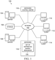
- Network data processing system 100 is a network of computers in which the advantageous embodiments may be implemented.
- Network data processing system 100 contains network 102, which is the medium used to provide communications links between various devices and computers connected together within network data processing system 100.
- Network 102 may include connections, such as wire, wireless communication links, or fiber optic cables.
- server computer 104 and server computer 106 connect to network 102 along with storage unit 108.
- client computers 110, 112, and 114 connect to network 102.
- Client computers 110, 112, and 114 may be, for example, personal computers or network computers.
- server computer 104 provides information, such as boot files, operating system images, and applications to client computers 110, 112, and 114.
- Client computers 110, 112, and 114 are clients to server computer 104 in this example.
- Network data processing system 100 may include additional server computers, client computers, and other devices not shown.
- Program code located in network data processing system 100 may be stored on a computer recordable storage medium and downloaded to a data processing system or other device for use.
- program code may be stored on a computer recordable storage medium on server computer 104 and downloaded to client computer 110 over network 102 for use on client computer 110.
- network data processing system 100 is the Internet with network 102 representing a worldwide collection of networks and gateways that use the Transmission Control Protocol/Internet Protocol (TCP/IP) suite of protocols to communicate with one another.
- TCP/IP Transmission Control Protocol/Internet Protocol
- At the heart of the Internet is a backbone of high-speed data communication lines between major nodes, or host computers, consisting of thousands of commercial, governmental, educational, and other computer systems that route data and messages.
- network data processing system 100 also may be implemented as a number of different types of networks, such as, for example, an intranet, a local area network (LAN), or a wide area network (WAN).
- LAN local area network
- WAN wide area network
- Microgrid control center 116 is a workstation that manages, control, and monitors the elements in microgrid 118.
- microgrid control center 116 is located remotely from microgrid 118.
- microgrid control center 116 may be located locally to microgrid 118.
- Microgrid 118 is an electric energy generation network having set of distributed energy resources 120.
- Set of distributed energy resources 120 is a set of one or more distributed energy resources.
- a distributed energy resource may be a small scale power generation element, such as, without limitation, a wind turbine, photovoltaic system, a fuel cell, a geothermal power generator, microturbine, combustion turbine, reciprocating engine, hybrid system, combined heat and power, or a hydroelectric power generator.
- a small scale power generation element such as, without limitation, a wind turbine, photovoltaic system, a fuel cell, a geothermal power generator, microturbine, combustion turbine, reciprocating engine, hybrid system, combined heat and power, or a hydroelectric power generator.
- Figure 1 is intended as an example, and not as an architectural limitation for the different illustrative embodiments.
- the different embodiments recognize and take into account a number of different considerations. For example, the different embodiments recognize and take into account that current microgrid power systems are centralized and face increasing challenges from the number of control variables and the complexity of the microgrid system due to changes to dynamic environments. The embodiments recognize that current, centralized microgrid control systems require software that is increasingly complex and extended in size due to the complex and dynamic environments of these systems.
- the different embodiments recognize and take into account that distributed energy resources in a microgrid reduces the amount of energy lost in transmission by generating power at or near where the power is used. This reduces the size and number of power lines.
- distributed energy resources are smaller scale power generation resources that frequently utilizes renewable energy sources.
- the different embodiments also recognize and take into account that current microgrid control systems have accessibility which requires only a tier wall of security to overcome. This creates security risks and vulnerability to hackers and other security breaches.
- the different embodiments recognize and take into account that it would be advantageous to provide a robust microgrid control system that increases the use of renewable energy sources, distributed generation, energy storage, and power quality with uninterruptible power supply and network health management capabilities.
- the different embodiments also recognize and take into account that it would be advantageous to provide a microgrid control system with cyber security at multiple levels to provide additional security.
- a first configuration of a microgrid having a set of microgrid elements is initialized.
- the set of microgrid elements is a set having two or more microgrid elements.
- the set of microgrid elements may include, without limitation, distributed energy resource sensor(s), distributed energy resource controller element(s), processor(s), and network element(s).
- a network element may include, without limitation, router(s), server(s), and distributed energy resource (s) .
- An Internet protocol address for each element in the set of microgrid elements of the microgrid may be verified.
- An average load and a common load associated with the set of microgrid elements may be then identified.
- the status data is data indicating the health of a microgrid element, a load associated with a distributed energy resource, a state of a microgrid element.
- the status data indicating a load associated with a distributed energy resource may describe a power demand at a given time, electric power output at a given time, an amount of electric power in battery storage, and/or power generation efficiency over a given period of time.
- the set of microgrid elements is re-aligned to form a second grid configuration.
- the term re-align refers to changing one or more task(s) associated with a microgrid element, changing a load associated with a distributed energy resource, and/or changing relationships between elements and distributed energy resources within a microgrid to create a new configuration.
- Re-aligning the set of elements may include changing a set of tasks to be performed by a given element, re-designating a function of a given element, or activating a redundant element to replace a failed element.
- re-aligning a set of microgrid elements may include changing a master processor to a slave processor, changing a slave processor to a master processor, increasing a load on a given distributed energy resource, decreasing a load on a given distributed energy resource, adding a distributed energy resource to the microgrid, removing a distributed energy resource from the microgrid, adding a controller element to the microgrid, removing or replacing a controller element, re-assigning a function of a first controller element to a second controller element, or any other change in the tasks and relationships between microgrid elements.
- the second grid configuration is executed to enable the microgrid to continue producing power using the re-aligned set of elements in the second grid configuration. For example, if re-aligning the set of elements included assigning a first processor to act as a master processor and a second processor to act as a slave processor, when the second grid configuration is executed, the first processor begins performing the tasks associated with the master processor and the second processor begins performing the tasks assigned to the slave processor.
- Microgrid 200 is a localized grouping of electricity generating resources and loads within power generation environment 201.
- Microgrid 200 may be a microgrid, such as, without limitation, microgrid 118 in Figure 1 .
- Microgrid 200 comprises one or more distributed energy resources, such as, without limitation, distributed energy resources (DERs) 202, 204, 206 and 208.
- distributed energy resources DERs
- microgrid 200 is connected to four distributed energy resources, however, microgrid 200 may be connected to only a single distributed energy resource, two distributed energy resources, three distributed energy resources, as well as, five or more distributed energy resources.
- Distributed energy resources 202, 204, 206, and 208 may be implemented as any type of distributed energy resources.
- microgrid 200 comprises wind turbine(s), photovoltaic cell(s), energy storage resource(s), and diesel generator(s).
- microgrid 200 may also be implemented using any other type of known or available distributed energy resources.
- microgrid 200 may optionally also be connected to a central utility.
- Each distributed energy resource on microgrid 200 can be installed or disconnected without interrupt to microgrid 200 performances and/or power output.
- Each distributed energy resource on microgrid 200 is autonomous.
- Each distributed energy resource integrated into microgrid 200 has the ability to collaborate and/or communicate with other microgrid elements to perform specific tasks.
- Microgrid 200 comprises set of controller elements 209.
- set refers to one or more items, unless defined otherwise herein.
- set of controller elements 209 is a set of one or more controller elements.
- set of controller elements 209 may include a single controller element, as well as, two or more controller elements.
- a controller element in set of controller elements 209 may be a distributed energy resource controller, a sensor, or a network element.
- a controller element may be, without limitation, a charge controller, a switch, an inverter, a router, a server, a processor, a voltage monitor, an ampere monitor, a load bank, a distributed energy resource control panel, a battery bank control, automatic transfer switch, router, processor, Ethernet switch, or universal protocol converter.
- set of controller elements 209 includes without limitation, set of photovoltaic (PV) switches 210, combiner 212, inverter 214, wind turbine (WT) charge controller 216,and PC server 218.
- Set of controller elements 209 may also include Internet router 220.
- microgrid controller elements shown in Figure 2 are only examples of some possible controller elements that may be included in microgrid 200. Microgrid 200 may not include all of the controller elements shown in Figure 2 . Likewise, microgrid 200 may include other additional controller elements not shown in Figure 2 .
- Microgrid local area network 222 is a local area network connecting the set of controller elements in microgrid 200.
- microgrid local area network 222 connects distributed energy resources 202, 204, 206, and 208 with the controller elements having an internet protocol (IP) address in a peer-to-peer network within microgrid local area network 222.
- IP internet protocol
- microgrid local area network 222 permits each controller element in microgrid 200 to transmit status information for that controller element to other controller elements on microgrid 200.
- a user at a remote client may connect to microgrid local area network 222 and obtain status and/or load information associated with distributed energy resources and controller elements on microgrid 200 by connecting to microgrid local area network 222 through internet router 220.
- Internet router 220 provides a single, common redundant network port. In other words, Internet router 220 acts as a gate controlling remote Internet access to microgrid local area network 222 and any components connected to microgrid local area network 222.
- a set of cyber-security methods and tools may be applied to Internet router 220.
- a set of cyber-security methods and tools may be implemented on the single, redundant network port at Internet router 220.
- the set of cyber-security methods and tools may be a set having a single cyber-security method and/or tool, as well as a set having multiple different cyber-security methods and tools.
- the cyber-security methods and tools in set of cyber-security methods and tools may include any known or available cyber-security method and/or cyber-security tool that is currently available or may become available in future.
- Internet router 220 provides a single point of access to microgrid local area network 222 that only permits a remote client to obtain limited information and/or access to microgrid local area network 222, such as status data and/or load data.
- the remote client may be a client connecting to microgrid local area network 222 from wide area network 224, such as the Internet.
- microgrid elements of microgrid 200 may be tied to microgrid local area network 222.
- the microgrid elements of this architecture cannot access the Internet except through microgrid internet router 220, which is a common redundant port controlled by microgrid local area network 222.
- Internet access to microgrid local area network 222 may be encrypted and secured.
- a user accessing microgrid local area network 222 from the Internet can only access status data and load measurement information.
- Microgrid 200 has a distributed architecture that may utilize cyber security at every tier or level of controllability.
- Microgrid control center 226 is a control work station within power generation environment 201 that monitors the health and status of controller elements and distributed energy resources associated with microgrid 200.
- Microgrid control center 226 may be implemented as a microgrid control center, such as microgrid control center 116 in Figure 1 .
- Microgrid control center 226 monitors the health and status of microgrid elements by receiving status data 228 from each microgrid element in real-time. Status data 228 indicates the power output by distributed energy resource(s) on microgrid 200, power demands on microgrid 200, and the functional or operational status of microgrid elements.
- the load associated with the first distributed energy resource may be re-assigned to a second distributed energy resource. For example, if a photovoltaic cell(s) produces less energy than expected due to an overcast, cloudy sky, the load for that photovoltaic cell(s) can be shifted to a wind turbine or a diesel generator.
- microgrid 200 can be re-configured to compensate for changes in performance, output or function of individual elements of microgrid 200 with little or no disruption to the overall function, performance, and power output produced by microgrid 200.
- FIG 2 is intended as an example, and not as an architectural limitation for the different advantageous embodiments.
- microgrid control center 226 is depicted as being located remotely to microgrid 200.
- microgrid control center 226 may be located locally to microgrid 200.
- power generation environment 201 comprises a microgrid and a microgrid control center 226.
- power generation environment 201 may also include an electric power utility macrogrid.
- microgrid 200 may be connected to and/or slaved to the electric power utility macrogrid.
- FIG. 3 is an illustration of a microgrid control center in accordance with an example that is useful for understanding the disclosure.
- Microgrid control center 300 is a workstation that manages a microgrid.
- Microgrid control center 300 may include microgrid controller 302, database 304, and router 306.
- Microgrid controller 302 is a data processing system that configures distributed energy resources and controller elements in a microgrid, monitors the status and loads associated with the distributed energy resources and controller elements in the microgrid, and re-aligns the controller elements to compensate for element failures.
- Database 304 is a redundant database for data storage associated with managing the microgrid.
- database 304 may be implemented as a database located on redundant array of independent disks (RAID).
- Database 304 may be rack mounted.
- Router 306 in this example is a network router that establishes a first level network between microgrid control center 300 and the distributed energy resources in the microgrid.
- Distributed energy resource clusters 308, 309, and 310 are clusters of one or more distributed energy resources associated with the microgrid.
- the microgrid includes three distributed energy resource clusters.
- the microgrid may include any number of distributed energy resource clusters, such as a single distributed energy resource cluster, two distributed energy resource clusters, as well as four or more distributed resource clusters
- the set of controller elements 312, 313, and 314 is a set having at least one of a distributed energy resource sensor, a distributed energy resource controller, and a local area network element associated with the microgrid.
- the phrase "at least one of”, when used with a list of items, means that different combinations of one or more of the listed items may be used and only one of each item in the list may be needed.
- "at least one of item A, item B, and item C" may include, for example, without limitation, item A or item A and item B. This example also may include item A, item B, and item C or item B and item C.
- Network 316 is a microgrid controller network connecting microgrid control center 300 with the microgrid local area network connecting the distributed energy resources and controller elements.
- Network 316 in this example is a wide area network connecting a remote microgrid control center 300 with the microgrid.
- network 316 may connect a local microgrid controller and local database with the microgrid local area network.
- network 316 may be a microgrid control center network utilizing transmission control protocol/internet protocol (TCP/IP) and user datagram protocol (UDP).
- TCP/IP transmission control protocol/internet protocol
- UDP user datagram protocol
- Microgrid control process 318 is a process by which microgrid controller 302 utilizes network 316 to initialize the microgrid system, configure the distributed energy resources and controller elements, determine the average load and local loads associated with the microgrid elements, and monitor the status of microgrid elements.
- microgrid control process 318 identifies a threshold level of change associated with a microgrid controller element or load, control process 318 initiates reconfigurations and/or re-alignments of microgrid elements and resources as necessary to compensate and permit uninterrupted power supply to end users.
- a threshold level of change associated with a microgrid element may occur due to a controller element failure, an increase in power demand, or a decrease in power production from one or more distributed energy resources.
- the microgrid may also include multiple tiers of cyber security.
- the microgrid shown in Figure 3 may include multiple tiers of cyber security at every level of controllability, including, but not limited to, cyber security at the microgrid control center 300 level, cyber security at the distributed energy resource cluster 308-310 level, and cyber security at the controller element level.
- Figure 3 is intended as an example, and not as an architectural limitation for the different embodiments.
- FIG. 4 an illustration of a distributed energy resource cluster is shown in accordance with an embodiment.
- Distributed energy resource cluster 400 is a grouping of one or more distributed energy resources. Each distributed energy resource cluster in the microgrid has at least one processor associated with the distributed energy resource cluster. In this example, distributed energy resource cluster 400 is a grouping of one or more distributed energy resource s associated with processor 402.
- Processor 402 may be either a master processor or a slave processor.
- a master processor may be re-designated as a slave processor as needed.
- a slave processor may be re-designated as a master processor.
- the master processor may synchronize microgrid elements and/or provide a robust power bus with no down times.
- a distributed energy resource processor may manage elements in distributed energy resource cluster 400, such as controller elements, network elements, and distributed energy resources
- processor 402 may have the ability to control photovoltaic combiner switch(es), photovoltaic panel(s), direct current bus switch(es), wind turbine charge regulator(s), power inverter(s) and power regulator(s).
- Processor 402 may have the ability to measure energy harvest, maximize direct current power generation, maximize energy storage, prioritize loads, assign shared loads to slave elements, and synchronize electricity generated with the power interface voltage and/or frequency.
- Processor 402 may have the ability to control energy harvest and load shedding.
- Processor 402 may also have the ability to maintain power quality on linear and non-linear loads, adjust local load demand, and configure local setup procedures and system initial configuration.
- processor network 404 is a peer-to-peer network connecting two or more distributed energy resource cluster processors in the microgrid, such as processor 402, together in a peer-to-peer network.
- processor network 404 connects processor 402 of distributed energy resource cluster 400 with the processor associated with distributed energy resource cluster 406 and distributed energy resource cluster 408.
- Processor network 404 enables processor 402 to exchange status information, load information, and other data with distributed energy resource clusters 406 and 408, as well as any other distributed energy resource clusters on the microgrid having a processor connected to processor network 404.
- Controller elements 410, 412, 414, and 416 are distributed energy resource sensors and controllers associated with distributed energy resource cluster 400. Controller elements 410, 412, 414, and 416 may be any type of distributed energy resource sensors and controllers, such as, but without limitation, an inverter, volt/amp monitor, automatic transfer switch, load bank, battery bank control, distributed energy resource control panel, a charge controller, or any other type of controller, sensor, or network element.
- Controller elements 410, 412, 414, and 416 are connected together in a peer-to-peer controller network 418.
- Controller network 418 may be a redundant ring network using the transmission control protocol/internet protocol and user datagram protocol protocols.
- the ring network may be an Ethernet network.
- a redundant ring network disables one leg of the ring when a failure occurs.
- the redundant ring may function as a C-ring.
- Controller network 418 comprises switches 420, 422, 424, 426, 428, 430, and 432. Each switch in controller network 418 connects to exactly two other switches to from a continuous pathway for signals through each managed Ethernet switch.
- switches 420, 422, 424, 426, 428, 430, and 432 are, without limitation, managed Ethernet switches.
- Switches may be dedicated Internet network (DIN) rail mounted components.
- the processors, such as processor 402, may also optionally be dedicated Internet network rail mounted.
- Controller network 418 may utilize a counter-rotating ring to form a redundant ring network topology.
- a single leg failure between two Ethernet switches causes only a small initial delay in controller network 418 at the time of the Ethernet switch failure.
- Each controller element that requires access to network processors on processor network 404 is connected to a managed Ethernet switch in distributed energy resource cluster 400. If a managed Ethernet switch fails, all controller elements connected to that Ethernet switch are isolated from the network.
- every managed Ethernet switch is connected to a single controller element in distributed energy resource cluster 400.
- each controller element is connected to its own Ethernet switch in controller network 418.
- a managed Ethernet switch may be connected to two or more controller elements.
- Each controller element connected to an Ethernet switch may use the transmission control protocol/internet protocol and user datagram protocol interface protocol.
- a controller element may be connected to a protocol converter to convert the protocol of the controller element into the protocol of the Ethernet switches.
- controller elements 410, 412, 414, and 416 and their associated Ethernet switches 420, 422, 424, and 426 are connected to a universal protocol converter, such as universal protocol converters 434, 436, 438, 440, and 442.
- Universal protocol converters 434, 436, 438, 440, and 442 convert the protocols used by the controller elements into the protocol used by the managed Ethernet switches.
- Universal protocol converters 434, 436, 438, 440, and 442 also convert the protocol used by a given Ethernet switch into the protocol used by the controller element connected to that given Ethernet switch.
- Routers 444 and 446 may be implemented as one or more router devices that interconnect controller network 418 with processor network 404. Routers 444 and 446 may also be utilized to connect control center network 448 with processor network 404 and controller network 418.
- Control center network 448 is a top level network connecting microgrid control center 450 with the microgrid processor network 404.
- Microgrid control center 450 is a workstation for configuring the microgrid and monitoring the health of the distributed energy resources associated with the microgrid, such as microgrid control center 116 in Figure 1 , microgrid control center 226 in Figure 2 , and 300 in Figure 3 .
- Control center network 448 , processor network 404 , and controller network 418 is the microgrid control, communications, and command network for monitoring, controlling, configuring, and re-configuring microgrid elements.
- Each of control center network 448, processor network 404, and controller network 418 may have a ring topology using managed Ethernet switches. In this manner, any open network line or failed Ethernet switch will not have a negative impact on operation of the remainder of the microgrid elements.
- Any processor can obtain status data from any controller element, distributed energy resource, or other processor connected to the peer-to-peer network.
- the distributed energy resource cluster processors, control center network 448, processor network 404, and controller network 418 reduce the complexity of a microgrid control system by providing the network elements the intelligence and communication capabilities with one or more other microgrid elements.
- each microgrid element to know the state of its subsystem or load its controls. This information is communicated to other microgrid elements, which makes the status of neighboring systems within the microgrid known to each distributed energy resource cluster. In this manner, the distributed energy generation and storage capabilities of the microgrid system are increased. Likewise, a single microgrid element failure will not disable or prevent other microgrid elements from operating.
- control center network 448, controller network 418, and processor network 404 enable the transfer of information between distributed energy resources, microgrid control center 450, processors, and external communication links.
- a set of cyber security methods and tools may be implemented at multiple different levels of the microgrid shown in Figure 4 .
- cyber security methods and tools may be implemented on a level associated with at least one of an individual controller element 410, a set of controller elements, all controller elements associated with a distributed energy resource, an individual distributed energy resource, a given distributed energy resource cluster, processor 402, microgrid control center 450, processor network 404, controller network 418, control center network 448, or any other level of a distributed microgrid architecture.
- cyber security may be implemented within multiple different levels using multiple different cyber security methods and/or tools.
- Figure 4 is intended as an example, and not as an architectural limitation for the different advantageous embodiments.
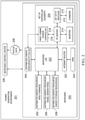
- Data processing system 500 may be a data processing system associated with a microgrid control center.
- Data processing system 500 may be associated with one or more distributed energy resources, controller elements, or control center in a microgrid or power generation environment.
- microgrid control center 116 in Figure 1 microgrid control center 226 in Figure 2
- PC server 218 in Figure 2 microgrid controller 302 in Figure 3
- processor 402 in Figure 4 and/or microgrid control center 450 in Figure 4 may be implemented using data processing system 500.
- data processing system 500 includes communications fabric 502, which provides communications between processor unit 504, memory 506, persistent storage 508, communications unit 510, input/output (I/O) unit 512, and display 514.
- communications fabric 502 provides communications between processor unit 504, memory 506, persistent storage 508, communications unit 510, input/output (I/O) unit 512, and display 514.
- Processor unit 504 serves to execute instructions for software that may be loaded into memory 506.
- Processor unit 504 may be a number of processors, a multi-processor core, or some other type of processor, depending on the particular implementation.
- a number, as used herein with reference to an item, means one or more items.
- processor unit 504 may be implemented using a number of heterogeneous processor systems in which a main processor is present with secondary processors on a single chip.
- processor unit 504 may be a symmetric multi-processor system containing multiple processors of the same type.
- Memory 506 and persistent storage 508 are examples of storage devices 516.
- a storage device is any piece of hardware that is capable of storing information, such as, for example, without limitation, data, program code in functional form, and/or other suitable information either on a temporary basis and/or a permanent basis.
- Storage devices 516 may also be referred to as computer readable storage devices in these examples.
- Memory 506, in these examples, may be, for example, a random access memory or any other suitable volatile or nonvolatile storage device.
- Persistent storage 508 may take various forms, depending on the particular implementation.
- persistent storage 508 may contain one or more components or devices.
- persistent storage 508 may be a hard drive, a flash memory, a rewritable optical disk, a rewritable magnetic tape, or some combination of the above.
- the media used by persistent storage 508 also may be removable.
- a removable hard drive may be used for persistent storage 508.
- Communications unit 510 in these examples, provides for communications with other data processing systems or devices.
- communications unit 510 is a network interface card.
- Communications unit 510 may provide communications through the use of either or both physical and wireless communications links.
- Input/output unit 512 allows for input and output of data with other devices that may be connected to data processing system 500.
- input/output unit 512 may provide a connection for user input through a keyboard, a mouse, and/or some other suitable input device. Further, input/output unit 512 may send output to a printer.
- Display 514 provides a mechanism to display information to a user.
- Instructions for the operating system, applications, and/or programs may be located in storage devices 516, which are in communication with processor unit 504 through communications fabric 502. In these illustrative examples, the instructions are in a functional form on persistent storage 508. These instructions may be loaded into memory 506 for execution by processor unit 504. The processes of the different embodiments may be performed by processor unit 504 using computer implemented instructions, which may be located in a memory, such as memory 506.
- program code computer usable program code
- computer readable program code that may be read and executed by a processor in processor unit 504.
- the program code in the different embodiments may be embodied on different physical or computer readable storage media, such as memory 506 or persistent storage 508.
- Program code 518 is located in a functional form on computer readable media 520 that is selectively removable and may be loaded onto or transferred to data processing system 500 for execution by processor unit 504.
- Program code 518 and computer readable media 520 form computer program product 522 in these examples.
- computer readable media 520 may be computer readable storage media 524 or computer readable signal media 526.
- Computer readable storage media 524 may include, for example, an optical or magnetic disk that is inserted or placed into a drive or other device that is part of persistent storage 508 for transfer onto a storage device, such as a hard drive, that is part of persistent storage 508.
- Computer readable storage media 524 also may take the form of a persistent storage, such as a hard drive, a thumb drive, or a flash memory, that is connected to data processing system 500. In some instances, computer readable storage media 524 may not be removable from data processing system 500. In these illustrative examples, computer readable storage media 524 is a non-transitory computer readable storage medium.
- program code 518 may be transferred to data processing system 500 using computer readable signal media 526.
- Computer readable signal media 526 may be, for example, a propagated data signal containing program code 518.
- Computer readable signal media 526 may be an electromagnetic signal, an optical signal, and/or any other suitable type of signal. These signals may be transmitted over communications links, such as wireless communications links, optical fiber cable, coaxial cable, a wire, and/or any other suitable type of communications link.
- the communications link and/or the connection may be physical or wireless in the illustrative examples.
- program code 518 may be downloaded over a network to persistent storage 508 from another device or data processing system through computer readable signal media 526 for use within data processing system 500.
- program code stored in a computer readable storage medium in a server data processing system may be downloaded over a network from the server to data processing system 500.
- the data processing system providing program code 518 may be a server computer, a client computer, or some other device capable of storing and transmitting program code 518.
- the different components illustrated for data processing system 500 are not meant to provide architectural limitations to the manner in which different embodiments may be implemented.
- the different advantageous embodiments may be implemented in a data processing system including components in addition to or in place of those illustrated for data processing system 500.
- Other components shown in Figure 5 can be varied from the illustrative examples shown.
- the different embodiments may be implemented using any hardware device or system capable of running program code.
- the data processing system may include organic components integrated with inorganic components and/or may be comprised entirely of organic components excluding a human being.
- a storage device may be comprised of an organic semiconductor.
- processor unit 504 may take the form of a hardware unit that has circuits that are manufactured or configured for a particular use. This type of hardware may perform operations without needing program code to be loaded into a memory from a storage device to be configured to perform the operations.
- processor unit 504 when processor unit 504 takes the form of a hardware unit, processor unit 504 may be a circuit system, an application specific integrated circuit (ASIC), a programmable logic device, or some other suitable type of hardware configured to perform a number of operations.
- ASIC application specific integrated circuit
- a programmable logic device the device is configured to perform the number of operations. The device may be reconfigured at a later time or may be permanently configured to perform the number of operations.
- Examples of programmable logic devices include, for example, a programmable logic array, programmable array logic, a field programmable logic array, a field programmable gate array, and other suitable hardware devices.
- program code 518 may be omitted because the processes for the different embodiments are implemented in a hardware unit.
- processor unit 504 may be implemented using a combination of processors found in computers and hardware units.
- Processor unit 504 may have a number of hardware units and a number of processors that are configured to run program code 518. With this depicted example, some of the processes may be implemented in a number of hardware units, while other processes may be implemented in a number of processors.
- a storage device in data processing system 500 is any hardware apparatus that may store data.
- Memory 506, persistent storage 508, and computer readable media 520 are examples of storage devices in a tangible form.
- a bus system may be used to implement communications fabric 502 and may be comprised of one or more buses, such as a system bus or an input/output bus.
- the bus system may be implemented using any suitable type of architecture that provides for a transfer of data between different components or devices attached to the bus system.
- a communications unit may include one or more devices used to transmit and receive data, such as a modem or a network adapter.
- a memory may be, for example, memory 506, or a cache, such as found in an interface and memory controller hub that may be present in communications fabric 502.
- Figure 5 is intended as an example, and not as an architectural limitation for the different advantageous embodiments.
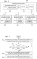
- FIG. 6 is an illustration of a flowchart of a process for configuring a microgrid in accordance with an example useful for understanding the disclosure.
- the process illustrated in Figure 6 may be implemented in a control center for a microgrid, such as microgrid control system 116 in Figure 1 , microgrid control center 226 in Figure 2 , microgrid control center 300 in Figure 3 , and/or microgrid control center 450 in Figure 4 .
- this process may be implemented using control process 318 running on microgrid controller 302 in Figure 3 .
- the process shown in Figure 6 begins by initializing a default configuration for each element in a set of microgrid elements (operation 602).
- the set of microgrid elements may include, without limitation, sensor elements associated with distributed energy resource(s), controller elements associated with distributed energy resource(s), and network elements.
- Operation 602 may include setting a default configuration for each element and verifying that the microgrid local area network is secure. In another embodiment, operation 602 may also include the power-up sequence of the entire microgrid system or the power-up sequence for a given distributed energy resource.
- the process verifies an Internet protocol address for each element in the set of elements of the microgrid (operation 604).
- the process may configure or assign Internet protocol addresses to one or more elements at operation 604. In other words, the process verifies network membership of the microgrid elements.
- the process pings each element in the set of elements (operation 606).
- Operation 606 pings each element to verify the configuration of microgrid elements.
- the process determines a grid configuration (operation 608) based on the results of pinging each element if the microgrid is already operational. If the microgrid is not yet operational with an existing configuration, operation 608 generates a microgrid configuration. In other words, the process at operation 608 creates or selects a configuration for the microgrid.
- the process assigns a master processor and slave processor(s) (operation 610).
- the master processor controls the microgrid systems and/or subsystems. All other distributed resource processors are slaved to the master processor.
- operation 612 identifies the processor associated with a distributed energy resource or distributed energy resource cluster that is associated with the primary load to be designated as the master processor.
- the processors associated with other distributed energy resources or distributed energy resource clusters are designated slave processors to the master processor.
- the process makes a determination as to whether the microgrid is a utility tied microgrid (operation 612). If the utility is not a utility tied microgrid, the process executes operation 616. If the microgrid is connected to a utility, the process synchronizes the microgrid with the utility (operation 614). In other words, the microgrid power output is slaved to the utility.
- Operation 616 determines an average alternating current (AC) bus loading (operation 616). Operation 616 may also determine transmission line impedances.
- AC alternating current
- the process identifies local loads for each distributed energy resource connected to the microgrid (operation 618).
- the process at operation 618 may also determine the criticality of local loads for each distributed energy resource.
- the process receives status data from the set of elements connected in a peer-to-peer network within a microgrid local area network (operation 620).
- the status data may be received as a result of performing a state of health test for one or more elements in the set of microgrid elements.
- a state of health test is performed on every element in the set of microgrid elements.
- the process makes a determination as to whether a realignment of microgrid elements is indicated based on the status data (operation 622). If the status data indicates a reconfiguration, the process re-aligns the set of elements to form a second grid configuration (operation 624). Re-aligning the set of elements may include changing a set of tasks to be performed by a given element, re-designating a function of a given element, or activating a redundant element to replace a failed element.
- the process executes the grid configuration (operation 626).
- the process continues to monitor the microgrid system (operation 628) in real-time.
- the process then returns to operation 620 if the monitored status data indicates a grid reconfiguration.
- the status data may indicate a grid re-configuration if the status indicates a failure in an element in the microgrid, a decrease in power output by a distributed energy resource, an increase in power demand, or any other status change.
- FIG. 7 an illustration of a flowchart of a process for configuring a microgrid is depicted in accordance with an embodiment.
- the process illustrated in Figure 7 may be implemented in a control center for a microgrid, such as microgrid control system 116 in Figure 1 , microgrid control center 226 in Figure 2 , microgrid control center 300 in Figure 3 , and/or microgrid control center 450 in Figure 4 .
- this process may be implemented using control process 318 running on microgrid controller 302 in Figure 3 .
- the process in Figure 7 may also be implemented by a master processor in a microgrid, such as processor 402 in Figure 4 .
- the process begins by receiving status data from a set of microgrid controller elements connected in a peer-to-peer network on a microgrid (operation 702).
- the process makes a determination as to whether a status change exceeds a threshold level (operation 704) .
- the process returns to operation 702 and continues monitoring the status of the microgrid. If the change in status does not exceed a threshold level, the process returns to operation 702 and continues monitoring the status of the microgrid. If the change does exceed the threshold level of change, the process re-aligns the set of microgrid controller elements to form a re-aligned microgrid configuration (operation 706). The process executes the re-aligned microgrid configuration (operation 708). The process returns to operation 702 to continue monitoring the status of the microgrid.
- each block in the flowchart or block diagrams may represent a module, segment, function, and/or a portion of an operation or step.
- one or more of the blocks may be implemented as program code, in hardware, or a combination of the program code and hardware.
- the hardware may, for example, take the form of integrated circuits that are manufactured or configured to perform one or more operations in the flowcharts or block diagrams.
- the function or functions noted in the block may occur out of the order noted in the figures.
- two blocks shown in succession may be executed substantially concurrently, or the blocks may sometimes be executed in the reverse order, depending upon the functionality involved.
- other blocks may be added in addition to the illustrated blocks in a flowchart or block diagram.
- a method for configuring a microgrid.
- a first configuration of a microgrid having a set of microgrid elements is initialized.
- An Internet protocol address for each element in the set of elements of the microgrid is verified.
- An average load and a common load associated with the set of elements is identified.
- Status data from the set of elements connected in a peer-to-peer network within a microgrid local area network is received.
- the set of elements is re-aligned to form a second grid configuration.
- the second grid configuration is executed.
- the different embodiments provide an adaptable microgrid control system that provides microgrid elements with portability, re-configurability, and standardization for all microgrid systems and components firmware.
- the microgrid control system of the advantageous embodiments provides a control system that increases the reliability, utilization, and efficiency of renewable energy sources, distributed energy generation, distributed energy storage, and power quality with predictable, uninterrupted power supply to end users.
- the embodiments also provide a microgrid control system with network health monitoring capabilities and adaptability to compensate for element failures, decreases in energy production from a distributed energy resource, and increases in energy demand from end users.
- the different embodiments also provide a microgrid control architecture and communications network that increases the use of renewable energy sources, distributed energy generation, power storage, and power quality.
- the microgrid control system of the advantageous embodiments also provides uninterruptible power supply and network health management capabilities.
- the embodiments also provide a microgrid control system with portability, re-configurability, and standardization for all of the microgrid systems, elements, and components firmware.
- the microgrid control system of the embodiments may also be utilized to enable distributed intelligence that reduces the complexity of power system operation by assigning control functions locally at lower levels rather than at a centralized control center. Moreover, the microgrid control system of the embodiments may provide distributed power generation that is redundant, resilient, and has a secure infrastructure.
- the different embodiments can take the form of an entirely hardware embodiment, an entirely software embodiment, or an embodiment containing both hardware and software elements.
- Some embodiments are implemented in software, which includes but is not limited to forms, such as, for example, firmware, resident software, and microcode.
- the different embodiments can take the form of a computer program product accessible from a computer usable or computer readable medium providing program code for use by, or in connection with, a computer, or any device or system that executes instructions.
- a computer usable or computer readable medium can generally be any tangible apparatus that can contain, store, communicate, propagate, or transport the program for use by or in connection with the instruction execution system, apparatus, or device.
- the computer usable or computer readable medium can be, for example, without limitation, an electronic, magnetic, optical, electromagnetic, infrared, or semiconductor system, or a propagation medium.
- a computer readable medium include a semiconductor or solid state memory, magnetic tape, a removable computer diskette, a random access memory (RAM), a read-only memory (ROM), a rigid magnetic disk, and an optical disk.
- Optical disks may include compact disk - read only memory (CD-ROM), compact disk - read/write (CD-R/W), and DVD.
- a computer usable or computer readable medium may contain or store a computer readable or usable program code, such that when the computer readable or usable program code is executed on a computer, the execution of this computer readable or usable program code causes the computer to transmit another computer readable or usable program code over a communications link.
- This communications link may use a medium that is, for example without limitation, physical or wireless.
- a data processing system suitable for storing and/or executing computer readable or computer usable program code may include one or more processors coupled directly or indirectly to memory elements through a communications fabric, such as a system bus.
- the memory elements may include local memory employed during actual execution of the program code, bulk storage, and cache memories which provide temporary storage of at least some computer readable or computer usable program code to reduce the number of times code may be retrieved from bulk storage during execution of the code.
- I/O devices can be coupled to the system either directly or through intervening I/O controllers. These devices may include, for example, without limitation, keyboards, touch screen displays, and pointing devices. Different communications adapters may also be coupled to the system to enable the data processing system to become coupled to other data processing systems or remote printers or storage devices through intervening private or public networks. Modems and network adapters are just a few of the non-limiting examples currently available types of communications adapters.
- More illustrative embodiments may include an apparatus , wherein the microgrid controller is further configured to perform a live test of the first configuration, wherein the live test comprises pinging the each element in the set of microgrid elements.
- More illustrative embodiments may include an apparatus , wherein the peer-to-peer network is a network within a microgrid local area network and further comprising: a set of controller elements, wherein the peer-to-peer network further comprises a controller network connecting each element in the set of controller elements to form a peer-to-peer controller network within the microgrid local area network
- More illustrative embodiments may include an apparatus further comprising: a first controller element in the set of controller elements, wherein the first controller element is configured to send controller status data generated by the first controller element to a second controller element in the set of microgrid controller elements using the controller network.
- More illustrative embodiments may include an apparatus , wherein the peer-to-peer network is a network within a microgrid local area network and further comprising: a set of processors, wherein the peer-to-peer network comprises a processor network connecting each distributed energy resource processor in the set of processors to form a peer-to-peer processor network within the microgrid local area network.
- More illustrative embodiments may include an apparatus further comprising: a first processor in the set of processors configured to send processor status data generated by the first processor to a second processor in the set of processors using the processor network.
- More illustrative embodiments may include an apparatus further comprising: a single common redundant network port for Internet access to a microgrid local area network, wherein a remote client can access the microgrid local area network through the single common redundant network port, , wherein a set of cyber-security methods and tools are implemented on the single, common redundant network port; and wherein the single common redundant network port is configured to permit remote clients access to status data and deny remote clients access to control functions associated with the microgrid.
- More illustrative embodiments may include a computer program product, wherein the peer-to-peer network is a network within a microgrid local area network and wherein the peer-to-peer network further comprises a controller network and further comprising:
- More illustrative embodiments may include a computer program product, wherein the peer-to-peer network is a network within a microgrid local area network, wherein the peer-to-peer network further comprises a processor network connecting each distributed energy resource processor in a set of cluster processors in the peer-to-peer network within the microgrid local area network, and further comprising: program code, stored on the computer recordable storage medium, for sending status data generated by a first cluster processor on the microgrid to a second cluster processor in the set of cluster processors using the processor network.
- More illustrative embodiments may include a computer program product further comprising: program code, stored on the computer recordable storage medium, for sending the status data generated by a controller element within the set of microgrid elements to a set of distributed energy resource processors on the microgrid using the peer-to-peer local area network; and program code, stored on the computer recordable storage medium, for sending the status data generated by a distributed energy cluster processor to every processor in the set of distributed energy resource.
Landscapes
- Engineering & Computer Science (AREA)
- Computer Networks & Wireless Communication (AREA)
- Signal Processing (AREA)
- Theoretical Computer Science (AREA)
- Physics & Mathematics (AREA)
- General Engineering & Computer Science (AREA)
- General Physics & Mathematics (AREA)
- General Health & Medical Sciences (AREA)
- Computing Systems (AREA)
- Health & Medical Sciences (AREA)
- Medical Informatics (AREA)
- Automation & Control Theory (AREA)
- Multimedia (AREA)
- Power Engineering (AREA)
- Computer Security & Cryptography (AREA)
- Remote Monitoring And Control Of Power-Distribution Networks (AREA)
- Supply And Distribution Of Alternating Current (AREA)
- Programmable Controllers (AREA)
- Logic Circuits (AREA)
- Arrangements For Transmission Of Measured Signals (AREA)
- Data Exchanges In Wide-Area Networks (AREA)
Description
- The present disclosure relates generally to power grids and, in particular, to a method, apparatus, and computer program product for managing microgrids. Still more particularly, the present disclosure relates to a method, apparatus, and computer program product for an adaptable microgrid robust control system.
- Currently, most electric power is generated by macrogrids. Macrogrids typically are large, centralized power plants, such as nuclear power plants, hydroelectric plants, and fossil fuel powered plants. Macrogrids commonly have good economies of scale. However, macrogrids frequently require power to be transmitted across long distances. These large facilities frequently generate power using non-renewable sources of energy, such as coal or gas. These facilities may negatively impact the environment.
- A microgrid is a localized grouping of electric power generation sources and loads. A microgrid may also be referred to as, without limitation, a smart-grid, mini-grid, or virtual power plant. However, existing microgrid control systems tend to be overly complex and under-utilize renewable resources.
- Therefore, it would be advantageous to have a method and apparatus that takes into account one or more of the issues discussed above, as well as other issues.
-
US2002/0057018A1 discloses a telecommunications network device including at least one power distribution unit capable of connecting to multiple, unregulated DC power feeds. The network device may also include a redundant power distribution unit. Both power distribution units are independently removable from the network device. Thus, when two power distribution units are mounted within the network device one may be removed for repair or upgrade and the other power distribution unit will continue to provide power to the network device such that it may continue running. Each power distribution unit may also include an on/off switch, which when in an "on" position allows the power distribution unit to supply power from each connected power feed to the network device and when in an "off" position prevents the power distribution unit from supplying power from any power feed to the network device. Thus, prior to removing the power distribution unit from the network device the on/off switch may be moved to the "off" position. - In
WO2010/003724A2 , a system and a method for implementing an electrical process controlling a Distributed Control System (DCS) is provided. The system is based on integrating Industrial Substation Automation system and the DCS by having a combined control bus conveying process control messages and station bus conveying power control messages. The integrated industrial automation system utilizes a process controller capable of communication using IEC 61850 communication standard interacts with one or more Intelligent Electronic Devices (IEDs) configured for one or more substations in an industrial plant. The method of configuring the process controller of the integrated industrial automation system uses electrical process and plant process engineering tools. The plant process engineering tool has at least one module, present as an integral part of externally for engineering IEC 61850 based application or function for configuring one or more process controllers of the integrated industrial automation system. -
US2010/0082792A1 introduces an energy efficiency solution for automatically pushing data measured by IEDs in a utility system to an Internet server. Before the utility system is commissioned, the manufacturer pre-configures each IED to automatically push measured data to the server at regular intervals and associates each IED with a unique identifier that is transmitted with the data and with a customer who has purchased the solution. After commissioning, the IEDs come online and begin to automatically push their measured data to the server. The customer logs into the website via a manufacturer-provided access code to access the measured data instantly. Requests to change the type of data pushed from IEDs and other configuration changes can be made via the website. Periodically, the IEDs ask whether any configuration updates exist, and if so, the server makes available to the IEDs the updated configuration. By having IEDs initiate communications for data transmission and configuration updates, intervening firewalls are bypassed. -
EP1976218 describes a method and system for configuring an International Electrotechnical Commission (IEC) 61850 standard-compliant Intelligent Electronic Device (IED) 104 inSA system 100. Proxy IED 104 is a NCC gateway device enhanced for converting data between non-IEC 61850 and IEC 61850 communication protocols. Proxy IED 104 is configured, based on a set of mappings, which are coded in the SA configuration description (SCD) file. The SCD file includes mappings for data conversion between non-IEC 61850 and IEC 61850 communication protocols. -
US2006/184665 describes a transmission method of network infrastructure. The method involves displaying changes in network infrastructure caused by active X-control protocol, during transmission of network infrastructure. The data for acquiring network infrastructure is collected, for transmitting the acquired infrastructure to an industrial process engineering or technology device. The changes in the infrastructure caused by an active X-control protocol during transmission of infrastructure, are displayed immediately in the technology device. The method is used for transmitting network infrastructure to industrial process engineering or technology device in manufacturing system e.g. supervisory control and data acquisition (SCDA) system for monitoring tunnels, conditions in buildings, wind-energy generating farms, electricity generation power plant, etc. - The invention to which this European patent application relates is defined in independent claims 1, 4 and 7. Optional features are defined in the dependent claims.
- In one example, a method is provided for configuring a microgrid. A first configuration of the microgrid having a set of microgrid elements is initialized. An address for each element in the set of microgrid elements of the microgrid is verified. In response to receiving status data from the set of microgrid elements connected in a peer-to-peer network indicating a reconfiguration of the microgrid, the set of microgrid elements is re-aligned to form a second grid configuration. The second grid configuration is executed.
- In an advantageous embodiment, a method for monitoring a microgrid is provided. Status data is received from a set of microgrid controller elements connected in a peer-to-peer network connecting the set of microgrid controller elements within the microgrid local area network. In response to the status data indicating a change in the microgrid that exceeds a threshold level, the set of microgrid controller elements and a set of tasks associated with the set of microgrid controller elements is re-aligned to form a re-aligned microgrid configuration. The re-aligned microgrid configuration is executed. Status data is received from a set of distributed energy resource cluster processors connected in a peer-to-peer processor network within the microgrid local area network.
- In yet another advantageous embodiment, an apparatus comprises a microgrid and a microgrid controller associated with the microgrid configured to initialize a first configuration of a microgrid having a set of microgrid elements. The microgrid controller is configured to verify an address for each element in the set of elements of the microgrid. The microgrid controller is configured to re-align the set of elements to form a second grid configuration in response to receiving status data from the set of microgrid elements connected in a peer-to-peer network indicating a reconfiguration of the microgrid. The microgrid controller is configured to execute the second grid configuration. The peer-to-peer network is a network within a local area network and the peer-to-peer network further comprises a peer-to-peer redundant ring controller network sending the status data generated by a controller element within the set of microgrid elements to a set of distributed energy resource processors on the microgrid using the peer-to-peer local area network, and a peer-to-peer processor network sending the status data generated by a distributed energy cluster processor to every processor in the set of distributed energy resource processors.
- The microgrid controller can be further configured to perform a live test of the first configuration, wherein the live test comprises pinging the each element in the set of microgrid elements.
- The peer-to-peer network can be a network within a microgrid local area network which further comprises a set of controller elements, wherein the peer-to-peer network may further comprise a controller network connecting each element in the set of controller elements to form a peer-to-peer controller network within the microgrid local area network
- The apparatus may further comprise a first controller element in the set of controller elements, wherein the first controller element is configured to send controller status data generated by the first controller element to a second controller element in the set of microgrid controller elements using the controller network.
- The peer-to-peer network may be a network within a microgrid local area network which further comprises a set of processors, wherein the peer-to-peer network comprises a processor network connecting each distributed energy resource processor in the set of processors to form a peer-to-peer processor network within the microgrid local area network.
- The first processor in the set of processors may be configured to send processor status data generated by the first processor to a second processor in the set of processors using the processor network.
- In an example useful for understanding the disclosure, the apparatus may further comprise a single common redundant network port for Internet access to a microgrid local area network, wherein a remote client can access the microgrid local area network through the single common redundant network port, wherein a set of cyber-security methods and tools are implemented on the single, common redundant network port; and wherein the single common redundant network port is configured to permit remote clients access to status data and deny remote clients access to control functions associated with the microgrid.
- The novel features believed characteristic of the advantageous embodiments are set forth in the appended claims. The advantageous embodiments, however, as well as a preferred mode of use, further objectives and advantages thereof, will best be understood by reference to the following detailed description of an advantageous embodiment of the present disclosure when read in conjunction with the accompanying drawings, wherein:
-
Figure 1 is an illustration of a data processing environment for a microgrid control system in accordance with an advantageous embodiment; -
Figure 2 is an illustration of a microgrid in accordance with an advantageous embodiment; -
Figure 3 is an illustration of a microgrid control center in accordance with an example useful for understanding the disclosure; -
Figure 4 is an illustration of a distributed energy resource cluster in accordance with an advantageous embodiment; -
Figure 5 is an illustration of a data processing system in accordance with an example useful for understanding the disclosure; -
Figure 6 is an illustration of a flowchart of a process for managing a microgrid in accordance with an example useful for understanding the disclosure; and -
Figure 7 is an illustration of a flowchart of a process for configuring a microgrid in accordance with an advantageous embodiment. - With reference now to the figures and in particular with reference to
Figure 1 , it depicts a pictorial representation of a network of data processing systems in which different embodiments may be implemented. Networkdata processing system 100 is a network of computers in which the advantageous embodiments may be implemented. Networkdata processing system 100 containsnetwork 102, which is the medium used to provide communications links between various devices and computers connected together within networkdata processing system 100.Network 102 may include connections, such as wire, wireless communication links, or fiber optic cables. - In the depicted example,
server computer 104 andserver computer 106 connect to network 102 along withstorage unit 108. In addition,client computers Client computers server computer 104 provides information, such as boot files, operating system images, and applications toclient computers Client computers server computer 104 in this example. Networkdata processing system 100 may include additional server computers, client computers, and other devices not shown. - Program code located in network
data processing system 100 may be stored on a computer recordable storage medium and downloaded to a data processing system or other device for use. For example, program code may be stored on a computer recordable storage medium onserver computer 104 and downloaded toclient computer 110 overnetwork 102 for use onclient computer 110. - In the depicted example, network
data processing system 100 is the Internet withnetwork 102 representing a worldwide collection of networks and gateways that use the Transmission Control Protocol/Internet Protocol (TCP/IP) suite of protocols to communicate with one another. At the heart of the Internet is a backbone of high-speed data communication lines between major nodes, or host computers, consisting of thousands of commercial, governmental, educational, and other computer systems that route data and messages. Of course, networkdata processing system 100 also may be implemented as a number of different types of networks, such as, for example, an intranet, a local area network (LAN), or a wide area network (WAN). -
Microgrid control center 116 is a workstation that manages, control, and monitors the elements inmicrogrid 118. In this example,microgrid control center 116 is located remotely frommicrogrid 118. However, in another embodiment,microgrid control center 116 may be located locally tomicrogrid 118. -
Microgrid 118 is an electric energy generation network having set of distributedenergy resources 120. Set of distributedenergy resources 120 is a set of one or more distributed energy resources. - A distributed energy resource may be a small scale power generation element, such as, without limitation, a wind turbine, photovoltaic system, a fuel cell, a geothermal power generator, microturbine, combustion turbine, reciprocating engine, hybrid system, combined heat and power, or a hydroelectric power generator.
-
Figure 1 is intended as an example, and not as an architectural limitation for the different illustrative embodiments. - The different embodiments recognize and take into account a number of different considerations. For example, the different embodiments recognize and take into account that current microgrid power systems are centralized and face increasing challenges from the number of control variables and the complexity of the microgrid system due to changes to dynamic environments. The embodiments recognize that current, centralized microgrid control systems require software that is increasingly complex and extended in size due to the complex and dynamic environments of these systems.
- The different embodiments recognize and take into account that distributed energy resources in a microgrid reduces the amount of energy lost in transmission by generating power at or near where the power is used. This reduces the size and number of power lines. The different embodiments recognize and take into account that distributed energy resources are smaller scale power generation resources that frequently utilizes renewable energy sources.
- The different embodiments also recognize and take into account that current microgrid control systems have accessibility which requires only a tier wall of security to overcome. This creates security risks and vulnerability to hackers and other security breaches.
- The different embodiments recognize and take into account that it would be advantageous to provide a robust microgrid control system that increases the use of renewable energy sources, distributed generation, energy storage, and power quality with uninterruptible power supply and network health management capabilities.
- The different embodiments also recognize and take into account that it would be advantageous to provide a microgrid control system with cyber security at multiple levels to provide additional security.
- Thus, the different embodiments provide a method, apparatus, and computer program product for configuring a microgrid. In one embodiment, a first configuration of a microgrid having a set of microgrid elements is initialized. The set of microgrid elements is a set having two or more microgrid elements. The set of microgrid elements may include, without limitation, distributed energy resource sensor(s), distributed energy resource controller element(s), processor(s), and network element(s). A network element may include, without limitation, router(s), server(s), and distributed energy resource (s) .
- An Internet protocol address for each element in the set of microgrid elements of the microgrid may be verified. An average load and a common load associated with the set of microgrid elements may be then identified.
- Status data from the set of microgrid elements connected in a peer-to-peer network within a microgrid local area network is received. The status data is data indicating the health of a microgrid element, a load associated with a distributed energy resource, a state of a microgrid element. The status data indicating a load associated with a distributed energy resource may describe a power demand at a given time, electric power output at a given time, an amount of electric power in battery storage, and/or power generation efficiency over a given period of time.
- In response to the status data indicating a reconfiguration of the microgrid, the set of microgrid elements is re-aligned to form a second grid configuration. As used herein, the term re-align refers to changing one or more task(s) associated with a microgrid element, changing a load associated with a distributed energy resource, and/or changing relationships between elements and distributed energy resources within a microgrid to create a new configuration.
- Re-aligning the set of elements may include changing a set of tasks to be performed by a given element, re-designating a function of a given element, or activating a redundant element to replace a failed element. For example, re-aligning a set of microgrid elements may include changing a master processor to a slave processor, changing a slave processor to a master processor, increasing a load on a given distributed energy resource, decreasing a load on a given distributed energy resource, adding a distributed energy resource to the microgrid, removing a distributed energy resource from the microgrid, adding a controller element to the microgrid, removing or replacing a controller element, re-assigning a function of a first controller element to a second controller element, or any other change in the tasks and relationships between microgrid elements.
- The second grid configuration is executed to enable the microgrid to continue producing power using the re-aligned set of elements in the second grid configuration. For example, if re-aligning the set of elements included assigning a first processor to act as a master processor and a second processor to act as a slave processor, when the second grid configuration is executed, the first processor begins performing the tasks associated with the master processor and the second processor begins performing the tasks assigned to the slave processor.
- With reference now to
Figure 2 , an illustration of a microgrid is shown.Microgrid 200 is a localized grouping of electricity generating resources and loads withinpower generation environment 201.Microgrid 200 may be a microgrid, such as, without limitation,microgrid 118 inFigure 1 . -
Microgrid 200 comprises one or more distributed energy resources, such as, without limitation, distributed energy resources (DERs) 202, 204, 206 and 208. In this advantageous embodiment,microgrid 200 is connected to four distributed energy resources, however, microgrid 200 may be connected to only a single distributed energy resource, two distributed energy resources, three distributed energy resources, as well as, five or more distributed energy resources. - Distributed
energy resources Figure 2 ,microgrid 200 comprises wind turbine(s), photovoltaic cell(s), energy storage resource(s), and diesel generator(s). However,microgrid 200 may also be implemented using any other type of known or available distributed energy resources. In another advantageous embodiment,microgrid 200 may optionally also be connected to a central utility. - Each distributed energy resource on
microgrid 200 can be installed or disconnected without interrupt to microgrid 200 performances and/or power output. Each distributed energy resource onmicrogrid 200 is autonomous. Each distributed energy resource integrated intomicrogrid 200 has the ability to collaborate and/or communicate with other microgrid elements to perform specific tasks. -
Microgrid 200 comprises set ofcontroller elements 209. As used herein, the term "set" refers to one or more items, unless defined otherwise herein. As shown inFigure 2 , set ofcontroller elements 209 is a set of one or more controller elements. Thus, set ofcontroller elements 209 may include a single controller element, as well as, two or more controller elements. - A controller element in set of
controller elements 209 may be a distributed energy resource controller, a sensor, or a network element. For example, a controller element may be, without limitation, a charge controller, a switch, an inverter, a router, a server, a processor, a voltage monitor, an ampere monitor, a load bank, a distributed energy resource control panel, a battery bank control, automatic transfer switch, router, processor, Ethernet switch, or universal protocol converter. - In this example, set of
controller elements 209 includes without limitation, set of photovoltaic (PV) switches 210,combiner 212,inverter 214, wind turbine (WT)charge controller 216,andPC server 218. Set ofcontroller elements 209 may also includeInternet router 220. - The microgrid controller elements shown in
Figure 2 are only examples of some possible controller elements that may be included inmicrogrid 200.Microgrid 200 may not include all of the controller elements shown inFigure 2 . Likewise,microgrid 200 may include other additional controller elements not shown inFigure 2 . - Microgrid
local area network 222 is a local area network connecting the set of controller elements inmicrogrid 200. In the example shown inFigure 2 , microgridlocal area network 222 connects distributedenergy resources local area network 222. In this manner, microgridlocal area network 222 permits each controller element inmicrogrid 200 to transmit status information for that controller element to other controller elements onmicrogrid 200. - A user at a remote client may connect to microgrid
local area network 222 and obtain status and/or load information associated with distributed energy resources and controller elements onmicrogrid 200 by connecting to microgridlocal area network 222 throughinternet router 220. -
Internet router 220 provides a single, common redundant network port. In other words,Internet router 220 acts as a gate controlling remote Internet access to microgridlocal area network 222 and any components connected to microgridlocal area network 222. - A set of cyber-security methods and tools may be applied to
Internet router 220. In other words, a set of cyber-security methods and tools may be implemented on the single, redundant network port atInternet router 220. - The set of cyber-security methods and tools may be a set having a single cyber-security method and/or tool, as well as a set having multiple different cyber-security methods and tools. The cyber-security methods and tools in set of cyber-security methods and tools may include any known or available cyber-security method and/or cyber-security tool that is currently available or may become available in future.
- Thus,
Internet router 220 provides a single point of access to microgridlocal area network 222 that only permits a remote client to obtain limited information and/or access to microgridlocal area network 222, such as status data and/or load data. The remote client may be a client connecting to microgridlocal area network 222 from wide area network 224, such as the Internet. - The microgrid elements of
microgrid 200 may be tied to microgridlocal area network 222. The microgrid elements of this architecture cannot access the Internet except throughmicrogrid internet router 220, which is a common redundant port controlled by microgridlocal area network 222. - Internet access to microgrid
local area network 222 may be encrypted and secured. - In this example, a user accessing microgrid
local area network 222 from the Internet can only access status data and load measurement information. -
Microgrid 200 has a distributed architecture that may utilize cyber security at every tier or level of controllability.Microgrid control center 226 is a control work station withinpower generation environment 201 that monitors the health and status of controller elements and distributed energy resources associated withmicrogrid 200.Microgrid control center 226 may be implemented as a microgrid control center, such asmicrogrid control center 116 inFigure 1 . -
Microgrid control center 226 monitors the health and status of microgrid elements by receivingstatus data 228 from each microgrid element in real-time.Status data 228 indicates the power output by distributed energy resource(s) onmicrogrid 200, power demands onmicrogrid 200, and the functional or operational status of microgrid elements. - If
status data 228 indicates a failure or decreased output in a first distributed energy resource, the load associated with the first distributed energy resource may be re-assigned to a second distributed energy resource. For example, if a photovoltaic cell(s) produces less energy than expected due to an overcast, cloudy sky, the load for that photovoltaic cell(s) can be shifted to a wind turbine or a diesel generator. - In addition, re-configuring
microgrid 200 to shift loads to different distributed energy resources and/or re-assigning tasks to different microgrid elements permits installation of a third distributed energy resource intomicrogrid 200 and/or removal of the first distributed energy resource frommicrogrid 200 for repair or replacement without disrupting power generation and functioning ofmicrogrid 200. In other words,microgrid 200 can be re-configured to compensate for changes in performance, output or function of individual elements ofmicrogrid 200 with little or no disruption to the overall function, performance, and power output produced bymicrogrid 200. -
Figure 2 is intended as an example, and not as an architectural limitation for the different advantageous embodiments. For example, inFigure 2 microgrid control center 226 is depicted as being located remotely tomicrogrid 200. However, in another advantageous embodiment,microgrid control center 226 may be located locally tomicrogrid 200. - In addition, as shown in
Figure 2 ,power generation environment 201 comprises a microgrid and amicrogrid control center 226. However, in another advantageous embodiment,power generation environment 201 may also include an electric power utility macrogrid. In this example,microgrid 200 may be connected to and/or slaved to the electric power utility macrogrid. -
Figure 3 is an illustration of a microgrid control center in accordance with an example that is useful for understanding the disclosure.Microgrid control center 300 is a workstation that manages a microgrid. -
Microgrid control center 300 may includemicrogrid controller 302,database 304, androuter 306. -
Microgrid controller 302 is a data processing system that configures distributed energy resources and controller elements in a microgrid, monitors the status and loads associated with the distributed energy resources and controller elements in the microgrid, and re-aligns the controller elements to compensate for element failures. -
Database 304 is a redundant database for data storage associated with managing the microgrid. In theseexamples database 304 may be implemented as a database located on redundant array of independent disks (RAID).Database 304 may be rack mounted. -
Router 306 in this example is a network router that establishes a first level network betweenmicrogrid control center 300 and the distributed energy resources in the microgrid. Distributedenergy resource clusters - The set of
controller elements -
Network 316 is a microgrid controller network connectingmicrogrid control center 300 with the microgrid local area network connecting the distributed energy resources and controller elements.Network 316 in this example is a wide area network connecting a remotemicrogrid control center 300 with the microgrid. However, in another advantageous embodiment,network 316 may connect a local microgrid controller and local database with the microgrid local area network. - In this example,
network 316 may be a microgrid control center network utilizing transmission control protocol/internet protocol (TCP/IP) and user datagram protocol (UDP). -
Microgrid control process 318 is a process by whichmicrogrid controller 302 utilizesnetwork 316 to initialize the microgrid system, configure the distributed energy resources and controller elements, determine the average load and local loads associated with the microgrid elements, and monitor the status of microgrid elements. - If
microgrid control process 318 identifies a threshold level of change associated with a microgrid controller element or load,control process 318 initiates reconfigurations and/or re-alignments of microgrid elements and resources as necessary to compensate and permit uninterrupted power supply to end users. A threshold level of change associated with a microgrid element may occur due to a controller element failure, an increase in power demand, or a decrease in power production from one or more distributed energy resources. - The microgrid may also include multiple tiers of cyber security. In other words, rather than relying upon a single tier of security, the microgrid shown in
Figure 3 may include multiple tiers of cyber security at every level of controllability, including, but not limited to, cyber security at themicrogrid control center 300 level, cyber security at the distributed energy resource cluster 308-310 level, and cyber security at the controller element level. -
Figure 3 is intended as an example, and not as an architectural limitation for the different embodiments. - Turning now to
Figure 4 , an illustration of a distributed energy resource cluster is shown in accordance with an embodiment. - Distributed
energy resource cluster 400 is a grouping of one or more distributed energy resources. Each distributed energy resource cluster in the microgrid has at least one processor associated with the distributed energy resource cluster. In this example, distributedenergy resource cluster 400 is a grouping of one or more distributed energy resource s associated withprocessor 402. -
Processor 402 may be either a master processor or a slave processor. A master processor may be re-designated as a slave processor as needed. Likewise, a slave processor may be re-designated as a master processor. - The master processor may synchronize microgrid elements and/or provide a robust power bus with no down times. A distributed energy resource processor, whether designated a master or slave, may manage elements in distributed
energy resource cluster 400, such as controller elements, network elements, and distributed energy resources - For example, but without limitation,
processor 402 may have the ability to control photovoltaic combiner switch(es), photovoltaic panel(s), direct current bus switch(es), wind turbine charge regulator(s), power inverter(s) and power regulator(s).Processor 402 may have the ability to measure energy harvest, maximize direct current power generation, maximize energy storage, prioritize loads, assign shared loads to slave elements, and synchronize electricity generated with the power interface voltage and/or frequency.Processor 402 may have the ability to control energy harvest and load shedding.Processor 402 may also have the ability to maintain power quality on linear and non-linear loads, adjust local load demand, and configure local setup procedures and system initial configuration. - In this illustrative example,
processor network 404 is a peer-to-peer network connecting two or more distributed energy resource cluster processors in the microgrid, such asprocessor 402, together in a peer-to-peer network. In this example,processor network 404 connectsprocessor 402 of distributedenergy resource cluster 400 with the processor associated with distributedenergy resource cluster 406 and distributedenergy resource cluster 408.Processor network 404 enablesprocessor 402 to exchange status information, load information, and other data with distributedenergy resource clusters processor network 404. -
Controller elements energy resource cluster 400.Controller elements -
Controller elements peer controller network 418.Controller network 418 may be a redundant ring network using the transmission control protocol/internet protocol and user datagram protocol protocols. The ring network may be an Ethernet network. A redundant ring network disables one leg of the ring when a failure occurs. The redundant ring may function as a C-ring. -
Controller network 418 comprisesswitches controller network 418 connects to exactly two other switches to from a continuous pathway for signals through each managed Ethernet switch. - In this example, switches 420, 422, 424, 426, 428, 430, and 432 are, without limitation, managed Ethernet switches. Switches may be dedicated Internet network (DIN) rail mounted components. The processors, such as
processor 402, may also optionally be dedicated Internet network rail mounted. -
Controller network 418 may utilize a counter-rotating ring to form a redundant ring network topology. A single leg failure between two Ethernet switches causes only a small initial delay incontroller network 418 at the time of the Ethernet switch failure. - Each controller element that requires access to network processors on
processor network 404 is connected to a managed Ethernet switch in distributedenergy resource cluster 400. If a managed Ethernet switch fails, all controller elements connected to that Ethernet switch are isolated from the network. - In this example, every managed Ethernet switch is connected to a single controller element in distributed
energy resource cluster 400. In other words, each controller element is connected to its own Ethernet switch incontroller network 418. In this example, if a single Ethernet switch fails, only the microgrid element attached to that failed Ethernet switch will be cut off from the network. However, in another advantageous embodiment, a managed Ethernet switch may be connected to two or more controller elements. - In Each controller element connected to an Ethernet switch may use the transmission control protocol/internet protocol and user datagram protocol interface protocol. A controller element may be connected to a protocol converter to convert the protocol of the controller element into the protocol of the Ethernet switches.
- As shown in
Figure 4 ,controller elements universal protocol converters Universal protocol converters Universal protocol converters -
Routers interconnect controller network 418 withprocessor network 404.Routers control center network 448 withprocessor network 404 andcontroller network 418. -
Control center network 448 is a top level network connectingmicrogrid control center 450 with themicrogrid processor network 404.Microgrid control center 450 is a workstation for configuring the microgrid and monitoring the health of the distributed energy resources associated with the microgrid, such asmicrogrid control center 116 inFigure 1 ,microgrid control center 226 inFigure 2 , and 300 inFigure 3 . -
Control center network 448,processor network 404, andcontroller network 418 is the microgrid control, communications, and command network for monitoring, controlling, configuring, and re-configuring microgrid elements. Each ofcontrol center network 448,processor network 404, andcontroller network 418 may have a ring topology using managed Ethernet switches. In this manner, any open network line or failed Ethernet switch will not have a negative impact on operation of the remainder of the microgrid elements. - Any processor can obtain status data from any controller element, distributed energy resource, or other processor connected to the peer-to-peer network.
- Thus, the distributed energy resource cluster processors,
control center network 448,processor network 404, andcontroller network 418 reduce the complexity of a microgrid control system by providing the network elements the intelligence and communication capabilities with one or more other microgrid elements. - This allows each microgrid element to know the state of its subsystem or load its controls. This information is communicated to other microgrid elements, which makes the status of neighboring systems within the microgrid known to each distributed energy resource cluster. In this manner, the distributed energy generation and storage capabilities of the microgrid system are increased. Likewise, a single microgrid element failure will not disable or prevent other microgrid elements from operating.
- Moreover,
control center network 448,controller network 418, andprocessor network 404 enable the transfer of information between distributed energy resources,microgrid control center 450, processors, and external communication links. - A set of cyber security methods and tools may be implemented at multiple different levels of the microgrid shown in
Figure 4 . For example, cyber security methods and tools may be implemented on a level associated with at least one of anindividual controller element 410, a set of controller elements, all controller elements associated with a distributed energy resource, an individual distributed energy resource, a given distributed energy resource cluster,processor 402,microgrid control center 450,processor network 404,controller network 418,control center network 448, or any other level of a distributed microgrid architecture. Thus, cyber security may be implemented within multiple different levels using multiple different cyber security methods and/or tools. -
Figure 4 is intended as an example, and not as an architectural limitation for the different advantageous embodiments. - Turning now to
Figure 5 , an illustration of a data processing system is depicted in accordance with an example useful for understanding the disclosure.Data processing system 500 may be a data processing system associated with a microgrid control center.Data processing system 500 may be associated with one or more distributed energy resources, controller elements, or control center in a microgrid or power generation environment. For example, and without limitation,microgrid control center 116 inFigure 1 ,microgrid control center 226 inFigure 2 ,PC server 218 inFigure 2 ,microgrid controller 302 inFigure 3 ,processor 402 inFigure 4 , and/ormicrogrid control center 450 inFigure 4 may be implemented usingdata processing system 500. - In this illustrative example,
data processing system 500 includescommunications fabric 502, which provides communications betweenprocessor unit 504,memory 506,persistent storage 508,communications unit 510, input/output (I/O)unit 512, anddisplay 514. -
Processor unit 504 serves to execute instructions for software that may be loaded intomemory 506.Processor unit 504 may be a number of processors, a multi-processor core, or some other type of processor, depending on the particular implementation. A number, as used herein with reference to an item, means one or more items. Further,processor unit 504 may be implemented using a number of heterogeneous processor systems in which a main processor is present with secondary processors on a single chip. As another illustrative example,processor unit 504 may be a symmetric multi-processor system containing multiple processors of the same type. -
Memory 506 andpersistent storage 508 are examples ofstorage devices 516. A storage device is any piece of hardware that is capable of storing information, such as, for example, without limitation, data, program code in functional form, and/or other suitable information either on a temporary basis and/or a permanent basis.Storage devices 516 may also be referred to as computer readable storage devices in these examples.Memory 506, in these examples, may be, for example, a random access memory or any other suitable volatile or nonvolatile storage device.Persistent storage 508 may take various forms, depending on the particular implementation. - For example,
persistent storage 508 may contain one or more components or devices. For example,persistent storage 508 may be a hard drive, a flash memory, a rewritable optical disk, a rewritable magnetic tape, or some combination of the above. The media used bypersistent storage 508 also may be removable. For example, a removable hard drive may be used forpersistent storage 508. -
Communications unit 510, in these examples, provides for communications with other data processing systems or devices. In these examples,communications unit 510 is a network interface card.Communications unit 510 may provide communications through the use of either or both physical and wireless communications links. - Input/
output unit 512 allows for input and output of data with other devices that may be connected todata processing system 500. For example, input/output unit 512 may provide a connection for user input through a keyboard, a mouse, and/or some other suitable input device. Further, input/output unit 512 may send output to a printer.Display 514 provides a mechanism to display information to a user. - Instructions for the operating system, applications, and/or programs may be located in
storage devices 516, which are in communication withprocessor unit 504 throughcommunications fabric 502. In these illustrative examples, the instructions are in a functional form onpersistent storage 508. These instructions may be loaded intomemory 506 for execution byprocessor unit 504. The processes of the different embodiments may be performed byprocessor unit 504 using computer implemented instructions, which may be located in a memory, such asmemory 506. - These instructions are referred to as program code, computer usable program code, or computer readable program code that may be read and executed by a processor in
processor unit 504. The program code in the different embodiments may be embodied on different physical or computer readable storage media, such asmemory 506 orpersistent storage 508. -
Program code 518 is located in a functional form on computerreadable media 520 that is selectively removable and may be loaded onto or transferred todata processing system 500 for execution byprocessor unit 504.Program code 518 and computerreadable media 520 formcomputer program product 522 in these examples. In one example, computerreadable media 520 may be computerreadable storage media 524 or computerreadable signal media 526. Computerreadable storage media 524 may include, for example, an optical or magnetic disk that is inserted or placed into a drive or other device that is part ofpersistent storage 508 for transfer onto a storage device, such as a hard drive, that is part ofpersistent storage 508. Computerreadable storage media 524 also may take the form of a persistent storage, such as a hard drive, a thumb drive, or a flash memory, that is connected todata processing system 500. In some instances, computerreadable storage media 524 may not be removable fromdata processing system 500. In these illustrative examples, computerreadable storage media 524 is a non-transitory computer readable storage medium. - Alternatively,
program code 518 may be transferred todata processing system 500 using computerreadable signal media 526. Computerreadable signal media 526 may be, for example, a propagated data signal containingprogram code 518. For example, computerreadable signal media 526 may be an electromagnetic signal, an optical signal, and/or any other suitable type of signal. These signals may be transmitted over communications links, such as wireless communications links, optical fiber cable, coaxial cable, a wire, and/or any other suitable type of communications link. In other words, the communications link and/or the connection may be physical or wireless in the illustrative examples. - In some advantageous embodiments,
program code 518 may be downloaded over a network topersistent storage 508 from another device or data processing system through computerreadable signal media 526 for use withindata processing system 500. For instance, program code stored in a computer readable storage medium in a server data processing system may be downloaded over a network from the server todata processing system 500. The data processing system providingprogram code 518 may be a server computer, a client computer, or some other device capable of storing and transmittingprogram code 518. - The different components illustrated for
data processing system 500 are not meant to provide architectural limitations to the manner in which different embodiments may be implemented. The different advantageous embodiments may be implemented in a data processing system including components in addition to or in place of those illustrated fordata processing system 500. Other components shown inFigure 5 can be varied from the illustrative examples shown. The different embodiments may be implemented using any hardware device or system capable of running program code. As one example, the data processing system may include organic components integrated with inorganic components and/or may be comprised entirely of organic components excluding a human being. For example, a storage device may be comprised of an organic semiconductor. - In another illustrative example,
processor unit 504 may take the form of a hardware unit that has circuits that are manufactured or configured for a particular use. This type of hardware may perform operations without needing program code to be loaded into a memory from a storage device to be configured to perform the operations. - For example, when
processor unit 504 takes the form of a hardware unit,processor unit 504 may be a circuit system, an application specific integrated circuit (ASIC), a programmable logic device, or some other suitable type of hardware configured to perform a number of operations. With a programmable logic device, the device is configured to perform the number of operations. The device may be reconfigured at a later time or may be permanently configured to perform the number of operations. Examples of programmable logic devices include, for example, a programmable logic array, programmable array logic, a field programmable logic array, a field programmable gate array, and other suitable hardware devices. With this type of implementation,program code 518 may be omitted because the processes for the different embodiments are implemented in a hardware unit. - In still another illustrative example,
processor unit 504 may be implemented using a combination of processors found in computers and hardware units.Processor unit 504 may have a number of hardware units and a number of processors that are configured to runprogram code 518. With this depicted example, some of the processes may be implemented in a number of hardware units, while other processes may be implemented in a number of processors. - As another example, a storage device in
data processing system 500 is any hardware apparatus that may store data.Memory 506,persistent storage 508, and computerreadable media 520 are examples of storage devices in a tangible form. - In another example, a bus system may be used to implement
communications fabric 502 and may be comprised of one or more buses, such as a system bus or an input/output bus. Of course, the bus system may be implemented using any suitable type of architecture that provides for a transfer of data between different components or devices attached to the bus system. Additionally, a communications unit may include one or more devices used to transmit and receive data, such as a modem or a network adapter. Further, a memory may be, for example,memory 506, or a cache, such as found in an interface and memory controller hub that may be present incommunications fabric 502. -
Figure 5 is intended as an example, and not as an architectural limitation for the different advantageous embodiments. -
Figure 6 is an illustration of a flowchart of a process for configuring a microgrid in accordance with an example useful for understanding the disclosure. The process illustrated inFigure 6 may be implemented in a control center for a microgrid, such asmicrogrid control system 116 inFigure 1 ,microgrid control center 226 inFigure 2 ,microgrid control center 300 inFigure 3 , and/ormicrogrid control center 450 inFigure 4 . In particular, this process may be implemented usingcontrol process 318 running onmicrogrid controller 302 inFigure 3 . - The process shown in
Figure 6 begins by initializing a default configuration for each element in a set of microgrid elements (operation 602). The set of microgrid elements may include, without limitation, sensor elements associated with distributed energy resource(s), controller elements associated with distributed energy resource(s), and network elements. -
Operation 602 may include setting a default configuration for each element and verifying that the microgrid local area network is secure. In another embodiment,operation 602 may also include the power-up sequence of the entire microgrid system or the power-up sequence for a given distributed energy resource. - The process verifies an Internet protocol address for each element in the set of elements of the microgrid (operation 604). The process may configure or assign Internet protocol addresses to one or more elements at
operation 604. In other words, the process verifies network membership of the microgrid elements. - The process pings each element in the set of elements (operation 606).
Operation 606 pings each element to verify the configuration of microgrid elements. The process determines a grid configuration (operation 608) based on the results of pinging each element if the microgrid is already operational. If the microgrid is not yet operational with an existing configuration,operation 608 generates a microgrid configuration. In other words, the process atoperation 608 creates or selects a configuration for the microgrid. - The process assigns a master processor and slave processor(s) (operation 610). The master processor controls the microgrid systems and/or subsystems. All other distributed resource processors are slaved to the master processor. In this example, but without limitation,
operation 612 identifies the processor associated with a distributed energy resource or distributed energy resource cluster that is associated with the primary load to be designated as the master processor. The processors associated with other distributed energy resources or distributed energy resource clusters are designated slave processors to the master processor. - The process makes a determination as to whether the microgrid is a utility tied microgrid (operation 612). If the utility is not a utility tied microgrid, the process executes
operation 616. If the microgrid is connected to a utility, the process synchronizes the microgrid with the utility (operation 614). In other words, the microgrid power output is slaved to the utility. - The process determines an average alternating current (AC) bus loading (operation 616).
Operation 616 may also determine transmission line impedances. - The process identifies local loads for each distributed energy resource connected to the microgrid (operation 618). The process at
operation 618 may also determine the criticality of local loads for each distributed energy resource. - The process receives status data from the set of elements connected in a peer-to-peer network within a microgrid local area network (operation 620). The status data may be received as a result of performing a state of health test for one or more elements in the set of microgrid elements. In one embodiment, a state of health test is performed on every element in the set of microgrid elements.
- The process makes a determination as to whether a realignment of microgrid elements is indicated based on the status data (operation 622). If the status data indicates a reconfiguration, the process re-aligns the set of elements to form a second grid configuration (operation 624). Re-aligning the set of elements may include changing a set of tasks to be performed by a given element, re-designating a function of a given element, or activating a redundant element to replace a failed element.
- The process executes the grid configuration (operation 626). The process continues to monitor the microgrid system (operation 628) in real-time. The process then returns to
operation 620 if the monitored status data indicates a grid reconfiguration. - The status data may indicate a grid re-configuration if the status indicates a failure in an element in the microgrid, a decrease in power output by a distributed energy resource, an increase in power demand, or any other status change.
- With reference now to
Figure 7 , an illustration of a flowchart of a process for configuring a microgrid is depicted in accordance with an embodiment. The process illustrated inFigure 7 may be implemented in a control center for a microgrid, such asmicrogrid control system 116 inFigure 1 ,microgrid control center 226 inFigure 2 ,microgrid control center 300 inFigure 3 , and/ormicrogrid control center 450 inFigure 4 . In particular, this process may be implemented usingcontrol process 318 running onmicrogrid controller 302 inFigure 3 . The process inFigure 7 may also be implemented by a master processor in a microgrid, such asprocessor 402 inFigure 4 . - The process begins by receiving status data from a set of microgrid controller elements connected in a peer-to-peer network on a microgrid (operation 702). The process makes a determination as to whether a status change exceeds a threshold level (operation 704) .
- If the change in status does not exceed a threshold level, the process returns to
operation 702 and continues monitoring the status of the microgrid. If the change does exceed the threshold level of change, the process re-aligns the set of microgrid controller elements to form a re-aligned microgrid configuration (operation 706). The process executes the re-aligned microgrid configuration (operation 708). The process returns tooperation 702 to continue monitoring the status of the microgrid. - The flowcharts and block diagrams in the different depicted embodiments illustrate the architecture, functionality, and operation of some possible implementations of apparatus and methods in different advantageous embodiments. In this regard, each block in the flowchart or block diagrams may represent a module, segment, function, and/or a portion of an operation or step. For example, one or more of the blocks may be implemented as program code, in hardware, or a combination of the program code and hardware. When implemented in hardware, the hardware may, for example, take the form of integrated circuits that are manufactured or configured to perform one or more operations in the flowcharts or block diagrams.
- In some alternative implementations, the function or functions noted in the block may occur out of the order noted in the figures. For example, in some cases, two blocks shown in succession may be executed substantially concurrently, or the blocks may sometimes be executed in the reverse order, depending upon the functionality involved. Also, other blocks may be added in addition to the illustrated blocks in a flowchart or block diagram.
- In one illustrative embodiment, a method is provided for configuring a microgrid. A first configuration of a microgrid having a set of microgrid elements is initialized. An Internet protocol address for each element in the set of elements of the microgrid is verified. An average load and a common load associated with the set of elements is identified. Status data from the set of elements connected in a peer-to-peer network within a microgrid local area network is received. In response to the status data indicating a reconfiguration of the microgrid, the set of elements is re-aligned to form a second grid configuration. The second grid configuration is executed.
- Thus, the different embodiments provide an adaptable microgrid control system that provides microgrid elements with portability, re-configurability, and standardization for all microgrid systems and components firmware. The microgrid control system of the advantageous embodiments provides a control system that increases the reliability, utilization, and efficiency of renewable energy sources, distributed energy generation, distributed energy storage, and power quality with predictable, uninterrupted power supply to end users.
- The embodiments also provide a microgrid control system with network health monitoring capabilities and adaptability to compensate for element failures, decreases in energy production from a distributed energy resource, and increases in energy demand from end users.
- The different embodiments also provide a microgrid control architecture and communications network that increases the use of renewable energy sources, distributed energy generation, power storage, and power quality. The microgrid control system of the advantageous embodiments also provides uninterruptible power supply and network health management capabilities. The embodiments also provide a microgrid control system with portability, re-configurability, and standardization for all of the microgrid systems, elements, and components firmware.
- The microgrid control system of the embodiments may also be utilized to enable distributed intelligence that reduces the complexity of power system operation by assigning control functions locally at lower levels rather than at a centralized control center. Moreover, the microgrid control system of the embodiments may provide distributed power generation that is redundant, resilient, and has a secure infrastructure.
- The different embodiments can take the form of an entirely hardware embodiment, an entirely software embodiment, or an embodiment containing both hardware and software elements. Some embodiments are implemented in software, which includes but is not limited to forms, such as, for example, firmware, resident software, and microcode.
- Furthermore, the different embodiments can take the form of a computer program product accessible from a computer usable or computer readable medium providing program code for use by, or in connection with, a computer, or any device or system that executes instructions. For the purposes of this disclosure, a computer usable or computer readable medium can generally be any tangible apparatus that can contain, store, communicate, propagate, or transport the program for use by or in connection with the instruction execution system, apparatus, or device.
- The computer usable or computer readable medium can be, for example, without limitation, an electronic, magnetic, optical, electromagnetic, infrared, or semiconductor system, or a propagation medium. Non limiting examples of a computer readable medium include a semiconductor or solid state memory, magnetic tape, a removable computer diskette, a random access memory (RAM), a read-only memory (ROM), a rigid magnetic disk, and an optical disk. Optical disks may include compact disk - read only memory (CD-ROM), compact disk - read/write (CD-R/W), and DVD.
- Further, a computer usable or computer readable medium may contain or store a computer readable or usable program code, such that when the computer readable or usable program code is executed on a computer, the execution of this computer readable or usable program code causes the computer to transmit another computer readable or usable program code over a communications link. This communications link may use a medium that is, for example without limitation, physical or wireless.
- A data processing system suitable for storing and/or executing computer readable or computer usable program code may include one or more processors coupled directly or indirectly to memory elements through a communications fabric, such as a system bus. The memory elements may include local memory employed during actual execution of the program code, bulk storage, and cache memories which provide temporary storage of at least some computer readable or computer usable program code to reduce the number of times code may be retrieved from bulk storage during execution of the code.
- Input/output, or I/O devices, can be coupled to the system either directly or through intervening I/O controllers. These devices may include, for example, without limitation, keyboards, touch screen displays, and pointing devices. Different communications adapters may also be coupled to the system to enable the data processing system to become coupled to other data processing systems or remote printers or storage devices through intervening private or public networks. Modems and network adapters are just a few of the non-limiting examples currently available types of communications adapters.
- The description of the different embodiments has been presented for purposes of illustration and description, and is not intended to be exhaustive or limited to the embodiments in the form disclosed. Further, different advantageous embodiments may provide different advantages as compared to other advantageous embodiments. The embodiment or embodiments selected are chosen and described in order to best explain the principles of the embodiments, the practical application, and to enable others of ordinary skill in the art to understand the disclosure for various embodiments with various modifications as are suited to the particular use contemplated. The scope of the invention is defined by the appended claims.
- More illustrative embodiments may include an apparatus , wherein the microgrid controller is further configured to perform a live test of the first configuration, wherein the live test comprises pinging the each element in the set of microgrid elements.
- More illustrative embodiments may include an apparatus , wherein the peer-to-peer network is a network within a microgrid local area network and further comprising:
a set of controller elements, wherein the peer-to-peer network further comprises a controller network connecting each element in the set of controller elements to form a peer-to-peer controller network within the microgrid local area network - More illustrative embodiments may include an apparatus further comprising:
a first controller element in the set of controller elements, wherein the first controller element is configured to send controller status data generated by the first controller element to a second controller element in the set of microgrid controller elements using the controller network. - More illustrative embodiments may include an apparatus , wherein the peer-to-peer network is a network within a microgrid local area network and further comprising:
a set of processors, wherein the peer-to-peer network comprises a processor network connecting each distributed energy resource processor in the set of processors to form a peer-to-peer processor network within the microgrid local area network. - More illustrative embodiments may include an apparatus further comprising:
a first processor in the set of processors configured to send processor status data generated by the first processor to a second processor in the set of processors using the processor network. - More illustrative embodiments may include an apparatus further comprising:
a single common redundant network port for Internet access to a microgrid local area network, wherein a remote client can access the microgrid local area network through the single common redundant network port, , wherein a set of cyber-security methods and tools are implemented on the single, common redundant network port; and wherein the single common redundant network port is configured to permit remote clients access to status data and deny remote clients access to control functions associated with the microgrid. - More illustrative embodiments may include a computer program product, wherein the peer-to-peer network is a network within a microgrid local area network and wherein the peer-to-peer network further comprises a controller network and further comprising:
- program code, stored on the computer recordable storage medium, for connecting each controller element in the set of microgrid elements in the peer-to-peer controller network within the local area network; and
- program code, stored on the computer recordable storage medium, for sending the status data generated by a first controller element on the microgrid to a second controller element in the set of microgrid elements using the controller network.
- More illustrative embodiments may include a computer program product, wherein the peer-to-peer network is a network within a microgrid local area network, wherein the peer-to-peer network further comprises a processor network connecting each distributed energy resource processor in a set of cluster processors in the peer-to-peer network within the microgrid local area network, and further comprising:
program code, stored on the computer recordable storage medium, for sending status data generated by a first cluster processor on the microgrid to a second cluster processor in the set of cluster processors using the processor network. - More illustrative embodiments may include a computer program product further comprising:
- program code, stored on the computer recordable storage medium, for permitting remote clients using an Internet connection to access the microgrid local area network only through a single, common redundant network port, wherein a set of cyber-security methods and tools are implemented on the single, common redundant network port;
- program code, stored on the computer recordable storage medium, for permitting the remote clients to access the status data and load data associated with the microgrid; and
- program code, stored on the computer recordable storage medium, for denying the remote clients access to control functions associated with the microgrid.
- More illustrative embodiments may include a computer program product further comprising:
program code, stored on the computer recordable storage medium, for sending the status data generated by a controller element within the set of microgrid elements to a set of distributed energy resource processors on the microgrid using the peer-to-peer local area network; and program code, stored on the computer recordable storage medium, for sending the status data generated by a distributed energy cluster processor to every processor in the set of distributed energy resource.
Claims (7)
- A method for managing a microgrid (200) including distributed energy resources (202, 204, 206, 208) grouped in clusters (400, 406, 408), the method comprising:receiving (702) status data of the microgrid from a set of microgrid controller elements (410, 412, 414, 416) connected in a peer-to-peer controller network connecting the set of microgrid controller elements within a microgrid local area network (222) of the microgrid;responsive to the status data indicating a change in the microgrid that exceeds a threshold level (704), re-aligning (706) the set of microgrid controller elements (410, 412, 414, 416) by changing a set of tasks associated with the set of microgrid controller elements to form a re-aligned microgrid controller elements configuration;executing (708) the re-aligned microgrid controller elements configuration; andreceiving status data of the distributed energy resources (202, 204, 206, 208) in the microgrid from a set of distributed energy resource cluster processors (402) connected in a peer-to-peer processor network within the microgrid local area network (222);wherein the received status data of the distributed energy resources is for managing the microgrid; andwherein the set of microgrid controller elements (410, 412, 414, 416) is associated with a cluster (400) of the distributed energy resources.
- The method of claim 1 further comprising:sending the status data generated by a first controller element on the microgrid (200) to a second controller element in the set of microgrid controller elements (410, 412, 414, 416); andsending the status data generated by the controller element on the microgrid to every distributed energy resource processor (402) in a set of distributed energy resource cluster processors on the microgrid using a peer-to-peer processor network (404).
- The method of claim 1 further comprising:sending processor status data generated by a first distributed energy cluster processor (402) on the microgrid (200) to each controller element in the set of microgrid controller elements (410, 412, 414, 416); andsending the processor status data generated by the distributed energy cluster processor (402) to a second processor in a set of distributed energy resource cluster processors (400, 406, 408) on the microgrid (200) using a peer-to-peer processor network (404).
- An apparatus comprising:a microgrid (200) including distributed energy resources (202, 204, 206, 208) grouped in clusters (400, 406, 408) and having a set of microgrid controller elements (410, 412, 414, 416);a central microgrid controller (226) associated with the microgrid and configured to:initialize a first configuration of the set of microgrid controller elements (410, 412, 414, 416);verify an address for each microgrid controller element in the set of microgrid controller elements (410, 412, 414, 416);re-align the set of microgrid controller elements (410, 412, 414, 416), to form a second microgrid controller elements configuration in response to receiving status data from the set of microgrid controller elements (410, 412, 414, 416) connected in a peer-to-peer network that indicates a reconfiguration of the set of microgrid controller elements (410, 412, 414, 416); andexecute the second microgrid controller elements configuration;wherein the peer-to-peer network is a network within a local area network (222) and wherein the peer-to-peer network further comprises:a peer-to-peer redundant ring controller network (418) sending the status data generated by a microgrid controller element within the set of microgrid controller elements to a set of distributed energy resource cluster processors (402) on the microgrid, using the peer-to-peer local area network; anda peer-to-peer processor network (404) sending status data generated by a distributed energy resource cluster processor in the set of the distributed energy resource cluster processors, to every distributed energy resource cluster processor in the set of distributed energy resource cluster processors.
- The apparatus of claim 4 further comprising:
a set of two routers (444,446) connected to each distributed energy cluster processor (402) in the set of distributed energy resource cluster processors (402). - The apparatus of claim 4, wherein the set of microgrid controller elements (400, 412, 414, 416) comprises at least one of a sensor associated with a distributed energy resource, a controller associated with the distributed energy resource, a processor, a router, and a managed Ethernet switch.
- A computer program product for configuring a microgrid (200) including a set of microgrid controller elements (410, 412, 414, 416), and distributed energy resources (202, 204, 206, 208) grouped in clusters (400, 406, 408), the computer program product comprising:a computer recordable storage medium;program code, stored on the computer recordable storage medium, for initializing a first configuration of the set of microgrid controller elements (410, 412, 414, 416) ;program code, stored on the computer recordable storage medium, for verifying an address for each microgrid controller element in the set of microgrid controller elements (410, 412, 414, 416);program code, stored on the computer recordable storage medium, for re-aligning the set of microgrid controller elements (410, 412, 414, 416) to form a second microgrid controller elements configuration in response to receiving status data from the set of microgrid controller elements (410, 412, 414, 416) connected in a peer-to-peer network that indicates a reconfiguration of the set of microgrid controller elements (410, 412, 414, 416) ;program code, stored on the computer recordable storage medium, for executing the second microgrid controller elements configuration; andprogram code, stored on the computer recordable storage medium, for receiving status data of the distributed energy resources from a set of distributed energy resource cluster processors (402) associated with the respective distributed energy resources (202, 204, 206, 208) and connected in a peer-to-peer processor network within the microgrid local area network (222).
Applications Claiming Priority (2)
| Application Number | Priority Date | Filing Date | Title |
|---|---|---|---|
| US12/909,283 US8682495B2 (en) | 2010-10-21 | 2010-10-21 | Microgrid control system |
| PCT/US2011/052205 WO2012054161A2 (en) | 2010-10-21 | 2011-09-19 | Microgrid control system |
Publications (2)
| Publication Number | Publication Date |
|---|---|
| EP2630771A2 EP2630771A2 (en) | 2013-08-28 |
| EP2630771B1 true EP2630771B1 (en) | 2022-03-02 |
Family
ID=44801147
Family Applications (1)
| Application Number | Title | Priority Date | Filing Date |
|---|---|---|---|
| EP11770227.4A Active EP2630771B1 (en) | 2010-10-21 | 2011-09-19 | Microgrid control system |
Country Status (9)
| Country | Link |
|---|---|
| US (3) | US8682495B2 (en) |
| EP (1) | EP2630771B1 (en) |
| JP (1) | JP6058544B2 (en) |
| KR (1) | KR101950521B1 (en) |
| CN (1) | CN103181144B (en) |
| AU (1) | AU2011318478B2 (en) |
| CA (1) | CA2809142C (en) |
| SG (2) | SG10201508663XA (en) |
| WO (1) | WO2012054161A2 (en) |
Cited By (1)
| Publication number | Priority date | Publication date | Assignee | Title |
|---|---|---|---|---|
| WO2024112398A1 (en) * | 2022-11-22 | 2024-05-30 | Enphase Energy, Inc. | Method and apparatus for providing coordinated control of distributed energy resources |
Families Citing this family (90)
| Publication number | Priority date | Publication date | Assignee | Title |
|---|---|---|---|---|
| US20170046458A1 (en) | 2006-02-14 | 2017-02-16 | Power Analytics Corporation | Systems and methods for real-time dc microgrid power analytics for mission-critical power systems |
| US9721312B2 (en) | 2007-03-21 | 2017-08-01 | Steven Y. Goldsmith | Customized electric power storage device for inclusion in a microgrid |
| US9263894B2 (en) | 2007-03-21 | 2016-02-16 | Sandia Corporation | Customized electric power storage device for inclusion in a collective microgrid |
| US20110007491A1 (en) | 2009-07-10 | 2011-01-13 | Protonex Technology Corporation | Portable power manager enclosure |
| US20110082597A1 (en) | 2009-10-01 | 2011-04-07 | Edsa Micro Corporation | Microgrid model based automated real time simulation for market based electric power system optimization |
| US8924162B2 (en) * | 2010-05-13 | 2014-12-30 | University Of Cincinnati | Turbine-to-turbine prognostics technique for wind farms |
| US8682495B2 (en) | 2010-10-21 | 2014-03-25 | The Boeing Company | Microgrid control system |
| US10069454B2 (en) * | 2010-10-28 | 2018-09-04 | Solar Chief, Llc | System and method for managing distributed renewable energy systems and service providers |
| US8401711B2 (en) * | 2010-10-28 | 2013-03-19 | Solar Chief, Llc | System and method for managing distributed renewable energy systems |
| US8849469B2 (en) | 2010-10-28 | 2014-09-30 | Microsoft Corporation | Data center system that accommodates episodic computation |
| GB2486016A (en) * | 2010-12-02 | 2012-06-06 | Sony Corp | Control of storage devices in an electric power network |
| CN102170134B (en) * | 2011-05-05 | 2013-03-06 | 许继集团有限公司 | Microgrid synchronization and off-grid control method and seamless switching method |
| KR101926014B1 (en) * | 2011-11-22 | 2018-12-07 | 삼성전자주식회사 | A method and apparatus for mamaging engergy by vitualization using grouping unit controllers |
| US20130253718A1 (en) * | 2012-03-23 | 2013-09-26 | Power Analytics Corporation | Systems and methods for integrated, model, and role-based management of a microgrid based on real-time power management |
| US20190317463A1 (en) | 2012-05-19 | 2019-10-17 | Growing Energy Labs, Inc. | Adaptive energy storage operating system for multiple economic services |
| US9817376B1 (en) | 2012-05-19 | 2017-11-14 | Growing Energy Labs, Inc. | Adaptive energy storage operating system for multiple economic services |
| US10516295B2 (en) | 2012-10-16 | 2019-12-24 | Greensmith Energy Management Systems, Inc. | System and method for group control of distributed energy storage devices |
| US9244446B2 (en) | 2012-11-29 | 2016-01-26 | International Business Machines Corporation | Configuring, optimizing and managing micro-grids |
| US20150311711A1 (en) * | 2012-12-10 | 2015-10-29 | Nec Corporation | Power router, power network system, power router operation control method, and non-transitory computer readable medium having power router operation control program stored thereon |
| WO2014124099A1 (en) * | 2013-02-07 | 2014-08-14 | Yousolar Inc | An electric power system with electronically controlled switches and a business model with deposits and rental payments |
| EP2982030B1 (en) | 2013-04-01 | 2020-11-18 | Galvion Soldier Power, LLC | Power manager |
| US9455577B2 (en) | 2013-07-25 | 2016-09-27 | Globalfoundries Inc. | Managing devices within micro-grids |
| US20160204613A1 (en) * | 2013-08-06 | 2016-07-14 | Bedrock Automation Plattforms Inc. | Smart power system |
| WO2015032002A1 (en) * | 2013-09-06 | 2015-03-12 | Opus One Solutions Energy Corp. | Systems and methods for grid operating systems in electric power systems |
| US9515491B2 (en) * | 2013-09-18 | 2016-12-06 | International Business Machines Corporation | Managing devices within micro-grids |
| US10673717B1 (en) * | 2013-11-18 | 2020-06-02 | Amazon Technologies, Inc. | Monitoring networked devices |
| CN104699015A (en) * | 2013-12-06 | 2015-06-10 | 珠海格力电器股份有限公司 | Air conditioner monitoring system based on distributed power generation and air conditioner system applying same |
| US9558106B1 (en) * | 2013-12-19 | 2017-01-31 | Amazon Technologies, Inc. | Testing service with control testing |
| US9882386B2 (en) * | 2014-04-23 | 2018-01-30 | Nec Corporation | Consensus-based distributed cooperative control for microgrid voltage regulation and reactive power sharing |
| KR20150124023A (en) * | 2014-04-25 | 2015-11-05 | 전자부품연구원 | Resource Management Method and System with Clustering based on Attributes of Distributed Energy Resources |
| US10218675B2 (en) * | 2014-04-28 | 2019-02-26 | Honeywell International Inc. | Legacy device securitization using bump-in-the-wire security devices within a microgrid system |
| US10623436B2 (en) * | 2014-04-28 | 2020-04-14 | Honeywell International Inc. | System and method of architectural security and resilience for microgrid systems |
| US10305748B2 (en) | 2014-05-19 | 2019-05-28 | The Michael Harrison Tretter Auerbach Trust | Dynamic computer systems and uses thereof |
| US10666735B2 (en) | 2014-05-19 | 2020-05-26 | Auerbach Michael Harrison Tretter | Dynamic computer systems and uses thereof |
| US9742853B2 (en) | 2014-05-19 | 2017-08-22 | The Michael Harrison Tretter Auerbach Trust | Dynamic computer systems and uses thereof |
| CN104124704B (en) * | 2014-07-07 | 2016-06-08 | 四川中电启明星信息技术有限公司 | The management process of distributed power source and micro-net main electrical network of access |
| US9933804B2 (en) * | 2014-07-11 | 2018-04-03 | Microsoft Technology Licensing, Llc | Server installation as a grid condition sensor |
| US10234835B2 (en) | 2014-07-11 | 2019-03-19 | Microsoft Technology Licensing, Llc | Management of computing devices using modulated electricity |
| GB2529429B (en) | 2014-08-19 | 2021-07-21 | Origami Energy Ltd | Power distribution control system |
| EP3306556B1 (en) * | 2014-08-19 | 2024-01-17 | Origami Energy Limited | Power distribution control system |
| US20170242450A1 (en) * | 2014-10-17 | 2017-08-24 | Princeton Power Systems, Inc. | Energy management system |
| US20160118799A1 (en) * | 2014-10-22 | 2016-04-28 | SEWW Energy Inc. | Apparatuses, Methods, and Systems for Sustainable Energy Microgrid Mobile Medical Solutions |
| CN104638677A (en) * | 2014-10-28 | 2015-05-20 | 哈尔滨电工仪表研究所 | Energy control device of intelligent micro-grid system based on distributed type power generation |
| WO2016077216A1 (en) | 2014-11-11 | 2016-05-19 | Protonex Technology Corporation | Control module for dc power network |
| CN104319897B (en) * | 2014-11-12 | 2017-01-18 | 天津瑞能电气有限公司 | Intelligent micro-grid control system for achieving high-speed communication based on FPGA |
| CN104934966A (en) * | 2015-04-30 | 2015-09-23 | 中国电力科学研究院 | Cloud-based micro-grid wide area coordination control system |
| US9960637B2 (en) | 2015-07-04 | 2018-05-01 | Sunverge Energy, Inc. | Renewable energy integrated storage and generation systems, apparatus, and methods with cloud distributed energy management services |
| US20170025894A1 (en) * | 2015-07-04 | 2017-01-26 | Sunverge Energy, Inc. | Microgrid controller for distributed energy systems |
| US10559977B2 (en) | 2015-07-10 | 2020-02-11 | United Technologies Corporation | Intra-microgrid communication architecture |
| KR101724893B1 (en) * | 2015-09-08 | 2017-04-07 | 한국전력공사 | System and methods for autonomous control of isolated microgrid |
| US10565657B2 (en) | 2015-10-02 | 2020-02-18 | Engie Storage Services Na Llc | Methods and apparatuses for risk assessment and insuring intermittent electrical systems |
| US10282687B2 (en) * | 2015-10-07 | 2019-05-07 | University Of Utah Research Foundation | Systems and methods for managing power generation resources |
| US10296030B2 (en) * | 2015-10-07 | 2019-05-21 | University Of Utah Research Foundation | Systems and methods for power system management |
| US10509374B2 (en) | 2015-10-07 | 2019-12-17 | University Of Utah Research Foundation | Systems and methods for managing power generation and storage resources |
| US11258366B2 (en) | 2015-11-20 | 2022-02-22 | Galvion Soldier Power, Llc | Power manager with reconfigurable power converting circuits |
| US10848067B2 (en) | 2015-11-20 | 2020-11-24 | Galvion Soldier Power, Llc | Power manager with reconfigurable power converting circuits |
| AU2016355125A1 (en) | 2015-11-20 | 2018-07-05 | David Long | Power manager with reconfigurable power converting circuits |
| US10061283B2 (en) * | 2015-12-07 | 2018-08-28 | Opus One Solutions Energy Corp. | Systems and methods for integrated microgrid management system in electric power systems |
| KR102612452B1 (en) | 2016-01-05 | 2023-12-12 | 한국전자통신연구원 | Energy management system for micro-grid |
| US10298016B1 (en) * | 2016-02-05 | 2019-05-21 | National Technology & Engineering Solutions Of Sandia, Llc | Systems, methods and computer program products for electric grid control |
| US10965153B2 (en) * | 2016-02-05 | 2021-03-30 | Duke Energy Corporation | Methods of microgrid communications and connection transitions |
| EP3249884A1 (en) * | 2016-05-24 | 2017-11-29 | ABB Schweiz AG | Communication method for electrical network and electrical network utilizing said method |
| WO2017211399A1 (en) | 2016-06-08 | 2017-12-14 | Abb Schweiz Ag | Distributed network control of a microgrid |
| WO2018015376A1 (en) * | 2016-07-18 | 2018-01-25 | Siemens Aktiengesellschaft | Method, computer program product, device, and energy cluster service system for managing control targets, in particular load balancing processes, when controlling the supply, conversion, storage, feed, distribution, and/or use of energy in an energy network |
| CN106410793B (en) * | 2016-10-26 | 2020-08-18 | 华南理工大学 | Micro-grid group simulation system for simulating information interaction |
| CN106786547A (en) * | 2017-01-12 | 2017-05-31 | 沃太能源南通有限公司 | A kind of new micro-grid system and the networking scheduling method based on the system |
| US10715581B2 (en) * | 2017-01-25 | 2020-07-14 | International Business Machines Corporation | System and method to download file from common recipient devices in proximity |
| US10700521B2 (en) * | 2017-04-28 | 2020-06-30 | Lsis Co., Ltd. | Hierarchical type power control system |
| KR20180121079A (en) * | 2017-04-28 | 2018-11-07 | 엘에스산전 주식회사 | Hierarchical type power control system |
| US10999652B2 (en) | 2017-05-24 | 2021-05-04 | Engie Storage Services Na Llc | Energy-based curtailment systems and methods |
| US10658841B2 (en) | 2017-07-14 | 2020-05-19 | Engie Storage Services Na Llc | Clustered power generator architecture |
| US10892638B2 (en) | 2017-08-03 | 2021-01-12 | Heila Technologies, Inc. | Automatic detection of distributed energy resources system parameters |
| CA3071845A1 (en) | 2017-08-03 | 2019-02-07 | Heila Technologies, Inc. | Grid asset manager |
| US10666059B2 (en) * | 2017-08-18 | 2020-05-26 | Siemens Aktiengesellschaft | Systems, apparatus, and methods for controlling generating assets, flexible loads and/or storage assets to support dynamic regulation |
| CN107733691B (en) * | 2017-09-21 | 2024-03-26 | 华电电力科学研究院 | Cluster-level intelligent hydroelectric generation system and control method |
| US10412200B2 (en) | 2017-10-13 | 2019-09-10 | Abb Schweiz Ag | Reconfigurable extended communication interface devices for monitoring and control of power system devices |
| EP3499675B1 (en) * | 2017-12-12 | 2021-03-31 | ABB Power Grids Switzerland AG | Selection of grid forming power generators based on location in a microgrid |
| CN107947175B (en) * | 2017-12-28 | 2021-01-29 | 国网重庆市电力公司电力科学研究院 | Micro-grid economic dispatching method based on distributed network control |
| US11070060B2 (en) | 2018-04-20 | 2021-07-20 | Eaton Intelligent Power Limited | Predictive grid control system and method based on sensitivity of variance with respect to electric power prediction |
| WO2019211826A1 (en) * | 2018-05-01 | 2019-11-07 | Eitan Peled | System and method for managing a hierarchic power distribution grid |
| US20200021131A1 (en) * | 2018-07-16 | 2020-01-16 | Battelle Memorial Institute | Control for energy resources in a microgrid |
| US11173803B2 (en) | 2018-10-22 | 2021-11-16 | Ford Global Technologies, Llc | Reconfigurable micro-grid |
| US10919407B2 (en) | 2018-10-23 | 2021-02-16 | Ford Global Technologies, Llc | Vehicle power system with configurable output converter |
| US11025089B2 (en) * | 2018-11-13 | 2021-06-01 | Siemens Aktiengesellschaft | Distributed energy resource management system |
| US10971931B2 (en) | 2018-11-13 | 2021-04-06 | Heila Technologies, Inc. | Decentralized hardware-in-the-loop scheme |
| JP7432602B2 (en) * | 2018-12-03 | 2024-02-16 | ヘイラ テクノロジーズ インク. | Optimization of distributed and decentralized DER systems |
| US11422548B2 (en) * | 2019-03-25 | 2022-08-23 | Kitu Systems, Inc. | System and method for assessing availability and reliability of distributed energy resources |
| CN110597168B (en) * | 2019-09-05 | 2021-04-02 | 北京双登慧峰聚能科技有限公司 | Development and test method and development and test system for microgrid energy management algorithm |
| US20240088668A1 (en) | 2022-09-09 | 2024-03-14 | Caterpillar Inc. | Systems and methods for control of distributed energy resources |
| CN117200348B (en) * | 2023-09-11 | 2024-03-22 | 广东工业大学 | Micro-grid group state prediction set calculation method considering wind-light disturbance |
Family Cites Families (47)
| Publication number | Priority date | Publication date | Assignee | Title |
|---|---|---|---|---|
| US5469365A (en) * | 1993-01-25 | 1995-11-21 | Customs Ideas | Power monitor unit |
| US5530435A (en) * | 1993-12-09 | 1996-06-25 | Steelcase Inc. | Utility distribution system for modular furniture and the like |
| US6167525A (en) * | 1997-02-26 | 2000-12-26 | Pirelli Cavi E Sistemi S.P.A. | Method and system for analysis of electric power transmission link status |
| US6604124B1 (en) * | 1997-03-13 | 2003-08-05 | A:\Scribes Corporation | Systems and methods for automatically managing work flow based on tracking job step completion status |
| US6347027B1 (en) * | 1997-11-26 | 2002-02-12 | Energyline Systems, Inc. | Method and apparatus for automated reconfiguration of an electric power distribution system with enhanced protection |
| US6542928B1 (en) * | 1998-06-02 | 2003-04-01 | Micron Technology, Inc. | Automatic configuration of testers and hosts on a computer network |
| US7484008B1 (en) * | 1999-10-06 | 2009-01-27 | Borgia/Cummins, Llc | Apparatus for vehicle internetworks |
| US20020057018A1 (en) | 2000-05-20 | 2002-05-16 | Equipe Communications Corporation | Network device power distribution scheme |
| US6982953B1 (en) * | 2000-07-11 | 2006-01-03 | Scorpion Controls, Inc. | Automatic determination of correct IP address for network-connected devices |
| JP2002238186A (en) * | 2001-02-14 | 2002-08-23 | Electric Power Dev Co Ltd | Remote monitor system for distributed power supply |
| US7324876B2 (en) * | 2001-07-10 | 2008-01-29 | Yingco Electronic Inc. | System for remotely controlling energy distribution at local sites |
| US7778940B2 (en) | 2001-07-11 | 2010-08-17 | Mazzarella Joseph R | System and method for creating and operating an enhanced distributed energy network or virtual power plant |
| US6928476B2 (en) * | 2002-08-23 | 2005-08-09 | Mirra, Inc. | Peer to peer remote data storage and collaboration |
| BRPI0314881B1 (en) * | 2002-10-25 | 2019-01-08 | S & C Electric Co | system and method for controlling distribution of electricity through a grid |
| US7149605B2 (en) * | 2003-06-13 | 2006-12-12 | Battelle Memorial Institute | Electrical power distribution control methods, electrical energy demand monitoring methods, and power management devices |
| US7571227B1 (en) * | 2003-09-11 | 2009-08-04 | Sun Microsystems, Inc. | Self-updating grid mechanism |
| US7155305B2 (en) * | 2003-11-04 | 2006-12-26 | Universal Electronics Inc. | System and methods for home appliance identification and control in a networked environment |
| US7136709B2 (en) * | 2003-11-04 | 2006-11-14 | Universal Electronics Inc. | Home appliance control system and methods in a networked environment |
| JP4318211B2 (en) * | 2004-03-08 | 2009-08-19 | 富士通株式会社 | High reliability system, redundant configuration control method and program |
| US20050206505A1 (en) * | 2004-03-18 | 2005-09-22 | Edwards Systems Technology, Inc. | Medical facility information management apparatus and method |
| EP1812843A4 (en) * | 2004-08-31 | 2014-08-27 | Miller Herman Inc | Designation based protocol systems for reconfiguring control relationships among devices |
| DE102005006458A1 (en) | 2005-02-12 | 2006-08-24 | Hirschmann Electronics Gmbh | Method for detecting and transmitting a network infrastructure |
| JP4656639B2 (en) * | 2005-05-25 | 2011-03-23 | 財団法人電力中央研究所 | Communication network for distribution network monitoring and control |
| US7218998B1 (en) * | 2005-07-11 | 2007-05-15 | Neale Stephen D | System and method for limiting power demand in an energy delivery system |
| WO2007106388A2 (en) * | 2006-03-10 | 2007-09-20 | Metrotech Corporation | Long line monitoring and locating system |
| CN100588070C (en) * | 2006-11-22 | 2010-02-03 | 中国科学院电工研究所 | System for controlling and managing micro power network |
| EP2111681B1 (en) * | 2007-02-05 | 2014-04-09 | S & C Electric Company | Fuse saving power distribution system fault protection |
| KR100882913B1 (en) | 2007-03-19 | 2009-02-10 | 삼성에스디아이 주식회사 | Battery Pack |
| EP1976218A1 (en) * | 2007-03-30 | 2008-10-01 | ABB Technology AG | Method of configuring an intelligent electronic device |
| US8279870B2 (en) * | 2007-08-01 | 2012-10-02 | Silver Spring Networks, Inc. | Method and system of routing in a utility smart-grid network |
| US7961740B2 (en) * | 2007-08-01 | 2011-06-14 | Silver Spring Networks, Inc. | Method and system of routing in a utility smart-grid network |
| WO2010003724A2 (en) | 2008-05-16 | 2010-01-14 | Abb Technology Ag | System and method for implementing a power control application in a distributed control system using iec61850 |
| JP5233477B2 (en) * | 2008-07-29 | 2013-07-10 | 株式会社明電舎 | Control system for distributed power system |
| US7831702B2 (en) | 2008-09-30 | 2010-11-09 | Jeffrey Wayne Johnson | Plug and play energy efficiency solution and automatic data-push method for same |
| US7888820B2 (en) * | 2008-11-07 | 2011-02-15 | Dunnmon Jared A | Delocalized intrastructure power grid and devices |
| US8010240B2 (en) * | 2008-11-25 | 2011-08-30 | International Business Machines Corporation | Method and system for electricity consumption profile management for consumer devices |
| JP4823322B2 (en) * | 2009-01-28 | 2011-11-24 | 株式会社東芝 | Distributed cooperative supply and demand control node, distributed cooperative supply and demand control system for local power system and distributed cooperative supply and demand control method |
| CN101510686B (en) * | 2009-03-26 | 2011-01-26 | 上海交通大学 | Micro electric network coordination control system based on multi-proxy technology |
| US8315745B2 (en) * | 2009-04-24 | 2012-11-20 | Hunter Defense Technologies, Inc. | Mobile micro-grid power system controller and method |
| US20110004589A1 (en) * | 2009-07-06 | 2011-01-06 | Rockwell Automation Technologies, Inc. | Diagnostics in a distributed directory system |
| CN101630840B (en) * | 2009-08-12 | 2011-06-08 | 电子科技大学 | Intelligent control system for microgrid energy |
| DE102009040091A1 (en) * | 2009-09-04 | 2011-03-10 | Voltwerk Electronics Gmbh | Island unit of an island power network for communicating energy requests with another island unit |
| US8941261B2 (en) * | 2010-02-22 | 2015-01-27 | Cisco Technology, Inc. | System and method for providing collaborating power controllers |
| US8626319B2 (en) * | 2010-09-29 | 2014-01-07 | Rockwell Automation Technologies, Inc. | Modular energy load management |
| US8831789B2 (en) * | 2010-09-29 | 2014-09-09 | Rockwell Automation Technologies, Inc. | Goal-based load management |
| US8682495B2 (en) | 2010-10-21 | 2014-03-25 | The Boeing Company | Microgrid control system |
| US8928489B2 (en) * | 2011-02-08 | 2015-01-06 | Avista Corporation | Ping server |
-
2010
- 2010-10-21 US US12/909,283 patent/US8682495B2/en active Active
-
2011
- 2011-09-19 CN CN201180050889.9A patent/CN103181144B/en not_active Expired - Fee Related
- 2011-09-19 AU AU2011318478A patent/AU2011318478B2/en not_active Ceased
- 2011-09-19 CA CA2809142A patent/CA2809142C/en active Active
- 2011-09-19 SG SG10201508663XA patent/SG10201508663XA/en unknown
- 2011-09-19 SG SG2013029947A patent/SG189946A1/en unknown
- 2011-09-19 JP JP2013534911A patent/JP6058544B2/en not_active Expired - Fee Related
- 2011-09-19 KR KR1020137005554A patent/KR101950521B1/en active IP Right Grant
- 2011-09-19 WO PCT/US2011/052205 patent/WO2012054161A2/en active Application Filing
- 2011-09-19 EP EP11770227.4A patent/EP2630771B1/en active Active
-
2013
- 2013-10-28 US US14/064,997 patent/US9086691B2/en not_active Expired - Fee Related
- 2013-11-01 US US14/069,549 patent/US9158294B2/en not_active Expired - Fee Related
Cited By (1)
| Publication number | Priority date | Publication date | Assignee | Title |
|---|---|---|---|---|
| WO2024112398A1 (en) * | 2022-11-22 | 2024-05-30 | Enphase Energy, Inc. | Method and apparatus for providing coordinated control of distributed energy resources |
Also Published As
| Publication number | Publication date |
|---|---|
| US9158294B2 (en) | 2015-10-13 |
| KR20130123372A (en) | 2013-11-12 |
| CA2809142A1 (en) | 2012-04-26 |
| CA2809142C (en) | 2019-03-26 |
| KR101950521B1 (en) | 2019-02-20 |
| SG10201508663XA (en) | 2015-11-27 |
| US20150134131A1 (en) | 2015-05-14 |
| SG189946A1 (en) | 2013-06-28 |
| EP2630771A2 (en) | 2013-08-28 |
| US8682495B2 (en) | 2014-03-25 |
| JP2014501096A (en) | 2014-01-16 |
| JP6058544B2 (en) | 2017-01-11 |
| US9086691B2 (en) | 2015-07-21 |
| US20120101639A1 (en) | 2012-04-26 |
| WO2012054161A2 (en) | 2012-04-26 |
| AU2011318478A1 (en) | 2013-03-21 |
| WO2012054161A3 (en) | 2013-03-28 |
| US20150134130A1 (en) | 2015-05-14 |
| CN103181144B (en) | 2016-12-07 |
| CN103181144A (en) | 2013-06-26 |
| AU2011318478B2 (en) | 2015-08-27 |
Similar Documents
| Publication | Publication Date | Title |
|---|---|---|
| EP2630771B1 (en) | Microgrid control system | |
| EP2497177B1 (en) | Dynamic distributed power grid control system | |
| JP6393461B2 (en) | COMMUNICATION DEVICE, POWER CONVERSION DEVICE, COMMUNICATION METHOD, PROGRAM, AND POWER SYSTEM | |
| Gallardo-Calles et al. | Wind control centres: State of the art | |
| Paul et al. | Cyber physical renewable energy microgrid: A novel approach to make the power system reliable, resilient and secure | |
| KR101048496B1 (en) | Remote Power Control System Using Distributed Network Protocol | |
| CN203552029U (en) | Microgrid control system based on distributed controllers | |
| US12095270B2 (en) | Control system for power distribution | |
| Bertocco et al. | A system architecture for distributed monitoring and control in a Smart Microgrid | |
| KR101610699B1 (en) | Power management system for frequency regulation based on energy storage sytem and method thereof | |
| Cagnano et al. | Communication system architecture of an industrial‐scale microgrid: A case study | |
| Sahoo et al. | Artificial intelligence based electric grid operation enabled with data encryption | |
| KR102715318B1 (en) | Power Control System for Performing Power Management Functions for Energy Storage System and Driving Method thereof | |
| US20230113281A1 (en) | Configuration Method And Internet Of Things Device | |
| US20240339841A1 (en) | Power distribution system | |
| CN116683644A (en) | Managing power in a data center | |
| Jellad et al. | MgSMA: An enhanced SMA for microgrid energy management |
Legal Events
| Date | Code | Title | Description |
|---|---|---|---|
| PUAI | Public reference made under article 153(3) epc to a published international application that has entered the european phase |
Free format text: ORIGINAL CODE: 0009012 |
|
| 17P | Request for examination filed |
Effective date: 20130520 |
|
| AK | Designated contracting states |
Kind code of ref document: A2 Designated state(s): AL AT BE BG CH CY CZ DE DK EE ES FI FR GB GR HR HU IE IS IT LI LT LU LV MC MK MT NL NO PL PT RO RS SE SI SK SM TR |
|
| DAX | Request for extension of the european patent (deleted) | ||
| STAA | Information on the status of an ep patent application or granted ep patent |
Free format text: STATUS: EXAMINATION IS IN PROGRESS |
|
| 17Q | First examination report despatched |
Effective date: 20170406 |
|
| RIC1 | Information provided on ipc code assigned before grant |
Ipc: H04L 12/24 20060101ALI20190709BHEP Ipc: H04L 29/08 20060101AFI20190709BHEP Ipc: G06F 1/26 20060101ALI20190709BHEP |
|
| GRAP | Despatch of communication of intention to grant a patent |
Free format text: ORIGINAL CODE: EPIDOSNIGR1 |
|
| STAA | Information on the status of an ep patent application or granted ep patent |
Free format text: STATUS: GRANT OF PATENT IS INTENDED |
|
| INTG | Intention to grant announced |
Effective date: 20190819 |
|
| GRAJ | Information related to disapproval of communication of intention to grant by the applicant or resumption of examination proceedings by the epo deleted |
Free format text: ORIGINAL CODE: EPIDOSDIGR1 |
|
| STAA | Information on the status of an ep patent application or granted ep patent |
Free format text: STATUS: EXAMINATION IS IN PROGRESS |
|
| INTC | Intention to grant announced (deleted) | ||
| STAA | Information on the status of an ep patent application or granted ep patent |
Free format text: STATUS: EXAMINATION IS IN PROGRESS |
|
| GRAP | Despatch of communication of intention to grant a patent |
Free format text: ORIGINAL CODE: EPIDOSNIGR1 |
|
| STAA | Information on the status of an ep patent application or granted ep patent |
Free format text: STATUS: GRANT OF PATENT IS INTENDED |
|
| INTG | Intention to grant announced |
Effective date: 20210928 |
|
| GRAS | Grant fee paid |
Free format text: ORIGINAL CODE: EPIDOSNIGR3 |
|
| GRAA | (expected) grant |
Free format text: ORIGINAL CODE: 0009210 |
|
| STAA | Information on the status of an ep patent application or granted ep patent |
Free format text: STATUS: THE PATENT HAS BEEN GRANTED |
|
| AK | Designated contracting states |
Kind code of ref document: B1 Designated state(s): AL AT BE BG CH CY CZ DE DK EE ES FI FR GB GR HR HU IE IS IT LI LT LU LV MC MK MT NL NO PL PT RO RS SE SI SK SM TR |
|
| REG | Reference to a national code |
Ref country code: GB Ref legal event code: FG4D |
|
| REG | Reference to a national code |
Ref country code: CH Ref legal event code: EP Ref country code: AT Ref legal event code: REF Ref document number: 1473205 Country of ref document: AT Kind code of ref document: T Effective date: 20220315 |
|
| REG | Reference to a national code |
Ref country code: DE Ref legal event code: R096 Ref document number: 602011072556 Country of ref document: DE |
|
| REG | Reference to a national code |
Ref country code: IE Ref legal event code: FG4D |
|
| REG | Reference to a national code |
Ref country code: LT Ref legal event code: MG9D |
|
| REG | Reference to a national code |
Ref country code: NL Ref legal event code: MP Effective date: 20220302 |
|
| PG25 | Lapsed in a contracting state [announced via postgrant information from national office to epo] |
Ref country code: SE Free format text: LAPSE BECAUSE OF FAILURE TO SUBMIT A TRANSLATION OF THE DESCRIPTION OR TO PAY THE FEE WITHIN THE PRESCRIBED TIME-LIMIT Effective date: 20220302 Ref country code: RS Free format text: LAPSE BECAUSE OF FAILURE TO SUBMIT A TRANSLATION OF THE DESCRIPTION OR TO PAY THE FEE WITHIN THE PRESCRIBED TIME-LIMIT Effective date: 20220302 Ref country code: NO Free format text: LAPSE BECAUSE OF FAILURE TO SUBMIT A TRANSLATION OF THE DESCRIPTION OR TO PAY THE FEE WITHIN THE PRESCRIBED TIME-LIMIT Effective date: 20220602 Ref country code: LT Free format text: LAPSE BECAUSE OF FAILURE TO SUBMIT A TRANSLATION OF THE DESCRIPTION OR TO PAY THE FEE WITHIN THE PRESCRIBED TIME-LIMIT Effective date: 20220302 Ref country code: HR Free format text: LAPSE BECAUSE OF FAILURE TO SUBMIT A TRANSLATION OF THE DESCRIPTION OR TO PAY THE FEE WITHIN THE PRESCRIBED TIME-LIMIT Effective date: 20220302 Ref country code: ES Free format text: LAPSE BECAUSE OF FAILURE TO SUBMIT A TRANSLATION OF THE DESCRIPTION OR TO PAY THE FEE WITHIN THE PRESCRIBED TIME-LIMIT Effective date: 20220302 Ref country code: BG Free format text: LAPSE BECAUSE OF FAILURE TO SUBMIT A TRANSLATION OF THE DESCRIPTION OR TO PAY THE FEE WITHIN THE PRESCRIBED TIME-LIMIT Effective date: 20220602 |
|
| REG | Reference to a national code |
Ref country code: AT Ref legal event code: MK05 Ref document number: 1473205 Country of ref document: AT Kind code of ref document: T Effective date: 20220302 |
|
| PG25 | Lapsed in a contracting state [announced via postgrant information from national office to epo] |
Ref country code: PL Free format text: LAPSE BECAUSE OF FAILURE TO SUBMIT A TRANSLATION OF THE DESCRIPTION OR TO PAY THE FEE WITHIN THE PRESCRIBED TIME-LIMIT Effective date: 20220302 Ref country code: LV Free format text: LAPSE BECAUSE OF FAILURE TO SUBMIT A TRANSLATION OF THE DESCRIPTION OR TO PAY THE FEE WITHIN THE PRESCRIBED TIME-LIMIT Effective date: 20220302 Ref country code: GR Free format text: LAPSE BECAUSE OF FAILURE TO SUBMIT A TRANSLATION OF THE DESCRIPTION OR TO PAY THE FEE WITHIN THE PRESCRIBED TIME-LIMIT Effective date: 20220603 Ref country code: FI Free format text: LAPSE BECAUSE OF FAILURE TO SUBMIT A TRANSLATION OF THE DESCRIPTION OR TO PAY THE FEE WITHIN THE PRESCRIBED TIME-LIMIT Effective date: 20220302 |
|
| PG25 | Lapsed in a contracting state [announced via postgrant information from national office to epo] |
Ref country code: NL Free format text: LAPSE BECAUSE OF FAILURE TO SUBMIT A TRANSLATION OF THE DESCRIPTION OR TO PAY THE FEE WITHIN THE PRESCRIBED TIME-LIMIT Effective date: 20220302 |
|
| PG25 | Lapsed in a contracting state [announced via postgrant information from national office to epo] |
Ref country code: SM Free format text: LAPSE BECAUSE OF FAILURE TO SUBMIT A TRANSLATION OF THE DESCRIPTION OR TO PAY THE FEE WITHIN THE PRESCRIBED TIME-LIMIT Effective date: 20220302 Ref country code: SK Free format text: LAPSE BECAUSE OF FAILURE TO SUBMIT A TRANSLATION OF THE DESCRIPTION OR TO PAY THE FEE WITHIN THE PRESCRIBED TIME-LIMIT Effective date: 20220302 Ref country code: RO Free format text: LAPSE BECAUSE OF FAILURE TO SUBMIT A TRANSLATION OF THE DESCRIPTION OR TO PAY THE FEE WITHIN THE PRESCRIBED TIME-LIMIT Effective date: 20220302 Ref country code: PT Free format text: LAPSE BECAUSE OF FAILURE TO SUBMIT A TRANSLATION OF THE DESCRIPTION OR TO PAY THE FEE WITHIN THE PRESCRIBED TIME-LIMIT Effective date: 20220704 Ref country code: EE Free format text: LAPSE BECAUSE OF FAILURE TO SUBMIT A TRANSLATION OF THE DESCRIPTION OR TO PAY THE FEE WITHIN THE PRESCRIBED TIME-LIMIT Effective date: 20220302 Ref country code: CZ Free format text: LAPSE BECAUSE OF FAILURE TO SUBMIT A TRANSLATION OF THE DESCRIPTION OR TO PAY THE FEE WITHIN THE PRESCRIBED TIME-LIMIT Effective date: 20220302 Ref country code: AT Free format text: LAPSE BECAUSE OF FAILURE TO SUBMIT A TRANSLATION OF THE DESCRIPTION OR TO PAY THE FEE WITHIN THE PRESCRIBED TIME-LIMIT Effective date: 20220302 |
|
| PGFP | Annual fee paid to national office [announced via postgrant information from national office to epo] |
Ref country code: GB Payment date: 20220927 Year of fee payment: 12 Ref country code: DE Payment date: 20220928 Year of fee payment: 12 |
|
| PG25 | Lapsed in a contracting state [announced via postgrant information from national office to epo] |
Ref country code: IS Free format text: LAPSE BECAUSE OF FAILURE TO SUBMIT A TRANSLATION OF THE DESCRIPTION OR TO PAY THE FEE WITHIN THE PRESCRIBED TIME-LIMIT Effective date: 20220702 Ref country code: AL Free format text: LAPSE BECAUSE OF FAILURE TO SUBMIT A TRANSLATION OF THE DESCRIPTION OR TO PAY THE FEE WITHIN THE PRESCRIBED TIME-LIMIT Effective date: 20220302 |
|
| PGFP | Annual fee paid to national office [announced via postgrant information from national office to epo] |
Ref country code: FR Payment date: 20220926 Year of fee payment: 12 |
|
| REG | Reference to a national code |
Ref country code: DE Ref legal event code: R097 Ref document number: 602011072556 Country of ref document: DE |
|
| PLBE | No opposition filed within time limit |
Free format text: ORIGINAL CODE: 0009261 |
|
| STAA | Information on the status of an ep patent application or granted ep patent |
Free format text: STATUS: NO OPPOSITION FILED WITHIN TIME LIMIT |
|
| PG25 | Lapsed in a contracting state [announced via postgrant information from national office to epo] |
Ref country code: DK Free format text: LAPSE BECAUSE OF FAILURE TO SUBMIT A TRANSLATION OF THE DESCRIPTION OR TO PAY THE FEE WITHIN THE PRESCRIBED TIME-LIMIT Effective date: 20220302 |
|
| PGFP | Annual fee paid to national office [announced via postgrant information from national office to epo] |
Ref country code: IT Payment date: 20220926 Year of fee payment: 12 |
|
| 26N | No opposition filed |
Effective date: 20221205 |
|
| PG25 | Lapsed in a contracting state [announced via postgrant information from national office to epo] |
Ref country code: SI Free format text: LAPSE BECAUSE OF FAILURE TO SUBMIT A TRANSLATION OF THE DESCRIPTION OR TO PAY THE FEE WITHIN THE PRESCRIBED TIME-LIMIT Effective date: 20220302 |
|
| PG25 | Lapsed in a contracting state [announced via postgrant information from national office to epo] |
Ref country code: MC Free format text: LAPSE BECAUSE OF FAILURE TO SUBMIT A TRANSLATION OF THE DESCRIPTION OR TO PAY THE FEE WITHIN THE PRESCRIBED TIME-LIMIT Effective date: 20220302 |
|
| REG | Reference to a national code |
Ref country code: CH Ref legal event code: PL |
|
| REG | Reference to a national code |
Ref country code: BE Ref legal event code: MM Effective date: 20220930 |
|
| PG25 | Lapsed in a contracting state [announced via postgrant information from national office to epo] |
Ref country code: LU Free format text: LAPSE BECAUSE OF NON-PAYMENT OF DUE FEES Effective date: 20220919 |
|
| PG25 | Lapsed in a contracting state [announced via postgrant information from national office to epo] |
Ref country code: LI Free format text: LAPSE BECAUSE OF NON-PAYMENT OF DUE FEES Effective date: 20220930 Ref country code: IE Free format text: LAPSE BECAUSE OF NON-PAYMENT OF DUE FEES Effective date: 20220919 Ref country code: CH Free format text: LAPSE BECAUSE OF NON-PAYMENT OF DUE FEES Effective date: 20220930 |
|
| PG25 | Lapsed in a contracting state [announced via postgrant information from national office to epo] |
Ref country code: BE Free format text: LAPSE BECAUSE OF NON-PAYMENT OF DUE FEES Effective date: 20220930 |
|
| PG25 | Lapsed in a contracting state [announced via postgrant information from national office to epo] |
Ref country code: HU Free format text: LAPSE BECAUSE OF FAILURE TO SUBMIT A TRANSLATION OF THE DESCRIPTION OR TO PAY THE FEE WITHIN THE PRESCRIBED TIME-LIMIT; INVALID AB INITIO Effective date: 20110919 |
|
| REG | Reference to a national code |
Ref country code: DE Ref legal event code: R119 Ref document number: 602011072556 Country of ref document: DE |
|
| PG25 | Lapsed in a contracting state [announced via postgrant information from national office to epo] |
Ref country code: CY Free format text: LAPSE BECAUSE OF FAILURE TO SUBMIT A TRANSLATION OF THE DESCRIPTION OR TO PAY THE FEE WITHIN THE PRESCRIBED TIME-LIMIT Effective date: 20220302 |
|
| GBPC | Gb: european patent ceased through non-payment of renewal fee |
Effective date: 20230919 |
|
| PG25 | Lapsed in a contracting state [announced via postgrant information from national office to epo] |
Ref country code: MK Free format text: LAPSE BECAUSE OF FAILURE TO SUBMIT A TRANSLATION OF THE DESCRIPTION OR TO PAY THE FEE WITHIN THE PRESCRIBED TIME-LIMIT Effective date: 20220302 |
|
| PG25 | Lapsed in a contracting state [announced via postgrant information from national office to epo] |
Ref country code: GB Free format text: LAPSE BECAUSE OF NON-PAYMENT OF DUE FEES Effective date: 20230919 |
|
| PG25 | Lapsed in a contracting state [announced via postgrant information from national office to epo] |
Ref country code: GB Free format text: LAPSE BECAUSE OF NON-PAYMENT OF DUE FEES Effective date: 20230919 Ref country code: FR Free format text: LAPSE BECAUSE OF NON-PAYMENT OF DUE FEES Effective date: 20230930 Ref country code: DE Free format text: LAPSE BECAUSE OF NON-PAYMENT OF DUE FEES Effective date: 20240403 |
|
| PG25 | Lapsed in a contracting state [announced via postgrant information from national office to epo] |
Ref country code: MT Free format text: LAPSE BECAUSE OF FAILURE TO SUBMIT A TRANSLATION OF THE DESCRIPTION OR TO PAY THE FEE WITHIN THE PRESCRIBED TIME-LIMIT Effective date: 20220302 |