WO2012176267A1 - Electrode layer for secondary cell, solid electrolyte layer, and all-solid state secondary cell - Google Patents
Electrode layer for secondary cell, solid electrolyte layer, and all-solid state secondary cell Download PDFInfo
- Publication number
- WO2012176267A1 WO2012176267A1 PCT/JP2011/064057 JP2011064057W WO2012176267A1 WO 2012176267 A1 WO2012176267 A1 WO 2012176267A1 JP 2011064057 W JP2011064057 W JP 2011064057W WO 2012176267 A1 WO2012176267 A1 WO 2012176267A1
- Authority
- WO
- WIPO (PCT)
- Prior art keywords
- solid electrolyte
- electrode layer
- secondary battery
- sulfide solid
- layer
- Prior art date
Links
Images


Classifications
-
- H—ELECTRICITY
- H01—ELECTRIC ELEMENTS
- H01M—PROCESSES OR MEANS, e.g. BATTERIES, FOR THE DIRECT CONVERSION OF CHEMICAL ENERGY INTO ELECTRICAL ENERGY
- H01M4/00—Electrodes
- H01M4/02—Electrodes composed of, or comprising, active material
- H01M4/13—Electrodes for accumulators with non-aqueous electrolyte, e.g. for lithium-accumulators; Processes of manufacture thereof
- H01M4/136—Electrodes based on inorganic compounds other than oxides or hydroxides, e.g. sulfides, selenides, tellurides, halogenides or LiCoFy
-
- H—ELECTRICITY
- H01—ELECTRIC ELEMENTS
- H01M—PROCESSES OR MEANS, e.g. BATTERIES, FOR THE DIRECT CONVERSION OF CHEMICAL ENERGY INTO ELECTRICAL ENERGY
- H01M10/00—Secondary cells; Manufacture thereof
- H01M10/05—Accumulators with non-aqueous electrolyte
- H01M10/052—Li-accumulators
-
- H—ELECTRICITY
- H01—ELECTRIC ELEMENTS
- H01M—PROCESSES OR MEANS, e.g. BATTERIES, FOR THE DIRECT CONVERSION OF CHEMICAL ENERGY INTO ELECTRICAL ENERGY
- H01M10/00—Secondary cells; Manufacture thereof
- H01M10/05—Accumulators with non-aqueous electrolyte
- H01M10/054—Accumulators with insertion or intercalation of metals other than lithium, e.g. with magnesium or aluminium
-
- H—ELECTRICITY
- H01—ELECTRIC ELEMENTS
- H01M—PROCESSES OR MEANS, e.g. BATTERIES, FOR THE DIRECT CONVERSION OF CHEMICAL ENERGY INTO ELECTRICAL ENERGY
- H01M10/00—Secondary cells; Manufacture thereof
- H01M10/05—Accumulators with non-aqueous electrolyte
- H01M10/056—Accumulators with non-aqueous electrolyte characterised by the materials used as electrolytes, e.g. mixed inorganic/organic electrolytes
- H01M10/0561—Accumulators with non-aqueous electrolyte characterised by the materials used as electrolytes, e.g. mixed inorganic/organic electrolytes the electrolyte being constituted of inorganic materials only
- H01M10/0562—Solid materials
-
- H—ELECTRICITY
- H01—ELECTRIC ELEMENTS
- H01M—PROCESSES OR MEANS, e.g. BATTERIES, FOR THE DIRECT CONVERSION OF CHEMICAL ENERGY INTO ELECTRICAL ENERGY
- H01M2300/00—Electrolytes
- H01M2300/0017—Non-aqueous electrolytes
- H01M2300/0065—Solid electrolytes
- H01M2300/0068—Solid electrolytes inorganic
-
- Y—GENERAL TAGGING OF NEW TECHNOLOGICAL DEVELOPMENTS; GENERAL TAGGING OF CROSS-SECTIONAL TECHNOLOGIES SPANNING OVER SEVERAL SECTIONS OF THE IPC; TECHNICAL SUBJECTS COVERED BY FORMER USPC CROSS-REFERENCE ART COLLECTIONS [XRACs] AND DIGESTS
- Y02—TECHNOLOGIES OR APPLICATIONS FOR MITIGATION OR ADAPTATION AGAINST CLIMATE CHANGE
- Y02E—REDUCTION OF GREENHOUSE GAS [GHG] EMISSIONS, RELATED TO ENERGY GENERATION, TRANSMISSION OR DISTRIBUTION
- Y02E60/00—Enabling technologies; Technologies with a potential or indirect contribution to GHG emissions mitigation
- Y02E60/10—Energy storage using batteries
Definitions
- the present invention relates to an electrode layer for a secondary battery in which an increase in battery resistance and a decrease in discharge capacity are suppressed.
- lithium batteries which have the advantages of light weight, high output, and high energy density, are widely used as power sources for small portable electronic devices and portable information terminals, and support the current information society. Further, lithium batteries are attracting attention as power sources for electric vehicles and hybrid vehicles, and further higher energy density, improved safety, and larger size are required.
- lithium batteries currently on the market use an electrolyte containing a flammable organic solvent, it is possible to install safety devices that suppress the temperature rise during short circuits and to improve the structure and materials to prevent short circuits. Necessary.
- a lithium battery in which the electrolyte is changed to a solid electrolyte layer to make the battery completely solid does not use a flammable organic solvent in the battery, so the safety device can be simplified, and manufacturing costs and productivity can be reduced. It is considered excellent.
- Patent Document 1 a solid electrolyte layer and an electrode layer using hydrogenated butadiene rubber (HBR) as a binder and 0.5Li 2 S-0.5P 2 S 5 as a sulfide solid electrolyte material are provided. It is disclosed. Moreover, in patent document 2, the binder for hydrogen storage alloy electrodes containing a hydrogenated block copolymer is disclosed.
- HBR hydrogenated butadiene rubber
- 0.5Li 2 S-0.5P 2 S 5 used in Patent Document 1 is a sulfide solid electrolyte material having bridging sulfur, it is highly reactive and deteriorates by reacting with the binder, Li ion conductivity will fall. Moreover, there is a possibility that the Li ion conductivity may be lowered by covering the particle surface of the sulfide solid electrolyte material or the active material with the binder. For this reason, there exists a problem that battery resistance increases and discharge capacity falls.
- the present invention has been made in view of the above problems, and has as its main object to provide an electrode layer for a secondary battery that suppresses an increase in battery resistance and a decrease in discharge capacity.
- an active material a sulfide solid electrolyte material substantially free of cross-linked sulfur, and a linear polymer that binds the active material and the sulfide solid electrolyte material.
- An electrode layer for a secondary battery is provided.
- ionic conduction for example, Li ionic conduction
- a sulfide solid electrolyte material substantially free of cross-linked sulfur and a linear polymer It can be set as the electrode layer for secondary batteries which suppressed increase in battery resistance and decline in discharge capacity.
- the linear polymer is preferably a hydrogenated polymer. This is because an increase in resistance and a decrease in capacity of the secondary battery electrode layer can be further suppressed.
- the sulfide solid electrolyte material is preferably a Li 2 S—P 2 S 5 material. It is because it can be set as the sulfide solid electrolyte material excellent in Li ion conductivity.
- the present invention also provides a solid electrolyte layer comprising a sulfide solid electrolyte material substantially free of cross-linked sulfur and a linear polymer binding the sulfide solid electrolyte material. To do.
- ionic conduction for example, Li ionic conduction
- a sulfide solid electrolyte material substantially free of cross-linked sulfur and a linear polymer It can be set as the solid electrolyte layer which suppressed the increase in battery resistance.
- the linear polymer is preferably a hydrogenated polymer. This is because an increase in resistance of the solid electrolyte layer can be further suppressed.
- the sulfide solid electrolyte material is preferably a Li 2 S—P 2 S 5 material. It is because it can be set as the sulfide solid electrolyte material excellent in Li ion conductivity.
- an all-solid secondary having a positive electrode layer containing a positive electrode active material, a negative electrode layer containing a negative electrode active material, and a solid electrolyte layer formed between the positive electrode layer and the negative electrode layer.
- An all-solid secondary battery is provided, wherein at least one of the positive electrode layer and the negative electrode layer is the above-described electrode layer for a secondary battery.
- an all-solid secondary battery having a low battery resistance and a large discharge capacity can be obtained. Moreover, the production
- an all-solid secondary having a positive electrode layer containing a positive electrode active material, a negative electrode layer containing a negative electrode active material, and a solid electrolyte layer formed between the positive electrode layer and the negative electrode layer.
- An all-solid secondary battery is provided, wherein the solid electrolyte layer is the solid electrolyte layer described above.
- an all-solid secondary battery with low battery resistance can be obtained by using the solid electrolyte layer described above.
- An electrode layer for a secondary battery of the present invention comprises an active material, a sulfide solid electrolyte material substantially free of cross-linked sulfur, and a linear polymer that binds the active material and the sulfide solid electrolyte material. It is characterized by containing.
- a sulfide solid electrolyte material substantially free of cross-linked sulfur and a linear polymer it is possible to suppress inhibition of ionic conduction (for example, Li ionic conduction), and a battery. It can be set as the electrode layer for secondary batteries which suppressed the increase in resistance and the fall of discharge capacity.
- ionic conduction for example, Li ionic conduction
- the binder covers the particle surface of the electrode material, so that there is a problem that ion conduction is physically hindered.
- the linear polymer connects the particles of the active material and the sulfide solid electrolyte material in a fibrous form. The adhesion area to the surface is reduced, and it is possible to make it difficult for ion conduction inhibition to occur. As a result, it is possible to suppress an increase in resistance and a decrease in discharge capacity of the electrode layer for secondary batteries.
- a sulfide solid electrolyte material having substantially no bridging sulfur is used. Since bridging sulfur (for example, bridging sulfur of S 3 P—S—PS 3 units) is highly reactive, it reacts with the binder to cause deterioration of the sulfide solid electrolyte material. On the other hand, since the sulfide solid electrolyte material in this invention does not have bridge
- the active material contained in the electrode layer for the secondary battery usually reacts with the sulfide solid electrolyte material having bridging sulfur to generate a high resistance layer.
- generation of a high resistance layer can be suppressed by using the sulfide solid electrolyte material which does not have bridge
- FIG. 1 is a schematic cross-sectional view showing an example of an electrode layer for a secondary battery of the present invention.
- the electrode layer 10 for a secondary battery shown in FIG. 1 includes an active material 1, a sulfide solid electrolyte material 2 substantially free of cross-linked sulfur, and a direct connection between the active material 1 and the sulfide solid electrolyte material 2.
- the chain polymer 3 is contained.
- the electrode layer for secondary batteries of this invention is demonstrated for every structure.
- the sulfide solid electrolyte material in the present invention has substantially no cross-linking sulfur.
- bridged sulfur refers to an —S—bonded sulfur element generated during the synthesis of the sulfide solid electrolyte material.
- substantially no cross-linking sulfur means that the ratio of cross-linking sulfur contained in the sulfide solid electrolyte material is so small that the reaction with the linear polymer does not deteriorate the sulfide solid electrolyte material.
- the ratio of cross-linking sulfur is, for example, preferably 10 mol% or less, and more preferably 5 mol% or less.
- substantially no cross-linking sulfur can be confirmed by a Raman spectroscopic spectrum.
- the sulfide solid electrolyte material in the present invention is a Li 2 S—P 2 S 5 material
- a peak of S 3 P—S—PS 3 unit (P 2 S 7 unit) having bridging sulfur may occur.
- This peak usually appears at 402 cm ⁇ 1 . Therefore, in the present invention, it is preferable that this peak is not detected.
- the peak of PS 4 units usually appears at 417 cm ⁇ 1 .
- the intensity I 402 at 402 cm -1 is preferably smaller than the intensity I 417 at 417 cm -1.
- the intensity I 402 is, for example, preferably 70% or less, more preferably 50% or less, and even more preferably 35% or less.
- a unit having cross-linked sulfur is specified, and the peak of the unit is measured, so that it has substantially no cross-linked sulfur. Judgment can be made.
- substantially no cross-linked sulfur can be confirmed by using the raw material composition ratio when synthesizing the sulfide solid electrolyte material and the NMR measurement result in addition to the measurement result of the Raman spectrum. Can do.
- the sulfide solid electrolyte material in the present invention is not particularly limited as long as it does not substantially contain crosslinking sulfur.
- examples of the sulfide solid electrolyte material include Li 2 S and sulfides of elements of Group 13 to Group 15; What uses the raw material composition containing this can be mentioned.
- Examples of the Group 13 to Group 15 elements include B, Al, Si, Ge, P, As, and Sb.
- Examples of the Group 13 to Group 15 element sulfides include: Specific examples include B 2 S 3 , Al 2 S 3 , SiS 2 , GeS 2 , P 2 S 3 , P 2 S 5 , As 2 S 3 , Sb 2 S 3 and the like.
- a sulfide solid electrolyte material using a raw material composition containing Li 2 S and a sulfide of an element belonging to Group 13 to Group 15 is Li 2 S—P 2 S 5.
- the material is Li 2 S—SiS 2 material, Li 2 S—GeS 2 material, Li 2 S—Al 2 S 3 material or Li 2 S—B 2 S 3 material, and Li 2 S—P 2 S 5 materials are more preferable.
- Li and the 2 S-P 2 S 5 material a sulfide solid electrolyte material obtained by using a raw material composition containing Li 2 S and P 2 S 5, Li 2 S and P 2 S 5 the main What is necessary is just to contain as a raw material, and also other materials may be included. The other description is the same.
- Li 2 S contained in the raw material composition preferably has few impurities. This is because side reactions can be suppressed. Examples of the method for synthesizing Li 2 S include the method described in JP-A-7-330312. Furthermore, Li 2 S is preferably purified using the method described in WO2005 / 040039.
- the raw material composition includes Li 3 PO 4 , Li 4 SiO 4 , Li 4 GeO 4 , Li 3 BO 3, and Li 3. It may contain at least one lithium orthooxoate selected from the group consisting of AlO 3 . By adding such a lithium orthooxo acid, a more stable sulfide solid electrolyte material can be obtained.
- the sulfide solid electrolyte material in the present invention when the sulfide solid electrolyte material in the present invention is formed using a raw material composition containing Li 2 S, the sulfide solid electrolyte material preferably has substantially no Li 2 S. .
- substantially free of Li 2 S it means that it does not contain Li 2 S derived from starting materials substantially.
- the sulfide solid electrolyte material tends to contain Li 2 S. Conversely, if the ratio of Li 2 S in the raw material composition is too small, the sulfide The solid electrolyte material tends to contain the above-mentioned crosslinked sulfur.
- the sulfide solid electrolyte material in the present invention does not substantially contain bridging sulfur and Li 2 S
- the sulfide solid electrolyte material usually has an ortho composition or a composition in the vicinity thereof.
- ortho generally refers to one having the highest degree of hydration among oxo acids obtained by hydrating the same oxide.
- the crystal composition in which Li 2 S is added most in the sulfide is called the ortho composition.
- Li 3 PS 4 corresponds to the ortho composition
- Li 2 S—SiS 2 system Li 4 SiS 4 corresponds to the ortho composition
- Li 2 S—GeS 2 system Li 4 GeS 4 corresponds to the ortho composition
- Li 2 S—Al 2 S 3 system corresponds to the Li 3 AlS 3 ortho composition
- Li 2 S—B 2 S 3 system corresponds to the Li 3 BS 3 ortho composition. Applicable.
- the sulfide solid electrolyte material is a Li 2 S—Al 2 S 3 material or a Li 2 S—B 2 S 3 material.
- the sulfide solid electrolyte material is a Li 2 S—SiS 2 material
- the sulfide solid electrolyte material in the present invention may be sulfide glass, or may be crystallized sulfide glass obtained by heat-treating the sulfide glass.
- the sulfide glass can be obtained, for example, by subjecting the raw material composition to an amorphization method.
- the amorphization method include a mechanical milling method and a melt quenching method, and among them, the mechanical milling method is preferable. This is because processing at room temperature is possible, and the manufacturing process can be simplified.
- Mechanical milling is not particularly limited as long as the raw material composition is mixed while imparting mechanical energy, and examples thereof include a ball mill, a turbo mill, a mechano-fusion, and a disk mill.
- a ball mill is preferable, and a planetary ball mill is particularly preferable. This is because a desired sulfide solid electrolyte material can be obtained efficiently. Moreover, it is preferable to set the conditions of mechanical milling so that a desired sulfide solid electrolyte material can be obtained.
- crystallized sulfide glass can be obtained, for example, by heat-treating sulfide glass at a temperature equal to or higher than the crystallization temperature. That is, a crystallized sulfide glass can be obtained by subjecting the raw material composition to an amorphization method and further a heat treatment. Depending on the heat treatment conditions, bridging sulfur and Li 2 S may be generated or a stable phase may be generated. Therefore, in the present invention, the heat treatment temperature and the heat treatment time are adjusted so that they are not formed. It is preferable to do.
- the shape of the sulfide solid electrolyte material in the present invention examples include a particle shape, and among them, a true spherical shape or an elliptical spherical shape is preferable.
- the average particle diameter (D 50 ) is preferably in the range of 0.1 ⁇ m to 50 ⁇ m, for example.
- the said average particle diameter can be determined with a particle size distribution meter, for example.
- the Li ion conductivity at room temperature is preferably 1 ⁇ 10 ⁇ 5 S / cm or more, for example, 1 ⁇ 10 ⁇ 4 S. / Cm or more is more preferable.
- the content of the sulfide solid electrolyte material in the electrode layer for the secondary battery is, for example, preferably in the range of 1% by mass to 90% by mass, and more preferably in the range of 10% by mass to 50% by mass. preferable. This is because if the content of the sulfide solid electrolyte material is too small, the ionic conductivity of the electrode layer for the secondary battery may be lowered. If the content of the sulfide solid electrolyte material is too large, the capacity decreases. This is because there is a possibility of occurrence.
- linear polymer in the present invention binds the above-described sulfide solid electrolyte material and the active material described later.
- the “linear polymer” means a polymer having a linear structure, and the “linear” means that one carbon atom forming the main chain of the polymer does not form a branched structure. It is a structure that is bound in a chain.
- the linear polymer is considered to connect the particles of the active material and the sulfide solid electrolyte material into a fibrous shape when added to the electrode layer for a secondary battery as a binder.
- ionic conduction for example, Li ion conduction
- the linear polymer in the present invention is preferably an elastomer. This is because it has excellent binding properties.
- the elastomer may be a thermosetting elastomer or a thermoplastic elastomer, but is preferably a thermosetting elastomer, more preferably a rubber.
- the rubber may be vulcanized or unvulcanized.
- the linear polymer in the present invention is preferably a hydrocarbon polymer.
- the hydrocarbon-based polymer may be composed of carbon and hydrogen, or may be one in which part or all of the hydrogen bonded to carbon is substituted with halogen such as fluorine.
- the hydrocarbon polymer may be a diene polymer having a double bond in the main chain, or a non-diene polymer having no double bond in the main chain. Of these, the latter is preferred. This is because the non-diene polymer does not have a double bond in the main chain, and thus has low reactivity, can suppress deterioration of the sulfide solid electrolyte material, and can suppress increase in battery resistance.
- the non-diene polymer include olefin polymers such as ethylene propylene rubber (EPM), fluorine polymers such as polyvinylidene fluoride (PVdF), and the like.
- examples of the diene polymer include styrene butadiene rubber (SBR), butadiene rubber (BR), isoprene rubber (IR), chloroprene rubber (CR), and the like.
- the linear polymer is preferably a hydrogenated polymer. This is because an increase in resistance and a decrease in capacity of the secondary battery electrode layer can be further suppressed. By reducing the number of unsaturated bonds of the linear polymer by hydrogenation, the linear polymer is easily elastically deformed, and the expansion and contraction of the active material accompanying charge / discharge is easily absorbed. Thereby, it can suppress that electrode materials, such as an active material and a sulfide solid electrolyte material, peel from the electrode layer for secondary batteries.
- the unsaturated bond of the linear polymer is reduced by hydrogenation, the reactivity between the linear polymer and the non-crosslinked sulfur contained in the sulfide solid electrolyte material and a slight amount of crosslinked sulfur is present. And the deterioration of the sulfide solid electrolyte material can be suppressed. As a result, it can be set as the electrode layer for secondary batteries which suppressed resistance increase and capacity
- hydrogenated polymer examples include hydrogenated styrene butadiene rubber (HSBR), hydrogenated butadiene rubber (HBR), hydrogenated isoprene rubber (HIR), etc.
- HSBR and HBR are preferable. It is because high flexibility can be given to the electrode layer for secondary batteries.
- the hydrogenation rate of the hydrogenated polymer is, for example, preferably 90% or more, and more preferably 95% or more. This is because if the hydrogenation rate of the hydrogenated polymer is too low, unsaturated bonds in the linear polymer are not removed so much that the above-described effects of hydrogenation may not be fully exhibited.
- the number average molecular weight of the linear polymer is, for example, preferably in the range of 1,000 to 700,000, more preferably in the range of 10,000 to 500,000, More preferably, it is in the range of 000 to 300,000. This is because if the molecular weight of the linear polymer is too small, the desired flexibility may not be obtained. If the molecular weight of the linear polymer is too large, the solubility in the solvent will be low and the desired dispersion will be achieved. This is because the state may not be obtained.
- the number average molecular weight of a linear polymer can be measured by gel permeation chromatography (GPC), for example.
- the content of the linear polymer in the electrode layer for a secondary battery varies depending on the type of the linear polymer, but is preferably in the range of 0.01% by mass to 30% by mass, for example. More preferably, the content is in the range of 0.1% by mass to 10% by mass. This is because if the content of the linear polymer is too small, the desired flexibility may not be obtained. If the content of the linear polymer is too large, the ionic conductivity and the electronic conductivity are lowered. Because there is a possibility of doing.
- the active material in the present invention may be a positive electrode active material or a negative electrode active material.
- a positive electrode active material is preferable, and an oxide positive electrode active material is particularly preferable. This is because the oxide positive electrode active material easily reacts with the sulfide solid electrolyte material having bridging sulfur to easily form a high resistance layer.
- the use of a sulfide solid electrolyte material that does not substantially contain bridging sulfur can suppress the generation of a high resistance layer.
- the electrode layer for secondary batteries with a high energy density can be obtained by using an oxide positive electrode active material.
- M is preferably at least one selected from the group consisting of Co, Mn, Ni, V and Fe, and preferably at least one selected from the group consisting of Co, Ni and Mn. More preferred.
- a rock salt layered positive electrode active material such as LiCoO 2 , LiMnO 2 , LiNiO 2 , LiVO 2 , LiNi 1/3 Co 1/3 Mn 1/3 O 2, etc.
- LiMn 2 O 4 Li (Ni 0.5 Mn 1.5 ) O 4 and other spinel type positive electrode active materials.
- oxide positive electrode active materials other than the above-mentioned general formula Li x M y O z, LiFePO 4, LiMnPO 4, LiCoPO olivine-type positive electrode active material such 4, Si content, such as Li 2 FeSiO 4, Li 2 MnSiO 4 A positive electrode active material etc. can be mentioned.
- examples of the negative electrode active material in the present invention include a metal active material and a carbon active material.
- examples of the metal active material include In, Al, Si, and Sn.
- examples of the carbon active material include mesocarbon microbeads (MCMB), highly oriented graphite (HOPG), hard carbon, and soft carbon.
- the shape of the active material examples include a particle shape. Among them, a true spherical shape or an elliptical spherical shape is preferable.
- the average particle diameter (D 50 ) is preferably in the range of 0.1 ⁇ m to 50 ⁇ m, for example.
- the said average particle diameter can be determined with a particle size distribution meter, for example.
- the content of the active material in the electrode layer for a secondary battery is, for example, preferably in the range of 10% by mass to 99% by mass, and more preferably in the range of 20% by mass to 90% by mass. .
- the secondary battery electrode layer of the present invention contains at least the above-described active material, sulfide solid electrolyte material, and linear polymer. Furthermore, the electrode layer for secondary batteries of the present invention may contain a conductive material. By adding a conductive material, the electronic conductivity of the electrode layer for a secondary battery can be improved. Examples of the conductive material include acetylene black, ketjen black, and carbon fiber. Moreover, it is preferable that the electrode layer for secondary batteries of this invention has desired flexibility. It is because it is excellent in workability and moldability. Examples of the shape of the electrode layer for the secondary battery include a sheet shape and a pellet shape. The thickness of the secondary battery electrode layer varies depending on the type of the intended all-solid secondary battery and the use of the secondary battery electrode layer, and may be in the range of 1 ⁇ m to 200 ⁇ m, for example. preferable.
- the method for producing a secondary battery electrode layer of the present invention is not particularly limited as long as it is a method capable of obtaining the above-mentioned secondary battery electrode layer.
- an active material, a sulfide solid electrolyte is used.
- the material and linear polymer are mixed in a solvent to prepare a slurry, and this slurry is applied onto a substrate using a coating method such as a doctor blade method, a die coating method, or a gravure coating method, and then the solvent is dried. And the like.
- the solvent is not particularly limited as long as the active material, the sulfide solid electrolyte material, and the linear polymer can be dispersed.
- nonpolar solvent examples include saturated hydrocarbon solvents, aromatic hydrocarbon solvents, fluorine solvents, chlorine solvents, and the like.
- the solid electrolyte layer of the present invention is characterized by containing a sulfide solid electrolyte material substantially free of cross-linked sulfur and a linear polymer that binds the sulfide solid electrolyte material.
- a sulfide solid electrolyte material substantially free of cross-linked sulfur and a linear polymer it is possible to suppress inhibition of ionic conduction (for example, Li ionic conduction), and a battery. It can be set as the solid electrolyte layer which suppressed the increase in resistance. Since the linear polymer connects the particles of the sulfide solid electrolyte material in a fibrous form, the bonding area of the binder to the particle surface of the sulfide solid electrolyte material is reduced by using the linear polymer as the binder. It becomes small and can make it difficult to inhibit ionic conduction.
- ionic conduction for example, Li ionic conduction
- FIG. 2 is a schematic sectional view showing an example of the solid electrolyte layer of the present invention.
- the solid electrolyte layer 11 shown in FIG. 2 contains a sulfide solid electrolyte material 2 that does not substantially contain bridging sulfur and a linear polymer 3 that binds the sulfide solid electrolyte material 2.
- the solid electrolyte layer of the present invention contains at least a sulfide solid electrolyte material and a linear polymer.
- the sulfide solid electrolyte material and the linear polymer are the same as the contents described in the above-mentioned “A. Secondary battery electrode layer”, and therefore the description thereof is omitted here.
- the content of the sulfide solid electrolyte material in the solid electrolyte layer is preferably large. Specifically, it is preferably 50% by mass or more, more preferably 70% by mass or more, further preferably 90% by mass or more, and particularly preferably 95% by mass or more.
- the content of the linear polymer in the solid electrolyte layer varies depending on the type of the linear polymer, but is preferably in the range of 0.01% by mass to 30% by mass, for example. More preferably, it is within the range of 0.1% by mass to 10% by mass. This is because if the content of the linear polymer is too small, the desired flexibility may not be obtained. If the content of the linear polymer is too large, the ionic conductivity may be lowered. Because there is.
- the solid electrolyte layer of the present invention preferably has a desired flexibility. It is because it is excellent in workability and moldability.
- Examples of the shape of the solid electrolyte layer include a sheet shape and a pellet shape.
- the thickness of the solid electrolyte layer is not particularly limited. For example, the thickness is preferably in the range of 0.1 ⁇ m to 1000 ⁇ m, and more preferably in the range of 0.1 ⁇ m to 300 ⁇ m.
- the method for producing the solid electrolyte layer of the present invention is not particularly limited as long as it is a method capable of forming the above-mentioned solid electrolyte layer.
- a sulfide solid electrolyte material and a linear polymer are used as a solvent.
- a slurry is prepared by mixing in a slurry, and a method of drying the solvent after coating this slurry on a substrate using a coating method such as a doctor blade method, a die coating method, or a gravure coating method can be exemplified.
- the solvent is not particularly limited as long as the sulfide solid electrolyte material and the linear polymer can be dispersed.
- nonpolar solvent examples include saturated hydrocarbon solvents, aromatic hydrocarbon solvents, fluorine solvents, chlorine solvents, and the like.
- the all solid state secondary battery of the present invention has a positive electrode layer containing a positive electrode active material, a negative electrode layer containing a negative electrode active material, and a solid electrolyte layer formed between the positive electrode layer and the negative electrode layer It is. Furthermore, the all solid state secondary battery of the present invention can be roughly divided into two embodiments. Hereinafter, each embodiment will be described.
- a first embodiment of the all-solid-state secondary battery according to the present invention is such that at least one of the positive electrode layer and the negative electrode layer is an electrode for a secondary battery described in “A. Secondary battery electrode layer”.
- an all-solid secondary battery having a low battery resistance and a large discharge capacity can be obtained.
- it can suppress that a high resistance layer produces
- FIG. 3 is a schematic sectional view showing an example of the power generation element of the all solid state secondary battery of the present invention.
- the power generation element 20 of the all-solid-state secondary battery shown in FIG. 3 has a positive electrode layer 12, a negative electrode layer 13, and a solid electrolyte layer 14 formed between the positive electrode layer 12 and the negative electrode layer 13.
- at least one of the positive electrode layer 12 and the negative electrode layer 13 is the secondary battery electrode layer described above, and both the positive electrode layer 12 and the negative electrode layer 13 are the secondary battery electrode described above.
- a layer is preferred. This is because an increase in battery resistance and a decrease in discharge capacity can be further suppressed.
- the solid electrolyte layer is preferably the solid electrolyte layer described in the above-mentioned “B. Solid electrolyte layer”. This is because an increase in battery resistance can be further suppressed.
- the all-solid-state secondary battery in this aspect has at least a power generation element including a positive electrode layer, a negative electrode layer, and a solid electrolyte layer formed between the positive electrode layer and the negative electrode layer. Furthermore, it usually has a positive electrode current collector for collecting current in the positive electrode layer and a negative electrode current collector for collecting current in the negative electrode layer.
- a positive electrode current collector for collecting current in the positive electrode layer
- a negative electrode current collector for collecting current in the negative electrode layer.
- examples of the material for the positive electrode current collector include SUS, aluminum, nickel, iron, titanium, and carbon. Among them, SUS is preferable.
- examples of the material for the negative electrode current collector include SUS, copper, nickel, and carbon. Among them, SUS is preferable.
- the thickness and shape of the positive electrode current collector and the negative electrode current collector are preferably appropriately selected according to the use of the all-solid secondary battery.
- the battery case of a general all-solid-state secondary battery can be used for a battery case. Examples of the battery case include a SUS battery case.
- the all-solid-state secondary battery of this aspect can be repeatedly charged and discharged, it can be suitably used, for example, as an in-vehicle battery.
- the all-solid secondary battery of this embodiment include all-solid lithium secondary batteries, all-solid sodium secondary batteries, all-solid magnesium secondary batteries, and all-solid calcium secondary batteries.
- An all solid lithium secondary battery is preferred.
- the shape of the all-solid-state secondary battery of this embodiment include a coin type, a laminate type, a cylindrical type, and a square type.
- the manufacturing method of the all-solid-state secondary battery of this aspect will not be specifically limited if it is a method which can obtain the all-solid-state secondary battery mentioned above, The manufacturing method of a general all-solid-state secondary battery The same method can be used.
- a second embodiment of the all-solid-state secondary battery of the present invention is an embodiment in which the solid electrolyte layer is the solid electrolyte layer described in “B. Solid electrolyte layer”.
- the solid electrolyte layer described in “B. Solid electrolyte layer” by using the solid electrolyte layer described above, an all-solid secondary battery with low battery resistance can be obtained.
- the solid electrolyte layer 14 in FIG. 3 is the solid electrolyte layer described above. Since other matters such as the configuration of the all-solid-state secondary battery other than the power generation element are the same as the contents described in the first embodiment, description thereof is omitted here.
- the present invention is not limited to the above embodiment.
- the above-described embodiment is an exemplification, and the present invention has substantially the same configuration as the technical idea described in the claims of the present invention, and any device that exhibits the same function and effect is the present invention. It is included in the technical scope of the invention.
- Example 1 Synthesis of sulfide solid electrolyte material substantially free of cross-linked sulfur
- the pot was attached to a planetary ball mill (P7 made by Fritsch), and mechanical milling was performed at a rotation speed of 300 rpm for 20 hours to obtain a sulfide solid electrolyte material (75Li 2 S ⁇ 25P 2 S 5 glass).
- a sulfide solid electrolyte material 75Li 2 S ⁇ 25P 2 S 5 glass.
- LiCoO 2 (1040 mg) as a positive electrode active material
- 75Li 2 S ⁇ 25P 2 S 5 glass (445 mg) as a sulfide solid electrolyte material
- linear hydrogenated butadiene rubber manufactured by JSR Corporation, as a linear polymer
- a hydrogenation rate of 94% and a number average molecular weight of 200,000 to 300,000, 15 mg) were prepared, and these materials were dispersed in dehydrated heptane (660 mg) to obtain a slurry for forming a positive electrode layer.
- the solid content composition of the positive electrode layer forming slurry was 69.3% by mass of LiCoO 2 , 29.7% by mass of 75Li 2 S ⁇ 25P 2 S 5 glass, and 1% by mass of linear hydrogenated butadiene rubber. It was. Next, using a doctor blade, this slurry was applied on a SUS foil, which is a positive electrode current collector, at a basis weight of 16.1 mg / cm 2 , and heat-treated at 120 ° C. for 60 minutes. Finally, the obtained film was cut into a cell size (1 cm 2 ) to obtain a positive electrode layer.
- 75Li 2 S ⁇ 25P 2 S 5 glass (65 mg) is prepared as a solid electrolyte layer forming material, and graphite (6.0 mg) and 75Li 2 S ⁇ 25P 2 S 5 glass (6. 0 mg) of the mixture was prepared. Thereafter, the solid electrolyte layer forming material was pressed at a pressure of 1 ton / cm 2 to obtain a solid electrolyte layer. Next, the positive electrode layer was placed on one surface of the solid electrolyte layer and pressed at a pressure of 1 ton / cm 2 . Further, the negative electrode layer forming mixture was added to the other surface of the solid electrolyte layer, and pressed at a pressure of 4.3 ton / cm 2 . Finally, a SUS foil was placed on the negative electrode layer of the power generation element to obtain an evaluation battery.
- Non-linear hydrogenated butadiene rubber manufactured by JSR Corporation, hydrogenation rate 94%, number average molecular weight 500,000 to 600,000, 15 mg
- a battery for evaluation was obtained in the same manner as in Example 1 except that.
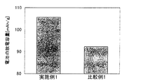
- Example 1 discharge capacity measurement
- Comparative Example 1 discharge capacity measurement Using the evaluation batteries obtained in Example 1 and Comparative Example 1, the discharge capacity was measured. The evaluation battery was charged and discharged at SOC 0% to SOC 100%, and the discharge capacity was measured. The result is shown in FIG. As shown in FIG. 5, the evaluation battery obtained in Example 1 was confirmed to have a higher discharge capacity than Comparative Example 1. This is considered to be because Li ion conduction was inhibited from being inhibited by using a sulfide solid electrolyte material substantially free of cross-linked sulfur and a linear polymer.
Landscapes
- Chemical & Material Sciences (AREA)
- Engineering & Computer Science (AREA)
- General Chemical & Material Sciences (AREA)
- Chemical Kinetics & Catalysis (AREA)
- Electrochemistry (AREA)
- Manufacturing & Machinery (AREA)
- Materials Engineering (AREA)
- Inorganic Chemistry (AREA)
- Physics & Mathematics (AREA)
- Condensed Matter Physics & Semiconductors (AREA)
- General Physics & Mathematics (AREA)
- Secondary Cells (AREA)
- Battery Electrode And Active Subsutance (AREA)
Abstract
The present invention addresses the problem of providing an electrode layer for a secondary cell that minimizes increased cell resistance and diminished discharge capacity. The present invention solves the problem by providing an electrode layer for a secondary cell, characterized by containing an active material, a sulfide solid electrolyte material substantially devoid of crosslinked sulfur, and a straight-chain polymer for binding the active material and the sulfide solid electrolyte material.
Description
本発明は、電池抵抗の増加および放電容量の低下を抑制した二次電池用電極層に関する。
The present invention relates to an electrode layer for a secondary battery in which an increase in battery resistance and a decrease in discharge capacity are suppressed.
さまざまな電池の中でも、軽量で高出力・高エネルギー密度という利点を持つリチウム電池は、小型携帯電子機器や携帯情報端末等の電源として多用され、現在の情報化社会を支えている。また、電気自動車やハイブリッド車の電源としても、リチウム電池が注目されており、更なる高エネルギー密度化、安全性の向上および大型化が求められている。
Among various batteries, lithium batteries, which have the advantages of light weight, high output, and high energy density, are widely used as power sources for small portable electronic devices and portable information terminals, and support the current information society. Further, lithium batteries are attracting attention as power sources for electric vehicles and hybrid vehicles, and further higher energy density, improved safety, and larger size are required.
現在市販されているリチウム電池は、可燃性の有機溶媒を含む電解液が使用されているため、短絡時の温度上昇を抑える安全装置の取り付けや短絡防止のための構造・材料面での改善が必要となる。これに対し、電解液を固体電解質層に変えて、電池を全固体化したリチウム電池は、電池内に可燃性の有機溶媒を用いないので、安全装置の簡素化が図れ、製造コストや生産性に優れると考えられている。
Since lithium batteries currently on the market use an electrolyte containing a flammable organic solvent, it is possible to install safety devices that suppress the temperature rise during short circuits and to improve the structure and materials to prevent short circuits. Necessary. In contrast, a lithium battery in which the electrolyte is changed to a solid electrolyte layer to make the battery completely solid does not use a flammable organic solvent in the battery, so the safety device can be simplified, and manufacturing costs and productivity can be reduced. It is considered excellent.
このような全固体リチウム電池の分野において、硫化物固体電解質材料を、固体電解質層や電極層に用いることにより、全固体リチウム電池のLiイオン伝導性を向上させることが知られている。
In the field of such all solid lithium batteries, it is known to improve the Li ion conductivity of all solid lithium batteries by using a sulfide solid electrolyte material for a solid electrolyte layer or an electrode layer.
一方、固体電解質層や電極層に、結着材としてポリマーを添加する試みがある。ポリマーを添加することにより、層に可撓性を付与することができ、加工性や成形性を向上させることができる。例えば、特許文献1においては、水素添加ブタジエンゴム(HBR)を結着材として用い、硫化物固体電解質材料として0.5Li2S-0.5P2S5を用いた固体電解質層および電極層が開示されている。また、特許文献2においては、水素添加ブロック共重合体を含有する水素吸蔵合金電極用結着剤が開示されている。
On the other hand, there is an attempt to add a polymer as a binder to the solid electrolyte layer or the electrode layer. By adding a polymer, flexibility can be imparted to the layer, and processability and moldability can be improved. For example, in Patent Document 1, a solid electrolyte layer and an electrode layer using hydrogenated butadiene rubber (HBR) as a binder and 0.5Li 2 S-0.5P 2 S 5 as a sulfide solid electrolyte material are provided. It is disclosed. Moreover, in patent document 2, the binder for hydrogen storage alloy electrodes containing a hydrogenated block copolymer is disclosed.
特許文献1において使用される0.5Li2S-0.5P2S5は、架橋硫黄を有する硫化物固体電解質材料であるため、反応性が高く、結着材と反応することにより劣化し、Liイオン伝導度が低下してしまう。また、結着材が硫化物固体電解質材料や活物質の粒子表面を被覆することにより、Liイオン伝導度が低下するおそれがある。このため、電池抵抗が増加し、放電容量が低下するという問題がある。
Since 0.5Li 2 S-0.5P 2 S 5 used in Patent Document 1 is a sulfide solid electrolyte material having bridging sulfur, it is highly reactive and deteriorates by reacting with the binder, Li ion conductivity will fall. Moreover, there is a possibility that the Li ion conductivity may be lowered by covering the particle surface of the sulfide solid electrolyte material or the active material with the binder. For this reason, there exists a problem that battery resistance increases and discharge capacity falls.
本発明は、上記問題点に鑑みてなされたものであり、電池抵抗の増加および放電容量の低下を抑制した二次電池用電極層を提供することを主目的とする。
The present invention has been made in view of the above problems, and has as its main object to provide an electrode layer for a secondary battery that suppresses an increase in battery resistance and a decrease in discharge capacity.
上記課題を解決するために、本発明においては、活物質と、実質的に架橋硫黄を有しない硫化物固体電解質材料と、上記活物質および上記硫化物固体電解質材料を結着する直鎖状ポリマーとを含有することを特徴とする二次電池用電極層を提供する。
In order to solve the above problems, in the present invention, an active material, a sulfide solid electrolyte material substantially free of cross-linked sulfur, and a linear polymer that binds the active material and the sulfide solid electrolyte material. An electrode layer for a secondary battery is provided.
本発明によれば、実質的に架橋硫黄を有しない硫化物固体電解質材料と、直鎖状ポリマーとを用いることで、イオン伝導(例えば、Liイオン伝導)が阻害されることをを抑制でき、電池抵抗の増加および放電容量の低下を抑制した二次電池用電極層とすることができる。
According to the present invention, it is possible to suppress inhibition of ionic conduction (for example, Li ionic conduction) by using a sulfide solid electrolyte material substantially free of cross-linked sulfur and a linear polymer, It can be set as the electrode layer for secondary batteries which suppressed increase in battery resistance and decline in discharge capacity.
上記発明においては、上記直鎖状ポリマーが、水素添加ポリマーであることが好ましい。二次電池用電極層の抵抗増加および容量低下をさらに抑制することができるからである。
In the above invention, the linear polymer is preferably a hydrogenated polymer. This is because an increase in resistance and a decrease in capacity of the secondary battery electrode layer can be further suppressed.
上記発明においては、上記硫化物固体電解質材料が、Li2S-P2S5材料であることが好ましい。Liイオン伝導性に優れた硫化物固体電解質材料とすることができるからである。
In the above invention, the sulfide solid electrolyte material is preferably a Li 2 S—P 2 S 5 material. It is because it can be set as the sulfide solid electrolyte material excellent in Li ion conductivity.
上記発明においては、上記Li2S-P2S5材料におけるLi2SおよびP2S5の割合が、モル換算で、Li2S:P2S5=72:28~78:22の範囲内であることが好ましい。より架橋硫黄の少ない硫化物固体電解質材料とすることができるからである。
In the above invention, the ratio of Li 2 S and P 2 S 5 in the Li 2 S—P 2 S 5 material is in the range of Li 2 S: P 2 S 5 = 72: 28 to 78:22 in terms of mole. It is preferable to be within. This is because a sulfide solid electrolyte material with less crosslinking sulfur can be obtained.
また、本発明においては、実質的に架橋硫黄を有しない硫化物固体電解質材料と、上記硫化物固体電解質材料を結着する直鎖状ポリマーとを含有することを特徴とする固体電解質層を提供する。
The present invention also provides a solid electrolyte layer comprising a sulfide solid electrolyte material substantially free of cross-linked sulfur and a linear polymer binding the sulfide solid electrolyte material. To do.
本発明によれば、実質的に架橋硫黄を有しない硫化物固体電解質材料と、直鎖状ポリマーとを用いることで、イオン伝導(例えば、Liイオン伝導)が阻害されることをを抑制でき、電池抵抗の増加を抑制した固体電解質層とすることができる。
According to the present invention, it is possible to suppress inhibition of ionic conduction (for example, Li ionic conduction) by using a sulfide solid electrolyte material substantially free of cross-linked sulfur and a linear polymer, It can be set as the solid electrolyte layer which suppressed the increase in battery resistance.
上記発明においては、上記直鎖状ポリマーが、水素添加ポリマーであることが好ましい。固体電解質層の抵抗増加をさらに抑制することができるからである。
In the above invention, the linear polymer is preferably a hydrogenated polymer. This is because an increase in resistance of the solid electrolyte layer can be further suppressed.
上記発明においては、上記硫化物固体電解質材料が、Li2S-P2S5材料であることが好ましい。Liイオン伝導性に優れた硫化物固体電解質材料とすることができるからである。
In the above invention, the sulfide solid electrolyte material is preferably a Li 2 S—P 2 S 5 material. It is because it can be set as the sulfide solid electrolyte material excellent in Li ion conductivity.
上記発明においては、上記Li2S-P2S5材料におけるLi2SおよびP2S5の割合が、モル換算で、Li2S:P2S5=72:28~78:22の範囲内であることが好ましい。より架橋硫黄の少ない硫化物固体電解質材料とすることができるからである。
In the above invention, the ratio of Li 2 S and P 2 S 5 in the Li 2 S—P 2 S 5 material is in the range of Li 2 S: P 2 S 5 = 72: 28 to 78:22 in terms of mole. It is preferable to be within. This is because a sulfide solid electrolyte material with less crosslinking sulfur can be obtained.
また、本発明においては、正極活物質を含有する正極層と、負極活物質を含有する負極層と、上記正極層および上記負極層の間に形成された固体電解質層とを有する全固体二次電池であって、上記正極層および上記負極層の少なくとも一方が、上述した二次電池用電極層であることを特徴とする全固体二次電池を提供する。
Further, in the present invention, an all-solid secondary having a positive electrode layer containing a positive electrode active material, a negative electrode layer containing a negative electrode active material, and a solid electrolyte layer formed between the positive electrode layer and the negative electrode layer. An all-solid secondary battery is provided, wherein at least one of the positive electrode layer and the negative electrode layer is the above-described electrode layer for a secondary battery.
本発明によれば、上述した二次電池用電極層を用いることにより、電池抵抗が低く、放電容量の大きい全固体二次電池とすることができる。また、活物質と硫化物固体電解質材料との反応による高抵抗層の生成を抑制することができ、電池抵抗の低い全固体二次電池とすることができる。
According to the present invention, by using the above-described electrode layer for a secondary battery, an all-solid secondary battery having a low battery resistance and a large discharge capacity can be obtained. Moreover, the production | generation of the high resistance layer by reaction with an active material and sulfide solid electrolyte material can be suppressed, and it can be set as an all-solid-state secondary battery with low battery resistance.
また、本発明においては、正極活物質を含有する正極層と、負極活物質を含有する負極層と、上記正極層および上記負極層の間に形成された固体電解質層とを有する全固体二次電池であって、上記固体電解質層が、上述した固体電解質層であることを特徴とする全固体二次電池を提供する。
Further, in the present invention, an all-solid secondary having a positive electrode layer containing a positive electrode active material, a negative electrode layer containing a negative electrode active material, and a solid electrolyte layer formed between the positive electrode layer and the negative electrode layer. An all-solid secondary battery is provided, wherein the solid electrolyte layer is the solid electrolyte layer described above.
本発明によれば、上述した固体電解質層を用いることにより、電池抵抗の低い全固体二次電池とすることができる。
According to the present invention, an all-solid secondary battery with low battery resistance can be obtained by using the solid electrolyte layer described above.
本発明においては、電池抵抗の増加および放電容量の低下を抑制した二次電池用電極層を得ることができるという効果を奏する。
In the present invention, there is an effect that an electrode layer for a secondary battery in which an increase in battery resistance and a decrease in discharge capacity are suppressed can be obtained.
以下、本発明の二次電池用電極層、固体電解質層および全固体二次電池について、詳細に説明する。
Hereinafter, the electrode layer for a secondary battery, the solid electrolyte layer, and the all-solid secondary battery of the present invention will be described in detail.
A.二次電池用電極層
まず、本発明の二次電池用電極層について説明する。本発明の二次電池用電極層は、活物質と、実質的に架橋硫黄を有しない硫化物固体電解質材料と、上記活物質および上記硫化物固体電解質材料を結着する直鎖状ポリマーとを含有することを特徴とするものである。 A. Secondary Battery Electrode Layer First, the secondary battery electrode layer of the present invention will be described. An electrode layer for a secondary battery of the present invention comprises an active material, a sulfide solid electrolyte material substantially free of cross-linked sulfur, and a linear polymer that binds the active material and the sulfide solid electrolyte material. It is characterized by containing.
まず、本発明の二次電池用電極層について説明する。本発明の二次電池用電極層は、活物質と、実質的に架橋硫黄を有しない硫化物固体電解質材料と、上記活物質および上記硫化物固体電解質材料を結着する直鎖状ポリマーとを含有することを特徴とするものである。 A. Secondary Battery Electrode Layer First, the secondary battery electrode layer of the present invention will be described. An electrode layer for a secondary battery of the present invention comprises an active material, a sulfide solid electrolyte material substantially free of cross-linked sulfur, and a linear polymer that binds the active material and the sulfide solid electrolyte material. It is characterized by containing.
本発明によれば、実質的に架橋硫黄を有しない硫化物固体電解質材料と、直鎖状ポリマーとを用いることで、イオン伝導(例えば、Liイオン伝導)が阻害されることを抑制でき、電池抵抗の増加および放電容量の低下を抑制した二次電池用電極層とすることができる。従来、電極層に結着材を用いた場合、結着材が電極材料の粒子表面を被覆するため、物理的にイオン伝導が阻害されてしまうという問題がある。これに対して、本発明においては、結着材として直鎖状ポリマーを用いることで、直鎖状ポリマーは繊維状に活物質および硫化物固体電解質材料の粒子をつなぐため、結着材の粒子表面への接着面積が小さくなり、イオン伝導阻害を起こしにくくすることができ、結果として、二次電池用電極層の抵抗増加および放電容量の低下を抑制することができる。
According to the present invention, by using a sulfide solid electrolyte material substantially free of cross-linked sulfur and a linear polymer, it is possible to suppress inhibition of ionic conduction (for example, Li ionic conduction), and a battery. It can be set as the electrode layer for secondary batteries which suppressed the increase in resistance and the fall of discharge capacity. Conventionally, when a binder is used for the electrode layer, the binder covers the particle surface of the electrode material, so that there is a problem that ion conduction is physically hindered. In contrast, in the present invention, by using a linear polymer as the binder, the linear polymer connects the particles of the active material and the sulfide solid electrolyte material in a fibrous form. The adhesion area to the surface is reduced, and it is possible to make it difficult for ion conduction inhibition to occur. As a result, it is possible to suppress an increase in resistance and a decrease in discharge capacity of the electrode layer for secondary batteries.
本発明においては、実質的に架橋硫黄を有しない硫化物固体電解質材料を用いる。架橋硫黄(例えば、S3P-S-PS3ユニットの架橋硫黄)は反応性が高いため、結着材と反応することで、硫化物固体電解質材料の劣化の原因となる。これに対し、本発明における硫化物固体電解質材料は、実質的に架橋硫黄を有しないため、劣化しにくく、二次電池用電極層の抵抗増加を抑制することができる。
In the present invention, a sulfide solid electrolyte material having substantially no bridging sulfur is used. Since bridging sulfur (for example, bridging sulfur of S 3 P—S—PS 3 units) is highly reactive, it reacts with the binder to cause deterioration of the sulfide solid electrolyte material. On the other hand, since the sulfide solid electrolyte material in this invention does not have bridge | crosslinking sulfur substantially, it is hard to deteriorate and it can suppress the resistance increase of the electrode layer for secondary batteries.
また、二次電池用電極層に含まれる活物質は、通常、架橋硫黄を有する硫化物固体電解質材料と反応し、高抵抗層を生成する。これに対して、本発明においては、実質的に架橋硫黄を有しない硫化物固体電解質材料を用いることにより、高抵抗層の生成を抑制できる。その結果、より抵抗の低い二次電池用電極層とすることができる。
In addition, the active material contained in the electrode layer for the secondary battery usually reacts with the sulfide solid electrolyte material having bridging sulfur to generate a high resistance layer. On the other hand, in this invention, the production | generation of a high resistance layer can be suppressed by using the sulfide solid electrolyte material which does not have bridge | crosslinking sulfur substantially. As a result, the electrode layer for a secondary battery having a lower resistance can be obtained.
図1は、本発明の二次電池用電極層の一例を示す概略断面図である。図1に示される二次電池用電極層10は、活物質1と、実質的に架橋硫黄を有しない硫化物固体電解質材料2と、活物質1および硫化物固体電解質材料2を結着する直鎖状ポリマー3とを含有するものである。
以下、本発明の二次電池用電極層について、構成ごとに説明する。 FIG. 1 is a schematic cross-sectional view showing an example of an electrode layer for a secondary battery of the present invention. Theelectrode layer 10 for a secondary battery shown in FIG. 1 includes an active material 1, a sulfide solid electrolyte material 2 substantially free of cross-linked sulfur, and a direct connection between the active material 1 and the sulfide solid electrolyte material 2. The chain polymer 3 is contained.
Hereinafter, the electrode layer for secondary batteries of this invention is demonstrated for every structure.
以下、本発明の二次電池用電極層について、構成ごとに説明する。 FIG. 1 is a schematic cross-sectional view showing an example of an electrode layer for a secondary battery of the present invention. The
Hereinafter, the electrode layer for secondary batteries of this invention is demonstrated for every structure.
1.硫化物固体電解質材料
まず、本発明における硫化物固体電解質材料について説明する。本発明における硫化物固体電解質材料は、実質的に架橋硫黄を有しないものである。ここで、「架橋硫黄」とは、硫化物固体電解質材料の合成時に生じる-S-結合の硫黄元素をいう。「実質的に架橋硫黄を有しない」とは、硫化物固体電解質材料に含まれる架橋硫黄の割合が、直鎖状ポリマーとの反応で硫化物固体電解質材料を劣化させない程度に少ないことをいう。この場合、架橋硫黄の割合は、例えば、10mol%以下であることが好ましく、5mol%以下であることがより好ましい。 1. First, the sulfide solid electrolyte material in the present invention will be described. The sulfide solid electrolyte material in the present invention has substantially no cross-linking sulfur. Here, “bridged sulfur” refers to an —S—bonded sulfur element generated during the synthesis of the sulfide solid electrolyte material. “Substantially no cross-linking sulfur” means that the ratio of cross-linking sulfur contained in the sulfide solid electrolyte material is so small that the reaction with the linear polymer does not deteriorate the sulfide solid electrolyte material. In this case, the ratio of cross-linking sulfur is, for example, preferably 10 mol% or less, and more preferably 5 mol% or less.
まず、本発明における硫化物固体電解質材料について説明する。本発明における硫化物固体電解質材料は、実質的に架橋硫黄を有しないものである。ここで、「架橋硫黄」とは、硫化物固体電解質材料の合成時に生じる-S-結合の硫黄元素をいう。「実質的に架橋硫黄を有しない」とは、硫化物固体電解質材料に含まれる架橋硫黄の割合が、直鎖状ポリマーとの反応で硫化物固体電解質材料を劣化させない程度に少ないことをいう。この場合、架橋硫黄の割合は、例えば、10mol%以下であることが好ましく、5mol%以下であることがより好ましい。 1. First, the sulfide solid electrolyte material in the present invention will be described. The sulfide solid electrolyte material in the present invention has substantially no cross-linking sulfur. Here, “bridged sulfur” refers to an —S—bonded sulfur element generated during the synthesis of the sulfide solid electrolyte material. “Substantially no cross-linking sulfur” means that the ratio of cross-linking sulfur contained in the sulfide solid electrolyte material is so small that the reaction with the linear polymer does not deteriorate the sulfide solid electrolyte material. In this case, the ratio of cross-linking sulfur is, for example, preferably 10 mol% or less, and more preferably 5 mol% or less.
また、「実質的に架橋硫黄を有しない」ことは、ラマン分光スペクトルにより、確認することもできる。例えば、本発明における硫化物固体電解質材料が、Li2S-P2S5材料である場合、架橋硫黄を有するS3P-S-PS3ユニット(P2S7ユニット)のピークが生じ得る。このピークは、通常402cm-1に現れる。そのため、本発明においては、このピークが検出されないことが好ましい。また、PS4ユニットのピークは、通常417cm-1に現れる。本発明においては、402cm-1における強度I402が、417cm-1における強度I417よりも小さいことが好ましい。より具体的には、強度I417に対して、強度I402は、例えば、70%以下であることが好ましく、50%以下であることがより好ましく、35%以下であることがさらに好ましい。また、Li2S-P2S5材料以外の硫化物固体電解質材料についても、架橋硫黄を有するユニットを特定し、そのユニットのピークを測定することにより、実質的に架橋硫黄を有しないことを判断することができる。なお、「実質的に架橋硫黄を有しない」ことは、ラマン分光スペクトルの測定結果以外にも、硫化物固体電解質材料を合成する際の原料組成比、NMRの測定結果を用いても確認することができる。
Further, “substantially no cross-linking sulfur” can be confirmed by a Raman spectroscopic spectrum. For example, when the sulfide solid electrolyte material in the present invention is a Li 2 S—P 2 S 5 material, a peak of S 3 P—S—PS 3 unit (P 2 S 7 unit) having bridging sulfur may occur. . This peak usually appears at 402 cm −1 . Therefore, in the present invention, it is preferable that this peak is not detected. The peak of PS 4 units usually appears at 417 cm −1 . In the present invention, the intensity I 402 at 402 cm -1 is preferably smaller than the intensity I 417 at 417 cm -1. More specifically, with respect to the intensity I 417 , the intensity I 402 is, for example, preferably 70% or less, more preferably 50% or less, and even more preferably 35% or less. Further, for sulfide solid electrolyte materials other than Li 2 S—P 2 S 5 material, it is confirmed that a unit having cross-linked sulfur is specified, and the peak of the unit is measured, so that it has substantially no cross-linked sulfur. Judgment can be made. Note that “substantially no cross-linked sulfur” can be confirmed by using the raw material composition ratio when synthesizing the sulfide solid electrolyte material and the NMR measurement result in addition to the measurement result of the Raman spectrum. Can do.
本発明における硫化物固体電解質材料は、実質的に架橋硫黄を有しないものであれば特に限定されるものではない。ここで、本発明の二次電池用電極層が全固体リチウム電池に用いられる場合、上記硫化物固体電解質材料として、例えば、Li2Sと、第13族~第15族の元素の硫化物とを含有する原料組成物を用いてなるものを挙げることができる。上記第13族~第15族の元素としては、例えば、B、Al、Si、Ge、P、As、Sb等を挙げることができ、上記第13族~第15族の元素の硫化物としては、具体的には、B2S3、Al2S3、SiS2、GeS2、P2S3、P2S5、As2S3、Sb2S3等を挙げることができる。中でも、本発明においては、Li2Sと、第13族~第15族の元素の硫化物とを含有する原料組成物を用いてなる硫化物固体電解質材料が、Li2S-P2S5材料、Li2S-SiS2材料、Li2S-GeS2材料、Li2S-Al2S3材料またはLi2S-B2S3材料であることが好ましく、Li2S-P2S5材料であることがより好ましい。Liイオン伝導性に優れているからである。なお、Li2S-P2S5材料とは、Li2SおよびP2S5を含有する原料組成物を用いてなる硫化物固体電解質材料であり、Li2SおよびP2S5を主原料として含むものであれば良く、さらに他の材料を含むものであっても良い。他の記載も同様である。
The sulfide solid electrolyte material in the present invention is not particularly limited as long as it does not substantially contain crosslinking sulfur. Here, when the electrode layer for a secondary battery of the present invention is used for an all-solid lithium battery, examples of the sulfide solid electrolyte material include Li 2 S and sulfides of elements of Group 13 to Group 15; What uses the raw material composition containing this can be mentioned. Examples of the Group 13 to Group 15 elements include B, Al, Si, Ge, P, As, and Sb. Examples of the Group 13 to Group 15 element sulfides include: Specific examples include B 2 S 3 , Al 2 S 3 , SiS 2 , GeS 2 , P 2 S 3 , P 2 S 5 , As 2 S 3 , Sb 2 S 3 and the like. In particular, in the present invention, a sulfide solid electrolyte material using a raw material composition containing Li 2 S and a sulfide of an element belonging to Group 13 to Group 15 is Li 2 S—P 2 S 5. Preferably, the material is Li 2 S—SiS 2 material, Li 2 S—GeS 2 material, Li 2 S—Al 2 S 3 material or Li 2 S—B 2 S 3 material, and Li 2 S—P 2 S 5 materials are more preferable. This is because the Li ion conductivity is excellent. Incidentally, Li and the 2 S-P 2 S 5 material, a sulfide solid electrolyte material obtained by using a raw material composition containing Li 2 S and P 2 S 5, Li 2 S and P 2 S 5 the main What is necessary is just to contain as a raw material, and also other materials may be included. The other description is the same.
上記原料組成物に含まれるLi2Sは、不純物が少ないことが好ましい。副反応を抑制することができるからである。Li2Sの合成方法としては、例えば、特開平7-330312号公報に記載された方法等を挙げることができる。さらに、Li2Sは、WO2005/040039に記載された方法等を用いて精製されていることが好ましい。また、原料組成物は、Li2S、および第13族~第15族の元素の硫化物の他に、Li3PO4、Li4SiO4、Li4GeO4、Li3BO3およびLi3AlO3からなる群から選択される少なくとも一種のオルトオキソ酸リチウムを含有していても良い。このようなオルトオキソ酸リチウムを加えることで、より安定な硫化物固体電解質材料を得ることができる。
Li 2 S contained in the raw material composition preferably has few impurities. This is because side reactions can be suppressed. Examples of the method for synthesizing Li 2 S include the method described in JP-A-7-330312. Furthermore, Li 2 S is preferably purified using the method described in WO2005 / 040039. In addition to Li 2 S and Group 13 to Group 15 element sulfides, the raw material composition includes Li 3 PO 4 , Li 4 SiO 4 , Li 4 GeO 4 , Li 3 BO 3, and Li 3. It may contain at least one lithium orthooxoate selected from the group consisting of AlO 3 . By adding such a lithium orthooxo acid, a more stable sulfide solid electrolyte material can be obtained.
また、本発明における硫化物固体電解質材料が、Li2Sを含有する原料組成物を用いてなるものである場合、上記硫化物固体電解質材料は、実質的にLi2Sを有しないことが好ましい。「実質的にLi2Sを有しない」とは、出発原料に由来するLi2Sを実質的に含有しないことをいう。Li2Sは、架橋硫黄と同様に反応性が高いため、含まれないことが好ましい。「実質的にLi2Sを有しない」ことは、X線回折により確認することができる。具体的には、Li2Sのピーク(2θ=27.0°、31.2°、44.8°、53.1°)を有しない場合は、Li2Sを実質的に含有しないと判断することができる。なお、原料組成物におけるLi2Sの割合が大きすぎると、硫化物固体電解質材料がLi2Sを含む傾向にあり、逆に、原料組成物におけるLi2Sの割合が小さすぎると、硫化物固体電解質材料が上述した架橋硫黄を含む傾向にある。
In addition, when the sulfide solid electrolyte material in the present invention is formed using a raw material composition containing Li 2 S, the sulfide solid electrolyte material preferably has substantially no Li 2 S. . By "substantially free of Li 2 S" it means that it does not contain Li 2 S derived from starting materials substantially. Li 2 S is preferably not included because it has a high reactivity like bridging sulfur. “Substantially no Li 2 S” can be confirmed by X-ray diffraction. Specifically, when it does not have a Li 2 S peak (2θ = 27.0 °, 31.2 °, 44.8 °, 53.1 °), it is determined that it does not substantially contain Li 2 S. can do. If the ratio of Li 2 S in the raw material composition is too large, the sulfide solid electrolyte material tends to contain Li 2 S. Conversely, if the ratio of Li 2 S in the raw material composition is too small, the sulfide The solid electrolyte material tends to contain the above-mentioned crosslinked sulfur.
本発明における硫化物固体電解質材料が、実質的に架橋硫黄およびLi2Sを有しない場合、通常、硫化物固体電解質材料は、オルト組成またはその近傍の組成を有している。ここで、オルトとは、一般的に、同じ酸化物を水和して得られるオキソ酸の中で、最も水和度の高いものをいう。本発明においては、硫化物で最もLi2Sが付加している結晶組成をオルト組成という。例えば、Li2S-P2S5系ではLi3PS4がオルト組成に該当し、Li2S-SiS2系ではLi4SiS4がオルト組成に該当し、Li2S-GeS2系ではLi4GeS4がオルト組成に該当し、Li2S-Al2S3系ではLi3AlS3がオルト組成に該当し、Li2S-B2S3系ではLi3BS3がオルト組成に該当する。
When the sulfide solid electrolyte material in the present invention does not substantially contain bridging sulfur and Li 2 S, the sulfide solid electrolyte material usually has an ortho composition or a composition in the vicinity thereof. Here, ortho generally refers to one having the highest degree of hydration among oxo acids obtained by hydrating the same oxide. In the present invention, the crystal composition in which Li 2 S is added most in the sulfide is called the ortho composition. For example, in the Li 2 S—P 2 S 5 system, Li 3 PS 4 corresponds to the ortho composition, in the Li 2 S—SiS 2 system, Li 4 SiS 4 corresponds to the ortho composition, and in the Li 2 S—GeS 2 system. Li 4 GeS 4 corresponds to the ortho composition, Li 2 S—Al 2 S 3 system corresponds to the Li 3 AlS 3 ortho composition, and Li 2 S—B 2 S 3 system corresponds to the Li 3 BS 3 ortho composition. Applicable.
また、Li2S-P2S5系の硫化物固体電解質材料の場合、オルト組成を得るLi2SおよびP2S5の割合は、モル基準で、Li2S:P2S5=75:25である。Li2S-Al2S3系の硫化物固体電解質材料の場合、Li2S-B2S3系の硫化物固体電解質材料の場合も同様である。一方、Li2S-SiS2系の硫化物固体電解質材料の場合、オルト組成を得るLi2SおよびSiS2の割合は、モル基準で、Li2S:SiS2=66.7:33.3である。Li2S-GeS2系の硫化物固体電解質材料の場合も同様である。
In the case of a Li 2 S—P 2 S 5 sulfide solid electrolyte material, the ratio of Li 2 S and P 2 S 5 to obtain the ortho composition is Li 2 S: P 2 S 5 = 75 on a molar basis. : 25. The same applies to a Li 2 S—Al 2 S 3 -based sulfide solid electrolyte material and a Li 2 S—B 2 S 3 -based sulfide solid electrolyte material. On the other hand, in the case of a Li 2 S—SiS 2 -based sulfide solid electrolyte material, the ratio of Li 2 S and SiS 2 to obtain the ortho composition is Li 2 S: SiS 2 = 66.7: 33.3 on a molar basis. It is. The same applies to the case of a Li 2 S—GeS 2 -based sulfide solid electrolyte material.
本発明における硫化物固体電解質材料が、Li2S-P2S5材料である場合、Li2SおよびP2S5の割合は、モル換算で、Li2S:P2S5=72:28~78:22の範囲内であることが好ましく、Li2S:P2S5=73:27~77:23の範囲内であることがより好ましく、Li2S:P2S5=74:26~76:24の範囲内であることがさらに好ましい。両者の割合を、オルト組成を得る割合(Li2S:P2S5=75:25)およびその近傍を含む範囲とすることで、直鎖状ポリマーとの反応性をさらに低くすることができるからである。なお、上記硫化物固体電解質材料が、Li2S-Al2S3材料である場合、Li2S-B2S3材料である場合も同様である。一方、上記硫化物固体電解質材料が、Li2S-SiS2材料である場合、Li2SおよびSiS2の割合は、モル基準で、Li2S:SiS2=63:37~70:30の範囲内であることが好ましく、Li2S:SiS2=64:36~69:31の範囲内であることがより好ましく、Li2S:SiS2=65:35~68:32の範囲内であることがさらに好ましい。両者の割合を、オルト組成を得る割合(Li2S:SiS2=66.7:33.3)およびその近傍を含む範囲とすることで、直鎖状ポリマーとの反応性をさらに低くすることができるからである。なお、上記硫化物固体電解質材料が、Li2S-GeS2材料である場合も同様である。
When the sulfide solid electrolyte material in the present invention is a Li 2 S—P 2 S 5 material, the ratio of Li 2 S and P 2 S 5 is Li 2 S: P 2 S 5 = 72: It is preferably within the range of 28 to 78:22, more preferably within the range of Li 2 S: P 2 S 5 = 73: 27 to 77:23, and Li 2 S: P 2 S 5 = 74. : More preferably in the range of 26 to 76:24. By setting the ratio of both to a range including the ratio of obtaining the ortho composition (Li 2 S: P 2 S 5 = 75: 25) and the vicinity thereof, the reactivity with the linear polymer can be further reduced. Because. The same applies when the sulfide solid electrolyte material is a Li 2 S—Al 2 S 3 material or a Li 2 S—B 2 S 3 material. On the other hand, when the sulfide solid electrolyte material is a Li 2 S—SiS 2 material, the ratio of Li 2 S and SiS 2 is Li 2 S: SiS 2 = 63: 37 to 70:30 on a molar basis. It is preferably within the range, more preferably within the range of Li 2 S: SiS 2 = 64: 36 to 69:31, and within the range of Li 2 S: SiS 2 = 65: 35 to 68:32. More preferably it is. Reducing the reactivity with the linear polymer further by setting the ratio of both to a ratio that includes the ortho composition (Li 2 S: SiS 2 = 66.7: 33.3) and its vicinity. Because you can. The same applies when the sulfide solid electrolyte material is a Li 2 S—GeS 2 material.
本発明における硫化物固体電解質材料は、硫化物ガラスであっても良く、その硫化物ガラスを熱処理して得られる結晶化硫化物ガラスであっても良い。硫化物ガラスは、例えば、上記原料組成物に対して、非晶質化法を行うことにより得ることができる。非晶質化法としては、例えば、メカニカルミリング法および溶融急冷法を挙げることができ、中でも、メカニカルミリング法が好ましい。常温での処理が可能になり、製造工程の簡略化を図ることができるからである。メカニカルミリングは、原料組成物を、機械的エネルギーを付与しながら混合する方法であれば特に限定されるものではないが、例えば、ボールミル、ターボミル、メカノフュージョン、ディスクミル等を挙げることができ、中でも、ボールミルが好ましく、特に、遊星型ボールミルが好ましい。所望の硫化物固体電解質材料を効率良く得ることができるからである。また、メカニカルミリングの条件は、所望の硫化物固体電解質材料を得ることができるように設定することが好ましい。一方、結晶化硫化物ガラスは、例えば、硫化物ガラスを結晶化温度以上の温度で熱処理することにより得ることができる。すなわち、原料組成物に対して、非晶質化法を行い、さらに熱処理を行うことにより、結晶化硫化物ガラスを得ることができる。なお、熱処理の条件によっては、架橋硫黄およびLi2Sが生成する可能性や安定相が生成する可能性があるため、本発明においては、これらが生成しないように、熱処理温度および熱処理時間を調整することが好ましい。
The sulfide solid electrolyte material in the present invention may be sulfide glass, or may be crystallized sulfide glass obtained by heat-treating the sulfide glass. The sulfide glass can be obtained, for example, by subjecting the raw material composition to an amorphization method. Examples of the amorphization method include a mechanical milling method and a melt quenching method, and among them, the mechanical milling method is preferable. This is because processing at room temperature is possible, and the manufacturing process can be simplified. Mechanical milling is not particularly limited as long as the raw material composition is mixed while imparting mechanical energy, and examples thereof include a ball mill, a turbo mill, a mechano-fusion, and a disk mill. A ball mill is preferable, and a planetary ball mill is particularly preferable. This is because a desired sulfide solid electrolyte material can be obtained efficiently. Moreover, it is preferable to set the conditions of mechanical milling so that a desired sulfide solid electrolyte material can be obtained. On the other hand, crystallized sulfide glass can be obtained, for example, by heat-treating sulfide glass at a temperature equal to or higher than the crystallization temperature. That is, a crystallized sulfide glass can be obtained by subjecting the raw material composition to an amorphization method and further a heat treatment. Depending on the heat treatment conditions, bridging sulfur and Li 2 S may be generated or a stable phase may be generated. Therefore, in the present invention, the heat treatment temperature and the heat treatment time are adjusted so that they are not formed. It is preferable to do.
本発明における硫化物固体電解質材料の形状としては、例えば、粒子形状を挙げることができ、中でも、真球状または楕円球状であることが好ましい。また、硫化物固体電解質材料が粒子形状である場合、その平均粒径(D50)は、例えば、0.1μm~50μmの範囲内であることが好ましい。なお、上記平均粒径は、例えば、粒度分布計により決定できる。また、本発明における硫化物固体電解質材料がLiイオン伝導体である場合、常温におけるLiイオン伝導度は、例えば、1×10⁻⁵S/cm以上であることが好ましく、1×10-4S/cm以上であることがより好ましい。
Examples of the shape of the sulfide solid electrolyte material in the present invention include a particle shape, and among them, a true spherical shape or an elliptical spherical shape is preferable. Further, when the sulfide solid electrolyte material has a particle shape, the average particle diameter (D 50 ) is preferably in the range of 0.1 μm to 50 μm, for example. In addition, the said average particle diameter can be determined with a particle size distribution meter, for example. Further, when the sulfide solid electrolyte material in the present invention is a Li ion conductor, the Li ion conductivity at room temperature is preferably 1 × 10 −5 S / cm or more, for example, 1 × 10 −4 S. / Cm or more is more preferable.
二次電池用電極層における硫化物固体電解質材料の含有量は、例えば、1質量%~90質量%の範囲内であることが好ましく、10質量%~50質量%の範囲内であることがより好ましい。硫化物固体電解質材料の含有量が少なすぎると、二次電池用電極層のイオン伝導性が低くなる可能性があるからであり、硫化物固体電解質材料の含有量が多すぎると、容量の低下が生じる可能性があるからである。
The content of the sulfide solid electrolyte material in the electrode layer for the secondary battery is, for example, preferably in the range of 1% by mass to 90% by mass, and more preferably in the range of 10% by mass to 50% by mass. preferable. This is because if the content of the sulfide solid electrolyte material is too small, the ionic conductivity of the electrode layer for the secondary battery may be lowered. If the content of the sulfide solid electrolyte material is too large, the capacity decreases. This is because there is a possibility of occurrence.
2.直鎖状ポリマー
次に、本発明における直鎖状ポリマーについて説明する。本発明における直鎖状ポリマーは、上述した硫化物固体電解質材料、および、後述する活物質を結着するものである。ここで、「直鎖状ポリマー」とは、直鎖状の構造を有するポリマーをいい、「直鎖状」とは、ポリマーの主鎖を形成する炭素原子が枝分かれ構造を作らずに、一本の鎖状に結合している構造をいう。直鎖状ポリマーは、結着材として二次電池用電極層に添加した際に、活物質および硫化物固体電解質材料の粒子を繊維状につなぐと考えられる。粒子を繊維状につなぐことで、結着材の粒子表面への接着面積が小さくなるため、イオン伝導(例えば、Liイオン伝導)が阻害されにくくなる。そのため、所望の可撓性を有し、かつ電池抵抗の増加および放電容量の低下を抑制した二次電池用電極層を得ることができる。 2. Next, the linear polymer in the present invention will be described. The linear polymer in the present invention binds the above-described sulfide solid electrolyte material and the active material described later. Here, the “linear polymer” means a polymer having a linear structure, and the “linear” means that one carbon atom forming the main chain of the polymer does not form a branched structure. It is a structure that is bound in a chain. The linear polymer is considered to connect the particles of the active material and the sulfide solid electrolyte material into a fibrous shape when added to the electrode layer for a secondary battery as a binder. By connecting the particles in a fibrous form, the area of adhesion of the binder to the particle surface is reduced, so that ionic conduction (for example, Li ion conduction) is less likely to be inhibited. Therefore, it is possible to obtain a secondary battery electrode layer having desired flexibility and suppressing increase in battery resistance and decrease in discharge capacity.
次に、本発明における直鎖状ポリマーについて説明する。本発明における直鎖状ポリマーは、上述した硫化物固体電解質材料、および、後述する活物質を結着するものである。ここで、「直鎖状ポリマー」とは、直鎖状の構造を有するポリマーをいい、「直鎖状」とは、ポリマーの主鎖を形成する炭素原子が枝分かれ構造を作らずに、一本の鎖状に結合している構造をいう。直鎖状ポリマーは、結着材として二次電池用電極層に添加した際に、活物質および硫化物固体電解質材料の粒子を繊維状につなぐと考えられる。粒子を繊維状につなぐことで、結着材の粒子表面への接着面積が小さくなるため、イオン伝導(例えば、Liイオン伝導)が阻害されにくくなる。そのため、所望の可撓性を有し、かつ電池抵抗の増加および放電容量の低下を抑制した二次電池用電極層を得ることができる。 2. Next, the linear polymer in the present invention will be described. The linear polymer in the present invention binds the above-described sulfide solid electrolyte material and the active material described later. Here, the “linear polymer” means a polymer having a linear structure, and the “linear” means that one carbon atom forming the main chain of the polymer does not form a branched structure. It is a structure that is bound in a chain. The linear polymer is considered to connect the particles of the active material and the sulfide solid electrolyte material into a fibrous shape when added to the electrode layer for a secondary battery as a binder. By connecting the particles in a fibrous form, the area of adhesion of the binder to the particle surface is reduced, so that ionic conduction (for example, Li ion conduction) is less likely to be inhibited. Therefore, it is possible to obtain a secondary battery electrode layer having desired flexibility and suppressing increase in battery resistance and decrease in discharge capacity.
本発明における直鎖状ポリマーは、エラストマーであることが好ましい。結着性に優れているからである。また、上記エラストマーは、熱硬化性エラストマーであっても良く、熱可塑性エラストマーであっても良いが、熱硬化性エラストマーであることが好ましく、ゴムであることがより好ましい。また、ゴムは、加硫されたものであっても良く、加硫されていないものであっても良い。
The linear polymer in the present invention is preferably an elastomer. This is because it has excellent binding properties. The elastomer may be a thermosetting elastomer or a thermoplastic elastomer, but is preferably a thermosetting elastomer, more preferably a rubber. The rubber may be vulcanized or unvulcanized.
また、本発明における直鎖状ポリマーは、炭化水素系ポリマーであることが好ましい。炭化水素系ポリマーは、炭素および水素から構成されるものであっても良く、炭素に結合する水素の一部または全部がフッ素等のハロゲンで置換されているものであっても良い。
In addition, the linear polymer in the present invention is preferably a hydrocarbon polymer. The hydrocarbon-based polymer may be composed of carbon and hydrogen, or may be one in which part or all of the hydrogen bonded to carbon is substituted with halogen such as fluorine.
また、本発明においては、上記炭化水素系ポリマーが、主鎖に二重結合を有するジエン系ポリマーであっても良く、主鎖に二重結合を有しない非ジエン系ポリマーであっても良いが、中でも、後者であることが好ましい。非ジエン系ポリマーは、主鎖に二重結合を有しないため、反応性が低く、硫化物固体電解質材料の劣化を抑制し、電池抵抗の増加を抑制できるからである。非ジエン系ポリマーとしては、例えば、エチレンプロピレンゴム(EPM)等のオレフィン系ポリマー、ポリフッ化ビニリデン(PVdF)等のフッ素系ポリマー等を挙げることができる。
In the present invention, the hydrocarbon polymer may be a diene polymer having a double bond in the main chain, or a non-diene polymer having no double bond in the main chain. Of these, the latter is preferred. This is because the non-diene polymer does not have a double bond in the main chain, and thus has low reactivity, can suppress deterioration of the sulfide solid electrolyte material, and can suppress increase in battery resistance. Examples of the non-diene polymer include olefin polymers such as ethylene propylene rubber (EPM), fluorine polymers such as polyvinylidene fluoride (PVdF), and the like.
一方、ジエン系ポリマーとしては、例えば、スチレンブタジエンゴム(SBR)、ブタジエンゴム(BR)、イソプレンゴム(IR)、クロロプレンゴム(CR)等を挙げることができる。
On the other hand, examples of the diene polymer include styrene butadiene rubber (SBR), butadiene rubber (BR), isoprene rubber (IR), chloroprene rubber (CR), and the like.
また、本発明においては、直鎖状ポリマーが、水素添加ポリマーであることが好ましい。二次電池用電極層の抵抗増加および容量低下をさらに抑制することができるからである。水素添加によって直鎖状ポリマーの不飽和結合の数が減ることで、直鎖状ポリマーが弾性変形しやすくなり、充放電に伴う活物質の膨張収縮を吸収しやすくなる。これにより、二次電池用電極層から活物質および硫化物固体電解質材料等の電極材料が剥離することを抑制できる。また、水素添加により直鎖状ポリマーの不飽和結合が少なくなるため、直鎖状ポリマーと、硫化物固体電解質材料に含まれる非架橋硫黄、および、僅かながら存在し得る架橋硫黄との反応性が低くなり、硫化物固体電解質材料の劣化を抑制できる。その結果、抵抗増加および容量低下を抑制した二次電池用電極層とすることができる。
In the present invention, the linear polymer is preferably a hydrogenated polymer. This is because an increase in resistance and a decrease in capacity of the secondary battery electrode layer can be further suppressed. By reducing the number of unsaturated bonds of the linear polymer by hydrogenation, the linear polymer is easily elastically deformed, and the expansion and contraction of the active material accompanying charge / discharge is easily absorbed. Thereby, it can suppress that electrode materials, such as an active material and a sulfide solid electrolyte material, peel from the electrode layer for secondary batteries. In addition, since the unsaturated bond of the linear polymer is reduced by hydrogenation, the reactivity between the linear polymer and the non-crosslinked sulfur contained in the sulfide solid electrolyte material and a slight amount of crosslinked sulfur is present. And the deterioration of the sulfide solid electrolyte material can be suppressed. As a result, it can be set as the electrode layer for secondary batteries which suppressed resistance increase and capacity | capacitance fall.
水素添加ポリマーとしては、例えば、水素添加スチレンブタジエンゴム(HSBR)、水素添加ブタジエンゴム(HBR)、水素添加イソプレンゴム(HIR)等を挙げることができ、中でも、HSBRおよびHBRが好ましい。二次電池用電極層に高い可撓性を与えることができるからである。
Examples of the hydrogenated polymer include hydrogenated styrene butadiene rubber (HSBR), hydrogenated butadiene rubber (HBR), hydrogenated isoprene rubber (HIR), etc. Among them, HSBR and HBR are preferable. It is because high flexibility can be given to the electrode layer for secondary batteries.
水素添加ポリマーの水素添加率としては、例えば、90%以上であることが好ましく、95%以上であることがより好ましい。水素添加ポリマーの水素添加率が低すぎると、直鎖状ポリマー中の不飽和結合があまり除去されず、上述した水素添加による効果を十分に発揮することができない可能性があるからである。
The hydrogenation rate of the hydrogenated polymer is, for example, preferably 90% or more, and more preferably 95% or more. This is because if the hydrogenation rate of the hydrogenated polymer is too low, unsaturated bonds in the linear polymer are not removed so much that the above-described effects of hydrogenation may not be fully exhibited.
また、直鎖状ポリマーの数平均分子量としては、例えば、1,000~700,000の範囲内であることが好ましく、10,000~500,000の範囲内であることがより好ましく、150,000~300,000の範囲内であることがさらに好ましい。直鎖状ポリマーの分子量が小さすぎると、所望の可撓性が得られない可能性があるからであり、直鎖状ポリマーの分子量が大きすぎると、溶媒に対する溶解性が低くなり、所望の分散状態が得られない可能性があるからである。なお、直鎖状ポリマーの数平均分子量は、例えば、ゲル浸透クロマトグラフィー(GPC)によって測定することができる。
The number average molecular weight of the linear polymer is, for example, preferably in the range of 1,000 to 700,000, more preferably in the range of 10,000 to 500,000, More preferably, it is in the range of 000 to 300,000. This is because if the molecular weight of the linear polymer is too small, the desired flexibility may not be obtained. If the molecular weight of the linear polymer is too large, the solubility in the solvent will be low and the desired dispersion will be achieved. This is because the state may not be obtained. In addition, the number average molecular weight of a linear polymer can be measured by gel permeation chromatography (GPC), for example.
二次電池用電極層における直鎖状ポリマーの含有量は、直鎖状ポリマーの種類に応じて異なるものであるが、例えば、0.01質量%~30質量%の範囲内であることが好ましく、0.1質量%~10質量%の範囲内であることがより好ましい。直鎖状ポリマーの含有量が少なすぎると、所望の可撓性を得られない可能性があるからであり、直鎖状ポリマーの含有量が多すぎると、イオン伝導性や電子伝導性が低下する可能性があるからである。
The content of the linear polymer in the electrode layer for a secondary battery varies depending on the type of the linear polymer, but is preferably in the range of 0.01% by mass to 30% by mass, for example. More preferably, the content is in the range of 0.1% by mass to 10% by mass. This is because if the content of the linear polymer is too small, the desired flexibility may not be obtained. If the content of the linear polymer is too large, the ionic conductivity and the electronic conductivity are lowered. Because there is a possibility of doing.
3.活物質
次に、本発明における活物質について説明する。本発明における活物質は、正極活物質であっても良く、負極活物質であっても良いが、中でも、正極活物質であることが好ましく、特に、酸化物正極活物質であることが好ましい。酸化物正極活物質は、架橋硫黄を有する硫化物固体電解質材料と反応し、高抵抗層を生成しやすいからである。本発明においては、実質的に架橋硫黄を有しない硫化物固体電解質材料を用いることにより、高抵抗層の生成を抑制することができる。また、酸化物正極活物質を用いることにより、エネルギー密度の高い二次電池用電極層を得ることができる。例えば、全固体リチウム電池に用いられる酸化物正極活物質としては、一般式LixMyOz(Mは遷移金属元素であり、x=0.02~2.2、y=1~2、z=1.4~4)で表される酸化物正極活物質を挙げることができる。上記一般式において、Mは、Co、Mn、Ni、VおよびFeからなる群から選択される少なくとも一種であることが好ましく、Co、NiおよびMnからなる群から選択される少なくとも一種であることがより好ましい。このような酸化物正極活物質としては、具体的には、LiCoO2、LiMnO2、LiNiO2、LiVO2、LiNi1/3Co1/3Mn1/3O2等の岩塩層状型正極活物質、LiMn2O4、Li(Ni0.5Mn1.5)O4等のスピネル型正極活物質等を挙げることができる。また、上記一般式LixMyOz以外の酸化物正極活物質としては、LiFePO4、LiMnPO4、LiCoPO4等のオリビン型正極活物質、Li2FeSiO4、Li2MnSiO4等のSi含有正極活物質等を挙げることができる。 3. Active Material Next, the active material in the present invention will be described. The active material in the present invention may be a positive electrode active material or a negative electrode active material. Among them, a positive electrode active material is preferable, and an oxide positive electrode active material is particularly preferable. This is because the oxide positive electrode active material easily reacts with the sulfide solid electrolyte material having bridging sulfur to easily form a high resistance layer. In the present invention, the use of a sulfide solid electrolyte material that does not substantially contain bridging sulfur can suppress the generation of a high resistance layer. Moreover, the electrode layer for secondary batteries with a high energy density can be obtained by using an oxide positive electrode active material. For example, as an oxide positive electrode active material used in an all-solid lithium battery, a general formula Li x M y O z (M is a transition metal element, x = 0.02 to 2.2, y = 1 to 2, An oxide positive electrode active material represented by z = 1.4 to 4) can be given. In the above general formula, M is preferably at least one selected from the group consisting of Co, Mn, Ni, V and Fe, and preferably at least one selected from the group consisting of Co, Ni and Mn. More preferred. As such an oxide positive electrode active material, specifically, a rock salt layered positive electrode active material such as LiCoO 2 , LiMnO 2 , LiNiO 2 , LiVO 2 , LiNi 1/3 Co 1/3 Mn 1/3 O 2, etc. , LiMn 2 O 4 , Li (Ni 0.5 Mn 1.5 ) O 4 and other spinel type positive electrode active materials. As oxide positive electrode active materials other than the above-mentioned general formula Li x M y O z, LiFePO 4, LiMnPO 4, LiCoPO olivine-type positive electrode active material such 4, Si content, such as Li 2 FeSiO 4, Li 2 MnSiO 4 A positive electrode active material etc. can be mentioned.
次に、本発明における活物質について説明する。本発明における活物質は、正極活物質であっても良く、負極活物質であっても良いが、中でも、正極活物質であることが好ましく、特に、酸化物正極活物質であることが好ましい。酸化物正極活物質は、架橋硫黄を有する硫化物固体電解質材料と反応し、高抵抗層を生成しやすいからである。本発明においては、実質的に架橋硫黄を有しない硫化物固体電解質材料を用いることにより、高抵抗層の生成を抑制することができる。また、酸化物正極活物質を用いることにより、エネルギー密度の高い二次電池用電極層を得ることができる。例えば、全固体リチウム電池に用いられる酸化物正極活物質としては、一般式LixMyOz(Mは遷移金属元素であり、x=0.02~2.2、y=1~2、z=1.4~4)で表される酸化物正極活物質を挙げることができる。上記一般式において、Mは、Co、Mn、Ni、VおよびFeからなる群から選択される少なくとも一種であることが好ましく、Co、NiおよびMnからなる群から選択される少なくとも一種であることがより好ましい。このような酸化物正極活物質としては、具体的には、LiCoO2、LiMnO2、LiNiO2、LiVO2、LiNi1/3Co1/3Mn1/3O2等の岩塩層状型正極活物質、LiMn2O4、Li(Ni0.5Mn1.5)O4等のスピネル型正極活物質等を挙げることができる。また、上記一般式LixMyOz以外の酸化物正極活物質としては、LiFePO4、LiMnPO4、LiCoPO4等のオリビン型正極活物質、Li2FeSiO4、Li2MnSiO4等のSi含有正極活物質等を挙げることができる。 3. Active Material Next, the active material in the present invention will be described. The active material in the present invention may be a positive electrode active material or a negative electrode active material. Among them, a positive electrode active material is preferable, and an oxide positive electrode active material is particularly preferable. This is because the oxide positive electrode active material easily reacts with the sulfide solid electrolyte material having bridging sulfur to easily form a high resistance layer. In the present invention, the use of a sulfide solid electrolyte material that does not substantially contain bridging sulfur can suppress the generation of a high resistance layer. Moreover, the electrode layer for secondary batteries with a high energy density can be obtained by using an oxide positive electrode active material. For example, as an oxide positive electrode active material used in an all-solid lithium battery, a general formula Li x M y O z (M is a transition metal element, x = 0.02 to 2.2, y = 1 to 2, An oxide positive electrode active material represented by z = 1.4 to 4) can be given. In the above general formula, M is preferably at least one selected from the group consisting of Co, Mn, Ni, V and Fe, and preferably at least one selected from the group consisting of Co, Ni and Mn. More preferred. As such an oxide positive electrode active material, specifically, a rock salt layered positive electrode active material such as LiCoO 2 , LiMnO 2 , LiNiO 2 , LiVO 2 , LiNi 1/3 Co 1/3 Mn 1/3 O 2, etc. , LiMn 2 O 4 , Li (Ni 0.5 Mn 1.5 ) O 4 and other spinel type positive electrode active materials. As oxide positive electrode active materials other than the above-mentioned general formula Li x M y O z, LiFePO 4, LiMnPO 4, LiCoPO olivine-type positive electrode active material such 4, Si content, such as Li 2 FeSiO 4, Li 2 MnSiO 4 A positive electrode active material etc. can be mentioned.
一方、本発明における負極活物質としては、例えば、金属活物質およびカーボン活物質を挙げることができる。金属活物質としては、例えば、In、Al、SiおよびSn等を挙げることができる。一方、カーボン活物質としては、例えば、メソカーボンマイクロビーズ(MCMB)、高配向性グラファイト(HOPG)、ハードカーボン、ソフトカーボン等を挙げることができる。
On the other hand, examples of the negative electrode active material in the present invention include a metal active material and a carbon active material. Examples of the metal active material include In, Al, Si, and Sn. On the other hand, examples of the carbon active material include mesocarbon microbeads (MCMB), highly oriented graphite (HOPG), hard carbon, and soft carbon.
活物質の形状としては、例えば、粒子形状を挙げることができ、中でも、真球状または楕円球状であることが好ましい。また、活物質が粒子形状である場合、その平均粒径(D50)は、例えば、0.1μm~50μmの範囲内であることが好ましい。なお、上記平均粒径は、例えば、粒度分布計により決定できる。また、二次電池用電極層における活物質の含有量は、例えば、10質量%~99質量%の範囲内であることが好ましく、20質量%~90質量%の範囲内であることがより好ましい。
Examples of the shape of the active material include a particle shape. Among them, a true spherical shape or an elliptical spherical shape is preferable. When the active material has a particle shape, the average particle diameter (D 50 ) is preferably in the range of 0.1 μm to 50 μm, for example. In addition, the said average particle diameter can be determined with a particle size distribution meter, for example. In addition, the content of the active material in the electrode layer for a secondary battery is, for example, preferably in the range of 10% by mass to 99% by mass, and more preferably in the range of 20% by mass to 90% by mass. .
4.二次電池用電極層
本発明の二次電池用電極層は、上述した活物質、硫化物固体電解質材料および直鎖状ポリマーを少なくとも含有するものである。さらに、本発明の二次電池用電極層は、導電化材を含有していても良い。導電化材の添加により、二次電池用電極層の電子伝導性を向上させることができる。導電化材としては、例えば、アセチレンブラック、ケッチェンブラック、カーボンファイバー等を挙げることができる。また、本発明の二次電池用電極層は、所望の可撓性を有することが好ましい。加工性および成形性に優れるからである。二次電池用電極層の形状としては、例えば、シート状およびペレット状等を挙げることができる。二次電池用電極層の厚さは、目的とする全固体二次電池の種類および二次電池用電極層の用途等によって異なるものであるが、例えば、1μm~200μmの範囲内であることが好ましい。 4). Secondary Battery Electrode Layer The secondary battery electrode layer of the present invention contains at least the above-described active material, sulfide solid electrolyte material, and linear polymer. Furthermore, the electrode layer for secondary batteries of the present invention may contain a conductive material. By adding a conductive material, the electronic conductivity of the electrode layer for a secondary battery can be improved. Examples of the conductive material include acetylene black, ketjen black, and carbon fiber. Moreover, it is preferable that the electrode layer for secondary batteries of this invention has desired flexibility. It is because it is excellent in workability and moldability. Examples of the shape of the electrode layer for the secondary battery include a sheet shape and a pellet shape. The thickness of the secondary battery electrode layer varies depending on the type of the intended all-solid secondary battery and the use of the secondary battery electrode layer, and may be in the range of 1 μm to 200 μm, for example. preferable.
本発明の二次電池用電極層は、上述した活物質、硫化物固体電解質材料および直鎖状ポリマーを少なくとも含有するものである。さらに、本発明の二次電池用電極層は、導電化材を含有していても良い。導電化材の添加により、二次電池用電極層の電子伝導性を向上させることができる。導電化材としては、例えば、アセチレンブラック、ケッチェンブラック、カーボンファイバー等を挙げることができる。また、本発明の二次電池用電極層は、所望の可撓性を有することが好ましい。加工性および成形性に優れるからである。二次電池用電極層の形状としては、例えば、シート状およびペレット状等を挙げることができる。二次電池用電極層の厚さは、目的とする全固体二次電池の種類および二次電池用電極層の用途等によって異なるものであるが、例えば、1μm~200μmの範囲内であることが好ましい。 4). Secondary Battery Electrode Layer The secondary battery electrode layer of the present invention contains at least the above-described active material, sulfide solid electrolyte material, and linear polymer. Furthermore, the electrode layer for secondary batteries of the present invention may contain a conductive material. By adding a conductive material, the electronic conductivity of the electrode layer for a secondary battery can be improved. Examples of the conductive material include acetylene black, ketjen black, and carbon fiber. Moreover, it is preferable that the electrode layer for secondary batteries of this invention has desired flexibility. It is because it is excellent in workability and moldability. Examples of the shape of the electrode layer for the secondary battery include a sheet shape and a pellet shape. The thickness of the secondary battery electrode layer varies depending on the type of the intended all-solid secondary battery and the use of the secondary battery electrode layer, and may be in the range of 1 μm to 200 μm, for example. preferable.
本発明の二次電池用電極層の製造方法としては、上記の二次電池用電極層を得ることができる方法であれば特に限定されるものではないが、例えば、活物質、硫化物固体電解質材料および直鎖状ポリマーを溶媒中で混合してスラリーを作製し、ドクターブレード法、ダイコート法、グラビアコート法等の塗工法を用いて、このスラリーを基板上に塗工した後、溶媒を乾燥する方法等を挙げることができる。上記溶媒としては、活物質、硫化物固体電解質材料および直鎖状ポリマーを分散させることができれば特に限定されるものではないが、硫化物固体電解質材料が極性溶媒と反応してしまうため、非極性溶媒を用いることが好ましい。非極性溶媒としては、例えば、飽和炭化水素系溶媒、芳香族炭化水素系溶媒、フッ素系溶媒、塩素系溶媒等を挙げることができる。
The method for producing a secondary battery electrode layer of the present invention is not particularly limited as long as it is a method capable of obtaining the above-mentioned secondary battery electrode layer. For example, an active material, a sulfide solid electrolyte is used. The material and linear polymer are mixed in a solvent to prepare a slurry, and this slurry is applied onto a substrate using a coating method such as a doctor blade method, a die coating method, or a gravure coating method, and then the solvent is dried. And the like. The solvent is not particularly limited as long as the active material, the sulfide solid electrolyte material, and the linear polymer can be dispersed. However, since the sulfide solid electrolyte material reacts with a polar solvent, it is nonpolar. It is preferable to use a solvent. Examples of nonpolar solvents include saturated hydrocarbon solvents, aromatic hydrocarbon solvents, fluorine solvents, chlorine solvents, and the like.
B.固体電解質層
次に、本発明の固体電解質層について説明する。本発明の固体電解質層は、実質的に架橋硫黄を有しない硫化物固体電解質材料と、上記硫化物固体電解質材料を結着する直鎖状ポリマーとを含有することを特徴とするものである。 B. Next, the solid electrolyte layer of the present invention will be described. The solid electrolyte layer of the present invention is characterized by containing a sulfide solid electrolyte material substantially free of cross-linked sulfur and a linear polymer that binds the sulfide solid electrolyte material.
次に、本発明の固体電解質層について説明する。本発明の固体電解質層は、実質的に架橋硫黄を有しない硫化物固体電解質材料と、上記硫化物固体電解質材料を結着する直鎖状ポリマーとを含有することを特徴とするものである。 B. Next, the solid electrolyte layer of the present invention will be described. The solid electrolyte layer of the present invention is characterized by containing a sulfide solid electrolyte material substantially free of cross-linked sulfur and a linear polymer that binds the sulfide solid electrolyte material.
本発明によれば、実質的に架橋硫黄を有しない硫化物固体電解質材料と、直鎖状ポリマーとを用いることで、イオン伝導(例えば、Liイオン伝導)が阻害されることを抑制でき、電池抵抗の増加を抑制した固体電解質層とすることができる。直鎖状ポリマーは、繊維状に硫化物固体電解質材料の粒子をつなぐため、結着材として直鎖状ポリマーを用いることにより、硫化物固体電解質材料の粒子表面への結着材の接着面積が小さくなり、イオン伝導を阻害されにくくすることができる。また、実質的に架橋硫黄を有しない硫化物固体電解質材料を用いることにより、結着材との反応により硫化物固体電解質材料が劣化することを抑制することができる。
なお、本発明における硫化物固体電解質材料および直鎖状ポリマーの利点については、上記「A.二次電池用電極層」に記載した内容と同様である。 According to the present invention, by using a sulfide solid electrolyte material substantially free of cross-linked sulfur and a linear polymer, it is possible to suppress inhibition of ionic conduction (for example, Li ionic conduction), and a battery. It can be set as the solid electrolyte layer which suppressed the increase in resistance. Since the linear polymer connects the particles of the sulfide solid electrolyte material in a fibrous form, the bonding area of the binder to the particle surface of the sulfide solid electrolyte material is reduced by using the linear polymer as the binder. It becomes small and can make it difficult to inhibit ionic conduction. In addition, by using a sulfide solid electrolyte material that substantially does not have cross-linked sulfur, it is possible to suppress deterioration of the sulfide solid electrolyte material due to a reaction with the binder.
The advantages of the sulfide solid electrolyte material and the linear polymer in the present invention are the same as those described in “A. Secondary battery electrode layer”.
図2は、本発明の固体電解質層の一例を示す概略断面図である。図2に示される固体電解質層11は、実質的に架橋硫黄を有しない硫化物固体電解質材料2と、硫化物固体電解質材料2を結着する直鎖状ポリマー3とを含有するものである。
FIG. 2 is a schematic sectional view showing an example of the solid electrolyte layer of the present invention. The solid electrolyte layer 11 shown in FIG. 2 contains a sulfide solid electrolyte material 2 that does not substantially contain bridging sulfur and a linear polymer 3 that binds the sulfide solid electrolyte material 2.
本発明の固体電解質層は、硫化物固体電解質材料と、直鎖状ポリマーとを少なくとも含有するものである。なお、硫化物固体電解質材料および直鎖状ポリマーについては、上記「A.二次電池用電極層」に記載した内容と同様であるので、ここでの記載は省略する。
The solid electrolyte layer of the present invention contains at least a sulfide solid electrolyte material and a linear polymer. The sulfide solid electrolyte material and the linear polymer are the same as the contents described in the above-mentioned “A. Secondary battery electrode layer”, and therefore the description thereof is omitted here.
固体電解質層における硫化物固体電解質材料の含有量は、多いことが好ましい。具体的には、50質量%以上であることが好ましく、70質量%以上であることがより好ましく、90質量%以上であることがさらに好ましく、95質量%以上であることが特に好ましい。
The content of the sulfide solid electrolyte material in the solid electrolyte layer is preferably large. Specifically, it is preferably 50% by mass or more, more preferably 70% by mass or more, further preferably 90% by mass or more, and particularly preferably 95% by mass or more.
また、固体電解質層における直鎖状ポリマーの含有量は、直鎖状ポリマーの種類に応じて異なるものであるが、例えば、0.01質量%~30質量%の範囲内であることが好ましく、0.1質量%~10質量%の範囲内であることがより好ましい。直鎖状ポリマーの含有量が少なすぎると、所望の可撓性が得られない可能性があるからであり、直鎖状ポリマーの含有量が多すぎると、イオン伝導性が低下する可能性があるからである。
In addition, the content of the linear polymer in the solid electrolyte layer varies depending on the type of the linear polymer, but is preferably in the range of 0.01% by mass to 30% by mass, for example. More preferably, it is within the range of 0.1% by mass to 10% by mass. This is because if the content of the linear polymer is too small, the desired flexibility may not be obtained. If the content of the linear polymer is too large, the ionic conductivity may be lowered. Because there is.
本発明の固体電解質層は、所望の可撓性を有することが好ましい。加工性および成形性に優れるからである。固体電解質層の形状としては、例えば、シート状およびペレット状等を挙げることができる。固体電解質層の厚さは、特に限定されるものではないが、例えば、0.1μm~1000μmの範囲内であることが好ましく、0.1μm~300μmの範囲内であることがより好ましい。
The solid electrolyte layer of the present invention preferably has a desired flexibility. It is because it is excellent in workability and moldability. Examples of the shape of the solid electrolyte layer include a sheet shape and a pellet shape. The thickness of the solid electrolyte layer is not particularly limited. For example, the thickness is preferably in the range of 0.1 μm to 1000 μm, and more preferably in the range of 0.1 μm to 300 μm.
本発明の固体電解質層の製造方法としては、上記の固体電解質層を形成することができる方法であれば特に限定されるものではないが、例えば、硫化物固体電解質材料および直鎖状ポリマーを溶媒中で混合してスラリーを作製し、ドクターブレード法、ダイコート法、グラビアコート法等の塗工法を用いて、このスラリーを基板上に塗工した後、溶媒を乾燥する方法等を挙げることができる。上記溶媒としては、硫化物固体電解質材料および直鎖状ポリマーを分散させることができれば特に限定されるものではないが、硫化物固体電解質材料が極性溶媒と反応してしまうため、非極性溶媒を用いることが好ましい。非極性溶媒としては、例えば、飽和炭化水素系溶媒、芳香族炭化水素系溶媒、フッ素系溶媒、塩素系溶媒等を挙げることができる。
The method for producing the solid electrolyte layer of the present invention is not particularly limited as long as it is a method capable of forming the above-mentioned solid electrolyte layer. For example, a sulfide solid electrolyte material and a linear polymer are used as a solvent. A slurry is prepared by mixing in a slurry, and a method of drying the solvent after coating this slurry on a substrate using a coating method such as a doctor blade method, a die coating method, or a gravure coating method can be exemplified. . The solvent is not particularly limited as long as the sulfide solid electrolyte material and the linear polymer can be dispersed. However, since the sulfide solid electrolyte material reacts with the polar solvent, a nonpolar solvent is used. It is preferable. Examples of nonpolar solvents include saturated hydrocarbon solvents, aromatic hydrocarbon solvents, fluorine solvents, chlorine solvents, and the like.
C.全固体二次電池
次に、本発明の全固体二次電池について説明する。本発明の全固体二次電池は、正極活物質を含有する正極層と、負極活物質を含有する負極層と、上記正極層および上記負極層の間に形成された固体電解質層とを有するものである。さらに、本発明の全固体二次電池は、二つの実施態様に大別することができる。以下、実施態様ごとに説明する。 C. Next, the all solid state secondary battery of the present invention will be described. The all-solid secondary battery of the present invention has a positive electrode layer containing a positive electrode active material, a negative electrode layer containing a negative electrode active material, and a solid electrolyte layer formed between the positive electrode layer and the negative electrode layer It is. Furthermore, the all solid state secondary battery of the present invention can be roughly divided into two embodiments. Hereinafter, each embodiment will be described.
次に、本発明の全固体二次電池について説明する。本発明の全固体二次電池は、正極活物質を含有する正極層と、負極活物質を含有する負極層と、上記正極層および上記負極層の間に形成された固体電解質層とを有するものである。さらに、本発明の全固体二次電池は、二つの実施態様に大別することができる。以下、実施態様ごとに説明する。 C. Next, the all solid state secondary battery of the present invention will be described. The all-solid secondary battery of the present invention has a positive electrode layer containing a positive electrode active material, a negative electrode layer containing a negative electrode active material, and a solid electrolyte layer formed between the positive electrode layer and the negative electrode layer It is. Furthermore, the all solid state secondary battery of the present invention can be roughly divided into two embodiments. Hereinafter, each embodiment will be described.
1.第一実施態様
本発明の全固体二次電池の第一実施態様は、上記正極層および上記負極層の少なくとも一方が、上記「A.二次電池用電極層」に記載した二次電池用電極層である実施態様である。この場合、上述した二次電池用電極層を用いることにより、電池抵抗が低く、放電容量の大きい全固体二次電池とすることができる。また、活物質と硫化物固体電解質材料との反応により高抵抗層が生成することを抑制でき、電池抵抗の低い全固体二次電池とすることができる。 1. First Embodiment A first embodiment of the all-solid-state secondary battery according to the present invention is such that at least one of the positive electrode layer and the negative electrode layer is an electrode for a secondary battery described in “A. Secondary battery electrode layer”. An embodiment that is a layer. In this case, by using the above-described electrode layer for a secondary battery, an all-solid secondary battery having a low battery resistance and a large discharge capacity can be obtained. Moreover, it can suppress that a high resistance layer produces | generates by reaction with an active material and sulfide solid electrolyte material, and it can be set as an all-solid-state secondary battery with low battery resistance.
本発明の全固体二次電池の第一実施態様は、上記正極層および上記負極層の少なくとも一方が、上記「A.二次電池用電極層」に記載した二次電池用電極層である実施態様である。この場合、上述した二次電池用電極層を用いることにより、電池抵抗が低く、放電容量の大きい全固体二次電池とすることができる。また、活物質と硫化物固体電解質材料との反応により高抵抗層が生成することを抑制でき、電池抵抗の低い全固体二次電池とすることができる。 1. First Embodiment A first embodiment of the all-solid-state secondary battery according to the present invention is such that at least one of the positive electrode layer and the negative electrode layer is an electrode for a secondary battery described in “A. Secondary battery electrode layer”. An embodiment that is a layer. In this case, by using the above-described electrode layer for a secondary battery, an all-solid secondary battery having a low battery resistance and a large discharge capacity can be obtained. Moreover, it can suppress that a high resistance layer produces | generates by reaction with an active material and sulfide solid electrolyte material, and it can be set as an all-solid-state secondary battery with low battery resistance.
図3は、本発明の全固体二次電池の発電要素の一例を示す概略断面図である。図3に示される全固体二次電池の発電要素20は、正極層12と、負極層13と、正極層12および負極層13の間に形成された固体電解質層14とを有する。本態様においては、正極層12および負極層13の少なくとも一方が、上述した二次電池用電極層であることを特徴とし、正極層12および負極層13の両方が、上述した二次電池用電極層であることが好ましい。電池抵抗の増加および放電容量の低下をさらに抑制することができるからである。また、本態様においては、固体電解質層が、上記「B.固体電解質層」に記載した固体電解質層であることが好ましい。電池抵抗の増加をさらに抑制することができるからである。
FIG. 3 is a schematic sectional view showing an example of the power generation element of the all solid state secondary battery of the present invention. The power generation element 20 of the all-solid-state secondary battery shown in FIG. 3 has a positive electrode layer 12, a negative electrode layer 13, and a solid electrolyte layer 14 formed between the positive electrode layer 12 and the negative electrode layer 13. In this embodiment, at least one of the positive electrode layer 12 and the negative electrode layer 13 is the secondary battery electrode layer described above, and both the positive electrode layer 12 and the negative electrode layer 13 are the secondary battery electrode described above. A layer is preferred. This is because an increase in battery resistance and a decrease in discharge capacity can be further suppressed. In this embodiment, the solid electrolyte layer is preferably the solid electrolyte layer described in the above-mentioned “B. Solid electrolyte layer”. This is because an increase in battery resistance can be further suppressed.
本態様における全固体二次電池は、正極層と、負極層と、正極層および負極層の間に形成された固体電解質層とからなる発電要素を少なくとも有するものである。さらに通常は、正極層の集電を行う正極集電体、および負極層の集電を行う負極集電体を有する。正極集電体の材料としては、例えば、SUS、アルミニウム、ニッケル、鉄、チタンおよびカーボン等を挙げることができ、中でも、SUSが好ましい。一方、負極集電体の材料としては、例えば、SUS、銅、ニッケルおよびカーボン等を挙げることができ、中でも、SUSが好ましい。また、正極集電体および負極集電体の厚さや形状等については、全固体二次電池の用途等に応じて、適宜選択することが好ましい。また、電池ケースには、一般的な全固体二次電池の電池ケースを用いることができる。電池ケースとしては、例えば、SUS製電池ケース等を挙げることができる。
The all-solid-state secondary battery in this aspect has at least a power generation element including a positive electrode layer, a negative electrode layer, and a solid electrolyte layer formed between the positive electrode layer and the negative electrode layer. Furthermore, it usually has a positive electrode current collector for collecting current in the positive electrode layer and a negative electrode current collector for collecting current in the negative electrode layer. Examples of the material for the positive electrode current collector include SUS, aluminum, nickel, iron, titanium, and carbon. Among them, SUS is preferable. On the other hand, examples of the material for the negative electrode current collector include SUS, copper, nickel, and carbon. Among them, SUS is preferable. In addition, the thickness and shape of the positive electrode current collector and the negative electrode current collector are preferably appropriately selected according to the use of the all-solid secondary battery. Moreover, the battery case of a general all-solid-state secondary battery can be used for a battery case. Examples of the battery case include a SUS battery case.
本態様の全固体二次電池としては、繰り返し充放電できるため、例えば、車載用電池として好適に用いることができる。また、本態様の全固体二次電池の種類としては、全固体リチウム二次電池、全固体ナトリウム二次電池、全固体マグネシウム二次電池および全固体カルシウム二次電池等を挙げることができ、中でも、全固体リチウム二次電池が好ましい。本態様の全固体二次電池の形状としては、例えば、コイン型、ラミネート型、円筒型および角型等を挙げることができる。また、本態様の全固体二次電池の製造方法は、上述した全固体二次電池を得ることができる方法であれば特に限定されるものではなく、一般的な全固体二次電池の製造方法と同様の方法を用いることができる。
Since the all-solid-state secondary battery of this aspect can be repeatedly charged and discharged, it can be suitably used, for example, as an in-vehicle battery. Examples of the all-solid secondary battery of this embodiment include all-solid lithium secondary batteries, all-solid sodium secondary batteries, all-solid magnesium secondary batteries, and all-solid calcium secondary batteries. An all solid lithium secondary battery is preferred. Examples of the shape of the all-solid-state secondary battery of this embodiment include a coin type, a laminate type, a cylindrical type, and a square type. Moreover, the manufacturing method of the all-solid-state secondary battery of this aspect will not be specifically limited if it is a method which can obtain the all-solid-state secondary battery mentioned above, The manufacturing method of a general all-solid-state secondary battery The same method can be used.
2.第二実施態様
本発明の全固体二次電池の第二実施態様は、上記固体電解質層が、上記「B.固体電解質層」に記載した固体電解質層である実施態様である。この場合、上述した固体電解質層を用いることにより、電池抵抗の低い全固体二次電池とすることができる。 2. Second Embodiment A second embodiment of the all-solid-state secondary battery of the present invention is an embodiment in which the solid electrolyte layer is the solid electrolyte layer described in “B. Solid electrolyte layer”. In this case, by using the solid electrolyte layer described above, an all-solid secondary battery with low battery resistance can be obtained.
本発明の全固体二次電池の第二実施態様は、上記固体電解質層が、上記「B.固体電解質層」に記載した固体電解質層である実施態様である。この場合、上述した固体電解質層を用いることにより、電池抵抗の低い全固体二次電池とすることができる。 2. Second Embodiment A second embodiment of the all-solid-state secondary battery of the present invention is an embodiment in which the solid electrolyte layer is the solid electrolyte layer described in “B. Solid electrolyte layer”. In this case, by using the solid electrolyte layer described above, an all-solid secondary battery with low battery resistance can be obtained.
本態様においては、図3における固体電解質層14が、上述した固体電解質層であることを特徴とする。なお、発電要素以外の全固体二次電池の構成等、その他の事項については、上述した第一実施態様に記載した内容と同様であるので、ここでの記載は省略する。
3 is characterized in that the solid electrolyte layer 14 in FIG. 3 is the solid electrolyte layer described above. Since other matters such as the configuration of the all-solid-state secondary battery other than the power generation element are the same as the contents described in the first embodiment, description thereof is omitted here.
なお、本発明は、上記実施形態に限定されるものではない。上記実施形態は、例示であり、本発明の特許請求の範囲に記載された技術的思想と実質的に同一な構成を有し、同様な作用効果を奏するものは、いかなるものであっても本発明の技術的範囲に包含される。
Note that the present invention is not limited to the above embodiment. The above-described embodiment is an exemplification, and the present invention has substantially the same configuration as the technical idea described in the claims of the present invention, and any device that exhibits the same function and effect is the present invention. It is included in the technical scope of the invention.
以下に実施例および比較例を示して、本発明をさらに具体的に説明する。
Hereinafter, the present invention will be described more specifically with reference to Examples and Comparative Examples.
[実施例1]
(実質的に架橋硫黄を有しない硫化物固体電解質材料の合成)
出発原料として、硫化リチウム(Li2S)と五硫化二リン(P2S5)とを用いた。これらの粉末をxLi2S・(100-x)P2S5の組成において、x=75のモル比となるように秤量し、メノウ乳鉢で混合し、原料組成物を得た。次に、得られた原料組成物1gを45mlのジルコニアポットに投入し、さらにジルコニアボール(φ10mm、10個)を投入し、ポットを完全に密閉した。このポットを遊星型ボールミル機(フリッチュ製P7)に取り付け、回転数300rpmで20時間メカニカルミリングを行い、硫化物固体電解質材料(75Li2S・25P2S5ガラス)を得た。なお、Li2S:P2S5=75:25(モル比)の関係は、上述したオルト組成を得る関係であり、得られた硫化物固体電解質材料は、実質的に架橋硫黄を有しないものである。 [Example 1]
(Synthesis of sulfide solid electrolyte material substantially free of cross-linked sulfur)
As starting materials, lithium sulfide (Li 2 S) and diphosphorus pentasulfide (P 2 S 5 ) were used. These powders were weighed so as to have a molar ratio of x = 75 in the composition of xLi 2 S · (100−x) P 2 S 5 and mixed in an agate mortar to obtain a raw material composition. Next, 1 g of the obtained raw material composition was put into a 45 ml zirconia pot, and further zirconia balls (φ10 mm, 10 pieces) were put in, and the pot was completely sealed. The pot was attached to a planetary ball mill (P7 made by Fritsch), and mechanical milling was performed at a rotation speed of 300 rpm for 20 hours to obtain a sulfide solid electrolyte material (75Li 2 S · 25P 2 S 5 glass). In addition, the relationship of Li 2 S: P 2 S 5 = 75: 25 (molar ratio) is a relationship for obtaining the ortho composition described above, and the obtained sulfide solid electrolyte material has substantially no crosslinking sulfur. Is.
(正極層の作製)
まず、正極活物質としてLiCoO2(1040mg)、硫化物固体電解質材料として75Li2S・25P2S5ガラス(445mg)、直鎖状ポリマーとして直鎖状の水素添加ブタジエンゴム(JSR株式会社製、水素添加率94%、数平均分子量200,000~300,000、15mg)を用意し、これらの材料を脱水ヘプタン(660mg)中に分散させ、正極層形成用スラリーを得た。正極層形成用スラリーの固形分組成は、LiCoO2が69.3質量%、75Li2S・25P2S5ガラスが29.7質量%、直鎖状の水素添加ブタジエンゴムが1質量%であった。次に、ドクターブレードを用いて、このスラリーを、正極集電体であるSUS箔上に、目付量16.1mg/cm2で塗工し、120℃で60分間熱処理を行った。最後に、得られた膜をセルサイズ(1cm2)に切り抜くことで、正極層を得た。 (Preparation of positive electrode layer)
First, LiCoO 2 (1040 mg) as a positive electrode active material, 75Li 2 S · 25P 2 S 5 glass (445 mg) as a sulfide solid electrolyte material, and linear hydrogenated butadiene rubber (manufactured by JSR Corporation, as a linear polymer) A hydrogenation rate of 94% and a number average molecular weight of 200,000 to 300,000, 15 mg) were prepared, and these materials were dispersed in dehydrated heptane (660 mg) to obtain a slurry for forming a positive electrode layer. The solid content composition of the positive electrode layer forming slurry was 69.3% by mass of LiCoO 2 , 29.7% by mass of 75Li 2 S · 25P 2 S 5 glass, and 1% by mass of linear hydrogenated butadiene rubber. It was. Next, using a doctor blade, this slurry was applied on a SUS foil, which is a positive electrode current collector, at a basis weight of 16.1 mg / cm 2 , and heat-treated at 120 ° C. for 60 minutes. Finally, the obtained film was cut into a cell size (1 cm 2 ) to obtain a positive electrode layer.
(評価用電池の作製)
固体電解質層形成用材料として75Li2S・25P2S5ガラス(65mg)を用意し、負極層形成用合材として、グラファイト(6.0mg)および75Li2S・25P2S5ガラス(6.0mg)の混合物を用意した。その後、固体電解質層形成用材料を1ton/cm2の圧力でプレスし、固体電解質層を得た。次に、固体電解質層の一方の表面に、上記の正極層を配置し、1ton/cm2の圧力でプレスした。さらに、固体電解質層の他方の表面に、負極層形成用合材を添加し、4.3ton/cm2の圧力でプレスした。最後に、発電要素の負極層にSUS箔を配置し、評価用電池を得た。 (Production of evaluation battery)
75Li 2 S · 25P 2 S 5 glass (65 mg) is prepared as a solid electrolyte layer forming material, and graphite (6.0 mg) and 75Li 2 S · 25P 2 S 5 glass (6. 0 mg) of the mixture was prepared. Thereafter, the solid electrolyte layer forming material was pressed at a pressure of 1 ton / cm 2 to obtain a solid electrolyte layer. Next, the positive electrode layer was placed on one surface of the solid electrolyte layer and pressed at a pressure of 1 ton / cm 2 . Further, the negative electrode layer forming mixture was added to the other surface of the solid electrolyte layer, and pressed at a pressure of 4.3 ton / cm 2 . Finally, a SUS foil was placed on the negative electrode layer of the power generation element to obtain an evaluation battery.
[比較例1]
直鎖状ポリマーの代わりに、非直鎖状ポリマーとして非直鎖状の水素添加ブタジエンゴム(JSR株式会社製、水素添加率94%、数平均分子量500,000~600,000、15mg)を用いたこと以外は、実施例1と同様にして、評価用電池を得た。 [Comparative Example 1]
Instead of the linear polymer, non-linear hydrogenated butadiene rubber (manufactured by JSR Corporation, hydrogenation rate 94%, number average molecular weight 500,000 to 600,000, 15 mg) is used as the non-linear polymer. A battery for evaluation was obtained in the same manner as in Example 1 except that.
[評価]
(電池抵抗測定)
実施例1および比較例1で得られた評価用電池を用いて、電池抵抗を測定した。評価用電池をSOC80%に充電し、交流インピーダンス測定によって抵抗を測定した。なお、交流インピーダンス測定の条件は、電圧振幅10mV、測定周波数1MHz~0.1Hz、25℃とした。その結果を図4に示す。図4に示されるように、実施例1で得られた評価用電池においては、比較例1に比べて、電池抵抗が低いことが確認された。これは、実質的に架橋硫黄を有しない硫化物固体電解質材料と、直鎖状ポリマーとを用いることにより、Liイオン伝導が阻害されることを抑制することができたためであると考えられる。 [Evaluation]
(Battery resistance measurement)
Using the evaluation batteries obtained in Example 1 and Comparative Example 1, the battery resistance was measured. The battery for evaluation was charged toSOC 80%, and the resistance was measured by AC impedance measurement. The AC impedance measurement conditions were a voltage amplitude of 10 mV, a measurement frequency of 1 MHz to 0.1 Hz, and 25 ° C. The result is shown in FIG. As shown in FIG. 4, the battery for evaluation obtained in Example 1 was confirmed to have a lower battery resistance than Comparative Example 1. This is considered to be because Li ion conduction was inhibited from being inhibited by using a sulfide solid electrolyte material substantially free of cross-linked sulfur and a linear polymer.
(電池抵抗測定)
実施例1および比較例1で得られた評価用電池を用いて、電池抵抗を測定した。評価用電池をSOC80%に充電し、交流インピーダンス測定によって抵抗を測定した。なお、交流インピーダンス測定の条件は、電圧振幅10mV、測定周波数1MHz~0.1Hz、25℃とした。その結果を図4に示す。図4に示されるように、実施例1で得られた評価用電池においては、比較例1に比べて、電池抵抗が低いことが確認された。これは、実質的に架橋硫黄を有しない硫化物固体電解質材料と、直鎖状ポリマーとを用いることにより、Liイオン伝導が阻害されることを抑制することができたためであると考えられる。 [Evaluation]
(Battery resistance measurement)
Using the evaluation batteries obtained in Example 1 and Comparative Example 1, the battery resistance was measured. The battery for evaluation was charged to
(放電容量測定)
実施例1および比較例1で得られた評価用電池を用いて、放電容量を測定した。評価用電池をSOC0%~SOC100%で充放電し、放電容量を測定した。その結果を図5に示す。図5に示されるように、実施例1で得られた評価用電池においては、比較例1に比べて、放電容量が高いことが確認された。これは、実質的に架橋硫黄を有しない硫化物固体電解質材料と、直鎖状ポリマーとを用いることにより、Liイオン伝導が阻害されることを抑制することができたためであると考えられる。 (Discharge capacity measurement)
Using the evaluation batteries obtained in Example 1 and Comparative Example 1, the discharge capacity was measured. The evaluation battery was charged and discharged atSOC 0% to SOC 100%, and the discharge capacity was measured. The result is shown in FIG. As shown in FIG. 5, the evaluation battery obtained in Example 1 was confirmed to have a higher discharge capacity than Comparative Example 1. This is considered to be because Li ion conduction was inhibited from being inhibited by using a sulfide solid electrolyte material substantially free of cross-linked sulfur and a linear polymer.
実施例1および比較例1で得られた評価用電池を用いて、放電容量を測定した。評価用電池をSOC0%~SOC100%で充放電し、放電容量を測定した。その結果を図5に示す。図5に示されるように、実施例1で得られた評価用電池においては、比較例1に比べて、放電容量が高いことが確認された。これは、実質的に架橋硫黄を有しない硫化物固体電解質材料と、直鎖状ポリマーとを用いることにより、Liイオン伝導が阻害されることを抑制することができたためであると考えられる。 (Discharge capacity measurement)
Using the evaluation batteries obtained in Example 1 and Comparative Example 1, the discharge capacity was measured. The evaluation battery was charged and discharged at
1 … 活物質
2 … 硫化物固体電解質材料
3 … 直鎖状ポリマー
10 … 二次電池用電極層
11、14 … 固体電解質層
12 … 正極層
13 … 負極層
20 … 全固体二次電池の発電要素 DESCRIPTION OF SYMBOLS 1 ...Active material 2 ... Sulfide solid electrolyte material 3 ... Linear polymer 10 ... Secondary battery electrode layer 11, 14 ... Solid electrolyte layer 12 ... Positive electrode layer 13 ... Negative electrode layer 20 ... Power generation element of all-solid secondary battery
2 … 硫化物固体電解質材料
3 … 直鎖状ポリマー
10 … 二次電池用電極層
11、14 … 固体電解質層
12 … 正極層
13 … 負極層
20 … 全固体二次電池の発電要素 DESCRIPTION OF SYMBOLS 1 ...
Claims (10)
- 活物質と、実質的に架橋硫黄を有しない硫化物固体電解質材料と、前記活物質および前記硫化物固体電解質材料を結着する直鎖状ポリマーとを含有することを特徴とする二次電池用電極層。 A secondary battery comprising: an active material; a sulfide solid electrolyte material substantially free of cross-linked sulfur; and a linear polymer that binds the active material and the sulfide solid electrolyte material. Electrode layer.
- 前記直鎖状ポリマーが、水素添加ポリマーであることを特徴とする請求項1に記載の二次電池用電極層。 The electrode layer for a secondary battery according to claim 1, wherein the linear polymer is a hydrogenated polymer.
- 前記硫化物固体電解質材料が、Li2S-P2S5材料であることを特徴とする請求項1または請求項2に記載の二次電池用電極層。 3. The electrode layer for a secondary battery according to claim 1, wherein the sulfide solid electrolyte material is a Li 2 S—P 2 S 5 material.
- 前記Li2S-P2S5材料におけるLi2SおよびP2S5の割合が、モル換算で、Li2S:P2S5=72:28~78:22の範囲内であることを特徴とする請求項3に記載の二次電池用電極層。 The ratio of Li 2 S and P 2 S 5 in the Li 2 S—P 2 S 5 material is in the range of Li 2 S: P 2 S 5 = 72: 28 to 78:22 in terms of mole. The electrode layer for a secondary battery according to claim 3, wherein the electrode layer is a secondary battery electrode layer.
- 実質的に架橋硫黄を有しない硫化物固体電解質材料と、前記硫化物固体電解質材料を結着する直鎖状ポリマーとを含有することを特徴とする固体電解質層。 A solid electrolyte layer comprising: a sulfide solid electrolyte material substantially free of cross-linked sulfur; and a linear polymer that binds the sulfide solid electrolyte material.
- 前記直鎖状ポリマーが、水素添加ポリマーであることを特徴とする請求項5に記載の固体電解質層。 The solid electrolyte layer according to claim 5, wherein the linear polymer is a hydrogenated polymer.
- 前記硫化物固体電解質材料が、Li2S-P2S5材料であることを特徴とする請求項5または請求項6に記載の固体電解質層。 7. The solid electrolyte layer according to claim 5, wherein the sulfide solid electrolyte material is a Li 2 S—P 2 S 5 material.
- 前記Li2S-P2S5材料におけるLi2SおよびP2S5の割合が、モル換算で、Li2S:P2S5=72:28~78:22の範囲内であることを特徴とする請求項7に記載の固体電解質層。 The ratio of Li 2 S and P 2 S 5 in the Li 2 S—P 2 S 5 material is in the range of Li 2 S: P 2 S 5 = 72: 28 to 78:22 in terms of mole. The solid electrolyte layer according to claim 7, wherein
- 正極活物質を含有する正極層と、負極活物質を含有する負極層と、前記正極層および前記負極層の間に形成された固体電解質層とを有する全固体二次電池であって、
前記正極層および前記負極層の少なくとも一方が、請求項1から請求項4までのいずれかの請求項に記載の二次電池用電極層であることを特徴とする全固体二次電池。 An all-solid secondary battery having a positive electrode layer containing a positive electrode active material, a negative electrode layer containing a negative electrode active material, and a solid electrolyte layer formed between the positive electrode layer and the negative electrode layer,
The all-solid-state secondary battery, wherein at least one of the positive electrode layer and the negative electrode layer is the electrode layer for a secondary battery according to any one of claims 1 to 4. - 正極活物質を含有する正極層と、負極活物質を含有する負極層と、前記正極層および前記負極層の間に形成された固体電解質層とを有する全固体二次電池であって、
前記固体電解質層が、請求項5から請求項8までのいずれかの請求項に記載の固体電解質層であることを特徴とする全固体二次電池。 An all-solid secondary battery having a positive electrode layer containing a positive electrode active material, a negative electrode layer containing a negative electrode active material, and a solid electrolyte layer formed between the positive electrode layer and the negative electrode layer,
The solid electrolyte layer according to any one of claims 5 to 8, wherein the solid electrolyte layer is an all solid state secondary battery.
Priority Applications (1)
| Application Number | Priority Date | Filing Date | Title |
|---|---|---|---|
| PCT/JP2011/064057 WO2012176267A1 (en) | 2011-06-20 | 2011-06-20 | Electrode layer for secondary cell, solid electrolyte layer, and all-solid state secondary cell |
Applications Claiming Priority (1)
| Application Number | Priority Date | Filing Date | Title |
|---|---|---|---|
| PCT/JP2011/064057 WO2012176267A1 (en) | 2011-06-20 | 2011-06-20 | Electrode layer for secondary cell, solid electrolyte layer, and all-solid state secondary cell |
Publications (1)
| Publication Number | Publication Date |
|---|---|
| WO2012176267A1 true WO2012176267A1 (en) | 2012-12-27 |
Family
ID=47422149
Family Applications (1)
| Application Number | Title | Priority Date | Filing Date |
|---|---|---|---|
| PCT/JP2011/064057 WO2012176267A1 (en) | 2011-06-20 | 2011-06-20 | Electrode layer for secondary cell, solid electrolyte layer, and all-solid state secondary cell |
Country Status (1)
| Country | Link |
|---|---|
| WO (1) | WO2012176267A1 (en) |
Cited By (18)
| Publication number | Priority date | Publication date | Assignee | Title |
|---|---|---|---|---|
| US20180076452A1 (en) * | 2015-09-16 | 2018-03-15 | Panasonic Intellectual Property Management Co., Ltd. | Battery |
| WO2019074076A1 (en) * | 2017-10-12 | 2019-04-18 | 富士フイルム株式会社 | Electrode sheet for all-solid secondary batteries, all-solid secondary battery, and production methods for electrode sheet for all-solid secondary batteries and all-solid secondary battery |
| CN110098408A (en) * | 2018-01-31 | 2019-08-06 | 松下知识产权经营株式会社 | The manufacturing method of electrode composition, battery and electrode |
| CN110431703A (en) * | 2017-03-22 | 2019-11-08 | 三菱瓦斯化学株式会社 | The manufacturing method of LGPS system solid electrolyte |
| US10811672B2 (en) | 2015-09-16 | 2020-10-20 | Panasonic Intellectual Property Management Co., Ltd. | Battery |
| US10811671B2 (en) | 2015-09-16 | 2020-10-20 | Panasonic Intellectual Property Management Co., Ltd. | Positive-electrode active material and battery |
| US10818910B2 (en) | 2015-07-23 | 2020-10-27 | Panasonic Intellectual Property Management Co., Ltd. | Positive-electrode active material and battery |
| US10818911B2 (en) | 2015-09-16 | 2020-10-27 | Panasonic Intellectual Property Management Co., Ltd. | Positive-electrode active material and battery |
| US10818912B2 (en) | 2015-09-16 | 2020-10-27 | Panasonic Intellectual Property Management Co., Ltd. | Battery |
| US10833315B2 (en) | 2015-09-16 | 2020-11-10 | Panasonic Intellectual Property Management Co., Ltd. | Battery |
| US10833316B2 (en) | 2015-09-16 | 2020-11-10 | Panasonic Intellectual Property Management Co., Ltd. | Battery |
| US10833322B2 (en) | 2017-01-19 | 2020-11-10 | Panasonic Intellectual Property Management Co., Ltd. | Positive electrode active material containing lithium composite oxide and lithium composite oxyfluoride, and battery including positive electrode containing positive electrode active material |
| US10833317B2 (en) | 2015-09-16 | 2020-11-10 | Panasonic Intellectual Property Management Co., Ltd. | Positive-electrode active material and battery |
| US10840499B2 (en) | 2016-11-15 | 2020-11-17 | Panasonic Intellectual Property Management Co., Ltd. | Positive electrode active material and battery using positive electrode active material |
| US10854876B2 (en) | 2016-11-15 | 2020-12-01 | Panasonic Intellectual Property Management Co., Ltd. | Positive electrode active material and battery using positive electrode active material |
| US11043661B2 (en) | 2017-01-19 | 2021-06-22 | Panasonic Intellectual Property Management Co., Ltd. | Positive electrode active material containing lithium composite oxyfluoride and organosilicon compound, and battery including positive electrode containing the positive electrode active material |
| US11081687B2 (en) | 2016-12-02 | 2021-08-03 | Panasonic Intellectual Property Management Co., Ltd. | Positive-electrode active material and battery including positive-electrode active material |
| WO2023223066A1 (en) * | 2022-05-19 | 2023-11-23 | 日産自動車株式会社 | Secondary battery |
Citations (6)
| Publication number | Priority date | Publication date | Assignee | Title |
|---|---|---|---|---|
| JPH10223230A (en) * | 1997-02-07 | 1998-08-21 | Tdk Corp | Electrode, lithium secondary battery using the electrode, electric double-layer capacitor, and el element |
| JP2002109955A (en) * | 2000-10-02 | 2002-04-12 | Osaka Prefecture | Sulfide crystallized glass, solid electrolyte, and fully solid secondary cell |
| JP2002175803A (en) * | 2000-12-06 | 2002-06-21 | Nissan Motor Co Ltd | Anode for all-solid polymer battery, the total-solid polymer battery using the same and its manufacturing method |
| JP3655443B2 (en) * | 1997-09-03 | 2005-06-02 | 松下電器産業株式会社 | Lithium battery |
| JP2005228570A (en) * | 2004-02-12 | 2005-08-25 | Idemitsu Kosan Co Ltd | Lithium ion conductive sulfide based crystallized glass and its manufacturing method |
| JP2010257878A (en) * | 2009-04-28 | 2010-11-11 | Toyota Motor Corp | All-solid-state battery |
-
2011
- 2011-06-20 WO PCT/JP2011/064057 patent/WO2012176267A1/en active Application Filing
Patent Citations (6)
| Publication number | Priority date | Publication date | Assignee | Title |
|---|---|---|---|---|
| JPH10223230A (en) * | 1997-02-07 | 1998-08-21 | Tdk Corp | Electrode, lithium secondary battery using the electrode, electric double-layer capacitor, and el element |
| JP3655443B2 (en) * | 1997-09-03 | 2005-06-02 | 松下電器産業株式会社 | Lithium battery |
| JP2002109955A (en) * | 2000-10-02 | 2002-04-12 | Osaka Prefecture | Sulfide crystallized glass, solid electrolyte, and fully solid secondary cell |
| JP2002175803A (en) * | 2000-12-06 | 2002-06-21 | Nissan Motor Co Ltd | Anode for all-solid polymer battery, the total-solid polymer battery using the same and its manufacturing method |
| JP2005228570A (en) * | 2004-02-12 | 2005-08-25 | Idemitsu Kosan Co Ltd | Lithium ion conductive sulfide based crystallized glass and its manufacturing method |
| JP2010257878A (en) * | 2009-04-28 | 2010-11-11 | Toyota Motor Corp | All-solid-state battery |
Cited By (30)
| Publication number | Priority date | Publication date | Assignee | Title |
|---|---|---|---|---|
| US11637277B2 (en) | 2015-07-23 | 2023-04-25 | Panasonic Intellectual Property Management Co., Ltd. | Positive-electrode active material and battery |
| US10818910B2 (en) | 2015-07-23 | 2020-10-27 | Panasonic Intellectual Property Management Co., Ltd. | Positive-electrode active material and battery |
| US11588143B2 (en) | 2015-09-16 | 2023-02-21 | Panasonic Intellectual Property Management Co., Ltd. | Battery |
| US10818912B2 (en) | 2015-09-16 | 2020-10-27 | Panasonic Intellectual Property Management Co., Ltd. | Battery |
| US11721800B2 (en) | 2015-09-16 | 2023-08-08 | Panasonic Intellectual Property Management Co., Ltd. | Battery |
| US10811673B2 (en) | 2015-09-16 | 2020-10-20 | Panasonic Intellectual Property Management Co., Ltd. | Battery |
| US10811672B2 (en) | 2015-09-16 | 2020-10-20 | Panasonic Intellectual Property Management Co., Ltd. | Battery |
| US10811671B2 (en) | 2015-09-16 | 2020-10-20 | Panasonic Intellectual Property Management Co., Ltd. | Positive-electrode active material and battery |
| US11569492B2 (en) | 2015-09-16 | 2023-01-31 | Panasonic Intellectual Property Management Co., Ltd. | Positive-electrode active material and battery |
| US11799067B2 (en) | 2015-09-16 | 2023-10-24 | Panasonic Intellectual Property Management Co., Ltd. | Battery |
| US10818911B2 (en) | 2015-09-16 | 2020-10-27 | Panasonic Intellectual Property Management Co., Ltd. | Positive-electrode active material and battery |
| US11710816B2 (en) | 2015-09-16 | 2023-07-25 | Panasonic Intellectual Property Management Co., Ltd. | Battery |
| US10833315B2 (en) | 2015-09-16 | 2020-11-10 | Panasonic Intellectual Property Management Co., Ltd. | Battery |
| US10833316B2 (en) | 2015-09-16 | 2020-11-10 | Panasonic Intellectual Property Management Co., Ltd. | Battery |
| US20180076452A1 (en) * | 2015-09-16 | 2018-03-15 | Panasonic Intellectual Property Management Co., Ltd. | Battery |
| US10833317B2 (en) | 2015-09-16 | 2020-11-10 | Panasonic Intellectual Property Management Co., Ltd. | Positive-electrode active material and battery |
| US10840499B2 (en) | 2016-11-15 | 2020-11-17 | Panasonic Intellectual Property Management Co., Ltd. | Positive electrode active material and battery using positive electrode active material |
| US10854876B2 (en) | 2016-11-15 | 2020-12-01 | Panasonic Intellectual Property Management Co., Ltd. | Positive electrode active material and battery using positive electrode active material |
| US11081687B2 (en) | 2016-12-02 | 2021-08-03 | Panasonic Intellectual Property Management Co., Ltd. | Positive-electrode active material and battery including positive-electrode active material |
| US10833322B2 (en) | 2017-01-19 | 2020-11-10 | Panasonic Intellectual Property Management Co., Ltd. | Positive electrode active material containing lithium composite oxide and lithium composite oxyfluoride, and battery including positive electrode containing positive electrode active material |
| US11043661B2 (en) | 2017-01-19 | 2021-06-22 | Panasonic Intellectual Property Management Co., Ltd. | Positive electrode active material containing lithium composite oxyfluoride and organosilicon compound, and battery including positive electrode containing the positive electrode active material |
| CN110431703B (en) * | 2017-03-22 | 2022-03-22 | 三菱瓦斯化学株式会社 | Method for producing LGPS solid electrolyte |
| CN110431703A (en) * | 2017-03-22 | 2019-11-08 | 三菱瓦斯化学株式会社 | The manufacturing method of LGPS system solid electrolyte |
| US11552330B2 (en) | 2017-10-12 | 2023-01-10 | Fujifilm Corporation | Electrode sheet for all-solid state secondary battery, all-solid state secondary battery, method of manufacturing electrode sheet for all-solid state secondary battery, and method of manufacturing all-solid state secondary battery |
| JPWO2019074076A1 (en) * | 2017-10-12 | 2020-10-22 | 富士フイルム株式会社 | Method for manufacturing electrode sheet for all-solid-state secondary battery and all-solid-state secondary battery, and electrode sheet for all-solid-state secondary battery and all-solid-state secondary battery |
| WO2019074076A1 (en) * | 2017-10-12 | 2019-04-18 | 富士フイルム株式会社 | Electrode sheet for all-solid secondary batteries, all-solid secondary battery, and production methods for electrode sheet for all-solid secondary batteries and all-solid secondary battery |
| JP7117568B2 (en) | 2018-01-31 | 2022-08-15 | パナソニックIpマネジメント株式会社 | Electrode mixture, battery and electrode manufacturing method |
| JP2019133923A (en) * | 2018-01-31 | 2019-08-08 | パナソニックIpマネジメント株式会社 | Electrode mixture, battery, and electrode manufacturing method |
| CN110098408A (en) * | 2018-01-31 | 2019-08-06 | 松下知识产权经营株式会社 | The manufacturing method of electrode composition, battery and electrode |
| WO2023223066A1 (en) * | 2022-05-19 | 2023-11-23 | 日産自動車株式会社 | Secondary battery |
Similar Documents
| Publication | Publication Date | Title |
|---|---|---|
| WO2012176267A1 (en) | Electrode layer for secondary cell, solid electrolyte layer, and all-solid state secondary cell | |
| JP5625351B2 (en) | Electrode layer, solid electrolyte layer, and all-solid secondary battery | |
| JP5747985B2 (en) | Solid electrolyte layer, secondary battery electrode layer, and all-solid secondary battery | |
| JP5272995B2 (en) | Solid electrolyte layer, electrode active material layer, all solid lithium battery, method for producing solid electrolyte layer, and method for producing electrode active material layer | |
| JP6721669B2 (en) | Solid electrolyte composition, electrode sheet for all solid state secondary battery and all solid state secondary battery, and electrode sheet for all solid state secondary battery and method for manufacturing all solid state secondary battery | |
| KR101489608B1 (en) | Sulfide solid electrolyte material and lithium solid state battery | |
| JP5158008B2 (en) | All solid battery | |
| JP6003984B2 (en) | All solid battery | |
| KR101667838B1 (en) | Solid secondary battery system and manufacturing method of recoverable solid secondary battery | |
| JP5721494B2 (en) | Slurry composition for lithium secondary battery electrode and battery using the same | |
| WO2018047946A1 (en) | Electrode layer material, sheet for all-solid-state secondary battery electrode, all-solid-state secondary battery, electrode sheet for all-solid-state secondary battery, and method for producing all-solid-state secondary battery | |
| JP5696353B2 (en) | All solid state battery system | |
| JP5552974B2 (en) | Sulfide solid electrolyte material, method for producing sulfide solid electrolyte material, and lithium solid state battery | |
| JP5522086B2 (en) | Ion conductor material, solid electrolyte layer, electrode active material layer and all solid state battery | |
| CN108923061B (en) | Solid electrolyte material and all-solid-state lithium battery | |
| JP6260807B2 (en) | Solid battery | |
| JP2011159534A (en) | Lithium battery | |
| JP2011165467A (en) | Solid battery | |
| JPWO2020022205A1 (en) | A method for producing a solid electrolyte composition, a solid electrolyte-containing sheet, an electrode sheet for an all-solid secondary battery and an all-solid secondary battery, a solid electrolyte-containing sheet and an all-solid secondary battery, and a method for producing a particulate binder. | |
| JP2014191917A (en) | All solid battery | |
| WO2013069083A1 (en) | All-solid-state battery | |
| JP5664460B2 (en) | Solid secondary battery system | |
| WO2020067108A1 (en) | Composition for negative electrodes of all-solid-state secondary batteries, negative electrode sheet for all-solid-state secondary batteries, all-solid-state secondary battery, method for producing negative electrode sheet for all-solid-state secondary batteries, and method for producing all-solid-state secondary battery | |
| KR20160103930A (en) | All solid state battery | |
| CN112840482B (en) | Electrode composition, electrode sheet for all-solid-state secondary battery, and method for producing each of the three |
Legal Events
| Date | Code | Title | Description |
|---|---|---|---|
| 121 | Ep: the epo has been informed by wipo that ep was designated in this application |
Ref document number: 11868362 Country of ref document: EP Kind code of ref document: A1 |
|
| NENP | Non-entry into the national phase |
Ref country code: DE |
|
| NENP | Non-entry into the national phase |
Ref country code: JP |
|
| 122 | Ep: pct application non-entry in european phase |
Ref document number: 11868362 Country of ref document: EP Kind code of ref document: A1 |