WO2012172838A1 - 注液式組電池 - Google Patents
注液式組電池 Download PDFInfo
- Publication number
- WO2012172838A1 WO2012172838A1 PCT/JP2012/055357 JP2012055357W WO2012172838A1 WO 2012172838 A1 WO2012172838 A1 WO 2012172838A1 JP 2012055357 W JP2012055357 W JP 2012055357W WO 2012172838 A1 WO2012172838 A1 WO 2012172838A1
- Authority
- WO
- WIPO (PCT)
- Prior art keywords
- liquid
- assembled battery
- electrode
- injection type
- storage tank
- Prior art date
- Legal status (The legal status is an assumption and is not a legal conclusion. Google has not performed a legal analysis and makes no representation as to the accuracy of the status listed.)
- Ceased
Links
Images


Classifications
-
- H—ELECTRICITY
- H01—ELECTRIC ELEMENTS
- H01M—PROCESSES OR MEANS, e.g. BATTERIES, FOR THE DIRECT CONVERSION OF CHEMICAL ENERGY INTO ELECTRICAL ENERGY
- H01M50/00—Constructional details or processes of manufacture of the non-active parts of electrochemical cells other than fuel cells, e.g. hybrid cells
- H01M50/60—Arrangements or processes for filling or topping-up with liquids; Arrangements or processes for draining liquids from casings
- H01M50/609—Arrangements or processes for filling with liquid, e.g. electrolytes
-
- Y—GENERAL TAGGING OF NEW TECHNOLOGICAL DEVELOPMENTS; GENERAL TAGGING OF CROSS-SECTIONAL TECHNOLOGIES SPANNING OVER SEVERAL SECTIONS OF THE IPC; TECHNICAL SUBJECTS COVERED BY FORMER USPC CROSS-REFERENCE ART COLLECTIONS [XRACs] AND DIGESTS
- Y02—TECHNOLOGIES OR APPLICATIONS FOR MITIGATION OR ADAPTATION AGAINST CLIMATE CHANGE
- Y02E—REDUCTION OF GREENHOUSE GAS [GHG] EMISSIONS, RELATED TO ENERGY GENERATION, TRANSMISSION OR DISTRIBUTION
- Y02E60/00—Enabling technologies; Technologies with a potential or indirect contribution to GHG emissions mitigation
- Y02E60/10—Energy storage using batteries
Definitions
- the present invention relates to an injection type assembled battery. More specifically, the present invention relates to a liquid injection type assembled battery that can suppress variation in the amount of liquid injected into each battery storage unit and improve output.
- a battery case in which an air electrode is attached to each of opposite sides in order to fix the alkali solid plate so that the zinc electrode can be easily inserted and the partition plate is used as a mold for forming the alkali solid plate.
- a liquid injection type air-zinc battery is proposed in which the inside is divided by a partition plate formed by filling and solidifying molten alkali in recesses formed on both sides, and a zinc electrode is inserted in each compartment. (See Patent Document 1).
- An object of the present invention is to provide a liquid injection type assembled battery that can suppress variation in the amount of liquid injected into each of the battery storage units and improve output.
- the present inventors have intensively studied in order to achieve the above object.
- the above object can be achieved by providing a plurality of liquid storage portions for storing the liquid to be injected into each of the electrode storage portions by providing the liquid storage tank with partition walls.
- the headline and the present invention were completed.
- the injection type assembled battery of the present invention includes a plurality of electrode storage portions that store electrodes constituting a single cell, a liquid storage tank that stores a liquid that constitutes an electrolyte, and the liquid storage tank that stores the liquid.
- the liquid storage tank has a plurality of liquid storage portions provided by partition walls, and each of the liquid storage portions stores the liquid to be injected into each of the electrode storage portions. .
- the interior of the liquid storage tank is provided by the partition wall, and a plurality of liquid storage portions are provided for storing the liquid to be injected into each of the electrode storage portions. Therefore, it is possible to provide a liquid-injected assembled battery that can suppress variation in the amount of liquid injected into each battery storage unit and improve output.
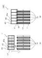
- Sectional drawing (A) which shows schematic structure of the injection type assembled battery which concerns on 1st Embodiment, and the assembled battery (after injection) formed using the injection type assembled battery which concerns on 1st Embodiment
- sectional drawing (B) which shows a schematic structure. It is an expanded sectional view showing the schematic structure of the electrode which constitutes the unit cell in the assembled battery (after pouring) formed using the injection type assembled battery concerning a 1st embodiment.
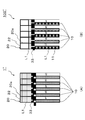
- Sectional drawing (A) which shows schematic structure of the injection type assembled battery which concerns on 2nd Embodiment, and the assembled battery (after injection) formed using the injection type assembled battery which concerns on 2nd Embodiment
- Sectional drawing (B) which shows a schematic structure.
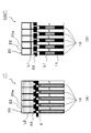
- Sectional drawing (A) which shows schematic structure of the injection type assembled battery which concerns on 3rd Embodiment, and the assembled battery (after injection) formed using the injection type assembled battery which concerns on 3rd Embodiment It is sectional drawing (B) which shows a schematic structure.
- Sectional drawing (A) which shows schematic structure of the injection type assembled battery which concerns on 4th Embodiment, and the assembled battery (after injection) formed using the injection type assembled battery which concerns on 4th Embodiment It is sectional drawing (B) which shows a schematic structure.
- injection type assembled battery forms an assembled battery by injecting the liquid which comprises electrolyte with respect to the several electrode accommodating part which accommodates the electrode which comprises a single battery. Say what you can. Accordingly, in the present application, the “assembled battery” is formed using a liquid injection type battery (after liquid injection).
- the injection type assembled battery according to one embodiment of the present invention includes a plurality of electrode storage portions that store electrodes constituting a single battery, a liquid storage tank that stores a liquid that constitutes an electrolyte, and the liquid that is stored in the liquid storage tank.
- the liquid storage tank has a plurality of liquid storage portions provided by partition walls, and each of the liquid storage portions stores liquid to be injected into each of the electrode storage portions.
- the air battery described in Patent Document 1 and Japanese Patent Application Laid-Open No. 2002-151167 has a secondary advantage that a liquid junction, for which sufficient measures have not been taken, can be completely prevented.
- the liquid constituting the electrolyte is injected into the plurality of electrode housing portions that house the electrodes constituting the unit cell, thereby achieving an embodiment of the present invention.
- An assembled battery (after injecting) formed using such an injectable battery can be formed.
- the liquid injection type assembled battery of this embodiment includes a unit cell constituted by an electrode housed in one electrode housing portion and a unit cell constituted by an electrode housed in another electrode housing portion. It is preferable to have a structure that is connected in series. When the cells have a structure in which the cells are electrically connected in series, the output voltage can be further increased as compared with the case of parallel connection.
- the liquid constituting the electrolyte is injected into the plurality of electrode storage portions for storing the electrodes constituting the unit cell, thereby making one embodiment of the present invention.
- the assembled battery (after injecting) formed using the injection type assembled battery according to the above can be formed.
- the liquid injection type assembled battery of the present embodiment has a structure in which the liquid injection control unit can collectively inject liquid stored in the liquid storage tank into the electrode storage unit.
- the liquid injection control unit can collectively inject liquid stored in the liquid storage tank into the electrode storage unit.
- the injection type assembled battery of this embodiment has the structure where the positive electrode accommodated in one electrode accommodating part and the negative electrode accommodated in the other electrode accommodating part adjacent to one electrode accommodating part oppose. It is preferable.
- the positive electrode and the negative electrode have a structure in which the positive electrode and the negative electrode are opposed to each other, it is possible to further reduce the size around the battery housing portion such as a current collector, and to further increase the output per volume.
- the liquid constituting the electrolyte is injected into the plurality of electrode storage portions for storing the electrodes constituting the unit cell, thereby making one embodiment of the present invention.
- the assembled battery (after injecting) formed using the injection type assembled battery according to the above can be formed.
- the liquid storage tank may have an integrated structure or a separate structure with the electrode storage portion. If the liquid storage tank has an integral structure with the electrode storage section, there is an advantage that it is not necessary to attach the liquid storage tank to the electrode storage section during liquid injection. On the other hand, when the liquid storage tank has a separate structure from the electrode storage section, it is necessary to attach the liquid storage tank to the electrode storage section when injecting, but there is an advantage that it can be stored separately until necessary. is there.
- the liquid constituting the electrolyte is injected into the plurality of electrode storage portions for storing the electrodes constituting the unit cell, thereby making one embodiment of the present invention.
- the assembled battery (after injecting) formed using the injection type assembled battery according to the above can be formed.
- the injection type assembled battery of this embodiment is a structure which can remove a liquid storage tank.
- the liquid storage tank has a removable structure, the assembled battery itself can be reduced in size by removing the liquid storage tank after injecting liquid to form the assembled battery, and the output per volume can be increased. Can do.
- the liquid constituting the electrolyte is injected into the plurality of electrode storage portions for storing the electrodes constituting the unit cell, thereby making one embodiment of the present invention.
- the assembled battery (after injecting) formed using the injection type assembled battery according to the above can be formed.
- the liquid is preferably an electrolyte or a solvent that contains an electrolyte salt and becomes an electrolyte.
- the liquid is the electrolyte solution itself, there is an advantage that a liquid (electrolyte solution) having a uniform concentration prepared in advance can be supplied to the electrode housing portion.
- the liquid is a solvent that contains an electrolyte salt and becomes an electrolytic solution, the liquid can be stored in a neutral state, and thus there is an advantage that the degree of freedom in material design of the liquid storage tank is increased.
- the liquid constituting the electrolyte is injected into the plurality of electrode storage portions for storing the electrodes constituting the unit cell, thereby making one embodiment of the present invention.
- the assembled battery (after injecting) formed using the injection type assembled battery according to the above can be formed.
- FIG. 1A is a cross-sectional view showing a schematic configuration of the injection type assembled battery according to the first embodiment, and FIG. 1B is formed using the injection type assembled battery according to the first embodiment. It is sectional drawing which shows schematic structure of an assembled battery (after pouring).
- the injection type assembled battery 1 according to the present embodiment includes a plurality of electrode storage portions 10 that store electrodes constituting a single battery, and an electrolytic solution L1 that is a kind of liquid that constitutes an electrolyte.
- a liquid storage tank 20 to be stored, and an individually controllable valve 31 that is a kind of liquid injection control means for injecting the electrolyte L1 stored in the liquid storage tank 20 into the electrode storage unit 10. is there.
- the liquid storage tank 20 has the some liquid storage part 22 demarcated by the partition 20a, and each liquid storage part 22 stores the electrolyte solution L1 injected with respect to each electrode storage part 10 each. Is.
- the assembled battery 100 formed using the injectable battery assembly according to the present embodiment can be formed.
- the assembled battery 100 includes a single battery 11.
- the liquid injection type assembled battery according to the present embodiment has a plurality of liquid storage portions that store liquid injected into each of the electrode storage portions, so that the amount of liquid injected into each of the battery storage portions varies. It can be suppressed and the output can be improved. Moreover, since the liquid storage tank and the electrode storage part have an integral structure, the liquid injection type assembled battery of this embodiment has an advantage that it is not necessary to attach the liquid storage tank to the electrode storage part at the time of liquid injection. Although not shown, since the liquid storage tank has a removable structure, the assembled battery itself can be reduced in size and the output per volume can be further increased.
- the injection type assembled battery of this embodiment has a structure in which the cells are electrically connected in series by a current collector (not shown), the output voltage is made higher than in the case of parallel connection. Can do.
- the injection type assembled battery of the present embodiment has a structure in which the positive electrode of the unit cell and the negative electrode of another unit cell adjacent to the unit cell are opposed to each other. The size can be reduced, and the output per volume can be further increased.
- the injection type assembled battery of this embodiment uses electrolyte solution itself as a liquid, there exists an advantage that the liquid (electrolyte solution) by which the density
- the assembled battery (after injecting) formed using the injecting type assembled battery of the present embodiment has improved output.
- the electrode storage unit 10, the liquid storage tank 20, the partition wall 20a, and the valve 31 are formed of a plastic material such as hard vinyl chloride.
- the electrolytic solution is a solution such as an aqueous solution of potassium chloride, sodium chloride, potassium hydroxide or the like.
- the material is not particularly limited as long as it can withstand the corrosion of a strong alkaline electrolyte, and a material used in a conventionally known air battery can be applied.
- FIG. 2 is an enlarged cross-sectional view showing a schematic configuration of electrodes constituting a unit cell in an assembled battery (after injection) formed using the injected type assembled battery according to the first embodiment.
- the unit cell 11 has a configuration in which a negative electrode layer 11A, a separator layer 11B, and a positive electrode layer 11C are stacked.
- the electrolytic solution L1 is injected into the single battery 11.
- the water repellent layer 11 ⁇ / b> D forms a boundary portion with the air flow path AP in the electrode housing portion 10.
- the negative electrode layer 11A is made of, for example, magnesium, zinc, aluminum, a magnesium alloy, a zinc alloy, an aluminum alloy, but is not limited thereto, and a negative electrode material used in a conventionally known air battery is applied. be able to.
- the separator layer 11B is made of, for example, a water-absorbing material such as glass paper that has not been subjected to water repellent treatment, but is not limited thereto, and a separator material used in a conventionally known air battery is applied. Can do.
- the positive electrode layer 11C is made of, for example, a porous material containing petroleum-based graphite powder as a main component, but is not limited thereto, and a positive electrode material used in a conventionally known air battery can be applied. it can.
- an olefin resin such as polyethylene or polypropylene, or a fluorine resin such as polytetrafluoroethylene or polyvinylidene fluoride can be applied.
- the material is not limited thereto, and any conventionally known material can be appropriately used as long as it can suppress leakage of the electrolyte and at least transmit oxygen.
- FIG. 3A is a cross-sectional view showing a schematic configuration of the injection type assembled battery according to the second embodiment
- FIG. 3B is formed using the injection type assembled battery according to the second embodiment.
- It is sectional drawing which shows schematic structure of an assembled battery (after pouring).
- symbol same as them is attached
- subjected and description is abbreviate
- the liquid injection type assembled battery 1 ′ according to the present embodiment has a configuration in which the liquid injection control means is a tubular piercing means 32 provided in the electrode housing portion. This is different from the injection type assembled battery according to the above.
- the tubular piercing means 32 By injecting liquid in an open state by the tubular piercing means 32, an assembled battery 100 ′ formed using the injectable battery according to the present embodiment can be formed.
- the assembled battery 100 ′ has a single battery 11.
- the liquid injection type assembled battery according to the present embodiment has a plurality of liquid storage portions that store liquid injected into each of the electrode storage portions, so that the amount of liquid injected into each of the battery storage portions varies. It can be suppressed and the output can be improved. Moreover, since the liquid storage tank and the electrode storage part are separate structures in the liquid injection type assembled battery of this embodiment, it is necessary to attach the liquid storage tank to the electrode storage part when injecting, There is an advantage that it can be stored separately. Furthermore, since the injection type assembled battery of this embodiment has a structure in which the cells are electrically connected in series by a current collector (not shown), the output voltage is made higher than in the case of parallel connection. Can do.
- the injection type assembled battery of the present embodiment has a structure in which the positive electrode of the unit cell and the negative electrode of another unit cell adjacent to the unit cell are opposed to each other. The size can be reduced, and the output per volume can be further increased.
- the liquid injection control means is a tubular piercing means, and the liquid stored in the liquid storage tank can be collectively injected into the electrode storage portion. The electrolyte solution can be simultaneously injected into each electrode storage portion that stores the electrode. Therefore, a side reaction (gas generation) in the unit cell is suppressed, and the life of the assembled battery can be improved.
- having a structure capable of batch injection has an advantage that handling becomes easier as compared with a single cell assembly.
- the injection type assembled battery of this embodiment uses the electrolyte solution itself as the liquid, there is an advantage that a liquid (electrolyte solution) having a uniform concentration prepared in advance can be supplied to the electrodes. .
- the assembled battery (after injecting) formed using the injecting type assembled battery of the present embodiment has improved output.
- FIG. 4A is a cross-sectional view showing a schematic configuration of the injection type assembled battery according to the third embodiment
- FIG. 4B is formed using the injection type assembled battery according to the third embodiment.
- It is sectional drawing which shows schematic structure of an assembled battery (after pouring).
- symbol same as them is attached
- subjected and description is abbreviate
- the liquid injection type assembled battery 1 ′′ according to the present embodiment has a configuration in which the liquid injection control means is a slide type integrated valve 33 provided in the electrode storage portion. This is different from the injection type assembled battery according to the embodiment.
- the liquid injection control means is a slide type integrated valve 33 provided in the electrode storage portion.
- the slide-type integrated valve 33 By injecting the liquid in an open state by the slide-type integrated valve 33, it is possible to form an assembled battery 100 '' formed using the injectable battery according to the present embodiment.
- the assembled battery 100 ′′ has a single battery 11.
- the liquid injection type assembled battery according to the present embodiment has a plurality of liquid storage portions that store liquid injected into each of the electrode storage portions, so that the amount of liquid injected into each of the battery storage portions varies. It can be suppressed and the output can be improved. Moreover, since the liquid storage tank and the electrode storage part have an integral structure, the liquid injection type assembled battery of this embodiment has an advantage that it is not necessary to attach the liquid storage tank to the electrode storage part at the time of liquid injection. Although not shown, since the liquid storage tank has a removable structure, the assembled battery itself can be reduced in size and the output per volume can be further increased.
- the injection type assembled battery of this embodiment has a structure in which the cells are electrically connected in series by a current collector (not shown), the output voltage is made higher than in the case of parallel connection. Can do.
- the injection type assembled battery of the present embodiment has a structure in which the positive electrode of the unit cell and the negative electrode of another unit cell adjacent to the unit cell are opposed to each other. The size can be reduced, and the output per volume can be further increased.
- the liquid injection type assembled battery of this embodiment is a structure in which the liquid injection control means is a slide type integrated valve, and the liquid stored in the liquid storage tank can be collectively injected into the electrode storage portion. The electrolyte solution can be simultaneously injected into each electrode storage portion that stores the unit cell.
- the injection type assembled battery of this embodiment uses the electrolyte solution itself as the liquid, there is an advantage that a liquid (electrolyte solution) having a uniform concentration prepared in advance can be supplied to the electrodes. .
- the assembled battery (after injecting) formed using the injecting type assembled battery of the present embodiment has improved output.
- FIG. 5A is a cross-sectional view showing a schematic configuration of the injection type assembled battery according to the fourth embodiment
- FIG. 5B is formed using the injection type assembled battery according to the fourth embodiment.
- It is sectional drawing which shows schematic structure of an assembled battery (after pouring). Note that the same components as those described in the first to third embodiments are denoted by the same reference numerals, and description thereof is omitted.
- the injection type assembled battery 1 ′ ′′ according to the present embodiment includes an electrolyte salt E and a solvent type L 2 that contains the electrolyte salt E and becomes the electrolyte L 1 separately.
- the structure in which the electrolyte salt E and the solvent L2 are mixed to prepare the electrolyte L1 is different from the injection type assembled battery according to the third embodiment.
- An assembled battery formed by using the injection type assembled battery according to the present embodiment by injecting an electrolyte prepared by mixing an electrolyte salt and a solvent while being opened by the slide type integrated valve 33 100 ′ ′′ can be formed.
- the assembled battery 100 ′ ′′ includes the single battery 11.
- the liquid injection type assembled battery according to the present embodiment has a plurality of liquid storage portions that store liquid injected into each of the electrode storage portions, so that the amount of liquid injected into each of the battery storage portions varies. It can be suppressed and the output can be improved. Moreover, since the liquid storage tank and the electrode storage part have an integral structure, the liquid injection type assembled battery of this embodiment has an advantage that it is not necessary to attach the liquid storage tank to the electrode storage part at the time of liquid injection. Although not shown, since the liquid storage tank has a removable structure, the assembled battery itself can be reduced in size and the output per volume can be further increased.
- the injection type assembled battery of this embodiment has a structure in which the cells are electrically connected in series by a current collector (not shown), the output voltage is made higher than in the case of parallel connection. Can do.
- the injection type assembled battery of the present embodiment has a structure in which the positive electrode of the unit cell and the negative electrode of another unit cell adjacent to the unit cell are opposed to each other. The size can be reduced, and the output per volume can be further increased.
- the liquid injection type assembled battery of this embodiment is a structure in which the liquid injection control means is a slide type integrated valve, and the liquid stored in the liquid storage tank can be collectively injected into the electrode storage portion. The electrolyte solution can be simultaneously injected into each electrode storage portion that stores the unit cell.
- the injection type assembled battery of the present embodiment uses a solvent that contains an electrolyte salt and becomes an electrolytic solution as a liquid, the liquid can be stored in a neutral state. There is an advantage that the degree of freedom in material design is increased.
- the assembled battery (after injecting) formed using the injecting type assembled battery of the present embodiment has improved output.
- each of the above-described embodiments is not necessarily limited to each embodiment.
- an electrolyte salt and a solvent that includes the electrolyte salt and becomes an electrolyte solution are separately injected type assembled batteries.
- the configuration included in any of the embodiments can be employed.
- Electrode storage portion 1 Single cell 11A Negative electrode layer 11B Separator layer 11C Positive electrode layer 11D Water repellent layer 20 Liquid storage tank 20a Partition wall 22 Liquid storage portion 31 Valve 32 Tubular puncture means 33 Sliding integrated valve 100, 100 ′, 100 ′′, 100 ′ ′′ Battery pack E Electrolyte salt L1 Electrolytic solution L2 Solvent AP Air flow path
Landscapes
- Chemical & Material Sciences (AREA)
- Chemical Kinetics & Catalysis (AREA)
- Electrochemistry (AREA)
- General Chemical & Material Sciences (AREA)
- Filling, Topping-Up Batteries (AREA)
Abstract
電極収容部各々への注液量がばらつくことを抑制し、出力を向上し得る注液式組電池を提供する。 注液式組電池は、単電池を構成する電極を収納する複数の電極収納部と、電解質を構成する液体を貯留する液体貯留槽と、該液体貯留槽に貯留される該液体を該電極収納部に注液する注液制御手段とを備える。該液体貯留槽は、隔壁により画設された複数の液体貯留部を有し、該液体貯留部各々は、該電極収容部各々に対して注液される該液体を貯留する。
Description
本発明は、注液式組電池に関する。
更に詳細には、本発明は、電池収納部各々への注液量がばらつくことを抑制し、出力を向上し得る注液式組電池に関する。
更に詳細には、本発明は、電池収納部各々への注液量がばらつくことを抑制し、出力を向上し得る注液式組電池に関する。
従来、アルカリ固型板の固定を計り亜鉛極の挿入操作を容易に行わしめると共に仕切板をアルカリ固型板形成用の金型として利用するために、対向側面に夫々空気極を取付けた電槽内を、両側面に形設した凹所に溶融アルカリを充填、固化してなる仕切板により区割し、各区割室に亜鉛極を夫々介挿してなる注液式空気-亜鉛電池が提案されている(特許文献1参照。)。
しかしながら、上記特許文献1に記載された注液式空気-亜鉛電池にあっては、貯水槽が1つであり、各区割室の注液量がばらつくことがあるため、出力が十分なものとなっていないという問題点があった。
本発明は、このような従来技術の有する課題に鑑みてなされたものである。
そして、本発明の目的とするところは、電池収納部各々への注液量がばらつくことを抑制し、出力を向上し得る注液式組電池を提供することにある。
そして、本発明の目的とするところは、電池収納部各々への注液量がばらつくことを抑制し、出力を向上し得る注液式組電池を提供することにある。
本発明者らは上記目的を達成するため鋭意検討を重ねた。
そして、その結果、液体貯留槽内を隔壁により画設して、電極収納部各々に対して注液される液体を貯留する液体貯留部を複数有する構成とすることにより、上記目的が達成できることを見出し、本発明を完成するに至った。
そして、その結果、液体貯留槽内を隔壁により画設して、電極収納部各々に対して注液される液体を貯留する液体貯留部を複数有する構成とすることにより、上記目的が達成できることを見出し、本発明を完成するに至った。
すなわち、本発明の注液式組電池は、単電池を構成する電極を収納する複数の電極収納部と、電解質を構成する液体を貯留する液体貯留槽と、該液体貯留槽に貯留される該液体を該電極収納部に注液する注液制御手段とを備えるものである。
そして、上記液体貯留槽は、隔壁により画設された複数の液体貯留部を有し、上記液体貯留部各々は、上記電極収納部各々に対して注液される上記液体を貯留するものである。
そして、上記液体貯留槽は、隔壁により画設された複数の液体貯留部を有し、上記液体貯留部各々は、上記電極収納部各々に対して注液される上記液体を貯留するものである。
本発明によれば、液体貯留槽内を隔壁により画設して、電極収納部各々に対して注液される液体を貯留する液体貯留部を複数有する構成とした。そのため、電池収納部各々への注液量がばらつくことを抑制し、出力を向上し得る注液式組電池を提供することができる。
以下、本発明の注液式組電池について詳細に説明する。
なお、本願において、「注液式組電池」とは、単電池を構成する電極を収納する複数の電極収納部に対して、電解質を構成する液体を注液することにより、組電池を形成することができるものをいう。従って、本願において、「組電池」とは、注液式組電池を用いて形成されるもの(注液後)である。
なお、本願において、「注液式組電池」とは、単電池を構成する電極を収納する複数の電極収納部に対して、電解質を構成する液体を注液することにより、組電池を形成することができるものをいう。従って、本願において、「組電池」とは、注液式組電池を用いて形成されるもの(注液後)である。
本発明の一実施形態に係る注液式組電池について詳細に説明する。
本実施形態の注液式組電池は、単電池を構成する電極を収納する複数の電極収納部と、電解質を構成する液体を貯留する液体貯留槽と、該液体貯留槽に貯留される該液体を該電極収納部に注液する注液制御手段とを備えるものである。
そして、液体貯留槽は、隔壁により画設された複数の液体貯留部を有し、液体貯留部各々は、電極収納部各々に対して注液される液体を貯留するものである。
このような構成とすることにより、電池収納部各々への注液量がばらつくことを抑制し、出力を向上し得る注液式組電池を得ることができる。また、上記特許文献1や特開2002-151167号公報に記載の空気電池においては、十分な対策がなされていなかった液絡を完全に防止し得るという副次的な利点もある。
なお、本実施形態の注液式組電池において、単電池を構成する電極を収納する複数の電極収納部に対して、電解質を構成する液体を注液することにより、本発明の一実施形態に係る注液式組電池を用いて形成した組電池(注液後)を形成することができる。
本実施形態の注液式組電池は、単電池を構成する電極を収納する複数の電極収納部と、電解質を構成する液体を貯留する液体貯留槽と、該液体貯留槽に貯留される該液体を該電極収納部に注液する注液制御手段とを備えるものである。
そして、液体貯留槽は、隔壁により画設された複数の液体貯留部を有し、液体貯留部各々は、電極収納部各々に対して注液される液体を貯留するものである。
このような構成とすることにより、電池収納部各々への注液量がばらつくことを抑制し、出力を向上し得る注液式組電池を得ることができる。また、上記特許文献1や特開2002-151167号公報に記載の空気電池においては、十分な対策がなされていなかった液絡を完全に防止し得るという副次的な利点もある。
なお、本実施形態の注液式組電池において、単電池を構成する電極を収納する複数の電極収納部に対して、電解質を構成する液体を注液することにより、本発明の一実施形態に係る注液式組電池を用いて形成した組電池(注液後)を形成することができる。
また、本実施形態の注液式組電池は、一の電極収納部に収納された電極によって構成される単電池と他の電極収納部に収納された電極によって構成される単電池とが、電気的に直列接続となる構造を有することが好ましい。
上記単電池同士が電気的に直列接続となる構造を有すると、並列接続の場合と比較して、出力電圧をより高くすることができる。
なお、本実施形態の注液式組電池においても、単電池を構成する電極を収納する複数の電極収納部に対して、電解質を構成する液体を注液することにより、本発明の一実施形態に係る注液式組電池を用いて形成した組電池(注液後)を形成することができる。
上記単電池同士が電気的に直列接続となる構造を有すると、並列接続の場合と比較して、出力電圧をより高くすることができる。
なお、本実施形態の注液式組電池においても、単電池を構成する電極を収納する複数の電極収納部に対して、電解質を構成する液体を注液することにより、本発明の一実施形態に係る注液式組電池を用いて形成した組電池(注液後)を形成することができる。
更に、本実施形態の注液式組電池は、注液制御手段が、液体貯留槽が貯留する液体を電極収納部に一括注液可能な構造を有することが好ましい。
このような構成とすることにより、各単電池を収納する各電極収納部に、電解液を同時に注液することができるため、単電池での副反応(ガス発生)が抑制され、組電池の寿命を向上させることができる。また、一括注液可能な構造を有すると、単電池の集合体である場合と比較して取扱いが容易となるという利点がある。
なお、本実施形態の注液式組電池においても、単電池を構成する電極を収納する複数の電極収納部に対して、電解質を構成する液体を注液することにより、本発明の一実施形態に係る注液式組電池を用いて形成した組電池(注液後)を形成することができる。
このような構成とすることにより、各単電池を収納する各電極収納部に、電解液を同時に注液することができるため、単電池での副反応(ガス発生)が抑制され、組電池の寿命を向上させることができる。また、一括注液可能な構造を有すると、単電池の集合体である場合と比較して取扱いが容易となるという利点がある。
なお、本実施形態の注液式組電池においても、単電池を構成する電極を収納する複数の電極収納部に対して、電解質を構成する液体を注液することにより、本発明の一実施形態に係る注液式組電池を用いて形成した組電池(注液後)を形成することができる。
また、本実施形態の注液式組電池は、一の電極収納部に収納された正極と一の電極収納部に隣接する他の電極収納部に収納された負極とが、対向する構造を有することが好ましい。上記正極と上記負極とが対向する構造を有すると、集電体などの電池収納部回りをより小型化することができ、体積当たりの出力をより高くすることができる。
なお、本実施形態の注液式組電池においても、単電池を構成する電極を収納する複数の電極収納部に対して、電解質を構成する液体を注液することにより、本発明の一実施形態に係る注液式組電池を用いて形成した組電池(注液後)を形成することができる。
なお、本実施形態の注液式組電池においても、単電池を構成する電極を収納する複数の電極収納部に対して、電解質を構成する液体を注液することにより、本発明の一実施形態に係る注液式組電池を用いて形成した組電池(注液後)を形成することができる。
更に、本実施形態の注液式組電池は、例えば液体貯留槽が電極収納部と一体型構造又は別体型構造であるものとすることができる。
液体貯留槽が電極収納部と一体型構造であると、注液に際して、液体貯留槽を電極収納部に取り付ける必要がないという利点がある。一方、液体貯留槽が電極収納部と別体型構造であると、注液に際して、液体貯留槽を電極収納部に取り付ける必要はあるものの、必要時まで別々に保管することが可能であるという利点がある。
なお、本実施形態の注液式組電池においても、単電池を構成する電極を収納する複数の電極収納部に対して、電解質を構成する液体を注液することにより、本発明の一実施形態に係る注液式組電池を用いて形成した組電池(注液後)を形成することができる。
液体貯留槽が電極収納部と一体型構造であると、注液に際して、液体貯留槽を電極収納部に取り付ける必要がないという利点がある。一方、液体貯留槽が電極収納部と別体型構造であると、注液に際して、液体貯留槽を電極収納部に取り付ける必要はあるものの、必要時まで別々に保管することが可能であるという利点がある。
なお、本実施形態の注液式組電池においても、単電池を構成する電極を収納する複数の電極収納部に対して、電解質を構成する液体を注液することにより、本発明の一実施形態に係る注液式組電池を用いて形成した組電池(注液後)を形成することができる。
また、本実施形態の注液式組電池は、液体貯留槽が取り外し可能な構造であることが好ましい。
液体貯留槽が取り外し可能な構造であると、注液して組電池を形成した後に液体貯留槽を取り外すことによって、組電池自体を小型化することができ、体積当たりの出力をより高くすることができる。
なお、本実施形態の注液式組電池においても、単電池を構成する電極を収納する複数の電極収納部に対して、電解質を構成する液体を注液することにより、本発明の一実施形態に係る注液式組電池を用いて形成した組電池(注液後)を形成することができる。
液体貯留槽が取り外し可能な構造であると、注液して組電池を形成した後に液体貯留槽を取り外すことによって、組電池自体を小型化することができ、体積当たりの出力をより高くすることができる。
なお、本実施形態の注液式組電池においても、単電池を構成する電極を収納する複数の電極収納部に対して、電解質を構成する液体を注液することにより、本発明の一実施形態に係る注液式組電池を用いて形成した組電池(注液後)を形成することができる。
更に、本実施形態の注液式組電池は、上記液体が電解液、又は電解質塩を含んで電解液となる溶媒であることが好ましい。
液体が電解液自体であると、予め濃度が均一に調製された液体(電解液)を電極収納部に供給することができるという利点がある。一方、液体が電解質塩を含んで電解液となる溶媒であると、液体を中性の状態で保管することができるため、液体貯留槽の材料設計の自由度が高くなるという利点がある。
なお、本実施形態の注液式組電池においても、単電池を構成する電極を収納する複数の電極収納部に対して、電解質を構成する液体を注液することにより、本発明の一実施形態に係る注液式組電池を用いて形成した組電池(注液後)を形成することができる。
液体が電解液自体であると、予め濃度が均一に調製された液体(電解液)を電極収納部に供給することができるという利点がある。一方、液体が電解質塩を含んで電解液となる溶媒であると、液体を中性の状態で保管することができるため、液体貯留槽の材料設計の自由度が高くなるという利点がある。
なお、本実施形態の注液式組電池においても、単電池を構成する電極を収納する複数の電極収納部に対して、電解質を構成する液体を注液することにより、本発明の一実施形態に係る注液式組電池を用いて形成した組電池(注液後)を形成することができる。
以下、本発明の若干の実施形態ついて図面を参照しながら詳細に説明する。
(第1の実施形態)
図1(A)は、第1の実施形態に係る注液式組電池の概略的な構成を示す断面図、(B)は第1の実施形態に係る注液式組電池を用いて形成した組電池(注液後)の概略的な構成を示す断面図である。
本実施形態に係る注液式組電池1は、図1に示すように、単電池を構成する電極を収納する複数の電極収納部10と、電解質を構成する液体の一種である電解液L1を貯留する液体貯留槽20と、該液体貯留槽20に貯留される電解液L1を該電極収納部10に注液する注液制御手段の一種である個別に制御可能な弁31とを備えるものである。
そして、液体貯留槽20は、隔壁20aにより画設された複数の液体貯留部22を有し、液体貯留部22各々は、電極収納部10各々に対して注液される電解液L1を貯留するものである。
閉状態である弁31を開状態として注液することにより、本実施形態に係る注液式組電池を用いて形成した組電池100を形成することができる。なお、組電池100は単電池11を有する。
図1(A)は、第1の実施形態に係る注液式組電池の概略的な構成を示す断面図、(B)は第1の実施形態に係る注液式組電池を用いて形成した組電池(注液後)の概略的な構成を示す断面図である。
本実施形態に係る注液式組電池1は、図1に示すように、単電池を構成する電極を収納する複数の電極収納部10と、電解質を構成する液体の一種である電解液L1を貯留する液体貯留槽20と、該液体貯留槽20に貯留される電解液L1を該電極収納部10に注液する注液制御手段の一種である個別に制御可能な弁31とを備えるものである。
そして、液体貯留槽20は、隔壁20aにより画設された複数の液体貯留部22を有し、液体貯留部22各々は、電極収納部10各々に対して注液される電解液L1を貯留するものである。
閉状態である弁31を開状態として注液することにより、本実施形態に係る注液式組電池を用いて形成した組電池100を形成することができる。なお、組電池100は単電池11を有する。
本実施形態の注液式組電池は、電極収納部各々に対して注液される液体を貯留する液体貯留部を複数有する構成であるため、電池収納部各々への注液量がばらつくことを抑制し、出力を向上し得る。
また、本実施形態の注液式組電池は、液体貯留槽と電極収納部とが一体型構造であるため、注液に際して、液体貯留槽を電極収納部に取り付ける必要がないという利点がある。なお、図示しないが液体貯留槽が取り外し可能な構造であるため、組電池自体を小型化することができ、体積当たりの出力をより高くすることができる。
更に、本実施形態の注液式組電池は、図示しない集電体により単電池が電気的に直列接続となる構造を有するため、並列接続の場合と比較して、出力電圧をより高くすることができる。
また、本実施形態の注液式組電池は、単電池の正極とその単電池と隣り合う他の単電池の負極とが対向する構造を有するため、集電体などの電池収納部回りをより小型化することができ、体積当たりの出力をより高くすることができる。
更に、本実施形態の注液式組電池は、液体として電解液自体を用いているため、予め濃度が均一に調製された液体(電解液)を電極に供給することができるという利点がある。
本実施形態の注液式組電池を用いて形成される組電池(注液後)は、出力が向上したものとなる。
また、本実施形態の注液式組電池は、液体貯留槽と電極収納部とが一体型構造であるため、注液に際して、液体貯留槽を電極収納部に取り付ける必要がないという利点がある。なお、図示しないが液体貯留槽が取り外し可能な構造であるため、組電池自体を小型化することができ、体積当たりの出力をより高くすることができる。
更に、本実施形態の注液式組電池は、図示しない集電体により単電池が電気的に直列接続となる構造を有するため、並列接続の場合と比較して、出力電圧をより高くすることができる。
また、本実施形態の注液式組電池は、単電池の正極とその単電池と隣り合う他の単電池の負極とが対向する構造を有するため、集電体などの電池収納部回りをより小型化することができ、体積当たりの出力をより高くすることができる。
更に、本実施形態の注液式組電池は、液体として電解液自体を用いているため、予め濃度が均一に調製された液体(電解液)を電極に供給することができるという利点がある。
本実施形態の注液式組電池を用いて形成される組電池(注液後)は、出力が向上したものとなる。
上記電極収納部10や液体貯留槽20、隔壁20a、弁31は、例えば硬質塩化ビニール等のプラスチック材料で形成されている。通常、電解液は塩化カリウムや塩化ナトリウム、水酸化カリウムなどの水溶液などの溶液である。例えば、強アルカリ性である電解液の腐食に耐え得るものであれば、特に限定されるものではなく、従来公知の空気電池に用いられる材料を適用することができる。
図2は、第1の実施形態に係る注液式組電池を用いて形成した組電池(注液後)における単電池を構成する電極の概略的な構成を示す拡大断面図である。
図2に示すように、単電池11は、負極層11Aとセパレータ層11Bと正極層11Cが積層された構成を有している。また、単電池11には、電解液L1が注液されている。なお、撥水層11Dは電極収納部10において空気流路APとの境界部を形成している。
負極層11Aは、例えば、マグネシウム、亜鉛、アルミニウム、マグネシウム合金、亜鉛合金、アルミニウム合金などにより構成されるが、これらに限定されるものではなく、従来公知の空気電池に用いられる負極材料を適用することができる。
セパレータ層11Bは、例えば、撥水処理を行っていないグラスペーパー等の吸水性材料により構成されるが、これに限定されるものではなく、従来公知の空気電池に用いられるセパレータ材料を適用することができる。
正極層11Cは、例えば、石油系黒鉛粉末を主成分として含む多孔質のものにより構成されるが、これに限定されるものではなく、従来公知の空気電池に用いられる正極材料を適用することができる。
撥水層11Dは、例えば、ポリエチレンやポリプロピレンなどのオレフィン系樹脂やポリテトラフルオロエチレンやポリフッ化ビニリデンなどのフッ素系樹脂などを適用することができる。しかしながら、これらに限定されるものではなく、電解液の漏液を抑制し、少なくとも酸素を透過し得るものであれば、従来公知の材料を適宜用いることができる。
図2に示すように、単電池11は、負極層11Aとセパレータ層11Bと正極層11Cが積層された構成を有している。また、単電池11には、電解液L1が注液されている。なお、撥水層11Dは電極収納部10において空気流路APとの境界部を形成している。
負極層11Aは、例えば、マグネシウム、亜鉛、アルミニウム、マグネシウム合金、亜鉛合金、アルミニウム合金などにより構成されるが、これらに限定されるものではなく、従来公知の空気電池に用いられる負極材料を適用することができる。
セパレータ層11Bは、例えば、撥水処理を行っていないグラスペーパー等の吸水性材料により構成されるが、これに限定されるものではなく、従来公知の空気電池に用いられるセパレータ材料を適用することができる。
正極層11Cは、例えば、石油系黒鉛粉末を主成分として含む多孔質のものにより構成されるが、これに限定されるものではなく、従来公知の空気電池に用いられる正極材料を適用することができる。
撥水層11Dは、例えば、ポリエチレンやポリプロピレンなどのオレフィン系樹脂やポリテトラフルオロエチレンやポリフッ化ビニリデンなどのフッ素系樹脂などを適用することができる。しかしながら、これらに限定されるものではなく、電解液の漏液を抑制し、少なくとも酸素を透過し得るものであれば、従来公知の材料を適宜用いることができる。
(第2の実施形態)
図3(A)は、第2の実施形態に係る注液式組電池の概略的な構成を示す断面図、(B)は第2の実施形態に係る注液式組電池を用いて形成した組電池(注液後)の概略的な構成を示す断面図である。なお、第1の実施形態において説明したものと同等のものについては、それらと同一の符号を付して説明を省略する。
図3(A)は、第2の実施形態に係る注液式組電池の概略的な構成を示す断面図、(B)は第2の実施形態に係る注液式組電池を用いて形成した組電池(注液後)の概略的な構成を示す断面図である。なお、第1の実施形態において説明したものと同等のものについては、それらと同一の符号を付して説明を省略する。
図3に示すように、本実施形態に係る注液式組電池1’は、注液制御手段が電極収納部に設けられた管状の突刺手段32となっている構成が、第1の実施形態に係る注液式組電池と相違している。
管状の突刺手段32により開状態として注液することにより、本実施形態に係る注液式組電池を用いて形成した組電池100’を形成することができる。なお、組電池100’は単電池11を有する。
管状の突刺手段32により開状態として注液することにより、本実施形態に係る注液式組電池を用いて形成した組電池100’を形成することができる。なお、組電池100’は単電池11を有する。
本実施形態の注液式組電池は、電極収納部各々に対して注液される液体を貯留する液体貯留部を複数有する構成であるため、電池収納部各々への注液量がばらつくことを抑制し、出力を向上し得る。
また、本実施形態の注液式組電池は、液体貯留槽と電極収納部とが別体型構造であるため、注液に際して、液体貯留槽を電極収納部に取り付ける必要はあるが、必要時まで別々に保管することが可能であるという利点がある。
更に、本実施形態の注液式組電池は、図示しない集電体により単電池が電気的に直列接続となる構造を有するため、並列接続の場合と比較して、出力電圧をより高くすることができる。
また、本実施形態の注液式組電池は、単電池の正極とその単電池と隣り合う他の単電池の負極とが対向する構造を有するため、集電体などの電池収納部回りをより小型化することができ、体積当たりの出力をより高くすることができる。
更に、本実施形態の注液式組電池は、注液制御手段が管状の突刺手段であり、液体貯留槽が貯留する液体を電極収納部に一括注液可能な構造であるため、各単電池を収納する各電極収納部に電解液を同時に注液することができる。そのため、単電池での副反応(ガス発生)が抑制され、組電池の寿命を向上させることができる。また、一括注液可能な構造を有すると、単電池の集合体と比較して取扱いが容易となるという利点がある。
更にまた、本実施形態の注液式組電池は、液体として電解液自体を用いているため、予め濃度が均一に調製された液体(電解液)を電極に供給することができるという利点がある。
本実施形態の注液式組電池を用いて形成される組電池(注液後)は、出力が向上したものとなる。
また、本実施形態の注液式組電池は、液体貯留槽と電極収納部とが別体型構造であるため、注液に際して、液体貯留槽を電極収納部に取り付ける必要はあるが、必要時まで別々に保管することが可能であるという利点がある。
更に、本実施形態の注液式組電池は、図示しない集電体により単電池が電気的に直列接続となる構造を有するため、並列接続の場合と比較して、出力電圧をより高くすることができる。
また、本実施形態の注液式組電池は、単電池の正極とその単電池と隣り合う他の単電池の負極とが対向する構造を有するため、集電体などの電池収納部回りをより小型化することができ、体積当たりの出力をより高くすることができる。
更に、本実施形態の注液式組電池は、注液制御手段が管状の突刺手段であり、液体貯留槽が貯留する液体を電極収納部に一括注液可能な構造であるため、各単電池を収納する各電極収納部に電解液を同時に注液することができる。そのため、単電池での副反応(ガス発生)が抑制され、組電池の寿命を向上させることができる。また、一括注液可能な構造を有すると、単電池の集合体と比較して取扱いが容易となるという利点がある。
更にまた、本実施形態の注液式組電池は、液体として電解液自体を用いているため、予め濃度が均一に調製された液体(電解液)を電極に供給することができるという利点がある。
本実施形態の注液式組電池を用いて形成される組電池(注液後)は、出力が向上したものとなる。
(第3の実施形態)
図4(A)は、第3の実施形態に係る注液式組電池の概略的な構成を示す断面図、(B)は第3の実施形態に係る注液式組電池を用いて形成した組電池(注液後)の概略的な構成を示す断面図である。なお、第1又は第2の実施形態において説明したものと同等のものについては、それらと同一の符号を付して説明を省略する。
図4(A)は、第3の実施形態に係る注液式組電池の概略的な構成を示す断面図、(B)は第3の実施形態に係る注液式組電池を用いて形成した組電池(注液後)の概略的な構成を示す断面図である。なお、第1又は第2の実施形態において説明したものと同等のものについては、それらと同一の符号を付して説明を省略する。
図4に示すように、本実施形態に係る注液式組電池1’’は、注液制御手段が電極収納部に設けられたスライド式の一体型弁33となっている構成が、第1の実施形態に係る注液式組電池と相違している。
スライド式の一体型弁33により開状態として注液することにより、本実施形態に係る注液式組電池を用いて形成した組電池100’’を形成することができる。なお、組電池100’’は単電池11を有する。
スライド式の一体型弁33により開状態として注液することにより、本実施形態に係る注液式組電池を用いて形成した組電池100’’を形成することができる。なお、組電池100’’は単電池11を有する。
本実施形態の注液式組電池は、電極収納部各々に対して注液される液体を貯留する液体貯留部を複数有する構成であるため、電池収納部各々への注液量がばらつくことを抑制し、出力を向上し得る。
また、本実施形態の注液式組電池は、液体貯留槽と電極収納部とが一体型構造であるため、注液に際して、液体貯留槽を電極収納部に取り付ける必要がないという利点がある。なお、図示しないが液体貯留槽が取り外し可能な構造であるため、組電池自体を小型化することができ、体積当たりの出力をより高くすることができる。
更に、本実施形態の注液式組電池は、図示しない集電体により単電池が電気的に直列接続となる構造を有するため、並列接続の場合と比較して、出力電圧をより高くすることができる。
また、本実施形態の注液式組電池は、単電池の正極とその単電池と隣り合う他の単電池の負極とが対向する構造を有するため、集電体などの電池収納部回りをより小型化することができ、体積当たりの出力をより高くすることができる。
更に、本実施形態の注液式組電池は、注液制御手段がスライド式の一体型弁であり、液体貯留槽が貯留する液体を電極収納部に一括注液可能な構造であるため、各単電池を収納する各電極収納部に電解液を同時に注液することができる。そのため、単電池での副反応(ガス発生)が抑制され、組電池の寿命を向上させることができる。また、一括注液可能な構造を有すると、単電池の集合体と比較して取扱いが容易となるという利点がある。
更にまた、本実施形態の注液式組電池は、液体として電解液自体を用いているため、予め濃度が均一に調製された液体(電解液)を電極に供給することができるという利点がある。
本実施形態の注液式組電池を用いて形成される組電池(注液後)は、出力が向上したものとなる。
また、本実施形態の注液式組電池は、液体貯留槽と電極収納部とが一体型構造であるため、注液に際して、液体貯留槽を電極収納部に取り付ける必要がないという利点がある。なお、図示しないが液体貯留槽が取り外し可能な構造であるため、組電池自体を小型化することができ、体積当たりの出力をより高くすることができる。
更に、本実施形態の注液式組電池は、図示しない集電体により単電池が電気的に直列接続となる構造を有するため、並列接続の場合と比較して、出力電圧をより高くすることができる。
また、本実施形態の注液式組電池は、単電池の正極とその単電池と隣り合う他の単電池の負極とが対向する構造を有するため、集電体などの電池収納部回りをより小型化することができ、体積当たりの出力をより高くすることができる。
更に、本実施形態の注液式組電池は、注液制御手段がスライド式の一体型弁であり、液体貯留槽が貯留する液体を電極収納部に一括注液可能な構造であるため、各単電池を収納する各電極収納部に電解液を同時に注液することができる。そのため、単電池での副反応(ガス発生)が抑制され、組電池の寿命を向上させることができる。また、一括注液可能な構造を有すると、単電池の集合体と比較して取扱いが容易となるという利点がある。
更にまた、本実施形態の注液式組電池は、液体として電解液自体を用いているため、予め濃度が均一に調製された液体(電解液)を電極に供給することができるという利点がある。
本実施形態の注液式組電池を用いて形成される組電池(注液後)は、出力が向上したものとなる。
(第4の実施形態)
図5(A)は、第4の実施形態に係る注液式組電池の概略的な構成を示す断面図、(B)は第4の実施形態に係る注液式組電池を用いて形成した組電池(注液後)の概略的な構成を示す断面図である。なお、第1~第3の実施形態において説明したものと同等のものについては、それらと同一の符号を付して説明を省略する。
図5(A)は、第4の実施形態に係る注液式組電池の概略的な構成を示す断面図、(B)は第4の実施形態に係る注液式組電池を用いて形成した組電池(注液後)の概略的な構成を示す断面図である。なお、第1~第3の実施形態において説明したものと同等のものについては、それらと同一の符号を付して説明を省略する。
図5に示すように、本実施形態に係る注液式組電池1’’’は、電解質塩Eと、電解質塩Eを含んで電解液L1となる溶媒L2とが別個に注液式組電池に含まれており、注液に際して、電解質塩Eと溶媒L2とが混合されて電解液L1が調製される構成が、第3の実施形態に係る注液式組電池と相違している。
スライド式の一体型弁33により開状態として、電解質塩と溶媒とが混合されて調製された電解液を注液することにより、本実施形態に係る注液式組電池を用いて形成した組電池100’’’を形成することができる。なお、組電池100’’’は単電池11を有する。
スライド式の一体型弁33により開状態として、電解質塩と溶媒とが混合されて調製された電解液を注液することにより、本実施形態に係る注液式組電池を用いて形成した組電池100’’’を形成することができる。なお、組電池100’’’は単電池11を有する。
本実施形態の注液式組電池は、電極収納部各々に対して注液される液体を貯留する液体貯留部を複数有する構成であるため、電池収納部各々への注液量がばらつくことを抑制し、出力を向上し得る。
また、本実施形態の注液式組電池は、液体貯留槽と電極収納部とが一体型構造であるため、注液に際して、液体貯留槽を電極収納部に取り付ける必要がないという利点がある。なお、図示しないが液体貯留槽が取り外し可能な構造であるため、組電池自体を小型化することができ、体積当たりの出力をより高くすることができる。
更に、本実施形態の注液式組電池は、図示しない集電体により単電池が電気的に直列接続となる構造を有するため、並列接続の場合と比較して、出力電圧をより高くすることができる。
また、本実施形態の注液式組電池は、単電池の正極とその単電池と隣り合う他の単電池の負極とが対向する構造を有するため、集電体などの電池収納部回りをより小型化することができ、体積当たりの出力をより高くすることができる。
更に、本実施形態の注液式組電池は、注液制御手段がスライド式の一体型弁であり、液体貯留槽が貯留する液体を電極収納部に一括注液可能な構造であるため、各単電池を収納する各電極収納部に電解液を同時に注液することができる。そのため、単電池での副反応(ガス発生)が抑制され、組電池の寿命を向上させることができる。また、一括注液可能な構造を有すると、単電池の集合体と比較して取扱いが容易となるという利点がある。
更にまた、本実施形態の注液式組電池は、液体として、電解質塩を含んで電解液となる溶媒を用いているため、液体を中性の状態で保管することができ、液体貯留槽の材料設計の自由度が高くなるという利点がある。
本実施形態の注液式組電池を用いて形成される組電池(注液後)は、出力が向上したものとなる。
また、本実施形態の注液式組電池は、液体貯留槽と電極収納部とが一体型構造であるため、注液に際して、液体貯留槽を電極収納部に取り付ける必要がないという利点がある。なお、図示しないが液体貯留槽が取り外し可能な構造であるため、組電池自体を小型化することができ、体積当たりの出力をより高くすることができる。
更に、本実施形態の注液式組電池は、図示しない集電体により単電池が電気的に直列接続となる構造を有するため、並列接続の場合と比較して、出力電圧をより高くすることができる。
また、本実施形態の注液式組電池は、単電池の正極とその単電池と隣り合う他の単電池の負極とが対向する構造を有するため、集電体などの電池収納部回りをより小型化することができ、体積当たりの出力をより高くすることができる。
更に、本実施形態の注液式組電池は、注液制御手段がスライド式の一体型弁であり、液体貯留槽が貯留する液体を電極収納部に一括注液可能な構造であるため、各単電池を収納する各電極収納部に電解液を同時に注液することができる。そのため、単電池での副反応(ガス発生)が抑制され、組電池の寿命を向上させることができる。また、一括注液可能な構造を有すると、単電池の集合体と比較して取扱いが容易となるという利点がある。
更にまた、本実施形態の注液式組電池は、液体として、電解質塩を含んで電解液となる溶媒を用いているため、液体を中性の状態で保管することができ、液体貯留槽の材料設計の自由度が高くなるという利点がある。
本実施形態の注液式組電池を用いて形成される組電池(注液後)は、出力が向上したものとなる。
以上、本発明を若干の実施形態によって説明したが、本発明はこれらに限定されるものではなく、本発明の要旨の範囲内で種々の変形が可能である。
例えば、上述した各実施形態に記載した構成は、必ずしも各実施形態毎に限定されるものではなく、例えば電解質塩と、電解質塩を含んで電解液となる溶媒とが別個に注液式組電池に含まれている構成は、いずれの実施形態でも採用することができる。
1,1’,1’’,1’’’ 注液式組電池
10 電極収納部
11 単電池
11A 負極層
11B セパレータ層
11C 正極層
11D 撥水層
20 液体貯留槽
20a 隔壁
22 液体貯留部
31 弁
32 管状突刺手段
33 スライド式一体型弁
100,100’、100’’、100’’’ 組電池
E 電解質塩
L1 電解液
L2 溶媒
AP 空気流路
10 電極収納部
11 単電池
11A 負極層
11B セパレータ層
11C 正極層
11D 撥水層
20 液体貯留槽
20a 隔壁
22 液体貯留部
31 弁
32 管状突刺手段
33 スライド式一体型弁
100,100’、100’’、100’’’ 組電池
E 電解質塩
L1 電解液
L2 溶媒
AP 空気流路
Claims (5)
- 単電池を構成する電極を収納する複数の電極収納部と、
電解質を構成する液体を貯留する液体貯留槽と、
上記液体貯留槽に貯留される上記液体を上記電極収納部に注液する注液制御手段とを備え、
上記液体貯留槽は、隔壁により画設された複数の液体貯留部を有し、
上記液体貯留部各々は、上記電極収納部各々に対して注液される上記液体を貯留することを特徴とする注液式組電池。 - 上記一の電極収納部に収納された上記電極によって構成される単電池と上記他の電極収納部に収納された上記電極によって構成される単電池とが、電気的に直列接続となる構造を有することを特徴とする請求項1に記載の注液式組電池。
- 上記注液制御手段が、上記液体貯留槽が貯留する上記液体を上記電極収納部に一括注液可能な構造を有することを特徴とする請求項1又は2に記載の注液式組電池。
- 上記一の電極収納部に収納された正極と該一の電極収納部に隣接する上記他の電極収納部に収納された負極とが、対向する構造を有することを特徴とする請求項1~3のいずれか1つの項に記載の注液式組電池。
- 上記液体が電解液、又は電解質塩を含んで電解液となる溶媒であることを特徴とする請求項1~4のいずれか1つの項に記載の注液式組電池。
Applications Claiming Priority (2)
| Application Number | Priority Date | Filing Date | Title |
|---|---|---|---|
| JP2011131256 | 2011-06-13 | ||
| JP2011-131256 | 2011-06-13 |
Publications (1)
| Publication Number | Publication Date |
|---|---|
| WO2012172838A1 true WO2012172838A1 (ja) | 2012-12-20 |
Family
ID=47356837
Family Applications (1)
| Application Number | Title | Priority Date | Filing Date |
|---|---|---|---|
| PCT/JP2012/055357 Ceased WO2012172838A1 (ja) | 2011-06-13 | 2012-03-02 | 注液式組電池 |
Country Status (1)
| Country | Link |
|---|---|
| WO (1) | WO2012172838A1 (ja) |
Cited By (4)
| Publication number | Priority date | Publication date | Assignee | Title |
|---|---|---|---|---|
| WO2013150865A1 (ja) * | 2012-04-04 | 2013-10-10 | 日産自動車株式会社 | 空気電池 |
| JP2013214472A (ja) * | 2012-04-04 | 2013-10-17 | Nissan Motor Co Ltd | 空気電池 |
| JP2013214473A (ja) * | 2012-04-04 | 2013-10-17 | Nissan Motor Co Ltd | 空気電池 |
| CN114976527A (zh) * | 2022-05-25 | 2022-08-30 | 江苏国航动力科技有限公司 | 一种用于锂电池注液的传输系统及其传输方法 |
Citations (9)
| Publication number | Priority date | Publication date | Assignee | Title |
|---|---|---|---|---|
| JPS4116895B1 (ja) * | 1964-06-27 | 1965-09-26 | ||
| JPS437228Y1 (ja) * | 1965-06-09 | 1968-04-01 | ||
| JPS4935217Y1 (ja) * | 1967-08-09 | 1974-09-25 | ||
| JPS501332A (ja) * | 1973-05-10 | 1975-01-08 | ||
| JPS606123Y2 (ja) * | 1977-08-29 | 1985-02-26 | 小松化成株式会社 | プ−ルにおけるコ−スロ−プ取付装置 |
| JPS6335261U (ja) * | 1986-08-22 | 1988-03-07 | ||
| JPH03110760U (ja) * | 1990-02-27 | 1991-11-13 | ||
| JPH0736361U (ja) * | 1993-12-13 | 1995-07-04 | 古河電池株式会社 | 即用式蓄電池用電解液容器 |
| JP2011514638A (ja) * | 2008-03-05 | 2011-05-06 | イーグルピッチャー テクノロジーズ,エルエルシー | リチウム−硫黄電池およびそのカソード |
-
2012
- 2012-03-02 WO PCT/JP2012/055357 patent/WO2012172838A1/ja not_active Ceased
Patent Citations (9)
| Publication number | Priority date | Publication date | Assignee | Title |
|---|---|---|---|---|
| JPS4116895B1 (ja) * | 1964-06-27 | 1965-09-26 | ||
| JPS437228Y1 (ja) * | 1965-06-09 | 1968-04-01 | ||
| JPS4935217Y1 (ja) * | 1967-08-09 | 1974-09-25 | ||
| JPS501332A (ja) * | 1973-05-10 | 1975-01-08 | ||
| JPS606123Y2 (ja) * | 1977-08-29 | 1985-02-26 | 小松化成株式会社 | プ−ルにおけるコ−スロ−プ取付装置 |
| JPS6335261U (ja) * | 1986-08-22 | 1988-03-07 | ||
| JPH03110760U (ja) * | 1990-02-27 | 1991-11-13 | ||
| JPH0736361U (ja) * | 1993-12-13 | 1995-07-04 | 古河電池株式会社 | 即用式蓄電池用電解液容器 |
| JP2011514638A (ja) * | 2008-03-05 | 2011-05-06 | イーグルピッチャー テクノロジーズ,エルエルシー | リチウム−硫黄電池およびそのカソード |
Cited By (8)
| Publication number | Priority date | Publication date | Assignee | Title |
|---|---|---|---|---|
| WO2013150865A1 (ja) * | 2012-04-04 | 2013-10-10 | 日産自動車株式会社 | 空気電池 |
| JP2013214472A (ja) * | 2012-04-04 | 2013-10-17 | Nissan Motor Co Ltd | 空気電池 |
| JP2013214473A (ja) * | 2012-04-04 | 2013-10-17 | Nissan Motor Co Ltd | 空気電池 |
| EP2835858A4 (en) * | 2012-04-04 | 2015-07-01 | Nissan Motor | AIR CELL |
| EP3125359A1 (en) * | 2012-04-04 | 2017-02-01 | Nissan Motor Co., Ltd. | Air cell |
| US10923748B2 (en) | 2012-04-04 | 2021-02-16 | Nissan Motor Co., Ltd. | Air cell |
| CN114976527A (zh) * | 2022-05-25 | 2022-08-30 | 江苏国航动力科技有限公司 | 一种用于锂电池注液的传输系统及其传输方法 |
| CN114976527B (zh) * | 2022-05-25 | 2024-02-20 | 江苏国航动力科技有限公司 | 一种用于锂电池注液的传输系统及其传输方法 |
Similar Documents
| Publication | Publication Date | Title |
|---|---|---|
| RU2584153C1 (ru) | Реверсируемый топливный элемент и батарея реверсируемых топливных элементов | |
| US8790802B2 (en) | Air battery system and methods for using and controlling air battery system | |
| JP5869477B2 (ja) | 固体電解質二次電池 | |
| US20100203397A1 (en) | Electrochemical energy store | |
| US20120058402A1 (en) | Air battery | |
| JP2021086718A (ja) | 非水電解質二次電池 | |
| US20190097206A1 (en) | Battery and manufacturing method therefor | |
| KR20160032992A (ko) | 이차 전지, 이를 포함하는 전지 모듈 및 상기 이차 전지의 제조방법 | |
| JP2011108368A (ja) | 非水電解質二次電池 | |
| JP6199028B2 (ja) | 空気マグネシウム電池 | |
| JP2015050113A (ja) | 蓄電池用液口栓及びこれを備えた蓄電池 | |
| US20260051642A1 (en) | Battery cell, battery, and electric device | |
| JP2013214472A (ja) | 空気電池 | |
| JP2017010805A (ja) | リチウムイオン電池およびその製造方法 | |
| JP5825438B2 (ja) | 注液式空気電池と注液式カードリッジ型空気電池 | |
| US20140308591A1 (en) | Alkali metal-oxygen cell having a titanate anode | |
| JP5223425B2 (ja) | 空気電池 | |
| JP2020123434A (ja) | 非水電解液二次電池の製造方法 | |
| JP2005251422A (ja) | 電池 | |
| US20240234789A1 (en) | Electrode assembly, battery cell, battery, and electrical device | |
| CN111512469B (zh) | 铅蓄电池 | |
| JP2016021349A (ja) | 非水電解質二次電池 | |
| KR101653751B1 (ko) | 하이브리드 전기화학셀 및 그 제어 방법 | |
| JP2020087514A (ja) | 電池パック | |
| JP6269141B2 (ja) | 空気電池 |
Legal Events
| Date | Code | Title | Description |
|---|---|---|---|
| 121 | Ep: the epo has been informed by wipo that ep was designated in this application |
Ref document number: 12801035 Country of ref document: EP Kind code of ref document: A1 |
|
| NENP | Non-entry into the national phase |
Ref country code: DE |
|
| 122 | Ep: pct application non-entry in european phase |
Ref document number: 12801035 Country of ref document: EP Kind code of ref document: A1 |
|
| NENP | Non-entry into the national phase |
Ref country code: JP |