WO2012169456A1 - 車両制御装置、車両制御システム - Google Patents
車両制御装置、車両制御システム Download PDFInfo
- Publication number
- WO2012169456A1 WO2012169456A1 PCT/JP2012/064360 JP2012064360W WO2012169456A1 WO 2012169456 A1 WO2012169456 A1 WO 2012169456A1 JP 2012064360 W JP2012064360 W JP 2012064360W WO 2012169456 A1 WO2012169456 A1 WO 2012169456A1
- Authority
- WO
- WIPO (PCT)
- Prior art keywords
- data
- request level
- operation request
- unit
- accurate operation
- Prior art date
- Legal status (The legal status is an assumption and is not a legal conclusion. Google has not performed a legal analysis and makes no representation as to the accuracy of the status listed.)
- Ceased
Links
Images





Classifications
-
- G—PHYSICS
- G05—CONTROLLING; REGULATING
- G05D—SYSTEMS FOR CONTROLLING OR REGULATING NON-ELECTRIC VARIABLES
- G05D1/00—Control of position, course, altitude or attitude of land, water, air or space vehicles, e.g. using automatic pilots
-
- H—ELECTRICITY
- H04—ELECTRIC COMMUNICATION TECHNIQUE
- H04L—TRANSMISSION OF DIGITAL INFORMATION, e.g. TELEGRAPHIC COMMUNICATION
- H04L1/00—Arrangements for detecting or preventing errors in the information received
- H04L1/0001—Systems modifying transmission characteristics according to link quality, e.g. power backoff
- H04L1/0009—Systems modifying transmission characteristics according to link quality, e.g. power backoff by adapting the channel coding
-
- H—ELECTRICITY
- H04—ELECTRIC COMMUNICATION TECHNIQUE
- H04L—TRANSMISSION OF DIGITAL INFORMATION, e.g. TELEGRAPHIC COMMUNICATION
- H04L1/00—Arrangements for detecting or preventing errors in the information received
- H04L1/004—Arrangements for detecting or preventing errors in the information received by using forward error control
- H04L1/0056—Systems characterized by the type of code used
- H04L1/0061—Error detection codes
-
- H—ELECTRICITY
- H04—ELECTRIC COMMUNICATION TECHNIQUE
- H04L—TRANSMISSION OF DIGITAL INFORMATION, e.g. TELEGRAPHIC COMMUNICATION
- H04L12/00—Data switching networks
- H04L12/28—Data switching networks characterised by path configuration, e.g. LAN [Local Area Networks] or WAN [Wide Area Networks]
- H04L12/40—Bus networks
- H04L12/40169—Flexible bus arrangements
-
- H—ELECTRICITY
- H04—ELECTRIC COMMUNICATION TECHNIQUE
- H04L—TRANSMISSION OF DIGITAL INFORMATION, e.g. TELEGRAPHIC COMMUNICATION
- H04L12/00—Data switching networks
- H04L12/28—Data switching networks characterised by path configuration, e.g. LAN [Local Area Networks] or WAN [Wide Area Networks]
- H04L12/40—Bus networks
- H04L2012/40208—Bus networks characterized by the use of a particular bus standard
- H04L2012/40215—Controller Area Network CAN
-
- H—ELECTRICITY
- H04—ELECTRIC COMMUNICATION TECHNIQUE
- H04L—TRANSMISSION OF DIGITAL INFORMATION, e.g. TELEGRAPHIC COMMUNICATION
- H04L12/00—Data switching networks
- H04L12/28—Data switching networks characterised by path configuration, e.g. LAN [Local Area Networks] or WAN [Wide Area Networks]
- H04L12/40—Bus networks
- H04L2012/40267—Bus for use in transportation systems
- H04L2012/40273—Bus for use in transportation systems the transportation system being a vehicle
Definitions
- the present invention relates to a technology for communicating between vehicle control devices.
- a data error detection method for detecting a data error is used in order to prevent an unintended change (data error) of communication data.
- Data error detection methods include parity data check, CRC (Cyclic Redundancy Check), checksum, and the like.
- the transmission ECU calculates a detection code from the data to be transmitted based on the adopted data error detection method, and transmits the transmission data and the detection code as a set.
- the reception ECU calculates a detection code from the received data using the same data error detection method as that of the transmission ECU, and compares the calculated detection code with the received detection code. If the detection codes match, there is no data error, and if they do not match, it indicates that there is a data error.
- the safety level indicates the degree of safety to be protected and is determined by the magnitude of damage when the assigned function does not operate normally. For example, the safety level is defined in four stages, and the greater the damage when the function does not operate correctly, the higher the safety level is assigned to the function.
- the developer determines a data error detection rate to be detected for each safety level, and develops a vehicle control system to achieve it.
- the safety level may be assigned to a function unit or an ECU unit included in the ECU, or may be assigned to a combination of functions to be communicated in the case of a function that operates by communicating between a plurality of ECUs.
- control device calculates a communication error rate and the like each time data is received, and switches the data error detection method according to the error rate when transmitting data.
- the control device By switching the data error detection method according to the communication environment (transmission path state), highly reliable communication is possible.
- the receiving device calculates reliability information from the communication environment, and notifies the transmission device of the coding rate based on the reliability information.
- the transmission apparatus that has received the notification encodes the data error detection method using the notified encoding rate. Thereby, highly reliable communication becomes possible.
- the vehicle control system implements advanced control in cooperation with the functions of different ECUs, while guaranteeing a data error detection rate according to the higher safety level between ECUs with different required safety levels, I need to communicate.
- the data error detection method can be switched depending on the communication error rate or the like, but the data error detection method cannot be switched according to the safety level assigned to each ECU or function. .
- the present invention has been made to solve the above-described problems, and provides a technique for communicating between ECUs having different required safety levels while satisfying the required safety levels for each ECU.
- the purpose is to do.
- the vehicle control device changes the error detection method used at the time of data transmission depending on how accurately the receiving device is required to operate.
- the vehicle control apparatus selects a data error detection method according to how accurately the receiving ECU needs to operate, while ensuring the required safety level among ECUs with different safety levels. Can communicate.
- FIG. 1 is a configuration diagram of a vehicle control system 1000 according to Embodiment 1.
- FIG. It is a block diagram of camera ECU1. It is a block diagram of inter-vehicle distance control ECU2. It is a block diagram of pre-crash safe control ECU3. It is a block diagram of brake control ECU4. It is a figure which shows the example of the communication data management table 112 with which camera ECU1 is provided. It is a figure which shows the example of the request
- FIG. 7 is a diagram showing an operation flow of a data error detection method selection unit 107. It is a structure figure of the transmission data 510 with a detection code.
- FIG. 6 is a diagram showing an operation flow of a parity data adding unit 108. 6 is a diagram showing an operation flow of a CRC code assigning unit 109.
- FIG. 6 is a diagram showing an operation flow of a parity data detection unit 208. It is a figure which shows the operation
- FIG. It is a figure which shows the operation
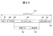
- a data frame 520 using CAN as a communication protocol is shown.
- FIG. 1 is a configuration diagram of a vehicle control system 1000 according to Embodiment 1 of the present invention.
- the vehicle control system 1000 has a configuration in which one or more ECUs that control the vehicle are connected via a network.
- Each ECU controls each part of the vehicle and communicates with other ECUs as necessary.
- the camera ECU 1 recognizes the situation of the outside world using the in-vehicle camera 11 and transmits inter-vehicle distance data to the CAN 5.
- the inter-vehicle distance control ECU 2 receives inter-vehicle distance data, calculates brake force data using this, and transmits it to the CAN 5.
- the pre-crash safe control ECU 3 receives the inter-vehicle distance data, determines the possibility of a collision using the data, and transmits the sudden brake request data to the CAN 5 when the possibility of the collision is high.
- the brake control ECU 4 receives the brake force data and the sudden brake request data, and controls the brake 41 according to them.
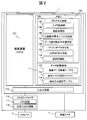
- FIG. 2 is a configuration diagram of the camera ECU 1.
- the camera ECU 1 includes an arithmetic device 101, a memory 102, an input / output circuit 115, and a CAN controller 116.
- the computing device 101 is a processor (Central Processing Unit) that executes each program stored in the memory 102. Equivalent functions can also be configured using hardware such as circuit devices.
- the memory 102 has a program area 103 and a data storage area 111.
- the program area 103 stores a camera control unit 104, a communication processing unit 105, an accurate operation request level determination unit 106, a data error detection method selection unit 107, a parity data addition unit 108, a CRC code addition unit 109, and a communication control unit 110. .
- the functions of these programs will be described later.
- the data storage area 111 stores a communication data management table 112 described later with reference to FIG. 6, a request level determination table 113 described with reference to FIG. 7, and a detection method selection table 114 described with reference to FIG.
- the CAN controller 116 includes a CRC circuit 117 and a signal input / output circuit 118.
- the CRC circuit 117 calculates a CRC code using data to be transmitted to the CAN bus 5, adds the CRC code to the communication packet, and transmits the communication packet to the CAN bus 5. Further, a CRC code is calculated using data received from the CAN bus 5, and a data error is detected by comparing the received CRC code with the calculated CRC code.
- the signal input / output circuit 118 appropriately executes necessary processing such as digital conversion of the communication signal received from the CAN bus 5.
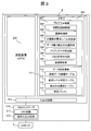
- FIG. 3 is a configuration diagram of the inter-vehicle distance control ECU 2.
- the inter-vehicle distance control ECU 2 includes an arithmetic device 201, a memory 202, an input / output circuit 215, and a CAN controller 216.
- the arithmetic unit 201 is a processor that executes each program stored in the memory 202. Equivalent functions can also be configured using hardware such as circuit devices.
- the memory 202 has a program area 203 and a data storage area 211.
- the program area 203 stores an inter-vehicle distance control unit 204, a communication processing unit 205, an accurate operation request level determination unit 206, a data error detection method selection unit 207, a parity data detection unit 208, a CRC code addition unit 209, and a communication control unit 210. To do. The functions of these programs will be described later.
- the data storage area 211 includes a communication data management table 212 described later with reference to FIG. 9, a request level determination table 213 described with reference to FIG. 10, a detection method selection table 114 described with reference to FIG. 8, and a reception buffer 214 with reference to FIG. Store.
- the configuration of the CAN controller 216 is the same as that of the CAN controller 116 included in the camera ECU 1.
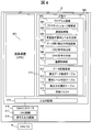
- FIG. 4 is a configuration diagram of the pre-crash safe control ECU 3.
- the pre-crash safe control ECU 3 includes an arithmetic device 301, a memory 302, an input / output circuit 315, and a CAN controller 316.
- the arithmetic unit 301 is a processor that executes each program stored in the memory 302. Equivalent functions can also be configured using hardware such as circuit devices.
- the memory 302 has a program area 303 and a data storage area 311.
- the program area 303 includes a pre-crash safe control unit 304, a communication processing unit 305, an accurate operation request level determination unit 306, a data error detection method selection unit 307, a CRC code detection unit 308, a CRC code addition unit 309, and a communication control unit 310.
- Store. The functions of these programs will be described later.
- the data storage area 311 includes a communication data management table 312 described in FIG. 12, which will be described later, a request level determination table 313 described in FIG. 13, a detection method selection table 114 described in FIG. 8, and a reception buffer 314 described in FIG. Store.
- the configuration of the CAN controller 316 is the same as that of the CAN controller 116 provided in the camera ECU 1.
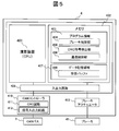
- FIG. 5 is a configuration diagram of the brake control ECU 4.
- the brake control ECU 4 includes a calculation device 401, a memory 402, an input / output circuit 409, a CAN controller 410, and a brake actuator 413 that controls the brake 41.
- the computing device 401 is a processor that executes each program stored in the memory 402. Equivalent functions can also be configured using hardware such as circuit devices.
- the memory 402 has a program area 403 and a data storage area 407.
- the program area 403 stores a brake control unit 404, a CRC code detection unit 405, and a communication control unit 406. The functions of these programs will be described later.
- the data storage area 407 stores a reception buffer 408 described later with reference to FIG.
- the configuration of the CAN controller 410 is the same as that of the CAN controller 116 provided in the camera ECU 1.
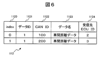
- FIG. 6 is a diagram illustrating an example of the communication data management table 112 provided in the camera ECU 1.
- the communication data management table 112 is a table for managing the type of data transmitted by the camera ECU 1, and includes an index field 1120, a data ID field 1121, a CAN ID field 1122, a data name field 1123, and a receiving ECU ID field 1124.
- the index field 1120 holds a number for identifying each record.
- the data ID field 1121 holds a value that identifies the type of data transmitted by the camera ECU 1.
- the CAN ID field 1122 holds a CAN ID of data transmitted by the camera ECU 1.
- the data name field 1123 holds a data name transmitted by the camera ECU 1.
- the destination ECU ID field 1124 holds the identifier of the ECU that is the data destination.
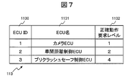
- FIG. 7 is a diagram illustrating an example of the required level determination table 113 provided in the camera ECU 1.
- the request level determination table 113 is a table used to determine how accurately the destination ECU to which the camera ECU 1 transmits control data is required to operate.
- the ECU ID field 1130, the ECU name field 1131, An accurate operation request level field 1132 is included.
- the ECU ID field 1130 holds an identifier for identifying an ECU in the vehicle control system 1000.
- the ECU name field 1131 holds the name of the ECU identified by the ECU ID field 1130.
- the accurate operation request level field 113 holds a value indicating how accurately the ECU identified by the ECU ID field 1130 is requested to operate. The higher the value of this field, the more accurate operation is required.
- ECU operates correctly means that the ECU operates as designed. If the ECU does not operate correctly, the ECU that has a strong degree of influence on safety is required to operate more accurately. Therefore, the value of the accurate operation request level field 1132 is higher.
- FIG. 8 is a diagram showing an example of the detection method selection table 114 provided in the camera ECU 1, the inter-vehicle distance control ECU 2, and the pre-crash safe control ECU 3.
- the detection method selection table 114 is a table used for selecting a data error detection method in accordance with an accurate operation request level required for the reception side ECU, and includes a reception side request level field 1141 and a data error detection method 1142. .
- the reception side request level field 1141 lists the values of the accurate operation request levels required for the reception side ECU.
- the data error detection method 1142 holds a value for designating a data error detection method suitable for the value of the receiving side request level field 1141.
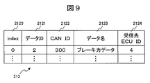
- FIG. 9 is a diagram illustrating an example of the communication data management table 212 provided in the inter-vehicle distance control ECU 2.
- the configuration of the communication data management table 212 is the same as that of the communication data management table 112 provided in the camera ECU 1, but the content of the record to be held corresponds to the control data transmitted by the inter-vehicle distance control ECU 2.
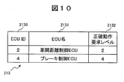
- FIG. 10 is a diagram showing an example of the required level determination table 213 provided in the inter-vehicle distance control ECU 2.
- the structure of the request level determination table 213 is the same as that of the request level determination table 113 provided in the camera ECU 1, but the contents of the record held correspond to the destination to which the inter-vehicle distance control ECU 2 transmits control data.
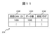
- FIG. 11 shows an example of the reception buffer 214 provided in the inter-vehicle distance control ECU 2.
- the reception buffer 214 is a buffer that temporarily stores data received by the inter-vehicle distance control ECU 2, and includes a reception CAN ID field 2140, a data value field 2141, and a reception flag field 2142.
- the received CAN ID field 2140 holds the CAN ID of the received data.
- the data value field 2141 holds the value of the received data.
- the reception flag field 2142 holds a flag value indicating whether data has been received from the CAN bus 5.
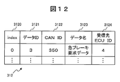
- FIG. 12 is a diagram illustrating an example of the communication data management table 312 provided in the pre-crash safe control ECU 3.
- the configuration of the communication data management table 312 is the same as that of the communication data management table 112 provided in the camera ECU 1, but the contents of the record held correspond to the control data transmitted by the pre-crash safe control ECU 3.
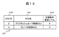
- FIG. 13 is a diagram illustrating an example of a required level determination table 313 provided in the pre-crash safe control ECU 3.
- the configuration of the request level determination table table 313 is the same as that of the request level determination table table 113 provided in the camera ECU 1, but the contents of the record to be held correspond to the destination to which the pre-crash safe control ECU 3 transmits control data. ing.
- FIG. 14 is a diagram illustrating an example of the reception buffer 314 included in the pre-crash safe control ECU 3.
- the configuration of the reception buffer 314 is the same as that of the reception buffer 214 provided in the inter-vehicle distance control ECU 2, but the content of the record to be held corresponds to the data received by the pre-crash safe control ECU 3.
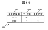
- FIG. 15 is a diagram illustrating an example of the reception buffer 408 provided in the brake control ECU 4.
- the configuration of the reception buffer 408 is the same as that of the reception buffer 214 provided in the inter-vehicle distance control ECU 2, but the content of the record held corresponds to the data received by the brake control ECU 4.
- each device included in the vehicle control system 1000 has been described above.
- the operation flow of each device will be described by taking as an example a process in which the camera ECU 1 calculates the inter-vehicle distance using the in-vehicle camera 11 and transmits inter-vehicle distance data to the CAN 5.
- the camera ECU 1 calculates a detection code using parity data as a data error detection method, and sets it with the inter-vehicle distance data. And send.
- the receiving ECU is the pre-crash safe control ECU 3
- the camera ECU 1 calculates a detection code using CRC as a data error detection method, Send as a set.
- the inter-vehicle distance control ECU 2 calculates a braking force according to the value of the received inter-vehicle distance data, and transmits the braking force data to the brake control ECU 4 using CRC as a data error detection method.
- the pre-crash safe control ECU 3 determines whether or not to issue a sudden brake request according to the value of the received inter-vehicle distance data, and transmits the sudden brake request data to the brake control ECU 4 using CRC as a data error detection method. .
- the brake control ECU 4 controls the brake 41 according to the received brake force data and sudden brake request data.
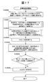
- FIG. 16 is a diagram illustrating an operation flow of the camera control unit 104 included in the camera ECU 1. Hereinafter, each step of FIG. 16 will be described.
- the camera control unit 104 reads out video data captured by the in-vehicle camera 11 and calculates inter-vehicle distance data using the video data.
- the camera control unit 104 calls the communication processing unit 105 using the inter-vehicle distance data and its data ID as arguments, transmits the inter-vehicle distance data, and ends this operation flow. For example, when the data ID of the inter-vehicle distance data is 1, the communication processing unit 105 is called with the inter-vehicle distance data value and the data ID of 1 as arguments. Details of this step will be described with reference to FIG.
- FIG. 17 is a diagram illustrating an operation flow of the communication processing unit 105 provided in the camera ECU 1.
- the communication processing unit 205 and the communication processing unit 305 also perform the same operation flow. Hereinafter, each step of FIG. 17 will be described.
- the communication processing unit 105 sets a variable count that stores the value of the index field 1120 of the communication data management table 112 to 0.
- the communication processing unit 105 sequentially acquires records in the communication data management table 112 while increasing the value of the variable count by one until a data ID field 1121 equal to the received argument is obtained.
- the communication processing unit 105 refers to the record in the communication data management table 112 corresponding to the value of the variable count, and acquires the reception destination ECU ID field 1124.
- the communication processing unit 105 calls the data error detection method selection unit 107 using the acquired accurate operation request level and the data received as an argument to the communication processing unit 105 as an argument, and acquires transmission data with a detection code as a return value.
- the data received as an argument by the communication processing unit 105 is the inter-vehicle distance data.
- the data received as an argument by the communication processing unit 105 is the inter-vehicle distance data.
- the data received as an argument by the communication processing unit 105 is the inter-vehicle distance data.
- a data error detection method selection is performed using the accurate operation request level 4 and the inter-vehicle distance data as arguments. Call unit 107. Details of this step will be described with reference to FIG.
- Step SS105004 The communication processing unit 105 calls the communication control unit (transmission processing) 110 using the CAN ID acquired in step S105003 and the transmission data with detection code acquired in step S105002 as arguments, and transmits the transmission data value with detection code. Details of this step will be described with reference to FIG.
- Step S105005 The communication processing unit 105 determines whether transmission has been performed using all CAN IDs for the same data ID. If the transmission has been completed, the operation flow ends. If the transmission has not been completed, the process advances to step S105006. For example, the communication processing unit 105 determines that the transmission is completed if the count is 1, and the communication processing unit 205 and the communication processing unit 305 determine that the transmission is completed if the count is 0.
- Step S105006 The communication processing unit 105 adds 1 to the count value and returns to step S105001.
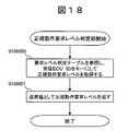
- FIG. 18 is a diagram illustrating an operation flow of the accurate operation request level determination unit 106.
- the accurate operation request level determination unit 206 and the accurate operation request level determination unit 306 perform the same operation flow. Hereinafter, each step of FIG. 18 will be described.
- the correct operation request level determination unit 106 refers to the request level determination table 113 and acquires the correct operation request level field 1132 from a record in which the value of the ECU ID field 1130 matches the received ECU ID as an argument. For example, according to the data example of FIG. 7, when the receiving ECU ID as an argument is 2, 2 is acquired as the accurate operation request level.
- the correct operation request level determination unit 106 returns the correct operation request level field 1132 as a return value, and ends this operation flow.
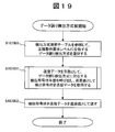
- FIG. 19 is a diagram showing an operation flow of the data error detection method selection unit 107.
- the data error detection method selection unit 207 and the data error detection method selection unit 307 perform the same operation flow. Hereinafter, each step of FIG. 19 will be described.
- the data error detection method selection unit 107 refers to the detection method selection table 114 and records the value of the data error detection method field 1142 from the record in which the value of the reception-side correct operation request level field 1141 is equal to the correct operation request level as an argument To get. For example, according to the data example of FIG. 8, when the correct operation request level is 2, the parity data adding unit is selected as the data error detection method. Note that not all ECUs need to be equipped with all data error detection methods described in the detection method selection table 114. Alternatively, only the data error detection method used by all ECUs may be described in the detection method selection table.
- the data error detection method selection unit 107 calls the detection code providing unit corresponding to the data error detection method selected in step S107000 using the transmission data received as an argument as an argument, and acquires transmission data with a detection code as a return value.
- the data error detection method 1142 selected in step S107000 is a parity data adding unit
- the parity data adding unit 108 is called.
- An operation example when calling the parity data adding unit 108 in this step will be described with reference to FIG. 21, and an operation example when calling the CRC code adding unit 109 will be described with reference to FIG.
- Step S107002 The data error detection method selection unit 107 returns the acquired transmission data with detection code as a return value, and ends this operation flow.
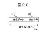
- FIG. 20 is a structural diagram of transmission data 510 with a detection code.
- the transmission data 510 with detection code includes transmission data 511 and a detection code 512.
- the transmission data 511 is data calculated by the camera control unit 104, the inter-vehicle distance control unit 204, or the pre-crash safe control unit 304.
- the maximum size of the transmission data 510 with the detection code is 8 bytes.
- the present invention is not limited to this.
- the maximum size of the transmission data with detection code 510 is 254 bytes.
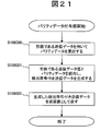
- FIG. 21 is a diagram showing an operation flow of the parity data adding unit 108. Hereinafter, each step of FIG. 21 will be described.
- the parity data adding unit 108 calculates parity data using the transmission data received as an argument.
- the parity data adding unit 108 combines the transmission data as the argument and the parity data calculated in step S108000 to generate transmission data with a detection code.
- Step S108002 The parity data adding unit 108 returns the transmission data with the detection code generated in step S108001 as a return value, and ends this operation flow.
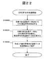
- FIG. 22 is a diagram showing an operation flow of the CRC code assigning unit 109.
- the CRC code assigning unit 209 performs the same operation flow. Hereinafter, each step of FIG. 22 will be described.
- the CRC code assigning unit 109 calculates a CRC detection code using the transmission data received as an argument.
- the CRC code adding unit 109 combines the transmission data as an argument and the CRC detection code calculated in step S109000 to generate transmission data with a detection code.
- Step S109002 The CRC code assigning unit 109 returns the transmission data with the detection code generated in step S109001 as a return value, and ends this operation flow.
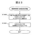
- FIG. 23 is a diagram illustrating an operation flow of the communication control unit (transmission processing) 110.
- the communication control unit (transmission process) 210 and the communication control unit (transmission process) 310 also perform the same operation flow. Hereinafter, each step of FIG. 23 will be described.
- the communication control unit (transmission process) 110 stores the transmission data with the detection code received as an argument in the mailbox of the CAN controller 116.
- the communication control unit (transmission process) 110 sets the transmission request flag of the CAN controller 116 and ends this operation flow.
- the CAN controller 116 transmits the mailbox data corresponding to the set transmission request flag to the CAN bus 5.
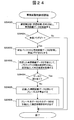
- FIG. 24 is a diagram showing an operation flow of the inter-vehicle distance control unit 204 provided in the inter-vehicle distance control ECU 2. Hereinafter, each step of FIG. 24 will be described.
- the inter-vehicle distance control unit 204 calls the communication control unit (reception process) 210 and receives inter-vehicle distance data. Details of this step will be described with reference to FIG.
- the inter-vehicle distance control unit 204 determines whether or not the reception flag field 2142 of the reception buffer 214 indicating that the inter-vehicle distance data has been received is “1”. When the reception flag field 2142 is 1, the process proceeds to step S204002, and when it is 0, the operation flow ends.
- the inter-vehicle distance control unit 204 acquires inter-vehicle distance data held in the data value field 2141 of the reception buffer 214 and sets the reception flag field 2142 in the same record to 0.
- Step S204003 The inter-vehicle distance control unit 204 calls the parity data detection unit 208 using the inter-vehicle distance data acquired from the reception buffer 214 as an argument, and acquires the determination result as a return value. Details of this step will be described with reference to FIG.
- Step S204004 The inter-vehicle distance control unit 204 determines whether or not the determination result acquired in step S204003 indicates no data error. If there is no data error, the process proceeds to step S204005. If there is a data error, the operation flow ends.
- the inter-vehicle distance control unit 204 calculates the braking force necessary to keep the inter-vehicle distance constant using the received inter-vehicle distance data.
- the inter-vehicle distance control unit 204 uses the calculated braking force data and the value of the data ID field 2121 (2 in the data example of FIG. 9) in the communication data management table 212 corresponding to the braking force data as arguments. 205 is called and this operation
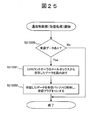
- FIG. 25 is a diagram illustrating an operation flow of the communication control unit (reception process) 210.
- the communication control unit (reception process) 310 and the communication control unit (reception process) 406 also perform the same operation flow. Hereinafter, each step of FIG. 25 will be described.
- Step S210000 The communication control unit (reception process) 210 confirms the reception flag of the CAN controller 216 and determines whether there is reception data. If there is reception data, the process proceeds to step S210001. If there is no reception data, the operation flow is terminated.
- the communication control unit (reception process) 210 reads received data from the mailbox of the CAN controller 216.
- the communication control unit (reception process) 210 searches the reception CAN ID field 2140 of the reception buffer 214 that is equal to the CAN ID of the received data, and stores the reception data in the data value field 2141.
- the communication control unit (reception process) 210 sets the value of the reception flag field 2142 of the record to 1, and ends this operation flow.
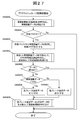
- FIG. 26 is a diagram showing an operation flow of the parity data detection unit 208. Hereinafter, each step of FIG. 26 will be described.
- the parity data detection unit 208 divides the reception data with the detection code received as an argument into parity data and data.
- the data is, for example, inter-vehicle distance data.
- the parity data detection unit 208 calculates parity data using the data acquired in step S208000.
- Step S208002 The parity data detection unit 208 compares the parity data calculated in step S208001 with the parity data received as an argument.
- Step S208003 The parity data detection unit 208 determines whether or not the parity data calculated in step S208001 matches the received parity data received as an argument. If they match, the process proceeds to step S208004, and if they do not match, the process proceeds to step S208005.
- Step S208004 The parity data detection unit 208 returns 0 indicating no data error as a return value, and ends this operation flow.
- Step S208005 The parity data detection unit 208 returns 1 indicating that there is a data error as a return value, and ends the operation flow.
- FIG. 27 is a diagram illustrating an operation flow of the pre-crash safe control unit 304 included in the pre-crash safe ECU 3. Hereinafter, each step of FIG. 27 will be described.
- Step S304000 The pre-crash safe control unit 304 calls the communication control unit (reception process) 310 and receives the inter-vehicle distance data.
- Step S304001 The pre-crash safe control unit 304 determines whether or not the reception flag field 3142 of the reception buffer 314 indicating 1 has received the inter-vehicle distance data. When the reception flag field 3142 is 1, the process proceeds to step S304002, and when it is 0, the operation flow ends.
- Step S304002 The pre-crash safe control unit 304 acquires the inter-vehicle distance data held in the data value field 3141 of the reception buffer 314, and sets the reception flag field 3142 in the same record to 0.
- the pre-crash safe control unit 304 calls the CRC code detection unit 308 using the received inter-vehicle distance data as an argument, and acquires the determination result as a return value.
- Step S304004 The pre-crash safe control unit 304 determines whether or not the determination result acquired in step S304003 indicates no data error. If there is no data error, the process proceeds to step S304005. If there is a data error, the operation flow ends.
- Step S304005 The pre-crash safe control unit 304 determines whether the value of the inter-vehicle distance data acquired in step S304002 is greater than 100. If it is greater than 100, the process proceeds to step S304006, and if it is 100 or less, the process proceeds to step S304007.
- Step S304006 The pre-crash safe control unit 304 sets the sudden brake request data to 1.
- the sudden brake request data is 1, it indicates that the brake control ECU 4 is instructed to perform sudden braking.
- Step S304007 The pre-crash safe control unit 304 sets the sudden brake request data to 0. When the sudden brake request data is 0, it indicates that sudden braking is not performed.
- the pre-crash safe control unit 304 uses the sudden brake request data and the value of the data ID field 3121 (3 in the data example of FIG. 12) of the communication data management table 312 corresponding to the sudden brake request data as arguments. 305 is called to end the operation flow.
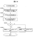
- FIG. 28 is a diagram showing an operation flow of the CRC code detection unit 308.
- the CRC code detection unit 405 also performs the same operation flow. Hereinafter, each step of FIG. 28 will be described.
- the CRC code detection unit 308 divides the reception data with the detection code received as an argument into a CRC code and data.
- the data indicates, for example, inter-vehicle distance data.
- Step S308001 The CRC code detection unit 308 calculates a CRC code using the data acquired in step S308000.
- Step S308002 The CRC code detection unit 308 compares the CRC code calculated in step S308001 with the CRC code received as an argument.
- Step S308003 The CRC code detection unit 308 determines whether or not the CRC code calculated in step S308001 matches the CRC code received as an argument. If they match, the process proceeds to step S308004, and if they do not match, the process proceeds to step S308005.
- Step S308004 The CRC code detection unit 308 returns 0 indicating no data error as a return value, and ends this operation flow.
- Step S308005 The CRC code detection unit 308 returns 1 indicating that there is a data error as a return value, and ends the operation flow.
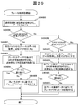
- FIG. 29 is a diagram showing an operation flow of the brake control unit 404. Hereinafter, each step of FIG. 29 will be described.
- Step S404000 The brake control unit 404 calls the communication control unit (reception process) 406 and receives data.
- Step S404001 The brake control unit 404 determines whether or not the reception flag field 4082 of the record in which the reception CAN ID field 4080 of the reception buffer 408 is 300 is “1”. If it is 1, the process proceeds to step S404002. If it is not 1, the process proceeds to step S404006.
- Step S404002 The brake control unit 404 acquires the braking force data held in the data value field 4081 of the reception buffer 408, and sets the reception flag field 4082 of the same record to 0.
- the brake control unit 404 calls the CRC code detection unit 405 using the received brake force data as an argument, and acquires the determination result as a return value.
- Step S404004 The brake control unit 404 determines whether or not the determination result acquired in step S404003 indicates no data error. If there is no data error, the process proceeds to step S404005. If there is a data error, the operation flow ends.
- Step S404005 The brake control unit 404 controls the brake actuator 413 based on the received braking force data, and ends this operation flow.
- Step S404006 The brake control unit 404 determines whether or not the reception flag field 4082 of the record whose reception CAN ID field 4080 of the reception buffer 408 is 350 is “1”. If it is 1, the process proceeds to step S404007. If it is not 1, this operation flow is terminated.
- Step S404007 The brake control unit 404 acquires the sudden brake request data held in the data value field 4081 of the reception buffer 408, and sets the reception flag field 4082 of the same record to 0.
- the brake control unit 404 calls the CRC code detection unit 405 using the received sudden brake request data as an argument, and acquires the determination result as a return value.
- Step S40409 The brake control unit 404 determines whether or not the determination result acquired in step S404008 indicates no data error. If there is no data error, the process proceeds to step S404010. If there is a data error, the operation flow ends.
- Step S404010 The brake control unit 404 controls the brake actuator 413 based on the received sudden brake request data, and ends this operation flow.
- FIG. 30 shows a data frame 520 using CAN as a communication protocol.
- the data frame 520 includes an SOF 521 that indicates the start of the frame, an identifier (ID) 522 that uniquely identifies the frame, a CTRL 523 that indicates the size of the frame, a data field 524 that stores data to be transmitted, and error detection for communication data.
- the transmission data 511 of the transmission data with detection code 510 described in FIG. 20 is transmission data 528, and the detection code 512 is a detection code 529.
- CAN is adopted as a communication protocol
- the camera control unit 104, the inter-vehicle distance control unit 204, the pre-crash safe control unit 304, and the brake control unit 404 execute the above-described processing periodically (for example, at an interval of 10 ms). Configured to do.
- each ECU may perform each process when control data is received from another ECU.
- the network connecting the ECUs is a time trigger network, and in the latter case, an event trigger network.
- the camera ECU 1, the inter-vehicle distance control ECU 2, and the pre-crash safe control ECU 3 select the data error detection method according to the accurate operation request level of the receiving ECU. As a result, the data error detection rate can be guaranteed for each ECU having a different exact operation request level.
- the camera ECU 1, the inter-vehicle distance control ECU 2, and the pre-crash safe control ECU 3 select the data error detection method according to the accurate operation request level of the receiving ECU, so that the data error detection rate is guaranteed.
- the size of the detection code can be kept to a minimum. Thereby, the communication load of the network can be suppressed and the calculation load of the CPU can be suppressed.
- the first embodiment it is possible to detect a data error other than the communication path by adding a detection code to the data field portion of the communication packet. For example, even if the CAN controller 116 adds a CRC code 525 to the entire communication packet and detects a data error on the network, once reaching the ECU, the communication packet is written in the mailbox and the CRC code 525 is not necessary. For this reason, if a data error occurs between the time when the communication packet arrives at the receiving ECU and the time when it is taken out from the mailbox, the error cannot be detected.
- by adding a detection code to the data field it is possible to detect a data error after the communication packet arrives at the receiving ECU.
- the correct operation request level is assigned to each ECU, but the present invention is not limited to this.
- an accurate operation request level may be assigned to each function implemented by each ECU using control data.
- an accurate operation request level may be defined for each function provided in each ECU in the request level determination table 113.
- an accurate operation request level may be assigned to a combination of a function on the data transmitting side and a function on the data receiving side.
- a combination of the transmission side function and the reception side function included in each ECU may be described, and an accurate operation request level may be defined for each combination.
- an accurate operation request level may be assigned to the network bus.
- the request level determination table 113 a combination of a receiving ECU and a network used when transmitting data to the receiving ECU may be described, and an accurate operation request level may be defined for each combination.
- the present invention is not limited to the above-described embodiment, and includes various modifications.
- the above-described embodiment has been described in detail for easy understanding of the present invention, and is not necessarily limited to the one having all the configurations described.
- a part of the configuration of one embodiment can be replaced with the configuration of another embodiment. It is also possible to add the configuration of another embodiment to the configuration of a certain embodiment. Further, with respect to a part of the configuration of each embodiment, another configuration can be added, deleted, or replaced.
- each table does not have to be the one described in each drawing, and it is only necessary to realize the same function. Furthermore, it is not always necessary to implement the table format.
- a table for storing static data such as the request level determination table 113 may be defined when each ECU is manufactured. For example, a value held by each table is received via a network during operation. You may make it preserve
- the above-described configurations, functions, processing units, processing means, etc. may be realized in hardware by designing a part or all of them, for example, with an integrated circuit.
- Each of the above-described configurations, functions, and the like may be realized by software by interpreting and executing a program that realizes each function by the processor.
- Information such as programs, tables, and files for realizing each function can be stored in a recording device such as a memory, a hard disk, an SSD (Solid State Drive), or a recording medium such as an IC card, an SD card, or a DVD.
- SYMBOLS 1 Camera ECU, 11: Car-mounted camera, 101: Arithmetic unit, 102: Memory, 103: Program area, 104: Camera control part, 105: Communication processing part, 106: Accurate operation request level determination part, 107: Data error detection Method selection unit, 108: Parity data adding unit, 109: CRC code adding unit, 110: Communication control unit, 111: Data storage area, 112: Communication data management table, 113: Request level determination table, 114: Detection method selection table 115: input / output circuit, 116: CAN controller, 117: CRC circuit, 118: signal input / output circuit, 2: inter-vehicle distance control ECU, 201: arithmetic unit, 202: memory, 203: program area, 204: inter-vehicle distance control , 205: Communication processing unit, 206: Correct operation request level determination unit, 207: Data Detection method selection unit, 208: parity data detection unit, 209
Landscapes
- Engineering & Computer Science (AREA)
- Computer Networks & Wireless Communication (AREA)
- Signal Processing (AREA)
- Quality & Reliability (AREA)
- Remote Sensing (AREA)
- Radar, Positioning & Navigation (AREA)
- Aviation & Aerospace Engineering (AREA)
- Physics & Mathematics (AREA)
- General Physics & Mathematics (AREA)
- Automation & Control Theory (AREA)
- Small-Scale Networks (AREA)
- Detection And Correction Of Errors (AREA)
- Detection And Prevention Of Errors In Transmission (AREA)
Abstract
Description
図1は、本発明の実施形態1に係る車両制御システム1000の構成図である。車両制御システム1000は、車両を制御する1以上のECUをネットワークで接続した構成を有する。
カメラ制御部104は、車載カメラ11が撮像した映像データを読み出し、これを用いて車間距離データを算出する。
カメラ制御部104は、車間距離データとそのデータIDを引数として通信処理部105を呼び出し、車間距離データを送信し、本動作フローを終了する。例えば、車間距離データのデータIDが1であるとき、車間距離データの値とデータIDの1を引数として通信処理部105を呼び出す。本ステップの詳細は図17で説明する。
通信処理部105は、通信データ管理テーブル112のindexフィールド1120の値を格納する変数countを0にセットする。通信処理部105は、受け取った引数に等しいデータIDフィールド1121が得られるまで、変数countの値を1つずつ増やしながら通信データ管理テーブル112内のレコードを順に取得する。
通信処理部105は、変数countの値に対応する通信データ管理テーブル112内のレコードを参照し、受信先ECU IDフィールド1124を取得する。通信処理部105は、取得した受信ECU IDフィールド1124の値を引数として正確動作要求レベル判定部106を呼び出し、正確動作要求レベルの値を返戻値として取得する。例えば図6で説明したデータ例によれば、count(=index)が0であるとき、受信先ECU IDフィールド1124は2であるので、引数として2を指定して正確動作要求レベル判定部106を呼び出す。本ステップの詳細は図18で説明する。
通信処理部105は、取得した正確動作要求レベルと通信処理部105への引数として受け取ったデータを引数としてデータ誤り検出方式選択部107を呼び出し、返戻値として検出符号付き送信データを取得する。例えば図7で説明したデータ例によれば、通信処理部105が引数として受け取ったデータが車間距離データであり、車間距離制御ECU2へ送信する場合は、正確動作要求レベルの2と車間距離データの値を引数としてデータ誤り検出方式選択部107を呼び出す。同様に、通信処理部105が引数として受け取ったデータが車間距離データであり、プリクラッシュセーフ制御ECU4へ送信するときには、正確動作要求レベルの4と車間距離データの値を引数としてデータ誤り検出方式選択部107を呼び出す。本ステップの詳細は図19で説明する。
通信処理部105は、通信データ管理テーブル112を参照し、countの値に対応するレコードのCAN IDフィールド1122を取得する。例えば図6で説明したデータ例によれば、count(=index)が0であるとき、CAN IDフィールド1122の値として100を取得する。
通信処理部105は、ステップS105003で取得したCAN IDとステップS105002で取得した検出符号付き送信データを引数として通信制御部(送信処理)110を呼び出し、検出符号付き送信データ値を送信する。本ステップの詳細は図23で説明する。
通信処理部105は、同じデータIDに関してすべてのCAN IDを用いて送信済みであるか否かを判定する。送信済みである場合は本動作フローを終了し、送信済みでない場合はステップS105006へ進む。例えば、通信処理部105はcountが1であれば送信完了したと判定し、通信処理部205と通信処理部305はcountが0であれば送信完了したと判定する。
通信処理部105は、countの値に1を加え、ステップS105001へ戻る。
正確動作要求レベル判定部106は、要求レベル判定テーブル113を参照し、ECU IDフィールド1130の値が引数である受信ECU IDと合致するレコードから正確動作要求レベルフィールド1132を取得する。例えば図7のデータ例によれば、引数である受信ECU IDが2である場合は、正確動作要求レベルとして2を取得する。
正確動作要求レベル判定部106は、正確動作要求レベルフィールド1132を返戻値として返し、本動作フローを終了する。
データ誤り検出方式選択部107は、検出方式選択テーブル114を参照して、受信側正確動作要求レベルフィールド1141の値が引数である正確動作要求レベルと等しいレコードから、データ誤り検出方式フィールド1142の値を取得する。例えば図8のデータ例によれば、正確動作要求レベルが2である場合、データ誤り検出方式としてパリティデータ付与部を選択することになる。なお、検出方式選択テーブル114が記述している全てのデータ誤り検出方式を全てのECUが搭載していなくてもよい。あるいは、全てのECUが使用するデータ誤り検出方式のみを検出方式選択テーブル内に記述するようにしてもよい。
データ誤り検出方式選択部107は、引数として受け取った送信データを引数として、ステップS107000で選択したデータ誤り検出方式に対応する検出符号付与部を呼び出し、返戻値として検出符号付き送信データを取得する。例えば、ステップS107000で選択したデータ誤り検出方式1142がパリティデータ付与部である場合は、パリティデータ付与部108を呼び出す。本ステップにおいてパリティデータ付与部108を呼び出す場合の動作例は図21で説明し、CRC符号付与部109を呼び出す場合の動作例は図22で説明する。
データ誤り検出方式選択部107は、取得した検出符号付き送信データを返戻値として返し、本動作フローを終了する。
パリティデータ付与部108は、引数として受け取った送信データを用いて、パリティデータを算出する。
パリティデータ付与部108は、引数である送信データとステップS108000で算出したパリティデータを結合し、検出符号付き送信データを生成する。
パリティデータ付与部108は、ステップS108001で生成した検出符号付き送信データを返戻値として返し、本動作フローを終了する。
CRC符号付与部109は、引数として受け取った送信データを用いて、CRC検出符号を算出する。
CRC符号付与部109は、引数である送信データとステップS109000で算出したCRC検出符号を結合し、検出符号付き送信データを生成する。
CRC符号付与部109は、ステップS109001で生成した検出符号付き送信データを返戻値として返し、本動作フローを終了する。
通信制御部(送信処理)110は、引数として受け取った検出符号付き送信データをCANコントローラ116のメールボックスに格納する。
通信制御部(送信処理)110は、CANコントローラ116の送信要求フラグをセットし、本動作フローを終了する。CANコントローラ116は、セットされた送信要求フラグに対応するメールボックスのデータをCANバス5に送信する。
車間距離制御部204は、通信制御部(受信処理)210を呼び出し、車間距離データを受信する。本ステップの詳細は図25で説明する。
車間距離制御部204は、車間距離データを受信したことを示す、受信バッファ214の受信フラグフィールド2142が、1であるか否かを判定する。受信フラグフィールド2142が1であるときはステップS204002へ進み、0であるときは本動作フローを終了する。
車間距離制御部204は、受信バッファ214のデータ値フィールド2141が保持している車間距離データを取得し、同じレコード内の受信フラグフィールド2142を0にする。
車間距離制御部204は、受信バッファ214から取得した車間距離データを引数として、パリティデータ検出部208を呼び出し、返戻値として判定結果を取得する。本ステップの詳細は図26で説明する。
車間距離制御部204は、ステップS204003で取得した判定結果がデータ誤りなしを示しているか否かを判定する。データ誤りがない場合はステップS204005へ進み、データ誤りがある場合は本動作フローを終了する。
車間距離制御部204は、受信した車間距離データを用いて、車間距離を一定に保つために必要なブレーキ力を算出する。
車間距離制御部204は、算出したブレーキ力データと、ブレーキ力データに対応する通信データ管理テーブル212内のデータIDフィールド2121の値(図9のデータ例では2)とを引数として、通信処理部205を呼び出し、本動作フローを終了する。
通信制御部(受信処理)210は、CANコントローラ216の受信フラグを確認し、受信データがあるか否かを判定する。受信データがある場合はステップS210001へ進み、受信データがない場合は本動作フローを終了する。
通信制御部(受信処理)210は、CANコントローラ216のメールボックスから受信データを読み出す。
通信制御部(受信処理)210は、受信したデータのCAN IDと等しい受信バッファ214の受信CAN IDフィールド2140を検索し、受信データをデータ値フィールド2141に格納する。通信制御部(受信処理)210は、同レコードの受信フラグフィールド2142の値を1にセットし、本動作フローを終了する。
パリティデータ検出部208は、引数として受け取った検出符号付き受信データを、パリティデータとデータに分割する。データとは、例えば車間距離データである。
パリティデータ検出部208は、ステップS208000で取得したデータを用いてパリティデータを算出する。
パリティデータ検出部208は、ステップS208001で算出したパリティデータと引数として受け取ったパリティデータを比較する。
パリティデータ検出部208は、ステップS208001で算出したパリティデータと引数として受け取った受信したパリティデータが一致するか否かを判定する。一致する場合はステップS208004に進み、一致しない場合はステップS208005へ進む。
パリティデータ検出部208は、返戻値としてデータ誤りなしを示す0を返し、本動作フローを終了する。
パリティデータ検出部208は、返戻値としてデータ誤りありを示す1を返し、動作フローを終了する。
プリクラッシュセーフ制御部304は、通信制御部(受信処理)310を呼び出し、車間距離データを受信する。
プリクラッシュセーフ制御部304は、車間距離データを受信したことを示す、受信バッファ314の受信フラグフィールド3142が、1であるかを判定する。受信フラグフィールド3142が1であるときはステップS304002へ進み、0であるときは本動作フローを終了する。
プリクラッシュセーフ制御部304は、受信バッファ314のデータ値フィールド3141が保持している車間距離データを取得し、同じレコード内の受信フラグフィールド3142を0にする。
プリクラッシュセーフ制御部304は、受信した車間距離データを引数として、CRC符号検出部308を呼び出し、返戻値として判定結果を取得する。
プリクラッシュセーフ制御部304は、ステップS304003で取得した判定結果がデータ誤りなしを示しているか否かを判定する。データ誤りがない場合はステップS304005へ進み、データ誤りがある場合は本動作フローを終了する。
プリクラッシュセーフ制御部304は、ステップS304002で取得した車間距離データの値が100より大きいか否かを判定する。100より大きい場合はステップS304006へ進み、100以下である場合はステップS304007に進む。
プリクラッシュセーフ制御部304は、急ブレーキ要求データを1にセットする。急ブレーキ要求データが1である場合は、急ブレーキを実施するようブレーキ制御ECU4に指示することを示す。
プリクラッシュセーフ制御部304は、急ブレーキ要求データを0にセットする。急ブレーキ要求データが0である場合は、急ブレーキを実施しないことを示す。
プリクラッシュセーフ制御部304は、急ブレーキ要求データと、急ブレーキ要求データに対応する通信データ管理テーブル312のデータIDフィールド3121の値(図12のデータ例では3)とを引数として、通信処理部305を呼び出し、本動作フローを終了する。
CRC符号検出部308は、引数として受け取った検出符号付き受信データを、CRC符号とデータに分割する。データとは、例えば車間距離データを示す。
CRC符号検出部308は、ステップS308000で取得したデータを用いてCRC符号を算出する。
CRC符号検出部308は、ステップS308001で算出したCRC符号と引数として受け取ったCRC符号を比較する。
CRC符号検出部308は、ステップS308001で算出したCRC符号と引数として受け取ったCRC符号が一致するか否かを判定する。一致する場合はステップS308004へ進み、一致しない場合はステップS308005へ進む。
CRC符号検出部308は、返戻値としてデータ誤りなしを示す0を返し、本動作フローを終了する。
CRC符号検出部308は、返戻値としてデータ誤りありを示す1を返し、動作フローを終了する。
ブレーキ制御部404は、通信制御部(受信処理)406を呼び出し、データを受信する。
ブレーキ制御部404は、受信バッファ408の受信CAN IDフィールド4080が300であるレコードの受信フラグフィールド4082が1であるか否かを判定する。1である場合はステップS404002に進み、1でない場合はステップS404006に進む。
ブレーキ制御部404は、受信バッファ408のデータ値フィールド4081が保持しているブレーキ力データを取得し、同じレコードの受信フラグフィールド4082を0にする。
ブレーキ制御部404は、受信したブレーキ力データを引数として、CRC符号検出部405を呼び出し、返戻値として判定結果を取得する。
ブレーキ制御部404は、ステップS404003で取得した判定結果がデータ誤りなしを示しているか否かを判定する。データ誤りがない場合はステップS404005へ進み、データ誤りがある場合は本動作フローを終了する。
ブレーキ制御部404は、受信したブレーキ力データに基づいてブレーキアクチュエータ413を制御し、本動作フローを終了する。
ブレーキ制御部404は、受信バッファ408の受信CAN IDフィールド4080が350であるレコードの受信フラグフィールド4082が1であるか否かを判定する。1である場合はステップS404007に進み、1でない場合は本動作フローを終了する。
ブレーキ制御部404は、受信バッファ408のデータ値フィールド4081が保持している急ブレーキ要求データを取得し、同じレコードの受信フラグフィールド4082を0にする。
ブレーキ制御部404は、受信した急ブレーキ要求データを引数として、CRC符号検出部405を呼び出し、返戻値として判定結果を取得する。
ブレーキ制御部404は、ステップS404008で取得した判定結果がデータ誤りなしを示しているか否かを判定する。データ誤りがない場合はステップS404010へ進み、データ誤りがある場合は本動作フローを終了する。
ブレーキ制御部404は、受信した急ブレーキ要求データに基づいてブレーキアクチュエータ413を制御し、本動作フローを終了する。
以上のように、本実施形態1によれば、カメラECU1、車間距離制御ECU2、プリクラッシュセーフ制御ECU3は、受信ECUの正確動作要求レベルに応じてデータ誤り検出方式を選択する。これにより、正確動作要求レベルが異なるECUごとにデータ誤り検出率を保証することができる。
実施形態1では、正確動作要求レベルをECU単位で割り当てているが、これに限らない。例えば、各ECUが制御データを用いて実施する機能毎に正確動作要求レベルを割り当ててもよい。この場合は、要求レベル判定テーブル113において、各ECUが備える機能毎に正確動作要求レベルを定義するようにすればよい。
実施形態1~2において、要求レベル判定テーブル113などを用いずに、受信ECUの正確動作要求レベルを判定することができる場合は、その手法を用いてもよい。例えばデータ種別毎に正確動作要求レベルが定まっているような場合は、データIDやCAN IDを用いて、受信ECUの正確動作要求レベルを判定することができる。
Claims (11)
- ネットワークを介して制御データを送受信する通信部と、
前記送信部が送信する制御データに誤り検出符号を付与する検出符号付与部と、
前記制御データを受信する受信装置がどの程度正確に動作することを要求されているかを示す正確動作要求レベルを判定する正確動作要求レベル判定部と、
を備え、
前記検出符号付与部は、
前記正確動作要求レベル判定部が判定した前記正確動作要求レベルに応じて、前記誤り検出符号の誤り検出能力を変更する
ことを特徴とする車両制御装置。 - 前記検出符号付与部は、
前記通信部が送信する通信パケットのうち前記制御データを記述した部分に、前記誤り検出符号を付与する
ことを特徴とする請求項1記載の車両制御装置。 - 前記通信部は、
前記検出符号付与部が前記誤り検出符号を付与した前記制御データを格納した通信パケットに、前記検出符号付与部が付与する前記誤り検出符号とは別の誤り検出符号を付与する
ことを特徴とする請求項2記載の車両制御装置。 - 前記受信装置と前記正確動作要求レベルの対応関係を記述した正確動作要求レベルテーブルを備え、
前記正確動作要求レベル判定部は、
前記正確動作要求レベルテーブルの記述にしたがって、前記受信装置の前記正確動作要求レベルを判定する
ことを特徴とする請求項1記載の車両制御装置。 - 前記正確動作要求レベル判定部は、
前記受信装置が前記制御データを用いて実行する機能毎に、前記正確動作要求レベルを判定する
ことを特徴とする請求項1記載の車両制御装置。 - 前記正確動作要求レベル判定部は、
前記受信装置が前記制御データを用いて実行する機能と、前記車両制御装置が備える機能との組合せ毎に、前記正確動作要求レベルを判定する
ことを特徴とする請求項1記載の車両制御装置。 - 前記正確動作要求レベル判定部は、
前記ネットワークと前記受信装置の組合せ毎に、前記正確動作要求レベルを判定する
ことを特徴とする請求項1記載の車両制御装置。 - 前記制御データを受信する受信装置と、前記制御データの種別との対応関係を記述した通信データ管理テーブルを備え、
前記正確動作要求レベル判定部は、前記通信データ管理テーブルの記述にしたがって前記制御データを受信する受信装置を特定し、その受信装置が要求されている前記正確動作要求レベルを判定する
ことを特徴とする請求項1記載の車両制御装置。 - 請求項1記載の車両制御装置を複数有し、
複数の前記車両制御装置が前記ネットワークを介して接続されている
ことを特徴とする車両制御システム。 - 前記ネットワークはイベントトリガネットワークである
ことを特徴とする請求項9記載の車両制御システム。 - 前記ネットワークはタイムトリガネットワークである
ことを特徴とする請求項9記載の車両制御システム。
Priority Applications (2)
| Application Number | Priority Date | Filing Date | Title |
|---|---|---|---|
| US14/124,149 US20140107863A1 (en) | 2011-06-09 | 2012-06-04 | Vehicle Control Device, Vehicle Control System |
| DE112012002408.7T DE112012002408T5 (de) | 2011-06-09 | 2012-06-04 | Fahrzeug-Steuervorrichtung, Fahrzeug-Steuersystem |
Applications Claiming Priority (2)
| Application Number | Priority Date | Filing Date | Title |
|---|---|---|---|
| JP2011129535A JP2012257122A (ja) | 2011-06-09 | 2011-06-09 | 車両制御装置、車両制御システム |
| JP2011-129535 | 2011-06-09 |
Publications (1)
| Publication Number | Publication Date |
|---|---|
| WO2012169456A1 true WO2012169456A1 (ja) | 2012-12-13 |
Family
ID=47296019
Family Applications (1)
| Application Number | Title | Priority Date | Filing Date |
|---|---|---|---|
| PCT/JP2012/064360 Ceased WO2012169456A1 (ja) | 2011-06-09 | 2012-06-04 | 車両制御装置、車両制御システム |
Country Status (4)
| Country | Link |
|---|---|
| US (1) | US20140107863A1 (ja) |
| JP (1) | JP2012257122A (ja) |
| DE (1) | DE112012002408T5 (ja) |
| WO (1) | WO2012169456A1 (ja) |
Families Citing this family (7)
| Publication number | Priority date | Publication date | Assignee | Title |
|---|---|---|---|---|
| KR101519777B1 (ko) * | 2014-01-29 | 2015-05-12 | 현대자동차주식회사 | 차량 네트워크 내의 제어기간의 데이터 송신 방법 및 수신 방법 |
| JP2019502297A (ja) * | 2015-11-13 | 2019-01-24 | サンデル・アビオニクス・インコーポレイテッド | アビオニクスシステム、アーキテクチャ、および方法 |
| US11277558B2 (en) * | 2016-02-01 | 2022-03-15 | Magna Electronics Inc. | Vehicle vision system with master-slave camera configuration |
| CN107181725A (zh) * | 2016-03-11 | 2017-09-19 | 比亚迪股份有限公司 | 车辆安全通信方法、装置、车辆多媒体系统及车辆 |
| CN107181722A (zh) * | 2016-03-11 | 2017-09-19 | 比亚迪股份有限公司 | 车辆安全通信方法、装置、车辆多媒体系统及车辆 |
| DE102018218257A1 (de) * | 2018-10-25 | 2020-04-30 | Robert Bosch Gmbh | Steuergerät |
| US20200361452A1 (en) * | 2019-05-13 | 2020-11-19 | Toyota Research Institute, Inc. | Vehicles and methods for performing tasks based on confidence in accuracy of module output |
Citations (7)
| Publication number | Priority date | Publication date | Assignee | Title |
|---|---|---|---|---|
| JPS63237628A (ja) * | 1987-03-26 | 1988-10-04 | Furukawa Electric Co Ltd:The | 車両用多重伝送システムにおける符号化方法 |
| JPH11177590A (ja) * | 1997-12-12 | 1999-07-02 | Denso Corp | 多重通信システム |
| JP2001265402A (ja) * | 2000-03-22 | 2001-09-28 | Hitachi Ltd | 車両用制御装置 |
| JP2004193664A (ja) * | 2002-12-06 | 2004-07-08 | Fanuc Ltd | エラー検出/訂正方式及び該方式を用いた制御装置 |
| JP2007043680A (ja) * | 2005-06-30 | 2007-02-15 | Hitachi Ltd | 送信装置,受信装置及び通信システム |
| JP2010098626A (ja) * | 2008-10-20 | 2010-04-30 | Hitachi Automotive Systems Ltd | 車載ゲートウェイ装置におけるルーティング方法 |
| JP2010178098A (ja) * | 2009-01-30 | 2010-08-12 | Hitachi Automotive Systems Ltd | 車両制御ネットワーク中継装置 |
Family Cites Families (22)
| Publication number | Priority date | Publication date | Assignee | Title |
|---|---|---|---|---|
| JPH11175331A (ja) * | 1997-12-15 | 1999-07-02 | Denso Corp | 車両用lanシステムにおけるromの書換方法及び車載制御装置 |
| US6654648B2 (en) * | 2000-04-03 | 2003-11-25 | Toyota Jidosha Kabushiki Kaisha | Technique of monitoring abnormality in plurality of CPUs or controllers |
| DE10248456A1 (de) * | 2001-10-19 | 2003-06-18 | Denso Corp | Fahrzeugkommunikationssystem |
| JP4281109B2 (ja) * | 2003-12-11 | 2009-06-17 | 株式会社デンソー | 車両用補機診断システム |
| JP4789420B2 (ja) * | 2004-03-04 | 2011-10-12 | トヨタ自動車株式会社 | 車両制御システムにおけるデータ処理装置 |
| EP1882613A4 (en) * | 2005-05-11 | 2010-01-06 | Hitachi Ltd | VEHICLE AND VEHICLE COMMUNICATION CONTROL DEVICE |
| JP2007038904A (ja) * | 2005-08-04 | 2007-02-15 | Fujitsu Ten Ltd | 車載ゲートウェイ装置及び同装置におけるメッセージ中継方法 |
| JP4682916B2 (ja) * | 2005-10-11 | 2011-05-11 | 株式会社デンソー | 通信システム及び通信装置 |
| JP4734089B2 (ja) * | 2005-10-27 | 2011-07-27 | 日立オートモティブシステムズ株式会社 | 車載端末 |
| US20080298256A1 (en) * | 2007-05-30 | 2008-12-04 | Hitachi, Ltd. | Distributed System |
| JP4512621B2 (ja) * | 2007-08-06 | 2010-07-28 | 株式会社日立製作所 | 分散システム |
| JP2009166550A (ja) * | 2008-01-11 | 2009-07-30 | Mitsubishi Electric Corp | 車載機器遠隔制御システムおよび車載機器遠隔制御方法 |
| JP5046345B2 (ja) * | 2008-05-29 | 2012-10-10 | 株式会社オートネットワーク技術研究所 | 通信装置、及び通信システム |
| JP5608409B2 (ja) * | 2010-04-23 | 2014-10-15 | ルネサスエレクトロニクス株式会社 | 自己診断システム及び検査回路判定方法 |
| JP5510275B2 (ja) * | 2010-11-08 | 2014-06-04 | 株式会社デンソー | 通信システム、マスタノード、スレーブノード |
| JP5353867B2 (ja) * | 2010-12-02 | 2013-11-27 | 株式会社デンソー | 回転機の制御装置 |
| JP5541234B2 (ja) * | 2011-06-08 | 2014-07-09 | 株式会社デンソー | トランシーバ |
| JP2013062722A (ja) * | 2011-09-14 | 2013-04-04 | Denso Corp | 通信システム及び、当該通信システムを構成するスレーブノード |
| KR101582062B1 (ko) * | 2011-12-02 | 2015-12-31 | 가부시키가이샤 오토네트웍스 테크놀로지스 | 송신 메시지 생성 장치 및 차재 통신 시스템 |
| JP2014058210A (ja) * | 2012-09-18 | 2014-04-03 | Hitachi Automotive Systems Ltd | 車両制御装置および車両制御システム |
| JP5721754B2 (ja) * | 2013-01-28 | 2015-05-20 | オムロンオートモーティブエレクトロニクス株式会社 | 通信システム及び通信装置 |
| US9178908B2 (en) * | 2013-03-15 | 2015-11-03 | Shape Security, Inc. | Protecting against the introduction of alien content |
-
2011
- 2011-06-09 JP JP2011129535A patent/JP2012257122A/ja active Pending
-
2012
- 2012-06-04 US US14/124,149 patent/US20140107863A1/en not_active Abandoned
- 2012-06-04 WO PCT/JP2012/064360 patent/WO2012169456A1/ja not_active Ceased
- 2012-06-04 DE DE112012002408.7T patent/DE112012002408T5/de not_active Withdrawn
Patent Citations (7)
| Publication number | Priority date | Publication date | Assignee | Title |
|---|---|---|---|---|
| JPS63237628A (ja) * | 1987-03-26 | 1988-10-04 | Furukawa Electric Co Ltd:The | 車両用多重伝送システムにおける符号化方法 |
| JPH11177590A (ja) * | 1997-12-12 | 1999-07-02 | Denso Corp | 多重通信システム |
| JP2001265402A (ja) * | 2000-03-22 | 2001-09-28 | Hitachi Ltd | 車両用制御装置 |
| JP2004193664A (ja) * | 2002-12-06 | 2004-07-08 | Fanuc Ltd | エラー検出/訂正方式及び該方式を用いた制御装置 |
| JP2007043680A (ja) * | 2005-06-30 | 2007-02-15 | Hitachi Ltd | 送信装置,受信装置及び通信システム |
| JP2010098626A (ja) * | 2008-10-20 | 2010-04-30 | Hitachi Automotive Systems Ltd | 車載ゲートウェイ装置におけるルーティング方法 |
| JP2010178098A (ja) * | 2009-01-30 | 2010-08-12 | Hitachi Automotive Systems Ltd | 車両制御ネットワーク中継装置 |
Also Published As
| Publication number | Publication date |
|---|---|
| US20140107863A1 (en) | 2014-04-17 |
| DE112012002408T5 (de) | 2014-04-30 |
| JP2012257122A (ja) | 2012-12-27 |
Similar Documents
| Publication | Publication Date | Title |
|---|---|---|
| JP2012257122A (ja) | 車両制御装置、車両制御システム | |
| US11843477B2 (en) | Anomaly determination method, anomaly determination device, and recording medium | |
| EP4092970A1 (en) | Monitoring controller area network (can) xl nodes | |
| US9323596B2 (en) | Network apparatus and method of monitoring processor | |
| CN115378756B (zh) | 监控控制器域网络(can)xl节点 | |
| CN107306185B (zh) | 用于避免对数据传输的操纵的方法和装置 | |
| CN112347021A (zh) | 用于串行通信装置的安全模块 | |
| CN113626235A (zh) | 容错处理的方法、装置和服务器 | |
| JP2008225558A (ja) | データ中継集積回路、データ中継装置およびデータ中継方法 | |
| CN101604270B (zh) | 基于vxworks操作系统的ARINC429通信冗余方法 | |
| CN102884744B (zh) | 用于保护有待于通过接口传输的数据包的方法和设备 | |
| JP7638186B2 (ja) | 管理装置、通信制御システム、及び通信制御方法 | |
| US8108736B2 (en) | Multi-partition computer system, failure handling method and program therefor | |
| US20160147702A1 (en) | Communication control device, method of communicating a frame, and storage medium | |
| JP2010165105A (ja) | 通信装置及びその制御プログラム | |
| CN107066347A (zh) | 用于生成输出数据流的方法和设备 | |
| JP7005201B2 (ja) | 通信メッセージ変換装置 | |
| CN120455415A (zh) | 数据重传方法、数据传输系统以及网络装置 | |
| US9319314B2 (en) | Apparatus and method for using link-tail of link list to store data pattern which is indicative of end of link list and auxiliary information | |
| KR102474800B1 (ko) | 게이트웨이 및 게이트웨이 제어방법 | |
| US12549488B2 (en) | Selective and diverse traffic replication | |
| JP2006253922A (ja) | ゲートウェイ装置及びゲートウェイ装置におけるデータ転送方法 | |
| WO2007099584A1 (ja) | エラー検出装置 | |
| JP2019201289A (ja) | 電子制御装置 | |
| US20250265108A1 (en) | Communication device and communication method |
Legal Events
| Date | Code | Title | Description |
|---|---|---|---|
| 121 | Ep: the epo has been informed by wipo that ep was designated in this application |
Ref document number: 12797153 Country of ref document: EP Kind code of ref document: A1 |
|
| WWE | Wipo information: entry into national phase |
Ref document number: 14124149 Country of ref document: US |
|
| WWE | Wipo information: entry into national phase |
Ref document number: 112012002408 Country of ref document: DE Ref document number: 1120120024087 Country of ref document: DE |
|
| 122 | Ep: pct application non-entry in european phase |
Ref document number: 12797153 Country of ref document: EP Kind code of ref document: A1 |