WO2012169068A1 - 携帯型電子機器、および、防水カバー - Google Patents
携帯型電子機器、および、防水カバー Download PDFInfo
- Publication number
- WO2012169068A1 WO2012169068A1 PCT/JP2011/063378 JP2011063378W WO2012169068A1 WO 2012169068 A1 WO2012169068 A1 WO 2012169068A1 JP 2011063378 W JP2011063378 W JP 2011063378W WO 2012169068 A1 WO2012169068 A1 WO 2012169068A1
- Authority
- WO
- WIPO (PCT)
- Prior art keywords
- electronic device
- portable electronic
- defining
- sealing member
- lid
- Prior art date
- Legal status (The legal status is an assumption and is not a legal conclusion. Google has not performed a legal analysis and makes no representation as to the accuracy of the status listed.)
- Ceased
Links
Images








Classifications
-
- H—ELECTRICITY
- H04—ELECTRIC COMMUNICATION TECHNIQUE
- H04M—TELEPHONIC COMMUNICATION
- H04M1/00—Substation equipment, e.g. for use by subscribers
- H04M1/02—Constructional features of telephone sets
- H04M1/0202—Portable telephone sets, e.g. cordless phones, mobile phones or bar type handsets
-
- H—ELECTRICITY
- H01—ELECTRIC ELEMENTS
- H01M—PROCESSES OR MEANS, e.g. BATTERIES, FOR THE DIRECT CONVERSION OF CHEMICAL ENERGY INTO ELECTRICAL ENERGY
- H01M50/00—Constructional details or processes of manufacture of the non-active parts of electrochemical cells other than fuel cells, e.g. hybrid cells
- H01M50/20—Mountings; Secondary casings or frames; Racks, modules or packs; Suspension devices; Shock absorbers; Transport or carrying devices; Holders
-
- H—ELECTRICITY
- H04—ELECTRIC COMMUNICATION TECHNIQUE
- H04B—TRANSMISSION
- H04B1/00—Details of transmission systems, not covered by a single one of groups H04B3/00 - H04B13/00; Details of transmission systems not characterised by the medium used for transmission
- H04B1/38—Transceivers, i.e. devices in which transmitter and receiver form a structural unit and in which at least one part is used for functions of transmitting and receiving
- H04B1/3827—Portable transceivers
- H04B1/3888—Arrangements for carrying or protecting transceivers
-
- H—ELECTRICITY
- H04—ELECTRIC COMMUNICATION TECHNIQUE
- H04M—TELEPHONIC COMMUNICATION
- H04M1/00—Substation equipment, e.g. for use by subscribers
- H04M1/02—Constructional features of telephone sets
-
- H—ELECTRICITY
- H04—ELECTRIC COMMUNICATION TECHNIQUE
- H04M—TELEPHONIC COMMUNICATION
- H04M1/00—Substation equipment, e.g. for use by subscribers
- H04M1/02—Constructional features of telephone sets
- H04M1/0202—Portable telephone sets, e.g. cordless phones, mobile phones or bar type handsets
- H04M1/0206—Portable telephones comprising a plurality of mechanically joined movable body parts, e.g. hinged housings
- H04M1/0208—Portable telephones comprising a plurality of mechanically joined movable body parts, e.g. hinged housings characterized by the relative motions of the body parts
- H04M1/0214—Foldable telephones, i.e. with body parts pivoting to an open position around an axis parallel to the plane they define in closed position
-
- H—ELECTRICITY
- H04—ELECTRIC COMMUNICATION TECHNIQUE
- H04M—TELEPHONIC COMMUNICATION
- H04M1/00—Substation equipment, e.g. for use by subscribers
- H04M1/02—Constructional features of telephone sets
- H04M1/0202—Portable telephone sets, e.g. cordless phones, mobile phones or bar type handsets
- H04M1/026—Details of the structure or mounting of specific components
- H04M1/0262—Details of the structure or mounting of specific components for a battery compartment
-
- H—ELECTRICITY
- H04—ELECTRIC COMMUNICATION TECHNIQUE
- H04M—TELEPHONIC COMMUNICATION
- H04M1/00—Substation equipment, e.g. for use by subscribers
- H04M1/02—Constructional features of telephone sets
- H04M1/0202—Portable telephone sets, e.g. cordless phones, mobile phones or bar type handsets
- H04M1/026—Details of the structure or mounting of specific components
- H04M1/0274—Details of the structure or mounting of specific components for an electrical connector module
-
- H—ELECTRICITY
- H04—ELECTRIC COMMUNICATION TECHNIQUE
- H04M—TELEPHONIC COMMUNICATION
- H04M1/00—Substation equipment, e.g. for use by subscribers
- H04M1/02—Constructional features of telephone sets
- H04M1/18—Telephone sets specially adapted for use in ships, mines, or other places exposed to adverse environment
-
- Y—GENERAL TAGGING OF NEW TECHNOLOGICAL DEVELOPMENTS; GENERAL TAGGING OF CROSS-SECTIONAL TECHNOLOGIES SPANNING OVER SEVERAL SECTIONS OF THE IPC; TECHNICAL SUBJECTS COVERED BY FORMER USPC CROSS-REFERENCE ART COLLECTIONS [XRACs] AND DIGESTS
- Y02—TECHNOLOGIES OR APPLICATIONS FOR MITIGATION OR ADAPTATION AGAINST CLIMATE CHANGE
- Y02E—REDUCTION OF GREENHOUSE GAS [GHG] EMISSIONS, RELATED TO ENERGY GENERATION, TRANSMISSION OR DISTRIBUTION
- Y02E60/00—Enabling technologies; Technologies with a potential or indirect contribution to GHG emissions mitigation
- Y02E60/10—Energy storage using batteries
Definitions
- the embodiments discussed herein relate to a portable electronic device and a waterproof cover used in the portable electronic device.
- a sealing member that seals a waterproof region is used in a portable electronic device such as a cellular phone.
- a water-proof packing that is crushed from both sides in the width direction of a portable electronic device is known.
- a deformation preventing rib for preventing deformation of the water stop packing is known.
- the waterproof cover having the waterproof gasket that is crushed from both sides in the width direction of the portable electronic device as described above requires a wall thickness that can withstand the pressing of the waterproof gasket, and the dimension in the width direction is large. Become.
- such a waterproof cover also requires a space for securing the bending R at the four corners of the waterproof packing.
- the waterproof area is, for example, a battery housing portion
- the size of the electronic device is increased, for example, in the width direction due to the recent increase in battery capacity, and the size of the electronic device is maintained for ease of handling the electronic device. It is difficult to achieve both.
- the space where the water stop packing is disposed is also limited. For this reason, if the misalignment occurs in the water-stopping packing, the water-stopping performance cannot be ensured.
- the portable electronic device and the waterproof cover disclosed in this specification can reduce the size of the portable electronic device and ensure water stopping performance.
- the portable electronic device disclosed in the present specification includes a main body having a waterproof region and a lid that covers the waterproof region.
- One of the lid and the main body is in contact with the contact surface formed on the other same surface over the entire circumference of the waterproof region to seal the waterproof region A member and a defining part that defines the position of the sealing member.
- the waterproof cover disclosed in this specification is a lid that covers the waterproof region of the main body of the portable electronic device.
- the waterproof cover is in contact with the contact surface formed on the same surface around the waterproof region of the main body part over the entire circumference of the waterproof region, and seals the waterproof region.
- the portable electronic device and the waterproof cover disclosed in this specification it is possible to reduce the size of the portable electronic device and to ensure water stopping performance.
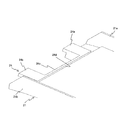
- FIG. 1 It is a disassembled perspective view which shows a mobile telephone. It is the perspective view which looked at the cover part from the inside. It is a perspective view which shows a rectangular resin sheet. It is a perspective view which shows a frame-shaped resin sheet. It is a perspective view which shows the cover part of the state which removed the resin sheet. It is a perspective view (the 1) which shows the modification of a wall surface integrated type prescription
- FIG. 14 is a sectional view taken along line BB in FIG. It is CC sectional drawing of FIG. It is the D section enlarged view of FIG.
- FIG. 14 is a perspective view which shows the cover part whose left wall surface is a prescription
- It is a perspective view which shows the prescription
- It is a perspective view which shows the prescription
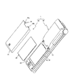
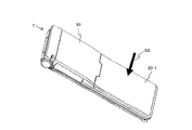
- FIG. 1 is an exploded perspective view showing the mobile phone 1.
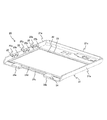
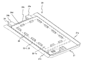
- FIG. 2 is a perspective view of the lid 20 as viewed from the inside.
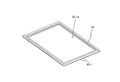
- FIG. 3 is a perspective view showing a rectangular resin sheet 22.
- a mobile phone 1 shown in FIG. 1 includes a main body 10 and a lid 20 that is a waterproof cover.
- the mobile phone 1 is an example of a portable electronic device.
- the lid part 20 is arranged so as to cover the battery storage part 11 of the main body part 10.
- a battery 30 is disposed in the battery storage unit 11.
- the battery storage unit 11 is an example of a waterproof region.
- a flat portion 12 is formed around the battery storage portion 11 in the main body portion 10.
- the flat portion 12 is formed on the same plane and continuously in the circumferential direction of the battery storage portion 11.
- the flat surface portion 12 is an example of a contact surface that is formed on the same surface and contacts the sealing member 23 of the lid portion 20.
- the lid member 20 When the lid member 20 is attached to the mobile phone 1 by sliding while the sealing member 23 is in contact with and pressed against the flat surface portion 12, the flat surface portion 12 is sealed even if the sealing member 23 slides. It is formed in a size that can maintain contact with the stop member 23.
- the lid portion 20 includes a cover body 21, a resin sheet 22, a sealing member 23, a claw portion integrated defining portion 24, and a wall surface integrated defining portion 25. .
- the cover main body 21 has a substantially rectangular shape with the same width as the main body 10 of the mobile phone 1, and forms the bottom surface of the back surface of the main body 10 (the back surface of the mobile phone 1). As shown in FIG. 2, a left wall surface 21 a, a right wall surface 21 b, and a bottom wall surface 21 c are erected around the cover body 21. The left wall surface 21a, the right wall surface 21b, and the bottom wall surface 21c form part of the left and right side surfaces and part of the bottom surface of the main body unit 10.
- the resin sheet 22 has a rectangular thin plate shape, and is joined to the inside of the cover body 21 through, for example, a double-sided tape.
- the resin sheet 22 is made of, for example, polyethylene terephthalate, polycarbonate, or polyimide, and has flexibility.
- a sealing member 23 is provided on the peripheral edge of the surface of the resin sheet 22 (the inner surface of the lid 20) over the entire circumference of the battery storage 11.
- the resin sheet 22 may be a resin sheet 22-1 having a frame shape formed over the entire circumference of the battery storage unit 11.
- the resin sheet 22-1 also has a rectangular inner peripheral surface 22-1a.
- the sealing member 23 contacts the flat surface portion 12 of the main body portion 10 over the entire circumference of the battery housing portion 11 to seal the battery housing portion 11.
- the sealing member 23 includes a sealing base portion 23a and a protruding portion 23b provided over the entire circumference of the battery housing portion 11 in the circumferential direction.
- the protruding portion 23 b protrudes from the sealing base portion 23 a and contacts the flat surface portion 12.
- the projecting portion 23b has a semicircular or semi-elliptical cross-sectional shape in a cross section perpendicular to the circumferential direction of the battery housing portion 11. 14 to 16, only the back side of the front side and the back side connected by the hinge portion of the mobile phone 1 of FIG. 13 is shown.
- the sealing member 23 is preferably provided with a low-friction coating on at least the protruding portion 23b that is in contact with the flat surface portion 12.
- the claw unit integrated defining unit 24 includes two claw units 24 a and 24 b that are engaged with the main body unit 10, and the two claw units 24 a and 24 b. And a connecting portion 24c that connects the two claw portions 24a and 24b.
- the claw part integrated type defining part 24 is provided integrally with the two claw parts 24a and 24b and the connecting part 24c. Further, the claw part integrated defining part 24 defines the position of the sealing member 23 by contacting the resin sheet 22 on the defining surface 24d opposite to the claw parts 24a and 24b.
- three wall surface integral type defining portions 25 are provided integrally with the left wall surface 21a so as to protrude from the left wall surface 21a.
- the wall surface from which the wall surface integrated defining portion 25 protrudes may be a wall surface other than the left wall surface 21a (right wall surface 21b, bottom wall surface 21c, etc.), and the wall surface integrated defining portion protrudes from a plurality of wall surfaces. You may do it.
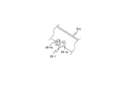
- the wall surface integrated defining portion 25 protrudes from the left wall surface 21a so that an end portion 25a on the opening side having a rectangular cross section with one of the four sides opening faces the left wall surface 21a. Further, the wall surface integral type defining portion 25 defines the position of the sealing member 23 by contacting the resin sheet 22 at the closing side end 25b opposite to the opening side end 25a.
- the wall-integrated defining portion 25 has a wall-integrated defining portion that protrudes from the left wall surface 21a so that one opening side end portion 25-1a having an H-shaped cross section faces the left wall surface 21a. 25-1.
- the wall surface integral type defining portion 25-1 defines the position of the sealing member 23 by contacting the resin sheet 22 at the end portion 25-1b on the other opening side.
- the wall surface integrated defining portion 25 is a rectangular parallelepiped, and is a wall surface integrated defining portion 25-2 protruding from the left wall surface 21a so that one end portion 25-2a faces the left wall surface 21a. There may be.
- the wall surface integral type defining portion 25-2 defines the position of the sealing member 23 by contacting the resin sheet 22 at the other end portion 25-2b.
- one or more of the wall surface integral defining portions 25-2 may be arranged in pairs, or one or more single wall surface integral defining portions 25-2 may be disposed.
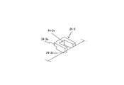
- the claw portion integrated defining portion 24 has two claw portions 24-1a (only one is shown) connected by the connection portion 24-1c.
- the claw portion integrated defining portion 24-1 protruding from the cover main body 21 may have a rectangular cross section with one side opened.
- the claw portion integrated defining portion 24-1 defines the position of the sealing member 23 by contacting the resin sheet 23 at the end portion 24-1d on the opening portion 24-1e side.
- the claw portion integrated defining portion 24 has a claw portion in which a claw portion 24-2a (only one is shown) and a defining surface 24d are integrally provided on each convex portion not connected by the connecting portion. It may be an integral defining part 24-2.
- the claw portion integrated defining portion 24-2 protrudes from the cover main body 21 in a rectangular cross section in which one of the four sides is open, and comes into contact with the resin sheet 23 at the end portion 24-2d on the opening portion 24-2e side. This defines the position of the sealing member 23.
- the lid portion 20 slides in a state where the sealing member 23 is in contact with the flat surface portion 12 and is pressed (sliding direction D ⁇ b> 1), and the claw portions 24 a and 24 b are engaged with the main body portion 10. By doing so, the mobile phone 1 is attached.
- the lid 20 may be a lid 20-1 that does not slide but is fitted into the main body 10 (inset direction D2) and attached to the mobile phone 1.
- a plurality of defining portions 26 that come into contact with the inner peripheral surface 22-1a of the frame-shaped resin sheet 22-1 are used. May be arranged on the lid 20.
- four defining portions 26 are arranged on each of the left and right sides of the lid portion 20 and two on the front and rear sides.
- a plurality of defining portions 26 that abut on the inner peripheral surface 22-1a of the frame-shaped resin sheet 22-1 and a plurality of defining portions 27 that abut on the outer peripheral surface 22-1b are lids. It may be arranged in the section 20. In the example of FIG. 19, two defining portions 26 are disposed on the front, rear, left, and right sides of the lid portion 20.
- the defining portion 26 is near the corner of the sealing member 23 (at the front end in the sliding direction D1 in FIG. 10), like the wall-integrated defining portion 25 on the back side. By being arranged in the vicinity or in the vicinity of the rear end, the position of the sealing member 23 can be more reliably defined.
- the sealing member 23 is disposed on the lid 20 (resin sheet 22) side.
- the sealing member 23 is disposed on the mobile phone 1 side, and the planar portion (contact surface). 12 may be provided on the lid 20 side.
- claw part integrated type defining part 24 is integrated with the front end side claw parts 24a and 24b. You may make it provide a part integrally.
- the sealing member 22 may be positioned from two directions, such as contacting two sides of the resin sheet 22.
- the planar portion 12 formed on the same plane has been described as an example.
- the contact surface is preferably a flat surface. However, it does not have to be completely flat, for example, it can be a curved surface.
- the battery housing portion 11 has been described as an example of the waterproof region.
- the lid portion 20 can be provided in a waterproof region other than the battery housing portion 11.
- the lid portion 20 includes the sealing member 23 and the defining portions 24 to 27.
- the sealing member 23 is in contact with the flat portion (contact surface) 12 formed on the same surface of the main body portion 10 over the entire circumference of the battery storage region (waterproof region) 11, and the battery storage region 11 is sealed.
- the defining portions 24 to 27 define the position of the sealing member 23.
- the defining portions 24 to 27 define the position of the sealing member 23 arranged in a limited space, the positional deviation and deformation of the sealing member 23 during the arrangement are prevented, and water stopping performance is ensured. can do.
- the sealing member 23 and the defining portions 24 to 27 are arranged not on the main body portion 10 side but on the lid portion 20 side. Therefore, it becomes possible to make it easy to arrange the sealing member 23 on the mobile phone 1, to improve the water stopping performance, and to easily replace the sealing member 23 that is a consumable part.
- the lid portion 20 includes claw portions 24a and 24b that engage with the main body portion 10, and the defining surface 24d (claw portion integrated defining portion 24) is integrated with the claw portions 24a and 24b. Is provided. Therefore, the position of the sealing member 23 can be defined with a simple configuration, and the portable electronic device 1 can be further downsized.
- the claw portion integrated defining portions 24-1 and 24-2 (regulating surfaces 24-1d and 24-2d) and the claw portions 24-1a and 24 are provided.
- -2a is integrally provided on the convex portion protruding from the lid portion 20 in a rectangular cross section in which one of the four sides is open.
- the defining portions 24-1 and 24-2 (regulating surfaces 24-1d and 24-2d) are sealed at the end portions 4-1d and 24-2d on the side of the opening portions 24-1e and 24-2e of the convex portion.
- the position of the member 23 is defined.
- the claw portions 24-1a and 24-2a are provided at the end portion on the closing side opposite to the end portions 24-1d and 24-2d on the opening side. Therefore, the position of the sealing member 23 can be defined more accurately with a simple configuration.
- the lid portion 20 is provided integrally with the two claw portions 24a and 24b that engage with the main body portion 10 and the two claw portions 24a and 24b, and these two claw portions 24a and 24b. And a connecting portion 24c for connecting the two.
- the claw part integrated defining part 24 (regulating surface 24d) is provided integrally with the two claw parts 24a, 24b and the connecting part 24c. Therefore, the position of the sealing member 23 can be defined more accurately with a simple configuration.
- the wall surface integrated defining portion 25 is provided integrally with the left wall surface 21 a so as to protrude from the left wall surface (wall surface) 21 a erected around the lid portion 20. Therefore, a simple configuration can be achieved, and the portable electronic device 1 can be further reduced in size.
- the wall surface integral type defining portion 25 has an opening-side end portion 25a having a rectangular cross section in which one side of the four sides is open. It protrudes from the left wall surface 21a so as to face the wall surface 21a. Further, the wall surface integrated defining portion 25 defines the position of the sealing member 23 at the closing end portion 25b opposite to the opening end portion 25a. Therefore, the position of the sealing member 23 can be defined while suppressing sink marks generated on the wall surface during molding when the closed portion side is directed to the wall surface.
- the wall surface integral type defining portion 25-1 is such that one opening side end portion 25-1a having an H-shaped cross section faces the left wall surface (wall surface) 21a.
- the position of the sealing member 23 is defined at the end 25-1b on the other opening side. Therefore, the position of the sealing member 23 can be defined more accurately while suppressing sink marks generated on the wall surface.
- the position of the sealing member 23 can be defined with a simple configuration.
- the cover part 20 is equipped with the resin sheet 22 by which the sealing member 23 was formed in the surface. Therefore, the sealing member 23 can be arranged easily and reliably. Furthermore, compared to a metal plate, the weight can be reduced and the radio wave for charging the battery 30 can be prevented from being blocked. Moreover, the attachment / detachment operation of the lid portion 20 can be facilitated as compared with the case where the cover body 21 and the resin sheet 22 are separate and have a double lid structure.
- the defining portion 20 defines the position of the sealing member 23 by contacting the resin sheet 22. Therefore, the position of the sealing member 23 can be defined more accurately.
- the lid portion 20 has a frame-shaped resin.
- the position of the sealing member 23 can be more accurately defined by providing a plurality of defining portions 26 that abut on the inner peripheral surface 22-1a of the sheet 22-1. Further, by using the frame-shaped resin sheet 22-1, the distance between the battery 30 and the cover body 21 can be shortened, and the mobile phone 1 can be downsized particularly in the battery thickness direction.
- the lid 20 has a plurality of defining portions 26 that abut on the inner peripheral surface 22-1a of the frame-shaped resin sheet 22-1 and a plurality of defining portions 27 that abut on the outer peripheral surface 22-1b of the resin sheet 22. , The position of the sealing member 23 can be more accurately defined.
- the above-described lid part (waterproof cover) 20 can reduce the size of the portable electronic device 1 and stop the battery housing part 11. Water performance can be ensured.
Landscapes
- Engineering & Computer Science (AREA)
- Signal Processing (AREA)
- Computer Networks & Wireless Communication (AREA)
- Chemical & Material Sciences (AREA)
- Chemical Kinetics & Catalysis (AREA)
- Electrochemistry (AREA)
- General Chemical & Material Sciences (AREA)
- Telephone Set Structure (AREA)
- Casings For Electric Apparatus (AREA)
- Battery Mounting, Suspending (AREA)
Abstract
Description
また、止水パッキンの変形を防止する変形防止リブが知られている。
図2は、蓋部20を内側から見た斜視図である。
図1に示す携帯電話機1は、本体部10と、防水カバーである蓋部20と、を有する。携帯電話機1は、携帯型電子機器の一例である。
10 本体部
11 電池収納部
12 平面部
20 蓋部
21 カバー本体
21a 左壁面
21b 右壁面
21c 底壁面
22 樹脂シート
23 封止部材
23a 封止ベース部
23b 突出部
24 爪部一体型規定部
24a,24b 爪部
24c 連結部
24d 規定面
24e 開口部
25 壁面一体型規定部
25a 開口側端部
25b 閉口側端部
26,27 規定部
30 電池
Claims (15)
- 防水領域を備える本体部と、前記防水領域を覆う蓋部と、を有する携帯型電子機器であって、
前記蓋部と前記本体部とのうち一方は、他方の同一面上に形成された接触面に対して前記防水領域の周方向の全周に亘って接触し該防水領域を封止する封止部材と、該封止部材の位置を規定する規定部と、を備える、
ことを特徴とする携帯型電子機器。 - 前記蓋部は、前記封止部材と前記規定部とを備えることを特徴とする請求項1に記載の携帯型電子機器。
- 前記蓋部は、前記本体部に係合する爪部を更に備え、
前記規定部は、前記爪部と一体に設けられている、
ことを特徴とする請求項2に記載の携帯型電子機器。 - 前記規定部と前記爪部とは、4辺のうちの1辺が開口する断面矩形状に前記蓋部から突出する凸部に一体に設けられ、
前記規定部は、前記凸部の開口側の端部において前記封止部材の位置を規定し、
前記爪部は、前記開口側の端部とは反対側の閉口側の端部に設けられている、
ことを特徴とする請求項3に記載の携帯型電子機器。 - 前記蓋部は、前記本体部に係合する2つの爪部と、該2つの爪部と一体に設けられ該2つの爪部を連結する連結部と、を更に備え、
前記規定部は、前記2つの爪部および前記連結部と一体に設けられている、
ことを特徴とする請求項2に記載の携帯型電子機器。 - 前記規定部は、前記蓋部の周囲において立設された壁面から突出するように該壁面と一体に設けられていることを特徴とする請求項2に記載の携帯型電子機器。
- 前記規定部は、4辺のうちの1辺が開口する断面矩形状の開口側の端部が前記壁面に対向するように該壁面から突出し、前記開口側の端部とは反対側の閉口側の端部において前記封止部材の位置を規定することを特徴とする請求項6に記載の携帯型電子機器。
- 前記規定部は、断面H字形状の一方の開口側の端部が前記壁面に対向するように該壁面から突出し、他方の開口側の端部において前記封止部材の位置を規定することを特徴とする請求項6に記載の携帯型電子機器。
- 前記規定部は、前記蓋部の周囲において立設する壁面であることを特徴とする請求項2に記載の携帯型電子機器。
- 前記蓋部は、表面に前記封止部材が形成された樹脂シートを更に備えることを特徴とする請求項2に記載の携帯型電子機器。
- 前記規定部は、前記樹脂シートに当接することで、前記封止部材の位置を規定することを特徴とする請求項10に記載の携帯型電子機器。
- 前記樹脂シートは、前記防水領域の周方向の全周に亘って形成された枠形状を呈し、
前記蓋部は、枠形状の前記樹脂シートの内周面に当接する複数の前記規定部を備える、ことを特徴とする請求項11に記載の携帯型電子機器。 - 前記蓋部は、前記樹脂シートの外周面に当接する複数の前記規定部を更に備えることを特徴とする請求項12に記載の携帯型電子機器。
- 前記防水領域は、電池収納部であることを特徴とする、請求項1に記載の携帯型電子機器。
- 携帯型電子機器の本体部の防水領域を覆う蓋部である防水カバーであって、
前記本体部の前記防水領域の周囲の同一面上に形成された接触面に対して前記防水領域の周方向の全周に亘って接触し、該防水領域を封止する封止部材と、
前記封止部材の位置を規定する規定部と、
を有することを特徴とする防水カバー。
Priority Applications (5)
| Application Number | Priority Date | Filing Date | Title |
|---|---|---|---|
| PCT/JP2011/063378 WO2012169068A1 (ja) | 2011-06-10 | 2011-06-10 | 携帯型電子機器、および、防水カバー |
| CN201180071307.5A CN103563340B (zh) | 2011-06-10 | 2011-06-10 | 便携式电子设备及防水盖 |
| KR1020137031313A KR101590688B1 (ko) | 2011-06-10 | 2011-06-10 | 휴대형 전자 기기 및 방수 커버 |
| JP2013519332A JP5655944B2 (ja) | 2011-06-10 | 2011-06-10 | 携帯型電子機器、および、防水カバー |
| US14/070,049 US9338264B2 (en) | 2011-06-10 | 2013-11-01 | Mobile electronic device and waterproof cover |
Applications Claiming Priority (1)
| Application Number | Priority Date | Filing Date | Title |
|---|---|---|---|
| PCT/JP2011/063378 WO2012169068A1 (ja) | 2011-06-10 | 2011-06-10 | 携帯型電子機器、および、防水カバー |
Related Child Applications (1)
| Application Number | Title | Priority Date | Filing Date |
|---|---|---|---|
| US14/070,049 Continuation US9338264B2 (en) | 2011-06-10 | 2013-11-01 | Mobile electronic device and waterproof cover |
Publications (1)
| Publication Number | Publication Date |
|---|---|
| WO2012169068A1 true WO2012169068A1 (ja) | 2012-12-13 |
Family
ID=47295668
Family Applications (1)
| Application Number | Title | Priority Date | Filing Date |
|---|---|---|---|
| PCT/JP2011/063378 Ceased WO2012169068A1 (ja) | 2011-06-10 | 2011-06-10 | 携帯型電子機器、および、防水カバー |
Country Status (5)
| Country | Link |
|---|---|
| US (1) | US9338264B2 (ja) |
| JP (1) | JP5655944B2 (ja) |
| KR (1) | KR101590688B1 (ja) |
| CN (1) | CN103563340B (ja) |
| WO (1) | WO2012169068A1 (ja) |
Cited By (1)
| Publication number | Priority date | Publication date | Assignee | Title |
|---|---|---|---|---|
| JP2023165174A (ja) * | 2022-05-02 | 2023-11-15 | トヨタ自動車株式会社 | 蓄電装置 |
Families Citing this family (6)
| Publication number | Priority date | Publication date | Assignee | Title |
|---|---|---|---|---|
| JP6233168B2 (ja) * | 2014-04-18 | 2017-11-22 | 株式会社豊田自動織機 | 電池パック |
| US9800713B2 (en) | 2014-09-12 | 2017-10-24 | Hzo, Inc. | Moisture detection response |
| US9939398B2 (en) | 2014-09-12 | 2018-04-10 | Hzo, Inc. | Detecting moisture with an antenna |
| US9866256B2 (en) * | 2015-12-21 | 2018-01-09 | Panasonic Intellectual Property Management Co., Ltd. | Electronic apparatus |
| CN110740206B (zh) * | 2019-09-25 | 2021-11-26 | 云谷(固安)科技有限公司 | 终端保护装置及电子设备 |
| EP4286980A4 (en) | 2021-07-14 | 2024-09-04 | Samsung Electronics Co., Ltd. | Electronic device comprising battery cover fastening structure |
Citations (4)
| Publication number | Priority date | Publication date | Assignee | Title |
|---|---|---|---|---|
| JP2009094136A (ja) * | 2007-10-04 | 2009-04-30 | Casio Hitachi Mobile Communications Co Ltd | 防水構造及び電子機器の筐体 |
| JP2010080910A (ja) * | 2008-08-27 | 2010-04-08 | Nok Corp | 電子機器のシール構造 |
| JP2010268282A (ja) * | 2009-05-15 | 2010-11-25 | Panasonic Corp | 携帯端末装置 |
| JP2011044888A (ja) * | 2009-08-20 | 2011-03-03 | Nec Corp | 防水筐体 |
Family Cites Families (4)
| Publication number | Priority date | Publication date | Assignee | Title |
|---|---|---|---|---|
| KR100546965B1 (ko) * | 2005-01-31 | 2006-01-26 | (주)블루버드 소프트 | 모바일 단말기 |
| CN201422120Y (zh) * | 2009-03-16 | 2010-03-10 | 姚牡丹 | 一种手机保护装置 |
| JP2011010164A (ja) | 2009-06-29 | 2011-01-13 | Panasonic Corp | 携帯端末装置 |
| KR20110041384A (ko) | 2009-10-15 | 2011-04-21 | 삼성전자주식회사 | 휴대용 단말기의 방수 구조 |
-
2011
- 2011-06-10 CN CN201180071307.5A patent/CN103563340B/zh not_active Expired - Fee Related
- 2011-06-10 JP JP2013519332A patent/JP5655944B2/ja not_active Expired - Fee Related
- 2011-06-10 KR KR1020137031313A patent/KR101590688B1/ko not_active Expired - Fee Related
- 2011-06-10 WO PCT/JP2011/063378 patent/WO2012169068A1/ja not_active Ceased
-
2013
- 2013-11-01 US US14/070,049 patent/US9338264B2/en not_active Expired - Fee Related
Patent Citations (4)
| Publication number | Priority date | Publication date | Assignee | Title |
|---|---|---|---|---|
| JP2009094136A (ja) * | 2007-10-04 | 2009-04-30 | Casio Hitachi Mobile Communications Co Ltd | 防水構造及び電子機器の筐体 |
| JP2010080910A (ja) * | 2008-08-27 | 2010-04-08 | Nok Corp | 電子機器のシール構造 |
| JP2010268282A (ja) * | 2009-05-15 | 2010-11-25 | Panasonic Corp | 携帯端末装置 |
| JP2011044888A (ja) * | 2009-08-20 | 2011-03-03 | Nec Corp | 防水筐体 |
Cited By (2)
| Publication number | Priority date | Publication date | Assignee | Title |
|---|---|---|---|---|
| JP2023165174A (ja) * | 2022-05-02 | 2023-11-15 | トヨタ自動車株式会社 | 蓄電装置 |
| JP7697405B2 (ja) | 2022-05-02 | 2025-06-24 | トヨタ自動車株式会社 | 蓄電装置 |
Also Published As
| Publication number | Publication date |
|---|---|
| CN103563340A (zh) | 2014-02-05 |
| CN103563340B (zh) | 2016-08-17 |
| JPWO2012169068A1 (ja) | 2015-02-23 |
| JP5655944B2 (ja) | 2015-01-21 |
| US20140057688A1 (en) | 2014-02-27 |
| KR101590688B1 (ko) | 2016-02-01 |
| KR20140017647A (ko) | 2014-02-11 |
| US9338264B2 (en) | 2016-05-10 |
Similar Documents
| Publication | Publication Date | Title |
|---|---|---|
| JP5655944B2 (ja) | 携帯型電子機器、および、防水カバー | |
| US9338910B2 (en) | Electronic device and sealed structure | |
| JP5262798B2 (ja) | ケースの防水構造およびこれを備えた電子機器 | |
| JP4460622B1 (ja) | 携帯端末装置 | |
| JP2023503631A5 (ja) | ||
| US20130146323A1 (en) | Gasket and electronic device | |
| JP5500638B2 (ja) | 防水型筐体及びこれを備えた電子機器 | |
| CN106453707A (zh) | 一种超薄电子装置 | |
| US20150063618A1 (en) | Housing assembly | |
| JP2012013149A (ja) | パッキン構造 | |
| US8934623B2 (en) | Housing for electronic device | |
| JP2009295321A (ja) | 機器ケースの開閉部分の防水構造 | |
| JP2013101998A (ja) | 防水用蓋および電子機器 | |
| JP5488448B2 (ja) | 携帯機器 | |
| US20120236478A1 (en) | Battery cover assembly for electronic devices | |
| JP2012059552A (ja) | 電池収納部カバーおよび電子機器 | |
| CN103813673A (zh) | 保护结构、电子装置及该保护结构的制造方法 | |
| JP2012033827A (ja) | 筐体 | |
| JP2013207668A (ja) | シール部材およびそのシール部材を備えた携帯機器 | |
| JP7685415B2 (ja) | 携帯端末 | |
| JP5593780B2 (ja) | 筐体構造 | |
| CN104754903A (zh) | 电子装置 | |
| JP2011259279A (ja) | 携帯用電子機器 | |
| JP5700450B2 (ja) | 筺体の防水構造およびそれを備える電子機器 | |
| JP5420304B2 (ja) | 携帯電子機器 |
Legal Events
| Date | Code | Title | Description |
|---|---|---|---|
| 121 | Ep: the epo has been informed by wipo that ep was designated in this application |
Ref document number: 11867179 Country of ref document: EP Kind code of ref document: A1 |
|
| ENP | Entry into the national phase |
Ref document number: 2013519332 Country of ref document: JP Kind code of ref document: A |
|
| ENP | Entry into the national phase |
Ref document number: 20137031313 Country of ref document: KR Kind code of ref document: A |
|
| NENP | Non-entry into the national phase |
Ref country code: DE |
|
| 122 | Ep: pct application non-entry in european phase |
Ref document number: 11867179 Country of ref document: EP Kind code of ref document: A1 |