WO2012169023A1 - 車両の電源システムおよび車両 - Google Patents
車両の電源システムおよび車両 Download PDFInfo
- Publication number
- WO2012169023A1 WO2012169023A1 PCT/JP2011/063153 JP2011063153W WO2012169023A1 WO 2012169023 A1 WO2012169023 A1 WO 2012169023A1 JP 2011063153 W JP2011063153 W JP 2011063153W WO 2012169023 A1 WO2012169023 A1 WO 2012169023A1
- Authority
- WO
- WIPO (PCT)
- Prior art keywords
- battery
- auxiliary battery
- charger
- vehicle
- voltage
- Prior art date
- Legal status (The legal status is an assumption and is not a legal conclusion. Google has not performed a legal analysis and makes no representation as to the accuracy of the status listed.)
- Ceased
Links
Images





Classifications
-
- B—PERFORMING OPERATIONS; TRANSPORTING
- B60—VEHICLES IN GENERAL
- B60L—PROPULSION OF ELECTRICALLY-PROPELLED VEHICLES; SUPPLYING ELECTRIC POWER FOR AUXILIARY EQUIPMENT OF ELECTRICALLY-PROPELLED VEHICLES; ELECTRODYNAMIC BRAKE SYSTEMS FOR VEHICLES IN GENERAL; MAGNETIC SUSPENSION OR LEVITATION FOR VEHICLES; MONITORING OPERATING VARIABLES OF ELECTRICALLY-PROPELLED VEHICLES; ELECTRIC SAFETY DEVICES FOR ELECTRICALLY-PROPELLED VEHICLES
- B60L3/00—Electric devices on electrically-propelled vehicles for safety purposes; Monitoring operating variables, e.g. speed, deceleration or energy consumption
-
- B—PERFORMING OPERATIONS; TRANSPORTING
- B60—VEHICLES IN GENERAL
- B60L—PROPULSION OF ELECTRICALLY-PROPELLED VEHICLES; SUPPLYING ELECTRIC POWER FOR AUXILIARY EQUIPMENT OF ELECTRICALLY-PROPELLED VEHICLES; ELECTRODYNAMIC BRAKE SYSTEMS FOR VEHICLES IN GENERAL; MAGNETIC SUSPENSION OR LEVITATION FOR VEHICLES; MONITORING OPERATING VARIABLES OF ELECTRICALLY-PROPELLED VEHICLES; ELECTRIC SAFETY DEVICES FOR ELECTRICALLY-PROPELLED VEHICLES
- B60L58/00—Methods or circuit arrangements for monitoring or controlling batteries or fuel cells, specially adapted for electric vehicles
- B60L58/10—Methods or circuit arrangements for monitoring or controlling batteries or fuel cells, specially adapted for electric vehicles for monitoring or controlling batteries
- B60L58/12—Methods or circuit arrangements for monitoring or controlling batteries or fuel cells, specially adapted for electric vehicles for monitoring or controlling batteries responding to state of charge [SoC]
-
- B—PERFORMING OPERATIONS; TRANSPORTING
- B60—VEHICLES IN GENERAL
- B60L—PROPULSION OF ELECTRICALLY-PROPELLED VEHICLES; SUPPLYING ELECTRIC POWER FOR AUXILIARY EQUIPMENT OF ELECTRICALLY-PROPELLED VEHICLES; ELECTRODYNAMIC BRAKE SYSTEMS FOR VEHICLES IN GENERAL; MAGNETIC SUSPENSION OR LEVITATION FOR VEHICLES; MONITORING OPERATING VARIABLES OF ELECTRICALLY-PROPELLED VEHICLES; ELECTRIC SAFETY DEVICES FOR ELECTRICALLY-PROPELLED VEHICLES
- B60L53/00—Methods of charging batteries, specially adapted for electric vehicles; Charging stations or on-board charging equipment therefor; Exchange of energy storage elements in electric vehicles
- B60L53/20—Methods of charging batteries, specially adapted for electric vehicles; Charging stations or on-board charging equipment therefor; Exchange of energy storage elements in electric vehicles characterised by converters located in the vehicle
- B60L53/22—Constructional details or arrangements of charging converters specially adapted for charging electric vehicles
-
- B—PERFORMING OPERATIONS; TRANSPORTING
- B60—VEHICLES IN GENERAL
- B60L—PROPULSION OF ELECTRICALLY-PROPELLED VEHICLES; SUPPLYING ELECTRIC POWER FOR AUXILIARY EQUIPMENT OF ELECTRICALLY-PROPELLED VEHICLES; ELECTRODYNAMIC BRAKE SYSTEMS FOR VEHICLES IN GENERAL; MAGNETIC SUSPENSION OR LEVITATION FOR VEHICLES; MONITORING OPERATING VARIABLES OF ELECTRICALLY-PROPELLED VEHICLES; ELECTRIC SAFETY DEVICES FOR ELECTRICALLY-PROPELLED VEHICLES
- B60L58/00—Methods or circuit arrangements for monitoring or controlling batteries or fuel cells, specially adapted for electric vehicles
- B60L58/10—Methods or circuit arrangements for monitoring or controlling batteries or fuel cells, specially adapted for electric vehicles for monitoring or controlling batteries
- B60L58/18—Methods or circuit arrangements for monitoring or controlling batteries or fuel cells, specially adapted for electric vehicles for monitoring or controlling batteries of two or more battery modules
-
- B—PERFORMING OPERATIONS; TRANSPORTING
- B60—VEHICLES IN GENERAL
- B60L—PROPULSION OF ELECTRICALLY-PROPELLED VEHICLES; SUPPLYING ELECTRIC POWER FOR AUXILIARY EQUIPMENT OF ELECTRICALLY-PROPELLED VEHICLES; ELECTRODYNAMIC BRAKE SYSTEMS FOR VEHICLES IN GENERAL; MAGNETIC SUSPENSION OR LEVITATION FOR VEHICLES; MONITORING OPERATING VARIABLES OF ELECTRICALLY-PROPELLED VEHICLES; ELECTRIC SAFETY DEVICES FOR ELECTRICALLY-PROPELLED VEHICLES
- B60L58/00—Methods or circuit arrangements for monitoring or controlling batteries or fuel cells, specially adapted for electric vehicles
- B60L58/10—Methods or circuit arrangements for monitoring or controlling batteries or fuel cells, specially adapted for electric vehicles for monitoring or controlling batteries
- B60L58/18—Methods or circuit arrangements for monitoring or controlling batteries or fuel cells, specially adapted for electric vehicles for monitoring or controlling batteries of two or more battery modules
- B60L58/20—Methods or circuit arrangements for monitoring or controlling batteries or fuel cells, specially adapted for electric vehicles for monitoring or controlling batteries of two or more battery modules having different nominal voltages
-
- B—PERFORMING OPERATIONS; TRANSPORTING
- B60—VEHICLES IN GENERAL
- B60L—PROPULSION OF ELECTRICALLY-PROPELLED VEHICLES; SUPPLYING ELECTRIC POWER FOR AUXILIARY EQUIPMENT OF ELECTRICALLY-PROPELLED VEHICLES; ELECTRODYNAMIC BRAKE SYSTEMS FOR VEHICLES IN GENERAL; MAGNETIC SUSPENSION OR LEVITATION FOR VEHICLES; MONITORING OPERATING VARIABLES OF ELECTRICALLY-PROPELLED VEHICLES; ELECTRIC SAFETY DEVICES FOR ELECTRICALLY-PROPELLED VEHICLES
- B60L2210/00—Converter types
- B60L2210/10—DC to DC converters
- B60L2210/12—Buck converters
-
- B—PERFORMING OPERATIONS; TRANSPORTING
- B60—VEHICLES IN GENERAL
- B60L—PROPULSION OF ELECTRICALLY-PROPELLED VEHICLES; SUPPLYING ELECTRIC POWER FOR AUXILIARY EQUIPMENT OF ELECTRICALLY-PROPELLED VEHICLES; ELECTRODYNAMIC BRAKE SYSTEMS FOR VEHICLES IN GENERAL; MAGNETIC SUSPENSION OR LEVITATION FOR VEHICLES; MONITORING OPERATING VARIABLES OF ELECTRICALLY-PROPELLED VEHICLES; ELECTRIC SAFETY DEVICES FOR ELECTRICALLY-PROPELLED VEHICLES
- B60L2210/00—Converter types
- B60L2210/10—DC to DC converters
- B60L2210/14—Boost converters
-
- Y—GENERAL TAGGING OF NEW TECHNOLOGICAL DEVELOPMENTS; GENERAL TAGGING OF CROSS-SECTIONAL TECHNOLOGIES SPANNING OVER SEVERAL SECTIONS OF THE IPC; TECHNICAL SUBJECTS COVERED BY FORMER USPC CROSS-REFERENCE ART COLLECTIONS [XRACs] AND DIGESTS
- Y02—TECHNOLOGIES OR APPLICATIONS FOR MITIGATION OR ADAPTATION AGAINST CLIMATE CHANGE
- Y02T—CLIMATE CHANGE MITIGATION TECHNOLOGIES RELATED TO TRANSPORTATION
- Y02T10/00—Road transport of goods or passengers
- Y02T10/60—Other road transportation technologies with climate change mitigation effect
- Y02T10/70—Energy storage systems for electromobility, e.g. batteries
-
- Y—GENERAL TAGGING OF NEW TECHNOLOGICAL DEVELOPMENTS; GENERAL TAGGING OF CROSS-SECTIONAL TECHNOLOGIES SPANNING OVER SEVERAL SECTIONS OF THE IPC; TECHNICAL SUBJECTS COVERED BY FORMER USPC CROSS-REFERENCE ART COLLECTIONS [XRACs] AND DIGESTS
- Y02—TECHNOLOGIES OR APPLICATIONS FOR MITIGATION OR ADAPTATION AGAINST CLIMATE CHANGE
- Y02T—CLIMATE CHANGE MITIGATION TECHNOLOGIES RELATED TO TRANSPORTATION
- Y02T10/00—Road transport of goods or passengers
- Y02T10/60—Other road transportation technologies with climate change mitigation effect
- Y02T10/7072—Electromobility specific charging systems or methods for batteries, ultracapacitors, supercapacitors or double-layer capacitors
-
- Y—GENERAL TAGGING OF NEW TECHNOLOGICAL DEVELOPMENTS; GENERAL TAGGING OF CROSS-SECTIONAL TECHNOLOGIES SPANNING OVER SEVERAL SECTIONS OF THE IPC; TECHNICAL SUBJECTS COVERED BY FORMER USPC CROSS-REFERENCE ART COLLECTIONS [XRACs] AND DIGESTS
- Y02—TECHNOLOGIES OR APPLICATIONS FOR MITIGATION OR ADAPTATION AGAINST CLIMATE CHANGE
- Y02T—CLIMATE CHANGE MITIGATION TECHNOLOGIES RELATED TO TRANSPORTATION
- Y02T10/00—Road transport of goods or passengers
- Y02T10/60—Other road transportation technologies with climate change mitigation effect
- Y02T10/72—Electric energy management in electromobility
-
- Y—GENERAL TAGGING OF NEW TECHNOLOGICAL DEVELOPMENTS; GENERAL TAGGING OF CROSS-SECTIONAL TECHNOLOGIES SPANNING OVER SEVERAL SECTIONS OF THE IPC; TECHNICAL SUBJECTS COVERED BY FORMER USPC CROSS-REFERENCE ART COLLECTIONS [XRACs] AND DIGESTS
- Y02—TECHNOLOGIES OR APPLICATIONS FOR MITIGATION OR ADAPTATION AGAINST CLIMATE CHANGE
- Y02T—CLIMATE CHANGE MITIGATION TECHNOLOGIES RELATED TO TRANSPORTATION
- Y02T90/00—Enabling technologies or technologies with a potential or indirect contribution to GHG emissions mitigation
- Y02T90/10—Technologies relating to charging of electric vehicles
- Y02T90/14—Plug-in electric vehicles
Definitions
- the present invention relates to a vehicle power supply system and a vehicle, and more particularly to a vehicle power supply system and a vehicle configured to be able to charge a battery using electric power supplied from an external power supply.
- Patent Document 1 discloses a charger that charges a main battery from an external power source, and a DC / DC that charges an auxiliary battery by reducing the voltage of the main battery.
- An electric vehicle including a DC converter is disclosed.
- the interlock function when reducing the number of parts by bidirectionalizing the charger itself, if the interlock function is not secured, if the charging plug is inserted during charging of the auxiliary battery, the voltage between the external power supply and the auxiliary battery There may be a short circuit between them. Further, if external charging is continued, the auxiliary battery may continue to be discharged and the auxiliary battery may be discharged.
- An object of the present invention is to provide a vehicle power supply system in which the number of parts for enabling both charging from an external power source to the main battery and charging from the main battery to the auxiliary battery is reduced, and a short circuit is reliably prevented. And providing a vehicle.
- the present invention is a power supply system for a vehicle, and converts a power supplied from an external power supply via a connection portion for connecting an external power supply, a main battery, an auxiliary battery, and the connection portion.
- a charger configured to enable a first charging operation for charging the main battery and a second charging operation for converting the power of the main battery to charge the auxiliary battery, and any one of the connection unit and the auxiliary battery
- a connection switching unit that selects one of them and connects it to the charger.
- connection switching unit is configured such that either the connection unit or the auxiliary battery is selectively connected to the charger.
- the power supply system of the vehicle further includes a control device that controls the charger and the connection switching unit.
- the control device switches the connection switching unit based on whether or not the external power source is connected to the connection unit and the voltage of the auxiliary battery.
- the control device when the external power supply is connected to the connection unit and the voltage of the auxiliary battery is lower than a predetermined value, the control device includes a connection switching unit so as to connect the auxiliary battery and the charger. Control.
- the present invention is a vehicle including any one of the power supply systems described above.
- the number of parts for enabling both charging from the external power supply to the main battery and charging from the main battery to the auxiliary battery is reduced, and a short circuit between the external power supply and the auxiliary battery is achieved. Is reliably prevented.
- FIG. 1 is an overall block diagram of a vehicle 100 equipped with a power supply system according to an embodiment of the present invention. It is a figure which shows the structure of vehicle 100A of the 1st examination example. It is a figure which shows the structure of the vehicle 100B of the 2nd examination example. It is a figure for demonstrating how the changeover switch 250 is controlled.
- 2 is a flowchart for explaining control of changeover switch 250 and charger 200 executed by control device 160 of FIG. 1. It is a figure which shows the flow of electric power when the charge plug is not inserted in the inlet. It is a figure which shows the flow of electric power when the charge plug is inserted in the inlet but the voltage of the auxiliary battery is lowered. It is a figure which shows the flow of electric power when the charge plug is inserted in the inlet and the auxiliary battery is fully charged. It is the figure which showed the other example of the changeover switch.
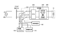
- FIG. 1 is an overall block diagram of a vehicle 100 equipped with a power supply system according to an embodiment of the present invention.
- vehicle 100 includes a main battery 10, an inverter 120 as a driving device, a motor generator 130, a control device (hereinafter also referred to as an ECU (Electronic Control Unit)) 160, and a detection unit 322.
- the motor generator 130 rotates the drive wheels via a power transmission gear.
- the main battery 10 is a power storage element configured to be chargeable / dischargeable.
- the main battery 10 includes, for example, a secondary battery such as a lithium ion battery, a nickel metal hydride battery, or a lead storage battery, and a storage element such as an electric double layer capacitor.
- the positive end and the negative end of the main battery 10 are connected to an inverter 120 for driving a motor generator 130 that is a load. Then, main battery 10 supplies electric power for generating driving force of vehicle 100 to inverter 120. Main battery 10 stores the electric power generated by motor generator 130. Although the output voltage of the main battery 10 is not limited, it is 200V, for example.
- the motor generator 130 is an AC rotating electric machine, for example, a permanent magnet type synchronous motor including a rotor in which a permanent magnet is embedded.
- the output torque of the motor generator 130 is transmitted to the drive wheels via a power transmission gear constituted by a speed reducer and a power split mechanism, thereby causing the vehicle 100 to travel.
- Motor generator 130 can generate electric power by the rotational force of the drive wheels during regenerative braking operation of vehicle 100.
- the generated power is converted into charging power for the main battery 10 by the inverter 120.
- a necessary vehicle driving force is generated by operating the engine and the motor generator 130 in a coordinated manner.
- vehicle 100 in the present embodiment indicates a vehicle equipped with an electric motor for generating vehicle driving force, and is a hybrid vehicle that generates vehicle driving force by an engine and an electric motor, an electric vehicle that is not equipped with an engine, and a fuel cell. Includes automobiles.
- the vehicle power supply system is configured by a portion excluding the inverter 120 and the motor generator 130 from the illustrated configuration of the vehicle 100.
- the power supply system further includes a charger 200, a changeover switch 250, an auxiliary battery 150, and an auxiliary load 170 as a low voltage system (auxiliary system) configuration.
- the auxiliary machine load 170 includes, for example, a headlight, an audio device, and the like.
- Auxiliary battery 150 is typically composed of a lead-acid battery.
- the output voltage of auxiliary battery 150 is lower than the output voltage of main battery 10 and is, for example, about 12V.
- the terminal A of the changeover switch 250 is connected to the inlet 320.
- a plug 310 provided at the tip of a charging cable from the external power source 300 is connected to the inlet 320 when the main battery 10 is charged.
- Terminal B of changeover switch 250 is connected to auxiliary battery 150 and auxiliary load 170.
- a terminal C of the changeover switch 250 is connected to the charger 200.
- the changeover switch 250 is configured to selectively connect the terminal C to one of the terminals A and B. Since it is such a structure, it is avoided that the terminal A and the terminal B are connected accidentally.
- the detection unit 322 detects whether the lid covering the inlet 320 is open or whether a plug is inserted in the inlet 320.
- the detection unit 322 transmits the detection result to the control device 160.
- Control device 160 detects the voltage of auxiliary battery 150.
- Control device 160 controls change-over switch 250 and charger 200 based on the detection result of detection unit 322 and the voltage of auxiliary battery 150.
- control device 160 includes a CPU (Central Processing Unit), a storage device, and an input / output buffer, and inputs signals from each sensor and outputs control signals to each device.
- the vehicle 100 and each device are controlled. Note that these controls are not limited to processing by software, and can be processed by dedicated hardware (electronic circuit).
- the control device 160 may be dedicated to charge control, and a vehicle control device may be provided.
- the charger 200 includes a PFC (Power Factor Correction) circuit 202 and a bidirectional DC / DC converter 204.
- the charger 200 operates as a charger that receives AC power from the external power source from the inlet 320 and converts the AC power into a charging voltage (DC voltage) of the main battery 10, and reduces the voltage of the main battery 10 to the auxiliary load 170. It also operates as a DC / DC converter that supplies or charges the auxiliary battery 150.
- FIG. 2 is a diagram illustrating a configuration of the vehicle 100A of the first study example.
- vehicle 100A includes a charger 200A, a main battery 10, a DC / DC converter 201A, an auxiliary battery 150, and an auxiliary load 170.
- the charger 200A includes a PFC circuit 202A and a DC / DC converter 204A.
- the voltage of the main battery 10 is not limited, it is 200V, for example, and the voltage of the auxiliary battery 150 is 12V, for example.
- the charger 200 ⁇ / b> A is connected between an inlet (plug insertion port) to which the external power source 300 is connected and the main battery 10.
- Charger 200 ⁇ / b> A charges main battery 10 by converting AC power supplied from external power supply 300 into DC.
- the PFC circuit 202A rectifies AC and improves the power factor.
- the DC / DC converter 204 ⁇ / b> A is configured to be able to send power only in one direction from the external power supply 300 toward the main battery 10.
- the DC / DC converter 204A for example, converts the AC power generated in the AC generation circuit that receives the DC power from the PFC circuit 202A into a voltage (boost) with an insulating transformer, and rectifies the DC power again with the rectifier circuit. Then, it can be configured to send to the main battery 10.
- the DC / DC converter 201A steps down the voltage of the main battery 10 and supplies it to the auxiliary battery 150 and the auxiliary load 170.
- the DC / DC converter 201A for example, converts the AC power generated by the AC generator circuit to which the DC power of the main battery 10 is supplied into a voltage (step-down) with an insulating transformer, and again converts it into DC power with the rectifier circuit.
- the rectification may be performed and the auxiliary battery 150 and the auxiliary load 170 may be supplied.
- FIG. 3 is a diagram illustrating a configuration of the vehicle 100B of the second study example.
- vehicle 100 ⁇ / b> B includes a charger 200, a main battery 10, an auxiliary battery 150, and an auxiliary load 170.
- the charger 200 includes a PFC circuit 202 and a DC / DC converter 204.
- the voltage of the main battery 10 is not limited, it is 200V, for example, and the voltage of the auxiliary battery 150 is 12V, for example.
- the charger 200 is connected between the inlet (plug insertion port) to which the external power source 300 is connected and the main battery 10.
- the charger 200 charges the main battery 10 by converting AC power supplied from the external power source 300 into DC.
- the DC / DC converter 204 is configured to be able to send electric power in both directions, thereby reducing the DC power of the main battery 10 and passing the PFC circuit 202 through the auxiliary battery 150. And DC power can be supplied to the auxiliary load 170.
- the auxiliary battery 150 is always in a discharged state. Therefore, when the voltage of the auxiliary battery 150 falls below a certain value due to power consumption in the auxiliary load 170, etc.
- the load on the vehicle including the control ECU) stops, and there is a possibility of falling into a state where charging is not possible or a vehicle is not running.
- the vehicle 100 in FIG. 1 is provided with a changeover switch 250 that mechanically switches between an external AC power source and an auxiliary battery.
- the changeover switch 250 is an interlock switch in which the reciprocating path of power transmission is switched in conjunction, and is configured to selectively connect the terminal C to one of the terminals A and B. Since it is such a structure, it is avoided that the terminal A and the terminal B are connected accidentally. It is also avoided that the forward path (one input of the PFC circuit) of the power transmission path is connected to the external power source 300 and the return path (the other input of the PFC circuit) is connected to the auxiliary battery.
- the voltage of the auxiliary battery 150 is monitored while the main battery 10 is being charged, and immediately before the auxiliary battery 150 is raised, the mode for charging the main battery 10 is switched to the mode for charging the auxiliary battery 150.
- the control device 160 controls the changeover switch 250 and the charger 200.
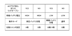
- FIG. 4 is a diagram for explaining how the changeover switch 250 is controlled.
- FIG. 4 shows how the operation mode and the changeover switch setting are determined for the combination of the detection item “AC plug insertion or lid open” and the detection result of the detection item “auxiliary battery voltage”. It is shown.
- the detection unit 322 in FIG. 1 detects that the plug 310 is inserted into the inlet 320, or the lid covering the inlet 320 is in an open state and the plug is opened. It indicates that it is detected that the insertion of 310 is possible, and in the case of “NO”, it indicates that neither is detected.
- auxiliary battery voltage is “HIGH” indicates that the voltage of the auxiliary battery 150 is higher than a threshold value for determining whether charging is necessary, and the case where the “auxiliary battery voltage” is “LOW” 150 indicates that the voltage is lower than the threshold.
- the operation mode is set to “high voltage battery charging mode”.
- the selector switch 250 selects the terminal A.
- the charger 200 is controlled so that the main battery 10 is charged from the external power supply 300.
- the operation mode is set to “auxiliary battery charging mode” and the changeover switch 250 is connected to the terminal B.
- the selection and the selection of the terminal A are appropriately changed.
- the charger 200 is controlled so that the main battery 10 is charged from the external power source 300 in principle.
- the auxiliary battery 150 needs to be charged. Therefore, the selection of the changeover switch 250 is switched from the terminal A to the terminal B, and the charger 200 is controlled so that the auxiliary battery 150 is charged from the main battery 10.
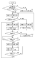
- FIG. 5 is a flowchart for explaining control of the changeover switch 250 and the charger 200 executed by the control device 160 of FIG.
- control device 160 determines whether the plug insertion opening / closing state is an open state or not. Specifically, it is determined whether or not the lid covering the inlet 320 is in an open state.
- the detection unit 322 may detect whether the plug 310 is inserted into the inlet 320 (or whether it is attached) instead of detecting opening / closing of the lid.
- step S1 when the plug insertion slot is closed or the plug 310 is not inserted into the inlet 320, the process proceeds to step S2, and the changeover switch 250 is set to select the terminal B.
- FIG. 6 is a diagram showing the flow of power when the charging plug is not inserted into the inlet. Since the changeover switch 250 selects the terminal B and the charger 200 is controlled to step down the voltage of the main battery 10, the charging power is directed toward the auxiliary battery 150 as shown by the arrow in FIG. Will be sent.
- step S1 if the plug insertion slot is open or the plug 310 is inserted into the inlet 320 in step S1, the process proceeds to step S3.
- step S3 the control device 160 detects the voltage of the auxiliary battery 150. Since the charger 200 is used while the main battery 10 is continuously charged, the auxiliary battery 150 cannot be charged. Therefore, in step S3, the voltage of the auxiliary battery 150 is periodically monitored.
- step S4 it is determined whether or not the voltage of the auxiliary battery 150 is normal. Specifically, it is determined whether or not the voltage of auxiliary battery 150 is higher than a threshold voltage that requires charging.
- step S4 if the voltage determination is not normal, that is, if the voltage falls below the threshold voltage and charging is required, the process proceeds to step S5, and the selector switch 250 is switched from terminal A to terminal B. .
- step S6 the control of the charger 200 is switched so as to step down the voltage of the main battery 10 to the auxiliary battery 150 to charge the auxiliary battery 150.
- FIG. 7 is a diagram showing the flow of electric power when the charging plug is inserted into the inlet but the voltage of the auxiliary battery is lowered. Since the changeover switch 250 selects the terminal B and the charger 200 is controlled to step down the voltage of the main battery 10, the charging power is directed toward the auxiliary battery 150 as shown by the arrow in FIG. Will be sent.
- step S6 after charging for a certain time in step S6, the process returns to step S3, and the voltage of auxiliary battery 150 is detected again.
- step S7 the changeover switch 250 is set to select the terminal A.
- step S8 the charger 200 is operated in the boost mode.
- FIG. 8 is a diagram showing the flow of power when the charging plug is inserted into the inlet and the auxiliary battery is sufficiently charged.
- the charger 200 is controlled. Therefore, charging power is sent from the external power supply 300 toward the main battery 10 as shown by the arrow in FIG.
- the external power supply voltage for example, AC 100V
- the charging voltage for example, DC 200V
- step S9 it is determined whether or not charging of main battery 10 is completed. Whether or not the charging of the main battery 10 has been completed is determined by whether or not an SOC (State Of Charge) calculated or estimated based on the charging voltage and charging current has reached an upper limit value corresponding to full charging, for example. .
- SOC State Of Charge
- step S9 when it is determined that the charging of the main battery 10 is completed, the process proceeds to step S10, and the control device 160 stops the operation of the charger 200. On the other hand, if the charging of the main battery 10 has not been completed in step S9, the process proceeds to step S11, and a time is waited until the time count reaches the threshold value tA (continuation of charging of the main battery 10) is performed. It is. When the predetermined time has elapsed and the time count reaches the threshold value tA, the process proceeds to step S12.
- auxiliary battery 150 when the charger 200 is charging the main battery 10, electric power is supplied from the auxiliary battery 150 to the auxiliary load 170, so that the auxiliary battery 150 may be discharged. This is because it is considered. If the auxiliary battery 150 is overdischarged, the operation of the auxiliary load 170 may be hindered. Since the auxiliary load 170 includes a portion for supplying power to the control device 160, it is desirable to periodically charge the auxiliary battery 150 in order to continue the charging operation.
- step S12 the control device 160 switches the terminal selection of the changeover switch 250 from the terminal A to the terminal B. Further, in step S13, the auxiliary battery 150 is charged by switching the control of the charger 200 so as to step down the voltage of the main battery 10 to the auxiliary battery 150. At this time, power is sent as shown by the arrows in FIG. Until charging for a certain amount of time is performed in step S14 (until the time count reaches threshold value tB), the process returns from step S14 to step S13, and charging of auxiliary battery 150 is performed.
- step S14 If the time count reaches the threshold value tB in step S14, the process returns to step S7, and the control is switched again so that the changeover switch 250 and the charger 200 are charged from the external power source 300 to the main battery 10.
- the terminal C on the charger 200 side is the common side (common: common), and the charging plug and the auxiliary circuit are the selection side. But it can be realized.
- FIG. 9 is a diagram showing another example of the selector switch.
- changeover switch 250 ⁇ / b> A has a movable section that moves, a first connection that connects charger 200 and external power supply 300, and a second connection that connects charger 200 and auxiliary battery 150. Switching between connection and. On the charger 200 side, two contacts are commonly connected outside the changeover switch 250A.
- the external power supply 300 and the auxiliary battery 150 are mechanically configured not to be short-circuited. It is preferable to use a selector switch that does not cause a mechanical short circuit, but even when two relays are controlled by separate control signals, combinations of control signals that simultaneously turn on the relays are prohibited. In this way, the control device may control.
- the vehicle power supply system converts the power supplied from the external power supply 300 via the inlet 320 for connecting the external power supply 300, the main battery 10, the auxiliary battery 150, and the inlet 320.
- a charger 200 configured to enable a first charging operation for charging main battery 10 and a second charging operation for converting power of main battery 10 to charge auxiliary battery 150, an inlet 320, and an auxiliary device.
- a changeover switch 250 that selects one of the batteries 150 and connects to the charger 200 is provided.
- changeover switch 250 (and changeover switch 250 ⁇ / b> A) is configured such that either one of inlet 320 and auxiliary battery 150 is selectively connected to charger 200. Composed.
- the vehicle power supply system further includes a controller 160 that controls the charger 200 and the changeover switch 250. As shown in FIGS. 4 and 5, control device 160 switches changeover switch 250 based on whether external power supply 300 is connected to inlet 320 and the voltage of auxiliary battery 150.
- the control device 160 when the external power source 300 is connected to the inlet 320 and the voltage of the auxiliary battery 150 is lower than a predetermined value, the control device 160 The changeover switch 250 is controlled so that the battery 150 and the charger 200 are connected.
- main battery 100, 100A, 100B vehicle, 120 inverter, 130 motor generator, 150 auxiliary battery, 160 controller, 170 auxiliary load, 200, 200A charger, 201A, 204, 204A converter, 202, 202A circuit 250, 250A selector switch, 300 external power supply, 310 plug, 320 inlet, 322 detector, A, B, C terminals.
Landscapes
- Engineering & Computer Science (AREA)
- Power Engineering (AREA)
- Transportation (AREA)
- Mechanical Engineering (AREA)
- Life Sciences & Earth Sciences (AREA)
- Sustainable Development (AREA)
- Sustainable Energy (AREA)
- Electric Propulsion And Braking For Vehicles (AREA)
- Charge And Discharge Circuits For Batteries Or The Like (AREA)
Abstract
車両の電源システムは、外部電源(300)を接続するためのインレット(320)と、メインバッテリ(10)と、補機バッテリ(150)と、インレット(320)を介して外部電源(300)から供給される電力を変換してメインバッテリ(10)を充電する第1充電動作と、メインバッテリ(10)の電力を変換して補機バッテリ(150)を充電する第2充電動作とが可能に構成された充電器(200)と、インレット(320)と補機バッテリ(150)とのいずれか一方を選択して充電器(200)に接続する切換スイッチ(250)とを備える。
Description
この発明は、車両の電源システムおよび車両に関し、特に外部電源から供給される電力を用いてバッテリを充電することが可能に構成された車両の電源システムおよび車両に関する。
近年、地球温暖化の防止のため二酸化炭素ガスの排出抑制の必要が高まっている。これを受けて、電気自動車やプラグインハイブリッド自動車など、電気エネルギで走行が可能であり、走行用の電気エネルギを保持する車載のバッテリに車両外部から充電が可能な車両も開発されている。
このような車両の例として、特開2009-27774号公報(特許文献1)は、外部電源からメインバッテリを充電する充電器と、メインバッテリの電圧を降圧して補機バッテリを充電するDC/DC変換器とを含む電動車両を開示する。
電気自動車などのような重く体格の大きい走行用のバッテリを搭載しかつ高効率走行を求められる車両では、小型軽量化の要求が高い。したがって、外部電源からメインバッテリを充電する充電器と、メインバッテリの電圧を降圧して補機バッテリを充電するDC/DC変換器とを別々に搭載するのでは、小型化、軽量化の妨げになるので、これらを一体化させたいというニーズがある。
しかし充電器自体を双方向化して部品点数を削減する場合、インターロック機能を確保しなければ補機バッテリの充電中に充電プラグが挿入されると外部電源の電圧と補機バッテリの電圧との間で短絡が生じる可能性がある。また、外部充電を継続して行なうと、補機バッテリが放電し続けることにより補機バッテリ上がりが発生する可能性がある。
この発明の目的は、外部電源からメインバッテリへの充電とメインバッテリから補機バッテリへの充電の両方を可能とするための部品点数が削減され、かつ短絡が確実に防止された車両の電源システムおよび車両を提供することである。
この発明は、要約すると、車両の電源システムであって、外部電源を接続するための接続部と、メインバッテリと、補機バッテリと、接続部を介して外部電源から供給される電力を変換してメインバッテリを充電する第1充電動作と、メインバッテリの電力を変換して補機バッテリを充電する第2充電動作とが可能に構成された充電器と、接続部と補機バッテリとのいずれか一方を選択して充電器に接続する接続切換部とを備える。
好ましくは、接続切換部は、接続部と補機バッテリとのいずれか一方が選択的に充電器に接続されるように構成される。
より好ましくは、車両の電源システムは、充電器および接続切換部を制御する制御装置をさらに備える。制御装置は、接続部への外部電源の接続の有無と補機バッテリの電圧とに基づいて、接続切換部を切換える。
さらに好ましくは、制御装置は、接続部に外部電源が接続されており、かつ補機バッテリの電圧が所定値より低い場合には、補機バッテリと充電器とを接続するように接続切換部を制御する。
この発明は、他の局面では、上記いずれかの電源システムを備える車両である。
本発明によれば、外部電源からメインバッテリへの充電とメインバッテリから補機バッテリへの充電の両方を可能とするための部品点数が削減され、かつ外部電源と補機バッテリとの間の短絡が確実に防止される。
以下、本発明の実施の形態について、図面を参照しながら詳細に説明する。なお、図中同一または相当部分には同一符号を付してその説明は繰り返さない。
図1は、本発明の実施の形態の電源システムを搭載した車両100の全体ブロック図である。
図1を参照して、車両100は、メインバッテリ10と、駆動装置であるインバータ120と、モータジェネレータ130と、制御装置(以下、ECU(Electronic Control Unit)とも称する。)160と、検出部322とを備える。図示しないが、モータジェネレータ130は動力伝達ギアを介して駆動輪を回転させる。
メインバッテリ10は、充放電可能に構成された電力貯蔵要素である。メインバッテリ10は、たとえば、リチウムイオン電池、ニッケル水素電池あるいは鉛蓄電池などの二次電池や、電気二重層キャパシタなどの蓄電素子を含んで構成される。
メインバッテリ10の正極端および負極端は、負荷であるモータジェネレータ130を駆動するためのインバータ120に接続される。そして、メインバッテリ10は、車両100の駆動力を発生させるための電力をインバータ120に供給する。また、メインバッテリ10は、モータジェネレータ130で発電された電力を蓄電する。メインバッテリ10の出力電圧は、限定されるものではないが、たとえば200Vである。
モータジェネレータ130は交流回転電機であり、たとえば、永久磁石が埋設されたロータを備える永久磁石型同期電動機である。
モータジェネレータ130の出力トルクは、減速機や動力分割機構によって構成される動力伝達ギアを介して駆動輪に伝達され、車両100を走行させる。モータジェネレータ130は、車両100の回生制動動作時には、駆動輪の回転力によって発電することができる。そして、その発電電力は、インバータ120によってメインバッテリ10の充電電力に変換される。
また、モータジェネレータ130の他にエンジン(図示せず)が搭載されたハイブリッド自動車では、このエンジンおよびモータジェネレータ130を協調的に動作させることによって、必要な車両駆動力が発生される。この場合、エンジンの回転による発電電力を用いて、メインバッテリ10を充電することも可能である。
すなわち、本実施の形態における車両100は、車両駆動力発生用の電動機を搭載する車両を示すものであり、エンジンおよび電動機により車両駆動力を発生するハイブリッド自動車、エンジンを搭載しない電気自動車および燃料電池自動車などを含む。
図示された車両100の構成から、インバータ120およびモータジェネレータ130を除いた部分によって、車両の電源システムが構成される。
電源システムは、さらに低電圧系(補機系)の構成として、充電器200と、切換スイッチ250と、補機バッテリ150と、補機負荷170とを含む。補機負荷170は、たとえば、ヘッドライト、オーディオ機器などを含む。
補機バッテリ150は、代表的には鉛蓄電池によって構成される。補機バッテリ150の出力電圧は、メインバッテリ10の出力電圧よりも低く、たとえば12V程度である。
切換スイッチ250の端子Aは、インレット320に接続される。インレット320には、メインバッテリ10を充電する場合に外部電源300からの充電ケーブルの先端に設けられたプラグ310が接続される。切換スイッチ250の端子Bは、補機バッテリ150および補機負荷170に接続される。切換スイッチ250の端子Cは、充電器200に接続される。
切換スイッチ250は、端子Cを端子A、Bの一方に選択的に接続するように構成されている。このような構成であるため、端子Aと端子Bが誤って接続されることが避けられている。
検出部322は、インレット320を覆っているリッドが開いているか否か、または、インレット320にプラグが挿入されているか否かを検出する。検出部322は検出結果を制御装置160に送信する。制御装置160は、補機バッテリ150の電圧を検出する。制御装置160は、検出部322の検出結果と補機バッテリ150の電圧とに基づいて、切換スイッチ250および充電器200を制御する。
制御装置160は、いずれも図1には図示しないがCPU(Central Processing Unit)、記憶装置および入出力バッファを含み、各センサ等からの信号の入力や各機器への制御信号の出力を行なうとともに、車両100および各機器の制御を行なう。なお、これらの制御については、ソフトウェアによる処理に限られず、専用のハードウェア(電子回路)で処理することも可能である。なお、制御装置160を充電制御専用のものとし、他に車両制御用の制御装置を設けても良い。
充電器200は、PFC(Power Factor Correction)回路202と、双方向DC/DC変換器204とを含む。充電器200は、インレット320から外部電源の交流電力を受けてメインバッテリ10の充電電圧(直流電圧)に変換する充電器として動作するとともに、メインバッテリ10の電圧を降圧して補機負荷170に供給したり補機バッテリ150を充電したりするDC/DC変換器としても動作する。
図2は、第1の検討例の車両100Aの構成を示す図である。
図2を参照して、車両100Aは、充電器200Aと、メインバッテリ10と、DC/DC変換器201Aと、補機バッテリ150と、補機負荷170とを含む。充電器200Aは、PFC回路202Aと、DC/DC変換器204Aとを含む。メインバッテリ10の電圧は、限定されないが、例えば200Vであり、補機バッテリ150の電圧は、たとえば12Vである。
図2を参照して、車両100Aは、充電器200Aと、メインバッテリ10と、DC/DC変換器201Aと、補機バッテリ150と、補機負荷170とを含む。充電器200Aは、PFC回路202Aと、DC/DC変換器204Aとを含む。メインバッテリ10の電圧は、限定されないが、例えば200Vであり、補機バッテリ150の電圧は、たとえば12Vである。
充電器200Aは、外部電源300が接続されるインレット(プラグ挿入口)とメインバッテリ10との間に接続される。充電器200Aは、外部電源300から与えられる交流電力を直流に変換してメインバッテリ10を充電する。
PFC回路202Aは、交流を整流すると共に力率改善を行なう。DC/DC変換器204Aは、外部電源300からメインバッテリ10に向かう一方向のみに電力を送れるように構成されている。詳細は図示しないが、DC/DC変換器204Aは、たとえばPFC回路202Aからの直流電力を受ける交流発生回路で発生した交流電力を絶縁トランスで電圧変換(昇圧)し再び整流回路で直流電力に整流して、メインバッテリ10に送るような構成とすることができる。
DC/DC変換器201Aは、メインバッテリ10の電圧を降圧して補機バッテリ150および補機負荷170に供給する。詳細は図示しないが、DC/DC変換器201Aは、たとえば、メインバッテリ10の直流電力が与えられる交流発生回路で発生した交流電力を絶縁トランスで電圧変換(降圧)し再び整流回路で直流電力に整流し、補機バッテリ150および補機負荷170に供給するような構成とすることができる。
しかし、たとえば電気自動車のような重く体格の大きい走行用のバッテリを搭載しかつ高効率走行を求められる車両では、小型軽量化の要求が高い。したがって、充電器200AとDC/DC変換器201Aとを別々に搭載するのでは、小型化、軽量化の妨げになるので、これらを一体化させることが好ましい。
図3は、第2の検討例の車両100Bの構成を示す図である。
図3を参照して、車両100Bは、充電器200と、メインバッテリ10と、補機バッテリ150と、補機負荷170とを含む。充電器200は、PFC回路202と、DC/DC変換器204とを含む。メインバッテリ10の電圧は、限定されないが、例えば200Vであり、補機バッテリ150の電圧は、たとえば12Vである。
図3を参照して、車両100Bは、充電器200と、メインバッテリ10と、補機バッテリ150と、補機負荷170とを含む。充電器200は、PFC回路202と、DC/DC変換器204とを含む。メインバッテリ10の電圧は、限定されないが、例えば200Vであり、補機バッテリ150の電圧は、たとえば12Vである。
充電器200は、外部電源300が接続されるインレット(プラグ挿入口)とメインバッテリ10との間に接続される。充電器200は、外部電源300から与えられる交流電力を直流に変換してメインバッテリ10を充電する。
図2とは異なり、DC/DC変換器204を双方向に電力を送ることができる構成とすることによって、メインバッテリ10の直流電力を降圧して、PFC回路202を素通りさせ、補機バッテリ150や補機負荷170に直流電力を供給することができる。
しかしながら、図3に示した構成では、単純に充電器200をDC/DC変換器として使用した場合、補機バッテリ150を充電中に車両外部から充電プラグが挿入されると、外部電源300と補機バッテリ150が接続されて異電圧間の短絡が発生する可能性がある。
また、充電プラグによってメインバッテリ10を充電しているときには、補機バッテリ150は常に放電状態にあるので、補機負荷170における電力の消費などによって補機バッテリ150の電圧が一定値を下回ると補機負荷(制御用ECUを含む)が停止し、充電不可状態または車両走行不可状態に陥る恐れがある。
そこで、図1の車両100では、外部からの交流電源と補機バッテリとを機械的に切換える切換スイッチ250を設ける。切換スイッチ250は、電力伝送の往復経路が連動して切換えられるインターロックスイッチであり、端子Cを端子A、Bの一方に選択的に接続するように構成されている。このような構成であるため、端子Aと端子Bが誤って接続されることが避けられている。また、電力伝送経路の往路(PFC回路の一方入力)が外部電源300に接続され復路(PFC回路の他方入力)が補機バッテリに接続されるようなことも避けられている。
また、補機バッテリ150の電圧をメインバッテリ10の充電中も監視し、補機バッテリ150があがってしまう直前に、メインバッテリ10を充電するモードから補機バッテリ150を充電するモードに切換えるように、制御装置160が切換スイッチ250および充電器200を制御する。
図4は、切換スイッチ250がどのように制御されるかを説明するための図である。
図4には、「ACプラグ挿入またはリッドオープン」という検出項目と「補機バッテリ電圧」という検出項目の検出結果の組合せに対して、動作モードと切換スイッチ設定がどのように決定されるかが示されている。
図4には、「ACプラグ挿入またはリッドオープン」という検出項目と「補機バッテリ電圧」という検出項目の検出結果の組合せに対して、動作モードと切換スイッチ設定がどのように決定されるかが示されている。
「ACプラグ挿入またはリッドオープン」が「YES」の場合とは、図1の検出部322がインレット320にプラグ310が挿入されたことを検出したか、またはインレット320を覆うリッドがオープン状態となりプラグ310の挿入が可能となっていることを検出したことを示し、「NO」の場合にはどちらも検出しなかったことを示す。
「補機バッテリ電圧」が「HIGH」の場合とは、補機バッテリ150の電圧が充電の必要の有無を判定するしきい値よりも高いことを示し、「LOW」の場合とは補機バッテリ150の電圧がしきい値よりも低いことを示す。
図1、図4を参照して、「ACプラグ挿入またはリッドオープン」が「YES」でかつ「補機バッテリ電圧」が「HIGH」である場合には、動作モードは「高圧バッテリ充電モード」に設定され切換スイッチ250は端子Aが選択される。「高圧バッテリ充電モード」では、外部電源300からメインバッテリ10が充電されるように充電器200が制御される。
「ACプラグ挿入またはリッドオープン」が「NO」でかつ「補機バッテリ電圧」が「HIGH」である場合には、動作モードは「高圧バッテリ充電モード」に設定され切換スイッチ250は端子Bが選択される。
「ACプラグ挿入またはリッドオープン」が「YES」でかつ「補機バッテリ電圧」が「LOW」である場合には、動作モードは「補機バッテリ充電モード」に設定され切換スイッチ250は端子Bの選択と端子Aの選択とが適宜変更される。「補機バッテリ充電モード」では、原則的には外部電源300からメインバッテリ10が充電されるように充電器200が制御されるが、補機バッテリ150の電圧が低下しているので補機バッテリ150を充電する必要がある。そこで切換スイッチ250が端子Aから端子Bに選択が切換えられ、メインバッテリ10から補機バッテリ150に充電が行われるように充電器200が制御される。
「ACプラグ挿入またはリッドオープン」が「NO」でかつ「補機バッテリ電圧」が「LOW」である場合には、動作モードは「通常モード」に設定され切換スイッチ250は端子Bが選択される。このとき充電器200は、メインバッテリ10の電気エネルギを降圧して補機バッテリ150に移すように制御される。
図5は、図1の制御装置160が実行する切換スイッチ250および充電器200に対する制御を説明するためのフローチャートである。
図1、図5を参照して、まず処理が開始されると、ステップS1において、制御装置160は検出部322の検出結果に基づいて、プラグ挿入口開閉状態が開状態であるか否か、具体的にはインレット320を覆うリッドが開状態であるか否かを判断する。検出部322は、リッドの開閉を検出することに代えて、プラグ310がインレット320に挿入されているか否か(または取り付けられているか否か)を検出しても良い。
ステップS1において、プラグ挿入口が閉状態またはプラグ310がインレット320に挿入されていない場合には、ステップS2に処理が進み、端子Bを選択するように切換スイッチ250を設定する。
図6は、充電プラグがインレットに挿入されていない場合の電力の流れを示す図である。切換スイッチ250が端子Bを選択しており、かつ充電器200がメインバッテリ10の電圧を降圧するように制御されているので、図6の矢印に示すように補機バッテリ150に向けて充電電力が送られる。
再び図5を参照して、ステップS1においてプラグ挿入口が開状態またはプラグ310がインレット320に挿入されていた場合には、ステップS3に処理が進む。
ステップS3では、制御装置160は、補機バッテリ150の電圧を検出する。メインバッテリ10を充電継続している間は充電器200を使用するため、補機バッテリ150を充電することはできない。したがって、ステップS3では補機バッテリ150の電圧を定期的に監視する。
そしてステップS4において補機バッテリ150の電圧が正常か否かを判定する。具体的には、補機バッテリ150の電圧が充電が必要となるしきい値電圧よりも高いか否かを判断する。
ステップS4において、電圧判定が正常でない場合、すなわち電圧がしきい値電圧よりも低下し充電が必要な場合には、ステップS5に処理が進み切換スイッチ250を端子Aから端子Bに選択端子を切換える。そしてさらにステップS6において、メインバッテリ10の電圧を補機バッテリ150に降圧するように充電器200の制御を切換えて補機バッテリ150を充電する。
図7は、充電プラグがインレットに挿入されているが、補機バッテリの電圧が低下している場合の電力の流れを示す図である。切換スイッチ250が端子Bを選択しており、かつ充電器200がメインバッテリ10の電圧を降圧するように制御されているので、図7の矢印に示すように補機バッテリ150に向けて充電電力が送られる。
再び図5を参照して、ステップS6においてある程度の時間の充電が行われた後にステップS3に処理が戻り、再び補機バッテリ150の電圧の検出が行なわれる。
一方ステップS4において、電圧判定が正常である場合には、ステップS7に処理が進む。ステップS7では、端子Aを選択するように切換スイッチ250を設定する。そしてステップS8では充電器200を昇圧モードで動作させる。
図8は、充電プラグがインレットに挿入されており、補機バッテリが十分充電されている場合の電力の流れを示す図である。切換スイッチ250が端子Aを選択しており、かつPFC回路202で整流および力率改善が行なわれたあとの外部電源300の電圧がDC/DC変換器204によって昇圧されメインバッテリ10を充電するように充電器200が制御されている。したがって図8の矢印に示すように外部電源300からメインバッテリ10に向けて充電電力が送られる。
昇圧モードでは、外部電源電圧(たとえばAC100V)が充電器200の内部で直流に変換された後にメインバッテリ10の充電電圧(たとえばDC200V)に昇圧される。こうしてメインバッテリ10への充電が行われる。
再び図5を参照して、ステップS9においてはメインバッテリ10の充電が完了したか否かが判断される。メインバッテリ10の充電が完了したか否かは、たとえば充電電圧および充電電流に基づいて演算または推定されたSOC(State Of Charge)が満充電に相当する上限値に到達したか否かで判断する。
ステップS9において、メインバッテリ10の充電が完了したと判断された場合にはステップS10に処理が進み、制御装置160は充電器200の動作を停止させる。一方ステップS9においてまだメインバッテリ10の充電が完了していなかった場合には、ステップS11に処理が進み、時間カウントがしきい値tAに至るまで時間待ち(メインバッテリ10の充電の継続)が行なわれる。所定時間が経過し時間カウントがしきい値tAに至ると、ステップS12に処理が進む。
これは、充電器200がメインバッテリ10を充電しているときには、補機バッテリ150から補機負荷170に対して電力の供給が行なわれているので、補機バッテリ150から放電がされる場合が考えられるためである。補機バッテリ150が過放電になってしまうと、補機負荷170の動作に支障が生じる場合が有る。この補機負荷170には、制御装置160に電源を供給する部分も含まれるため、充電動作を継続するためにも補機バッテリ150を定期的に充電することが望ましい。
ステップS12では、制御装置160は切換スイッチ250の端子選択を端子Aから端子Bに切換える。そしてさらにステップS13において、メインバッテリ10の電圧を補機バッテリ150に降圧するように充電器200の制御を切換えて補機バッテリ150を充電する。このときは、図7の矢印に示すように電力が送られる。ステップS14においてある程度の時間の充電が行なわれるまで(時間カウントがしきい値tBに至るまで)は、ステップS14からステップS13に処理が戻り、補機バッテリ150への充電が行なわれる。
ステップS14において時間カウントがしきい値tBに至った場合にはステップS7に処理が戻り、再び切換スイッチ250および充電器200を外部電源300からメインバッテリ10の充電が行なわれるように制御を切換える。
なお、本実施の形態では切換スイッチ250として、充電器200側の端子Cを共通側(コモン:common)とし、充電プラグと補機回路を選択側としたが、このようなスイッチは他の形式でも実現できる。
図9は、切換スイッチの他の例を示した図である。図9を参照して、切換スイッチ250Aは、1つの可動切片が動き、充電器200と外部電源300とを接続する第1の接続と、充電器200と補機バッテリ150とを接続する第2の接続とを切換える。充電器200側は2つの接点が切換スイッチ250Aの外部で共通に接続されている。このような構成とすることで、機械的に外部電源300と補機バッテリ150との短絡が生じないように構成されている。なお、このような機械的に短絡が生じない切換スイッチを使用するのが好ましいが、2つのリレーを別々の制御信号で制御するような場合でも、同時にリレーを導通させる制御信号の組合せを禁止するように制御装置が制御するのでも良い。
最後に、再び図1等を参照して、本実施の形態について総括する。本実施の形態の車両の電源システムは、外部電源300を接続するためのインレット320と、メインバッテリ10と、補機バッテリ150と、インレット320を介して外部電源300から供給される電力を変換してメインバッテリ10を充電する第1充電動作と、メインバッテリ10の電力を変換して補機バッテリ150を充電する第2充電動作とが可能に構成された充電器200と、インレット320と補機バッテリ150とのいずれか一方を選択して充電器200に接続する切換スイッチ250とを備える。
好ましくは、図1および図9に示されるように、切換スイッチ250(および切換スイッチ250A)は、インレット320と補機バッテリ150とのいずれか一方が選択的に充電器200に接続されるように構成される。
より好ましくは、車両の電源システムは、充電器200および切換スイッチ250を制御する制御装置160をさらに備える。図4、図5で示したように、制御装置160は、インレット320への外部電源300の接続の有無と補機バッテリ150の電圧とに基づいて、切換スイッチ250を切換える。
さらに好ましくは、図4、図5で示したように、制御装置160は、インレット320に外部電源300が接続されており、かつ補機バッテリ150の電圧が所定値より低い場合には、補機バッテリ150と充電器200とを接続するように切換スイッチ250を制御する。
今回開示された実施の形態はすべての点で例示であって制限的なものではないと考えられるべきである。本発明の範囲は上記した説明ではなくて請求の範囲によって示され、請求の範囲と均等の意味および範囲内でのすべての変更が含まれることが意図される。
10 メインバッテリ、100,100A,100B 車両、120 インバータ、130 モータジェネレータ、150 補機バッテリ、160 制御装置、170 補機負荷、200,200A 充電器、201A,204,204A 変換器、202,202A 回路、250,250A 切換スイッチ、300 外部電源、310 プラグ、320 インレット、322 検出部、A,B,C 端子。
Claims (5)
- 外部電源(300)を接続するための接続部(320)と、
メインバッテリ(10)と、
補機バッテリ(150)と、
前記接続部を介して前記外部電源から供給される電力を変換して前記メインバッテリを充電する第1充電動作と、前記メインバッテリの電力を変換して前記補機バッテリを充電する第2充電動作とが可能に構成された充電器(200)と、
前記接続部と前記補機バッテリとのいずれか一方を選択して前記充電器に接続する接続切換部(250,250A)とを備える、車両の電源システム。 - 前記接続切換部は、前記接続部と前記補機バッテリとのいずれか一方が選択的に前記充電器に接続されるように構成される、請求項1に記載の車両の電源システム。
- 前記充電器および前記接続切換部を制御する制御装置(160)をさらに備え、
前記制御装置は、前記接続部への前記外部電源の接続の有無と前記補機バッテリの電圧とに基づいて、前記接続切換部を切換える、請求項2に記載の車両の電源システム。 - 前記制御装置は、前記接続部に前記外部電源が接続されており、かつ前記補機バッテリの電圧が所定値より低い場合には、前記補機バッテリと前記充電器とを接続するように前記接続切換部を制御する、請求項3に記載の車両の電源システム。
- 請求項1~4のいずれか1項に記載の電源システムを備える車両。
Priority Applications (1)
| Application Number | Priority Date | Filing Date | Title |
|---|---|---|---|
| PCT/JP2011/063153 WO2012169023A1 (ja) | 2011-06-08 | 2011-06-08 | 車両の電源システムおよび車両 |
Applications Claiming Priority (1)
| Application Number | Priority Date | Filing Date | Title |
|---|---|---|---|
| PCT/JP2011/063153 WO2012169023A1 (ja) | 2011-06-08 | 2011-06-08 | 車両の電源システムおよび車両 |
Publications (1)
| Publication Number | Publication Date |
|---|---|
| WO2012169023A1 true WO2012169023A1 (ja) | 2012-12-13 |
Family
ID=47295630
Family Applications (1)
| Application Number | Title | Priority Date | Filing Date |
|---|---|---|---|
| PCT/JP2011/063153 Ceased WO2012169023A1 (ja) | 2011-06-08 | 2011-06-08 | 車両の電源システムおよび車両 |
Country Status (1)
| Country | Link |
|---|---|
| WO (1) | WO2012169023A1 (ja) |
Cited By (10)
| Publication number | Priority date | Publication date | Assignee | Title |
|---|---|---|---|---|
| WO2014115209A1 (en) * | 2013-01-23 | 2014-07-31 | Toyota Jidosha Kabushiki Kaisha | Power supply system for vehicle |
| JP2014155420A (ja) * | 2013-02-13 | 2014-08-25 | Panasonic Corp | 車載電源装置および電気自動車 |
| CN104935025A (zh) * | 2014-03-17 | 2015-09-23 | 株式会社电装 | 用于车辆的充电和放电系统 |
| JP2019180156A (ja) * | 2018-03-30 | 2019-10-17 | スズキ株式会社 | 車両用電源装置 |
| EP3623199A1 (en) * | 2018-09-13 | 2020-03-18 | Yazaki Corporation | Vehicle power supply device |
| IT201900000412A1 (it) * | 2019-01-10 | 2020-07-10 | Cifa Spa | Autobetoniera |
| CN114683887A (zh) * | 2020-12-31 | 2022-07-01 | 现代自动车株式会社 | 电池控制方法和实现电池控制方法的电池系统 |
| US20230147151A1 (en) * | 2021-11-10 | 2023-05-11 | Hyundai Motor Company | Charging Apparatus and Method Using Auxiliary Battery |
| WO2023147899A1 (de) * | 2022-02-03 | 2023-08-10 | Robert Bosch Gmbh | Ladegerät für ein elektrisch angetriebenes fahrzeug und verfahren zum betrieb eines ladegerätes für ein elektrisch angetriebenes fahrzeug |
| WO2026044501A1 (zh) * | 2024-08-27 | 2026-03-05 | 深圳引望智能技术有限公司 | 一种充电控制装置、方法、蓄电池和电动汽车 |
Citations (6)
| Publication number | Priority date | Publication date | Assignee | Title |
|---|---|---|---|---|
| JPH04138004A (ja) * | 1990-09-26 | 1992-05-12 | Toyota Motor Corp | 電気自動車用充電装置 |
| JPH0888907A (ja) * | 1994-09-14 | 1996-04-02 | Hitachi Ltd | 電気車用バッテリ充電装置 |
| JP2000102177A (ja) * | 1998-09-25 | 2000-04-07 | Denso Corp | ハイブリッド車用充電装置 |
| JP2000134720A (ja) * | 1998-10-21 | 2000-05-12 | Fuji Heavy Ind Ltd | 電気自動車のバッテリ充電装置 |
| JP2011050227A (ja) * | 2009-08-28 | 2011-03-10 | Fuji Heavy Ind Ltd | 双方向コンバータ及びこれを用いた電気自動車の制御装置 |
| JP2011055684A (ja) * | 2009-09-04 | 2011-03-17 | Nippon Soken Inc | 車両 |
-
2011
- 2011-06-08 WO PCT/JP2011/063153 patent/WO2012169023A1/ja not_active Ceased
Patent Citations (6)
| Publication number | Priority date | Publication date | Assignee | Title |
|---|---|---|---|---|
| JPH04138004A (ja) * | 1990-09-26 | 1992-05-12 | Toyota Motor Corp | 電気自動車用充電装置 |
| JPH0888907A (ja) * | 1994-09-14 | 1996-04-02 | Hitachi Ltd | 電気車用バッテリ充電装置 |
| JP2000102177A (ja) * | 1998-09-25 | 2000-04-07 | Denso Corp | ハイブリッド車用充電装置 |
| JP2000134720A (ja) * | 1998-10-21 | 2000-05-12 | Fuji Heavy Ind Ltd | 電気自動車のバッテリ充電装置 |
| JP2011050227A (ja) * | 2009-08-28 | 2011-03-10 | Fuji Heavy Ind Ltd | 双方向コンバータ及びこれを用いた電気自動車の制御装置 |
| JP2011055684A (ja) * | 2009-09-04 | 2011-03-17 | Nippon Soken Inc | 車両 |
Cited By (19)
| Publication number | Priority date | Publication date | Assignee | Title |
|---|---|---|---|---|
| WO2014115209A1 (en) * | 2013-01-23 | 2014-07-31 | Toyota Jidosha Kabushiki Kaisha | Power supply system for vehicle |
| JP2014155420A (ja) * | 2013-02-13 | 2014-08-25 | Panasonic Corp | 車載電源装置および電気自動車 |
| CN104935025A (zh) * | 2014-03-17 | 2015-09-23 | 株式会社电装 | 用于车辆的充电和放电系统 |
| JP2015177701A (ja) * | 2014-03-17 | 2015-10-05 | 株式会社デンソー | 車両用充放電システム |
| US9796279B2 (en) | 2014-03-17 | 2017-10-24 | Denso Corporation | Charge and discharge system for vehicle with interlock mechanism |
| CN104935025B (zh) * | 2014-03-17 | 2019-07-05 | 株式会社电装 | 用于车辆的充电和放电系统 |
| JP7020248B2 (ja) | 2018-03-30 | 2022-02-16 | スズキ株式会社 | 車両用電源装置 |
| JP2019180156A (ja) * | 2018-03-30 | 2019-10-17 | スズキ株式会社 | 車両用電源装置 |
| EP3623199A1 (en) * | 2018-09-13 | 2020-03-18 | Yazaki Corporation | Vehicle power supply device |
| IT201900000412A1 (it) * | 2019-01-10 | 2020-07-10 | Cifa Spa | Autobetoniera |
| EP3680080A1 (en) * | 2019-01-10 | 2020-07-15 | CIFA SpA | Cement truck |
| CN114683887A (zh) * | 2020-12-31 | 2022-07-01 | 现代自动车株式会社 | 电池控制方法和实现电池控制方法的电池系统 |
| EP4024650A1 (en) * | 2020-12-31 | 2022-07-06 | Hyundai Motor Company | Battery control method and battery system enabling battery control method |
| KR20220097820A (ko) * | 2020-12-31 | 2022-07-08 | 현대자동차주식회사 | 배터리 제어방법 및 그 방법을 제공하는 배터리 시스템 |
| US11942812B2 (en) | 2020-12-31 | 2024-03-26 | Hyundai Motor Company | Battery control method and battery system enabling battery control method |
| KR102909364B1 (ko) | 2020-12-31 | 2026-01-20 | 현대자동차 주식회사 | 배터리 제어방법 및 그 방법을 제공하는 배터리 시스템 |
| US20230147151A1 (en) * | 2021-11-10 | 2023-05-11 | Hyundai Motor Company | Charging Apparatus and Method Using Auxiliary Battery |
| WO2023147899A1 (de) * | 2022-02-03 | 2023-08-10 | Robert Bosch Gmbh | Ladegerät für ein elektrisch angetriebenes fahrzeug und verfahren zum betrieb eines ladegerätes für ein elektrisch angetriebenes fahrzeug |
| WO2026044501A1 (zh) * | 2024-08-27 | 2026-03-05 | 深圳引望智能技术有限公司 | 一种充电控制装置、方法、蓄电池和电动汽车 |
Similar Documents
| Publication | Publication Date | Title |
|---|---|---|
| WO2012169023A1 (ja) | 車両の電源システムおよび車両 | |
| CN103221246B (zh) | 车辆的充电装置 | |
| EP2272722B1 (en) | Power source apparatus for vehicle | |
| JP4984010B2 (ja) | 車両の電源システムおよびそれを備える電動車両 | |
| US8594873B2 (en) | Power supply system for electric powered vehicle and control method thereof | |
| JP4957873B2 (ja) | 電動車両の電源システムおよびその制御方法 | |
| US8963482B2 (en) | Power supply apparatus for electrically powered vehicle and method for controlling the same | |
| US8639413B2 (en) | Vehicle power supply system and method for controlling the same | |
| JP5382238B2 (ja) | ハイブリッド車両およびその制御方法 | |
| KR101761539B1 (ko) | 하이브리드 차량 | |
| JP5504117B2 (ja) | 電気自動車の制御装置 | |
| WO2014115209A1 (en) | Power supply system for vehicle | |
| EP2700529A1 (en) | Power supply apparatus for electric-powered vehicle, and method of controlling thereof | |
| US8583308B2 (en) | Control device for vehicle | |
| JP5515897B2 (ja) | 車両の制御装置およびそれを搭載する車両 | |
| JP2010058640A (ja) | 車両の制御装置 | |
| JP2011087408A (ja) | 車両の電源システム | |
| JPWO2011104872A1 (ja) | 車両 | |
| JP2012244875A (ja) | 車両の電源システムおよびそれを備える車両 | |
| JPWO2009034882A1 (ja) | 車両の制御装置および制御方法 | |
| JP5625715B2 (ja) | 車両の制御装置および制御方法 | |
| JP2015201915A (ja) | 車両 | |
| JP4968596B2 (ja) | 車載用電源装置 | |
| JP2015035919A (ja) | 車両および車両の制御方法 | |
| JP2012223043A (ja) | 車両の電源システムおよびそれを備える車両 |
Legal Events
| Date | Code | Title | Description |
|---|---|---|---|
| 121 | Ep: the epo has been informed by wipo that ep was designated in this application |
Ref document number: 11867351 Country of ref document: EP Kind code of ref document: A1 |
|
| DPE2 | Request for preliminary examination filed before expiration of 19th month from priority date (pct application filed from 20040101) | ||
| NENP | Non-entry into the national phase |
Ref country code: DE |
|
| NENP | Non-entry into the national phase |
Ref country code: JP |
|
| 122 | Ep: pct application non-entry in european phase |
Ref document number: 11867351 Country of ref document: EP Kind code of ref document: A1 |