WO2012165475A1 - 移動通信方法及び無線基地局 - Google Patents
移動通信方法及び無線基地局 Download PDFInfo
- Publication number
- WO2012165475A1 WO2012165475A1 PCT/JP2012/063922 JP2012063922W WO2012165475A1 WO 2012165475 A1 WO2012165475 A1 WO 2012165475A1 JP 2012063922 W JP2012063922 W JP 2012063922W WO 2012165475 A1 WO2012165475 A1 WO 2012165475A1
- Authority
- WO
- WIPO (PCT)
- Prior art keywords
- base station
- radio base
- enb
- interference level
- interference
- Prior art date
Links
Images


Classifications
-
- H—ELECTRICITY
- H04—ELECTRIC COMMUNICATION TECHNIQUE
- H04L—TRANSMISSION OF DIGITAL INFORMATION, e.g. TELEGRAPHIC COMMUNICATION
- H04L5/00—Arrangements affording multiple use of the transmission path
- H04L5/0001—Arrangements for dividing the transmission path
- H04L5/0003—Two-dimensional division
- H04L5/0005—Time-frequency
- H04L5/0007—Time-frequency the frequencies being orthogonal, e.g. OFDM(A), DMT
- H04L5/001—Time-frequency the frequencies being orthogonal, e.g. OFDM(A), DMT the frequencies being arranged in component carriers
-
- H—ELECTRICITY
- H04—ELECTRIC COMMUNICATION TECHNIQUE
- H04L—TRANSMISSION OF DIGITAL INFORMATION, e.g. TELEGRAPHIC COMMUNICATION
- H04L1/00—Arrangements for detecting or preventing errors in the information received
- H04L1/0001—Systems modifying transmission characteristics according to link quality, e.g. power backoff
- H04L1/0023—Systems modifying transmission characteristics according to link quality, e.g. power backoff characterised by the signalling
- H04L1/0026—Transmission of channel quality indication
-
- H—ELECTRICITY
- H04—ELECTRIC COMMUNICATION TECHNIQUE
- H04L—TRANSMISSION OF DIGITAL INFORMATION, e.g. TELEGRAPHIC COMMUNICATION
- H04L5/00—Arrangements affording multiple use of the transmission path
- H04L5/003—Arrangements for allocating sub-channels of the transmission path
- H04L5/0032—Distributed allocation, i.e. involving a plurality of allocating devices, each making partial allocation
- H04L5/0035—Resource allocation in a cooperative multipoint environment
-
- H—ELECTRICITY
- H04—ELECTRIC COMMUNICATION TECHNIQUE
- H04L—TRANSMISSION OF DIGITAL INFORMATION, e.g. TELEGRAPHIC COMMUNICATION
- H04L5/00—Arrangements affording multiple use of the transmission path
- H04L5/003—Arrangements for allocating sub-channels of the transmission path
- H04L5/0058—Allocation criteria
- H04L5/006—Quality of the received signal, e.g. BER, SNR, water filling
-
- H—ELECTRICITY
- H04—ELECTRIC COMMUNICATION TECHNIQUE
- H04W—WIRELESS COMMUNICATION NETWORKS
- H04W28/00—Network traffic management; Network resource management
- H04W28/02—Traffic management, e.g. flow control or congestion control
- H04W28/04—Error control
Definitions
- the present invention relates to a mobile communication method and a radio base station.
- a radio base station eNB communicates with an adjacent radio base station eNB in the frequency domain (Frequency Domain), and PRB (Physical Resource Block) in the uplink:
- a method of exchanging information related to a PRB having a high interference level and avoiding scheduling to a PRB having a high interference level is defined as “High interference PRB” in units of physical resource blocks).
- the mobile station UE is configured to be able to perform CA (Carrier Aggregation) communication using a plurality of carriers (CC: Component Carrier) under one radio base station eNB. Yes.
- CA Carrier Aggregation
- ICIC Inter Cell Interference Coordination
- the radio base station eNB is configured to notify “High interference PRB” in units of PRB in the uplink, and therefore, interference in CC units between adjacent radio base stations eNB.
- the level ie, the interference level of the entire system bandwidth
- the interference level in the downlink cannot be exchanged between adjacent radio base stations eNB.
- the conventional method for exchanging the interference level between adjacent radio base stations in the LTE system has a problem in that “ICIC” in units of CCs in the frequency domain in the above-described CA communication cannot be realized.
- the present invention has been made in view of the above-described problems, and provides a mobile communication method and a radio base station capable of exchanging interference levels in CC units between adjacent radio base stations eNB. Objective.
- a first feature of the present invention is a mobile communication method in which a mobile station performs communication using a plurality of carriers under the control of a radio base station, wherein the radio base station The gist is to have a step of notifying the interference level for each carrier included in each carrier for each downlink and uplink.
- a second feature of the present invention is a radio base station used in a mobile communication system configured such that a mobile station can perform communication using a plurality of carriers under the radio base station,
- the gist of the invention is that the wireless base station includes a transmission unit configured to notify an interference level for each carrier included in the plurality of carriers for each downlink and uplink.
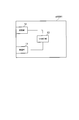
- FIG. 1 is an overall configuration diagram of a mobile communication system according to a first embodiment of the present invention.
- FIG. 2 is a functional block diagram of the radio base station according to the first embodiment of the present invention.
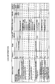
- FIG. 3 is a diagram illustrating an example of a format of “Load Information” used in the mobile communication system according to the first embodiment of the present invention.
- FIG. 4 is a diagram showing an example of a “Load Information” format used in the mobile communication system according to the first embodiment of the present invention.
- FIG. 5 is a diagram for explaining a conventional mobile communication system.
- Mobile communication system Mobile communication system according to the first embodiment of the present invention
- or FIG. 3 the mobile communication system which concerns on the 1st Embodiment of this invention is demonstrated.
- an LTE mobile communication system will be described as an example of the mobile communication system according to the present embodiment, but the present invention is also applicable to mobile communication systems other than the LTE system.
- the mobile communication system according to the present embodiment is configured to be able to perform “ICIC” in order to reduce interference between cells, for example.
- the mobile communication system includes a radio base station eNB # 1 that manages cell # 1 and a radio base station eNB # 2 that manages cell # 2.
- the cells # 1 and # 2 may be macro cells or CSG (Closed Subscriber Group) cells.
- the CSG cell may be referred to as a femto cell, a micro cell, a pico cell, or the like.
- an X2 connection can be set between the radio base station eNB # 1 and the radio base station eNB # 2.
- the mobile station UE is configured to perform CA communication using a plurality of CCs under the control of the radio base stations eNB # 1 / eNB # 2.
- the mobile station UE uses CC # 11a and CC # 11b as downlink CCs and CC # 12a and CCs as uplink CCs under the radio base station eNB # 1.
- CA communication is performed using # 12b.
- the interference level of CC # 11a and CC # 12a is high.
- radio base station eNB # 1 Since the functions of the radio base station eNB # 1 and the radio base station eNB # 2 are basically the same, the function of the radio base station eNB # 1 will be described below as a representative.
- the radio base station eNB # 1 includes a reception unit 11, a transmission unit 12, and a CA control unit 13.
- the receiving unit 11 is configured to receive various signals from the mobile station UE and the surrounding radio base station eNB (for example, the radio base station eNB # 2).
- the receiving unit 11 is configured to receive information related to the CC interference level in the peripheral radio base station eNB from the peripheral radio base station eNB (for example, the radio base station eNB # 2).
- the receiving unit 11 is configured to receive information related to the CC interference level in the neighboring radio base station eNB for each downlink and uplink for each CC (E-CGI: Enhanced-Cell Global Identity). ing.
- the receiving unit 11 is configured to receive information related to the CC interference level in the surrounding radio base station eNB by “Load Information” shown in FIG. 3 or FIG.
- the transmission unit 12 is configured to transmit various signals to the mobile station UE and the surrounding radio base station eNB (for example, the radio base station eNB # 2).
- the transmission unit 12 is configured to transmit information related to the CC interference level in the radio base station eNB # 1 to the neighboring radio base station eNB (for example, the radio base station eNB # 2). ing.
- the transmission unit 12 is configured to transmit information related to the CC interference level in the radio base station eNB # 1 for each CC (E-CGI) for each downlink and uplink.
- the receiving unit 11 is configured to receive information related to the CC interference level in the radio base station eNB # 1 by “Load Information” shown in FIG. 3 or FIG.
- the “Load Information” shown in FIG. 3 is added to the information element “UL Information Overload Indication (system bandwidth) under the information element“ Cell Information Item ”in addition to the information element defined in“ 3GPP TS36.423 ”. Overall)) and the information element “DL Interference Overload Indication (the entire system bandwidth)”.
- the information element “UL Interference Overload Indication (entire system bandwidth)” includes “high interference (high interference level)”, “medium” as the uplink interference level in the CC specified by “Cell ID (E-CGI)”. Either “interference (interference level)” or “low interference (interference level low)” can be set.
- DL Interference Overload Indication (entire system bandwidth)”, “high interference (interference level high)”, “medium” is set as the downlink interference level in the CC specified by “Cell ID (E-CGI)”. Either “interference (interference level)” or “low interference (interference level low)” can be set.
- “Load Information” shown in FIG. 3 is subordinate to the information element “Cell Information Item” and the information element “UL High Information Indication (system whole bandwidth)” ) ”And an information element“ DL High Interference Indication (the entire system bandwidth) ”.
- the information element “UL High Interference Indication (entire system bandwidth)” includes “true (high interference level)” and “false” as the uplink interference level in the CC specified by “Cell ID (E-CGI)”. Any of “interference level low)” can be set.
- the information element “DL High Interference Indication (entire system bandwidth)” includes “true (high interference level)” and “false” as downlink interference levels in the CC specified by “Cell ID (E-CGI)”. Any of “interference level low)” can be set.
- the “Load Information” shown in FIG. 4 is subordinate to the information element “Cell Information Item” and the information element “DL Interface Overload Indication (system wholebandwidth)”. ) ”And an information element“ DL High Interference Indication (the entire system bandwidth) ”.
- DL Interference Overload Indication (entire system bandwidth)”, “high interference (interference level high)”, “medium” is set as the downlink interference level in the CC specified by “Cell ID (E-CGI)”. Either “interference (interference level)” or “low interference (interference level low)” can be set.
- the information element “DL High Interference Indication (entire system bandwidth)” includes “true (high interference level)” and “false” as downlink interference levels in the CC specified by “Cell ID (E-CGI)”. Any of “interference level low)” can be set.
- the CA control unit 11 is configured to control the CA communication of the mobile station UE under the radio base station eNB # 1.
- the CA control unit 11 serves as the serving cell P cell / S cell in the PCC or SCC included in the plurality of CCs based on the interference level notified by the neighboring radio base station eNB (for example, the radio base station eNB # 2). May be configured to determine.
- the CA control unit 11 may be configured not to set a CC having a high interference level as the serving cell P cell / S cell in the surrounding radio base station eNB (for example, the radio base station eNB # 2).
- the CA control unit 11 performs handover from the cell # 1 under the radio base station eNB # 1 of the mobile station UE to the cell under the radio base station eNB (for example, the cell # 2 under the radio base station eNB # 2).
- the CC having a high interference level may not be selected as the serving cell P cell .
- the CA control unit 11 refers to the “Load Information” shown in FIG. 3 and sets the information element “UL Interference Overload Indication (entire system bandwidth)” and the information element “UL High Interference indication (system High)”.
- the uplink interference level in the CC specified by the information element “Cell ID (E-CGI)” may be determined based on at least one of the set values.
- the CA control unit 11 refers to the “Load Information” shown in FIG. 3 and sets the setting value of the information element “DL Interference Overload Indication (entire system bandwidth)” and the information element “DL High Interference indication (system whole)”.
- the downlink interference level in the CC identified by the information element “Cell ID (E-CGI)” may be determined based on at least one of the setting values of “”.
- the CA control unit 11 refers to “Load Information” shown in FIG. 4 and is based on at least one of the setting value of the information element “UL Interference Overload Indication” and the setting value of the information element “UL High Interference Indication”.
- the uplink interference level in the CC specified by the information element “Cell ID (E-CGI)” may be determined.
- the CA control unit 11 has the same CC unit interference when all the “codepoints (high interference, medium interference, low interference)” of the PRB set in the information element “UL Interference Overload Indication” are the same. It may be configured to determine that such a value is set as the level (that is, the interference level of the entire system bandwidth).
- the CA control unit 11 It may be configured to determine that such a value is set as the unit interference level (that is, the interference level of the entire system bandwidth).
- the CA control unit 11 refers to “Load Information” shown in FIG. 4 and is based on at least one of the setting value of the information element “DL Interference Overload Indication” and the setting value of the information element “DL High Interference Indication”.
- the downlink interference level in the CC specified by the information element “Cell ID (E-CGI)” may be determined.
- the mobile communication system it is possible to exchange the interference level in units of CC for each downlink and uplink between adjacent radio base stations eNB using “Load Information”.
- a first feature of the present embodiment is a mobile communication method in which the mobile station UE performs CA communication using a plurality of CCs (carriers) under the control of the radio base stations eNB # 1 / eNB # 2, and the radio base station eNB # 1 / eNB # 2 has a step of notifying a neighboring radio base station eNB # 2 / eNB # 1 of an interference level for each CC included in a plurality of CCs for each downlink and uplink. Is the gist.
- wireless base station eNB # 1 / eNB # 2 serves as a serving cell in PCC (main carrier) or SCC (subcarrier) contained in several CC You may further have the process of determining Pcell / Scell .
- a second feature of the present embodiment is a mobile communication system configured such that the mobile station UE can perform CA communication using a plurality of CCs under the control of the radio base stations eNB # 1 / eNB # 2.
- the gist of the present invention is to provide a transmitter 12 configured to notify
- the CA control unit 13 configured to determine the serving cell P cell / S cell in the PCC or SCC included in the plurality of CCs based on the notified interference level is further provided. You may have.
- radio base stations eNB # 1 / eNB # 2 and the mobile station UE described above may be implemented by hardware, may be implemented by a software module executed by a processor, or a combination of both May be implemented.
- the software modules include RAM (Random Access Memory), flash memory, ROM (Read Only Memory), EPROM (Erasable Programmable ROM), EEPROM (Electronically Erasable and Programmable, Removable ROM, Hard Disk, and Removable ROM).
- RAM Random Access Memory
- flash memory ROM (Read Only Memory)
- EPROM Erasable Programmable ROM
- EEPROM Electrically Erasable and Programmable, Removable ROM, Hard Disk, and Removable ROM.
- it may be provided in a storage medium of an arbitrary format such as a CD-ROM.
- the storage medium is connected to the processor so that the processor can read and write information from and to the storage medium. Further, such a storage medium may be integrated in the processor. Such a storage medium and processor may be provided in the ASIC. Such an ASIC may be provided in the radio base station eNB or the mobile station UE. Further, the storage medium and the processor may be provided in the radio base station eNB # 1 / eNB # 2 or the mobile station UE as a discrete component.
- eNB # 1, eNB # 2 radio base station 11 ... transmitting unit 12 ... receiving unit 13 ... CA control unit UE ... mobile station
Abstract
隣接する無線基地局eNB間で、CC単位の干渉レベルを交換する。本発明に係る移動通信方法は、無線基地局eNB#1/eNB#2が、周辺無線基地局eNB#2/eNB#1に対して、複数のCCに含まれるCCごとに、下りリンク及び上りリンク別に、干渉レベルについて通知する工程を有する。
Description
本発明は、移動通信方法及び無線基地局に関する。
図5に示すように、LTE(Long Term Evolution)方式において、無線基地局eNBが、隣接する無線基地局eNBとの間で、周波数領域(Frequency Domain)で、上りリンクにおけるPRB(Physical Resource Block:物理リソースブロック)単位で、「High interference PRB」として、干渉レベルの高いPRBに係る情報を交換し、干渉レベルの高いPRBへのスケジューリングを回避する方法が規定されている。
また、LTE-Advanced方式では、移動局UEは、1つの無線基地局eNB配下の複数のキャリア(CC:Component Carrier)を用いて、CA(Carrier Aggregation)通信を行うことができるように構成されている。
ここで、CA通信における周波数領域で干渉を低減する「ICIC( Inter Cell Interference Coordination)」として、例えば、干渉レベルの高いCCを、PCC(Primary Component Carrier:主キャリア)又はSCC(Secondary Component Carrier:副キャリア)におけるサービングセルPcell/Scellに設定しないという方法が考えられる。
3GPP TS36.300
3GPP TS36.423
3GPP TS36.213
しかしながら、従来のLTE方式では、無線基地局eNBが、上りリンクにおけるPRB単位で、「High interference PRB」を通知するように構成されているため、隣接する無線基地局eNB間で、CC単位の干渉レベル(すなわち、システム帯域幅全体の干渉レベル)について交換することができない。
特に、従来のLTE方式では、隣接する無線基地局eNB間で、下りリンクにおける干渉レベルについて交換することができない。
したがって、従来のLTE方式における隣接する無線基地局間の干渉レベルの交換方法では、上述のCA通信における周波数領域でのCC単位の「ICIC」を実現することができないという問題点があった。
そこで、本発明は、上述の課題に鑑みてなされたものであり、隣接する無線基地局eNB間で、CC単位の干渉レベルを交換することができる移動通信方法及び無線基地局を提供することを目的とする。
本発明の第1の特徴は、移動局が、無線基地局配下の複数のキャリアを用いて通信を行う移動通信方法であって、前記無線基地局が、周辺無線基地局に対して、前記複数のキャリアに含まれるキャリアごとに、下りリンク及び上りリンク別に、干渉レベルについて通知する工程を有することを要旨とする。
本発明の第2の特徴は、移動局が、無線基地局配下の複数のキャリアを用いて通信を行うことができるように構成されている移動通信システムで用いられる無線基地局であって、周辺無線基地局に対して、前記複数のキャリアに含まれるキャリアごとに、下りリンク及び上りリンク別に、干渉レベルについて通知するように構成されている送信部を具備することを要旨とする。
(本発明の第1の実施形態に係る移動通信システム)
図1乃至図3を参照して、本発明の第1の実施形態に係る移動通信システムについて説明する。本実施形態では、本実施形態に係る移動通信システムとして、LTE方式の移動通信システムを例示して説明するが、本発明は、LTE方式以外の移動通信システムにも適用可能である。
図1乃至図3を参照して、本発明の第1の実施形態に係る移動通信システムについて説明する。本実施形態では、本実施形態に係る移動通信システムとして、LTE方式の移動通信システムを例示して説明するが、本発明は、LTE方式以外の移動通信システムにも適用可能である。
なお、本実施形態に係る移動通信システムでは、例えば、セル間の干渉を低減するために、「ICIC」を行うことができるように構成されている。
図1に示すように、本実施形態に係る移動通信システムは、セル#1を管理する無線基地局eNB#1と、セル#2を管理する無線基地局eNB#2とを具備している。
なお、セル#1及び#2は、マクロセルであってもよいし、CSG(Closed Subscriber Group)セルであってもよい。なお、CSGセルは、フェムト(Femto)セルやマイクロ(Micro)セルやピコ(Pico)セル等と呼ばれてもよい。
また、無線基地局eNB#1と無線基地局eNB#2との間では、X2コネクションを設定することができるように構成されている。
移動局UEは、無線基地局eNB#1/eNB#2配下の複数のCCを用いてCA通信を行うことができるように構成されている。
図1の例では、移動局UEは、無線基地局eNB#1配下において、下りリンク用CCとして、CC#11a及びCC#11bを用いて、かつ、上りリンク用CCとして、CC#12a及びCC#12bを用いて、CA通信を行っている。
その結果、無線基地局eNB#2において、CC#11a及びCC#12aの干渉レベルが高くなっている。
無線基地局eNB#1及び無線基地局eNB#2の機能は、基本的に同一であるため、以下、代表して、無線基地局eNB#1の機能について説明する。
図2に示すように、無線基地局eNB#1は、受信部11と、送信部12と、CA制御部13とを具備している。
受信部11は、移動局UE及び周辺無線基地局eNB(例えば、無線基地局eNB#2)から、各種信号を受信するように構成されている。
具体的には、受信部11は、周辺無線基地局eNB(例えば、無線基地局eNB#2)から、周辺無線基地局eNBにおけるCCの干渉レベルに係る情報を受信するように構成されている。
ここで、受信部11は、CC(E-CGI:Enhanced-Cell Global Identity)ごとに、下りリンク及び上りリンク別に、周辺無線基地局eNBにおけるCCの干渉レベルに係る情報を受信するように構成されている。
例えば、受信部11は、図3又は図4に示す「Load Information」によって、周辺無線基地局eNBにおけるCCの干渉レベルに係る情報を受信するように構成されている。
送信部12は、移動局UE及び周辺無線基地局eNB(例えば、無線基地局eNB#2)に対して、各種信号を送信するように構成されている。
具体的には、送信部12は、周辺無線基地局eNB(例えば、無線基地局eNB#2)に対して、無線基地局eNB#1におけるCCの干渉レベルに係る情報を送信するように構成されている。
ここで、送信部12は、CC(E-CGI)ごとに、下りリンク及び上りリンク別に、無線基地局eNB#1におけるCCの干渉レベルに係る情報を送信するように構成されている。
例えば、受信部11は、図3又は図4に示す「Load Information」によって、無線基地局eNB#1におけるCCの干渉レベルに係る情報を受信するように構成されている。
ここで、図3に示す「Load Information」は、「3GPP TS36.423」に規定されている情報要素に加えて、情報要素「Cell Information Item」配下に、情報要素「UL Interference Overload Indication(system bandwidth全体)」及び情報要素「DL Interference Overload Indication(system bandwidth全体)」を有している。
情報要素「UL Interference Overload Indication(system bandwidth全体)」には、「Cell ID(E-CGI)」によって特定されるCCにおける上りリンクの干渉レベルとして、「high interference(干渉レベル高)」、「medium interference(干渉レベル中)」及び「low interference(干渉レベル低)」のいずれかが設定可能である。
情報要素「DL Interference Overload Indication(system bandwidth全体)」には、「Cell ID(E-CGI)」によって特定されるCCにおける下りリンクの干渉レベルとして、「high interference(干渉レベル高)」、「medium interference(干渉レベル中)」及び「low interference(干渉レベル低)」のいずれかが設定可能である。
また、図3に示す「Load Information」は、「3GPP TS36.423」に規定されている情報要素に加えて、情報要素「Cell Information Item」配下に、情報要素「UL High Interference Indication(system bandwidth全体)」及び情報要素「DL HIgh Interference Indication(system bandwidth全体)」を有している。
情報要素「UL High Interference Indication(system bandwidth全体)」には、「Cell ID(E-CGI)」によって特定されるCCにおける上りリンクの干渉レベルとして、「true(干渉レベル高)」及び「false(干渉レベル低)」のいずれかが設定可能である。
情報要素「DL High Interference Indication(system bandwidth全体)」には、「Cell ID(E-CGI)」によって特定されるCCにおける下りリンクの干渉レベルとして、「true(干渉レベル高)」及び「false(干渉レベル低)」のいずれかが設定可能である。
また、図4に示す「Load Information」は、「3GPP TS36.423」に規定されている情報要素に加えて、情報要素「Cell Information Item」配下に、情報要素「DL Interference Overload Indication(system bandwidth全体)」及び情報要素「DL High Interference Indication(system bandwidth全体)」を有している。
情報要素「DL Interference Overload Indication(system bandwidth全体)」には、「Cell ID(E-CGI)」によって特定されるCCにおける下りリンクの干渉レベルとして、「high interference(干渉レベル高)」、「medium interference(干渉レベル中)」及び「low interference(干渉レベル低)」のいずれかが設定可能である。
情報要素「DL High Interference Indication(system bandwidth全体)」には、「Cell ID(E-CGI)」によって特定されるCCにおける下りリンクの干渉レベルとして、「true(干渉レベル高)」及び「false(干渉レベル低)」のいずれかが設定可能である。
CA制御部11は、無線基地局eNB#1配下における移動局UEのCA通信を制御するように構成されている。
ここで、CA制御部11は、周辺無線基地局eNB(例えば、無線基地局eNB#2)によって通知された干渉レベルに基づいて、複数のCCに含まれるPCC又はSCCにおけるサービングセルPcell/Scellを決定するように構成されていてもよい。
例えば、CA制御部11は、周辺無線基地局eNB(例えば、無線基地局eNB#2)において干渉レベルの高いCCを、サービングセルPcell/Scellとしないように構成されていてもよい。
また、CA制御部11は、移動局UEの無線基地局eNB#1配下のセル#1から周辺無線基地局eNB配下のセル(例えば、無線基地局eNB#2配下のセル#2)へのハンドオーバにおいて、干渉レベルの高いCCを、サービングセルPcellとして選択しないように構成されていてもよい。
なお、CA制御部11は、図3に示す「Load Information」を参照して、情報要素「UL Interference Overload Indication(system bandwidth全体)」の設定値及び情報要素「UL High Interference Indication(system bandwidth全体)」の設定値の少なくとも1つに基づいて、情報要素「Cell ID(E-CGI)」によって特定されるCCにおける上りリンクの干渉レベルを決定するように構成されていてもよい。
また、CA制御部11は、図3に示す「Load Information」を参照して、情報要素「DL Interference Overload Indication(system bandwidth全体)」の設定値及び情報要素「DL High Interference Indication(system bandwidth全体)」の設定値の少なくとも1つに基づいて、情報要素「Cell ID(E-CGI)」によって特定されるCCにおける下りリンクの干渉レベルを決定するように構成されていてもよい。
また、CA制御部11は、図4に示す「Load Information」を参照して、情報要素「UL Interference Overload Indication」の設定値及び情報要素「UL High Interference Indication」の設定値の少なくとも1つに基づいて、情報要素「Cell ID(E-CGI)」によって特定されるCCにおける上りリンクの干渉レベルを決定するように構成されていてもよい。
ここで、CA制御部11は、情報要素「UL Interference Overload Indication」に設定されているPRBの全ての「codepoint(high interferene、medium interference、low interference)」が同じであった場合、CC単位の干渉レベル(すなわち、システム帯域幅全体の干渉レベル)として、かかる値が設定されていると判断するように構成されていてもよい。
同様に、CA制御部11は、情報要素「UL High Interference Indication」に設定されているPRBの全ての「codepoint(1:干渉が高い、0:干渉が低い)」が同じであった場合、CC単位の干渉レベル(すなわち、システム帯域幅全体の干渉レベル)として、かかる値が設定されていると判断するように構成されていてもよい。
また、CA制御部11は、図4に示す「Load Information」を参照して、情報要素「DL Interference Overload Indication」の設定値及び情報要素「DL High Interference Indication」の設定値の少なくとも1つに基づいて、情報要素「Cell ID(E-CGI)」によって特定されるCCにおける下りリンクの干渉レベルを決定するように構成されていてもよい。
本実施形態に係る移動通信システムによれば、「Load Information」を用いて、隣接する無線基地局eNB間で、下りリンク及び上りリンク別に、CC単位の干渉レベルを交換することができる。
以上に述べた本実施形態の特徴は、以下のように表現されていてもよい。
本実施形態の第1の特徴は、移動局UEが、無線基地局eNB#1/eNB#2配下の複数のCC(キャリア)を用いてCA通信を行う移動通信方法であって、無線基地局eNB#1/eNB#2が、周辺無線基地局eNB#2/eNB#1に対して、複数のCCに含まれるCCごとに、下りリンク及び上りリンク別に、干渉レベルについて通知する工程を有することを要旨とする。
本実施形態の第1の特徴において、無線基地局eNB#1/eNB#2が、通知された干渉レベルに基づいて、複数のCCに含まれるPCC(主キャリア)又はSCC(副キャリア)におけるサービングセルPcell/Scellを決定する工程を更に有してもよい。
本実施形態の第2の特徴は、移動局UEが、無線基地局eNB#1/eNB#2配下の複数のCCを用いてCA通信を行うことができるように構成されている移動通信システムで用いられる無線基地局eNB#1/eNB#2であって、周辺無線基地局eNB#2/eNB#1に対して、複数のCCに含まれるCCごとに、下りリンク及び上りリンク別に、干渉レベルについて通知するように構成されている送信部12を具備することを要旨とする。
本実施形態の第2の特徴において、通知された干渉レベルに基づいて、複数のCCに含まれるPCC又はSCCにおけるサービングセルPcell/Scellを決定するように構成されているCA制御部13を更に具備してもよい。
なお、上述の無線基地局eNB#1/eNB#2や移動局UEの動作は、ハードウェアによって実施されてもよいし、プロセッサによって実行されるソフトウェアモジュールによって実施されてもよいし、両者の組み合わせによって実施されてもよい。
ソフトウェアモジュールは、RAM(Random Access Memory)や、フラッシュメモリや、ROM(Read Only Memory)や、EPROM(Erasable Programmable ROM)や、EEPROM(Electronically Erasable and Programmable ROM)や、レジスタや、ハードディスクや、リムーバブルディスクや、CD-ROMといった任意形式の記憶媒体内に設けられていてもよい。
かかる記憶媒体は、プロセッサが当該記憶媒体に情報を読み書きできるように、当該プロセッサに接続されている。また、かかる記憶媒体は、プロセッサに集積されていてもよい。また、かかる記憶媒体及びプロセッサは、ASIC内に設けられていてもよい。かかるASICは、無線基地局eNBや移動局UE内に設けられていてもよい。また、かかる記憶媒体及びプロセッサは、ディスクリートコンポーネントとして無線基地局eNB#1/eNB#2や移動局UE内に設けられていてもよい。
以上、上述の実施形態を用いて本発明について詳細に説明したが、当業者にとっては、本発明が本明細書中に説明した実施形態に限定されるものではないということは明らかである。本発明は、請求の範囲の記載により定まる本発明の趣旨及び範囲を逸脱することなく修正及び変更態様として実施することができる。従って、本明細書の記載は、例示説明を目的とするものであり、本発明に対して何ら制限的な意味を有するものではない。
なお、日本国特許出願第2011‐122196号(2011年5月31日出願)の全内容が、参照により、本願明細書に組み込まれている。
以上説明したように、本発明によれば、隣接する無線基地局eNB間で、CC単位の干渉レベルを交換することができる移動通信方法及び無線基地局を提供することができる。
eNB#1、eNB#2…無線基地局
11…送信部
12…受信部
13…CA制御部
UE…移動局
11…送信部
12…受信部
13…CA制御部
UE…移動局
Claims (4)
- 移動局が、無線基地局配下の複数のキャリアを用いて通信を行う移動通信方法であって、
前記無線基地局が、周辺無線基地局に対して、前記複数のキャリアに含まれるキャリアごとに、下りリンク及び上りリンク別に、干渉レベルについて通知する工程を有することを特徴とする移動通信方法。 - 前記無線基地局が、通知された前記干渉レベルに基づいて、前記複数のキャリアに含まれる主キャリア又は副キャリアにおけるサービングセルを決定する工程を更に有することを特徴とする請求項1に記載の移動通信方法。
- 移動局が、無線基地局配下の複数のキャリアを用いて通信を行うことができるように構成されている移動通信システムで用いられる無線基地局であって、
周辺無線基地局に対して、前記複数のキャリアに含まれるキャリアごとに、下りリンク及び上りリンク別に、干渉レベルについて通知するように構成されている送信部を具備することを特徴とする無線基地局。 - 通知された前記干渉レベルに基づいて、前記複数のキャリアに含まれる主キャリア又は副キャリアにおけるサービングセルを決定するように構成されている制御部を更に具備することを特徴とする請求項3に記載の無線基地局。
Applications Claiming Priority (2)
| Application Number | Priority Date | Filing Date | Title |
|---|---|---|---|
| JP2011-122196 | 2011-05-31 | ||
| JP2011122196A JP2012253407A (ja) | 2011-05-31 | 2011-05-31 | 移動通信方法及び無線基地局 |
Publications (1)
| Publication Number | Publication Date |
|---|---|
| WO2012165475A1 true WO2012165475A1 (ja) | 2012-12-06 |
Family
ID=47259327
Family Applications (1)
| Application Number | Title | Priority Date | Filing Date |
|---|---|---|---|
| PCT/JP2012/063922 WO2012165475A1 (ja) | 2011-05-31 | 2012-05-30 | 移動通信方法及び無線基地局 |
Country Status (2)
| Country | Link |
|---|---|
| JP (1) | JP2012253407A (ja) |
| WO (1) | WO2012165475A1 (ja) |
Families Citing this family (1)
| Publication number | Priority date | Publication date | Assignee | Title |
|---|---|---|---|---|
| GB2499222A (en) | 2012-02-08 | 2013-08-14 | Nec Corp | Generating a measurement report comprising information calculated from a power ratio of a non-zero power almost blank sub-frame |
Citations (1)
| Publication number | Priority date | Publication date | Assignee | Title |
|---|---|---|---|---|
| WO2011052643A1 (ja) * | 2009-10-29 | 2011-05-05 | 日本電気株式会社 | 無線通信システム、無線通信方法、無線局、およびプログラム |
-
2011
- 2011-05-31 JP JP2011122196A patent/JP2012253407A/ja not_active Withdrawn
-
2012
- 2012-05-30 WO PCT/JP2012/063922 patent/WO2012165475A1/ja active Application Filing
Patent Citations (1)
| Publication number | Priority date | Publication date | Assignee | Title |
|---|---|---|---|---|
| WO2011052643A1 (ja) * | 2009-10-29 | 2011-05-05 | 日本電気株式会社 | 無線通信システム、無線通信方法、無線局、およびプログラム |
Non-Patent Citations (1)
| Title |
|---|
| NOKIA SIEMENS NETWORKS ET AL.: "Primary Component Carrier Selection, Monitoring, and Recovery", 3GPP TSG RAN WG1 #57 MEETING R1-091779, 4 May 2009 (2009-05-04), Retrieved from the Internet <URL:http://www.3gpp.org/ftp/tsg_ran/wg1_r11/TSGR1_57/Docs/R1-091779.zip> [retrieved on 20120613] * |
Also Published As
| Publication number | Publication date |
|---|---|
| JP2012253407A (ja) | 2012-12-20 |
Similar Documents
| Publication | Publication Date | Title |
|---|---|---|
| CN109565852B (zh) | 具有无线回程的无线网络中的动态资源分配 | |
| JP5438046B2 (ja) | 移動通信方法及び無線基地局 | |
| US20130142175A1 (en) | Efficient spectrum utilization with almost blank subframes | |
| US11290986B2 (en) | Dynamic resource allocation in wireless network | |
| RU2568679C1 (ru) | Базовая радиостанция и мобильная станция | |
| JP5388244B1 (ja) | 移動局 | |
| JP5905749B2 (ja) | 無線基地局 | |
| WO2012063932A1 (ja) | 移動通信方法及び無線基地局 | |
| US9788191B2 (en) | Mobile station and radio base station | |
| EP2811800B1 (en) | Mobile communication method, wireless base station, and mobile station | |
| US9549422B2 (en) | Radio base station | |
| EP2996392B1 (en) | Mobile communication system for handover with signaling diversity | |
| JP5536714B2 (ja) | 移動通信方法及び無線基地局 | |
| WO2012165475A1 (ja) | 移動通信方法及び無線基地局 | |
| JP2013183270A (ja) | 移動通信システム | |
| US9655146B2 (en) | Mobile communication method and mobile station | |
| US9577777B2 (en) | Method and apparatus for controlling inter-cellular interference in HetNet system | |
| JP6032904B2 (ja) | 移動局および無線基地局 | |
| JP5281704B1 (ja) | 無線基地局 | |
| JP5827914B2 (ja) | 移動局 | |
| WO2013187317A1 (ja) | 無線基地局 | |
| JP2012080445A (ja) | 移動通信システム及び無線基地局 |
Legal Events
| Date | Code | Title | Description |
|---|---|---|---|
| 121 | Ep: the epo has been informed by wipo that ep was designated in this application |
Ref document number: 12792377 Country of ref document: EP Kind code of ref document: A1 |
|
| NENP | Non-entry into the national phase |
Ref country code: DE |
|
| 122 | Ep: pct application non-entry in european phase |
Ref document number: 12792377 Country of ref document: EP Kind code of ref document: A1 |